

Page 1
Para obtener un ejemplar en Español de este
Manual del propietario, visite www.heatnglo.com.
Model:
Twilight-II-B
TwilightLP-II-B
Pour demander un exemplaire en français de ce Manuel
du propriétaire, visitez www.heatnglo.com.
Owner’s Manual
Installation and Operation
NOTICE
DO NOT DISCARD THIS MANUAL
• Important operating
and maintenance
instructions included.
WARNING: If the information in these
instructions is not followed exactly, a fi re
or explosion may result causing property
damage, personal injury, or death.
• DO NOT store or use gasoline or other fl am-
mable vapors and liquids in the vicinity of this
or any other appliance.
• What to do if you smell gas
- DO NOT try to light any appliance.
- DO NOT touch any electrical switch. DO
NOT use any phone in your building.
- Immediately call your gas supplier from a
neighbor’s phone. Follow the gas supplier’s instructions.
- If you cannot reach your gas supplier, call
the fi re department.
• Installation and service must be performed
by a qualifi ed installer, service agency , or the
gas supplier.
This appliance may be installed as an OEM installation in
manufactured home (USA only) or mobile home and must be
installed in accordance with the manufacturer’s instructions
and the manufactured home construction and safety standard,
Title 24 CFR, Part 3280 or Standard for Installation in Mobile
Homes, CAN/CSA Z240MH, in Canada.
This appliance is only for use with the type(s) of gas indicated
on the rating plate.
• Read, understand and follow
these instructions for safe
installation and operation.
DO NOT
DISCARD
• Leave this manual with
party responsible for use
and operation.
WARNING
HOT SURFACES!
Glass and other surfaces are hot during
operation AND cool down.
Hot glass will cause burns.
• DO NOT touch glass until it is cooled
• NEVER allow children to touch glass
• Keep children away
• CAREFULLY SUPERVISE children in same room as
fi replace.
• Alert children and adults to hazards of high temperatures.
High temperatures may ignite clothing or other fl ammable
materials.
• Keep clothing, furniture, draperies and other fl ammable
materials away.
This appliance has been supplied with an integral barrier
to prevent direct contact with the fi xed glass panel. DO
NOT operate the appliance with the barrier removed.
Contact your dealer or Hearth & Home Technologies if the
barrier is not present or help is needed to properly install one.
In the Commonwealth of Massachusetts installation must be
performed by a licensed plumber or gas fi tter.
See Table of Contents for location of additional Commonwealth
of Massachusetts requirements.
Installation and service of this appliance should be
performed by qualifi ed personnel. Hearth & Home
Technologies suggests NFI certifi ed or factory trained
professionals, or technicians supervised by an NFI
certifi ed professional.
1Outdoor Lifestyles by Hearth & Home Technologies, Inc. • Twilight-II-B • 2108-900 Rev. Z • 9/12
Page 2
doit
Not Not for for use use with with solid solid fuel.fuel.
((Ne Ne doit pas pas entre entre utilise utilise avec avec un un combustible combustible solide).solide).
This This appliance appliance must must be be installed installed in in accordance accordance with with local local codes, codes, if if any; any; if if not, not, follow follow ANSI ANSI Z223.1Z223.1
in in the the USA USA or or CAN/CGA CAN/CG A B149 B149 installation installation codes. codes. (Installer (Installer l’appareil l’appareil selon selon les les codes codes ou ou reglementsreglements
locaux locaux ou, ou, en en l’absence l’absence de de tels tels reglements, reglements, selon selon les les codes codes d’installation d’installation CAN/CGA-B149.)CAN/CGA-B149.)
Type Type of of Gas Gas (Sorte (Sorte De De Gaz)Gaz)::
NNAATURALTURAL GASGAS
MADE MADE IN IN USAUSA
Minimum Minimum Permissible Permissible Gas Gas Supply Supply for for Purposes Purposes of of Input Input Adjustment.Adjustment.
Approved Approved Minimum Minimum (De (De Gaz) Gaz) AcceptableAcceptable 0.00.0 in in w.c.w.c. (Po. (Po. Col. Col. d’eau)d’eau)
Maximum Maximum Pressure Pressure (Pression)(Pression) 0.00.0 in in w.c.w.c. (Po. (Po. Col. Col. d’eau)d’eau)
Maximum Maximum Manifold Manifold Pressure Pressure (Pression)(Pression) 0.00.0 in in w.c.w.c. (Po. (Po. Col. Col. d’eau)d’eau)
Minimum Minimum Manifold Manifold Pressure Pressure (Pression)(Pression) 0.00.0 in in w.c.w.c. (Po. (Po. Col. Col. d’eau)d’eau)
Model:Model:
(Modele):(Modele):
SerialSerial
(Serie):(Serie):
ANSI ANSI Z21XX-XXXX Z21XX-XXXX · · CSA CSA 2.XX-MXX 2.XX-MXX · · UL307BUL307B
XXXXXXXXXXXXXXXX
IN IN CANADACANADA
ALTITUDE:ALTITUDE: 0-0000 0-0000 FT.FT. 0000-0000FT.0000-0000FT.
MAX. MAX. INPUT INPUT BTUH:BTUH: 00,00000,000 00,00000,000
MIN. MIN. INPUT INPUT BTUH:BTUH: 00,00000,000 00,00000,000
ORIFICE ORIFICE SIZE:SIZE: #XXXXX#XXXXX #XXXXX#XXXXX
XXXXXXXXXXXXXXXX
Total Total Electrical Electrical Requirements: Requirements: 000Vac, 000Vac, 00Hz., 00Hz., less less than than 00 00 AmperesAmperes
Heat & Glo, a brand of Hearth & Home Technologies, Inc.
7571 215th Street West, Lakeville, MN 55044
Read this manual before installing or operating this appliance.
Please retain this owner’s manual for future reference.
A. Congratulations
Congratulations on selecting an Outdoor LifeStyles gas
fi replace, an elegant and clean alternative to wood burning
fi replaces. The Outdoor LifeStyles gas fi replace you have
selected is designed to provide the utmost in safety,
reliability, and effi ciency .
As the owner of a new fi replace, you’ll want to read and
carefully follow all of the instructions contained in this
owner’s manual. Pay special attention to all cautions and
warnings.
Homeowner Reference Information
This owner’s manual should be retained for future
reference. We suggest that you keep it with your other
important documents and product manuals.
The information contained in this owner’s manual, unless
noted otherwise, applies to all models and gas control
systems.
Your new Outdoor LifeStyles gas fi replace will give you
years of durable use and trouble-free enjoyment. Welcome
to the Hearth & Home Technologies family of fi replace
products!
We recommend that you record the following pertinent
information about your fi replace.
Model Name: ___________________________________________ Date purchased/installed: __________________
Serial Number: __________________________________________ Location on fi replace: _____________________
Dealership purchased from: _______________________________ Dealer Phone: __________________________
Notes: _______________________________________________________________________________________
_____________________________________________________________________________________________
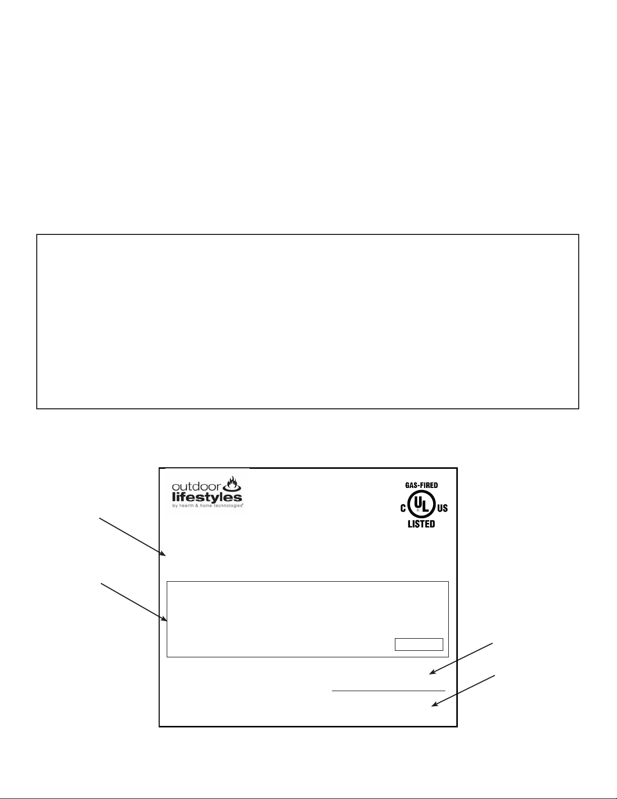
Listing Label Information/Location
Type of Gas
Gas and Electric
Information
The model information regarding your specifi c fi replace can be found on
the rating plate usually located in the control area of the fi replace.
Model Number
Serial Number
2
Outdoor Lifestyles by Hearth & Home Technologies, Inc. • Twilight-II-B • 2108-900 Rev. Z • 9/12
Page 3

Safety Alert Key:
• DANGER! Indicates a hazardous situation which, if not avoided will result in death or serious injury.
• WARNING! Indicates a hazardous situation which, if not avoided could result in death or serious injury.
• CAUTION! Indicates a hazardous situation which, if not avoided, could result in minor or moderate injury.
• NOTICE: Used to address practices not related to personal injury.
Table of Contents
A. Congratulations . . . . . . . . . . . . . . . . . . . . . . . . . . . . . . . . . 2
B. Limited Lifetime Warranty . . . . . . . . . . . . . . . . . . . . . . . . . . 4
1 Listing and Code Approvals
A. Appliance Certifi cation . . . . . . . . . . . . . . . . . . . . . . . . . . . . 6
B. Tempered Glass Specifi cations . . . . . . . . . . . . . . . . . . . . . 6
C. Thermal Performance Data . . . . . . . . . . . . . . . . . . . . . . . . 6
D. Air Infi ltration, Water Resistance and Structural Tests . . . 6
E. BTU Specifi cations . . . . . . . . . . . . . . . . . . . . . . . . . . . . . . . 6
F. High Altitude Installations . . . . . . . . . . . . . . . . . . . . . . . . . . 7
G. Non-Combustible Materials Specifi cation. . . . . . . . . . . . . . 7
H. Combustible Materials Specifi cation . . . . . . . . . . . . . . . . . 7
I. Electrical Codes . . . . . . . . . . . . . . . . . . . . . . . . . . . . . . . . . 7
J. Requirements for the Commonwealth of Massachusetts . . 8
User Guide
2 Operating Instructions
A. Gas Fireplace Safety . . . . . . . . . . . . . . . . . . . . . . . . . . . . . 9
B. Your Fireplace . . . . . . . . . . . . . . . . . . . . . . . . . . . . . . . . . . 9
C. Fan Kit (optional) . . . . . . . . . . . . . . . . . . . . . . . . . . . . . . . 10
D. Clear Space . . . . . . . . . . . . . . . . . . . . . . . . . . . . . . . . . . . 10
E. Decorative Doors and Fronts . . . . . . . . . . . . . . . . . . . . . . 10
F. Fixed Glass Assembly . . . . . . . . . . . . . . . . . . . . . . . . . . . 10
G. Remote Controls, Wall Controls and Wall Switches . . . . . 10
H. Before Lighting Fireplace . . . . . . . . . . . . . . . . . . . . . . . . . 10
I. Lighting Instructions (IPI) . . . . . . . . . . . . . . . . . . . . . . . . . 11
J. After Fireplace is Lit . . . . . . . . . . . . . . . . . . . . . . . . . . . . . 12
K. Frequently Asked Questions . . . . . . . . . . . . . . . . . . . . . . 12
3 Maintenance and Service
A. Maintenance Tasks-Homeowner . . . . . . . . . . . . . . . . . . . 13
B. Maintenance Tasks-Qualifi ed Service Technician . . . . . . 14
Installer Guide
4 Getting Started
A. Design and Installation Considerations . . . . . . . . . . . . . . 16
B. Tools and Supplies Needed . . . . . . . . . . . . . . . . . . . . . . . 16
C. Inspect Appliance and Components . . . . . . . . . . . . . . . . . 16
5 Framing and Clearances
A. Selecting Appliance Location . . . . . . . . . . . . . . . . . . . . . . 17
B. Clearances . . . . . . . . . . . . . . . . . . . . . . . . . . . . . . . . . . . . 18
C. Mantel and Wall Projections . . . . . . . . . . . . . . . . . . . . . . . 19
6 Termination Locations
A. Appliance Opening Minimum Clearances . . . . . . . . . . . . 20
7 Appliance Preparation
A. Removing Non-combustible Facing Material Assembly . . 21
B. Securing and Leveling the Appliance . . . . . . . . . . . . . . . . 21
C. Installing Non-combustible Facing Material
(Outdoor Side) . . . . . . . . . . . . . . . . . . . . . . . . . . . . . . . . . 24
8 Gas Information
A. Fuel Conversion . . . . . . . . . . . . . . . . . . . . . . . . . . . . . . . . 25
B. Gas Pressure . . . . . . . . . . . . . . . . . . . . . . . . . . . . . . . . . . 25
C. Gas Connection . . . . . . . . . . . . . . . . . . . . . . . . . . . . . . . . 25
D. High Altitude Installations . . . . . . . . . . . . . . . . . . . . . . . . . 25
9 Electrical Information
A. Wiring Requirements . . . . . . . . . . . . . . . . . . . . . . . . . . . . 26
B. Connecting to the Appliance. . . . . . . . . . . . . . . . . . . . . . . 26
C. Intellifi re Ignition System Wiring . . . . . . . . . . . . . . . . . . . . 27
D. Optional Accessories . . . . . . . . . . . . . . . . . . . . . . . . . . . . 28
E. Junction Box Installation. . . . . . . . . . . . . . . . . . . . . . . . . . 29
F. Wall Switch Installation for Fan (Optional) . . . . . . . . . . . . 29
10 Finishing
A. Mantel and Wall Projections . . . . . . . . . . . . . . . . . . . . . . . 30
B. Facing Material . . . . . . . . . . . . . . . . . . . . . . . . . . . . . . . . . 30
11 Appliance Setup
A. Remove Fixed Glass Assembly . . . . . . . . . . . . . . . . . . . . 33
B. Remove the Shipping Materials . . . . . . . . . . . . . . . . . . . . 33
C. Clean the Appliance . . . . . . . . . . . . . . . . . . . . . . . . . . . . . 33
D. Accessories . . . . . . . . . . . . . . . . . . . . . . . . . . . . . . . . . . . 33
E. Lava Rock and Ember Placement . . . . . . . . . . . . . . . . . . 33
F. Install the Log Assembly. . . . . . . . . . . . . . . . . . . . . . . . . . 34
G. Fixed Glass Assembly . . . . . . . . . . . . . . . . . . . . . . . . . . . 37
H. Install Trim and/or Surround . . . . . . . . . . . . . . . . . . . . . . . 37
I. Air Shutter Setting . . . . . . . . . . . . . . . . . . . . . . . . . . . . . . 37
12 Troubleshooting
A. Intellifi re Ignition System . . . . . . . . . . . . . . . . . . . . . . . . . 38
13 Reference Materials
A. Appliance Dimension Diagram . . . . . . . . . . . . . . . . . . . . . 40
B. Service Parts . . . . . . . . . . . . . . . . . . . . . . . . . . . . . . . . . . 41
C. Contact Information . . . . . . . . . . . . . . . . . . . . . . . . . . . . . 44
= Contains updated information.
3Outdoor Lifestyles by Hearth & Home Technologies, Inc. • Twilight-II-B • 2108-900 Rev. Z • 9/12
Page 4

B. Limited Lifetime Warranty
Outdoor Lifestyles by Hearth & Home Technologies, Inc.™
Limited Warranty
Hearth & Home Technologies, Inc. (“HHT”) extends the following warranty for all Outdoor Lifestyles by
HHT™ brand products (“Products”) that are purchased from an HHT authorized dealer.
WARRANTY COVERAGE:
HHT warrants to the original owner of the Product at the site of installation, and to any transferee taking
ownership of the Product at the site of installation within one year following the date of original purchase,
that the Product will be free from defects in materials and workmanship at the time of manufacture. After
installation, if covered components manufactured by HHT are found to be defective in materials or
workmanship during the applicable warranty period, HHT will, at its option, repair or replace the covered
components. This warranty is subject to conditions, exclusions and limitations as described below.
WARRANTY PERIOD:
The warranty period runs for one year, beginning on the earlier of: (i) the date of invoice for the Product;
(ii) in the case of new home construction, the date of first occupancy of the residence or six months after
the date of sale of the Product by an HHT authorized dealer, whichever occurs first; or (iii) the date 24
months following the date of Product shipment from HHT, regardless of the invoice or occupancy date.
WARRANTY CONDITIONS:
• This warranty only covers Products that are purchased through an HHT authorized dealer or
distributor. A list of HHT authorized dealers is available on the HHT branded websites.
• This warranty is only valid while the Product remains at the site of original installation.
• Contact your installing dealer for warranty service. If the installing dealer is unable to provide
necessary parts, contact the nearest HHT authorized dealer or supplier. Additional service fees
may apply if you are seeking warranty service from a dealer other than the dealer from whom
you originally purchased the Product.
• Check with your dealer in advance for any costs to you when arranging a warranty call. Travel
and shipping charges for parts are not covered by this warranty.
WARRANTY EXCLUSIONS:
This warranty does not cover the following:
• Changes in surface finishes as a result of normal use. As a heating appliance, some changes in
color of interior and exterior surface finishes may occur; this is not a flaw and not covered under
warranty.
• Damage to printed, plated, or enameled surfaces caused by fingerprints, accidents, misuse,
scratches, melted items, or other external sources and residues left on surfaces from the use of
abrasive cleaners or polishes.
• Repair or replacement of parts that are subject to normal wear and tear during the warranty
period. These parts include: paint, firebricks, grates, flame guides and the discoloration of glass.
• Minor expansion, contraction, or movement of certain parts causing noise. These conditions are
normal and complaints related to this noise are not covered by this warranty.
Outdoor Lifestyles Warranty - 2108-975A - 10/05/09 - page 1
4
Outdoor Lifestyles by Hearth & Home Technologies, Inc. • Twilight-II-B • 2108-900 Rev. Z • 9/12
Page 5

B. Limited Lifetime Warranty (continued)
• Damages resulting from: (1) failure to install, operate, or maintain the Product in accordance with
the installation instructions, operating instructions, and listing agent identification label furnished
with the Product; (2) failure to install the Product in accordance with local building codes; (3)
shipping or improper handling; (4) improper operation, abuse, misuse, continued operation with
damaged, corroded or failed components, accident, or incorrectly performed repairs; (5) inadequate ventilation, negative pressure or environmental conditions, including, without limitation:
hail, snow, ice, fallen branches, flooding, water damage and fading of color; (6) use of fuels other
than those specified in the operating instructions; (7) installation or use of components not
supplied with the Product or any other components not expressly authorized and approved by
HHT; (8) modification of the Product not expressly authorized and approved by HHT in writing;
and/or (9) interruptions or fluctuations of electrical power supply to the Product.
• Non-HHT venting components, hearth components or other accessories used in conjunction with
the Product.
• Any part of a pre-existing fireplace system in which an insert or a decorative gas appliance is
installed.
• The Product’s capability to heat the desired space. Information is provided to assist the consumer
and the dealer in selecting the proper appliance for the application. Consideration must be given
to the Product’s location and configuration and environmental conditions.
This warranty is void if:
• The Product has been over-fired or operated in atmospheres contaminated by chlorine, fluorine,
or other damaging chemicals. Over-firing can be identified by, but not limited to, warped plates or
tubes, rust colored cast iron, bubbling, cracking and discoloration of steel or enamel finishes and
cracking or spalling of refractory or cementitious materials.
• The Product is subjected to prolonged periods of dampness, condensation, ice or snow.
• There is any damage to the Product or other components due to water or weather damage which
is the result of, but not limited to, improper chimney or venting installation.
LIMITATIONS OF LIABILITY:
Repair or replacement in accordance with the provisions of this warranty will be the owner’s exclusive
remedy for and will constitute HHT’s sole obligation under this warranty, under any other warranty
(express or implied), or in contract, tort or otherwise; provided, however, that if HHT is unable to provide
repair or replacement in an expedient and cost effective manner, HHT may discharge all such obligations
by refunding the purchase price of the Product. No employee, agent, dealer, or other person is authorized
to give any warranty on behalf of HHT. TO THE EXTENT ALLOWED BY LAW, HHT MAKES NO OTHER
WARRANTY, EXPRESS OR IMPLIED, INCLUDING ANY WARRANTY OF MERCHANTABILITY OR
FITNESS FOR A PARTICULAR PURPOSE. HHT WILL NOT BE LIABLE FOR ANY CONSEQUENTIAL
OR INCIDENTAL DAMAGES ARISING OUT OF DEFECTS IN OR USE OF THE PRODUCTS. Some
states do not allow exclusions or limitation of incidental or consequential damages, so these limitations
may not apply to you. This warranty gives you specific rights; you also may have other rights, which vary
from state to state. The duration of any implied warranty is limited to the duration of the warranty period
specified herein.
Outdoor Lifestyles Warranty - 2108-975A - 10/05/09 - page 2
5Outdoor Lifestyles by Hearth & Home Technologies, Inc. • Twilight-II-B • 2108-900 Rev. Z • 9/12
Page 6

1
1
Listing and Code Approvals
A. Appliance Certifi cation
MODEL: Twilight-II-B
LABORATORY: Underwriters Laboratories, Inc. (UL)
TYPE: Direct Vent Gas Appliance
STANDARD: ANSI Z21.50-2003 • CSA2.22-M03 • UL307B
This product is listed to ANSI standards for “Vented Gas
Appliance Heaters” and applicable sections of “Gas Burning Heating Appliances for Manufactured Homes and
Recreational Vehicles”, and “Gas Fired Appliances for
Use at High Altitudes”.
NOTICE: This installation must conform with local codes.
In the absence of local codes you must comply with the
National Fuel Gas Code, ANSI Z223.1-latest edition in
the U.S.A. and the CAN/CGA B149 Installation Codes in
Canada.
NOT INTENDED FOR USE AS A PRIMAR Y HEAT SOURCE.
This appliance is tested and approved as either supplemental room heat or as a decorative appliance. It should not be
factored as primary heat in residential heating calculations.
B. Tempered Glass Specifi cations
Hearth & Home Technologies appliances manufactured
with tempered glass may be installed in hazardous locations such as bathtub enclosures as defi ned by the Con-
sumer Product Safety Commission (CPSC). The tempered
glass has been tested and certifi ed to the requirements
of ANSI Z97.1 and CPSC 16 CFR 1202 (Safety Glazing
Certifi cation Council SGCC# 1595 and 1597. Architectur-
al Testing, Inc. Reports 02-31919.01 and 02-31917.01).
This statement is in compliance with CPSC 16 CFR Sec-
tion 1201.5 “Certifi cation and labeling requirements”
which refers to 15 U.S. Code (USC) 2063 stating “…Such
certifi cate shall accompany the product or shall otherwise
be furnished to any distributor or retailer to whom the
product is delivered.”
Some local building codes require the use of tempered
glass with permanent marking in such locations. Glass
meeting this requirement is available from the factory.
Please contact your dealer or distributor to order.
D. Air Infi ltration, Water Resistance and
Structural Tests
he Hearth & Home Technologies Twilight-II-B Indoor/
T
Outdoor Appliance unit was tested to the following ASTM
standards at the Stork Twin City Testing laboratory.
Air infi ltration test ASTM:E283-(04). The sample was test-
ed at 1.57 psf (equivalent to a 25-mph windload). Water
resistance test ASTM:E331-00. The test specimen was
tested at the requested test pressures of 8.0 & 25.0 psf.
Structural test ASTM:E330-02. The unit was tested to a
design pressure of 50-psf, a test pressure of 75-psf.
Test Results
Model
Twilight-II-B
Indoor/Outdoor
Air Infi ltration
(ASTM E283)
0.07CFM/ft2
Water Resistance
(ASTM E331)
No leakage
@ 8psf & 25psf
Structural Load
(ASTM E330)
No Blowout
@ 75psf
E. BTU Specifi cations
Model
U.S. (0-2000 FT) or
Canada (2000-4500 FT)
Twilight-II-B (NG)
Twilight-II-B (LP)
US
CAN
US
CAN
Input
BTU/h
38,000 32
34,200 33
36,000 50
33,300 51
Orifi ce Size
(DMS)
C. Thermal Performance Data
Model: Twilight-II-B
Sound Transmission
Class (STC)
27 0.8hr-sq ft-ºF/BTU 1.25 BTU-in/hr-sq ft-ºF
6
Thermal Resistance
(R Value)
Outdoor Lifestyles by Hearth & Home Technologies, Inc. • Twilight-II-B • 2108-900 Rev. Z • 9/12
Thermal Conductivity
(K Value)
Page 7

F. High Altitude Installations
NOTICE: If the heating value of the gas has been reduced,
these rules do not apply. Check with your local gas utility
or authorities having jurisdiction.
When installing above 2000 feet elevation:
• In the USA: Reduce input rate 4% for each 1000 feet
above 2000 feet.
• In CANADA: Reduce input rate 10% for elevations
between 2000 feet and 4500 feet. Above 4500 feet,
consult local gas utility.
Check with your local gas utility to determine proper
orifi ce size.
G. Non-Combustible Materials Specifi cation
Material which will not ignite and burn. Such materials are
those consisting entirely of steel, iron, brick, tile, concrete,
slate, glass or plasters, or any combination thereof.
Materials that are reported as passing ASTM E 136,
Standard Test Method for Behavior of Materials in a
Vertical Tube Furnace at 750 ºC and UL763 shall be
considered non-combustible materials.
H. Combustible Materials Specifi cation
Materials made of or surfaced with wood, compressed paper, plant fi bers, plastics, or other material that can ignite
and burn, whether fl ame proofed or not, or plastered or
unplastered shall be considered combustible materials.
I. Electrical Codes
NOTICE: This appliance must be electrically wired and
grounded in accordance with local codes or, in the absence
of local codes, with National Electric Code ANSI/NFPA
70-latest edition or the Canadian Electric Code CSA
C22.1.
• A 110-120 VAC circuit for this product must be protected
with ground-fault circuit-interrupter protection, in compliance
with the applicable electrical codes, when it is installed in
locations such as in bathrooms or near sinks.
7Outdoor Lifestyles by Hearth & Home Technologies, Inc. • Twilight-II-B • 2108-900 Rev. Z • 9/12
Page 8

Note: The following requirements reference various
Massachuset ts and national codes not contain ed in this
document.
J. Requirements for the Commonwealth of
Massachusetts
For all side wall horizontally vented gas fueled equipment
installed in every dwelling, building or structure used in
whole or in part for residential purposes, including those
owned or operated by the Commonwealth and where the
side wall exhaust vent termination is less than seven (7)
feet above fi nished grade in the area of the venting, in-
cluding but not limited to decks and porches, the following
requirements shall be satisfi ed:
Installation of Carbon Monoxide Detectors
At the time of installation of the side wall horizontal vented
gas fueled equipment, the installing plumber or gas fi tter
shall observe that a hard wired carbon monoxide detector
with an alarm and battery back-up is installed on the fl oor
level where the gas equipment is to be installed. In addition, the installing plumber or gas fi tter shall observe that
a battery operated or hard wired carbon monoxide detector with an alarm is installed on each additional level of
the dwelling, building or structure served by the side wall
horizontal vented gas fueled equipment. It shall be the
responsibility of the property owner to secure the services
of qualifi ed licensed professionals for the installation of
hard wired carbon monoxide detectors.
In the event that the side wall horizontally vented gas fueled equipment is installed in a crawl space or an attic,
the hard wired carbon monoxide detector with alarm and
battery back-up may be installed on the next adjacent
fl oor level.
In the event that the requirements of this subdivision can
not be met at the time of completion of installation, the
owner shall have a period of thirty (30) days to comply
with the above requirements; provided, however, that during said thirty (30) day period, a battery operated carbon
monoxide detector with an alarm shall be installed.
Inspection
The state or local gas inspector of the side wall horizontally vented gas fueled equipment shall not approve the
installation unless, upon inspection, the inspector observes carbon monoxide detectors and signage installed
in accordance with the provisions of 248 CMR 5.08(2)(a)1
through 4.
Exemptions
The following equipment is exempt from 248 CMR
5.08(2)(a)1 through 4:
• The equipment listed in Chapter 10 entitled “Equipment
Not Required To Be Vented” in the most current edition
of NFPA 54 as adopted by the Board; and
• Product Approved side wall horizontally vented gas fueled equipment installed in a room or structure separate
from the dwelling, building or structure used in whole or
in part for residential purposes.
MANUFACTURER REQUIREMENTS
Gas Equipment Venting System Provided
When the manufacturer of Product Approved side wall
horizontally vented gas equipment provides a venting
system design or venting system components with the
equipment, the instructions provided by the manufacturer
for installation of the equipment and the venting system
shall include:
• Detailed instructions for the installation of the venting
system design or the venting system components; and
• A complete parts list for the venting system design or
venting system.
Gas Equipment Venting System NOT Provided
When the manufacturer of a Product Approved side wall
horizontally vented gas fueled equipment does not provide the parts for venting the fl ue gases, but identifi es
“special venting systems”, the following requirements
shall be satisfi ed by the manufacturer:
Approved Carbon Monoxide Detectors
Each carbon monoxide detector as required in accordance with the above provisions shall comply with NFPA
720 and be ANSI/UL 2034 listed and IAS certifi ed.
Signage
A metal or plastic identifi cation plate shall be permanent-
ly mounted to the exterior of the building at a minimum
height of eight (8) feet above grade directly in line with the
exhaust vent terminal for the horizontally vented gas fueled heating appliance or equipment. The sign shall read,
in print size no less than one-half (1/2) in. in size, “GAS
VENT DIRECTLY BELOW. KEEP CLEAR OF ALL OBSTRUCTIONS”.
8
Outdoor Lifestyles by Hearth & Home Technologies, Inc. • Twilight-II-B • 2108-900 Rev. Z • 9/12
• The referenced “special venting system” instructions
shall be included with the appliance or equipment installation instructions; and
• The “special venting systems” shall be Product Approved by the Board, and the instructions for that system shall include a parts list and detailed installation
instructions.
A copy of all installation instructions for all Product Approved side wall horizontally vented gas fueled equipment, all venting instructions, all parts lists for venting
instructions, and/or all venting design instructions shall
remain with the appliance or equipment at the completion
of the installation.
See Gas Connection section for additional Commonwealth of Massachusetts requirements.
Page 9
2
2
Operating Instructions
User Guide
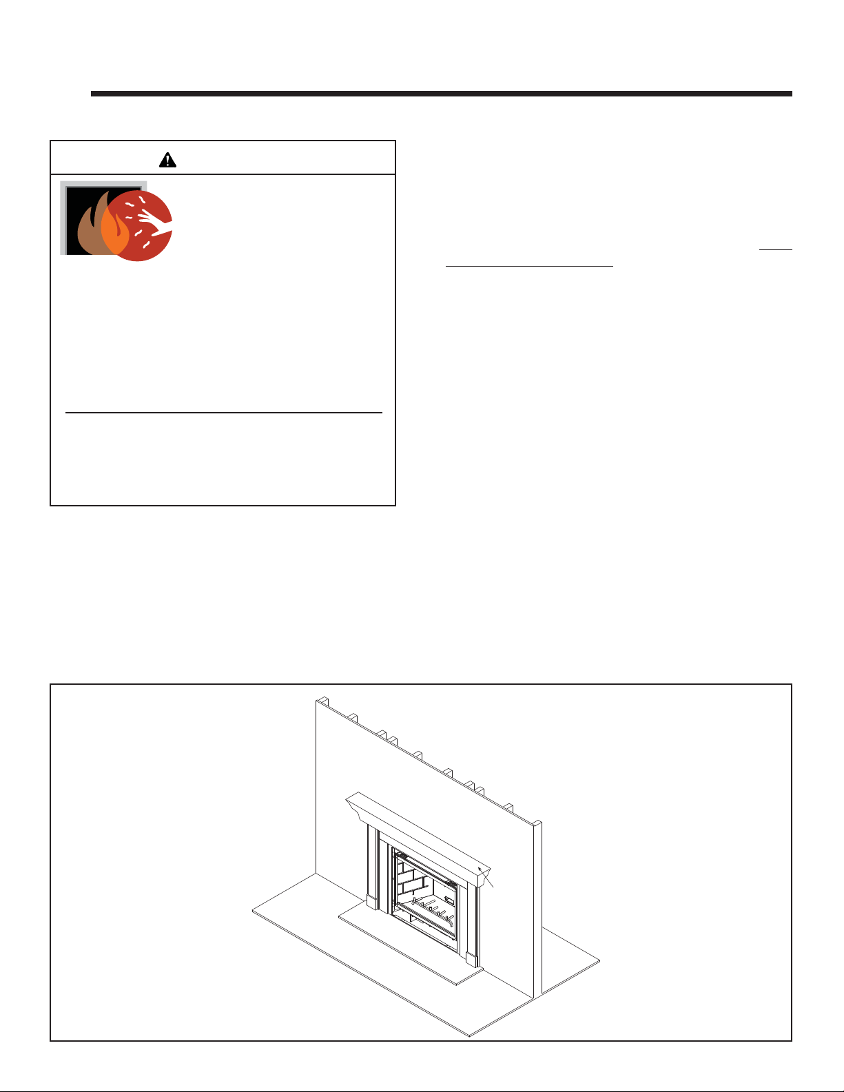
A. Gas Fireplace Safety
WARNING
HOT SURFACES!
Glass and other surfaces are hot during
operation AND cool down.
Hot glass will cause burns.
• DO NOT touch glass until it is cooled
• NEVER allow children to touch glass
• Keep children away
• CAREFULLY SUPERVISE children in same room as
fi replace.
• Alert children and adults to hazards of high temperatures.
High temperatures may ignite clothing or other
fl ammable materials.
• Keep clothing, furniture, draperies and other fl ammable
materials away.
This appliance has been supplied with an integral barrier
to prevent direct contact with the fi xed glass panel. DO
NOT operate the appliance with the barrier removed.
Contact your dealer or Hearth & Home Technologies if the
barrier is not present or help is needed to properly install one.
• Keep remote controls out of reach of children.
• Never leave children alone near a hot fi replace, whether
operating or cooling down.
• Teach children to NEVER touch the fi replace.
• Consider not using the fi replace when children will be
present.
Contact your dealer for more information, or visit: www.
hpba.org/safety-information.
T o prevent unintended operation when not using your fi re-
place for an extended period of time (summer months,
vacations, trips, etc):
• Remove batteries from remote controls.
• Turn off wall controls.
• Unplug 3 volt adapter plug and remove batteries on IPI
models.
If you expect that small children or vulnerable adults may
come into contact with this fi replace, the following precau-
tions are recommended:
• Install a physical barrier such as:
- A decorative fi rescreen.
- Adjustable safety gate.
• Install a switch lock or a wall/remote control with child
protection lockout feature.
DECORATIVE DOORS
(NOT SHOWN)
SECTION 2.E.
FIXED GLASS ASSEMBLY
GRATE
SECTION 2.B.
FAN KIT
SECTION 2.C
B. Your Fireplace
WARNING! DO NOT operate fi replace before read-
ing and understanding operating instructions. Failure
to operate fi replace according to operating instructions
could cause fi re or injury.
(NOT SHOWN)
SECTION 11.G.
MANTEL
Figure 2.1 Generic Operating Parts
CLEAR SPACE
SECTION 2.D.
HEARTH
9Outdoor Lifestyles by Hearth & Home Technologies, Inc. • Twilight-II-B • 2108-900 Rev. Z • 9/12
Page 10
C. Fan Kit (optional)
If desired, a fan kit may be added. Contact your dealer to
order the correct fan kit.
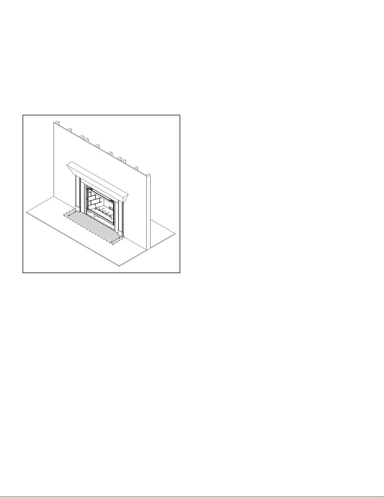
D. Clear Space
WARNING! DO NOT place combustible objects in front
of the fi replace or block louvers. High temperatures may
start a fi re. See Figure 2.2.
A void placing candles and other heat-sensitive objects on
mantel or hearth. Heat may damage these objects.
3 FT. IN FRONT OF FIREPLACE
CLEAR SPACE
Figure 2.2 Clear Space
F. Fixed Glass Assembly
See Section 11.G.
G. Remote Controls, Wall Controls and Wall
Switches
Follow the instructions supplied with the control installed
to operate your fi replace:
For safety:
• Install a switch lock or a wall/remote control with child
protection lockout feature.
• Keep remote controls out of reach of children.
See your dealer if you have questions.
H. Before Lighting Fireplace
Before operating this fi replace for the fi rst time, have a
qualifi ed service technician:
• Verify all shipping materials have been removed from
inside and/or underneath the fi rebox.
• Review proper placement of logs, ember material and/or
other decorative materials.
• Check the wiring.
• Check the air shutter adjustment.
• Ensure that there are no gas leaks.
• Ensure that the glass is sealed and in the proper position
and that the integral barrier is in place.
WARNING! Risk of Fire or Asphyxiation! DO NOT operate fi replace with fi xed glass assembly removed.
E. Decorative Doors and Fronts
WARNING! Risk of Fire! Install ONLY doors or fronts
approved by Hearth & Home Technologies. Unapproved
doors or fronts may cause fi replace to overheat.
This fireplace has been supplied with an integral
barrier to prevent direct contact with the fi xed glass
panel. DO NOT operate the fi replace with the barrier
removed.
Contact your dealer or Hearth & Home Technologies if
the barrier is not present or help is needed to properly
install one.
For more information refer to the instructions supplied with
your decorative door or front.
10
Outdoor Lifestyles by Hearth & Home Technologies, Inc. • Twilight-II-B • 2108-900 Rev. Z • 9/12
Page 11
I. Lighting Instructions (IPI)
The IPI system may be operated with two D-cell batteries. When using batteries, unplug the transformer. To prolong battery
life, remove them when using the transformer.
FOR YOUR SAFETY
READ BEFORE LIGHTING
WARNING: If you do not follow these instructions exactly, a fi re or explosion
may result causing property damage, personal injury or loss of life.
A. This appliance is equipped with an
intermittent pilot ignition (IPI) device
which automatically lights the burner. DO NOT try to light the burner by
hand.
B. BEFORE LIGHTING, smell all around
the appliance area for gas. Be sure to
smell next to the fl oor because some
gas is heavier than air and will settle
on the fl oor.
WHA T TO DO IF YOU SMELL GAS
• DO NOT try to light any appliance.
• DO NOT touch any electric switch; do
not use any phone in your building.
WARNING:
DO NOT CONNECT LINE VOLTAGE (110/120 VAC OR 220/240
V AC) TO THE CONTROL V ALVE.
Improper installation, adjustment, alteration, service or maintenance can
cause injury or property damage. Refer to the owner’s information manual
provided with this appliance.
This appliance needs fresh air for
safe operation and must be installed
so there are provisions for adequate
combustion and ventilation air.
If not installed, operated, and maintained in accordance with the manufacturer’s instructions, this product could
expose you to substances in fuel or
fuel combustion which are known to the
State of California to cause cancer, birth
defects, or other reproductive harm.
Keep burner and control compartment
clean. See installation and operating
instructions accompanying appliance.
• Immediately call your gas supplier
from a neighbor’s phone. Follow the
gas supplier’s instructions.
• If you cannot reach your gas supplier, call the fi re department.
C. DO NOT use this appliance if any
part has been under water. Immediately call a qualifi ed service tech-
nician to inspect the appliance and
to replace any part of the control
system and any gas control which
has been under water.
CAUTION:
Hot while in operation. DO NOT touch.
Keep children, clothing, furniture, gasoline and other liquids having fl ammable
vapors away.
DO NOT operate the appliance with
fi xed glass assembly removed, cracked
or broken. Replacement of the fi xed
glass assembly should be done by a
licensed or qualifi ed service person.
NOT FOR USE
WITH SOLID FUEL
For use with natural gas and propane.
A conversion kit, as supplied by the
manufacturer, shall be used to convert
this appliance to the alternate fuel.
Also Certifi ed for Installation in a
Bedroom or a Bedsitting Room.
For assistance or additional information, consult a qualifi ed installer, ser-
vice agency or the gas supplier.
LIGHTING
INSTRUCTIONS (IPI)
1. This appliance is equipped with an ignition
device which automatically lights the burner.
DO NOT try to light the burner by hand.
GAS
VALVE
2. Wait fi ve (5) minutes to clear out any gas.
Then smell for gas, including near the fl oor. If
you smell gas, STOP! Follow “B” in the Safety
Information located on the left side of this label. If you do not smell gas, go to next step.
3. To light the burner:
Equipped with wall switch: Turn ON/OFF switch
to ON.
Equipped with remote or wall control: Press
ON or FLAME button.
Equipped with thermostat: Set temperature to
desired setting.
4. If the appliance does not light after three tries,
call your service technician or gas supplier.
TO TURN OFF
GAS TO APPLIANCE
1. Equipped with wall switch: Turn ON/OFF switch
to OFF.
Equipped with remote or wall control: Press
OFF button.
Equipped with thermostat: Set temperature to
lowest setting.
2. Service technician should turn off electric
power to the control when performing service.
593-913G
Hearth & Home Technologies fi replace, please refer to www.fi replaces.com.
For additional information on operating your
Final inspection by
11Outdoor Lifestyles by Hearth & Home Technologies, Inc. • Twilight-II-B • 2108-900 Rev. Z • 9/12
Page 12

J. After Fireplace is Lit
Initial Break-in Procedure
• The fi replace should be run three to four hours continu-
ously on high.
• Turn the fi replace off and allow it to completely cool.
• Remove fi xed glass assembly. See Section 11.G.
• Clean fi xed glass assembly. See Section 3.
• Replace the fi xed glass assembly and run continuously
on high an additional 12 hours.
This cures the materials used to manufacture the fi re-
place.
NOTICE! Open windows for air circulation during fi re-
place break-in.
• Some people may be sensitive to smoke and odors.
• Smoke detectors may activate.
K. Frequently Asked Questions
ISSUE SOLUTIONS
Condensation on the glass
Blue fl ames
Odor from fi replace
Film on the glass
Metallic noise
Is it normal to see the pilot fl ame burn
continually?
This is a result of gas combustion and temperature variations. As the fi replace warms, this
condensation will disappear.
This is a result of normal operation and the fl ames will begin to yellow as the fi replace is al-
lowed to burn for 20 to 40 minutes.
When fi rst operated, this fi replace may release an odor for the fi rst several hours. This is
caused by the curing of materials from manufacturing. Odor may also be released from fi nish-
ing materials and adhesives used near the fi replace. These circumstances may require ad-
ditional curing related to the installation environment.
This is a normal result of the curing process of the paint and logs. Glass should be cleaned
within 3 to 4 hours of initial burning. A non-abrasive cleaner such as gas appliance glass
cleaner may be necessary. See your dealer.
Noise is caused by metal expanding and contracting as it heats up and cools down, similar to
the sound produced by a furnace or heating duct. This noise does not affect the operation or
longevity of the fi replace.
In an intermittent pilot ignition system (IPI), the pilot fl ame should turn off when appliance is
turned off. Some optional control systems available with IPI models may allow pilot fl ame to
remain lit.
12
Outdoor Lifestyles by Hearth & Home Technologies, Inc. • Twilight-II-B • 2108-900 Rev. Z • 9/12
Page 13

3
3
Maintenance and Service
Any safety screen or guard removed for servicing must be
replaced prior to operating the fi replace.
When properly maintained, your fi replace will give you
many years of trouble-free service. We recommend annual service by a qualifi ed service technician.
A. Maintenance Tasks-Homeowner
Installation and repair should be done by a qualifi ed service
technician only. The fi replace should be inspected before
use and at least annually by a professional service person.
The following tasks may be performed annually by the
homeowner. If you are uncomfortable performing any of
the listed tasks, please call your dealer for a service appointment.
More frequent cleaning may be required due to lint from
carpeting or other factors. Control compartment, burner
and circulating air passageway of the fi replace must be
kept clean.
CAUTION! Risk of Burns! The fi replace should be turned
off and cooled before servicing.
Glass Cleaning
Frequency: Seasonally
By: Homeowner
Tools Needed: Protective gloves, glass cleaner, drop
cloth and a stable work surface.
CAUTION! Handle fi xed glass assembly with care.
Glass is breakable.
• Avoid striking, scratching or slamming glass
• Avoid abrasive cleaners
• DO NOT clean glass while it is hot
• Prepare a work area large enough to accommodate fi xed
glass assembly and door frame by placing a drop cloth
on a fl at, stable surface.
Note: Fixed glass assembly and gasketing may have residue that can stain carpeting or fl oor surfaces.
• Remove door or decorative front from fi replace and set
aside on work surface.
• See Section 11.G for instructions to remove fi xed glass
assembly.
• Clean glass with a non-abrasive commercially available
cleaner.
- Light deposits: Use a soft cloth with soap and water
- Heavy deposits: Use commercial fireplace glass
cleaner (consult with your dealer)
• Carefully set fi xed glass assembly in place on fi replace.
Hold glass in place with one hand and secure glass
latches with the other hand.
• Reinstall door or decorative front.
Doors, Surrounds, Fronts
Frequency: Annually
By: Homeowner
Tools needed: Protective gloves, stable work surface
• Assess condition of screen and replace as necessary.
• Inspect for scratches, dents or other damage and repair
as necessary.
• Check that louvers are not blocked.
• Vacuum and dust surfaces.
Remote Control
Frequency: Seasonally
By: Homeowner
Tools needed: Replacement batteries and remote con-
trol instructions.
• Locate remote control transmitter and receiver.
• Verify operation of remote. Refer to remote control
operation instructions for proper calibration and setup
procedure.
• Place batteries as needed in remote transmitters and
battery-powered receivers.
• Place remote control out of reach of children.
If not using your fi replace for an extended period of time
(summer months, vacations/trips, etc), to prevent unintended operation:
• Remove batteries from remote controls.
• Unplug 3 volt adapter plug on IPI models.
13Outdoor Lifestyles by Hearth & Home Technologies, Inc. • Twilight-II-B • 2108-900 Rev. Z • 9/12
Page 14

Exhaust Termination
Frequency: Seasonally
By: Homeowner
Tools needed: Protective gloves and safety glasses.
• Inspect exhaust termination for blockage or obstruction
such plants, bird nests, leaves, snow, debris, etc.
• Verify exhaust termination clearance to subsequent construction (building additions, decks, fences, or sheds).
See Section 6.
B. Maintenance Tasks-Qualifi ed Service
Technician
The following tasks must be performed by a qualifi ed ser-
vice technician.
Gasket Seal and Glass Assembly Inspection
Frequency: Annually
By: Qualifi ed Service Technician
T ools needed: Protective gloves, drop cloth and a stable
work surface.
• Inspect gasket seal and its condition.
• Inspect fi xed glass assembly for scratches and nicks that
can lead to breakage when exposed to heat.
• Confi rm there is no damage to glass or glass frame.
Replace as necessary.
• Verify that fi xed glass assembly is properly retained and
attachment components are intact and not damaged.
Replace as necessary.
Logs
Frequency: Annually
By: Qualifi ed Service Technician
Tools needed: Protective gloves.
• Inspect for damaged or missing logs. Replace as necessary . Refer to Section 11 for log placement instructions.
• Verify correct log placement and no fl ame impingement
causing sooting. Correct as necessary.
Firebox
Frequency: Annually
By: Qualifi ed Service Technician
Tools needed: Protective gloves, sandpaper, steel wool,
cloths, mineral spirits, primer and touch-up paint.
• Inspect for paint condition, warped surfaces, corrosion
or perforation. Sand and repaint as necessary.
• Replace fi replace if fi rebox has been perforated.
Control Compartment and Firebox Top
Frequency: Annually
By: Qualifi ed Service Technician
Tools needed: Protective gloves, vacuum cleaner, dust
cloths
• V acuum and wipe out dust, cobwebs, debris or pet hair.
Use caution when cleaning these areas. Screw tips that
have penetrated the sheet metal are sharp and should
be avoided.
• Remove all foreign objects.
• Verify unobstructed air circulation.
Burner Ignition and Operation
Frequency: Annually
By: Qualifi ed Service Technician
T ools needed: Protective gloves, vacuum cleaner, whisk
broom, fl ashlight, voltmeter, indexed drill bit set, and a
manometer.
• Verify burner is properly secured and aligned with pilot
or igniter.
• Clean off burner top, inspect for plugged ports, corrosion
or deterioration. Replace burner if necessary.
• Replace Glowing embers with new dime-size pieces.
DO NOT block ports or obstruct lighting paths. Refer to
Section 11 for proper ember placement.
• Verify batteries have been removed from battery backup IPI systems to prevent premature battery failure or
leaking.
• Check for smooth lighting and ignition carryover to all
ports. Verify that there is no ignition delay.
• Inspect for lifting or other fl ame problems.
• Verify air shutter setting is correct. See Section 11 for
required air shutter setting. Verify air shutter is clear of
dust and debris.
• Inspect orifi ce for soot, dirt and corrosion. Verify orifi ce
size is correct. See Service Parts List for proper orifi ce
sizing.
• Verify manifold and inlet pressures. Adjust regulator as
required.
• Inspect pilot fl ame pattern and strength. See Figure 3.1
for proper pilot fl ame pattern. Clean or replace orifi ce
spud as necessary.
• Inspect IPI fl ame sensing rod for soot, corrosion and
deterioration. Polish with fi ne steel wool or replace as
required.
• Verify that there is not a short in fl ame sense circuit by
checking continuity between pilot hood and fl ame sense
rod. Replace pilot as necessary. (IPI only)
14
Outdoor Lifestyles by Hearth & Home Technologies, Inc. • Twilight-II-B • 2108-900 Rev. Z • 9/12
Page 15

(Either cobrahead or SIT)
Figure 3.1 IPI Pilot Flame Pattern
15Outdoor Lifestyles by Hearth & Home Technologies, Inc. • Twilight-II-B • 2108-900 Rev. Z • 9/12
Page 16

4
4
Getting Started
Installer Guide
A. Design and Installation Considerations
Hearth & Home Technologies direct vent gas appliances
are designed to operate with all combustion air siphoned
from outside of the building and all exhaust gases expelled to the outside. No additional outside air source is
required.
The Twilight-II-B has been carefully engineered to provide a unique fi replace experience. Since it is different
than any other product on the market, care must be taken
when installing this appliance so that our customer does
not experience undesirable performance or conditions.
1. Install the appliance according to this Owner’s Guide
paying particular attention to fl ashing and sealing in-
structions.
2. In the cold northern climates pay attention to exposures and prevailing wind conditions when locating the
appliance, the same as you would for locating exterior
windows and doors.
The Twilight-II-B has the thermal characteristics of a high
quality window system. T emperatures near the appliance will
be cooler than what is realized with a fully insulated wall.
Operation of the appliance will eliminate any cool drafts
and will provide the room with a comfortable ambiance.
Installation MUST comply with local, regional, state and
national codes and regulations. Consult insurance carrier,
local building inspector, fi re offi cials or authorities having
jurisdiction over restrictions, installation inspection and
permits.
Before installing, determine the following:
• Where the appliance is to be installed.
• Gas supply piping requirements.
• Electrical wiring requirements.
• Framing and fi nishing details.
• Whether optional accessories—devices such as a fan,
wall switch, or remote control—are desired.
Improper installation, adjustment, alteration, service or
maintenance can cause injury or property damage. For
assistance or additional information, consult a qualifi ed
service technician, service agency or your dealer.
B. Tools and Supplies Needed
Before beginning the installation be sure that the following
tools and building supplies are available.
Tape measure Framing material
Pliers High temperature caulking material
Hammer Phillips screwdriver
Gloves Framing square
Voltmeter Electric drill and bits (1/4 in.)
Plumb line Safety glasses
Level Reciprocating saw
Manometer Flat blade screwdriver
Non-corrosive leak check solution
1/2 - 3/4 in. length, #6 or #8 Self-drilling screws
One 1/4 in. female connection (for optional fan).
C. Inspect Appliance and Components
• Carefully remove the appliance and components from
the packaging.
• The vent system components and decorative doors and
fronts may be shipped in separate packages.
• If packaged separately, the log set and appliance grate
must be installed.
• Report to your dealer any parts damaged in shipment,
particularly the condition of the glass.
• Read all of the instructions before starting the instal-
lation. Follow these instructions carefully during the
installation to ensure maximum safety and benefi t.
WARNING! Risk of Fire or Explosion! Damaged parts
could impair safe operation. DO NOT install damaged, in-
complete or substitute components. Keep appliance dry.
Hearth & Home T echnologies disclaims any responsibility for ,
and the warranty will be voided by, the following actions:
• Installation and use of any damaged appliance or vent
system component.
• Modifi cation of the appliance or vent system.
• Installation other than as instructed by Hearth & Home
Technologies.
• Improper positioning of the gas logs or the glass door.
• Installation and/or use of any component part not approved
by Hearth & Home Technologies.
Any such action may cause a fi re hazard.
16
WARNING! Risk of Fire, Explosion or Electric Shock!
DO NOT use this appliance if any part has been under
water. Call a qualifi ed service technician to inspect the
appliance and to replace any part of the control system
and/or gas control which has been under water.
Outdoor Lifestyles by Hearth & Home Technologies, Inc. • Twilight-II-B • 2108-900 Rev. Z • 9/12
Page 17

5
5
Framing and Clearances
A. Selecting Appliance Location
When selecting a location for the appliance it is important to
consider the required clearances to walls (see Figure 5.1).
WARNING! Risk of Fire or Burns! Provide adequate
clearance around air openings and for service access.
Due to high temperatures, the appliance should be located out of traffi c and away from furniture and draperies.
GLASS
B
C*
NOTE: Appliance may be installed flush on exterior, interior or
anywhere in between. Any projection of the appliance interior
or exterior must have a properly constructed chase surrounding the appliance. The exterior must have proper insulating,
flashing and finishing to ensure an insulated envelope.
GLASS
A
NOTICE: Illustrations refl ect typical installations and are
FOR DESIGN PURPOSES ONLY. Illustrations/diagrams
are not drawn to scale. Actual installation may vary due to
individual design preference.
WARNING! Risk of Fire! The exterior side of the TWILIGHT-II-B CANNOT be recessed into the framing.
EXTERIOR INSULATED ENVELOPE
B
C* = 0 INCH (MIN.)
WARNING! Risk of Fire! The exterior side of the TWILIGHT-II-B
CANNOT be recessed into the framing.
FLUSH TO INTERIOR
D
E
GLASS
C* = 24 INCH (MAX.)
GLASS
AB C* DE
Minimum Minimum Minimum Maximum Minimum -
Inches 43 1/2 0 24 36 43
Millimeters 1092 13 0 610 914 1092
* = C dimension may be any length from 0 to 24 inches.
B
FLUSH TO EXTERIOR INSULATED ENVELOPE
PROJECTION
Figure 5.1 Appliance Locations
17Outdoor Lifestyles by Hearth & Home Technologies, Inc. • Twilight-II-B • 2108-900 Rev. Z • 9/12
Page 18

H
K
G
F
J
I
INTERIOR
FRAMING
EXTERIOR
FRAMING
E
D
C
A
B
B. Clearances
NOTICE: Install appliance on hard metal or wood surfaces
extending full width and depth. DO NOT install directly
on carpeting, vinyl, tile or any combustible material other
than wood.
WARNING! Risk of Fire! Do not install appliance against
vapor barriers or exposed insulation. Prevent contact with
sagging or loose insulation.
• Locate and install appliance to all clearance specifi cations
in manual.
• The chase must be properly blocked to prevent blown
insulation or other combustibles from entering and
making contact with fi replace.
• Failure to maintain airspace may cause overheating and
a fi re.
Note: Verify that tabs on insulation bracket are in an upright
position.
Finishing Material Clearances
OVERHANG
FINISHING MATERIALS
A
SIDING
MINIMUM CLEARANCES
A 36 in. 12 in.
B 64-5/16 in. 35-5/16 in.
SIDING
Vinyl Non-vinyl
A
B
A
SIDING
Figure 5.2 Exterior View - Finishing Material Clearances
Note: Framing dimensions assume use of
1/2 inch thick wall covering materials on
exterior of framing only, and NO sheetrock
on interior of framing.
From top of hood to
ceiling (interior) or
overhang (exterior).
CLEARANCES TO COMBUSTIBLES:
ABCD E F G H IJK
Exterior
Rough
Opening
(Height)
Interior
Rough
Opening
(Height)
Rough
Opening
(Depth)
Rough
Opening
(Width)
Framing
for non-
combustible
material
Clearance
to Ceiling
(INTERIOR)
Clearance to Overhang
(EXTERIOR)
Non-Vinyl Vinyl
Combustible
Floor
Combustible
Flooring
Standoff
Height
Inside
Standoff
Height
Outside
Inches 47-5/8 41-1/4 23 44 46-1/8 35-3/4 35-5/16 64-5/16 0 0 3-3/8 9-1/2 1/2
mm 1210 1048 584 1118 1172 908 897 1634 0 0 86 241 13
Figure 5.3 Clearances to Combustibles
18
Outdoor Lifestyles by Hearth & Home Technologies, Inc. • Twilight-II-B • 2108-900 Rev. Z • 9/12
Sides of
Appliance
Page 19

C. Mantel and Wall Projections
MEASURED
FROM CORNER
TOP VIEW
FIREPLACE
HOOD
1/2 IN.
WARNING! Risk of Fire! Comply with all minimum clearances as specifi ed. Framing or fi nishing material closer than
the minimums listed must be constructed entirely of noncombustible materials (i.e., steel studs, concrete board, etc).
Combustible and Non-combustible
Mantels- Indoor only
CEILING
NON-COMBUSTIBLE BOARD
(SUPPLIED ON APPLIANCE)
INDOOR SIDE ONLY
12
11
HOOD
10
9
8
7
6
11-5/8
10-5/8
9-5/8
8-5/8
7-5/8
35-3/4
13-5/8
12-5/8
Figure 5.5 Clearances to a Combustible and/or Non-combustible
Indoor Mantel or Mantel Leg
Note: Measurements are in inches.
Figure 5.4 Clearances to a Combustible and/or Non-combustible
Indoor Mantel
19Outdoor Lifestyles by Hearth & Home Technologies, Inc. • Twilight-II-B • 2108-900 Rev. Z • 9/12
Page 20

6
6
D
E
L
FP
A
H
M
X
J or K
I
A
G
F
FP
FP
FP
FP
FP
B
B
B
Termination Locations
A. Appliance Opening Minimum Clearances
= AREA WHERE APPLIANCE IS NOT PERMITTED
= AIR SUPPLY INLET
X
= APPLIANCE OPENING
FP
M
P
R
(See Note 2)
N
FP
Q
A = 0 in ........................clearances above grade, veran-
(See Note 1)
da, porch, deck or balcony
B* = 12 in. .....................clearances to window or door
that may be opened, or to permanently closed window.
D = 35-5/16 in. (
non-vinyl)
64-5/16 in. (vinyl) ......vertical clearance to ventilated
soffi t located above the hood
within a horizontal distance of 2
feet (60 cm) from the center-line
of the hood
E = 35-5/16 in.
(non-vinyl)
64-5/16 in. (vinyl).. ....clearance to unventilated soffi t
F = 9 in. ......................clearance to outside corner
G* = 12 in ......................clearance to inside corner
H = 3 ft. (Canada) ........not to be installed above a gas
meter/regulator assembly within
3 feet (90 cm) horizontally from
the center-line of the regulator
I = 3 ft. ........................clearance to service regulator
vent outlet and electric service
* 36 in. minimum for vinyl windows or vinyl siding.
** a appliance shall not open directly above a sidewalk or paved
driveway which is located between two single family dwellings
and serves both dwellings.
*** only permitted if veranda, porch, deck or balcony is fully open
on a minimum of 2 sides beneath the fl oor, or if the screened
porch guidelines are followed.
NOTE 1: Local codes or regulations may require different clearances.
NOTE 2: Termination in an alcove space (spaces open only on
one side and with an overhang) are permitted with the dimensions
specifi ed for vinyl or non-vinyl siding and soffi ts. 1. There must be 3
feet minimum between terminations or between the appliance and
termination. 2. All mechanical air intakes within 10 feet of a termination must be a minimum of 3 feet below the appliance hood. 3.
All gravity air intakes within 3 feet of the appliance hood must be a
minimum of 1 foot below the termination.
This appliance is approved for installation onto screened porches
with the following guidelines:
Figure 6.1 Minimum Clearances for Appliance Opening
20
Outdoor Lifestyles by Hearth & Home Technologies, Inc. • Twilight-II-B • 2108-900 Rev. Z • 9/12
J = 9 in. (U.S.A.)
12 in. (Canada) .......clearance to non-mechani-
cal air supply inlet to building
or the combustion air inlet to
any other appliance
K = 3 ft. (U.S.A.)
6 ft. (Canada) ...........clearance to a mechanical
air supply inlet
L** = 54 in. .......................clearance above paved side-
(See Note 1)
walk or a paved driveway lo-
cated on public property
M***= 35-5/16 in. ...............clearance under veranda,
porch, deck, balcony or over-
hang
64-5/16 in. ..............vinyl
N = 12 in. ......................non-vinyl siding
36 in. ......................vinyl siding
P = 8 ft.
Minimum porch area: 96 square feet
Minimum ceiling height: 92 inches
Minimum two walls must be screened
Minimum top of screen height, side walls: 6 ft. 8 in.
Minimum screen area: 64 square feet
NOTE: There may be some odor and small amounts of soot
associated with venting the Twilight-II-B onto a screened
porch. Ensuring good cross draft ventilation and routine
maintenance of the appliance will maximize comfort and
cleanliness.
Page 21

7
7
METAL HEARTH STRIP
UNDER EDGE OF
APPLIANCE
Appliance Preparation
A. Removing Non-combustible Facing Ma-
terial Assembly
The non-combustible assembly is located on right-hand
side of appliance (when looking from outdoor side of
appliance).
CAUTION
Handle with care.
• Non-combustible material may be damaged if dropped.
• Hold non-combustible pieces in place.
• Remove and save two screws from upper bracket.
• Remove non-combustible pieces.
• Remove and save three screws from lower bracket.
• Discard brackets.
• Replace screws in holes where brackets were attached
to appliance.
CAUTION
Handle with care.
• Avoid damaging protruding edges on outdoor side of ap-
pliance.
B. Securing and Leveling the Appliance
Figure 7.1 Positioning the Metal Hearth Strip
APPLIANCE
EXTERIOR
WARNING
Fire Risk.
• Prevent contact with sagging, loose
insulation.
• Do NOT install against vapor barriers or
exposed insulation.
Placing Metal Hearth Strip
The metal hearth strip (approximately 46 inches x 4 inches)
is used to provide added protection where appliance and
outer structure meet.
• Place a generous bead of silicone caulk into the corner
of the protective hearth strip.
• Place the metal strip onto the structure where the outer
edge of the appliance will sit (see Figure 7.1). It should
overlap building paper to prevent water infi ltration.
21Outdoor Lifestyles by Hearth & Home Technologies, Inc. • Twilight-II-B • 2108-900 Rev. Z • 9/12
Page 22

FIREPLACE
FLANGE
APPLY HIGH
TEMPERATURE
SILICONE SEALANT
TO CORNER EDGES
BEND IN
FLANGE
Placing and Securing Appliance
Place the appliance into position. Make sure fl ashing edges
on the outdoor surround fi t up tight to the framing.
The diagram shows how to properly position, level, and
secure the appliance (see Figure 7.2). Nailing tabs are provided to secure the appliance to the framing members.
• Caulk behind fl anges before securing to framing.
• Place the appliance into position.
• Level the appliance from side to side and front to
back.
• Shim the appliance as necessary. It is acceptable to
use wood shims.
• Keep nailing tabs fl ush with the framing.
• Secure the appliance to the framing by using nails or
screws through the nailing tabs.
Figure 7.3
Install outdoor fl ashing header (sheet metal piece removed
from shipping pallet). Place over upper portion of shroud
fl ange. Line up holes on shroud sides (see Figure 7.4).
SLIDE OUTDOOR FLASHING
DOWNWARD INTO POSITION
SECURE TO
FRAMING IN A MINIMUM
3 PLACES PER SIDE
NOTE: The exterior side of the appliance can protrude
outward. It MUST NOT be recessed into the framing. Caulk
behind all fl anges before securing to the exterior.
Figure 7.2 Proper Positioning, Leveling and Securing of a Appliance
Do NOT notch into the framing around the appliance spacers.
APPLIANCE
EXTERIOR
CAUTION
SECURE TO
FRAMING
HEADER
FLASHING
(INSTALLED
CORRECTLY)
SCREW
LOCATIONS
Figure 7.4
Seal fl ashing to exterior of building using high tempera-
ture caulk. Attach to building using holes provided on the
top of the left and right sides of outdoor fl ashing (see Fig-
ure 7.4).
Placing Flashing and Sheathing
Apply high temperature silicone sealant to corner edges
of fi replace fl ange (see Figure 7.3).
22
Outdoor Lifestyles by Hearth & Home Technologies, Inc. • Twilight-II-B • 2108-900 Rev. Z • 9/12
Page 23

Apply housewrap or building paper
APPLIANCE
TL-TRIM KIT
HOOD
TOP HOOD
TOP OF
FIREPLACE
16-5/16 in.
WALL STUD
HOUSEWRAP
INSULATION
HOUSEWRAP
**
(BUILDING
PAPER) OVERLAP
FLASHING 1 in.
SHEATHING,
COMBUSTIBLE
FIREPLACE
HEADER
INSULATED
FRAMING
STANDOFF
NON-COMBUSTIBLE
*
SHEATHING
10-7/8 in.
FLASHING
HEADER
10-7/8 in.
= NON-COMBUSTIBLE ZONE
2-3/4 in.
2-3/4 in.
= SHEATHING
= 1 INCH HOUSEWRAP OVERLAP
FLASHING
SHEATHING
NON-COMBUSTIBLE ZONE
For placement of combustible housewrap or building paper and non-combustible sheathing for the outside wall
see Figures 7.5 and 7.6.
Special care should be taken when choosing building
materials for weather proofi ng (i.e. building wraps, seal-
ant tapes, liquid sealants, rubberized fl ashings, etc.).
All sealant materials or building wraps installed within 6
inches of the top and 1 inch on the sides of the fi replace
surround must be approved to a minimum temperature
of 225º F continuous exposure. Consult the material’s
manufacturer to ensure product compliance.
TOP OF SURROUND
METAL FLASHING
6 IN.
* NOTE: All fi nishing materials on top of exterior sheathing
must be non-combustible for a minimum of 10-7/8 inches
above and 2-3/4 inches on both sides of the exterior face of
the appliance. This non-combustible fi nishing material can
be up to a maximum of 6 inches thick (6 inches maximum
horizontal overhang) to allow for brick and stone alcoves
(see Figure 10.5).
** NOTE: Combustible house wrap or building paper MUST
NOT extend over the outside of non-combustible sheath-
ing, and MAY extend over the fl ashing behind non-com-
bustible sheathing a maximum of 1 inch. Use high temp
silicone or sealant recommended by the manufacturer of
the housewrap to seal between combustible sheathing
house wrap and non-combustible sheathing. The sealant
material used within 6 inches of the top and 1 inch on the
sides of the fi replace surround must be approved to a
minimum temperature of 225º F continuous exposure.
Once the appliance is in place use enough high temperature silicone sealant or manufacturer specifi ed sealant
(approved to a minimum of 225º F) to make a water tight
seal between outdoor surround and exterior sheathing.
Face the perimeter of the appliance with non-combustible
sheathing over shroud fl anges and fl ashing. See Figure
7.7 for non-combustible zone.
SIDE OF SURROUND
Figure 7.5 Outside View without Non-combustible Sheathing Shown
Figure 7.6
1 IN.
Figure 7.7 Exterior Installation Prior to Finishing
WARNING
Risk of Fire
• Non-combustible clearances must be maintained.
• Sheetrock, wood or other combustibles must
NOT be used as sheathing or facing in the noncombustible zone.
• See Sections 5 and 10 for proper clearances.
• See Section 1 for combustible /non-combus-
tible defi nitions.
23Outdoor Lifestyles by Hearth & Home Technologies, Inc. • Twilight-II-B • 2108-900 Rev. Z • 9/12
Page 24

C. Installing Non-combustible Facing Mate-
Apply fasteners from
fastener packet
in these areas.
rial (Outdoor Side)
WARNING
Fire Risk.
• Follow these instructions exactly.
• Facing materials must be installed properly to
prevent fi re.
• No materials may be substituted
without authorization by Hearth & Home
Technologies.
• Attach the left and right side pieces to the framing members. (See Figure 7.9).
NON-COMBUSTIBLE
FACING MATERIAL
• Center and attach two top boards (the two shorter pieces)
to the framing members. See Figure 7.8.
• Use fasteners from fastener packet (in manual bag) in
shaded areas (see Figure 7.8).
• Use regular sheetrock screws in non-shaded areas.
48-5/8 in.
47-5/8 in.
Figure 7.9 Complete Installation of Non-combustible
Facing Material (Outdoor Side)
• Use a wet or dry towel or soft brush to remove dust or
dirt from facing material.
• Apply a non-combustible adhesive to attach tile, stone
or other non-combustible fi nishing materials per manu-
facturer’s instructions.
Figure 7.8 Attaching Non-combustible Facing Material
(Outdoor Side Only)
24
Outdoor Lifestyles by Hearth & Home Technologies, Inc. • Twilight-II-B • 2108-900 Rev. Z • 9/12
Page 25

8
8
Gas Information
A. Fuel Conversion
• Make sure the appliance is compatible with available gas
types.
• Conversions must be made by a qualified service
technician using Hearth & Home T echnologies specifi ed
and approved parts.
B. Gas Pressure
• Optimum appliance performance requires proper input
pressures.
• Gas line sizing requirements will be determined in ANSI
Z223.1 National Fuel Gas Code in the USA and CAN/
CGA B149 in Canada.
• Pressure requirements are:
Gas Pressure Natural Gas Propane
Minimum inlet pressure 5.0 in. w.c. 11.0 in. w.c.
Maximum inlet pressure 10.0 in. w.c. 13.0 in. w.c.
Manifold pressure 3.5 in. w.c. 10.0 in. w.c.
WARNING! Risk of Fire or Explosion! High pressure
will damage valve. Low pressure may cause explosion.
• Verify inlet pressures. Verify minimum pressures when
other household gas appliances are operating.
• Install regulator upstream of valve if line pressure is
greater than 1/2 psig.
WARNING
Fire Risk.
Explosion Hazard.
High pressure will damage valve.
• Disconnect gas supply piping BEFORE
pressure testing gas line at test pressures
above 1/2 psig.
• Close the manual shutoff valve BEFORE
pressure testing gas line at test pressures
equal to or less than 1/2 psig.
Note: Have the gas supply line installed in accordance with
local codes, if any. If not, follow ANSI 223.1. Installation
should be done by a qualifi ed installer approved and/or
licensed as required by the locality. (In the Commonwealth
of Massachusetts installation must be performed by a
licensed plumber or gas fi tter).
Note: A listed (and Commonwealth of Massachusetts approved) 1/2 in. (13 mm) T-handle manual shut-off valve
and fl exible gas connector are connected to the 1/2 in. (13
mm) control valve inlet.
• If substituting for these components, please consult
local codes for compliance.
C. Gas Connection
• Refer to Reference Section 13 for location of gas line
access in appliance.
• Gas line may be run through knockout(s) provided.
• The gap bet ween supply piping and gas access hole
may be caulked with high temperature caulk or stuffe d
with non-combustible, unfaced insulation to prevent cold
air infi ltration.
• Ensure that gas line does not come in contact with outer
wrap of the appliance. Follow local codes.
• Pipe incoming gas line into valve compartment.
• Connect incoming gas line to the 1/2 in. (13 mm)
connection on manual shutoff valve.
WARNING! Risk of Fire or Explosion! Support control
when attaching pipe to prevent bending gas line.
• A small amount of air will be in the gas supply lines.
WARNING! Risk of Fire or Explosion! Gas build-up dur ing line purge could ignite.
• Purge should be performed by qualified service
technician.
• Ensure adequate ventilation.
• Ensure there are no ignition sources such as sparks
or open fl ames.
Light the appliance. It will take a short time for air to purge
from lines. When purging is complete the appliance will
light and operate normally.
WARNING! Risk of Fire, Explosion or Asphyxiation!
Check all fi ttings and connections with a non-corrosive
commercially available leak-check solution. DO NOT use
open fl ame. Fittings and connections could have loos-
ened during shipping and handling.
WARNING! Risk of Fire! DO NOT change valve settings.
This valve has been preset at the factory.
D. High Altitude Installations
NOTICE: If the heating value of the gas has been reduced,
these rules do not apply. Check with your local gas utility
or authorities having jurisdiction.
When installing above 2000 feet elevation:
• In the USA: Reduce burner orifi ce 4% for each 1000 feet
above 2000 feet.
• In CANADA: Reduce burner orifi ce 10% for elevations
between 2000 feet and 4500 feet. Above 4500 feet,
consult local gas utility.
25Outdoor Lifestyles by Hearth & Home Technologies, Inc. • Twilight-II-B • 2108-900 Rev. Z • 9/12
Page 26

9
9
Electrical Information
A. Wiring Requirements
NOTICE: This appliance must be electrically wired
and grounded in accordance with local codes or, in the
absence of local codes, with National Electric Code
ANSI/NFPA 70-latest edition or the Canadian Electric
Code CSA C22.1.
• Wire the appliance junction box to 1 10-120 VAC. This is
required for proper operation of the appliance.
• A 1 10-120 V AC circuit for this product must be protected
with ground-fault circuit-interrupter protection, in
compliance with the applicable electrical codes, when
it is installed in locations such as in bathrooms or near
sinks.
• Low voltage and 110 VAC voltage cannot be shared
within the same wall box.
WARNING! Risk of Shock or Explosion! DO NOT wire
1 10V to the valve or to the appliance wall switch. Incorrect
wiring will damage controls.
NOTICE: Waterproof insulated wire should be used when
wiring the junction box.
B. Connecting to the Appliance
WARNING
Wire 110V to electrical junction box.
Do NOT wire 110V to valve.
Do NOT wire 110V to wall switch.
• Incorrect wiring will damage millivolt valves.
• Incorrect wiring will override IPI safety lockout
and may cause explosion.
• This appliance may be used with a wall switch, wall
mounted thermostat and/or a remote control.
• If using thermostat use one compatible with a millivolt
gas valve system.
• Follow parameters for locating thermostat (see individual
thermostat instructions) to ensure proper operation of
appliance.
• Keep wire lengths short as possible by removing any
excess wire length.
• Low voltage and 110 VAC voltage cannot be shared
within the same wall box.
26
Outdoor Lifestyles by Hearth & Home Technologies, Inc. • Twilight-II-B • 2108-900 Rev. Z • 9/12
Page 27

C. Intellifi re Ignition System Wiring
• Wire the appliance junction box to 110 VAC for proper
operation of the appliance.
WARNING! Risk of Shock or Explosion! DO NOT wire
IPI controlled appliance junction box to a switched circuit.
Incorrect wiring will override IPI safety lockout.
• Refer to Figure 9.1, Intellifi re Pilot Ignition (IPI) Wiring
Diagram.
• This appliance is equipped with an Intellifi re control valve
which operates on a 3 volt system.
• Plug the 3-volt AC transformer into the appliance junction
box to supply power to the unit OR install two D cell
batteries (not included) into the battery pack before use.
NOTICE: Batteries should not be placed in the battery
pack while using the transformer. Remove batteries before
using the transformer, and unplug the transformer before
installing the batteries. Battery polarity must be correct or
module damage will occur.
3V TRANSFORMER
ON/OFF
WALL
SWITCH
VALVE
NEUTRAL
BLACK WIRE CAN BE
PLUGGED INTO ANY OF
#1 - #5 LOCATIONS
ON THE HOT SIDE
PLUG-IN
IGNITION
MODULE
(3V)
LOW VOLTAGE
GROUND
FLAME SPARKER/
SENSOR
SEE NOTE 1
REMOTE
CONTROL
WHITE WIRE
CAN BE
PLUGGED
INTO ANY
OF #1-#5
LOCATIONS
ON THE
NEUTRAL SIDE
HOT
IGNITION MODULE
3 VAC
TRANSFORMER
3 VAC
BRN
PIGGYBACK
ON/OFF SWITCH
BRN
I
S
GROUND TO
FIREPLACE
CHASSIS
INTERMITTENT
PILOT
IGNITOR
WHT
ORG
ORG
GRN
NOTE: 1. Ignition module, valve, pilot, and wall switch operate on 3 volts.
Uninterrupted 120 VAC is required at junction box unless equipped with battery back-up.
Figure 9.1 Intellifi re Pilot Ignition (IPI) Wiring Diagram
PLUG IN
VALVE
27Outdoor Lifestyles by Hearth & Home Technologies, Inc. • Twilight-II-B • 2108-900 Rev. Z • 9/12
Page 28

D. Optional Accessories
FAN
DRIP
TRAY
Optional fan and remote control kits require that 110-120
VAC be wired to the factory installed junction box before
the appliance is permanently installed (see Figure 9.3).
Fan Installation
To provide best airfl ow, we recommend positioning fan
on the left side (as viewed from appliance interior side
(see Figure 9.2). NOTE: It is recommended fan be installed prior to gas line installation.
Wall Switch
Position the wall switch in the desired position on a wall.
Run a maximum of 25 feet (7.8 m) or less length of 18
A.W.G. minimum wire and connect it to the appliance ON/
OFF switch pigtails.
FAN SPEED
CONTROL
(RHEOSTAT)
6 FT.
APPROX.
WIRE LEAD
1 MALE END
1 FEMALE END
APPLIANCE
INTERIOR
SIDE
Figure 9.2 Fan location
DETAIL A
PLUG AND WIRE
ASSEMBLY
Figure 9.3 Fan Wiring Diagram
FAN KIT
#GFK-160T
6 FT.
APPROX.
TEMPERATURE
SENSOR SWITCH
WIRE LEAD
2 FEMALE ENDS
JUNCTION BOX
SEE DETAIL A
NOTE: If any of the original wire as supplied
with the appliance must be replaced, it must be
replaced with the type 105oC rated wire.
28
Outdoor Lifestyles by Hearth & Home Technologies, Inc. • Twilight-II-B • 2108-900 Rev. Z • 9/12
Page 29

GREEN WIRE
INSIDE BOX
14/2WG
COPPER GROUND
ATTACHED TO GRN SCREW
WITH GRN WIRE
BLK
WHT
WHT
BLK
HEAT SHIELD
E. Junction Box Installation
If the box is being wired from the OUTSIDE of the
appliance:
• Install the Romex™ connector (not included with
appliance) in the side wrap.
• Loosen two screws on the Romex connector, feed
the necessary length of wire through the connector
and tighten the screws.
• Make all necessary wire connections.
If the box is being wired from the INSIDE of the
appliance:
• Remove the screw attaching the junction box to
the outer shell, rotate the junction box inward to
disengage it from the outer shell (see Figure 9.4).
• Pull the electrical wires from outside the appliance
through this opening into the valve compartment.
NOTE: Do NOT wire
110 VAC to wall switch.
Figure 9.4 Junction Box Detail
• Loosen the two screws on the Romex connector, feed the
necessary length of wire through the connector and tighten the
screws.
• Make all necessary wire connections to the receptacle and
assemble the receptacle and cover to the junction box.
F. Wall Switch Installation for Fan (Optional)
If the box is being wired to a wall mounted switch for use
with a fan (See Figure 9.5):
• The power supply for the appliance must be brought into
a switch box.
• The power can then be supplied from the switch box to the
appliance using a minimum of 14-3 with ground wire.
• At the switch box connect the black (hot) wire and red
(switch leg) wire to the wall switch as shown.
• At the appliance connect the black (hot), white (neutral)
and green (ground) wires to the junction box as shown.
• Add a 1/4 in. insulated female connector to the red (switch
leg) wire, route it through the knockout in the face of the
junction box, and connect to the top fan switch connector
(1/4 in. male) as shown.
Minimum 14-3 AWG
with Ground
Junction Box
Red
Figure 9.5 Junction Box Wired to Wall Switch or BC10
Red
White
Black
Red
Black
Green
White
Green
Switch Box
Knockout
Black
White
Green
Switch
Power
Supply
Wires
29Outdoor Lifestyles by Hearth & Home Technologies, Inc. • Twilight-II-B • 2108-900 Rev. Z • 9/12
Page 30

10
10
MEASURED
FROM CORNER
TOP VIEW
FIREPLACE
HOOD
1/2 IN.
41-7/8 in.
2-3/4 in.
NON-COMBUSTIBLE ZONE
Finishing
A. Mantel and Wall Projections
WARNING! Risk of Fire! Comply with all minimum clearances as specifi ed. Framing closer than the minimums list-
ed must be constructed entirely of noncombustible materials (i.e., steel studs, concrete board, etc.) Failure to comply
could cause fi re.
CEILING
NON-COMBUSTIBLE BOARD
(SUPPLIED ON APPLIANCE)
INDOOR SIDE ONLY
12
11
HOOD
10
9
8
7
6
11-5/8
10-5/8
9-5/8
8-5/8
7-5/8
35-3/4
13-5/8
12-5/8
B. Facing Material
Inside Facing Material
• May install combustible materials up to specified
clearances on top, front and sides of appliance.
• Seal joints between fi nished wall and appliance top and
sides with 300ºF (140º C) minimum sealant.
• Leave space so bottom grille can be lowered for trim
door removal.
WARNING! Risk of Fire! DO NOT apply combustible
materials beyond the minimum clearances. Comply with
all minimum clearances to combustibles as specifi ed in
this manual. Overlapping materials could ignite and will
interfere with proper operation of doors and louvers.
Note: Measurements are in inches.
Figure 10.1 Clearances to a Combustible and/or Non-combustible
Figure 10.2 Clearances to a Combustible and/or Non-combustible
30
Indoor Mantel
Indoor Mantel or Mantel Leg
Outdoor Lifestyles by Hearth & Home Technologies, Inc. • Twilight-II-B • 2108-900 Rev. Z • 9/12
Figure 10.3 Non-combustible Zone (Interior)
Finishing Material Clearances
OVERHANG
FINISHING MATERIALS
A
SIDING
SIDING
MINIMUM CLEARANCES
Vinyl Non-vinyl
A 36 in. 12 in.
B 64-5/16 in. 35-5/16 in.
Figure 10.4 Exterior View - Finishing Material Clearances
A
A
SIDING
B
Page 31

2-3/4 IN.
10-7/8 in.
HOOD
NON-COMBUSTIBLE
SHEATING
6 in.
MAX.
NON-COMBUSTIBLE
FACING
THERE MUST BE NO GAP
BETWEEN BRICK LEDGE,
FACING MATERIAL AND
APPLIANCE FRONT
6 in. MAXMUM PROJECTION
FROM FACE OF FIREPLACE
BRICK LEDGE
NON-COMBUSTIBLE
SHEATHING (SUPPLIED)
COMBUSTIBLE
SHEATHING
HOUSEWRAP
REQUIRED
FLASHING
(SUPPLIED)
HOUSE
WRAP
WARNINGWARNING
Risk of Fire
• Non-combustible clearances must be
maintained.
• Sheetrock, wood or other combustibles must NOT
be used as sheathing or facing in the noncombustible zone.
• See Sections 5 & 10 for proper clearances.
• See Section 1 for combustible/non-
combustible defi nitions.
May install non-combustible materials to cover gap between facing material and appliance (see Figure 10.5).
WARNING
Fire Risk.
Water Intrusion Risk.
Hood is required.
• Flashing and non-combustible sheathing must be
installed before facing materials.
• Facing must be non-combustible and seal tight to
fi replace front.
Fire Risk.
Finish all edges and fronts to clearances
and specifi cations listed in manual.
• Black metal columns may be covered with
non-combustible material only.
• Do NOT overlap combustible materials onto appliance
front.
• Install combustible materials only up to specified
clearances on top, front and side edges.
• Seal joints between the fi nished wall and appliance top
and sides using only a 300º
F minimum sealant.
Figure 10.5 Exterior View
31Outdoor Lifestyles by Hearth & Home Technologies, Inc. • Twilight-II-B • 2108-900 Rev. Z • 9/12
Page 32

APPLIANCE
HOOD
TOP OF
APPLIANCE
SOFFIT
SIDING
HOUSEWRAP (BUILDING
PAPER) AND SHEA THING
35-5/16 in.
MINIMUM CLEARANCE
TO NON-VINYL
64-5/16 in.
CLEARANCE TO VINYL
SOFFIT, OVERHANG, MANTEL,
OR CEILING
12 in.
MINIMUM CLEARANCE
TO NON-VINYL SIDING
36 in. MINIMUM
CLEARANCE TO VINYL SIDING
DRAIN PLANE
DETERMINED BY
LOCAL CODE
BRICK OR OTHER NON-COMBUSTIBLE
FACING MATERIAL 6 INCH MAXIMUM
PROJECTION FROM SURFACE OF
FIREPLACE (INCLUDES NON-COMBUSTIBLE
MANTEL PROJECTION)
NON-COMBUSTIBLE BRICK LEDGE
MUST BE TIGHT TO APPLIANCE
FACE OR NON-COMBUSTIBLE SHEATHING
TOP OF HOOD
INSULATION
NOTE: All fi nishing materials on top of exterior
APPLIANCE
HOOD
TOP HOOD
TOP OF
FIREPLACE
10-7/8 in.
CEILING OR OVERHANG
64-5/16 in.
MINIMUM CLEARANCE
TO VINYL SOFFIT,
CEILING OR OVERHANG.
35-5/16 in.
MINIMUM CLEARANCE TO
NON-VINYL SOFFIT, MANTEL,
CEILING OR OVERHANG.
STUD WALL
SOFFIT
HOUSEWRAP
INSULATION
HOUSEWRAP
(BUILDING
PAPER) OVERLAP
FLASHING 1 in.
SHEATHING,
COMBUSTIBLE
FIREPLACE
HEADER
INSULATED
FRAMING
STANDOFF
NON-COMBUSTIBLE
SHEATHING
FLASHING
HEADER
sheathing must be non-combustible for a minimum
of 10-7/8 inches above and on both sides of
the exterior face of the appliance. This noncombustible fi nishing material can be up to a
maximum of 6 inches thick (6 inches maximum
horizontal overhang) to allow for brick and stone
alcoves (see Figure 8.5).
NOTE: Combustible housewrap or building
paper MUST NOT extend over the outside of
non-combustible sheathing, and MAY extend
over the fl ashing header behind non-combustible
sheathing. Use high temp caulk to seal between
combustible sheathing housewrap and noncombustible sheathing.
Figure 10.6 Exterior View
DETAIL -
SEE FIGURE 10.5
Figure 10.7 Exterior View with Non-combustible Facing Material
32
Outdoor Lifestyles by Hearth & Home Technologies, Inc. • Twilight-II-B • 2108-900 Rev. Z • 9/12
Page 33

11
11
Appliance Setup
A. Remove Fixed Glass Assembly
See Section 11.G.
B. Remove the Shipping Materials
Remove shipping materials from inside or underneath the
fi rebox.
C. Clean the Appliance
Clean/vacuum any sawdust that may have accumulated
inside the fi rebox or underneath in the control cavity.
D. Accessories
Install approved accessories per instructions included
with accessories. Contact your dealer for a list of approved accessories.
WARNING! Risk of Fire and Electric Shock! Use ONLY
Hearth & Home Technologies-approved optional accessories with this appliance. Using non-listed accessories
could result in a safety hazard and will void the warranty.
E. Lava Rock and Ember Placement
WARNING! Risk of Explosion! Follow ember placement
instructions in manual. DO NOT place embers directly over
burner ports. Replace ember material annually . Improperly
placed embers interfere with proper burner operation.
Placing Lava Rock
Place lava rock on refractory support pan. Cover entire
support pan surface (see Figure 11.1).
Figure 11.1 Placement of Lava Rock
Placing the Ember Material
Ember material is shipped with this gas appliance. T o place
the ember material:
• Embers CANNOT be placed directly over ports.
• When placing Glowing Embers
should be taken so that the ports are not covered. Place
the dime-size ember pieces just in front of the port trail,
but not on or in between the ports (see Figure 11.2).
Failure to follow this procedure will likely cause lighting
and sooting problems.
®
onto the burner care
Figure 11.2 Placement of Ember Materials
• Save the remaining ember materials for use during
appliance servicing. The embers provided should be
enough for 3 to 5 applications.
33Outdoor Lifestyles by Hearth & Home Technologies, Inc. • Twilight-II-B • 2108-900 Rev. Z • 9/12
Page 34

F. Install the Log Assembly
1
2
PILOT
ASSEMBLY
CUTOUT
GRATE BAR CUTOUT
1-inch
1
1
2
4
5
6
3
PILOT ASSEMBLY
INDENT
BACK VIEW
BOTTOM VIEW
GRATE TINE (HIDDEN)
GRATE
BAR
INDENT
4
3
5
2
1
6
Log Set Assembly: LOGS-MSR
PILOT ASSEMBL Y
CAUTION: Logs are fragile! Carefully remove the logs
from the packaging. Remove the cardboard support from
inside of fi replace.
INDENT
BOTTOM VIEW
INDENT
BACK VIEW
STEP 2. LOG #1 (SRV2005-701): Use the indent on the bottom side of the log to position the large end of the log onto
the grate bar as shown. Slide the log back until the indent engages the grate tine as shown above. Position the thin end of
log #1 one inch from port pattern as shown.
GRATE BAR CUTOUT
STEP 1. Before positioning the logs, refer to the installation
manual for electric ember set-up and ember placement.
GRATE TINE (HIDDEN)
1
GRATE
BAR
1-inch
1
2
PILOT
ASSEMBLY
CUTOUT
STEP 3. LOG #2 (SRV2005-700): Position log #2 on the left grate bar and the pilot assembly. Use the cut out notches
on the log to position it as shown.
34
Outdoor Lifestyles by Hearth & Home Technologies, Inc. • Twilight-II-B • 2108-900 Rev. Z • 9/12
2005-937F
Page 35

3
4
SHARP
NOTCH
SHARP
NOTCH
2
2
1
3
2
1
4
5
3
2
1
GRATE
TINE
3/4 IN.
3
STEP 4. LOG #3 (SR V2005-702): Position log #3 as shown by leaning it against log # 2 and resting the other end on the
peak of the burner. DO NOT cover any port holes.
3/4 IN.
4
3
2
1
1
SHARP
NOTCH
STEP 5. LOG #4 (SRV2005-703): Locate the sharp notch on log #4 against the grate tine as shown. The smooth cutout
on the bottom of log #4 should rest on the burner surface. The side of Log #4 must be 3/4 inch from the nearest port hole
on the right side of log #4. DO NOT cover any port holes.
1
SHARP
NOTCH
3
2
2
GRATE
TINE
5
4
1
STEP 6. LOG #5 (SRV2005-704): Using the sharp notch on the heavy end of log #5, align it on the grate tine and set it
on the fl at area of log #4 as shown.
35Outdoor Lifestyles by Hearth & Home Technologies, Inc. • Twilight-II-B • 2108-900 Rev. Z • 9/12
Page 36

6
5
4
3
2
1
4
5
3
2
1
FLAT AREA
FLA T AREA
Notch
Notch engaged with
grate tine.
1
4
Notch
3
2
5
1
2
STEP 7. LOG #6 (SRV2005-705): Locate the notch on log #6 and place it against the front right grate tine. Set the
other end of the log so it rests on the fl at area of log #1. The orientation of log #6 in relation to the grate tine is shown
below.
3
2
Log Assembly Installed.
5
4
6
Notch engaged with
grate tine.
1
36
Outdoor Lifestyles by Hearth & Home Technologies, Inc. • Twilight-II-B • 2108-900 Rev. Z • 9/12
Page 37

G. Fixed Glass Assembly
WARNING! Risk of Asphyxiation! Handle fi xed glass
assembly with care. Inspect the gasket to ensure it is
undamaged and inspect the glass for cracks, chips or
scratches.
• DO NOT strike, slam or scratch glass.
• DO NOT operate fi replace with glass removed, cracked,
broken or scratched.
• Replace as a complete assembly.
Removing Fixed Glass Assembly
• Remove wing nuts and glass clips around glass door.
Remove glass door from the appliance.
Replacing Fixed Glass Assembly
• Replace the glass door on the appliance.
H. Install Trim and/or Surround
• Install optional trim kits and/or surrounds using the
instructions included with the accessory.
• Use non-combustible materials to cover the gap between
the sheet rock and the appliance (when applicable to the
model).
I. Air Shutter Setting
Air shutter settings should be adjusted by a qualifi ed ser-
vice technician at the time of installation. The air shutter
is set at the factory for minimum vertical vent run. Adjust
air shutter for longer vertical runs.
NOTICE: If sooting occurs, provide more air by opening
the air shutter.
Air Shutter Settings
NG LP
Twilight-II-B 3/8 in. Full Open
37Outdoor Lifestyles by Hearth & Home Technologies, Inc. • Twilight-II-B • 2108-900 Rev. Z • 9/12
Page 38

12
12
Troubleshooting
With proper installation, operation, and maintenance your gas appliance will provide years of trouble-free service. If you do
experience a problem, this troubleshooting guide will assist a qualifi ed service technician in the diagnosis of a problem and
the corrective action to be taken. This troubleshooting guide can only be used by a qualifi ed service technician. Contact
your dealer to arrange a service call by a qualifi ed service technician.
A. Intellifi re Ignition System
Symptom Possible Cause Corrective Action
1. Pilot won’t light.
The ignitor/module
makes noise, but no
spark.
2. Pilot won’t light,
there is no noise or
spark.
A. Incorrect wiring. Verify “S” wire (white) for sensor and “I” wire (orange) for ignitor are
connected to correct terminals on module and pilot assembly.
B. Loose connections or electrical
shorts in the wiring.
C. Ignitor gap is too large. Verify gap of igniter to right side of pilot hood. The gap should be
D. Module. Turn ON/OFF rocker switch or wall switch to OFF position. Remove
A. No power or transformer installed
incorrectly.
B. A shorted or loose connection in
wiring confi guration or wiring har-
ness.
Verify no loose connections or electrical shorts in wiring from module to pilot assembly. Verify connections underneath pilot assembly are tight; also verify connections are not grounding out to metal
chassis, pilot burner, pilot enclosure, mesh screen if present, or any
other metal object.
approximately .17 in. or 1/8 in. (3 mm).
ignitor wire “I” from module. Place a grounded wire about 3/16 in. (5
mm) away from “I” terminal on module. Place ON/OFF rocker switch
or wall switch in ON position. If there is no spark at “I” terminal module
must be replaced. If there is a spark at “I” terminal, module is fi ne.
Inspect pilot assembly for shorted sparker wire or cracked insulator
around electrode. Replace pilot if necessary .
Verify that transformer is installed and plugged into module. Check
voltage of transformer under load at spade connection on module
with ON/OFF switch in ON position. Acceptable readings of a good
transformer are between 3.2 and 2.8 volts AC.
Remove and reinstall the wiring harness that plugs into module.
Verify there is a tight fi t. Verify pilot assembly wiring to module. Re-
move and verify continuity of each wire in wiring harness. Replace
any damaged components.
3. Pilot sparks, but
Pilot will not light.
38
C. Improper wall switch wiring. Verify that 110/VAC power is “ON” to junction box.
D. Module not grounded. Verify black ground wire from module wire harness is grounded to
metal chassis of appliance.
E. Module. Turn ON/OFF rocker switch or wall switch to OFF position. Remove
ignitor wire “I” from module. Place ON/OFF rocker switch or wall
switch in ON position. If there is no spark at “I” terminal module
must be replaced. If there is a spark at “I” terminal, module is fi ne.
Inspect pilot assembly for shorted sparker wire or cracked insulator
around electrode.
A. Gas supply. Verify that incoming gas line ball valve is “open”. Verify that inlet
pressure reading is within acceptable limits.
B. Ignitor gap is too large. Verify gap of igniter to right side of pilot hood. The gap should be
approximately .17 in. or 1/8 in. (3 mm).
C. Module is not grounded. Verify module is securely grounded to metal chassis of appliance.
D. Module voltage output / Valve/Pilot
solenoid ohms readings.
Outdoor Lifestyles by Hearth & Home Technologies, Inc. • Twilight-II-B • 2108-900 Rev. Z • 9/12
Verify battery voltage is at least 2.7 volts. Replace batteries if volt-
age is below 2.7.
Page 39

Intellifi re Ignition System - (continued)
Symptom Possible Cause Corrective Action
4. Pilot lights but continues to spark, and main
burner will not ignite.
(If the pilot continues
to spark after the
pilot fl ame has been lit,
fl ame rectifi cation has
not occurred.)
A. A shorted or loose connection in fl ame
sensing rod.
B. Poor fl ame rectifi cation or contaminated
fl ame sensing rod.
C. Module is not grounded. Verify module is securely grounded to metal chassis of ap-
D. Damaged pilot assembly or contami-
nated fl ame sensing rod.
E. Module. Turn ON/OFF rocker switch or wall switch to OFF position.
Verify all connections to wiring diagram in manual. Verify
connections underneath pilot assembly are tight. Verify connections are not grounding out to metal chassis, pilot burner, pilot enclosure or screen if present, or any other metal
object.
With fi xed glass assembly in place, verify that fl ame is en-
gulfi ng fl ame sensing rod on left side of pilot hood. Flame
sensing rod
rect pilot orifi ce is installed and gas inlet is set to pressure
specifi cations. Polish fl ame sensing rod with fi ne steel wool
to remove any contaminants that may have accumulated on
fl ame sensing rod.
pliance. Verify that wire harness is fi rmly connected to the
module.
Verify that ceramic insulator around the fl ame sensing rod
is not cracked, damaged, or loose. Verify connection from
fl ame sensing rod to white sensor wire. Polish fl ame sens-
ing rod with fi ne steel wool to remove any contaminants
that may have accumulated on fl ame sensing rod. Verify
continuity with a multimeter with ohms set at lowest range.
Replace pilot if any damage is detected.
Remove ignitor wire “I” from module. Place ON/OFF rocker
switch or wall switch in ON position. If there is no spark at “I”
terminal module must be replaced. If there is a spark at “I”
terminal, module is fi ne.
should glow shortly after ignition. Verify cor-
39Outdoor Lifestyles by Hearth & Home Technologies, Inc. • Twilight-II-B • 2108-900 Rev. Z • 9/12
Page 40

13
13
A
B
C
D
C
G
H
I
J
K
L
M
N
E
ELECTRICAL
ACCESS
GAS LINE
ACCESS
Q
VENT
OPENING
R
P
O
F
Reference Materials
A. Appliance Dimension Diagram
Dimensions are actual appliance dimensions. Use for reference only . For framing dimensions and clearances refer to Section 5.
OUTDOOR
OUTDOOR
OUTDOOR
Figure 13.1 Appliance Dimensions
40
Outdoor Lifestyles by Hearth & Home Technologies, Inc. • Twilight-II-B • 2108-900 Rev. Z • 9/12
INDOOR VIEW
Location Inches Millimeter Location Inches Millimeter
A 2-1/4 57 J 4-1/2 114
B 4-3/4 121 K 32-5/8 829
C 1/2 13 L 36-1/4 919
D 43 1091 M 41-7/8 1062
E 24 609 N 21-1/2 547
F 46-7/8 1191 O 38-5/8 981
G 40-3/4 1035 P 42-1/8 1070
H 3-3/8 86 Q 21-1/2 546
I 2-1/2 64 R 35-5/8 905
OUTDOOR VIEW
Page 41

B. Service Parts
Service Parts
TWILIGHT-II-B
Log Set Assembly
3
2
4
5
6
36” Indoor/Outdoor See-thru
Gas Fireplace - DV
8
1
10
11
12
9
Beginning Manufacturing Date: Jan 2006
Ending Manufacturing Date: Active
7
13
14
15
16
IMPORTANT: THIS IS DATED INFORMATION. When requesting service or replacement parts for
your appliance please provide model number and serial number. All parts listed in this manual may
be ordered from an authorized dealer.
ITEM DESCRIPTION COMMENTS PART NUMBER
Log Assembly /Burner Assembly Pre SN #0021355692
Log Set Assembly
Log 1
1
Log 2
2
Log 3
3
Log 4
4
Log 5
5
Log 6
6
Log Set Assembly /Burner Assembly Pre SN #0021355692
7
Burner Assembly
Refractory, Side
8
Grate Assembly
9
10
11
12
13
14
15 Outdoor Glass Assembly
16 Mesh Assembly
Additional service part numbers appear on following page.
Indoor Glass Assembly
Hood - Interior Side
Glass Clip
Junction Box
Junction Box Shield
Post SN # 0021355692
Post SN # 0021355692
Pre 0023001899
Post 0023001899
SRV2087-004 Y
LOGS-MSR Y
SRV2005-701
SRV2005-700
SRV2005-702
SRV2005-703
SRV2005-704
SRV2005-705
SRV2087-004 Y
2087-004 Y
SRV2005-730
2005-012
GLA-6TROC Y
SRV60-143-BK
2087-121
4021-013 Y
2087-149
GLA-OUTDOOR2
TWI-II-MESH Y
MESH-TWI-EXT Y
Stocked
in Depot
9/12
41Outdoor Lifestyles by Hearth & Home Technologies, Inc. • Twilight-II-B • 2108-900 Rev. Z • 9/12
Page 42

#17 Valve Assembly
TWILIGHT-II-B
Service Parts
17.2
17.3
Beginning Manufacturing Date: Jan 2006
Ending Manufacturing Date: Active
17.4
17.5
17.6
17.7
17.8
17.9
17.10
17.11
17.12
17.13
17.14
17.1
17.17
17.16
17.15
IMPORTANT: THIS IS DATED INFORMATION. When requesting service or replacement
parts for your appliance please provide model number and serial number. All parts listed
in this manual may be ordered from an authorized dealer.
ITEM DESCRIPTION COMMENTS PART NUMBER
17.1
17.2
17.3
17.4
17.5
Burner Orifi ce (NG) (#32C) 582-832 Y
Burner Orifi ce (LP) (#50C) 582-850 Y
12” Flex Tube Assembly 383-302A Y
Burner Neck Gasket 438-407
Bracket, Pilot Support Assembly 385-120
Pilot Assembly NG 2090-012 Y
Pilot Assembly LP 2090-013 Y
Pilot Tube 446-301 Y
17.6
17.7
17.8
17.9
17.10
17.11
17.12
17.13
17.14
17.15
17.16
17.17
Additional service part numbers appear on following page.
Orifi ce Bracket Gasket 2087-110
Orifi ce Bracket 2087-109
Valve Plate Gasket 2087-112
Valve L Bracket 674-168
Valve Bracket 2087-117
Valve Bracket 2087-116
Flex Ball Valve Assembly 302-320A Y
ON/OFF Rocker Switch 060-521A Y
Valve NG 593-500 Y
Valve LP 593-501 Y
Wire Assembly 593-590A Y
Control Module 593-592 Y
3-Hole Grommet 2118-420
Stocked
in Depot
42
Outdoor Lifestyles by Hearth & Home Technologies, Inc. • Twilight-II-B • 2108-900 Rev. Z • 9/12
Page 43

Service Parts
Beginning Manufacturing Date: Jan 2006
IMPORTANT: THIS IS DATED INFORMATION. When requesting service or replacement
parts for your appliance please provide model number and serial number. All parts listed
in this manual may be ordered from an authorized dealer.
ITEM DESCRIPTION COMMENTS PART NUMBER
Battery Pack 593-594A Y
Power Supply 593-593A Y
Glass Latch Assembly Pkg of 2
Lava Rock Bag
Mineral Wool
Non-Combustible Boards (set only)
Touch Up Paint
Trim Kit, Black
Cover Panel
Defl ector Panel
Flashing
Hood-Exterior Side
Outdoor Surround
Wind Screen Assembly
Exterior
Interior
No longer available
All Others
TWILIGHT-II-B
Ending Manufacturing Date: Active
33858/2 Y
2005-790
050-721
2108-030
SRV2087-999-A12
TUP-GBK-12
TL-TRIM-BK
2086-149
2086-114MBK
2086-136MBK
2087-159
2086-113MBK
2086-130MBK
Stocked
in Depot
Wind Screen Assembly
2086-004MBK
2086-022
(No longer available)
Conversion Kit NG NGK-TWI
Conversion Kit LP LPK-TWI
Pilot Orifi ce NG 593-528
Pilot Orifi ce LP 593-527
Regulator NG NGK-DXF
Regulator LP LPK-DXF
Y
Y
Y
Y
Y
Y
43Outdoor Lifestyles by Hearth & Home Technologies, Inc. • Twilight-II-B • 2108-900 Rev. Z • 9/12
Page 44

C. Contact Information
Please contact your Hearth & Home Technologies dealer with any questions or concerns.
For the location of your nearest Hearth & Home Technologies dealer, please visit www.hearthnhome.com.
Hearth & Home Technologies Inc.
7571 215th St, Lakeville, MN 55044
- NOTES -
________________________________________________________________________________
________________________________________________________________________________
________________________________________________________________________________
________________________________________________________________________________
________________________________________________________________________________
________________________________________________________________________________
________________________________________________________________________________
________________________________________________________________________________
________________________________________________________________________________
NOTICE
DO NOT DISCARD THIS MANUAL
• Important operating
and maintenance
instructions included.
• Read, understand and follow
these instructions for safe
installation and operation.
• Leave this manual with
party responsible for use
and operation.
This product may be covered by one or more of the following patents: (United States) 5328356, 5601073, 5613487,
5647340, 5890485, 5941237, 5947112, 5996575, 6006743, 6019099, 6053165, 6145502, 6170481, 6374822, 6484712,
6601579, 6769426, 6863064, 7077122, 7098269, 7258116, 7470729 or other U.S. and foreign patents pending.
Printed in U.S.A. - Copyright 2012
44
Outdoor Lifestyles by Hearth & Home Technologies, Inc. • Twilight-II-B • 2108-900 Rev. Z • 9/12
2000-945
 Loading...