

Page 1
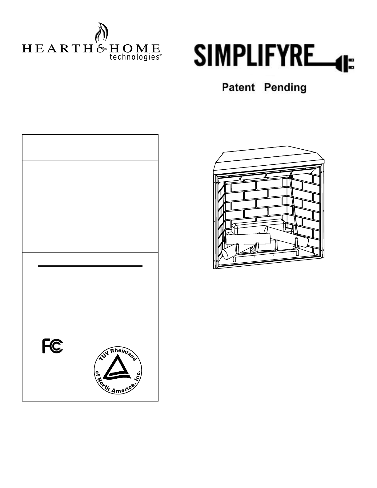
Model: SFE-35
INSTALLER/CONSUMER SAFETY
INFORMATION
PLEASE READ THIS MANUAL BEFORE
INSTALLING AND USING APPLIANCE.
WARNING!
IF THE INFORMATION IN THIS
MANUAL IS NOT FOLLOWED
EXACTLY, AN ELECTRICAL SHOCK
OR FIRE MAY RESULT, CAUSING
PROPERTY DAMAGE, PERSONAL
INJURY OR LOSS OF LIFE.
TM
BUILDER BOX
FOR YOUR SAFETY
SERVICE MUST BE PERFORMED BY
A QUALIFIED SERVICE AGENCY.
DO NOT STORE OR USE GASOLINE
OR OTHER FLAMMABLE VAPORS
AND LIQUIDS IN THE VICINITY OF
THIS OR ANY OTHER APPLIANCE.
C
ANSI / UL 2021. Fixed or location dedicated electric room heater.
Installer: do not discard this manual -- leave for home owner
US
TUV Listed as SFE-35
Homeowner’s Installation & Operating Manual
Note: The device complies with Part 15 of the FCC Rules.
Operation is subject to the following two conditions:
1. This device may not cause harmful interference, and
2. This device must accept any interference received, including
interference that may cause undesired operation.
1 Hearth & Home Technologies Inc. • SFE-35 • 4050-313 Rev C • 01/08
Page 2

Congratulations!
Congratulations on selecting a Simplifyre electric fi replace.
The unit you have selected is designed to provide the utmost
in safety, reliability and effi ciency.
As the owner of a new fi replace, you’ll want to read and
carefully follow all of the instructions contained in this
owner’s manual. Pay special attention to all cautions and
warnings.
This owner’s manual should be retained for future reference.
We suggest you keep it with your other important documents
and product manuals.
TABLE OF CONTENTS
Please read the installation & operation instructions before
using this appliance.
1 Important Instructions 3
A Unpacking the Unit . . . . . . . . . . . . . . . . . . . . . . . . . . . 4
B. Locating Your Electric Fireplace . . . . . . . . . . . . . . . . . 4
C. Clearance to Combustibles . . . . . . . . . . . . . . . . . . . . . 4
D. Framing . . . . . . . . . . . . . . . . . . . . . . . . . . . . . . . . . . . . 4
E. Electrical Specifi cations . . . . . . . . . . . . . . . . . . . . . . . . 4
F. Hardwire Electrical Connections . . . . . . . . . . . . . . . . . 4
G. Wall Switch and Thermostat Connections . . . . . . . . . . 4
H. Finishing . . . . . . . . . . . . . . . . . . . . . . . . . . . . . . . . . . .4
2 Fireplace Dimensions 5
3 Operating Instructions 6
A. Remote Control . . . . . . . . . . . . . . . . . . . . . . . . . . . . . .6
B. Remote Control Initialization . . . . . . . . . . . . . . . . . . . . 6
C. Control Usage . . . . . . . . . . . . . . . . . . . . . . . . . . . . . . . 6
4 Electrical Wiring 7
5 Service Instructions 7
A. Replacing the Light Bulb . . . . . . . . . . . . . . . . . . . . . . . 7
B. Screen Cleaning . . . . . . . . . . . . . . . . . . . . . . . . . . . . . 7
C. Maintenance of Motors . . . . . . . . . . . . . . . . . . . . . . . . 7
D. Resetting the Temperature Cutout Switch . . . . . . . . . . 7
6 Replacement Parts List 8
7 Warranty 9
The information contained in this owner’s manual unless
noted otherwise, applies to all models.
Your new Simplifyre electric fi replace will give you years of
durable use and trouble-free enjoyment.
Welcome to the Hearth & Home Technologies family of
fi replace products!
2 Hearth & Home Technologies Inc. • SFE-35 • 4050-313 Rev C • 01/08
Page 3

Important Instructions
1
WARNING! Risk of Fire!
DO NOT:
• install or operate damaged heater
• modify heater
• operate the heater without fully assembling all
components
The following actions are strictly prohited:
• Installation other than as instructed by Hearth & Home
Technologies Inc.
• Installation and/or use of any component part not
approved by Hearth & Home Technologies Inc.
Hearth & Home Technologies Inc. disclaims any responsibility
for, and the warranty and agency listing will be voided by the
above actions.
When using electrical heaters, basic precautions should always be followed to reduce the risk of fi re, electric shock and
injury to persons, including the following:
• Read all instructions before using this heater.
• This heater is hot when in use. To avoid burns do not let
bare skin touch hot surfaces. If provided, use handles
when moving this heater. Keep combustible materials,
such as furniture, pillows, bedding, papers, clothes and
curtains away from sides and rear of heater, and at least
36 in. (914 mm) from the front.
• Extreme caution is necessary when any heater is used
by or near children or invalids and whenever the heater
is left operating and unattended.
• Always unplug heater when not in use.
• Do not operate any heater with a damaged cord or plug
or after the heater malfunctions, has been dropped or
damaged in any manner. Return heater to authorized
service facility for examination, electrical or mechanical
adjustment, or repair.
• Do not use outdoors.
• This heater is intended for use in bathrooms, laundry
areas and similar indoor locations. Never locate heater
where it may fall into a bathtub or other water container.
• Do not run cord under carpeting. Do not cover cord with
throw rugs, runners, or the like. Arrange cord away from
traffi c areas and where it will not be tripped over. Do not
coil cord.
• To disconnect heater, turn controls to “OFF” then remove
plug from outlet.
• Do not insert or allow foreign objects to enter any
ventilation or exhaust opening as this may cause an
electric shock or fi re, or damage the heater.
WARNING! Improper installation, adjustment, alteration, service or maintenance can cause injury or property damage. Refer to the owner’s information manual
provided with this heater. For assistance or additional
information consult a qualifi ed installer, service agency or
your dealer.
NOTICE! This fi replace is not intended for use as a primary
heat source and should not be factored as such in residential
heating calculations.
WARNING! Risk of Electric Shock! This product should
never be installed near water.
• To prevent a possible fi re, do not block air intakes or
exhaust in any manner.
• A heater has hot and arcing or sparking parts inside. Do
not use it in areas where gasoline, paint, or fl ammable
liquids are used or stored.
• Use this heater only as described in this manual. Any
other use not recommended by the manufacturer may
cause fi re, electric shock, or injury to persons.
• Always use properly grounded, fused and polarized
outlets.
• Always use ground fault protection where required by
electrical code.
• Always disconnect power before performing any cleaning,
maintenance or relocation of the heater.
• To prevent a possible fi re, do not burn wood or other
materials in this heater.
• To prevent electric shock or fi re, always use a certifi ed
electrician should new circuits or outlets be required.
• When transporting or storing the heater, keep in a dry
place free from excessive vibration and store to avoid
damage.
• Avoid the use of an extension cord because the extension
cord may over heat and cause a risk of fi re. However,
if you have to use an extension cord, the cord shall be
No. 16 AWG minimum size and rated not less than 1875
watts.
• SAVE THESE INSTRUCTIONS FOR FUTURE
REFERENCE.
3 Hearth & Home Technologies Inc. • SFE-35 • 4050-313 Rev C • 01/08
Page 4

A Unpacking the Unit
WARNING! Do NOT use this appliance if any part has
been under water. Immediately call a qualifi ed service
technician to inspect and to replace any part of the electrical system if necessary.
F. Hardwire Electrical Connections
WARNING! Electrical wiring must comply with local
building codes and other applicable regulations to
reduce the risk of fi re, electrical shock and injury.
Carefully remove packaging from the unit. The front screen
is held in place with four Phillips head screws. To remove
the screen, extract the screws. Grasp the screen frame and
pull out.
B. Locating Your Electric Fireplace
Your new electric fi replace may be installed virtually
anywhere in your home. However, when choosing a location
ensure that the general instructions are followed. For best
results, install out of direct sunlight.
Power supply service must be either completed or placed
within the heater prior to fi nishing to avoid reconstruction.
Protective cover may stay on during framing, but must be
removed before fi nal fi nishing. Once fi nal fi nishing has been
completed, the protective cover can be used to protect the
heater until fi nal installation is complete.
C. Clearance to Combustibles
Sides . . . . . . . . . . . . . . . . . . . . . . . . . . .0 in. (0 mm)
Floor . . . . . . . . . . . . . . . . . . . . . . . . . . . . 0 in. (0 mm)
Top . . . . . . . . . . . . . . . . . . . . . . . . . . . . .0 in. (0 mm)
Back . . . . . . . . . . . . . . . . . . . . . . . . . . . . 0 in. (0 mm)
D. Framing
• Choose a fireplace location and frame as shown in
Figure 2.1.
• Frame in the fi replace with a header across the top.
• It is important to allow for fi nished face when setting the
depth of the frame.
• If a hearth system or raised hearth is to be installed, the
unit MUST be raised to provide service access and use
of optional fronts.
• The fi replace can now be positioned in the opening.
• Level it with shims if necessary, and attach the unit to the
frame using the nailing fl anges provided.
Note: All wiring must be completed prior to fi nishing the
unit.
For supply connections use No. 14 AWG or larger wires. Use
copper wire only. Connect only to a 15 AMP branch circuit.
A dedicated circuit is recommended as other appliances on
the circuit may cause the breaker to trip or fuse to blow
when the heater is operating.
• Remove the screws securing the junction block cover.
• Wire to a properly grounded, 120 volt, 60 Hz, 15 AMP
circuit
• Ensure all junction block connections are tight.
• Replace the cover and retaining screws.
• Plug in the IEC-320-C14 power plug to the IEC-320-C13
power inlet located on the upper right side of the unit.
• All components and wiring may be inspected by removing
the top inter-panel through the fi replace front opening.
G. Wall Switch and Thermostat Connections
WARNING! Do NOT connect the optional low voltage
switch and/or thermostat to 120 volt branch circuit.
The Optional Wall Switch 4050-309 contains two single pole
switches. (LEVITON 5634 Series or equal)
The Optional Wall Thermostat is a low voltage mechanical
type. (Columbus Electric RK120EAA or equal)
Maximum run distance is 30 ft. (9.14 m) with 20 gauge
solid copper low voltage thermostat wire. Connect per the
electrical wiring diagram on page 7.
H. Finishing
Combustible or non-combustible materials may be used to
fi nish up to the fi replace opening.
Note: ensure that you leave adequate room to remove and
replace the front screen or optional front.
E. Electrical Specifi cations
Voltage . . . . . . . . . . . . . . . . . . . . . . 120 V AC, 60 Hz
Total Amps . . . . . . . . . . . . . . . . . . . . . . . . . .9.6 AMP
Total Watts . . . . . . . . . . . . . . . . . . . . . . . 1050 Watts
Heater Rating . . . . . . . . . . . . . 1000 Watts/3415 BTU
4 Hearth & Home Technologies Inc. • SFE-35 • 4050-313 Rev C • 01/08
Page 5

Fireplace Dimensions
2
22 in.
55.9 cm
12.5 in.
31.8 cm
Unit Top
35 in.
88.9 cm
Unit Front
33.75 in.
85.7 cm
1/2 in. (13 mm)
L
48 in.
121.9 cm
85.4 cm
30.5 in.
77.5 cm
12.75 in.
32.4 cm
Rough
Opening
33.6 in.
Depth
Note: Nailing flanges may be
hand-bent to accommodate framing
for different styles of optional
decorative fronts. Refer to decorative front installation manuals for
details. If the fireplace will be inset,
add .5 in. (13 mm) to the framing
depth.
36.5 in.
92.7 cm
Rough Opening Width
Flush
Nailing Flange
34 in.
86.4 cm
Rough
Opening
Height
Figure 2.1 Fireplace Specifi cations and Framing Dimensions
Note: The bottom surface of this
fireplace must be elevated to the
level of the finished surface in
front of the fireplace to allow
access for service and the use
of optional fronts.
5 Hearth & Home Technologies Inc. • SFE-35 • 4050-313 Rev C • 01/08
Page 6

OPERATING INSTRUCTIONS
3
Ensure the appliance is connected to a properly grounded electrical outlet on a minimum 15 AMP circuit. If a new outlet is
required, it should be installed by a qualifi ed electrician according to applicable building codes.
A. Remote Control
Note: If the fi replace does not respond to the hand held control see “Remote Control Initialization” below.
This equipment has been tested and found to comply with the limits for class B digital device, pursuant to Part 15 of the FCC
Rules. These limits are designed to provide reasonable protection against harmful interference in residential installation. This
equipment generates and uses, and can radiate radio frequency energy and, if not installed and used in accordance with
the instructions, may cause harmful interference to radio communications. However, there is no guarantee that interference
will not occur in a particular installation. If this equipment does cause harmful interference to radio or television reception,
which can be determined by turning the equipment off and on, the user is encouraged to try to correct the interference by
one or more of the following measures:
• Re-orient or relocate the receiving antenna.
• Increase the separation between the equipment and receiver.
• Connect the equipment into an outlet on a circuit different from that to which the receiver is connected.
• Consult the dealer or an experienced radio/TV technician for help.
B. Remote Control Initialization
This procedure is required only when the unit is installed or
the transmitter is replaced and is not affected by the loss of
power.
• Ensure that power is supplied through main service
panel.
• Place fresh batteries in the transmitter.
• Access the LEARN button by removing the front
screen.
• Press and hold down the learn button. You will hear a
beep.
• Press a button on the hand-held transmitter.
• Release the learn button when you hear the long beep.
Learn Button
• This completes the remote control receiver/transmitter
initialization.
C. Control Usage
The controls operate the fi replace modes.
• The fl ame effect and backlog/embers are turned ON/OFF
by alternate action of the FLAME button on the remote
transmitter.
• The heater/blower and front embers are turned ON/OFF
FLAMES
HEATER
6 Hearth & Home Technologies Inc. • SFE-35 • 4050-313 Rev C • 01/08
by alternate action of the HEATER button on the remote
transmitter.
• The optional wall FLAME switch provides manual
operation (ON/OFF) of the fl ame effect.
• The optional wall HEAT switch controls the front embers
and activates the optional remote wall thermostat.
• Set the thermostat to the desired room temperature.
The optional wall switches/thermostat are in parallel with
the remote control relays. The wall switches MUST be OFF
for the Remote Transmitter to control the fi replace.
Note: While the heater is ON the embers in front will glow.
Ensure the heater is OFF when unattended.
Page 7

Electrical Wiring
4
Projector
X1
Lamp
S7
M
Motor
Interlock on
Media Cabinet only
P1
Remote Receiver
Flame
Hot Line
Ground
Neutral
Branch Circuit
NEMA-5
Heater-Blower
IEC 320 C13/C14
Power Supply Module
12 VOC
Power
Supply
Hi Limit
Heater
M
Motor
Heat
RD
Flame
Terminal Strip
J1
Ember Bed & Back Log
R2
LED LED LED
D1
R1
LED LED LED
Heat Indicator
ON
1
Heat
WH
WH
RD
5
4050-310
Wall Thermostat
4050-309
Wall Switch
Service Instructions
5
WARNING! Disconnect power at circuit breaker before
attempting any maintenance or cleaning to reduce the
risk of fi re, electrical shock or personal injury.
A. Replacing the Light Bulb
This appliance uses a single 12 Volt, 35 Watt, MR-16 bulb.
The bulb is located behind the smoke shield.
A spare is provided with the unit. Replacement bulbs
(Part No. 4050-123) are available through your Simplifyre
dealer.
• Turn off power to the unit at the main service panel.
• Let the fi replace cool if it has been operating.
• Release the spring pins and remove the upper shield.
• Remove the two screws on the projector basket.
• Rotate the housing down to access the bulb.
• Remove the screws holding the bulb and socket.
• Unplug the bulb from the socket.
• Replace the bulb.
• Re-assemble in the reverse order.
B. Screen Cleaning
During shipment, installation, handling, etc., the screen
surface may collect dust particles; these can be removed
by lightly wiping with a clean, dry cloth.
C. Maintenance of Motors
The motors used on the fan and fl ame projector assembly
are pre-lubricated for extended bearing life and require no
further lubrication. However, periodic cleaning/vacuuming
of the fan/heater unit is recommended.
D. Resetting the Temperature Cutout Switch
The heater on this fi replace is protected with a safety device
to prevent overheating. Should the heater overheat, an
automatic cutout will turn OFF the heater/blower. The switch
is reset by turning the unit OFF, waiting 10-15 minutes and
switching the unit back ON.
7 Hearth & Home Technologies Inc. • SFE-35 • 4050-313 Rev C • 01/08
Page 8

E. Optional Wall Switch / Thermostat Wiring
Connections instructions
The optional wall switch and thermostat wiring is low voltage
and must be separated from power wiring. Do not connect
the switches or thermostat to house power.
To control the fi replace with a single switch:
(fl ames/ember bed and heater/front embers all on or all off)
• Switch between terminal 1 and 2
• Jumper wire between terminal 2 and 3
• Jumper wire between terminal 4 and 5
To control fl ames/ember bed with one switch and
heater/front embers with another switch:
• Switch 1 - turns fl ames/ember bed ON/OFF
• Switch 2 - turns heater/front embers ON/OFF
• Switch 1 between terminal 1 and 2
• Switch 2 between terminal 1 and 3
• Jumper wire between terminal 4 and 5
To control fl ames/ember bed with a switch, and
control the heater with a thermostat:
• Switch 1 - turns fl ames/ember bed ON/OFF
• Switch 2 - turns front embers ON/OFF indicating the
heater/fan is being controlled by the thermostat (UL
requirement)
• Thermostat turns heater/fan ON/OFF as room temperature
requires it
• Switch 1 between terminal 1 and 2
• Switch 2 between terminal 1 and 3
• Thermostat between terminal 4 and 5
8 Hearth & Home Technologies Inc. • SFE-35 • 4050-313 Rev C • 01/08
Page 9

Service Parts
SFE-35 & SFE-35C
35” Electric Fireplace
Simplifyre
4
10
7
8
6
5
16
12
11
9
Beginning Manufacturing Date: Dec 2006
Ending Manufacturing Date: Active
1
13
14
15
2
3
IMPORTANT: THIS IS DATED INFORMATION. When requesting service or replacement
parts for your appliance please provide model number and serial number. All parts listed
in this manual may be ordered from an authorized dealer.
Stocked
at Depot
ITEM DESCRIPTION COMMENTS PART NUMBER
1 Viewing Screen
2 Back Log
3 Front Log Set/ Ember Bed Assembly
4 Smoke Shield
5 Grate
6 Projector Assembly
7 Front Screen Assembly
8 Bulb
4050-144
4050-177
4050-178
4050-176
4050-141
4050-002
4050-008
4050-123
9 Remote Transmitter 4050-105
10 120V Heater Assembly
11 Power Assembly
4050-104
4050-001
12 Remote Receiver 4050-108
13 LED Assembly
4050-013
14 Optional lWall Switch ***
15 Optional Wall Thermostat
16
Installation Manual (SFE-35)
Installation Manual (SFE-35C)
****
4050-313
4050-314
***To be supplied by the customer (Leviton 5634 series ) Refer to page 4 fo Installation manual
*****To be supplied by the customer (Columbus Electric RK120EAA or equal ) Refer to page 4 fo Installation manual
Additional service parts on following page.
Y
Y
Y
Y
Y
Y
Y
Y
Y
Y
Y
Y
Y
02/12
Page 10

Service Parts
IMPORTANT: THIS IS DATED INFORMATION. When requesting service or replacement
parts for your appliance please provide model number and serial number. All parts listed
in this manual may be ordered from an authorized dealer.
ITEM DESCRIPTION COMMENTS PART NUMBER
Back Refractory 4050-175
Hardwire Power Cord (SFE-35 only)
Left Rear Refractory 4050-174
Left Refractory 4050-172
Power Cord
Right Rear Refractory 4050-173
Right Refractory
Screw, 10-24 x Phillips Pkg of 24 419-802/24
Sheet Rock Ledge 4050-211
Top Pan
SFE-35 & SFE-35C
Beginning Manufacturing Date: Dec 2006
Ending Manufacturing Date: Active
4050-005
4050-148
4050-171
4050-050
Stocked
at Depot
Y
Y
Y
Y
Y
Y
Y
Y
Y
Y
02/12
Page 11

Warranty
7
TM
Warranty
Hearth & Home Technologies Inc. (HHT) Electric Fireplaces are tested and inspected prior to shipment and are
guaranteed from defect to the purchaser of each new product. Any part which proves to be defective in material or
workmanship under normal use within one year will be repaired or replaced without charge.* The Company will not
be responsible for any expense incurred for installation, removal from service, or transportation costs. Any such
defect should be brought to the attention of the Dealer where the product was purchased and is authorized to repair
or replace within the terms of this warranty.
The Company’s only obligation under this warranty will be at its sole option to repair or replace any part proving
defective or to refund the purchase price thereof.
The owner/user assumes all other risks, if any, including the risk of any direct, indirect or consequential loss or damage
arising out of the use of or inability to use the product.
The warranty will not apply if, in the sole judgement of the Company, damage or failure has resulted from accident,
alteration, misuse, abuse, incorrect installation, or operation on an incorrect power source.
The foregoing is in lieu of all other warranties expressed, implied, or statutory, and the Company neither assumes, nor
authorizes any person to assume for it any other obligation, or liability in connection with said product.
*Light bulbs are not covered in the warranty.
How to Obtain Service.
To obtain service under this warranty you must:
1. Send written notice of the claimed condition to Heatilator Technical Service Department, Hearth & Home Technologies
Inc., 1915 W. Saunders St., Mt. Pleasant, IA 52641.
2. Provide proof of purchase, model number, serial number, and manufacturing date code to HHT.
3. Provide HHT reasonable opportunity to investigate the claim, including reasonable opportunity to inspect the
appliance prior to any repair or replacement work and before the Appliance or any component of the Appliance has
been removed from the place of original installation.
4. Obtain HHT’s consent to any warranty work before the work is done.
ADDITIONAL INFORMATION. If you would like information on current HHT products or want to locate a dealer in
your area, call 1-800-927-6841
©2003 Heatilator® is a Registered Trademark of Hearth & Home Technologies Inc
10 Hearth & Home Technologies Inc. • SFE-35 • 4050-313 Rev C • 01/08
 Loading...