

Page 1
TM
Installation
TM
Instructions
Models:
GFK21B
Fan Kit
If you need clarifi cation of any of the instructions contained here contact your dealer or the Technical Services Department
at 1-800-927-6841.
The Fan Kit has been designed to circulate room air through the appliance to enhance heat output. The fan kit operates on
120VAC, 60 Hz power. This is available through a receptacle in the factory installed junction box. The junction box is located
in the controls compartment of the appliance.
A control module is provided with the fan kit which automatically turns the fan on and off at preset times and is equipped
with a variable speed control to provide a quiet forced air fl ow at the desired speeds.
Check Contents of Shipping Carton
Compare contents of carton in Table 1 with the actual parts received. If any parts are missing or damaged, contact your
dealer before starting installation. Do not install a damaged fan kit.
Installation Precautions
The Fan Kit is tested and safe when installed in accordance with this installation manual. It is your responsibility to read
all instructions before starting installation and to follow these instructions carefully during installation to assure maximum
benefi t from, and safe operation of the fan.
WARNING
Shock Risk
Explosion Risk
Do NOT wire 110-120 VAC to gas control
valve.
Do NOT wire 110120 VAC to wall switch
• Incorrect wiring will damage millivolt
values.
• Incorrect wiring will override IPI safety
lockout and may cause explosion.
Note: This appliance must be electrically wired and grounded
in accordance with local codes or, in the absence of local
codes, with National El ect r i c Cod e A N S I / N FPA 70 - latest
edition or the Canadian Electric Code CSA C22.1.
CAUTION
Sharp Edges
• Wear protective gloves and safety
glasses during installation.
WARNING
Shock Risk
Fire Risk
Use ONLY optional accessories approved
for this appliance.
• Using non-listed accessories voids
warranty.
• Using non-listed accessories may result
in a safety hazard.
• Only Hearth & Home Technologies
approved accessories may be used
safely.
Fan 1
Screws 6
Foam Tape 2
Control Module 1
Electrical Cord 1
Magnetic Tape 2
Fan Bracket 1
Jumper Wire (blue) 1
Table 1 Contents of Carton
Note: An arrow (¨) found in the text signifi es change in
content.
Hearth & Home Technologies • GFK21B Fan Kit • 4016-096 Rev H • 05/08
Note: You may not need all parts included with this kit.
1
Page 2
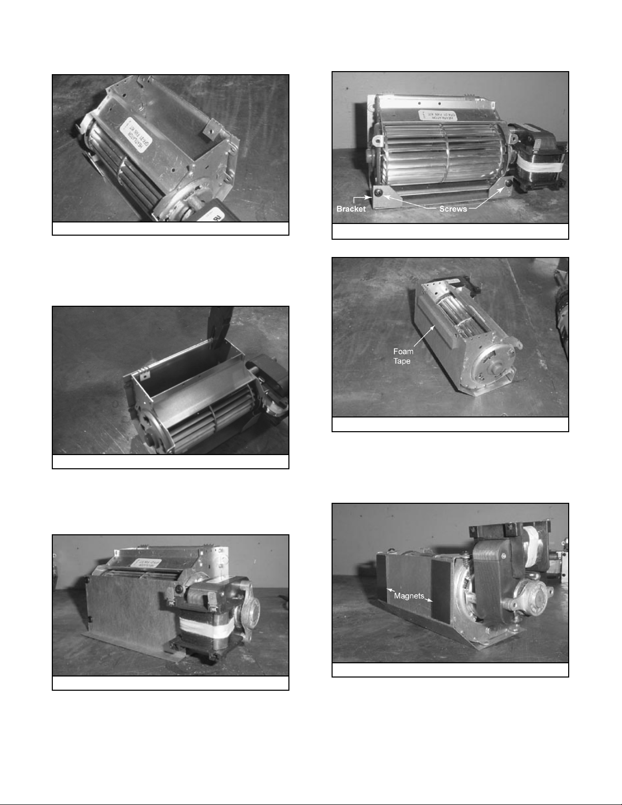
1. Install the Fan Bracket & Shield
• Place the fan bracket around the fan. See Figure 1.
• If no fan shield is needed, install screws to hold the front
of the fan bracket in place. See Figure 4.
Figure 1 Fan Bracket-No screws
• Use pliers to crimp the bracket tabs around the fan
¨
housing. See Figure 2.
¨
Figure 2 Crimp Bracket Tabs
• If the fan is being installed in a B-vent appliance, the fan
shield supplied with the appliance will also need to be
attached. See Figure 3.
Figure 4 Fan Bracket
Figure 5 Foam Tape
• Attach the foam tape (Figure 5) and magnets (Figure 6)
to the fan. Cut one magnet strip in half and save the
remaining strip for control module.
Figure 3 Fan Shield
2
Figure 6 Magnets
Hearth & Home Technologies • GFK21B Fan Kit • 4016-096 Rev H • 05/08
Page 3

2. Remove Valve Assembly
On a Novus 30 in. appliance (GNDC30 or GNBC30 only) the
valve assembly must be raised slightly to allow the fan to be
moved past it to the back of the appliance.
FIREBOX
BOTTOM
3. Install the Fan
Position the fan all the way to the rear and center in the appliance. Press the fan (magnets to the bottom) to the back of
the appliance. See Figure 7. Plug the fan cord into the fan
receptacle labeled “FAN” on the junction box. See Figure 8.
4. Install the Control Module
Attach the control module to the bottom pan using the magnetic tape provided.
5. Wiring the Fan Control Module
Note: Fan control timer only for use on units with junction
box pictured in Figure 9.
• Robertshaw Valve (Standing Pilot)
- Connect the black, white and red wires with 1/4 in.
female connectors from the fan control module to the
appliance junction box as shown in Figure 9.
- Connect the black ground wire with the ring terminal
to the TP screw on the valve (center).
- Remove wall switch wire connected to valve terminal
marked “TH”.
- Connect the black with white stripe wire with 3/16 in.
piggyback connector from fan control module to valve
terminal marked “TH”.
- Connect wall switch wire removed from valve terminal
“TH” to the piggyback connector on the black with white
stripe fan control module wire.
FAN
BOTTOM PAN
Figure 7 Rotate Fan
Fan Assembly
Junction Box
Figure 8 Position the Fan
APPLIANCE
BACK
Cord
Clips
Note: Thermopile must be wired as shown in Figure 9.
Thermopile
RS
Val ve
Black Ground
Figure 9 Robertshaw Wiring Diagram
TH
TP
TP
TH
Black/White
White
Red
Fan
Control
Module
Wall
Switch
White
Red
Black
Hearth & Home Technologies • GFK21B Fan Kit • 4016-096 Rev H • 05/08
3
Page 4

• Dexen Valve (IPI)
- Connect the black, white and red wires with 1/4 in. female connectors from fan control module to appliance junction
box as shown in Figure 10.
- Connect the black ground wire to the appliance.
- Remove the green ignition control wire from the valve.
- Connect the black with white stripe wire with 3/16 in. piggyback connector from fan control module to valve.
- Connect green ignition control wire to piggyback connector on black with white stripe fan control module wire.
Dexen
Val ve
Green Wire from Ignition Control
White
Black/White
Black
Ground
Figure 10 - Dexen (IPI) Wiring Diagram
Fan
Control
Module
Red
Black
• SIT Valve
- Connect the black, white and red wires with 1/4 in. female connectors from fan control module to appliance junction
box as shown in Figure 11.
- Connect the black ground wire with the ring terminal to the TP screw on the valve (center).
- Connect blue jumper wire between fan control wire (black with white stripe) and valve. Plug 1/4 in. female end of blue
jumper wire to the back side of valve wiring block marked TH.
White
Red
Black
Wall
Switch
SIT
Val ve
Ground
Figure 11 - SIT Wiring Diagram
TH
TP
TP
TH
Black/White
Black
Red
White
Fan
Control
Module
Thermopile
Blue
6. Recommended Fan Control Set-up Procedure
Note: The test sequence works only during the fi rst (approximately) seven minutes after power-up.
• With burner and pilot extinguished:
• Turn control knob clockwise to activate control.
• Press and hold test button on the control module.
- Fan will turn on.
- Adjust fan speed with control knob.
- Release test button. Fan will stop.
• Light burner.
4
Hearth & Home Technologies • GFK21B Fan Kit • 4016-096 Rev H • 05/08
• Press and release test button.
- Fan will come on at set speed
- After one minute fan will stop.
• Extinguish burner.
• Fan control is now fully operational and will operate
automatically each time appliance is used.
• Operates with APPROXIMATELY a 7-minute delay to turn
on and a 12-minute delay to turn off.
 Loading...