

Page 1

user guide
Page 2

Page 3
ADVANTAGES / FEATURES
• Virtually unlimited system size
HEAR BACK SYSTEM DESCRIPTION
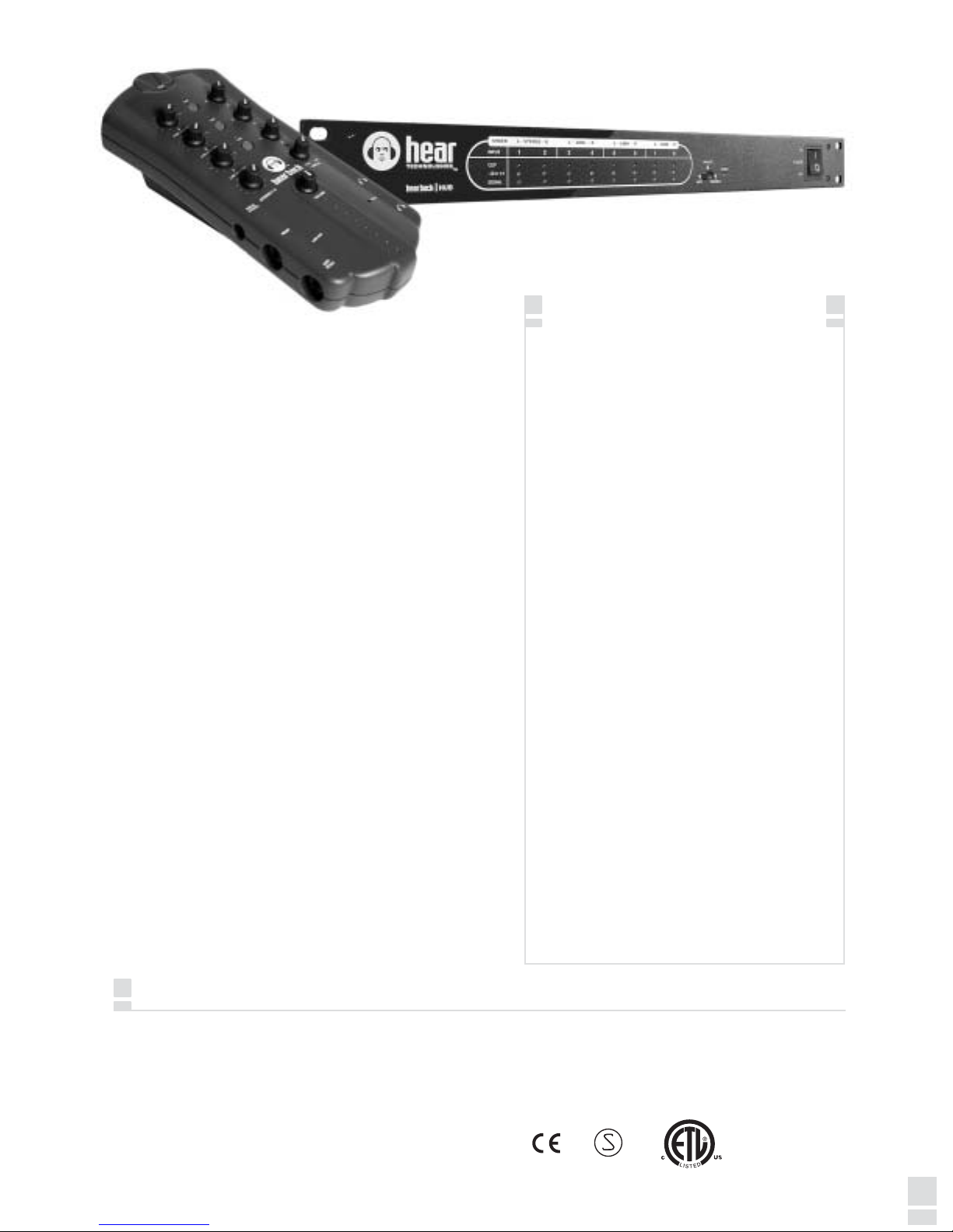
The basic Hear Back™ system consists of a hub
and personal mixers. The hub receives any of
the three input signals and converts them to
HearBus digital audio plus power. The mixers
are connected to the hub using CAT5E cable.
A single hub supplies digital audio and power to
a maximum of eight mixers. That's one for you
and everybody in the band! If that's not enough,
the hubs can be daisy-chained using the
HearBus In and HearBus Out for virtually
unlimited system size.
The hub may be connected to recording
equipment, digital audio workstations, and
analog or digital consoles.
The mixer is placed near the talent and gives
them control over the audio inputs. The user-
friendly system saves system setup time.
• Excellent quality and audio fidelity
• High power - low distortion
headphone amplifiers
• Very long interconnect without loss
of audio quality
• Three audio inputs: ADAT® optical,
analog, and HearBus are switch
selectable from the front panel
• Local control of up to ten channels
of audio - 8 inputs plus a stereo Aux
input
• Built-In DSP limiter for hearing and
monitoring device protection
• Headphone amplifier fault LED
• Bus status indicator
• Link indicators/switches - links mono
pairs for stereo operation
• Standard CAT5E cable for power
and signal connection to mixers
• Built-in cable strain relief
• Balanced line outputs - mono/stereo
• Stereo AUX in
FCC Statement
Note: This equipment has been tested and found to comply with the limits for a Class B digital device, pursuant to part 15 of the FCC Rules. These limits are
designed to provide reasonable protection against harmful interference in a residential installation. This equipment generates, uses and can radiate radio
frequency energy and, if not installed and used in accordance with the instructions, may cause harmful interference to radio communications. However, there is
no guarantee that interference will not occur in a particular installation. If this equipment does cause harmful interference to radio or television reception, which
can be determined by turning the equipment off and on, the user is encouraged to try to correct the interference by one or more of the following measures:
• Reorient or relocate the receiving antenna.
• Increase the separation between the equipment and receiver.
• Connect the equipment into an outlet on a circuit different from that
to which the receiver is connected.
• Consult the dealer or an experienced radio/TV technician for help.
• Built-In mic stand mount as well as
desktop mount capability
0318
Page 4

Page 5
MIXER FEATURES
• Local control of up to ten channels of audio
• Master volume
• Built-in DSP limiter
• 24-bit D/A converters
• Less than 1.5 millisecond total system delay
• Bus status indicator
• Headphone amplifier fault indicator
• Link indicators
• Standard CAT5E power and signal connection
• Balanced, mono/stereo, line outputs
• +4 dBu level TRS unbalanced stereo AUX in:
- Expand numbers of mixes
- Drum module/metronome or local mix input
MIXER CONSTRUCTION
The Hear Back mixer is constructed of UV-stabilized ABS
and has a built-in mic stand mount. Two cable strain reliefs
greatly reduce stress on the CAT5E cable connectors and the
mixer RJ45 connector.
STATUS INDICATORS
The mixer has three types of status indicators:
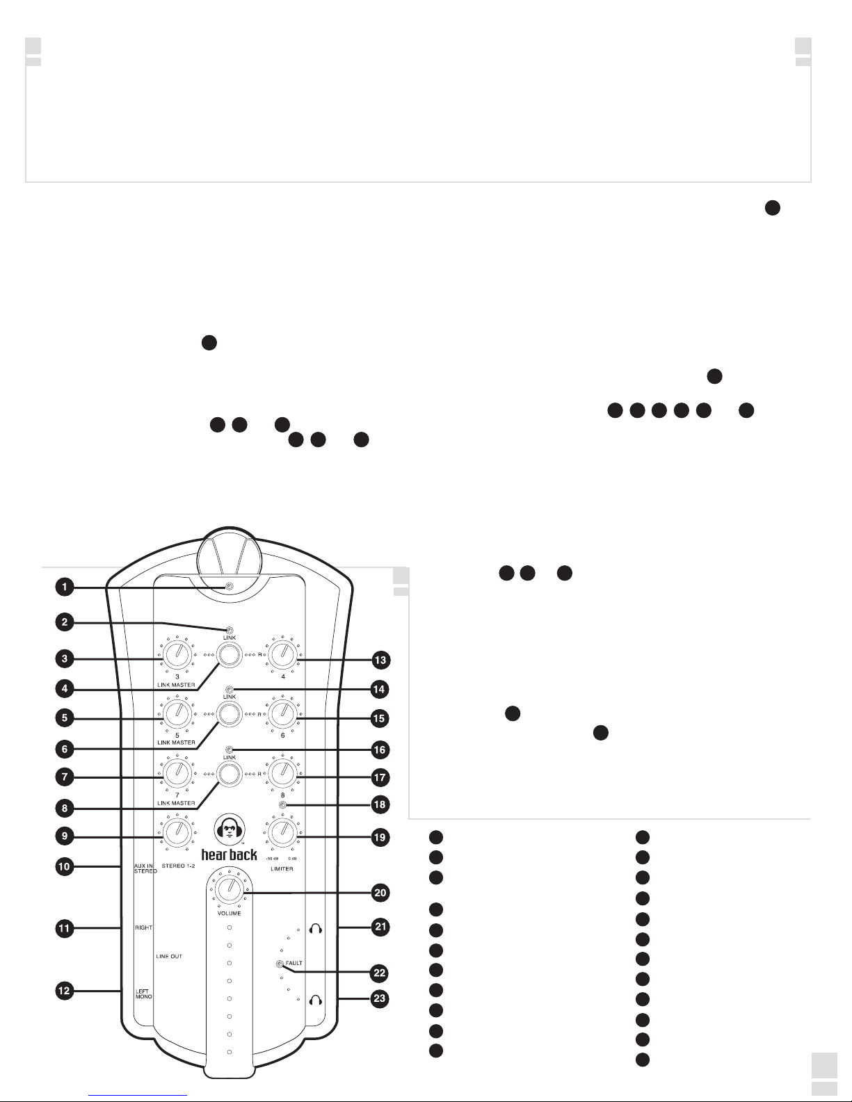
1. BUS - The bus indicator (1) is a bi-color LED that is green
1
under normal operating conditions, indicating the
HearBus clock is present. In the absence of the clock, the
indicator turns red alerting the user a problem exists at
the hub or connection to the hub.
2. LINK - The link indicators (2),
whenever the associated link switch(es) (4), (6) and (8)
(14) and (16) illuminate
2
14 16
4 6 8
are pressed. Switch settings are stored in non-volatile
flash memory whenever power is removed.
3. HEADPHONE AMPLIFIER FAULT - The fault indicator
(22) is
22
normal off and only illuminates red if an over-current or short
circuit condition occurs. The circuit shuts down the
headphone amplifier and upon cooling returns to normal
operation. Continued cycling of the fault circuit is not
recommended as excessive cycling can degrade the
amplifier's performance and life.
LINK OPERATION
Normally, a stereo mix is connected to the hub channels 1 and
2. These are typically the front of house or control room mix and
are controlled using the mixer stereo input knob (9).
9
The "more me" inputs are typically mono and are controlled
using the mono control knobs (3),
3 5 713 15 17
(13), (5), (15), (7) and (17). The
mono signals are center-panned in the stereo field when the link
indicator is off.
When a pair of mono inputs are linked, three things occur;
1. The left channel becomes the link master volume control for
the stereo pair.
2. The two inputs are hard panned left and right. Inputs can be
adjusted at the source to have a stereo spread anywhere
desired. Stereo signals are realized by using a pair of the
mono inputs: 2/4, 5/6, and/or 7/8 by simply pushing the link
switch
4 86
(4), (6), or (8).
3. The right mono volume now becomes inactive.
L
L
L
LIMITER
The limiter gives the user ultimate control of his/her hearing
protection as well as headphones, in-ear and conventional
loudspeaker monitoring devices in the event of excessive input
levels. The two-stage DSP limiter is an :1 or "brick wall"
8
limiter. The limiter is controlled using simple threshold
adjustment
The limiter active blue LED
19
(19).
18
(18) illuminates when the limiter is
active. If the indicator operates during normal program material
the dynamic range and quality of sound will suffer. NOTE:
Limiter should only be active when excessive signals are
present. To set the limiter, see Hear Back Connecting and
Calibration on page 6.
1
Bi-Color Bus Status Indicator
2
Link Indicator - Channels 3/4
3
Mono Channel 3/Stereo Link Master
Level
4
Link Switch - Links Channels 3/4
Mono Channel 5/Stereo Link Master
5
Link Switch - Links Channels 5/6
6
7
Mono Channel 7/Stereo Link Master
8
Link Switch - Links Channels 7/8
9
Stereo Mix Level Control, Channels 1/2
Stereo Auxiliary Input
10
Right Line Output
11
Left/Mono Line Output
12
Mono Channel 4
13
Link Indicator - Channels 5/6
14
Mono Channel 6
15
Link Indicator - Channels 7/8
16
Mono Channel 8
17
Limiter Indicator
18
Limiter Threshold Control
19
Master Volume
20
Headphone Output
21
Headphone Amplifier Fault Indicator
22
Headphone Output
23
0516
Page 6

Page 7
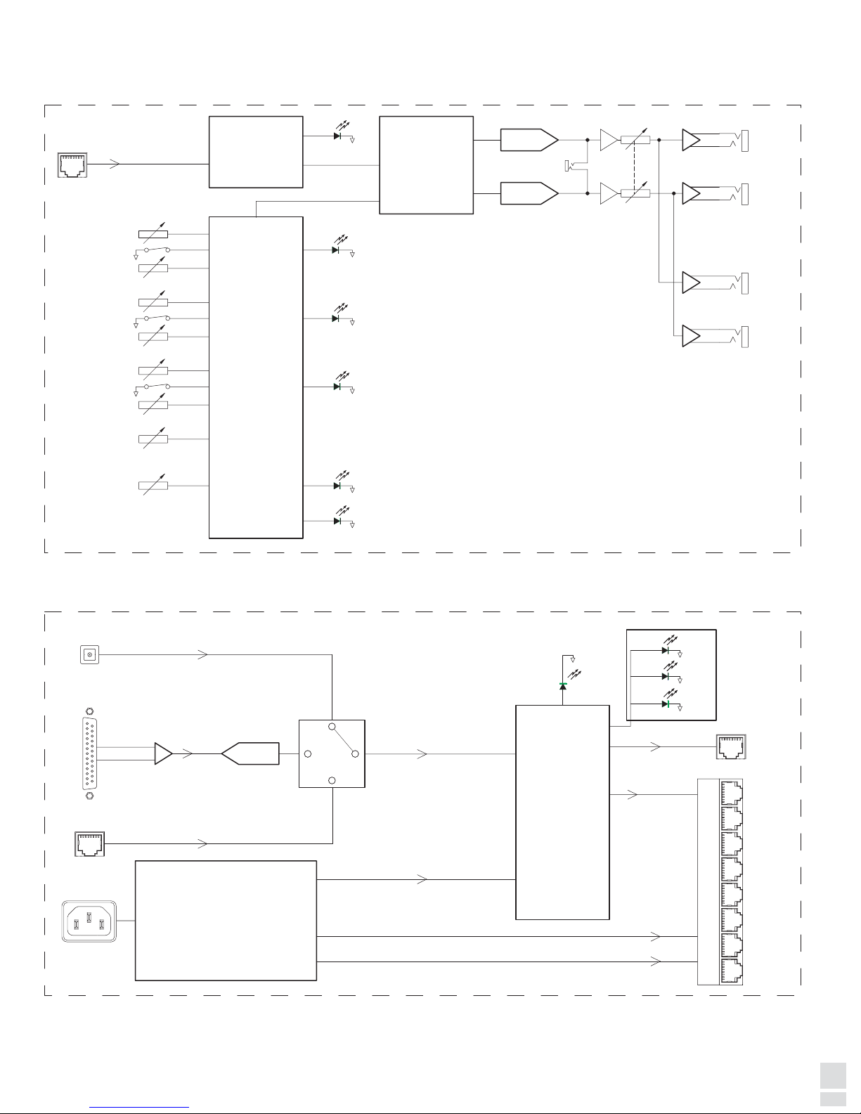
SYSTEM BLOCK DIAGRAM
uCONTROLLER
HearBus
MONO/LEFT
LINE OUT
24 BIT D/A
CONVERTER
RCVR
DSP
24 BIT D/A
CONVERTER
RIGHT LINE
OUT
MONO 3 - L
MONO 4 - R
LINK 3 - 4
LINK 5 - 6
MONO 6 - R
MONO 5 - L
LINK 7 - 8
MONO 8 - R
MONO 7 - L
LIMITER
THRESHOLD
LINK 3 - 4
LINK 5 - 6
LINK 7 - 8
LIMIT
STEREO
MASTER VOLUME
HP FAULT
BUS
HEADPHONE
OUT 2
HEADPHONE
OUT 1
STEREO
AUX IN
+ 16dB
CLIP
-32
-10 .. +4
ADAT OPTICAL
-18VDC
+18VDC
+5VDC
UNIVERSAL
POWER SUPPLY
24 BIT A/D
CONVERTER
HearBus
ANALOG
DIGITAL CIRCUITRY
INPUT
SELECT
CLOCK
EIGHT MIXER OUTPUTS
MIXER OUTPUTS
HearBus
Input Merering (x8)
SHORT CIRCUIT PROTECTION
HEAR BACK MIXER
HEAR BACK HUB
PATENT
PENDING
MIXER INPUT
AC POWER IN
ADAT IN
ANALOG INPUTS
HearBus IN
HearBus OUT
LINK MASTER/
LINK MASTER/
LINK MASTER/
0714
Page 8

Page 9

TROUBLESHOOTING AND OPERATING TIPS
No Signal Verify power is on.
Check input connections and input selector switch.
Verify the hub and mixers have green clock status indications.
Check output devices, headphones, wireless transmitter/receiver, monitor amplifiers, etc.
When I connect a line level
device to the mixer line
outputs, I hear a buzz.
Wire TRS outputs using only black (ring - ) and red (tip +) wires.
Disconnect shield at the mixer and terminate at receiving end only.
For unbalanced outputs wire the Black (ring - ) to the receiving end sleeve and tie the shield at the
receiving end only. Connect the tip (+ red) to the tip at the receiving end.
Setting the limiter
Set the limiter so it only activates in the presence of an excessive input signal. The limiter should only
be active in the event of excessive signals and should NOT be on when normal signals are present.
I have a clock signal at the
hub, but nothing at the mixer.
When I link two mono channels,
the stereo spread is incorrect.
The headphone amplifier fault
Isolate the problem as follows:
Check CAT5E cable or try another cable.
Try another mixer output port on the hub.
Try another mixer.
Verify the source (mixer, DAW, etc.) has these outputs panned hard left and right. The pan control of
the source determines the stereo spread.
The fault indicator indicates either a short circuit or excessive load.
indicator is on.
I need more mixes. Connect the stereo mix (channels 1&2) with the FOH or control room mix across several hubs (as
many as desired) then provide the "more me" sectional mixes to channel 3-8 on each hub until the
desired number of mix's are met. See "Large Stereo System" hook-up diagram, page 15.
The fan does not operate.
The fan only runs when power supply temperature reaches 60
o
C or 140o F.
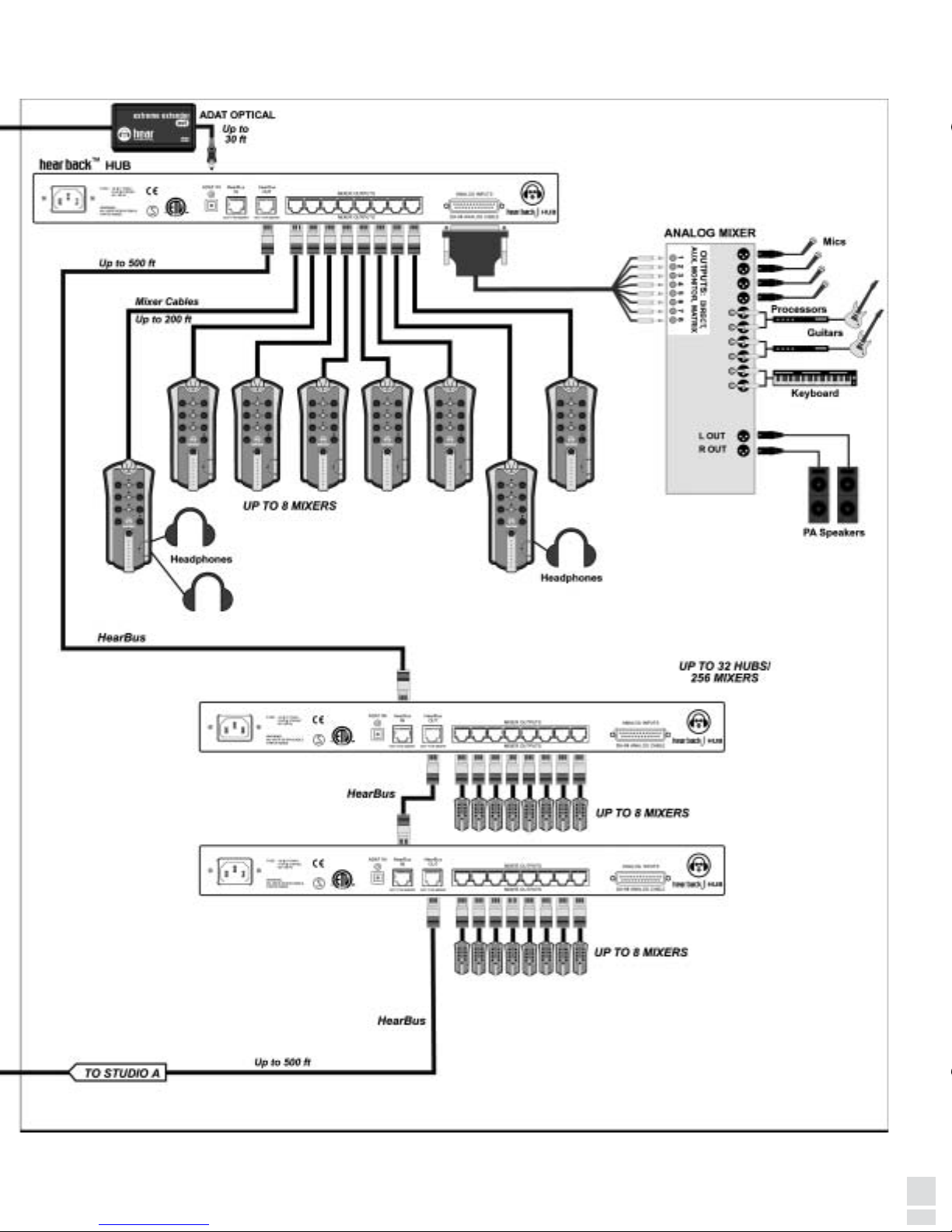
How to parallel channels 1 & 2
(stereo inputs) across multiple
"Master Hubs" as shown in
the "Large Stereo System"
hook-up diagram on page 15
After connecting the stereo mix to channels 1 and 2 at each hub - Connect master hub #1, channels 3-
8 for band mix, connect master hub #2, channels 9-14 for vocals section, connect master hub #3,
channels 15-20 for horns ... you get the idea, right! By using the HearBus outputs on the master hubs
and connecting them to the slave hub HearBus inputs, you can obtain as many mixing stations of each
master mix as desired. Since each hub may be daisy chained a minimum of 32 times, this example
system yields 3 master hubs x 32 slave hubs = 96 hubs, then 96 x 8 = 768 mixers!
NOTE: When "Y" connecting multiple hub inputs, one must be concerned with the total impedances.
The hub inputs are 18K ohms balanced. Since the input to output impedance ratio should be at or
above 10:1, there are a couple of rules to follow: Assuming a mixer source impedance of 180 ohms,
the following applies: 18000/1800 = 10.
Where: 18000 = source impedance
1800 equals ten times your source impedance
10 = 18000/1800 is the number of hubs that meet the required impedance
Therefore, you can parallel up to ten master hubs to a quality BALANCED line output. In the event you
experience problems or if you have an unbalanced output, obtain a high quality, balanced audio
distribution system. We don't recommend using unbalanced sources for this connection scheme as
hum loops will occur.
NOTE: The HearBus and mixer outputs contain high speed digital audio and should be treated as a transmission line.
DO NOT "Y" these connections because the terminated controlled impedance will be comprised.
The HearBus and mixer outputs operate at 12.28 MHz.
If you need further assistance, feel free to contact Hear Technologies technical support at 1-256-922-1200.
0912
Page 10

Page 11
1110
Page 12

Page 13
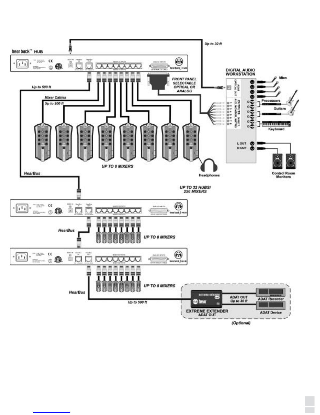
HOOK-UP DIAGRAM DIGITAL AUDIO WORKSTATION
1308
Page 14

Page 15
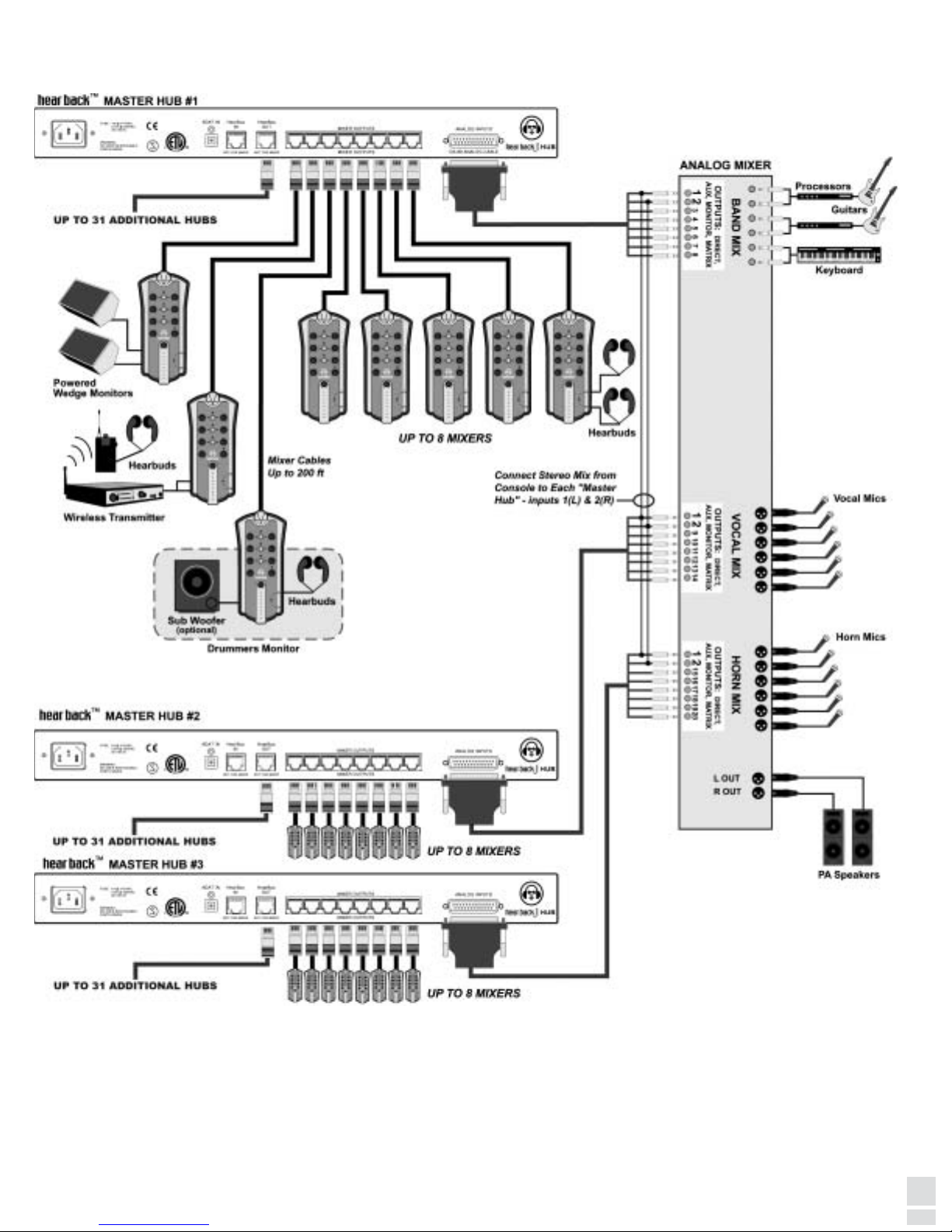
HOOK-UP DIAGRAM LARGE STEREO SYSTEM - ANALOG
NOTE: Each hub gets the stereo mix and sectionals.
Each master hub can have 31 hubs daisy-chained from it.
1506
Page 16

Page 17
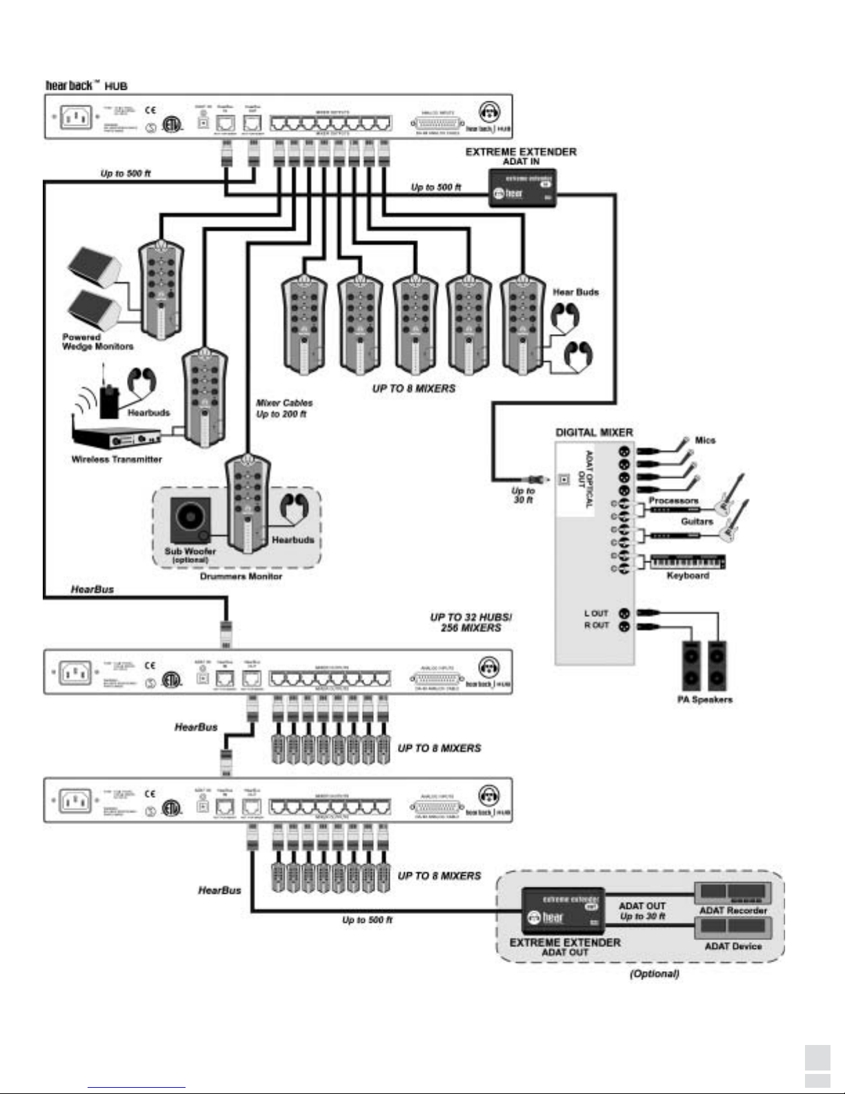
HOOK-UP DIAGRAM STEREO LIVE - DIGITAL
1704
Page 18

Page 19
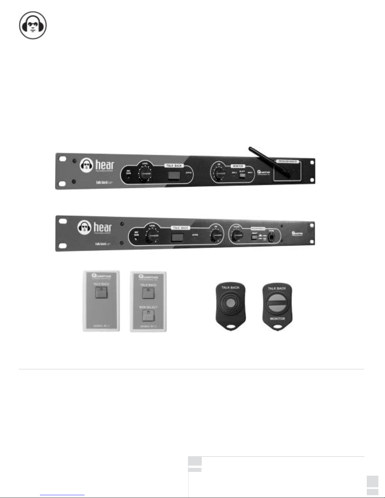
TALK BACK 600
TALK BACK 200
OTHER HEAR TECHNOLOGIES PRODUCTS
RC-1 RC-2
wired remotes
(optional for models 200 & 600)
wireless remotes
(optional for model 600 only)
RF-1
RF-2
TALK BACK
The Talk Back models 200 and 600, add talk back
capability and control room monitor dimming to recording
consoles, digital audio workstations, and portable audio
workstations. Optional wired and wireless remotes (single
and dual-button versions) are available for control of the
talk back and/or monitor select functions. In addition to
these features, the model 600 has control room monitor
switching and optional wireless RF remote control.
The Talk Back permits the engineer to control talk back
and monitor switching from: the front panel switches, the
wired remotes, and the RF wireless remotes (600 only).
Applications include professional recording studios,
project studios, and video post-production facilities. The
unit's features and audio specifications rival or surpass
those found in large format recording consoles.
Quantum Technologies, Inc. (QTI) warrants the equipment against defects in materials and labor for a period of one year from the original date of purchase. The duration of this warranty
is limited to claims made to QTI within the periods stated with respect to parts and labor from the date of purchase. During the warranty period, defective equipment will be replaced or
repaired to the general condition as received, at the discretion of QTI.
All transportation is the responsibility of the purchaser or owner. Equipment should be shipped in the original shipping box.
This warranty applies only to defects in materials and workmanship and does not cover failure or damage due to shipping loss or damage, abuse, misuse, misapplication, incorrect or
varying power line voltages, lack of proper maintenance, natural disasters, acts of God, or unauthorized modifications, repairs, or any alterations done without the expressed written
consent by QTI. QTI shall not be liable for any loss of use of the equipment, or consequential damages, including damages to other parts of the installation in which the equipment is a
part.
QTI does not make any warranty, express or implied, other than the warranty contained herein. No agent, representative, or employee has the authority to increase or alter the liability,
obligations, and terms of this warranty or sale of the equipment. NOTE: It is strongly recommended that any equipment returned to QTI be properly packaged and insured for its full
value in case of loss, handling or shipping damage.
QTI shall not be responsible for damage or loss of equipment during shipment.
The following are registered trademarks of Hear Technologies: Hear
Technologies, Hear Back, Talk Back, Extreme Extender, Hearbuds, HearBus,
and the "Jack" logo. All names and marks of other companies belong to
those respective companies.
LIMITED WARRANTY
19
Page 20

 Loading...