

Page 1

ARB Approved IOM – Executive Orders VR-201-B and VR-202-B (Wayne Harmony WayneVac Dispen ser) Page 103
WAYNE-DRESSER HARMONY™ SERIES DISPENSER
RETROFIT for HEALY SYSTEMS, INC.
MODEL VP1000
VAPOR RECOVERY ASSIST SYSTEM
(KIT Z080)
OUTLINE
NOTICE: USE THIS PROCEDURE IF CONVERTING A WAYNE-VAC™ VAPOR RECOVERY
ASSIST SYSTEM TO A HEALY VAPOR RECOVERY ASSIST SYSTEM
See Healy Systems Kit Z078 For Dispensers With Balance Systems
1. Purpose
2. Safety
3. Models Covered
4. Parts Lists
5. Tools Required
6. Dispenser Access
7. Survey Scope Of Work
8. Wayne-VAC Removal
9. Installing The Healy VP1000 System
10. Connecting Vapor Lines
11. Installing The Sealed Nipple Assembly
12. Wiring Inside The Electronics Compartment
13. Connecting Healy Systems Dispensing Equipment
14. VP1000 Theory Of Operation
15. Testing The System
16. Trouble Shooting The VP1000
17. VP1000 Vane & Rotor Service & Replacement Guide
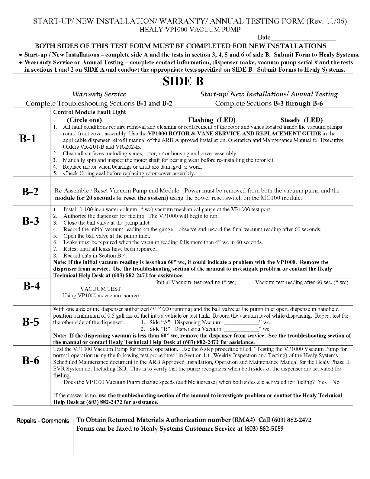
Start-up / New Installation / Warranty / Annual Testing Form (Rev. 11/06)
Healy Systems, Inc. Website: http://www.healysystems.com
18 Hampshire Drive Email: [email protected]
Hudson, New Hampshire 03051 USA Telephone: 603.882.2472
ARB Approved Installation, Operation and Maintenance Manual (November 2006) Fax: 603.882.5189
Healy Systems, Inc. – the innovative leader of Stage II vapor recovery equipment
Page 2

ARB Approved IOM – Executive Orders VR-201-B and VR-202-B (Wayne Harmony WayneVac Dispen ser) Page 104
1. PURPOSE:
This procedure describes the tools, methods and skill levels required to install a Healy
Systems, Inc. Model VP1000 Vapor Recovery pump in vapor ready Wayne Dresser Harmony™
series gasoline dispensers. Only Healy trained and certified contractors will be able to perform
these retrofits or warranty will be void. The installer shall be a skilled petroleum technician and
thoroughly familiar with the requirements of State, Federal and local codes for installation and
repair of gasoline dispensing equipment. Also, they shall be aware of all the necessary safety
precautions and site safety requirements to assure a safe and trouble free installation. NOTE:
All electrical and hydraulic plumbing fittings referred to in these instructions must be UL
“listed” or “recognized” for the purpose.
2. SAFETY: Before installing the equipment, read, understand and follow:
- The National Electrical Code (NFPA 70)
- The Automotive and Marine Service Code (NFPA 30A)
- Any national, state and local codes that may apply.
The failure to install the equipment in accordance with NFPA 30A and
70 may adversely affect the safe use and operation of the system.
3. MODELS COVERED:
Wayne-Dresser Harmony™ series dispensers, all options except suffix “O”, non vapor
ready and Balance systems. The addition of the Healy Systems VP1000 to the Harmony
Accurate, sound installations reduce service calls: Use experienced,
licensed contractors that practice accurate, safe installation
techniques. Careful installation provides a sound troubleshooting
framework for field repairs and can eliminate potential problems.
1. Read all instructions before beginning.
2. Follow all safety precautions:
Barricade the area.
Do not allow vehicles or unauthorized people in the area.
Do not smoke or allow open flames in the area.
Do not use power tools in the work area.
Wear eye protection during installation.
3. Use circuit breakers for multiple disconnects to turn off power and
prevent feedback from other dispensers.
Healy Systems, Inc. Website: http://www.healysystems.com
18 Hampshire Drive Email: [email protected]
Hudson, New Hampshire 03051 USA Telephone: 603.882.2472
ARB Approved Installation, Operation and Maintenance Manual (November 2006) Fax: 603.882.5189
Healy Systems, Inc. – the innovative leader of Stage II vapor recovery equipment
Page 3

ARB Approved IOM – Executive Orders VR-201-B and VR-202-B (Wayne Harmony WayneVac Dispen ser) Page 105
dispenser will increase the current draw of the dispenser by 2 amps. Use the label
supplied to note this change.
4. PARTS LISTS: (See Photo A)
1 VP1000 Vacuum Pump
1 1365A Wire Harness / MC100 Series Interface Module Assembly
Photo A Photo B
Photo C Photo D
HARDWARE KIT Z080H: (See Photo B)
2 1/4-20 bolts, washers, lock washers and nuts
Healy Systems, Inc. Website: http://www.healysystems.com
18 Hampshire Drive Email: [email protected]
Hudson, New Hampshire 03051 USA Telephone: 603.882.2472
ARB Approved Installation, Operation and Maintenance Manual (November 2006) Fax: 603.882.5189
Healy Systems, Inc. – the innovative leader of Stage II vapor recovery equipment
Page 4

ARB Approved IOM – Executive Orders VR-201-B and VR-202-B (Wayne Harmony WayneVac Dispen ser) Page 106
ELECTRICAL KIT Z080E: (See Photo C)
4 4” Tyraps
1 Current change label (p/n 1405)
7 Wire nuts
1 8-32 x 3/4” machine screw, washer & nut
1 1/2” male NPT x 3/4” female NPT electrical reducer fitting
1 #1346 potted conduit nipple
1 #8 Ring tong terminal
1 Notice label (p/n 1406)
1 UL Listed label (p/n 1410)
VAPOR KIT Z080V: (See Photo D)
2 3/8” NPT x 5/8” flare straight fittings
3 1/2” NPT x 5/8” flare elbow fittings
1 1/2” NPT x 5/8” flare straight fitting
3 3/4” NPT x 5/8” flare straight fittings
1 5/8” x 5/8” x 5/8” flare tee
12’ 5/8” OD copper tube, type ‘L’
1 1/4” pipe plug
1 3/8” pipe plug
1 1/2” close nipple
1 1/2” x 1/4” x 1/2” reducing tee
1 1/2” ball valve
1 3/4” elbow
12 5/8” flare nuts
MATERIALS SUPPLIED BY INSTALLER:
Thread Sealing Compound – non-Setting, UL Classified for use on all tapered
thread, Non-electrical, plumbing fittings.
Teflon tape
Healy Systems, Inc. Website: http://www.healysystems.com
18 Hampshire Drive Email: [email protected]
Hudson, New Hampshire 03051 USA Telephone: 603.882.2472
ARB Approved Installation, Operation and Maintenance Manual (November 2006) Fax: 603.882.5189
Healy Systems, Inc. – the innovative leader of Stage II vapor recovery equipment
Page 5

ARB Approved IOM – Executive Orders VR-201-B and VR-202-B (Wayne Harmony WayneVac Dispen ser) Page 107
5. TOOLS REQUIRED:
1/2” or 3/8” ratchet set w/ sockets 1/4” through 9/16” + 3” extension
9” lineman’s pliers
Assorted open end wrenches 1/4” through 3/4”
Wire cutters/strippers 18 AWG and 26 AWG
1-1/8” greenlee type sheet metal punch
Mechanical hand drill (egg-beater type)
Assorted drill bits 1/16” through 7/16”
Assorted screwdrivers (flat blade-one must be 1/8” wide and Phillips)
5/8” copper tube bending tool
5/8” copper tube flaring tool
Copper tubing cutter
Electrical multi-meter
Small hand brush (1-1/2” thick, for clearing chips)
12” adjustable wrench
10” pipe wrench
Tape measure
Allen wrenches
#20 torx bit
Whitney type hand sheet metal punch with 3/16” punch and die set
6. DISPENSER ACCESS:
Secure Dispenser Access keys from Station Management.
Lock-out and tag-out all electrical power to dispenser being modified.
Remove the Top Cladding and Upper Shield in order to expose upper vapor tubing
attached to the outlet castings.
Remove both Upper Column Covers above nozzle holsters in order to expose Wayne-
VAC™ vacuum pumps.
Remove the Lower Column Cover below the nozzle holster on the “A” side of the
dispenser. This is the side that the vapor tubes from the out port of the Wayne-VAC™
vacuum pumps are connected to a vapor tee mounted at the base of the dispenser, see
photo F.
Remove the Upper Cladding covering the “J” Box, see photo E.
Healy Systems, Inc. Website: http://www.healysystems.com
18 Hampshire Drive Email: [email protected]
Hudson, New Hampshire 03051 USA Telephone: 603.882.2472
ARB Approved Installation, Operation and Maintenance Manual (November 2006) Fax: 603.882.5189
Healy Systems, Inc. – the innovative leader of Stage II vapor recovery equipment
Page 6

ARB Approved IOM – Executive Orders VR-201-B and VR-202-B (Wayne Harmony WayneVac Dispen ser) Page 108
Remove the “J” Box cover.
Remove the Door Cladding assembly and the Access Door assembly in order to expose
the electronics compartment.
7. SURVEY– Scope of Work: Perform this step before beginning steps 8 thru 12.
Read and familiarize yourself with the theory of operations sheet and wiring instructions for the
VP1000 Vapor Pump. The installation of the pump is on the sheet metal shelf over the junction
box, with the pump cover facing the “A” side of the dispenser, see photo E. This is the side
that the vapor tubes from the out port of the Wayne-VAC™ vacuum pumps are connected to a
vapor tee mounted at the base of the dispenser, see photo F. From this survey, you will have
an indication of where the vapor plumbing fittings need to go and where the holes need to be
drilled in the adjoining sheet metal to allow the vapor pipes from the pump to pass through to
the hydraulics compartment. Notice also in the electrical junction box, on the bottom right
side, there is a potted conduit nipple which contains the Wayne-VAC™ wiring harness (for
pump on “A” side) that you will remove to install the Healy potted conduit nipple, See Section
11. CAUTION: ALL POWER TO DISPENSER UNDER MODIFICATION SHOULD BE COMPLETELY
DISCONNECTED AND CAPPED OFF AT JUNCTION BOX TO AVOID UNINTENTIONAL
FEEDBACK FROM OTHER DISPENSERS!!
Photo E Photo F
8. WAYNE-VAC™ REMOVAL:
Disconnect and lockout the power to the dispenser.
Open the dispenser cabinet doors as specified in section 6 above.
Healy Systems, Inc. Website: http://www.healysystems.com
18 Hampshire Drive Email: [email protected]
Hudson, New Hampshire 03051 USA Telephone: 603.882.2472
ARB Approved Installation, Operation and Maintenance Manual (November 2006) Fax: 603.882.5189
Healy Systems, Inc. – the innovative leader of Stage II vapor recovery equipment
Page 7
ARB Approved IOM – Executive Orders VR-201-B and VR-202-B (Wayne Harmony WayneVac Dispen ser) Page 109
Close the vapor recovery (Stage ll Vapor return line) impact valve. If there is no
impact valve, be sure to have proper plugs or caps available to plug the Stage ll line
before disconnecting the Wayne-VAC™ equipment.
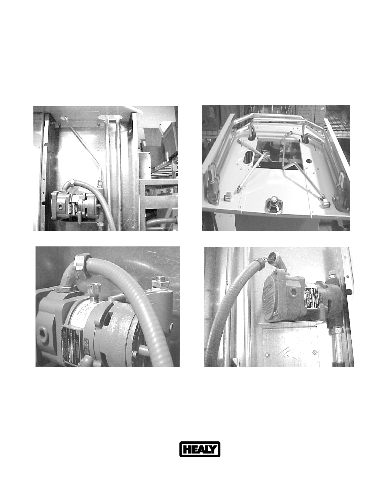
Unscrew the flare nuts holding the vapor tube into the inlet of both VAC pumps, see
photo G.
Unscrew the flare nuts from the vapor port of both outlet castings and remove the
vapor tubes, see photo H.
Remove the 3/8” NPT x 3/8” flare elbow fittings from both outlet castings, see photo H.
Photo G Photo H
Photo I Photo J
Remove the 3/8” NPT x 3/8” flare straight fitting from the inlet of the VAC pump on the
“B” side and install the 3/8” pipe plug supplied in the Healy Vapor Kit, tighten
securely, see photo I.
Healy Systems, Inc. Website: http://www.healysystems.com
18 Hampshire Drive Email: [email protected]
Hudson, New Hampshire 03051 USA Telephone: 603.882.2472
ARB Approved Installation, Operation and Maintenance Manual (November 2006) Fax: 603.882.5189
Healy Systems, Inc. – the innovative leader of Stage II vapor recovery equipment
Page 8

ARB Approved IOM – Executive Orders VR-201-B and VR-202-B (Wayne Harmony WayneVac Dispen ser) Page 110
On the “A” side VAC pump, back off the electrical nut from the elbow attached to the
pump and the flare nut holding the vapor tube in the out port of the pump, see
photo J.
Remove the (3) sheet metal screws that hold the pump to the bracket.
Remove the electronics cover, secured with (4) bolts, from the pump.
Disconnect harness wires from the pump wires and pull through the elbow. Let the
electrical tube hang for future use. Remove the elbow and set aside for future use.
Lift the VAC pump off the outlet vapor tube and set aside.
Remove the VAC pump mounting bracket.
Unscrew the flare nut holding the outlet vapor tube in the bottom of the dispenser and
remove the vapor tubing, see photo F, right side when facing the dispenser.
Remove the 3/4” NPT flare fitting from the 3/4” elbow and install a 3/4” NPT x 5/8” flare
straight fitting supplied in the Healy Vapor Kit, tighten securely.
In the “J” box, bottom right, you will see the potted nipple containing the wire harness
that was previously disconnected from the Wayne-VAC™ pump. Follow this harness
from the bottom of the potted nipple (under the “J” box) to the Wayne-VAC™
electronics control board #887227; remove the (2) connectors from the board and also
the green ground wire attached to the chassis.
Remove the coupling (under the “J” box) from the potted nipple and wire harness that
was just disconnected from the Wayne-VAC™ electronics control board #887227.
Remove the potted nipple from the “J” box and pull the wire harness out of the
flexible, non-metallic electrical tubing and elbow, set aside.
IMPORTANT: In the “J” box, bottom left, you will see the potted nipple containing the
wire harness that controls the Wayne-VAC™ pump on the “B” side of the dispenser.
Follow this harness from the bottom of the potted nipple (under the “J” box) to the
Wayne-VAC electronics control board #887227, remove the (2) connectors from the
board and neatly bundle up out of the way.
WARNING
This retrofit kit requires drilling in a Hazardous Location. Insure that all power to the dispenser
has been turned off. Open all access doors for increased airflow. Use only sharp drill bits; dull
bits may generate excessive heat. Use air powered drill at low RPM’s. If an electric drill is
used, a suitable UL Listed Gas Detector must be used to ensure the area is below 25% of the
Lower Explosive Limit. Do not drill if gasoline odors are present.
If drilling in the electronics cabinet, carefully collect and remove all metal shavings that may be
inside the cabinet. Failure to remove the shavings could result in an electrical shock hazard.
Before drilling, check to ensure that no wires or fluid containing parts (i.e. product tubing) is
located on the backside or near the chuck of the drill.
Healy Systems, Inc. Website: http://www.healysystems.com
18 Hampshire Drive Email: [email protected]
Hudson, New Hampshire 03051 USA Telephone: 603.882.2472
ARB Approved Installation, Operation and Maintenance Manual (November 2006) Fax: 603.882.5189
Healy Systems, Inc. – the innovative leader of Stage II vapor recovery equipment
Page 9

ARB Approved IOM – Executive Orders VR-201-B and VR-202-B (Wayne Harmony WayneVac Dispen ser) Page 111
9. INSTALLING THE HEALY VP1000 SYSTEM
NOTICE: WHEN DRILLING HOLES, ASSURE THAT THERE ARE NO HAZARDOUS
VAPORS PRESENT AND DO NOT ALLOW CHIPS TO FALL DOWN INTO THE
HYDRAULICS AREA.
In order to get the vapor tubing from the pump into the vapor plumbing area, it is
necessary to drill or punch two 1-1/8” holes on the sheet metal column near the edge
of the shelf, see photo E. Use a tape measure and mark the centerline of the holes to
be 1-1/4” in from the front edge of the sheet metal column. Measure down from the
top of the column 5-1/2” and mark on the 1-1/4” centerline, measure down an
additional 6-3/4” and mark on the centerline. These marks are the centers of the holes
for the vapor pipes going to the VP1000. DO NOT DRILL – verify positions in the next
steps.
Get the vapor pump and install a 1/2” NPT x 5/8” flare elbow fitting into the ‘IN’ and
‘OUT’ ports using tape, not pipe dope. Looking at the face of the pump, completely
tighten both fittings so they are facing the right.
Position the pump on top of the sheet metal shelf over the electrical junction box on
top of the electronics cabinet, with the fittings pointing toward the hydraulics cabinet
and overhanging the edge of the shelf about 1/4”.
Slide the pump to fit against the hydraulics cabinet and position so as to allow for
matching the location of holes that need to be drilled through the sheet metal.
Satisfied that the fittings and hole marks line up, remove the pump and drill the two,
1-1/8” holes, marked above.
Position the pump assembly on top of the sheet metal shelf and slide over so that the
ports are accessible from the hydraulics area.
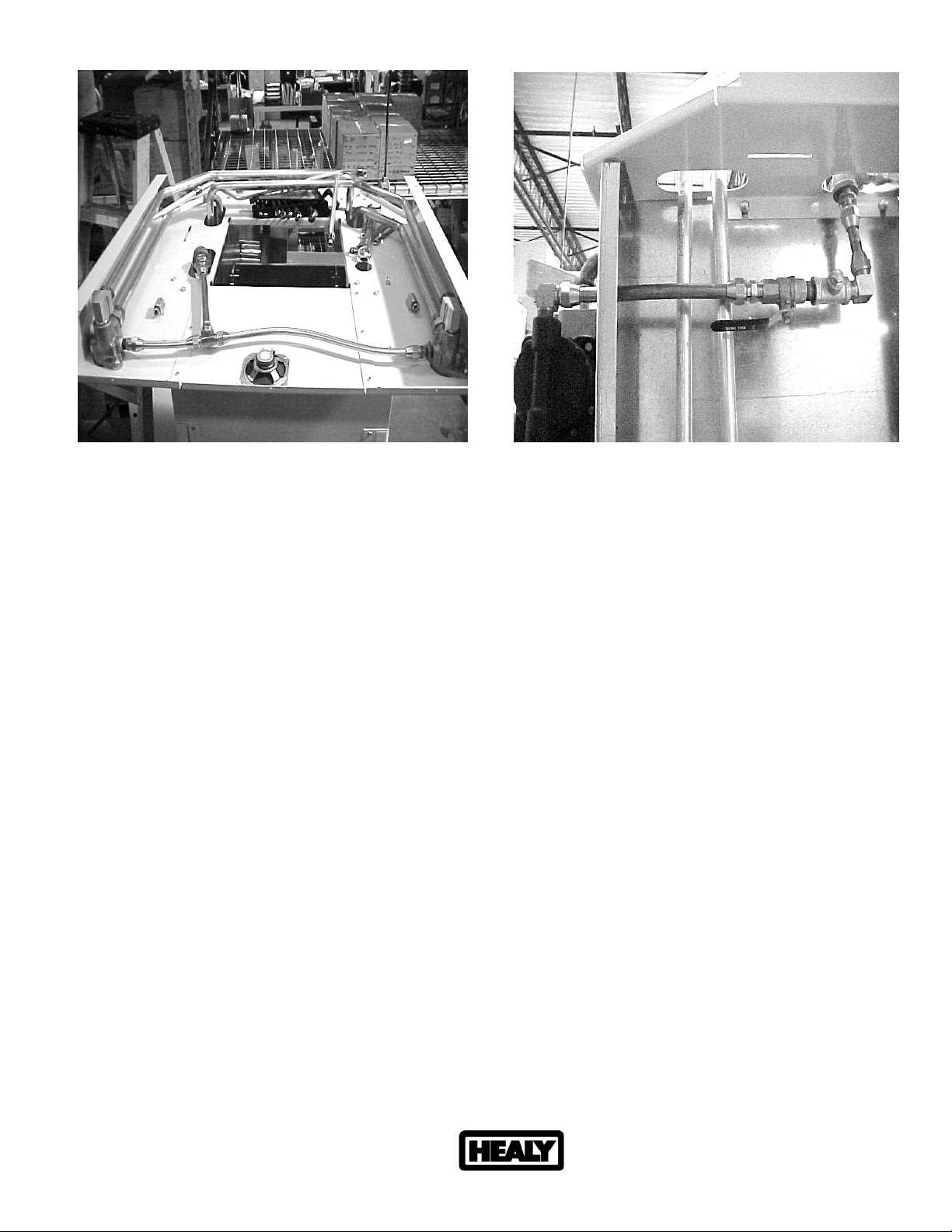
10. CONNECTING VAPOR LINES: (See Photos K, L, M & N)
NOTICE: ALL VAPOR LINES MUST BE INSTALLED TO BE NATURALLY DRAINING,
WITHOUT ANY DIPS OR TRAPS THAT WOULD CAUSE BLOCKAGE.
Healy Systems, Inc. Website: http://www.healysystems.com
18 Hampshire Drive Email: [email protected]
Hudson, New Hampshire 03051 USA Telephone: 603.882.2472
ARB Approved Installation, Operation and Maintenance Manual (November 2006) Fax: 603.882.5189
Healy Systems, Inc. – the innovative leader of Stage II vapor recovery equipment
Page 10
ARB Approved IOM – Executive Orders VR-201-B and VR-202-B (Wayne Harmony WayneVac Dispen ser) Page 112
Photo K Photo L
Install a 3/8” NPT x 5/8” flare straight fitting into the vapor port of both outlet castings,
see photo K.
Install a 3/4” NPT x 5/8” flare straight fitting into each end of the 3/4” elbow supplied in
the Healy vapor kit.
Make up (3) pieces of 5/8” OD tube and attach as shown in photo K. The lengths are
approximately as follows: 15-1/2” from the right outlet casting, 4-1/2” from the left outlet
casting and 10” from the 3/4” elbow to the tee. Do not block column area.
Make up the following assembly, see photo L. Note: The ball valve handle closes toward
you. Install a 1/2” NPT x 5/8” flare straight fitting to the left side of the ball valve, install
the 1/2” close nipple to the right side then the 1/2” reducing tee and the 1/2” NPT x 5/8”
flare elbow – completely tighten the tee with the 1/4” branch facing up and the elbow also
facing up, install the 1/4” pipe plug into the branch.
Make up a piece of 5/8” OD copper tube that will go from the flare elbow on the inlet of
the VAC pump, through the upper 1-1/8” hole in the column to the straight flare fitting on
the ball valve assembly so that when installed and secured, positions the flare elbow on
the ball valve assembly in a straight line with the straight flare fitting that’s attached to
the 3/4” elbow of the upper vapor manifold. Install and tighten with the ball valve
assembly in position as shown in photo L.
Make up a piece of 5/8” tube to connect the flare elbow on the ball valve assembly to the
straight flare fitting that’s attached to the 3/4” elbow of the upper vapor manifold. This
piece should be made so that when installed the ball valve assembly and tubing should
be horizontal or slightly pitched toward the pump to avoid liquid traps. Install and
tighten.
Healy Systems, Inc. Website: http://www.healysystems.com
18 Hampshire Drive Email: [email protected]
Hudson, New Hampshire 03051 USA Telephone: 603.882.2472
ARB Approved Installation, Operation and Maintenance Manual (November 2006) Fax: 603.882.5189
Healy Systems, Inc. – the innovative leader of Stage II vapor recovery equipment
Page 11
ARB Approved IOM – Executive Orders VR-201-B and VR-202-B (Wayne Harmony WayneVac Dispen ser) Page 113
Mark the location of the mounting bolt holes from the VAC pump base on the shelf,
unscrew the flare nut on the inlet and move the VAC pump out of the way. Drill two 5/16”
holes (one on each side of the bracket) required for mounting the pump.
Reposition the VAC pump and reconnect the flare nut to the inlet port, then install the
two 1/4-20 bolts, washers, lock washers and nuts to secure the pump.
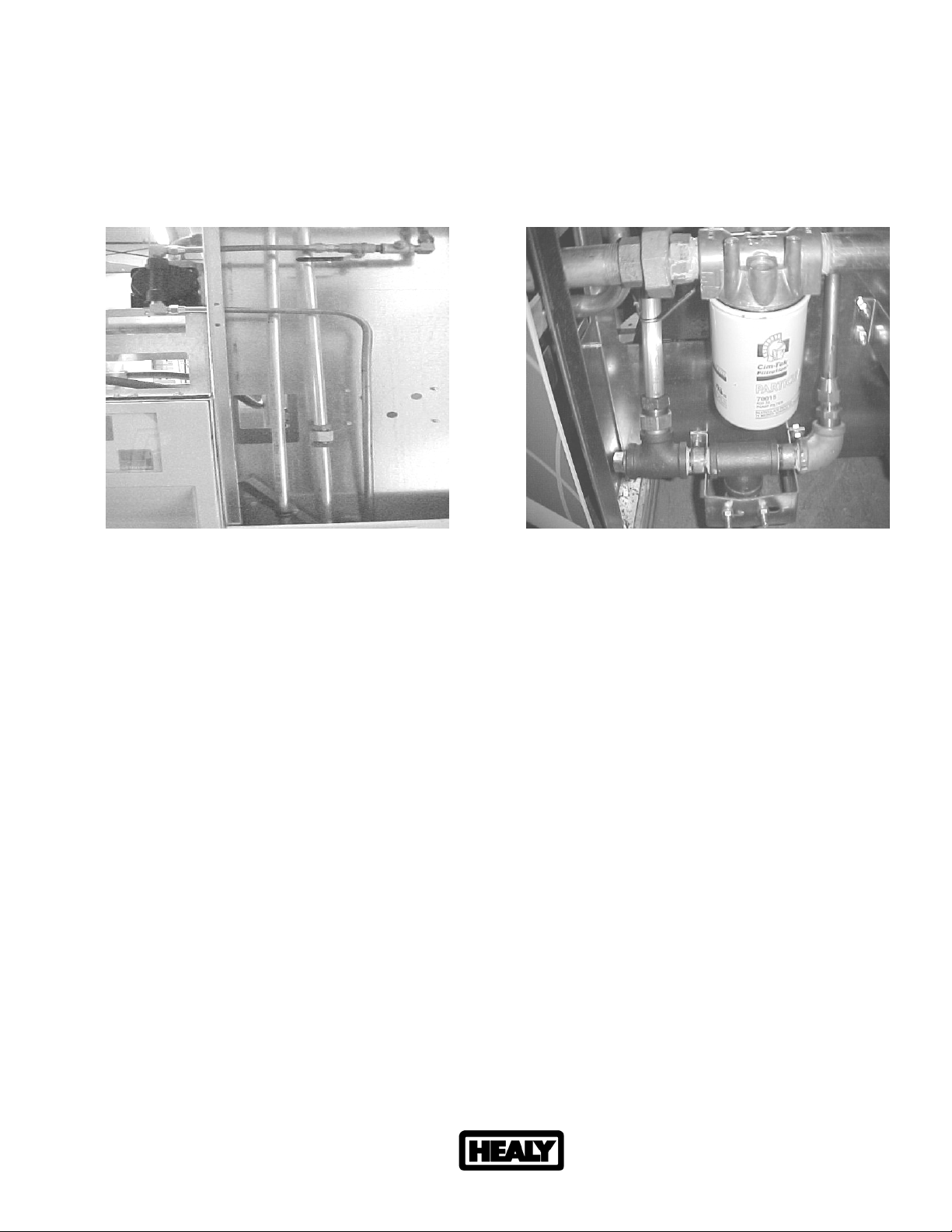
Photo M Photo N
Measure and cut appropriate length of 5/8” tubing to reach from the 5/8” flare elbow on
the outlet of the VAC pump, through the lower 1-1/8” hole in the column to the 5/8” flare
straight fitting installed in the 3/4” elbow at the base of the dispenser, using a 90 degree
bend, see photos M & N.
Install and tighten making sure the horizontal portion of the tube attached to the outlet is
either horizontal or slightly pitched downward away from the pump to avoid liquid traps.
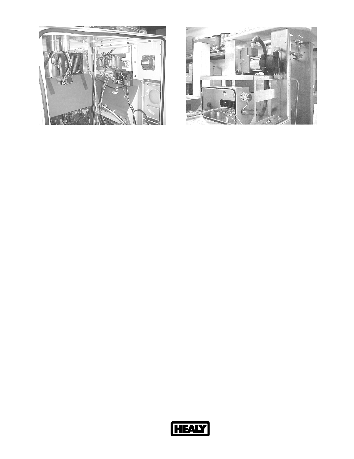
11. INSTALLING THE SEALED NIPPLE ASSEMBLY: (See Photos O & P)
NOTICE: THE INTERFACE MODULE THAT IS SUPPLIED HAS A HARNESS
ATTACHED AND A WIRING PLUG FOR THE AC CONNECTIONS. ALSO SUPPLIED IS
THE SEALED NIPPLE ASSEMBLY (1346) THAT MUST BE USED BETWEEN THE DIVISION
1 AREA (THE ELECTRONICS COMPARTMENT) AND THE DIVISION 2 AREA (THE SPACE
ABOVE AND OUTSIDE THE ELECTRONICS COMPARTMENT).
Healy Systems, Inc. Website: http://www.healysystems.com
18 Hampshire Drive Email: [email protected]
Hudson, New Hampshire 03051 USA Telephone: 603.882.2472
ARB Approved Installation, Operation and Maintenance Manual (November 2006) Fax: 603.882.5189
Healy Systems, Inc. – the innovative leader of Stage II vapor recovery equipment
Page 12
ARB Approved IOM – Executive Orders VR-201-B and VR-202-B (Wayne Harmony WayneVac Dispen ser) Page 114
Photo O Photo P
Get the 1346 sealed nipple assembly and carefully remove the first nut and washer over
the wires. Thread these wires from inside the electronics compartment, up through the
hole inside the ”J” box, (bottom right) where the Wayne VAC™ potted nipple was
removed. Carefully replace the washer and nut over the wires and secure the unit into
the box.
At the VP1000, get and install the 1/2” male x 3/4” female adaptor over the wires coming
from the motor. Do not use pipe dope on these fittings and be sure there is at least five
full threads of engagement of the fittings in their respective couplings.
Thread the pump wires through the elbow that was removed from the Wayne VAC™
motor electronics housing and screw the threaded end with the “O” ring into the 1/2”
male x 3/4” female adaptor installed in the above step. Tighten so that the elbow faces
away from the “J” box, see photo P.
Get the electrical tube that was left hanging during the Wayne VAC™ removal, and route
up to the VP1000 VAC pump as shown in photo P.
Run the electronic wires from the VP1000 through the electrical tube and into the “J” box
as shown. Reconnect the electrical tube to the elbow on the VAC pump.
In the “J” box, leave about 6” of wire on both the wires coming from the motor and from
the sealed nipple, cut off excess wire and strip approximately 1/2” of insulation from all
wires.
Use wire nuts to join the wires, color for color, together. There may be some extra wires
in some sealed nipples, cap these off and dress aside.
Keep wires clear of pinch points and from interference, make sure no wires overhang the
door openings.
Replace the cover on the junction box.
Healy Systems, Inc. Website: http://www.healysystems.com
18 Hampshire Drive Email: [email protected]
Hudson, New Hampshire 03051 USA Telephone: 603.882.2472
ARB Approved Installation, Operation and Maintenance Manual (November 2006) Fax: 603.882.5189
Healy Systems, Inc. – the innovative leader of Stage II vapor recovery equipment
Page 13
ARB Approved IOM – Executive Orders VR-201-B and VR-202-B (Wayne Harmony WayneVac Dispen ser) Page 115
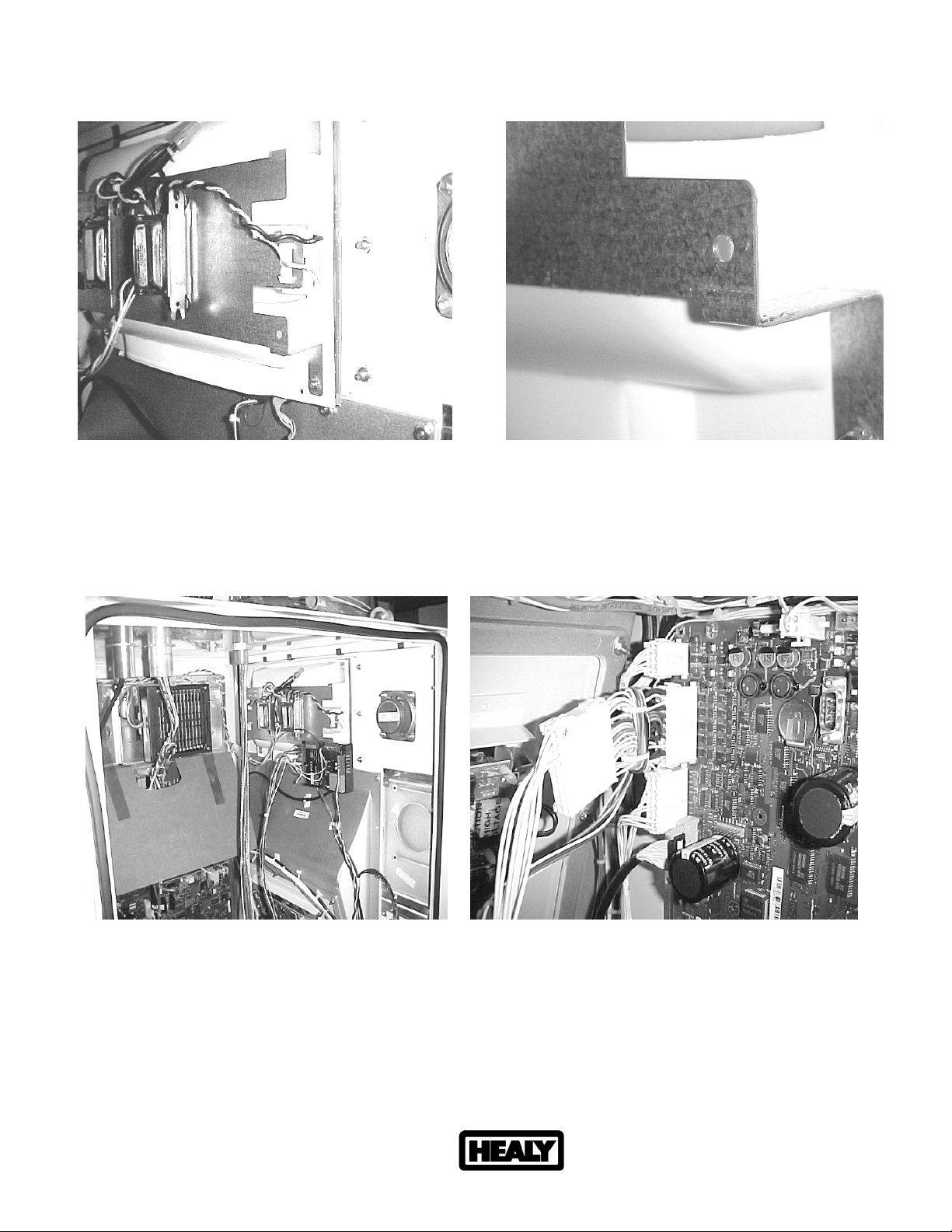
12. WIRING INSIDE THE ELECTRONICS COMPARTMENT: (See Photos Q, R, S, & T)
Photo Q Photo R
In the electronics bay, locate the light assembly on the upper right side of the cabinet,
see photo Q. In photo R, notice the 3/16” hole that must be made to accept the module
mounting screw. Punch this hole approximately as shown. If drilling, be sure no
hazardous vapors are present and use a coffee cup or other suitable container to prevent
metal chips from falling inside the cabinet.
Photo S Photo T
Leave the wires coming from the sealed nipple assembly at least six inches longer than
necessary to reach the bottom of the compartment. Cut off excess and strip all wires
1/2”.
Healy Systems, Inc. Website: http://www.healysystems.com
18 Hampshire Drive Email: [email protected]
Hudson, New Hampshire 03051 USA Telephone: 603.882.2472
ARB Approved Installation, Operation and Maintenance Manual (November 2006) Fax: 603.882.5189
Healy Systems, Inc. – the innovative leader of Stage II vapor recovery equipment
Page 14

ARB Approved IOM – Executive Orders VR-201-B and VR-202-B (Wayne Harmony WayneVac Dispen ser) Page 116
Connect the wires from the sealed nipple to the interface module as follows:
Black wire to ‘motor ‘ on module
White wire to ‘neutral’ on module
Red wire (either) to ‘output 1’ on module
Red wire (other) to ‘output 2’ on module
Orange wire to ‘fault common’ on module
Purple wire to ‘fault input’ on module
Green wire needs a #8 ring tong lug installed and connected to any chassis ground
(frame)
Some sealed nipples may have some extra wires, cap these and bundle them
neatly out of the way.
The black and white twisted pair of wires with a connector should be connected to an
available AC outlet on the dispenser Relay Board #887225.
The male/female multiconductor cable that is wired to the interface module is routed up
to the computer board # 173976, see photo T. Disconnect the valves cable that’s in the
J3 connector and install in the female side of the double connector on the harness. The
entire assembly is then installed back into J3 on the Computer board. WIRING IS
COMPLETE.
Mount the interface module as shown in Photo S using the 8-32 x 5/8” screw, washer and
nut supplied in the electrical kit.
Install the following labels supplied:
• NOTICE label for current increase (1405), install on the frame rail near the
existing power consumption label.
• Large NOTICE label (1406) relating to the vapor recovery upgrade and how to
reset the electronic module should be installed near the module, where it will be
readily visible to a service technician on the junction box cover.
• UL, retrofit kit identification number (1410), install on the electronic module.
13. CONNECTING HEALY SYSTEMS DISPENSING EQUIPMENT
Completing the connection of Healy Systems dispensing equipment requires the
installation of Healy Systems Phase II dispenser adaptors, hoses and nozzles
(Hanging Hardware).
If applicable, remove existing non-Healy hanging hardware (from the dispenser
product outlet adaptor to and including the nozzles).
Healy Systems, Inc. Website: http://www.healysystems.com
18 Hampshire Drive Email: [email protected]
Hudson, New Hampshire 03051 USA Telephone: 603.882.2472
ARB Approved Installation, Operation and Maintenance Manual (November 2006) Fax: 603.882.5189
Healy Systems, Inc. – the innovative leader of Stage II vapor recovery equipment
Page 15

ARB Approved IOM – Executive Orders VR-201-B and VR-202-B (Wayne Harmony WayneVac Dispenser) Page 117
Vapor ready dispensers will require a Healy Systems adaptor to make the hose
threads compatible with other Healy Systems equipment. Install following
instructions packed with the adaptor. Various adaptors and pigtails are available,
depending on how the dispenser is configured: M34 metric (Healy designation F3 or
S3) or balance ready (Healy designation S4).
Healy Vapor Recovery Hoses are available in various lengths to satisfy local
ordinances and still provide “far side” fueling capability. Install these following
instructions contained on the shipping box.
Breakaways are required: Install either Model 8701-VV breakaway or Model 807
swivel breakaway; install using the instructions supplied with the unit.
The Healy Systems nozzle Model 900 (EVR) is the only nozzle necessary to complete
the upgrade. Check to be sure the nozzle hanger is mounted in the highest position.
Be sure to check for proper fit in the nozzle holster and that the nozzle can be locked
in the off position. Also, be sure that when the nozzle is locked, that the dispenser
can not be activated from the locked position.
14. VP1000 THEORY OF OPERATION
The Healy Systems VP1000 is a self-contained rotary vane pump, designed for gasoline vapor
recovery utilizing various parts of the Healy System Vapor Recovery product line. It is intended
for use by either OEM dispenser/pump manufacturers or as an after market add-on to make
existing equipment compatible with Healy System technology. In order to convert to ‘others’
equipment, an electronic interface is required to adapt the targeted pump/dispenser to the new
vapor recovery equipment. The interface senses when authorization to dispense has been
given and sends signals to the motor to operate at a low speed for one hose, or a higher speed
for two hoses. It also functions to shut off the pump/dispenser if it senses that the vapor
pumpis not operating properly. The vacuum is regulated at a level sufficient to clear liquid
gasoline from the vapor path in MPD applications. The actual amount of vapors withdrawn is
controlled by the Healy nozzle, itself, in response to the liquid gasoline flow rate.
MOTOR SPECIFICATIONS
Horsepower 1/8
Voltage 120VAC
INTERFACE SPECIFICATIONS
Input voltage 120 VAC
Relay current capacity 5A AC
Input signals 120 VAC
Motor Input signal 5 VDC @ 20 Hz 50% Duty Cycle
Healy Systems, Inc. Website: http://www.healysystems.com
18 Hampshire Drive Email: [email protected]
Hudson, New Hampshire 03051 USA Telephone: 603.882.2472
ARB Approved Installation, Operation and Maintenance Manual (November 2006) Fax: 603.882.5189
Healy Systems, Inc. – the innovative leader of Stage II vapor recovery equipment
Page 16

ARB Approved IOM – Executive Orders VR-201-B and VR-202-B (Wayne Harmony WayneVac Dispen ser) Page 118
15. TESTING THE SYSTEM:
- Carefully review all work completed, being sure all mechanical joints are thoroughly
tightened and electrical connections sealed.
- Open the product crash valves and restore power to the dispenser.
- With the power on, but no nozzles authorized, the VP1000 should not be running
(unless the ambient temperature is below 40°F), but the power LED (yellow) should be
energized on the interface module.
- Authorize one handle and the vacuum system should activate when the gasoline flow
control valve is engaged. Repeat for all other nozzles, individually testing each nozzle
on each side of dispenser. With each authorization, one of the green LED’s on the
interface module should illuminate and the VP1000 activate.
- Authorize one nozzle and listen to the speed of the VP1000. With only one nozzle
activated, the speed will be slower than if a nozzle on each side is activated. Activate
a nozzle on the other side of the dispenser and listen for the speed to change.
- To test the tightness of the vapor plumbing installed on the suction side of the system
requires a 0-100” water column gauge. Connect the gauge into the 1/4” test port of
the reducing tee installed earlier in section 10 Photo L. Continue by following and
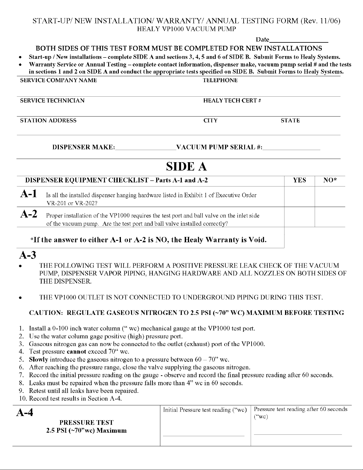
completing the START-UP / NEW INSTALLATION / WARRANTY / ANNUAL TESTING
FORM.
16. TROUBLESHOOTING THE VP1000:
Use extreme care and caution when performing the tests listed below. If 120 VAC is
accidentally applied to the fault or DC terminals, the module will be destroyed.
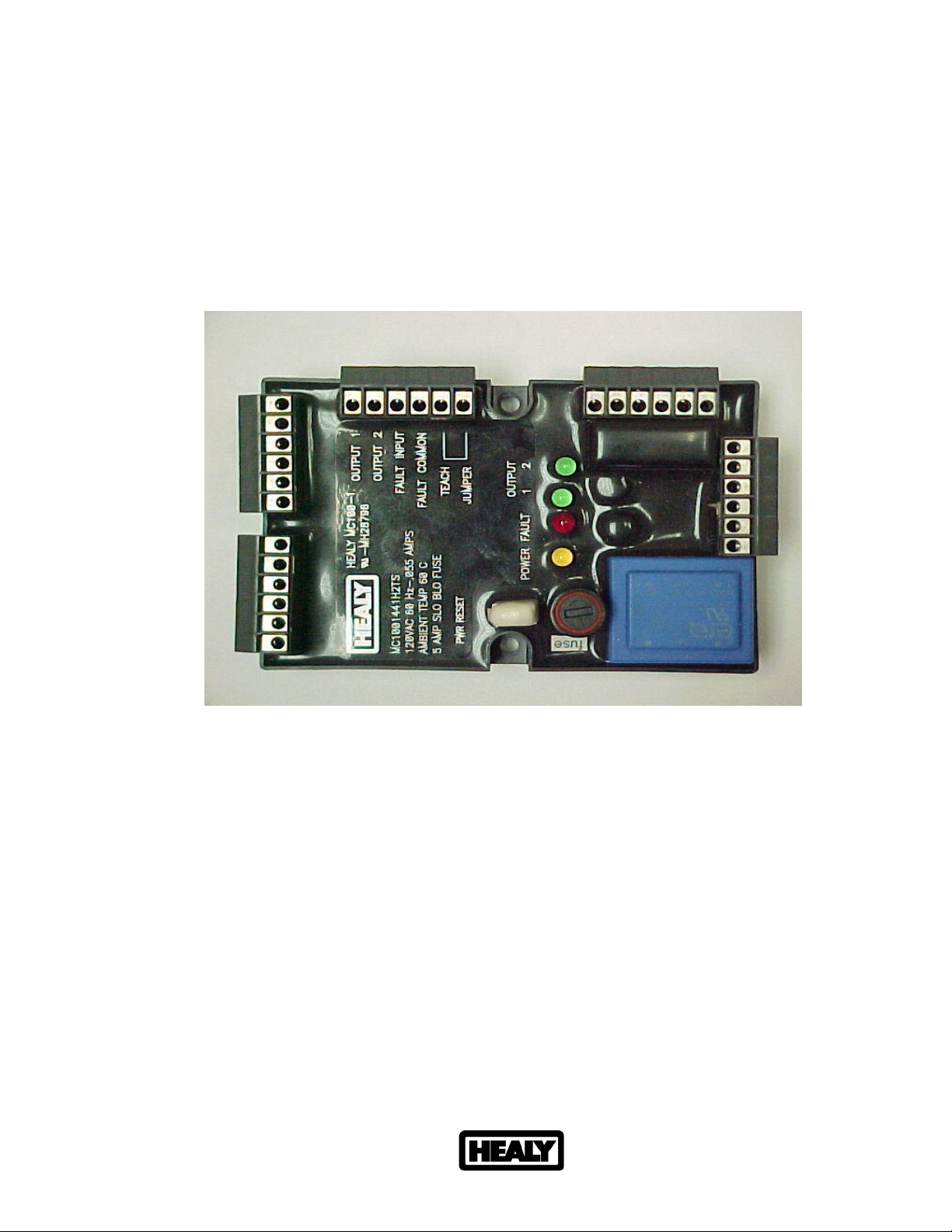
With power applied to the dispenser, but no products authorized, there should be 120
VAC between neutral and 120 VAC on the module terminal strip.
As above, with any product authorized, there should be single speed power applied to
the VP1000. Verify this by checking for 2-3 VDC from OUTPUT 1 (RED WIRE) to
FAULT COMMON (ORANGE WIRE), (or from OUTPUT 2 TO FAULT COMMON) also;
one GREEN LED should be illuminated. With a second product authorized on the
opposite side of the dispenser i.e. one product on each side, the motor should
operate at higher speed and there should be 2-3 VDC on both output 1 and 2 (to fault
common) and both GREEN LED’s should be illuminated.
With the pump running, a fault can be simulated by shorting, with a jumper wire, the
“FAULT INPUT” (purple wire) to FAULT COMMON (orange). This should cause the
motor to shut off, the solenoid valves to lose power and the dispenser to shut down.
Also, as long as the short is maintained, the red LED will be illuminated. Removing
the short will not automatically reset the module. To reset the module, remove the
short, remove power to the dispenser for twenty seconds and restore power. The
module should now be reset and the red led extinguished. This can also be
accomplished by using the power reset (PWR RESET) on the module.
Healy Systems, Inc. Website: http://www.healysystems.com
18 Hampshire Drive Email: [email protected]
Hudson, New Hampshire 03051 USA Telephone: 603.882.2472
ARB Approved Installation, Operation and Maintenance Manual (November 2006) Fax: 603.882.5189
Healy Systems, Inc. – the innovative leader of Stage II vapor recovery equipment
Page 17
ARB Approved IOM – Executive Orders VR-201-B and VR-202-B (Wayne Harmony WayneVac Dispen ser) Page 119
If diagnosing a problem where the LED is already illuminated, a steady light indicates
a low current condition, therefore expect a vane or rotor problem. If the LED is
blinking, that indicates a high current condition and would expect to find a jammed
rotor or vapor line flooded with product. See Start-up / New Installation / Warranty /
Annual Testing Form.
The electronics of the motor will make three attempts to have a successful start of the
motor. If it detects a problem, on the fourth unsuccessful start, it will short the fault
line to signal minus (DC-) and shut down the electronics.
MC100 Interface Module
Healy Systems, Inc. Website: http://www.healysystems.com
18 Hampshire Drive Email: [email protected]
Hudson, New Hampshire 03051 USA Telephone: 603.882.2472
ARB Approved Installation, Operation and Maintenance Manual (November 2006) Fax: 603.882.5189
Healy Systems, Inc. – the innovative leader of Stage II vapor recovery equipment
Page 18
ARB Approved IOM – Executive Orders VR-201-B and VR-202-B (Wayne Harmony WayneVac Dispen ser) Page 120
17. VP1000 VANE & ROTOR SERVICE & REPLACEMENT GUIDE
CAUTION: Disconnect power before beginning serivce
1. The work area must be clean and have sufficient lighting.
2. Disconnect the vapor piping connected to the IN and OUT ports of the VP1000 cover assembly.
3. Remove the four Allen head screws and lock washers that secure the pump cover assembly to the pump
housing and remove the cover carefully. CAUTION: Use a spill cloth when removing the cover, as there
may be some gasoline inside the pump cavity.
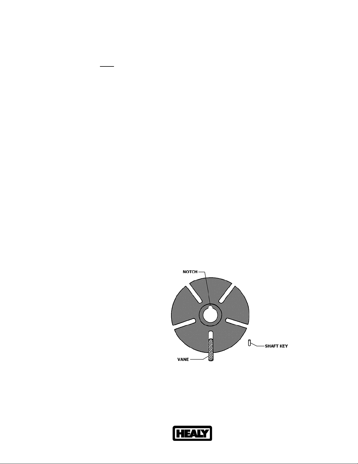
4. Carefully turn the rotor assembly by hand until the shaft key notch is at the 12 o’clock position. (See Figure 1)
5. Remove the rotor, vanes and shaft key from the pump housing. NOTE: Place your hand or a container
under the rotor while removing.
6. Inspect the rotor and vanes for damage or excessive wear such as cracks, chips or breaks. Replace roto r and
vanes if any damage is found. (PN# VP1000VRC)
7. If no visible damage is apparent, the existing rotor and vanes may be reused after thoroughly cleaning with
isopropyl alcohol.
8. Using the isopropyl alcohol with a lint free cloth or rag, thoroughly clean the inside and rear of the pump cavity,
rotor shaft, and the inside of the pump cover assembly. NOTE: Do not use any sharp objects that would
scratch these surfaces.
9. Reposition the shaft (if necessary) so that the shaft key notch is in the 12 o’clock position. Install the cleaned
original or new shaft key onto the shaft.
10. Carefully install the cleaned original or new carbon rotor onto the shaft followed by the cleaned original or new
vanes into the rotor. NOTE: The rotor assembly should slide on the shaft easily, without excessive force.
(Rotor and vanes are reversible)
11. Lightly lubricate and install the inspected original or new O-Ring for the pump housing. NOTE: Do not allow
any lubricant to get inside the pump housing.
12. Install the pump cover using the four Allen head screws and lock washers removed in step 3 and cross tighten.
NOTE: Use caution when sliding the pump cover over the O-Ring seal to prevent cutting or tearing.
13. Re-connect the vapor piping to the IN and OUT ports of the pump cover assembly that was removed in step 2.
14. Re-apply power. Test for normal operation. (See VP1000 Vacuum Performance Test Procedure)
Figure 1
Healy Systems, Inc. Website: http://www.healysystems.com
18 Hampshire Drive Email: [email protected]
Hudson, New Hampshire 03051 USA Telephone: 603.882.2472
ARB Approved Installation, Operation and Maintenance Manual (November 2006) Fax: 603.882.5189
Healy Systems, Inc. – the innovative leader of Stage II vapor recovery equipment
Page 19
ARB Approved IOM – Executive Orders VR-201-B and VR-202-B (Wayne Harmony WayneVac Dispen ser) Page 121
Page 20
ARB Approved IOM – Executive Orders VR-201-B and VR-202-B (Wayne Harmony WayneVac Dispen ser) Page 122
 Loading...