

HealthRider HREX529080 Owner's Manual
Model No. HREX52908.0
Visit our website at
www.healthrider.com
new products, prizes,
fitness tips, and much more!
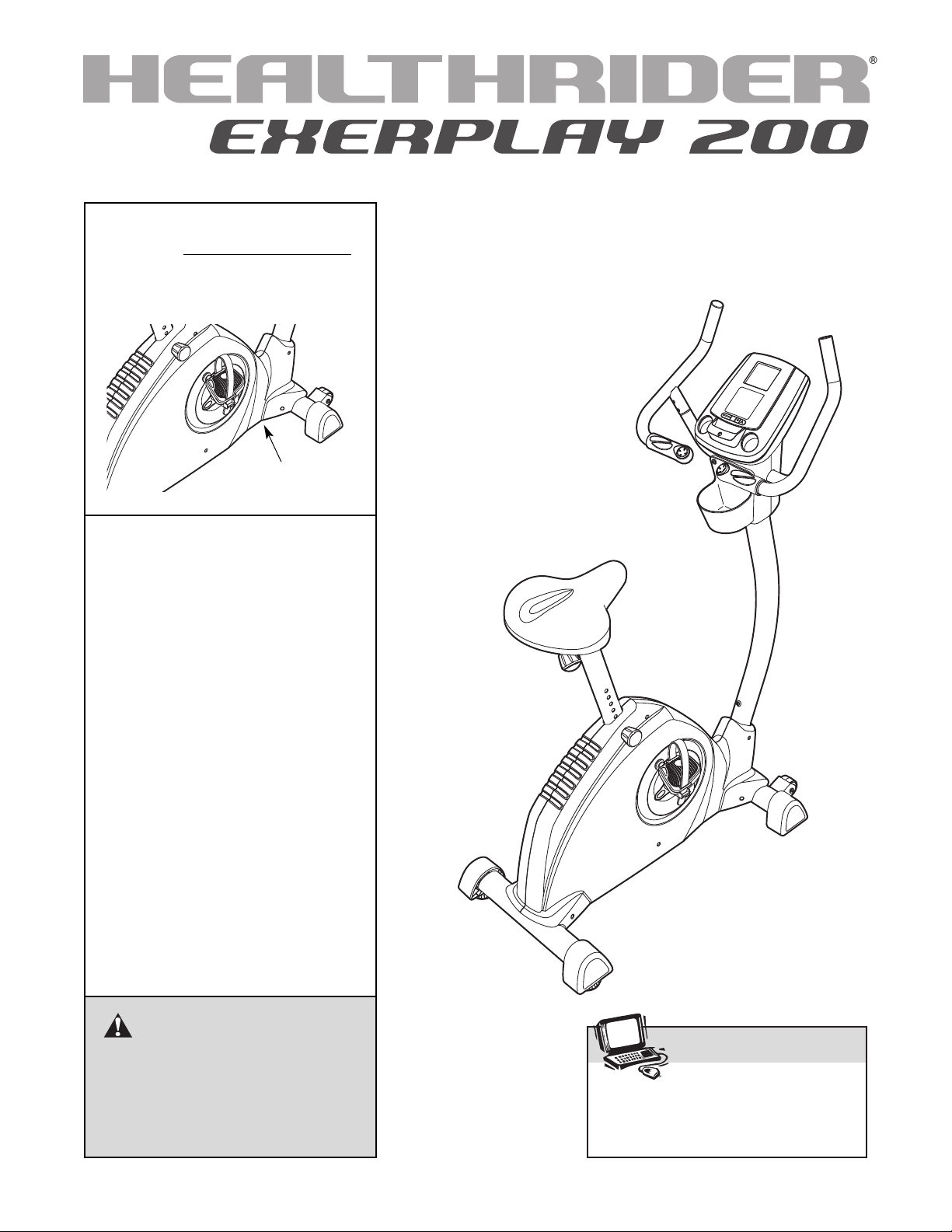
Serial No.
Write the serial number in the
space above for future reference.
Serial Number
Decal (under frame)
QUESTIONS?
As a manufacturer, we are committed to providing complete customer
satisfaction. If you have questions,
or if parts are missing, PLEASE DO
NOT CONTACT THE STORE;
please contact Customer Care.
USER'S MANUAL
IMPORTANT: You must note the
product model number and serial
number (see the drawing above)
before contacting us:
CALL TOLL-FREE:
1-888-922-4222
Mon.–Fri., 6 a.m.–6 p.m. MST
Sat. 8 a.m.–4 p.m. MST
ON THE WEB:
www.healthriderservice.com
CAUTION
Read all precautions and instructions in this manual before using
this equipment. Keep this manual
for future reference.
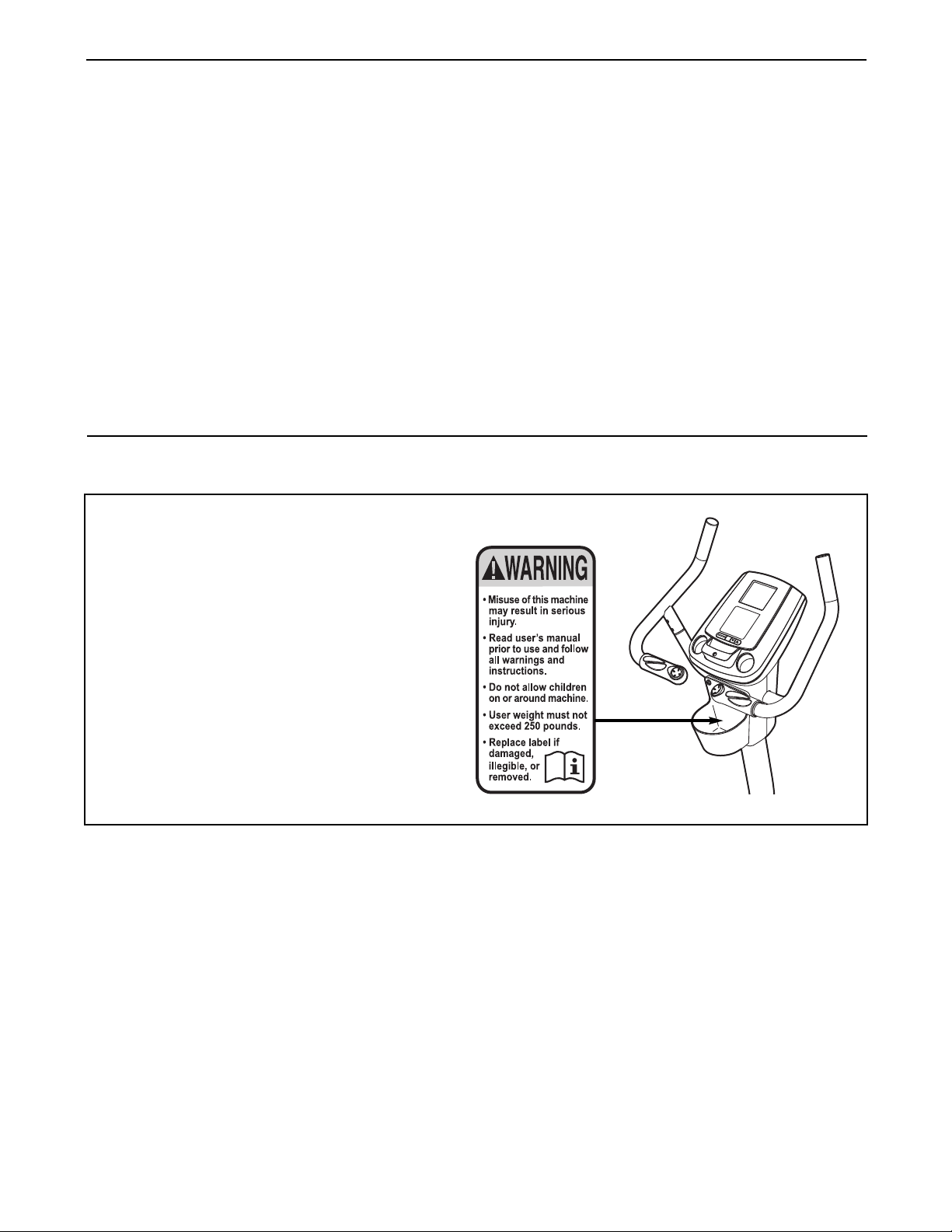
TABLE OF CONTENTS
ARNING DECAL PLACEMENT . . . . . . . . . . . . . . . . . . . . . . . . . . . . . . . . . . . . . . . . . . . . . . . . . . . . . . . . . . . . . .2
W
IMPORTANT PRECAUTIONS . . . . . . . . . . . . . . . . . . . . . . . . . . . . . . . . . . . . . . . . . . . . . . . . . . . . . . . . . . . . . . . .3
BEFORE YOU BEGIN . . . . . . . . . . . . . . . . . . . . . . . . . . . . . . . . . . . . . . . . . . . . . . . . . . . . . . . . . . . . . . . . . . . . . .4
ASSEMBLY . . . . . . . . . . . . . . . . . . . . . . . . . . . . . . . . . . . . . . . . . . . . . . . . . . . . . . . . . . . . . . . . . . . . . . . . . . . . . . .5
OW TO USE THE EXERCISE CYCLE . . . . . . . . . . . . . . . . . . . . . . . . . . . . . . . . . . . . . . . . . . . . . . . . . . . . . . .13
H
MAINTENANCE AND TROUBLESHOOTING . . . . . . . . . . . . . . . . . . . . . . . . . . . . . . . . . . . . . . . . . . . . . . . . . . .23
EXERCISE GUIDELINES . . . . . . . . . . . . . . . . . . . . . . . . . . . . . . . . . . . . . . . . . . . . . . . . . . . . . . . . . . . . . . . . . . .24
PART LIST . . . . . . . . . . . . . . . . . . . . . . . . . . . . . . . . . . . . . . . . . . . . . . . . . . . . . . . . . . . . . . . . . . . . . . . . . . . . . .26
EXPLODED DRAWING . . . . . . . . . . . . . . . . . . . . . . . . . . . . . . . . . . . . . . . . . . . . . . . . . . . . . . . . . . . . . . . . . . . .27
ORDERING REPLACEMENT PARTS . . . . . . . . . . . . . . . . . . . . . . . . . . . . . . . . . . . . . . . . . . . . . . . . . .Back Cover
LIMITED WARRANTY . . . . . . . . . . . . . . . . . . . . . . . . . . . . . . . . . . . . . . . . . . . . . . . . . . . . . . . . . . . . . .Back Cover
WARNING DECAL PLACEMENT
This drawing shows the location(s) of the
warning decal(s). If a decal is missing
or illegible, call the telephone number
on the front cover of this manual and
request a free replacement decal.
Apply the decal in the location shown.
Note: The decal(s) may not be shown at
actual size.
HEALTHRIDER is a registered trademark of ICON IP, Inc.
2

IMPORTANT PRECAUTIONS
WARNING: To reduce the risk of serious injury, read all important precautions and
instructions in this manual and all warnings on your exercise cycle before using your exercise
cycle. ICON assumes no responsibility for personal injury or property damage sustained by or
through the use of this product.
1. Before beginning any exercise program, consult your physician. This is especially important for persons over the age of 35 or persons with pre-existing health problems.
2. Use the exercise cycle only as described in
this manual.
3. It is the responsibility of the owner to ensure
that all users of the exercise cycle are adequately informed of all precautions.
4. The exercise cycle is intended for home use
only. Do not use the exercise cycle in a commercial, rental, or institutional setting.
5. Keep the exercise cycle indoors, away from
moisture and dust. Place the exercise cycle
on a level surface, with a mat beneath it to
protect the floor or carpet. Make sure that
there is enough clearance around the exercise cycle to mount, dismount, and use it.
6. Inspect and properly tighten all parts regularly. Replace any worn parts immediately.
7. Keep children under the age of 12 and pets
away from the exercise cycle at all times.
8. Wear appropriate clothes while exercising;
do not wear loose clothes that could become
caught on the exercise cycle. Always wear
athletic shoes for foot protection.
9. The exercise cycle should not be used by
persons weighing more than 250 lbs.
(113 kg).
10. The pulse sensor is not a medical device.
Various factors, including the user's movement, may affect the accuracy of heart rate
readings. The pulse sensor is intended only
as an exercise aid in determining heart rate
trends in general.
11. Always keep your back straight while using
the exercise cycle; do not arch your back.
12. If you feel pain or dizziness while exercising,
stop immediately and cool down.
3
BEFORE YOU BEGIN
ongratulations for selecting the revolutionary
C
HEALTHRIDER
Cycling is one of the most effective exercises for
increasing cardiovascular fitness, building endurance,
nd toning the entire body. The EXERPLAY 200 exer-
a
cise cycle offers an impressive array of features,
including motivational interactive games, designed to
let you enjoy this healthful exercise in the comfort and
convenience of your home.
For your benefit, read this manual carefully before
you use the exercise cycle. If you have questions
after reading this manual, please see the front cover
Handgrip Pulse Sensor
Game Controller
®
EXERPLAY 200 exercise cycle.
f this manual. To help us assist you, note the product
o
model number and serial number before contacting
us. The model number and the location of the serial
number decal are shown on the front cover of this
anual.
m
To avoid a registration fee for any service needed
under warranty, you must register the exercise
cycle at www.healthrider.com/registration.
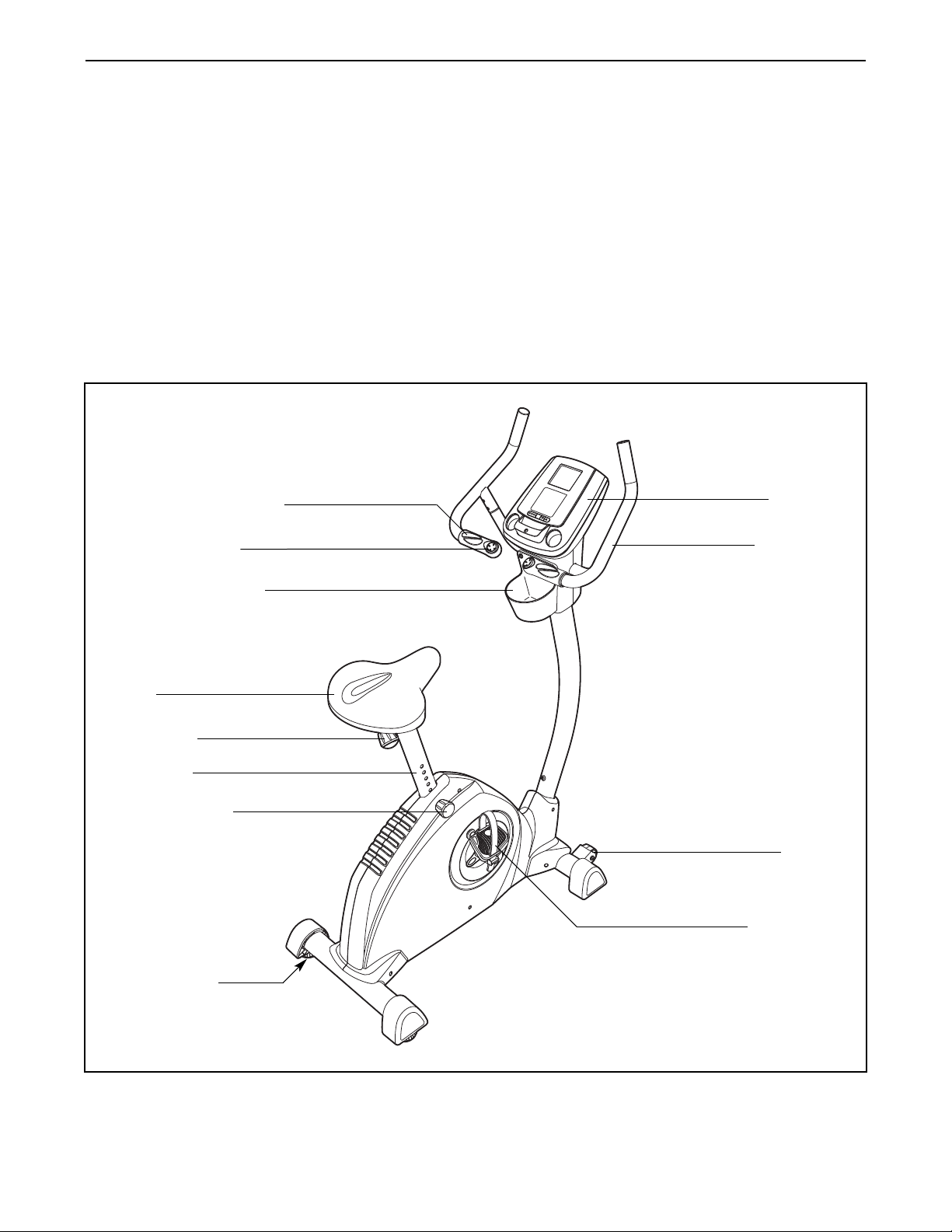
Before reading further, please familiarize yourself with
the parts that are labeled in the drawing below.
Console
Handlebar
Water Bottle Holder*
Seat
Seat Knob
Seat Post
Seat Post Knob
Leveling Foot
Wheel
Pedal/Strap
*Water bottle is not included
4
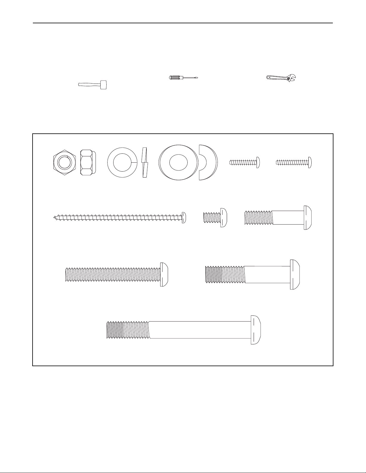
M4 x 19mm
Screw (33)–2
M10 x 85mm Patch
Screw (56)–4
M10 Split
Washer (63)–3
M10 x 50mm Patch
Screw (46)–3
M4 x 16mm
Screw (58)–6
M6 x 10mm
Button Screw
(60)–2
M8 Locknut
(57)–6
M4 x 76mm Screw
(66)–2
M8 x 35mm Button
Bolt (64)–4
M8 x 56mm Button
Screw (61)–2
M10 Curved
Washer (68)–4
ASSEMBLY
To hire an authorized service technician to assemble the exercise cycle, call 1-800-445-2480.
Assembly requires two persons. Place all parts of the exercise cycle in a cleared area and remove the pack-
ing materials. Do not dispose of the packing materials until assembly is completed. In addition to the included
tools, assembly requires a Phillips screwdriver , an adjustable wrench , and
rubber mallet .
a
As you assemble the exercise cycle, use the drawings below to identify small parts. The number in parentheses
below each drawing is the key number of the part, from the PART LIST near the end of this manual. The number
following the parentheses is the quantity needed for assembly. Note: Some small parts may have been pre-
assembled. If a part is not in the hardware kit, check to see if it has been preassembled.
5
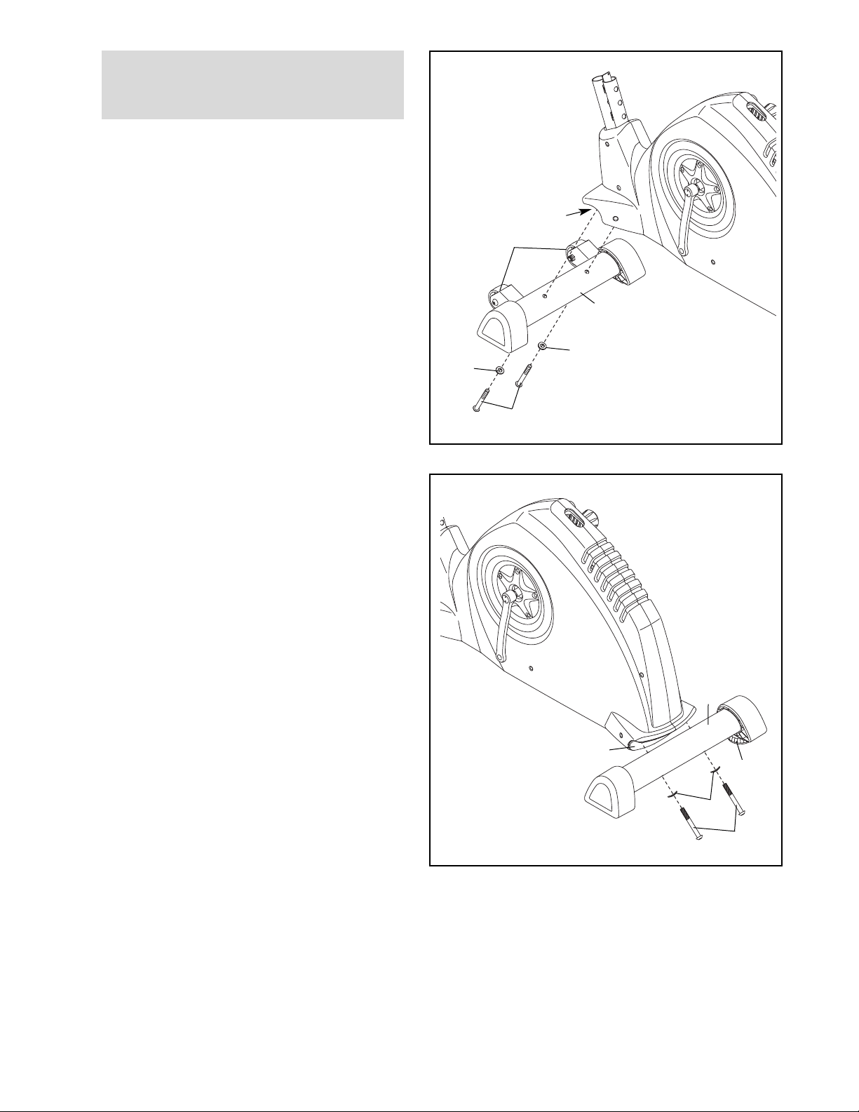
1.
To make assembly easier, read the
information on page 5 before you begin
ssembling the exercise cycle.
a
Identify the Front Stabilizer (2), which has
Wheels (17) attached. Attach the Front
tabilizer to the Frame (1) with two M10 x
S
85mm Patch Screws (56) and two M10 Curved
Washers (68).
1
1
17
2
68
68
56
2. Attach the Rear Stabilizer (3) to the Frame (1)
with two M10 x 85mm Patch Screws (56) and
two M10 Curved Washers (68).
2
3
1
29
68
56
6
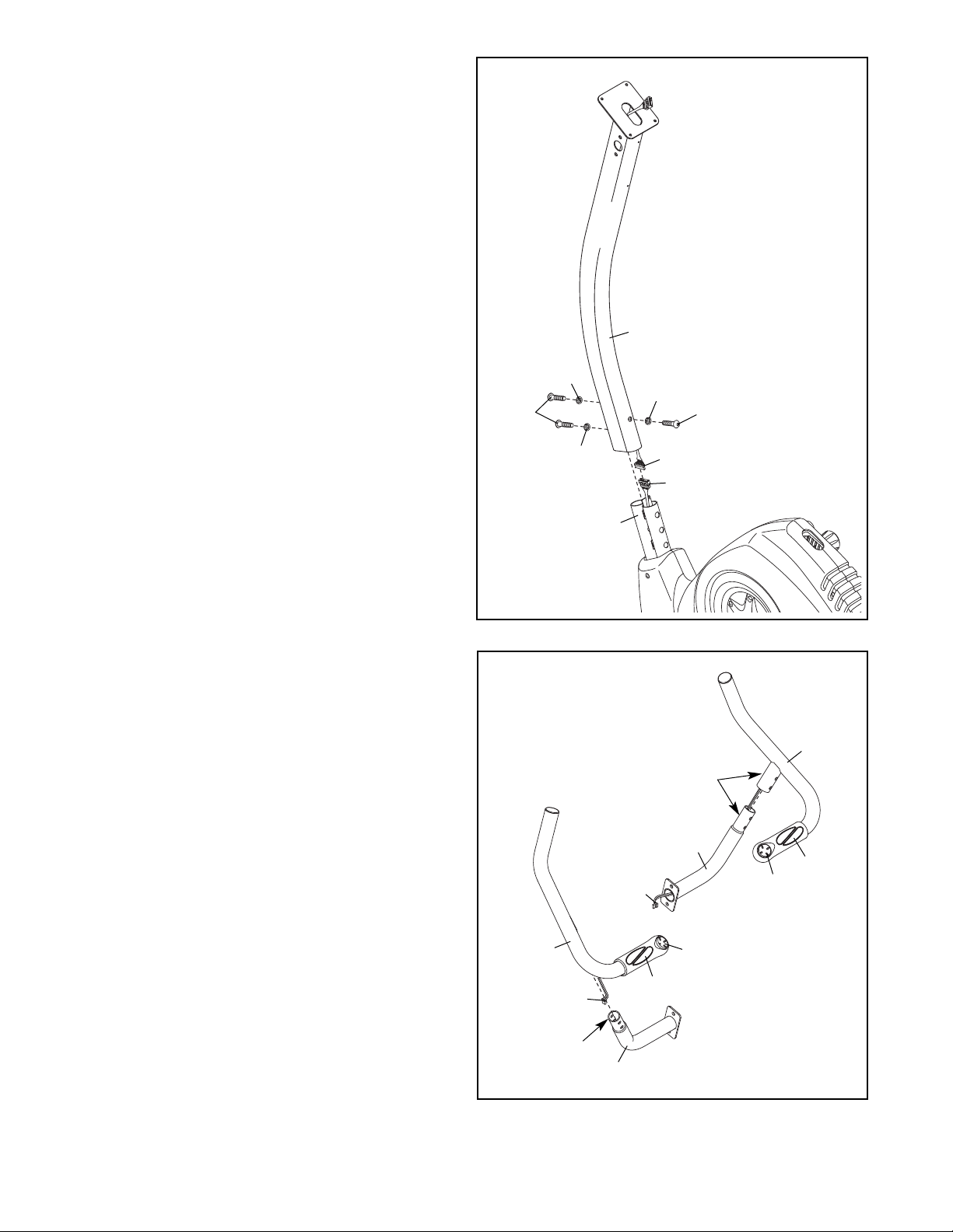
3. Tip: Avoid pinching the wires during this
tep.
s
While another person holds the Upright (6) near
the Frame (1), connect the Upper Wire Harness
(55) to the Lower Wire Harness (51). Next, pull
the excess Upper Wire Harness out of the top
of the Upright.
3
Slide the Upright (6) onto the Frame (1). Attach
the Upright with three M10 x 50mm Patch
Screws (46) and three M10 Split Washers (63).
Tighten the two Patch Screws in the front of
the Upright first, and then tighten the third
Patch Screw.
4. Identify the Right and Left Handlebars (35, 36),
which are marked with “Right” and “Left” stickers.
Avoid pinching
the wires
6
63
63
46
63
1
4
46
55
51
Orient the two Handlebar Posts (7) and the
Right and Left Handlebars (35, 36) as shown.
Make sure that the Game Controllers (10),
Grips (30), and hexagonal holes are in the
indicated locations.
Locate the Right and Left Controller Wires (54,
67) in the Right and Left Handlebars (35, 36).
Then, insert the Right and Left Controller Wires
through the Handlebar Posts (7).
36
Hexagonal
Holes
67
54
7
35
Hexagonal
Holes
7
30
10
10
30
7
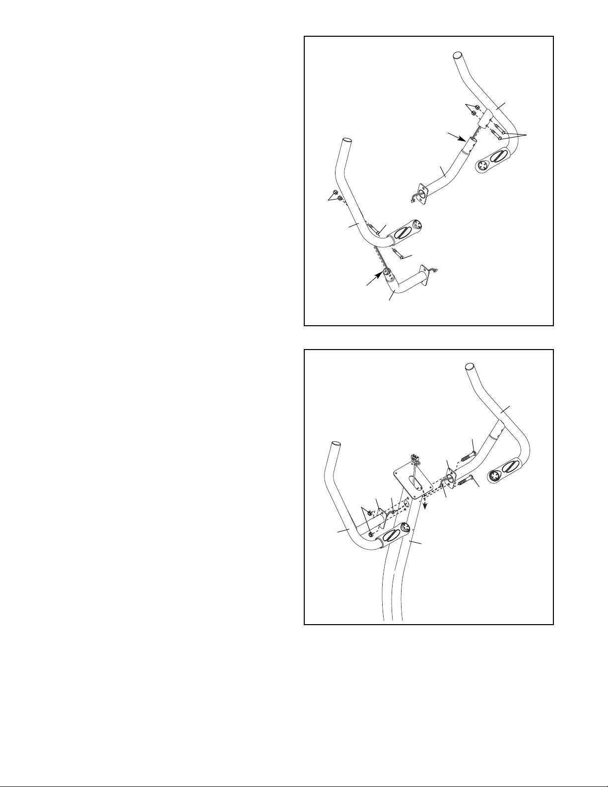
5. Tip: Avoid pinching the wires during this
step.
Attach each Handlebar (35, 36) to a Handlebar
Post (7) with two M8 x 35mm Button Bolts (64)
nd two M8 Locknuts (57). Make sure that the
a
Locknuts are in the hexagonal holes.
5
57
36
Hexagonal
Holes
Hexagonal
64
7
H
64
oles
57
7
Avoid pinching
35
64
the wires
6. Have another person hold the Right and Left
Handlebars (35, 36) near the Upright (6). Insert
the Right and Left Controller Wires (54, 67) into
the holes in the Upright and pull them upward
out of the top of the Upright.
Tip: Avoid pinching the wires during this
step. Attach the Handlebar Posts (7) to the
Upright (6) with two M8 x 56mm Button Screws
(61) and two M8 Locknuts (57).
6
Avoid pinching
36
the wires
57
61
7
67
7
54
6
61
35
8
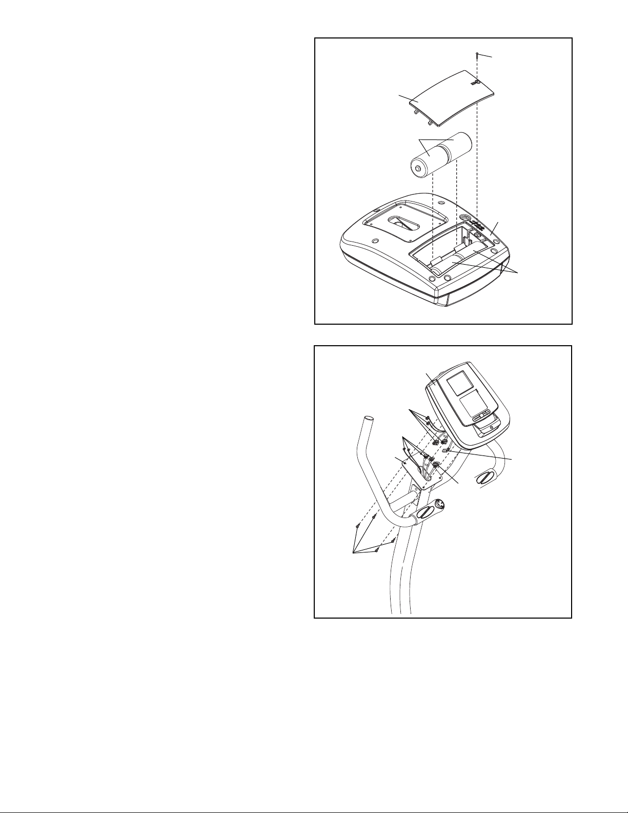
7. The Console (9) can use four 1.5V “D” batteries
(not included); alkaline batteries are recommended. IMPORTANT: If the Console has
een exposed to cold temperatures, allow it
b
to warm to room temperature before insert-
ng batteries. Otherwise, you may damage
i
the console displays or other electronic
components. Remove the screw, remove the
battery cover, insert the batteries into the battery compartments, and reattach the battery
cover. Make sure to orient the batteries as
shown by the diagrams inside the battery
compartments.
7
crew
S
Battery
Cover
Batteries
To purchase an optional AC adapter, contact
the store where you purchased this product
or call the telephone number on the cover of
this manual. To avoid damaging the console,
use only a manufacturer-supplied AC
adapter. Plug one end of the AC adapter into
the jack on the console; plug the other end into
an outlet installed in accordance with all local
codes and ordinances.
8. While another person holds the Console (9)
near the Upright (6), connect the console wire
harnesses to the Controller/Pulse Wires (54, 67)
and to the Upper Wire Harness (55); make
sure to connect the console wire that has a
tag to the Controller/Pulse wire that has a
tag. Insert the excess wire downward into the
Upright.
Tip: Avoid pinching the wires during this
step. Attach the Console (9) to the Upright (6)
with four M4 x 16mm Screws (58).
9
Batteries
8
9
Console Wire
Harnesses
54,67
6
55
Console
Wire
Harness
58
Avoid pinching
the wires
9
 Loading...