

www.iconeurope.com
Visit our website at
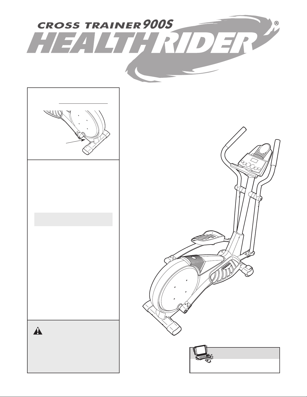
Class HC Fitness Product
Model No. HREVEL36040
Serial No.
Serial
Number
Decal
QUESTIONS?
As a manufacturer, we are committed to providing complete
customer satisfaction. If you have
questions, or if there are missing
or damaged parts, please call:
08457 089 009
USERʼS MANUAL
Or write:
ICON Health & Fitness, Ltd.
Customer Service Department
Unit 4
Revie Road Industrial Estate
Revie Road
Beeston
Leeds, LS118JG
UK
email: csuk@iconeurope.com
CAUTION
Read all precautions and instructions in this manual before using
this equipment. Keep this manual for future reference.

TABLE OF CONTENTS
IMPORTANT PRECAUTIONS . . . . . . . . . . . . . . . . . . . . . . . . . . . . . . . . . . . . . . . . . . . . . . . . . . . . . . . . . . . . . . . . .2
EFORE YOU BEGIN . . . . . . . . . . . . . . . . . . . . . . . . . . . . . . . . . . . . . . . . . . . . . . . . . . . . . . . . . . . . . . . . . . . . . . .3
B
ASSEMBLY . . . . . . . . . . . . . . . . . . . . . . . . . . . . . . . . . . . . . . . . . . . . . . . . . . . . . . . . . . . . . . . . . . . . . . . . . . . . . . .4
HOW TO USE THE CHEST PULSE SENSOR . . . . . . . . . . . . . . . . . . . . . . . . . . . . . . . . . . . . . . . . . . . . . . . . . . . .8
HOW TO OPERATE THE ELLIPTICAL CROSSTRAINER . . . . . . . . . . . . . . . . . . . . . . . . . . . . . . . . . . . . . . . . . .10
AINTENANCE AND TROUBLESHOOTING . . . . . . . . . . . . . . . . . . . . . . . . . . . . . . . . . . . . . . . . . . . . . . . . . . . .23
M
CONDITIONING GUIDELINES . . . . . . . . . . . . . . . . . . . . . . . . . . . . . . . . . . . . . . . . . . . . . . . . . . . . . . . . . . . . . . .24
PART LIST . . . . . . . . . . . . . . . . . . . . . . . . . . . . . . . . . . . . . . . . . . . . . . . . . . . . . . . . . . . . . . . . . . . . . . . . . . . . . . .26
EXPLODED DRAWING . . . . . . . . . . . . . . . . . . . . . . . . . . . . . . . . . . . . . . . . . . . . . . . . . . . . . . . . . . . . . . . . . . . . .27
ORDERING REPLACEMENT PARTS . . . . . . . . . . . . . . . . . . . . . . . . . . . . . . . . . . . . . . . . . . . . . . . . . .Back Cover
IMPORTANT PRECAUTIONS
WARNING: To reduce the risk of serious injury, read the following important precau-
tions before using the elliptical crosstrainer.
1. Read all instructions in this manual before
using the elliptical crosstrainer.
2. It is the responsibility of the owner to ensure
that all users of the elliptical crosstrainer
are adequately informed of all precautions.
3. Place the elliptical crosstrainer on a level
surface, with a mat beneath it to protect the
floor or carpet. Keep the elliptical crosstrainer indoors, away from moisture and dust.
4. Inspect and properly tighten all parts regularly. Replace any worn parts immediately.
5. Keep children under 12 and pets away from
the elliptical crosstrainer at all times.
6. The elliptical crosstrainer should not be used
by persons weighing more than 115 kg (250
lbs).
7. Wear appropriate exercise clothes when
using the elliptical crosstrainer. Always wear
athletic shoes for foot protection.
8. Always hold the handgrip pulse sensor or the
handlebars when mounting, dismounting, or
using the elliptical crosstrainer.
9. The pulse sensors are not medical devices.
Various factors may affect the accuracy of
heart rate readings. The pulse sensors are
intended only as exercise aids in determining heart rate trends in general.
10. Keep your back straight when using the elliptical crosstrainer; do not arch your back.
11. If you feel pain or dizziness at any time
whilst exercising, stop immediately and
begin cooling down.
12. When you stop exercising, allow the pedals
to slowly come to a stop.
13. The elliptical crosstrainer is intended for
home use only. Do not use the elliptical
crosstrainer in a commercial, rental, or institutional setting.
WARNING: Before beginning this or any exercise program, consult your physician.
This is especially important for persons over the age of 35 or persons with pre-existing health problems. Read all instructions before using. ICON assumes no responsibility for personal injury or
property damage sustained by or through the use of this product.
2
BEFORE YOU BEGIN
ROSS
C
®
Congratulations for selecting the new HealthRider
ROSS TRAINER 900S. The HealthRider
C
TRAINER 900S is an incredibly smooth exerciser that
moves your feet in a natural elliptical path, minimising
the impact on your knees and ankles. And the unique
CROSS TRAINER 900S features adjustable resistance and a state-of-the-art console to help you get the
most from your exercise. Welcome to a whole new
world of natural, elliptical-motion exercise from
HealthRider.
For your benefit, read this manual carefully before
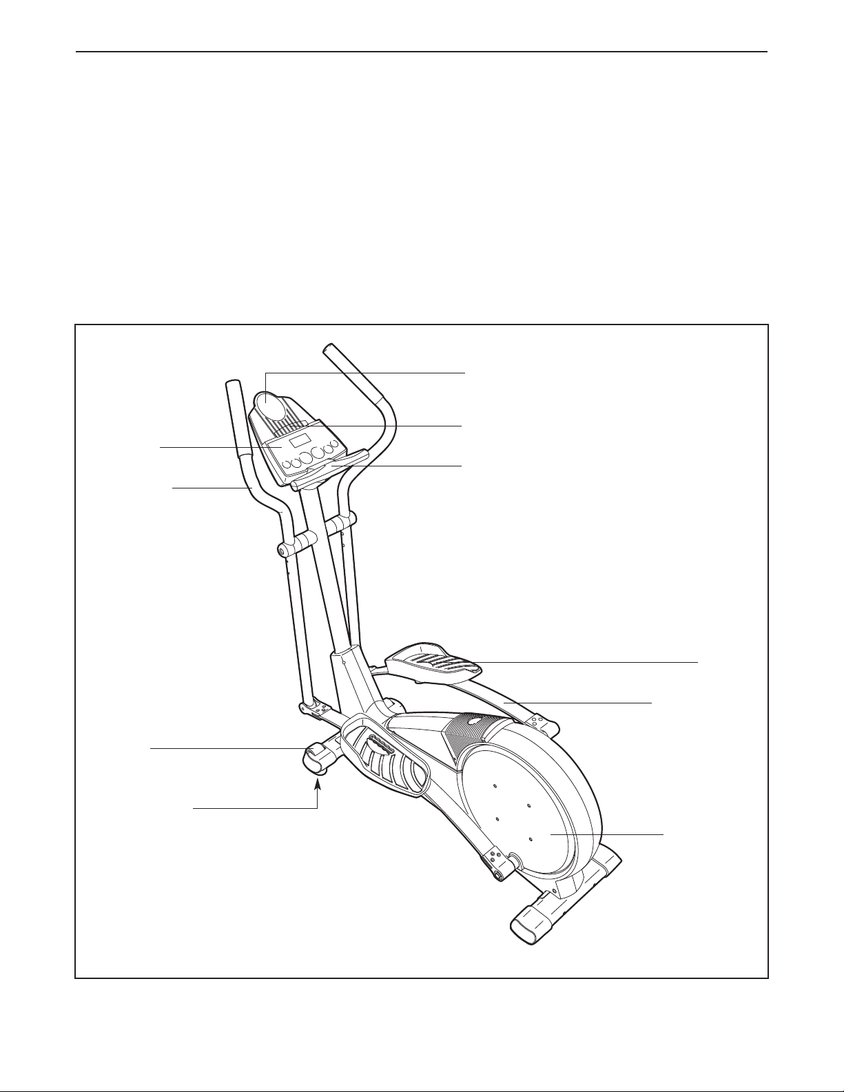
Console
Handlebar
®
you use the elliptical crosstrainer. If you have ques-
ions after reading this manual, please call our
t
Customer Service Department at 08457 089 009. To
help us assist you, please note the product model
number and serial number before calling. The model
number is HREVEL36040. The serial number can be
found on a decal attached to the elliptical crosstrainer
(see the front cover of this manual for the location of
the decal).
Before reading further, please familiarise yourself with
the parts that are labelled in the drawing below.
Water Bottle Holder*
Bookrack
Handgrip Pulse Sensor
FRONT
Wheel
Levelling Foot
Pedal
Pedal Spring
BACK
Pedal Disk
LEFT SIDE
*No water bottle
is included
3
ASSEMBLY
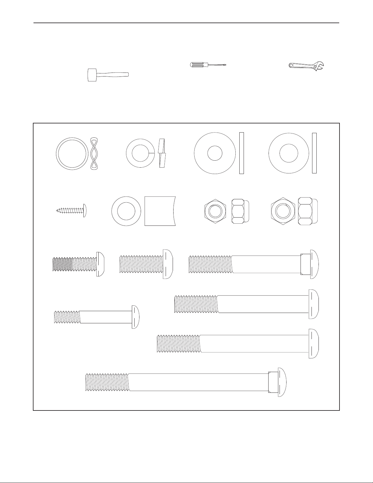
M10 x 112mm Carriage Bolt (34)–4
Adjustment Bolt (20)–2
M10 x 88mm Button Bolt (63)–1
M10 x 78mm Button Bolt (27)–2
M4 x 16mm
Screw (66)–2
M10 x 27mm
Screw (71)–3
M10
Washer (38)–6
M10 Split
Washer (70)–6
M10 Nylon
Locknut (29)–6
Frame Spacer (83)–1
M8 x 45mm Button Bolt (50)–4
M8 Nylon
Locknut (46)–4
Wave Washer
(94)–2
M8.5
Washer (53)–2
M8 x 25mm Patch
Screw (22)–2
Assembly requires two persons. Place all parts of the elliptical crosstrainer in a cleared area and remove the
packing materials. Do not dispose of the packing materials until assembly is completed. Assembly requires the
included hex keys and your own phillips screwdriver , adjustable spanner ,
nd rubber mallet .
a
As you assemble the elliptical crosstrainer, use the drawings below to identify the small parts needed for assembly. The number in parenthesis below each drawing is the key number of the part, from the PART LIST on page
26. The number following the parenthesis is the quantity needed for assembly. Note: Some parts may have
been pre-assembled. If a part is not in the parts bag, check to see if it has been pre-assembled.
4
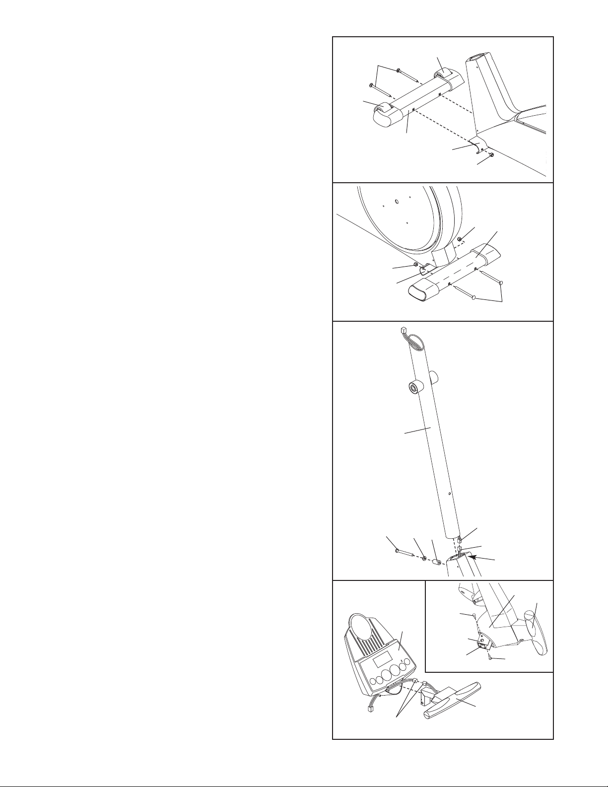
1. Identify the Front Stabiliser (3), which has Wheels (32)
attached to it. Whilst another person lifts the front of
the Frame (1), attach the Front Stabiliser to the Frame
ith two M10 x 112mm Carriage Bolts (34) and two
w
M10 Nylon Locknuts (29). Make sure that the Front
tabiliser is turned so the Wheels are not touching
S
the floor.
1
4
3
32
32
3
1
29
2. Whilst another person lifts the back of the Frame (1),
attach the Rear Stabiliser (4) to the Frame with two
M10 x 112mm Carriage Bolts (34) and two M10 Nylon
Locknuts (29).
3. Whilst another person holds the Upright (2) in the
position shown, connect the Upper Wire Harness (86)
to the Lower Wire Harness (87). Carefully pull the
upper end of the Upper Wire Harness to remove
any slack. Whilst holding the upper end of the
Upper Wire Harness, insert the Upright into the
Frame (1). Do not pinch the Wire Harnesses.
Slide an M10 Split Washer (70) and a Frame Spacer
(83) onto the M10 x 88mm Button Bolt (63), and insert
the Button Bolt into the Frame (1) and the Upright (2).
Make sure that the concave end of the Frame
Spacer is turned toward the Frame. Do not tighten
the Button Bolt yet.
2
29
4
29
1
34
3
Make sure the
Wire Harnesses
(86, 87) do not
get pinched and
damaged during
this step.
2
4. Connect the wire harness on the Handgrip Pulse
Sensor (81) to the indicated wire harness on the
Console (5). Insert both wire harnesses into the opening in the bottom of the Console.
Refer to the inset drawing. Insert the metal tube on the
Handgrip Pulse Sensor (81) into the metal bracket
inside the Console (5) as shown. Be careful not to
pinch the wire harnesses. Align the holes in the
metal tube with the holes in the metal bracket, and
tighten two M4 x 16mm Screws (66) into the indicated
holes.
63
4
Wire Harnesses
5
70
83
66
Bracket
Tube
86
81
87
1
5
81
66
5
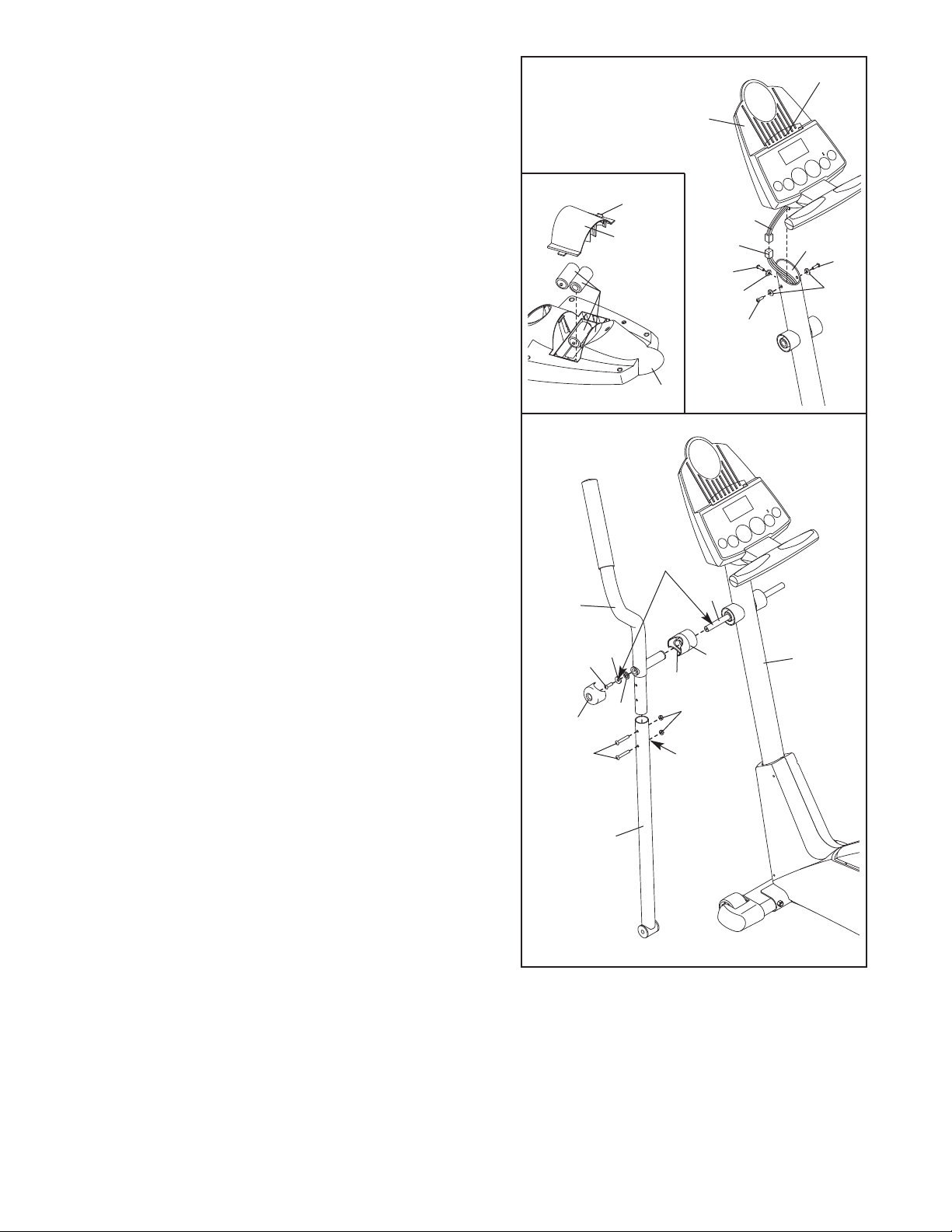
5. The Console (5) requires four 1.5V “D” batteries; alkaline batteries are recommended. Refer to the inset
drawing. Press the tab on the battery cover, and lift off
he battery cover. Insert four batteries into the battery
t
compartment. Make sure that the batteries are
urned as shown by the diagram in the battery
t
compartment. Reattach the battery cover.
Whilst another person holds the Console (5) in the
position shown, connect the wire harness on the
Console to the Upper Wire Harness (86). Insert the
excess wire harness into the Upright (2). Next, attach
the Console to the Upright with three M10 x 27mm
Screws (71) and three M10 Split Washers (70). Be
careful to avoid pinching the wire harnesses.
Snap the bookrack onto the Console (5) in the indicated
location.
5
5
Tab
Battery
Cover
Batteries
Wire
Harness
86
71
70
71
5
ookrack
B
2
71
70
6. Identify the Left Handlebar (9), which is marked with a
sticker. Insert the Left Handlebar into one of the
Handlebar Legs (79); make sure that the Handlebar
Leg is turned so the hexagonal holes are on the
indicated side. Attach the Left Handlebar to the
Handlebar Leg with two M8 x 45mm Button Bolts (50)
and two M8 Nylon Locknuts (46). Make sure that the
Nylon Locknuts are inside of the hexagonal holes.
Do not tighten the Button Bolts yet.
Apply a generous amount of the included grease to the
Pivot Axle (92) and to the two M8.5 Washers (53). Next,
insert the Pivot Axle into the Upright (2) and centre it.
Reapply grease to both ends of the Pivot Axle.
Slide a Handlebar Spacer (25) onto the short tube on
the Left Handlebar (9), and rotate the Handlebar Spacer
so the small arrow is pointing toward the floor. Next,
slide the Left Handlebar onto the left end of the Pivot
Axle (92). Finger tighten an M8 x 25mm Patch Screw
(22) with an M8.5 Washer (53) and a Wave Washer (94)
into the end of the Pivot Axle. Then, press the small tabs
on a Handlebar Cap (23) into the Handlebar Spacer.
Assemble the Right Handlebar (not shown) and the other
Handlebar Leg (not shown) in the same way.
6
Grease
Arrow
46
Hexagonal
Holes
92
25
2
23
9
22
50
53
94
79
Tighten both M8 x 25mm Patch Screws (22) at the same
time.
6
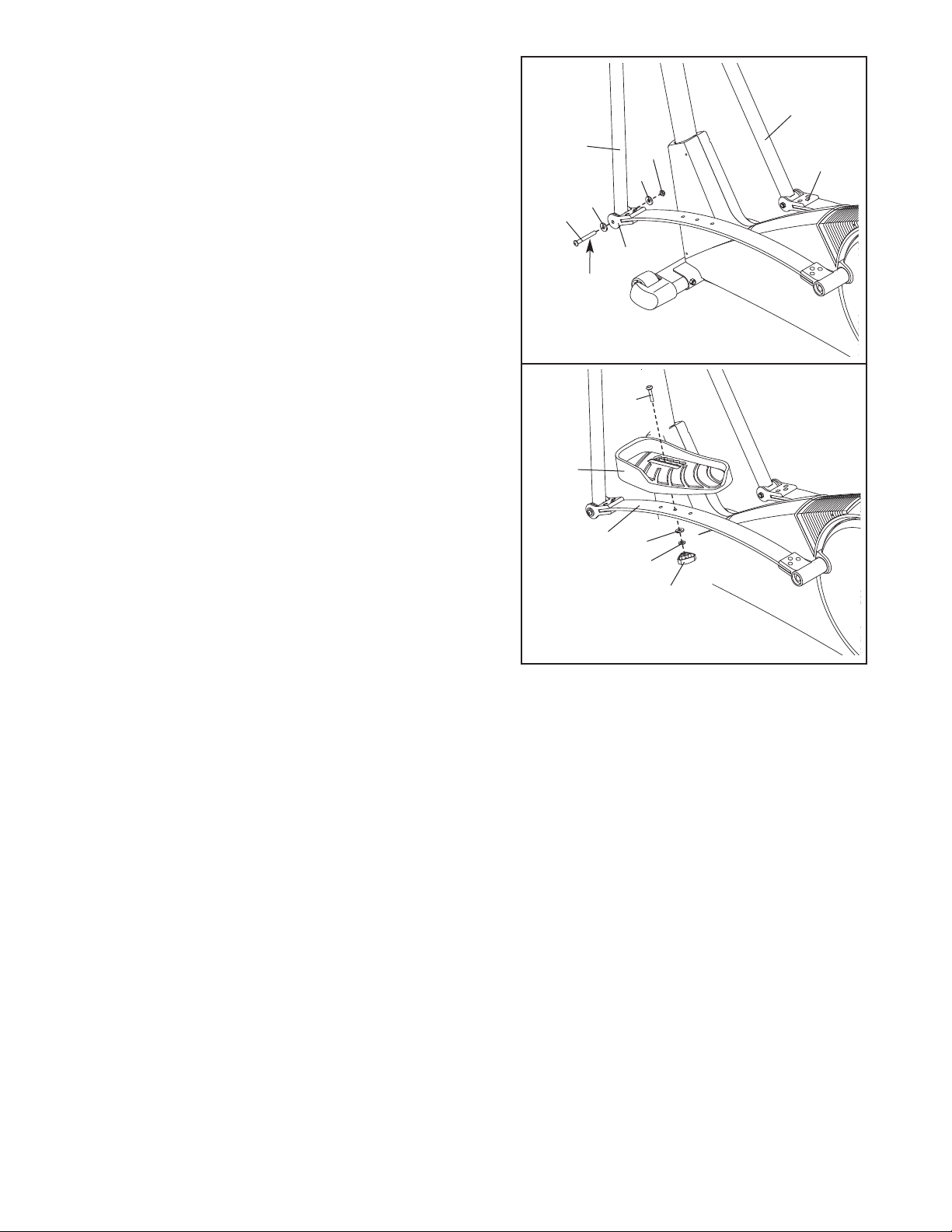
7. Hold the lower end of the left Handlebar Leg (79) inside
of the left Front Spring Bracket (17). Apply a generous
amount of grease to an M10 x 78mm Button Bolt (27).
ttach the left Handlebar Leg to the left Front Spring
A
Bracket (17) with the Button Bolt, two M10 Washers
38), and an M10 Nylon Locknut (29). Do not over-
(
tighten the Nylon Locknut; the left Handlebar Leg
must be able to pivot freely.
Attach the right Handlebar Leg (79) to the right Front
Spring Bracket (17) in the same way.
Refer to step 6. Tighten the M8 x 45mm Button Bolts
(50) in the Handlebar Legs (79). Refer to step 3.
Tighten the M10 x 88mm Button Bolt (63).
7
79
7
2
Grease
38
17
79
29
8
3
17
8. Identify the Left Pedal (13). Attach the Left Pedal to the
left Pedal Spring (14) with an Adjustment Bolt (20), an
M10 Washer (38), an M10 Split Washer (70), and an
Adjustment Knob (15) as shown. Note: The Left Pedal
can be attached in several positions using the five positions in the Left Pedal and the three holes in the Pedal
Spring (see HOW TO ADJUST THE PEDALS on page
10).
Attach the Right Pedal (not shown) in the same way.
Make sure that both Pedals are in the same hole and in
the same pedal position.
9. Make sure that all parts of the elliptical crosstrainer are properly tightened. Note: Some hardware may
be left over after assembly is completed. To protect the floor or carpet from damage, place a mat under the
elliptical crosstrainer.
8
20
13
14
38
70
15
7

HOW TO USE THE CHEST PULSE SENSOR
HOW TO PUT ON THE CHEST PULSE SENSOR
The chest pulse sensor consists of two components:
the chest strap and the sensor unit. Follow the steps
below to put on the chest pulse sensor.
Chest Strap
Tab
Sensor Unit
See the inset drawing above. Insert the tab on
1
one end of the chest strap through one end of the
sensor unit. Press the end of the sensor unit
under the buckle on the chest strap.
Wrap the
2
chest pulse
sensor
around
your chest.
Attach the
free end of
the chest
strap to the
sensor unit as described above. Adjust the length
of the chest strap, if necessary. The chest pulse
sensor should be under your clothes, against
your skin, and as high under the pectoral muscles or breasts as is comfortable. Make sure that
the logo is right-side-up and facing forward.
Pull the
3
sensor unit
away from
your body
a few inches and
locate the
two electrode areas on the inner side. Using a saline
solution such as saliva or contact lens solution,
wet both electrode areas. Return the sensor unit
to a position against your chest.
Buckle
Logo
Electrode Areas
Sensor
Unit
CHEST PULSE SENSOR TROUBLESHOOTING
If the chest pulse sensor does not function properly, or if the displayed heart rate is excessively high
or low, try the troubleshooting steps below.
• Make sure that you are wearing the chest pulse sensor as described at the left. If the chest pulse sensor
does not function when positioned as described,
move it slightly lower or higher on your chest.
• Each time you use the chest pulse sensor, use
saline solution such as saliva or contact lens solution to wet the two electrode areas on the sensor
unit (see the drawing below). If heart rate readings
do not appear until you begin perspiring, re-wet the
electrode areas.
• Make sure that you are within armʼs length of the
console. For the console to display heart rate
readings, the user must be within armʼs length of
the console.
• The chest pulse sensor is designed to work with
people who have normal heart rhythms. Heart rate
reading problems may be caused by medical conditions such as premature ventricular contractions
(pvcs), tachycardia bursts, and arrhythmia.
• The operation of the chest pulse sensor can be
affected by magnetic interference caused by high
power lines or other sources. If it is suspected that
magnetic interference may be causing a problem,
try relocating your exercise equipment.
• If the chest pulse sensor still does not function properly, test the chest pulse sensor in the following way:
Hold the chest
pulse sensor
and place your
thumbs over
the electrode
areas as
shown. Next,
hold the chest
pulse sensor near the console. Whilst holding one
thumb stationary, begin tapping the other thumb
against the electrode area at a rate of about one tap
per second. Check the heart rate reading on the
console.
Electrode Areas
8
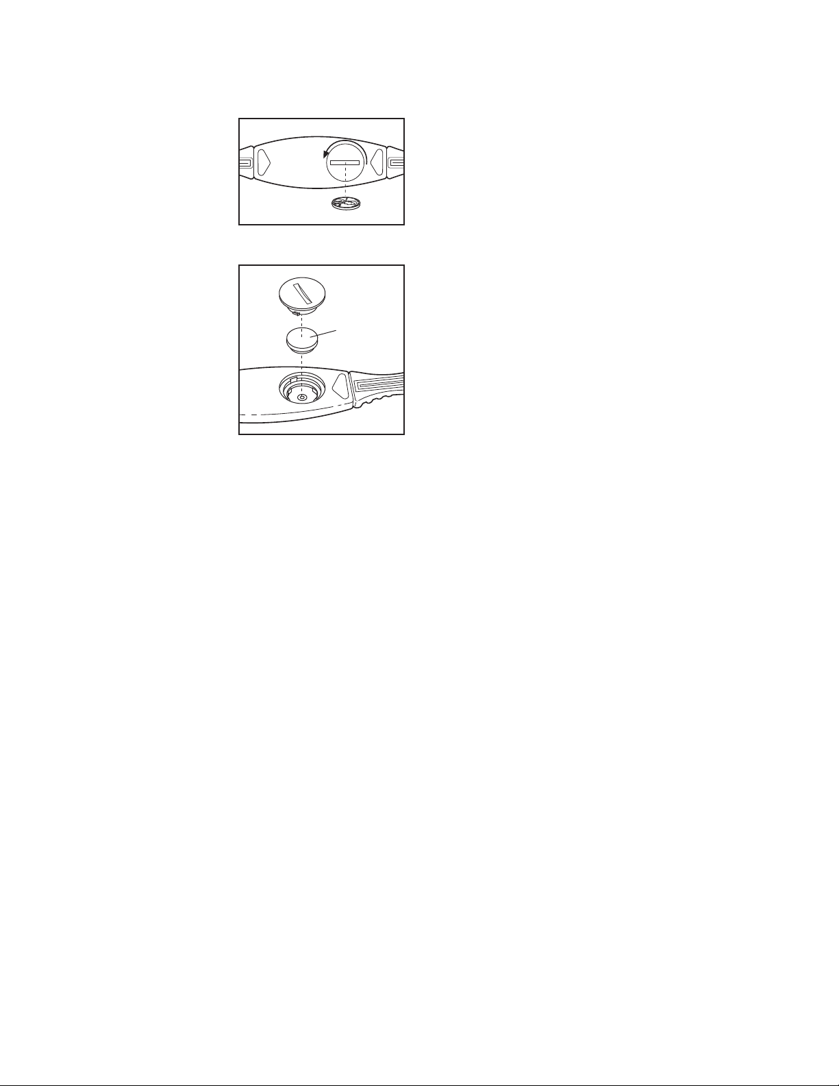
• If the chest pulse sensor does not function properly
after you have followed all of the above instructions,
the battery should be replaced in the following way:
Locate the battery
over on the back of
c
the sensor unit.
Insert a coin into the
slot in the cover,
turn the cover counterclockwise, and
remove the cover.
Remove the old
battery and insert a
new CR 2032 battery. Make sure
that the battery is
turned so the writing is on top.
Replace the battery
cover and turn it
clockwise to close
it.
CR 2032
Battery
CHEST PULSE SENSOR CARE
• Thoroughly dry the chest pulse sensor after each
se. The chest pulse sensor is activated when the
u
electrode areas are wetted and the chest pulse sen-
or is put on; the chest pulse sensor shuts off when
s
it is removed and the electrode areas are dried. If
the chest pulse sensor is not dried after each use, it
may remain activated longer than necessary, draining the battery prematurely.
• Store the chest pulse sensor in a warm, dry place.
Do not store the chest pulse sensor in a plastic bag
or other container that may trap moisture.
• Do not expose the chest pulse sensor to direct
sunlight for extended periods of time. Do not expose
the chest pulse sensor to temperatures above 50° C
(122° F) or below -10° C (14° F).
• Do not excessively bend or stretch the sensor unit
when using or storing the chest pulse sensor.
• Clean the sensor unit using a damp cloth—never
use alcohol, abrasives, or chemicals. The chest
strap may be hand washed and air dried.
9
 Loading...