

Headux TitanMig Pulse 2700, TitanMig Pulse 5000, TitanMig Pulse 3500, TMP3500, TMP5000 Operation Manual
...Page 1
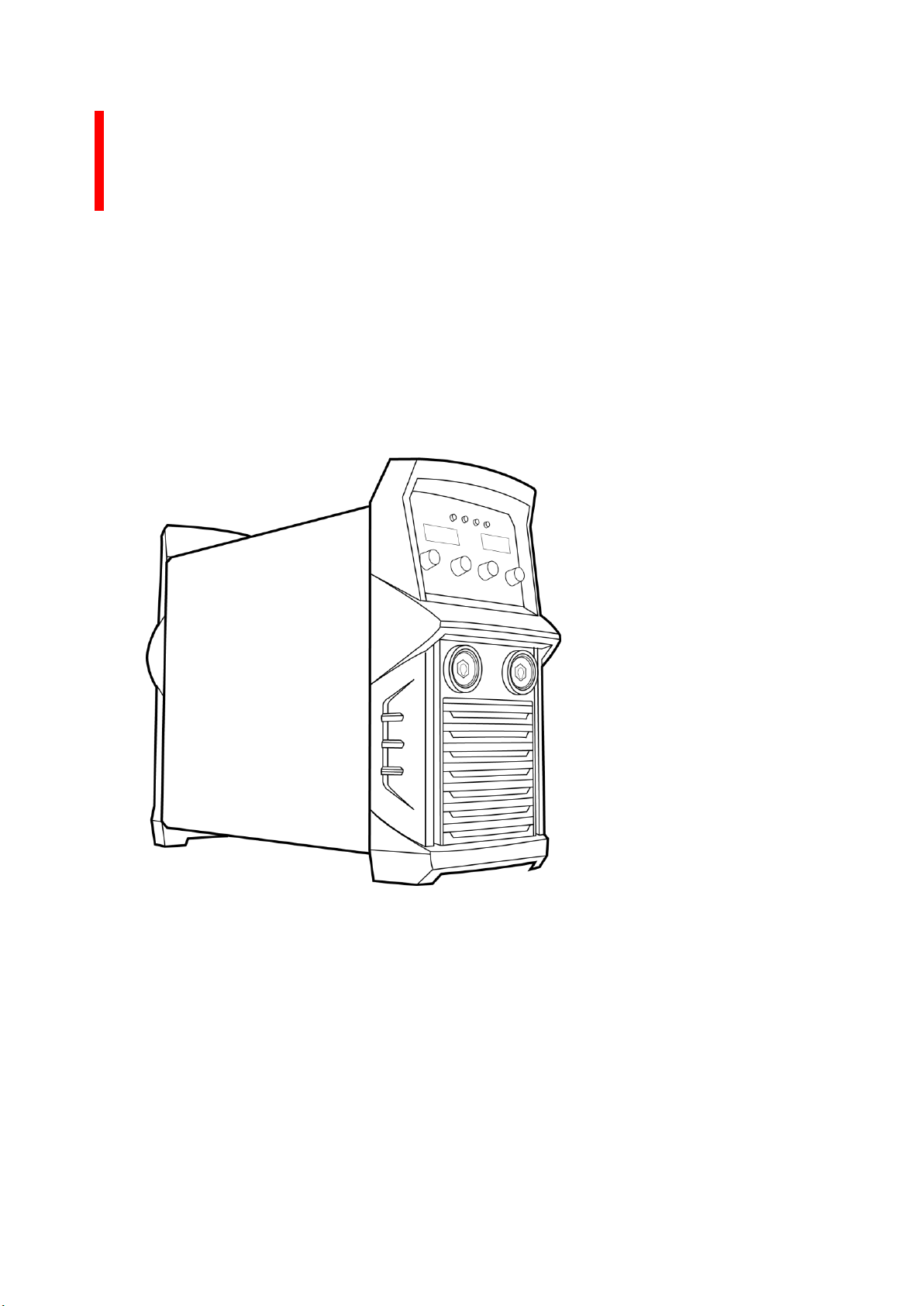
TitanMig Pulse 2700/3500/5000
Operation Manual
Operating manual EN
Brugsanvisning DA
Gebrauchsanweisung DE
Manual de instrucciones ES
Käyttöohje FI
Manuel d’utilisation FR
Manuale d’uso IT
Gebruiksaanwijzing NL
Bruksanvisning NO
Instrukcja obsługi PL
Manual de utilização PT
Инструкции по эксплуатации RU
Bruksanvisning SV
操作手册 CN
TitanMig Pulse 2700/3500/5000 MIG/TIG/Stick Welder
Model No. TMP2700, TMP3500, TMP5000 Issue. A 05/16
Page 2

TitanMig Pulse 2700/3500/5000 Operators Manual
Issue. A 0516
Page 3

Welcome:
Thank you for your purchase of your new Weldtronic product. The Weldtronic product range provides
you with quality and reliability.
This product is supported by our extensive service network. In the unlikely event of a problem occurring
please call your local distributor.
Please record below the details from your product as these will be required for warranty purposes and to
ensure you get the correct information should you require assistance or spare parts.
Date purchased: ________________________________________________________________________
From where: ___________________________________________________________________________
Serial No: ____________________________________________________________________________
(The serial number will be located on the equipment data plate underneath or on the rear panel)
This Operating manual has been designed to instruct you on the correct use and operation of your
Weldtronic product. Information is a guide and we assume no liability for its use.
Please take the time to read the entire manual paying particular attention to the Safety Precautions. They
will help you to avoid potential hazards that may exist when working with this product.
2 Year Warranty Statement.
This product is covered by a 2 Year Warranty Parts & Labour Warranty.
This warranty does not cover freight or goods that have been interfered with.
All goods in question must be repaired by an authorized repair agent as appointed by Weldtronic.
Warranty does not cover abuse, misuse, accident, theft or general wear & tear.
New product will not be supplied unless Weldtronic International P/L has inspected product
returned for warranty and agrees to replace the product.
Product will only be replaced if repair is not possible.
Warranty will be considered void if the 15 Amp primary power Input Plug is modified or replaced
to fit a domestic 10A primary power input Plug.
Warranty will be considered void if the equipment is powered from an unsuitable engine driven
generator.
Warranty will be considered void if no proof of purchase can be provided.
Warranty will be considered void if this product has been altered, tampered or used in any
manner contrary to customary usage or application.
Full warranty details and conditions supplied with this product are shown in the back of this
manual.
TitanMig Pulse 2700/3500/5000 Operators Manual
Issue. A 0516
Page 4

Contents
SAFETY PRECAUTIONS………………….……………………………………………………………..……1
1.0 Preface…………………………………………………………………………………………………11
1.1 General…………………………………………………………………………………………………11
1.2 Introduction………………………………………………………………….………………………12
1.3 Technical Specifications…………………………………………………………..……………13
1.4 Important Notes before use………………………………………………………………...14
1.5 Overview of Power Source……………………………………………………………………15
1.6 Overview of Wire Feeder……………………………………………………………………..16
1.7 Welding Panel , Storage & Recall………………………………………………………….20
1.8 Welding Machine Setup……………………………………………………………………….21
1.9 Welding Machine Status Display…………………………………………………………..22
2.0 Installation……………………………….…………………………………………………………23
3.0 Operation …………………………………………………………………………………………..25
3.1 GMAW (MIG) Welding…………………………………………………………………………26
3.2 MMAW (Stick) Welding……………………………………………………………………….42
3.3 GTAW (TIG) Welding………………………………………………….………………………..44
3.4 Software Updates……………………………………………………………………………….47
3.5 Add Funtions………………………………………………………………………………………54
4.0 Trouble Shooting…………………………………………………………………………………55
4.1 Mig Trouble Shooting………………………………………………………………………….55
4.2 MMAW (Stick) Trouble Shooting…………………………………………………………57
4.3 GTAW (TIG) Trouble Shooting……………………………………………………………..58
4.4 Electrical Trouble Shooting………………………………………………………………...59
5.0 Maintenance…………………………………………………………………………………..….60
6.0 Electrical Diagram……………………………………………………………………………….61
7.0 Warranty Terms & Conditions……………………………………………………………..62
TitanMig Pulse 2700/3500/5000 Operators Manual
Issue. A 0516
Page 5

SAFETY PRECAUTIONS – READ BEFORE USING
These general safety norms cover both arc welding machines and plasma cutting machines unless
otherwise noted.
The equipment must only be used for the purpose it was designed for. Using it in any other way could
result in damage or injury and in breach of the safety rules. Only suitably trained and competent persons
should use the equipment. Operators should respect the safety of other persons.
Prevention against electric shock
The equipment should be installed by a qualified person and in accordance with current standards
in operation. It is the user’s responsibility to ensure that the equipment is connected to a suitable
power supply. Consult with your utility supplier if required.
If earth grounding of the work piece is required, ground it directly with a separate cable.
Do not use the equipment with the covers removed.
Do not touch live electrical parts or parts which are electrically charged.
Turn off all equipment when not in use.
Cables (both primary supply and welding) should be regularly checked for damage and
overheating. Do not use worn, damaged, under sized, or poorly jointed cables.
Ensure that you wear the correct protective clothing, gloves, head and eye protection.
Insulate yourself from work and ground using dry insulating mats or covers big enough to prevent
any physical contact with the work ground.
Never touch the electrode if you are in contact with the work ground, or another electrode from a
different machine.
Do not wrap cables over your body.
Ensure that you take additional safety precautions when you are welding in electrically hazardous
conditions such as damp environments, wearing wet clothing, and metal structures. Try to avoid
welding in cramped or restricted positions.
Ensure that the equipment is well maintained. Repair or replace damaged or defective parts
immediately. Carry out any regular maintenance in accordance with the manufacturer’s
instructions.
Safety against fumes and welding gases
Locate the equipment in a well-ventilated position.
Keep your head out of the fumes. Do not breathe the fumes.
Ensure the welding zone is in a well-ventilated area. If this is not possible provision should be
made for suitable fume extraction.
If ventilation is poor, wear an approved respirator. Read and understand the Material Safety Data
Sheets (MSDS’s) and the manufacturer’s instructions for metals, consumable, coatings, cleaners,
and de-greasers.
Do not weld in locations near any de-greasing, cleaning, or spraying operations. Be aware that
heat and rays of the arc can react with vapours to form highly toxic and irritating gases.
Do not weld on coated metals, unless the coating is removed from the weld area, the area is well
ventilated, and while wearing an air-supplied respirator. The coatings on many metals can give off
toxic fumes if welded.
TitanMig Pulse 2700/3500/5000 Operators Manual
Issue. A 0516 1
Page 6

Prevention against burns and radiation
Arc rays from the welding process produce intense, visible and invisible (ultraviolet and infrared)
rays that can burn eyes and skin.
Wear an approved welding helmet fitted with a proper shade of filter lens to protect your face
and eyes when welding or watching
Wear approved safety glasses with side shields under your helmet.
Never use broken or faulty welding helmets.
Always ensure there are adequate protective screens or barriers to protect others from flash,
glare and sparks from the welding area. Ensure that there are adequate warnings that welding or
cutting is taking place.
Wear suitable protective flame resistant clothing. The sparks and spatter from welding, hot work
pieces, and hot equipment can cause fires and burns
Welding on closed containers, such as tanks, drums, or pipes, can cause them to explode.
Accidental contact of electrode to metal objects can cause arcs, explosion, overheating, or fire.
Check and be sure the area is safe and clear of inflammable material before carrying out any
welding.
Protection against noise
Some welding and cutting operations may produce noise.
Wear safety ear protection to protect your hearing.
Protection from moving parts
When the machine is in operation, keep away from moving parts such as motors and fans. Moving
parts, such as the fan, may cut fingers and hands and snag garments.
Protections and coverings may be removed for maintenance and controls only by qualified
personnel, after first disconnecting the power supply cable.
Replace the coverings and protections and close all doors when the intervention is finished, and
before starting the equipment.
Take care to avoid getting fingers trapped when loading and feeding wire during set up and
operation.
When feeding wire be careful to avoid pointing it at other people or toward your body.
Always ensure machine covers and protective devices are in operation.
Precautions against fire and explosion
Avoid causing fires due to sparks and hot waste or molten metal
Ensure that appropriate fire safety devices are available near the cutting / welding area.
Remove all flammable and combustible materials from the cutting / welding zone and
surrounding areas
Do not cut/weld fuel and lubricant containers, even if empty. These must be carefully cleaned
before they can be cut/welded.
Always allow the cut/welded material to cool before touching it or placing it in contact with
combustible or flammable material.
Do not work in atmospheres with high concentrations of combustible fumes, flammable gases
and dust.
Always check the work area half an hour after cutting to make sure that no fires have begun
TitanMig Pulse 2700/3500/5000 Operators Manual
Issue. A 0516 2
Page 7

Risks due to magnetic fields
The magnetic fields created by high currents may affect the operation of pacemakers or
electronically controlled medical equipment.
Wearers of vital electronic equipment should consult their physician before beginning any arc
welding, cutting, gouging or spot welding operations.
Do not go near welding equipment with any sensitive electronic equipment as the magnetic fields
may cause damage.
RF Declaration
Equipment that complies with directive 2004/108/EC concerning electromagnetic compatibility (EMC) and
the technical requirements of EN60974-10 is designed for use in industrial buildings and not those for
domestic use where electricity is provided via the low voltage public distribution system. Difficulties may
arise in assuring class A electromagnetic compatibility for systems installed in domestic locations due to
conducted and radiated emissions.
In the case of electromagnetic problems, it is the responsibility of the user to resolve the situation. It may
be necessary to shield the equipment and fit suitable filters on the mains supply.
LF Declaration
Consult the data plate on the equipment for the power supply requirements.
Due to the elevated absorbance of the primary current from the power supply network, high power
systems affect the quality of power provided by the network. Consequently, connection restrictions or
maximum impedance requirements permitted by the network at the public network connection point
must be applied to these systems.
In this case the installer or the user is responsible for ensuring the equipment can be connected,
consulting the electricity provider if necessary.
Materials and their disposal
The equipment is manufactured with materials, which do not contain any toxic or poisonous materials
dangerous to the operator.
When the equipment is scrapped, it should be dismantled separating components according to the type of
materials.
Do not dispose of the equipment with normal waste. The European Directive 2002/96/EC on Waste
Electrical and Electronic Equipment states the electrical equipment that has reached its end of life must be
collected separately and returned to an environmentally compatible recycling facility.
Handling of Compressed gas cylinders and regulators
All cylinders and pressure regulators used in welding operations should be handled with care.
Never allow the electrode, electrode holder or any other electrically “hot” parts to touch a cylinder.
Keep your head and face away from the cylinder valve outlet when opening the cylinder valve.
Always secure the cylinder safely.
Never deface or alter any cylinder
TitanMig Pulse 2700/3500/5000 Operators Manual
Issue. A 0516 3
Page 8

EMF Information
Considerations About Welding And The Effects Of Low Frequency Electric And Magnetic Fields Welding
current, as it flows through welding cables, will cause electro-magnetic fields. There has been and still is
some concern about such fields, However, after examining more than 500 studies spanning 17 years of
research, a special blue ribbon committee of the National Research Council concluded that: "The body
of evidence, in the committees judgment, has not demonstrated that exposure to power-frequency
electric and magnetic fields is a human-health hazard." However studies are still going forth and evidence
continues to be examined. Until the final conclusions of the research are reached, you may wish to
minimize your exposure to electromagnetic fields when welding or cutting.
To reduce magnetic fields in the workplace, use the following procedures:
Keep cables close together by twisting or taping them.
Arrange cables to one side and away from the operator.
Do not coil or drape cables around your body.
Keep welding power source and cables as far away from operator as practical.
Connect work clamp to work piece as close to the weld as possible.
Limitations of warranty declaration regarding machine use
▲ The welding machine(s) described in this manual are designed exclusively for electrical arc welding
with shielding gases Argon, CO2 or Ar + CO2 mixture(s) employing MIG or MAG technology. Using
this machine for other purposes is not allowed. Using this machine in opposition with instructions
can put the welder in danger. Damage can occur to the welding machine if not operated according
to this manual. Failures and accidents due to such actions are not covered by warranty, nor can the
producer be held responsible
TitanMig Pulse 2700/3500/5000 Operators Manual
Issue. A 0516 4
Page 9

Symbol usage
This group of symbols means Warning! Watch
Out! Possible ELECTRIC SHOCK, MOVING PARTS,
and HOT PARTS hazards.
Consult symbols and related instructions below for
necessary actions to avoid the hazards.
Means Warning! Watch Out! There are possible hazards with this procedure! The possible
hazards are shown in the adjoining symbols.
▲ Marks a special safety message.
Arc Welding Hazards
▲ The symbols shown below are used throughout this manual to call attention to and identify
possible hazards. When you see the symbol, watch out, and follow the related instructions to avoid
the hazard. The safety information given below is only a summary of the more complete safety
information found in the Safety Standards. Read and follow all Safety Standards.
▲ Only qualified persons should install, operate, maintain, and repair this unit.
▲ During operation, keep everybody, especially children, away.
ELECTRIC SHOCK can kill.
Touching live electrical parts can cause fatal shocks or severe burns. The electrode and
work circuit is electrically live whenever the output is on. The input power circuit and
machine internal circuits are also live when power is on. In semi-automatic or automatic
wire welding, the wire, wire reel, drive roll housing, and all metal parts touching the
welding wire are electrically live. Incorrectly installed or improperly grounded equipment
is a hazard.
Do not touch live electrical parts.
Wear dry, hoIe-free insulating gloves and body protection.
Insulate yourself from work and ground using dry insulating mats or covers big enough to prevent any
physical contact with the work or ground.
Do not use AC output in damp areas, if movement is confined, or if there is a danger of falling.
Use AC output ONLY if required for the welding process.
If AC output is required, use remote output control if present on unit.
Disconnect input power or stop engine before installing or servicing this equipment. Lockout/tagout input
power according to Safety Standards.
Properly install and ground this equipment according to its Owner’s Manual and national, state, and local
codes.
Always verify the supply ground — check and be sure that input power cord ground wire is properly
connected to ground terminal in disconnect box or that cord plug is connected to a properly grounded
receptacle outlet.
TitanMig Pulse 270/3500/5000 Operators Manual
Issue. A 0516 5
Page 10

When making input connections attach proper grounding conductor first - double-check connections.
Frequently inspect input power cord for damage or bare wiring replace cord immediately if damaged —
bare wiring can kill.
Turn off all equipment when not in use.
Do not use worn, damaged, undersized, or poorly spliced cables.
Do not drape cables over your body.
If earth grounding of the work piece is required, ground it directly with a separate cable.
Do not touch electrode if you are in contact with the work, ground, or another electrode from a different
machine.
Use only WeII-maintained equipment. Repair or replace damaged parts at once. Maintain unit according to
manual.
Wear a safety harness if working above floor level.
Keep all panels and covers securely in place.
Clamp work cable with good metal-to-metal contact to work piece or worktable as near the weld as
practical.
Insulate work clamp when not connected to work piece to prevent contact with any metal object.
Do not connect more than one electrode or work cable to any single weld output terminal.
▲ SIGNIFICANT DC VOLTAGE exists after removal of input power on inverters.
Turn off inverter, disconnect input power, and discharge input capacitors according to instructions in
Maintenance Section before touching any parts.
FUMES AND GASES can be hazardous.
Welding produces fumes and gases. Breathing these fumes and gases can be hazardous
to your health.
Keep your head out of the fumes. Do not breathe the fumes.
If inside, ventilate the area and/or use exhaust at the arc to remove welding fumes and gases.
If ventilation is poor use an approved air-supplied respirator.
Read the Material Safety Data Sheets (MSDSs) and the manufacturers’ instructions for metals,
consumables, coatings, cleaners, and degreasers.
Work in a confined space only if it is well ventilated, or while wearing an air-supplied respirator. Always
have a trained watch-person nearby. Welding fumes and gases can displace air and lower the oxygen level
causing injury or death. Be sure the breathing air is safe.
Do not weld in locations near degreasing, cleaning, or spraying operations. The heat and rays of the arc can
react with vapours to form highly toxic and irritating gases.
Do not weld on coated metals, such as galvanized, lead, or cadmium plated steel, unless the coating is
removed from the weld area, the area is well ventilated, and if necessary, while wearing an air-supplied
respirator. The coatings and any metals containing these elements can give off toxic fumes if welded.
TitanMig Pulse 270/3500/5000 Operators Manual
Issue. A 0516 6
Page 11
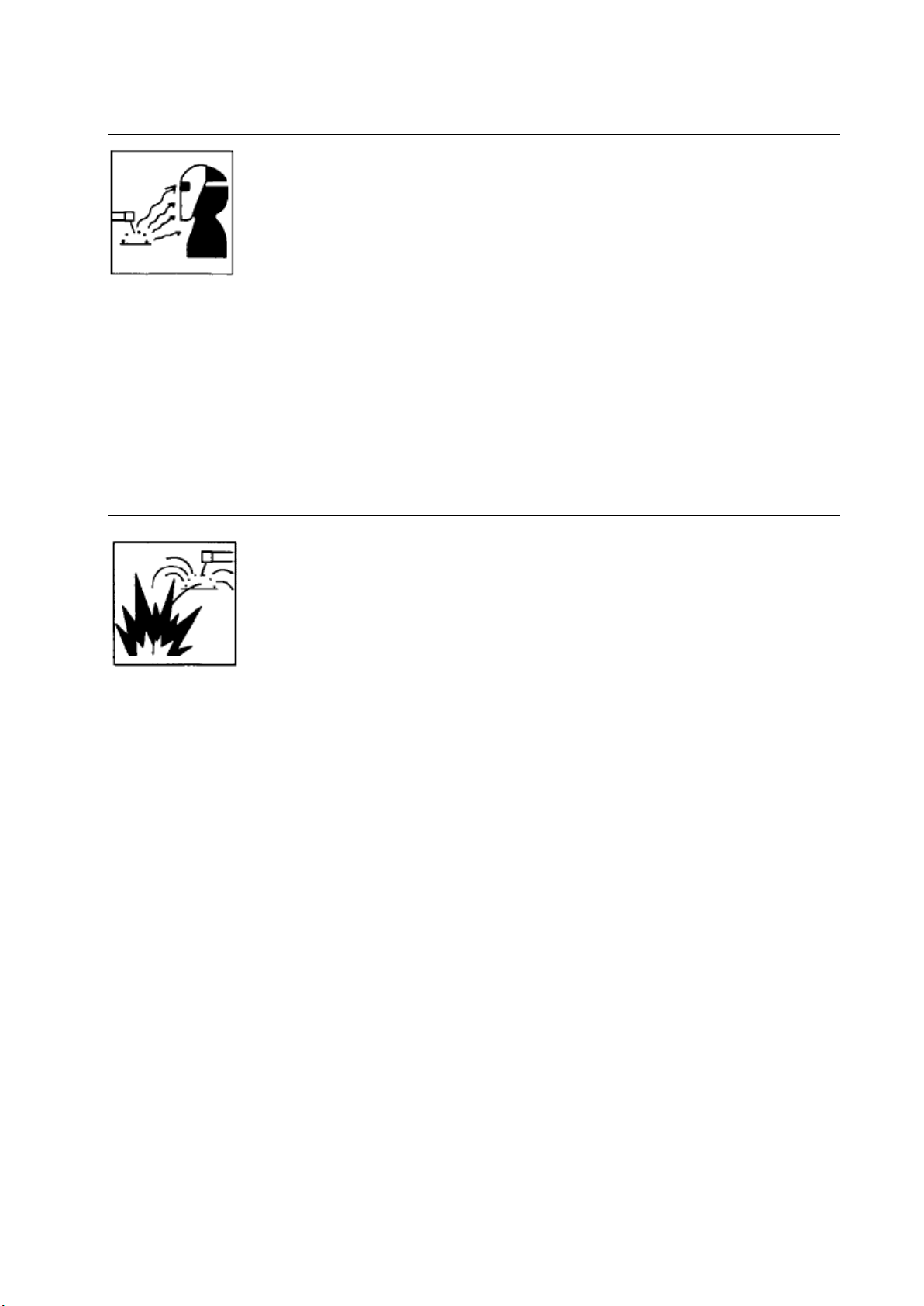
ARC RAYS can burn eyes and skin.
Arc rays from the welding process produce intense visible and invisible (ultraviolet and
infrared) rays that can burn eyes and skin. Sparks fly off from the weld.
Wear a welding helmet fitted with a proper shade of filler to protect your face and eyes when welding or
watching (see Safety Standards).
Wear approved safety glasses with side shields under your helmet.
Use protective screens or barriers to protect others from flash and glare; warn others not to watch the arc.
Wear protective clothing made from durable, flame-resistant material (leather and wool) and foot
protection.
WELDING can cause fire or explosion.
Welding on closed containers, such as tanks, drums, or pipes, can cause them to blow
up. Sparks can fly off from the welding arc. The flying sparks, hot work piece, and hot
equipment can cause fires and burns. Accidental contact of electrode to metal objects
can cause sparks, explosion, overheating, or lure. Check and be sure the area is safe
before doing any welding.
Protect yourself and others from flying sparks and hot metal.
Do not weld where flying sparks can strike flammable material.
Remove all flammables within 35 ft (10.7 m) of the welding arc. If this is not possible, tightly cover them
with approved covers.
Be alert that welding sparks and hot materials from welding can easily go through small cracks and
openings to adjacent areas.
Watch for fire, and keep a fire extinguisher nearby.
Be aware that welding on a ceiling, floor, bulkhead, or partition can cause fire on the hidden side.
Do not weld on closed containers such as tanks, drums, or pipes, unless they are properly prepared
according to Safety Standards.
Connect work cable to the work as close to the welding area as practical to prevent welding current from
travelling long, possibly unknown paths and causing electric shock and fire hazards.
Do not use welder to thaw frozen pipes.
Remove stick electrode from holder or cut off welding wire at contact tip when not in use.
Wear oil-free protective garments such as leather gloves, heavy shirt, cuff less trousers, high shoes, and a
cap.
Remove any combustibles, such as butane lighter or matches, from your person before doing any welding.
TitanMig Pulse 270/3500/5000 Operators Manual
Issue. A 0516 7
Page 12
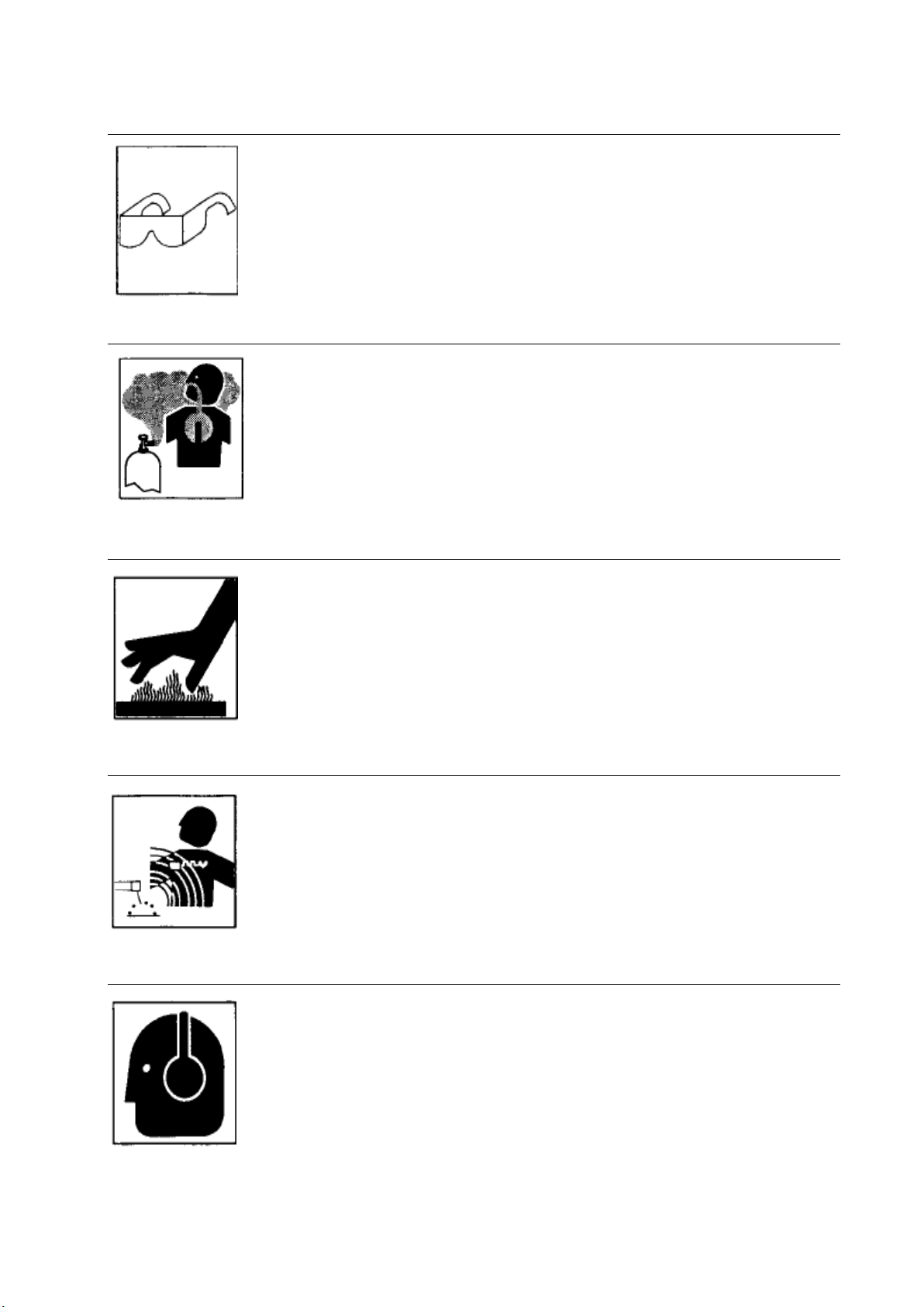
FLYING METAL can injure eyes.
Welding, chipping, wire brushing, and grinding cause sparks and flying metal. As
welds cool, they can throw off slag.
Wear approved safety glasses with side shields even under your welding helmet.
BUILDUP OF GAS can injure or kill.
Shut off shielding gas supply when not in use.
Always ventilate confined spaces or use approved air-supplied respirator.
HOT PARTS can cause severe burns.
Do not touch hot parts bare handed.
Allow cooling period before working on gun or torch.
MAGNETIC FIELDS can affect pacemakers.
Pacemaker wearers keep away.
Wearers should consult their doctor before going near arc welding, gouging, or spot
welding operations.
NOISE can damage hearing.
Noise from some processes or equipment can damage hearing.
Wear approved ear protection if noise level is high.
TitanMig Pulse 270/3500/5000 Operators Manual
Issue. A 0516 8
Page 13
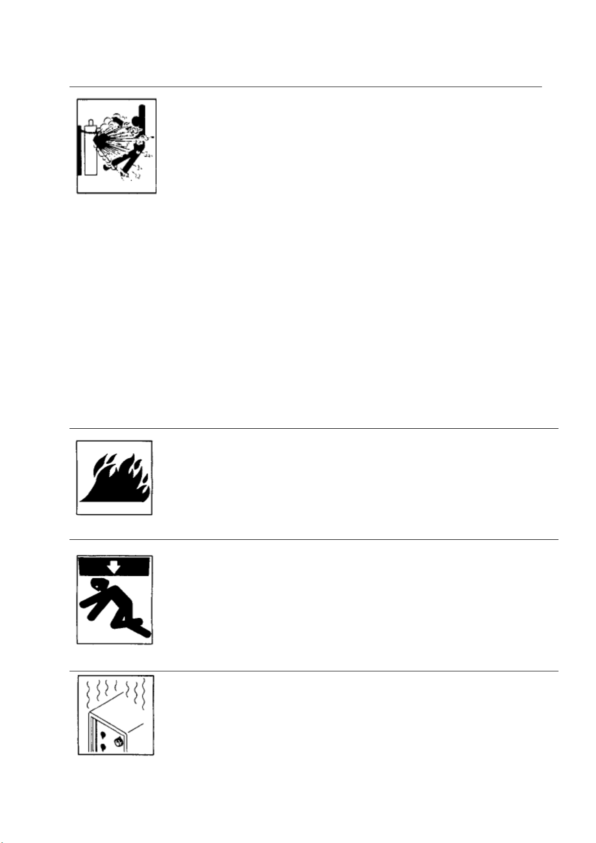
CYLINDERS can explode if damaged.
Shielding gas cylinders contain gas under high pressure. If damaged, a cylinder can
explode. Since gas cylinders are normally part of the welding process, be sure to treat
them carefully.
Protect compressed gas cylinders from excessive heat, mechanical shocks, slag, open flames, sparks, and
arcs.
Install cylinders in an upright position by securing to a stationary support or cylinder rack to prevent falling
or tipping.
Keep cylinders away from any welding or other electrical circuits.
Never drape a welding torch over a gas cylinder.
Never allow a welding electrode to touch any cylinder.
Never weld on a pressurized cylinder - explosion will result.
Use only correct shielding gas cylinders, regulators, hoses, and fittings designed for the specific application:
maintain them and associated parts in good condition.
Turn face away from valve outlet when opening cylinder valve.
Keep protective cap in place over valve except when cylinder is in use or connected for us
FIRE OR EXPLOSION hazard.
Do not install or place unit on, over, or near combustible surfaces.
Do not install unit near flammables.
Do not overload building wiring — be sure power supply system is properly sized, rated,
and protected to handle this unit.
FALLING UNIT can cause injury.
Use lifting eye to lift unit only, NOT running gear, gas cylinders, or any other accessories.
Use equipment of adequate capacity to lift and support unit.
If using lift forks to move unit, be sure forks are long enough to extend beyond opposite
side of unit.
OVERUSE can cause OVERHEATING
Allow cooling period; follow rated duty cycle.
Reduce current or reduce duty cycle before starting to weld again.
Do not block or filter airflow to unit.
TitanMig Pulse 270/3500/5000 Operators Manual
Issue. A 0516 9
Page 14
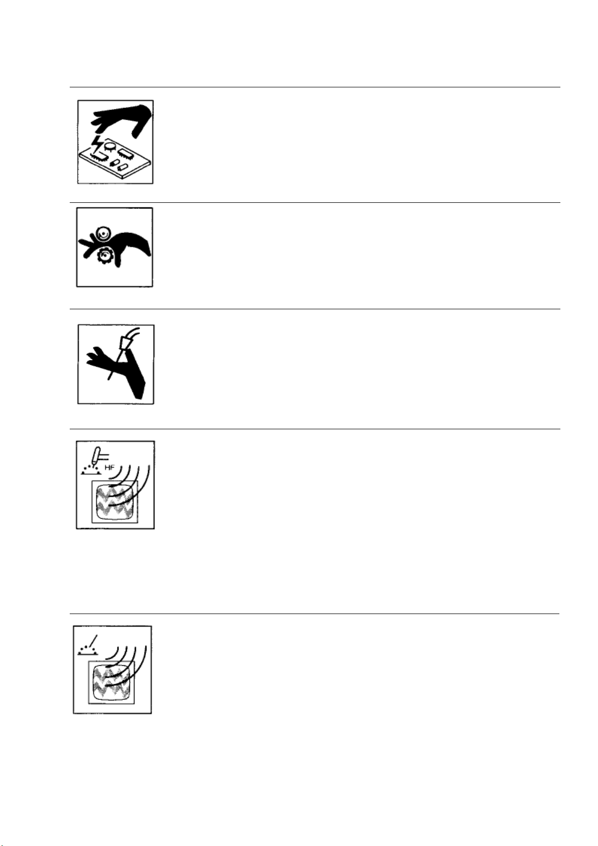
STATIC (ESD) can damage PC boards.
Put on grounded wrist strap BEFORE handling boards or parts.
Use proper static-proof bags and boxes to store, move, or ship PC boards.
MOVING PARTS can cause injury.
Keep away from moving parts.
Keep away from pinch points such as drive rolls.
WELDING WIRE can cause injury.
Do not press gun trigger until instructed to do so.
Do not point gun toward any part or the body, other people, or any metal when
threading welding wire.
H.F. RADIATION can cause interference.
High frequency (HF,) can interfere with radio, navigation, safety services, computers, and
communications equipment.
Have only qualified persons familiar with electronic equipment perform this installation.
The user is responsible for having a qualified electrician promptly correct any
interference problem resulting from the installation.
If notified by the FCC about interference, stop using the equipment at once.
Have the installation regularly checked and maintained.
Keep high-frequency source doors and panels tightly shut. Keep spark gaps at correct setting, and use
grounding and shielding to minimize the possibility of interference.
ARC WELDING can cause interference.
Electromagnetic energy can interfere with sensitive electronic equipment such as
computers and computer-driven equipment such as robots.
Be sure all equipment in the welding area is electromagnetically compatible.
To reduce possible interference, keep weld cables as short as possible, close together,
and down low, such as on the floor.
Locate welding operation 100 meters from any sensitive electronic equipment.
Be sure this welding machine is installed and grounded according to this manual.
If interference still occurs, the user must take extra measures such as moving the welding machine, using
shielded cables, using line filters, or shielding the work area
TitanMig Pulse 270/3500/5000 Operators Manual
Issue. A 0516 10
Page 15

1.0 Preface
1.1 General
Congratulations on choosing TitanMig Pulse welding machine. Used correctly, our products can
significantly increase the productivity of your welding, and provide years of economical service.
This operating manual contains important information on the use, maintenance and safety of our
product. Please read the manual carefully before using the equipment for the first time.
For your own safety and that of your working environment, pay particular attention to the safety
instructions in the manual.
For more information on our products, contact us, consult an authorized dealer, or visit our website.
The specifications presented in this manual are subject to change without prior notice.
Important notes
Items in the manual that require particular attention in order to minimize damage and personal harm
are indicated with the ’NOTE!’ notation. Read these sections carefully and follow their instructions.
Disclaimer
While every effort has been made to ensure that the information contained in this guide is accurate
and complete, no liability can be accepted for any errors or omissions. We reserve the right to change
the specification of the product described at any time without prior notice.
TitanMig Pulse 270/3500/5000 Operators Manual
Issue. A 0516 11
Page 16

1.2 Introduction
TitanMig Pulse 2700/3500 and 5000 are CC/CV welding power sources designed for demanding
professional use. They are suitable for synergic Pulsed MIG/MAG, Synergic 1-MIG/MAG,Lift-Tig and MMA
welding in DC current.
TitanMig Pulse 2700/3500/5000 product range offers both technical and commercial welding solutions
matching a wide range of applications from sheet metal fabrication to heavy industry segments.
The TitanMig Pulse 2700/3500/5000 power sources are digitised microprocessor-controlled inverter
power sources.
The TMP-series power sources 2700/3500/5000 are used in workshops and industry for manual and
automated applications with classical steel, galvanised sheets, chrome/nickel and aluminium.
The TitanMig Pulse 2700 features an integral 4-roller drive. There is no longer an interconnecting hose
pack between the power source and wire-feed unit. Its compact design makes the TMP 2700 particularly
suitable for mobile applications on building sites or in repair workshops..
The TMP 4000/5000 power sources are designed for: -- Mechanical engineering - Steel engineering - Crane
construction - Shipbuilding - Boiler manufacture- Automobile and component supply industry - Machinery
and rail vehicle construction - Chemical plant construction - Equipment construction etc.
All models are multiprocess devices: - MIG/MAG welding - TIG welding with touchdown ignition- Manual
metal arc welding
TitanMig Pulse 270/3500/5000 Operators Manual
Issue. A 0516 12
Page 17

TMP 5000
TMP 3500
TMP 2700
Power Supply / Phases (V-Ph)
AC380V±15%~50/60Hz
240 V 1 Phase
Duty Cycle@40°c to AS/NZ60974
60% @ 500 Amps MIG
60% @ 350 Amps MIG
35% @ 275Amps MIG
60% @ 500 Amps MMA
60% @ 350 Amps MMA
60% @ 194Amps MMA
Rated Output Power Rate
500A/40V
350A/34V
250/26.5V
Rated Input Current
36A
21A
50 A
Power Factor
≥0.85
0.75
Efficiency
90%
90%
Gas pre-flow time (Preg)
0~15.0s
Post-flow time(Posg)
0~15.0s
Soft start speed (Stfd)
Auto,0.5~22m/min
Wire Feeder Type
Gear Driven 4 Roll
Gear Driven 4 Roll
Gear Driven 4 Roll
Protection Class
IP 21S
IP 21S
IP 21S
Insulation Class
H H H
Dimensions Power Source (LxWxH)
685x295x560mm
685x295x560mm
685x295x560mm
Weight Power Source
53 Kg
52Kg
38 Kg
Dimensions Wire Feeder (LxWxH)
630x235x420mm
630x235x420mm
685x295x560mm
Weight Wire Feeder
16 Kg
16 Kg
Length of Interconnecting Cable
5m/10 m/15m
5m/10 m/15m
1.3 Technical Specifications
TitanMig Pulse 270/3500/5000 Operators Manual
Issue. A 0516 13
Page 18
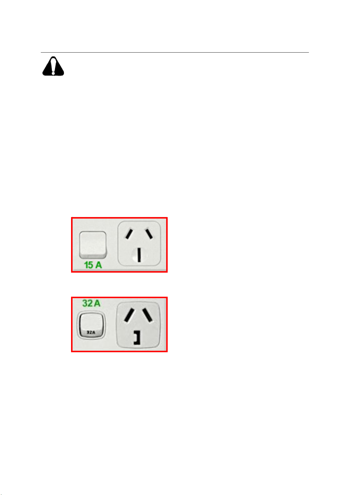
1.4 Important notes before use
▲ Fitted for commissioning
▲ Recommended outlet
▲ Important Note on TitanMig
Pulse 2700 Input Power Supply
This unit has been supplied with
a downgraded 15 Amp primary
supply plug for commissioning
purposes only. You are advised to
upgrade the input power plug
and lead to a minimum of 32A if
sustained usage at maximum
amperage is desired.
▲ WARNING
With the 15A plug supplied it is
recommended that the operator
does not exceed more than
180Amps, as use of higher
amperages over this amount may
lead to failure and overheating of
the 15A plug and circuit, which
may result in electrical supply
component damage and
ultimately electrical fires.
▲ Do not operate or install this equipment without thoroughly reading this manual and the safety
precautions contained throughout.
Save this manual and keep it handy for reference.
Disconnect mains of the semi-automatic welding machine after finishing work or before a long break.
▲ DO NOT make any modifications to the machine. It may cause changes in the features and
deterioration of technical data.
▲ Any adaptations to this machine are prohibited and may void the warranty.
▲ Warranty is void if any damage to the machine is caused by misuse.
Acceptable range of ambient temperature is from 10—40°C.
Acceptable range of humidity is 20°C at 95% humidity.
Specifications may change without previous notice.
TitanMig Pulse 270/3500/5000 Operators Manual
Issue. A 0516 14
Page 19
1
2
3
4
5
6
7
8
9
10
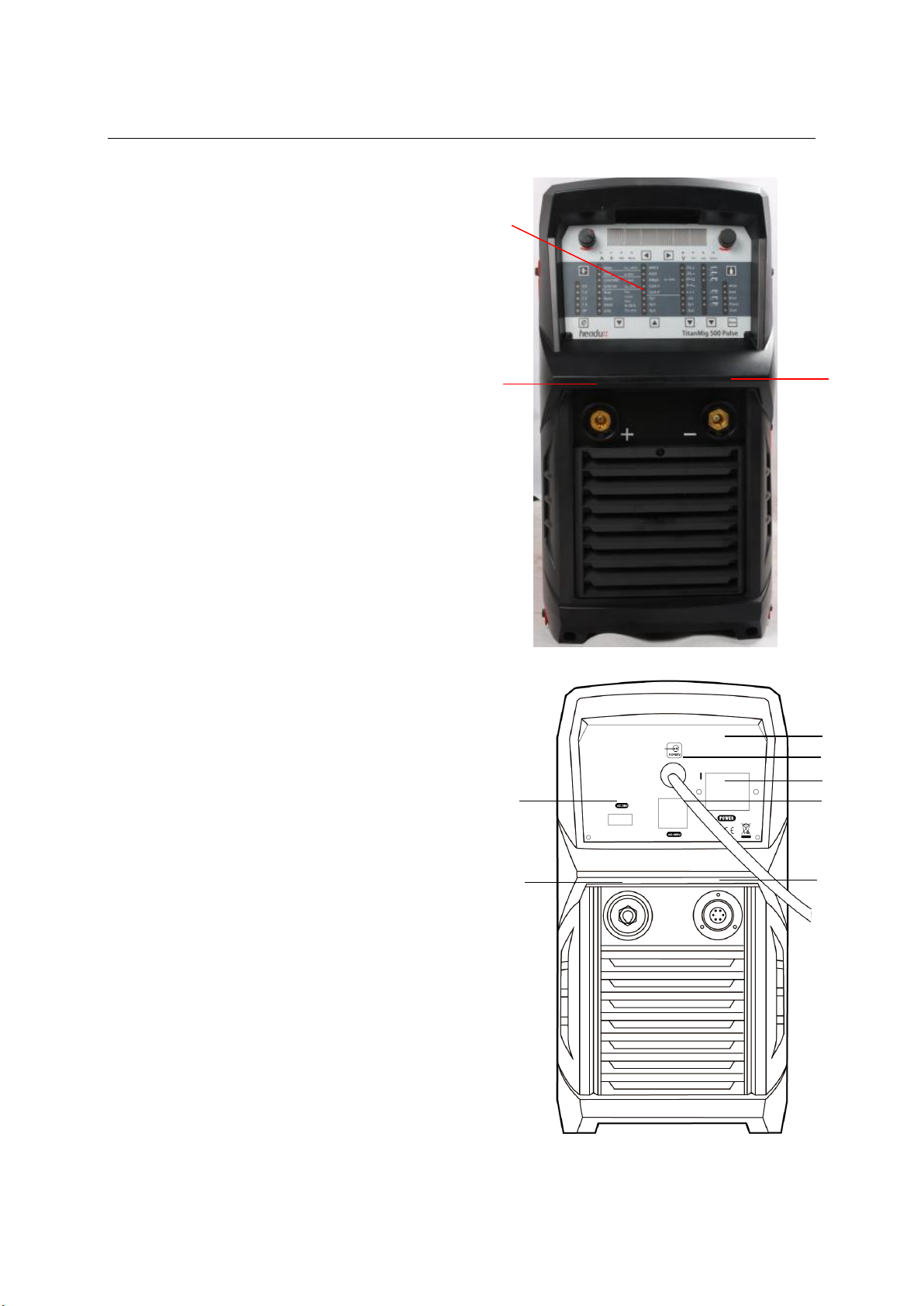
1.5 Overview of Power Source
TitanMig 500 Shown (details will vary from model)
Front View
Power Source Front Panel Layout
1. Control panel
2. Welding Cable Connection
3. Earth Cable Connection
Rear View
4. CO2 Heating Socket
5. Welding Cable Connection
6.Data Plate
7. Primary Input Cable
8. Primary Power Switch
9. Water Cooler Power Socket
10. Control Cable Connection
TitanMig Pulse 270/3500/5000 Operators Manual
Issue. A 0516 15
Page 20
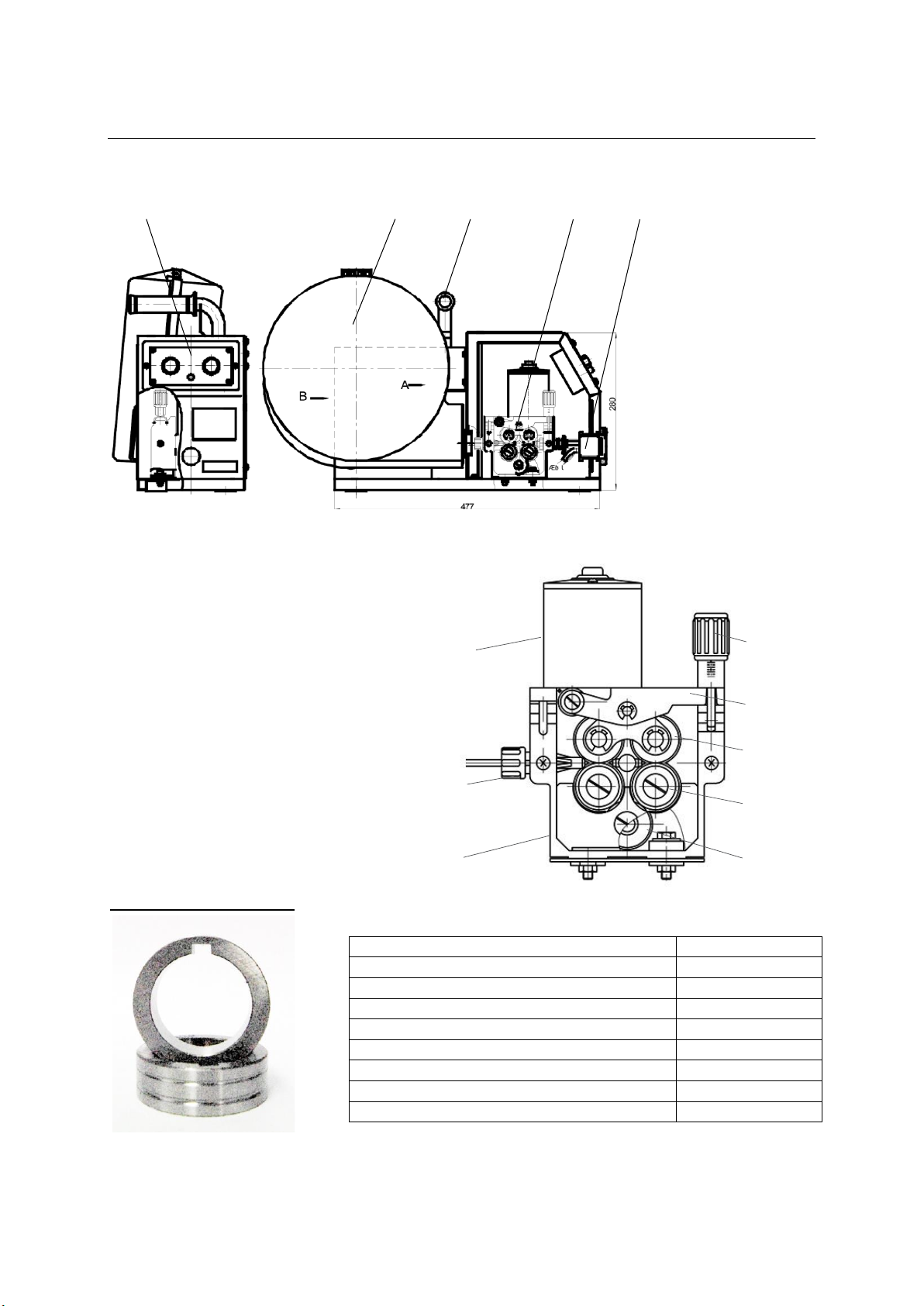
1.5 Overview of Wire Feeder (TMP3500/5000 Only)
1 2
3
4 5
Feed Roll Size & Type
Part Number
Feed Roll 30/10/22 – 0.6/0.8mm Steel
FR3022V0608
Feed Roll 30/10/22 – 0.8/1.0mm Steel
FR3022V0810
Feed Roll 30/10/22 – 0.9/1.2mm Steel
FR3022V0912
Feed Roll 30/10/22 – 1.0/1.2mm Steel
FR3022V1012
Feed Roll 30/10/22 – 1.0/1.2mm Aluminum
FR3022U1012
Feed Roll 30/10/22 – 0.9/1.2mm Aluminum
FR3022U0912
Feed Roll 30/10/22 – 0.9/1.2mm Flux Cored
FR3022K0912
Feed Roll 30/10/22 – 1.2/1.6mm Flux Cored
FR3022K1216
2
3
4
1
5
6
7
8
HF10 Structure
1. Control Box
2. Spool Cover
3. Handle
4. Drive System
5. Gun Connector
HF10 Drive System
1. Drive Gear
2. Wire Feed Rollers
3. Pressure Rollers
4. Pressure Rocker Arm
5. Pressure Adjustment Screw
6. Feed Housing
7. Inlet Guide
8. Drive Motor
HF10 Spare Feed Rollers
TitanMig Pulse 270/3500/5000 Operators Manual
Issue. A 0516 16
Page 21
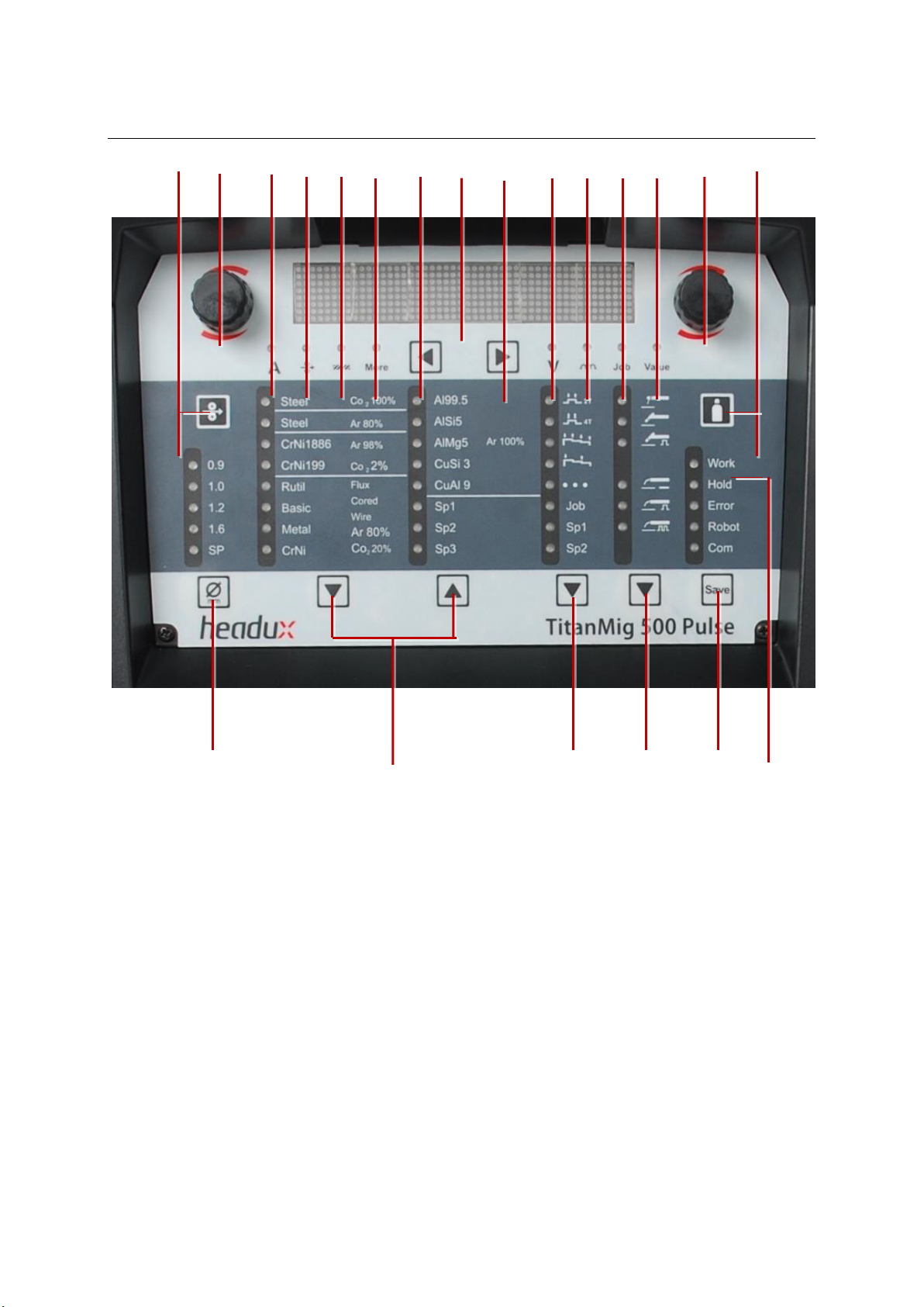
1.6 Description of the control panels
1 2 3 4 5 6 7 8 9 10 11 12 13 14 15
16 17 18 19 20 21
Control Panel
1. Feeder inching button
for feeding the wire electrode into the torch-hosepack without any flow of gas or curren
2. Adjusting dial for altering welding parameters.
If the indicator on the adjusting dial is lit up, then the selected parameter is one that can be altered.
3. Welding current LED
lights up when the welding current parameter is selected
4. Wire feed speed LED
lights up when the wire feed speed parameter is selected
5. Sheet thickness LED
lights up when the sheet thickness parameter is selected
6. More indicator LED
lights up when the other indicator parameter is selected
7. Left parameter selection button
8. Digital display
9. Right parameter selection button
10. Welding voltage LED
lights up when the welding voltage parameter is selected.
11. Droplet detachment correction/arc force dynamic correction/arc force dynamic LED
lights up when the Droplet detachment correction/arc force dynamic correction/ arc force dynamic
TitanMig Pulse 270/3500/5000 Operators Manual
Issue. A 0516 17
Page 22

parameter is selected
1) For MIG welding process: the inductance value 0 is recommended reference range. Value less than
0 give a rougher arc and increased stability. Value greater than 0 give a smoother arc and less spatter.
2) For pulse MIG welding process: The droplet transfer force will be increased according the
inductance value changed from less than 0 to greater than 0.
3) For MMA welding process: the arc force value 0 means soft and spatter small arc, value 100 means
hard and stable arc. When the display value is Job, the welding parameter can be stored and
recalled. Please refer to the details on section 3.2
12. Job no. LED
lights up when the job number parameter is selected
13. Value indicator LED
lights up when the other indicator parameter is selected
14. Adjusting dial for altering welding parameters.
If the indicator on the adjusting dial is lit up, then the selected parameter is one that can be altered
15. Gas test button
for setting the required gas flow rate on the pressure regulator. Gas will flow out for 30 s after
pressing the gas test button. Press the button again to stop the gas test flow before the end of this
period.
16. Wire diameter button
for selecting the diameter of the wire to be used. Parameter SP is reserved for additional wire
diameters. When a wire diameter is selected, the LED behind the relevant wire diameter lights up.
TitanMig Pulse 270/3500/5000 Operators Manual
Issue. A 0516 18
Page 23
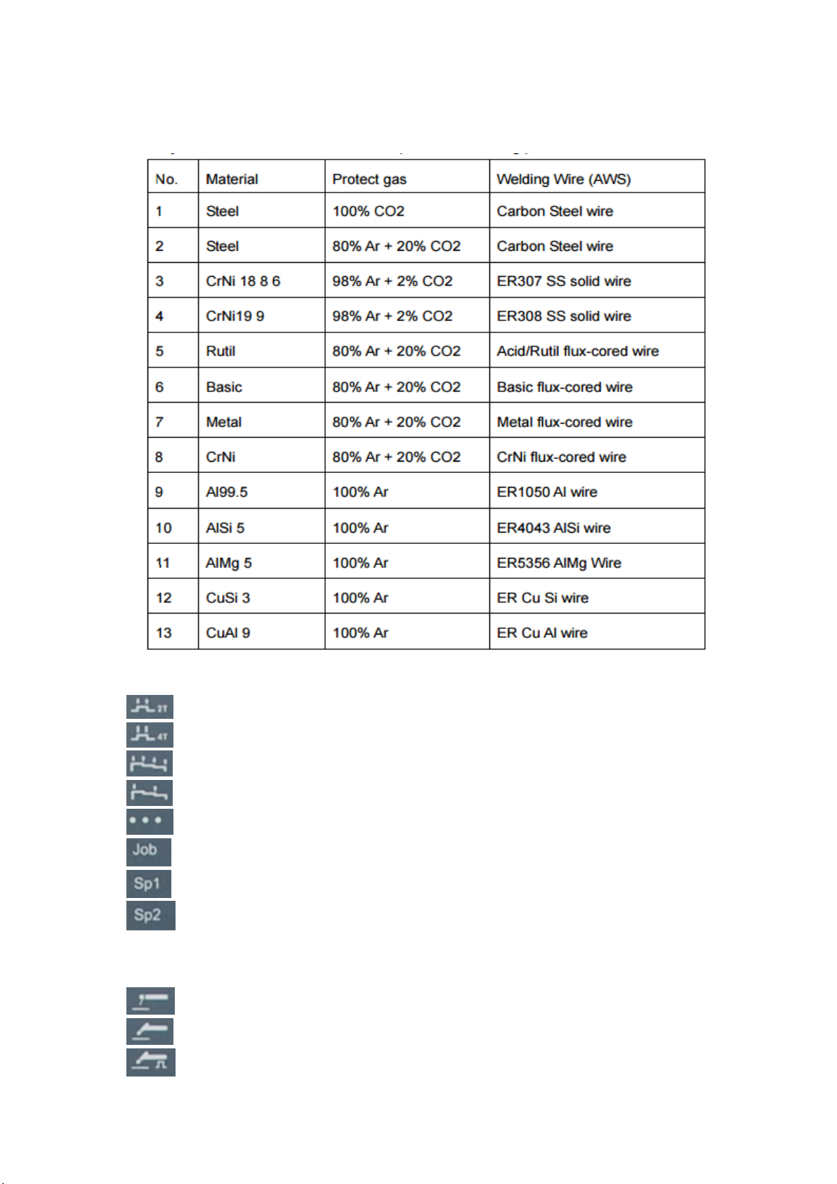
17. Material button
for selecting the filler metal and shielding gas to be used. Parameters SP1 and SP2 are reserved for
additional materials. When a material is selected, the LED behind the relevant filler metal lights up.
18. Mode button
for selecting the mode
2-step mode
4-step mode
Special 4-Step Mode
Special 4-Step Mode
Spot welding mode
For storing the welding parameters
Special Mode 1
Special Mode 2
19. Process button(s)
for selecting the welding process
Manual metal arc welding
Lift-TIG welding
Pulse Lift-TIG welding
TitanMig Pulse 270/3500/5000 Operators Manual
Issue. A 0516 19
Page 24
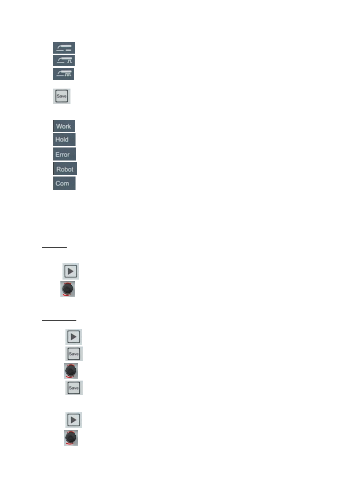
MIG/MAG standard synergic welding
MIG/MAG single pulse synergic welding
MIG/MAG double pulse synergic welding
When a process is selected, the LED on the relevant symbol lights up.
20. Save Button:
For two purposes: store the welding parameters and startup Settings menu
21. Function
Lights up when under welding process.
lights up when under no-load working
lights up if an error has occurred
Lights up when connecting Robot
Lights up when connecting other equipments
1.7 Welding parameters storage and recall
TMP series can store 100 sets of welding parameters (Job0—Job99). The suitable welding parameters
value for different welding application can be stored at any time. Its very convenience to recall the stored
welding parameter when use it next time. No need to preset and adjust the welding parameter value each
time before welding.
For Job 0, it’s specially used for automatically memory storage, which can store the last welding parameter
automatically. The last welding parameter can be recalled from Job 0 when restart the welding machine.
Operation process of recall as follow:
1) Press to choose the display value as job. 23
2) Turn to alter the Job number as 0.
3) The LED will be display the welding parameter which has been used last time.
For Job 1-99, it’s used for manual storage, Operation process as follow:
1) LED displays the welding parameters which will be stored.
2) Press to choose the display value as job.
3) Press , the front of the Job number will display "-"
4) Turn to choose the Job number as “XX”.
5) Press , the LED will display "Finished", means the parameter has been stored to the Job number
“XX”.
Operation process of recall as follow:
1) Press to choose the display value as job.
2) Turn to choose the Job number as “XX”.
3) The LED will be displayed the welding parameters which has been stored in Job “XX”.
TitanMig Pulse 270/3500/5000 Operators Manual
Issue. A 0516 20
Page 25
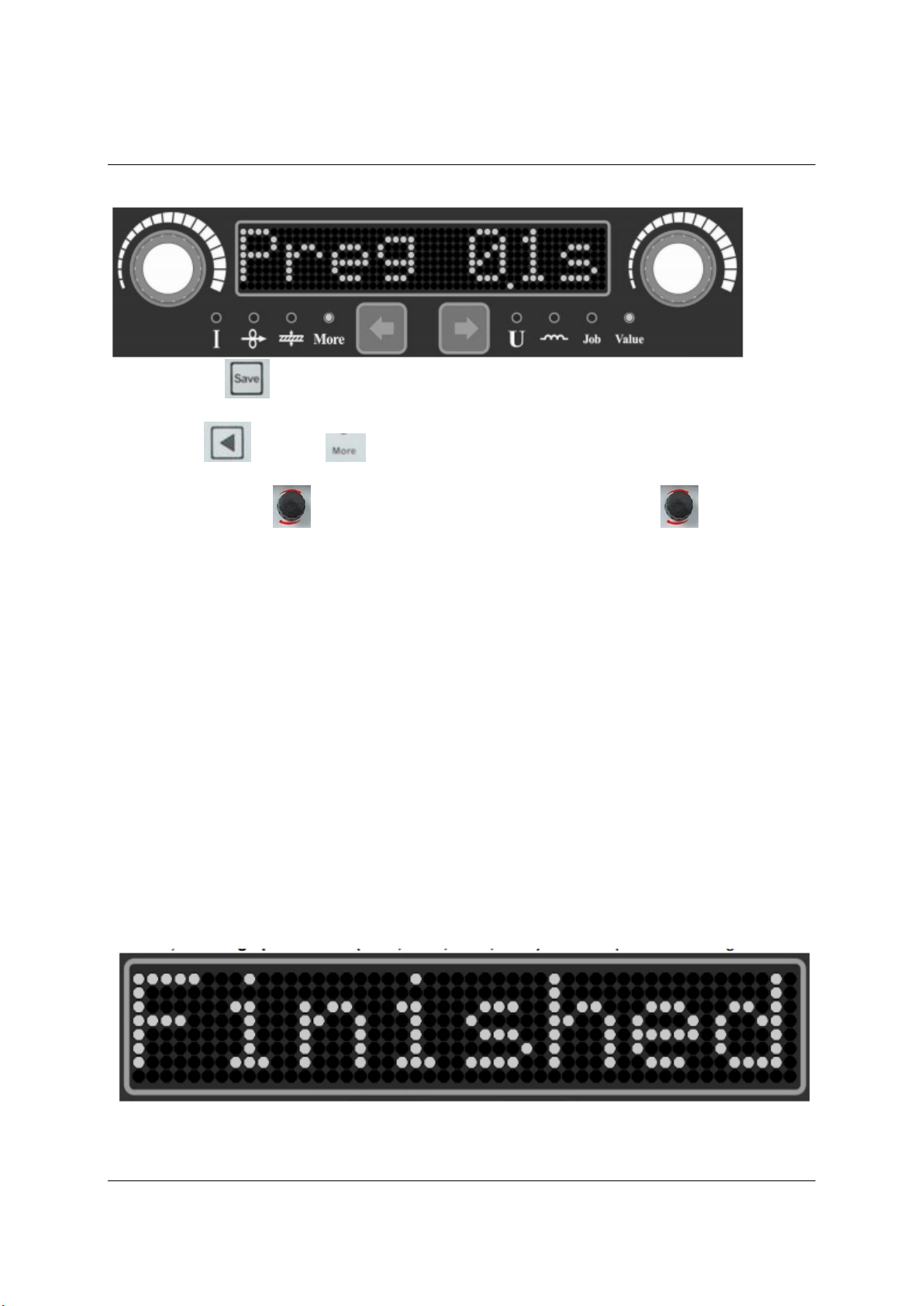
1.8 TMP welding machine startup Settings.
Some welding parameters of TMP series welding machine could be adjusted through the startup Settings
menu, and the operation process as following:
1) Press on key, and turn on the power switch of the machine at the same time.
2) After few seconds, it enters the Startup Settings Menu, and LED display "Preg" as Figure 3.3.1.
3) Press to choose , then the left part of the LED display the parameter name, and
right part of the LED display the parameter value.
4) Turn the left side to choose the parameter name, turn the right side to adjust the
parameter value.
5) Press , the LED will display "Finished", means the parameter has been reset and stored. Then
restart the machine and weld.
Adjustable parameters name of startup Settings as following:
1) Pre-gas flow time (PreG): Adjustable from 0-15s, the default value is 0.1s. It works for MIG, Pulse
MIG, Double Pulse MIG, TIG, Pulse TIG and Spot TIG.
2) Post-gas folw time (PosG) : Adjustable from 0-15s, the default value is 0.1s. It works for MIG, Pulse
MIG, Double Pulse MIG, TIG, Pulse TIG and Spot TIG welding processes.
3) Soft start wire feed speed (Stfd) : Adjustable from 1-22 m/min, and also can be set at automatic. It
works for MIG, Pulse MIG and Double Pulse MIG welding process.
4) Inch wire feed speed (Infd) : Adjustable from 1-22 m/min.
5) Master station MACID (NetP) : Master station MACID of Devicenet: 0-63.
6) Slave station MACID (NetS) : Slave station MACID of Devicenet: 0-63.
7) Device net baud rate (Netb) : 0-125 k, 1-250 k, 2-500 k
8) System Set 1 (Set1) : Bit0 = 1 means allow the simulation remote control, 0 means banned.
9) System Set 2 (Set2) : temporary undefined.
10) Wire feed machine coefficient (Fdp), wire feed machine constant (Fdc) : according the different
wire feed motor, setting up different coefficient. First Type, 24V, 22M/Min, 5A motor: Fdp = 400; Fdc =
426; Second Type, 24 v, 22 m, 3.5 A motor: Fdp = 371; Fdc = 400;
11) Setting up Password (Pas1, Pas2, Pas3, Pas4) : function password settings.
TitanMig Pulse 270/3500/5000 Operators Manual
Issue. A 0516 21
Page 26
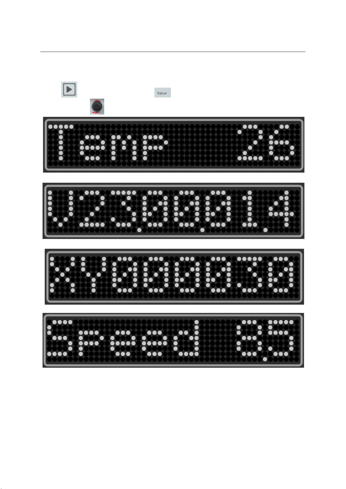
1.9 TMP series welding machine status display
TMP series welding machine can display some information and status of the welder. After startup welding,
the LED will display the company LOGO, hardware, software version, 25 welding process, expert database
material type and whether support DEVICENET and WIFI one by one.
Operation process of the welding machine status display
1) Press to choose the display value as .
2) Turn the left side to show different status of the welding machine as following:
Machine internal temperature is 26℃
Hardware version for V23, software version for V1.4
Machine serial number as XY000030
Actual wire feed speed in 8.5 m/min
TitanMig Pulse 270/3500/5000 Operators Manual
Issue. A 0516 22
Page 27
2.0 Installation
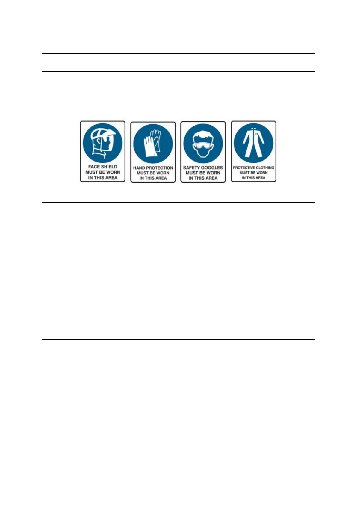
Worker and working area protection
Fumes and gases produced by welding are dangerous for your health. Ventilation in workplace must be
adequate to remove all harmful fumes and gases but not too strong since it could remove the shielding
gas flowing over work piece. Arc welding rays are dangerous for your eyes. The welder must always use a
welding helmet with a minimum protective shade glass No. 10 for MIG Welding. All personal protective
including working clothes, leather apron, gloves, etc. must always be worn when welding or handling the
work piece.
Unpacking
Check the packaging for any signs of damage. Carefully remove the machine and retain the packaging until
the installation is complete.
Positioning of the machine
Place the machine on a firm, dry and level surface. Where possible, do not allow dust or other impurities
to enter the machines cooling air flow. Preferably site the machine above floor level; for example on a
suitable carriage unit.
Notes for positioning the machine
• The surface inclination should not exceed 15 degrees.
• Ensure the free circulation of the cooling air. There must be at least 20 cm of free space in front of
and behind the machine for cooling air to circulate.
• Protect the machine against heavy rain and direct sunshine.
NOTE! The machine should not be operated in the rain as the protection class of the machine, IP21S,
allows for outside preserving and storage only.
NOTE! Never aim metallic grinding spray/sparks towards the equipment.
Input connection
Before connecting the machine you should ensure that the correct supply is available. Details of the
machine requirements can be found on the data plate of the machine or in the technical parameters
shown in the manual.
The equipment should be connected by a suitably qualified competent person. Always ensure the
equipment has a proper grounding.
Never connect the machine to the mains supply with the panels removed.
TitanMig Pulse 270/3500/5000 Operators Manual
Issue. A 0516 23
Page 28
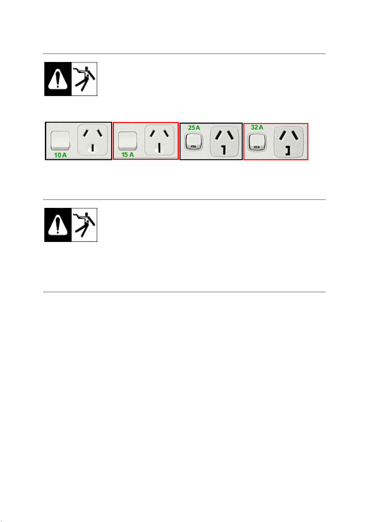
Mains supply – TMP 2700 Only
DO NOT USE FITTED FOR COMMISSION RECOMMEDED TYPE
The INPUT primary cable is supplied with machine. Connect the machine to mains
according to your state legislation of where machine is being used. Connection can
be effected through plug or direct wiring. Supply system should be protected at all
times by the fuse stated in technical data section. Direct connection to mains can
be done by qualified electrical technician only.
Australian 240V Single Phase Plug variants – AS/NZS 3122
Mains supply – TMP 3500 / 5000 MTS Only
The INPUT primary cable is supplied with machine. Connect the machine to mains
according to your state legislation of where machine is being used. Connection can
be effected through plug or direct wiring. Supply system should be protected at all
times by the fuse stated in technical data section. Direct connection to mains can
be done by qualified electrical technician only.
Three phase Plug is not included.
For 350MTS min 20amp 3 phase plug recommended.
For 500MTS min 32 amp 3 phase plug recommended
Output connections
Electrode polarity
In general when using the machine for MMAW (Stick) the electrode holder is connected to the
positive (+) terminal and the work return to the negative (-) terminal.
In general when using the machine for GMAW (Mig) the MIG Torch should be connected to the
positive (+) terminal (Euro Connector) and the work return to the negative (-) terminal.
In general when using the machine Gasless Mig the Mig Torch should be connected to the
negative (-) terminal (Euro Connector) and the work return to the positive (+) terminal.
When using the machine for GTAW (TIG) welding the TIG torch should be connected to the
negative terminal (-) and the work return to the positive (+) terminal
Always consult the electrode manufacturer’s data sheet if you have any doubts.
TitanMig Pulse 270/3500/5000 Operators Manual
Issue. A 0516 24
Page 29
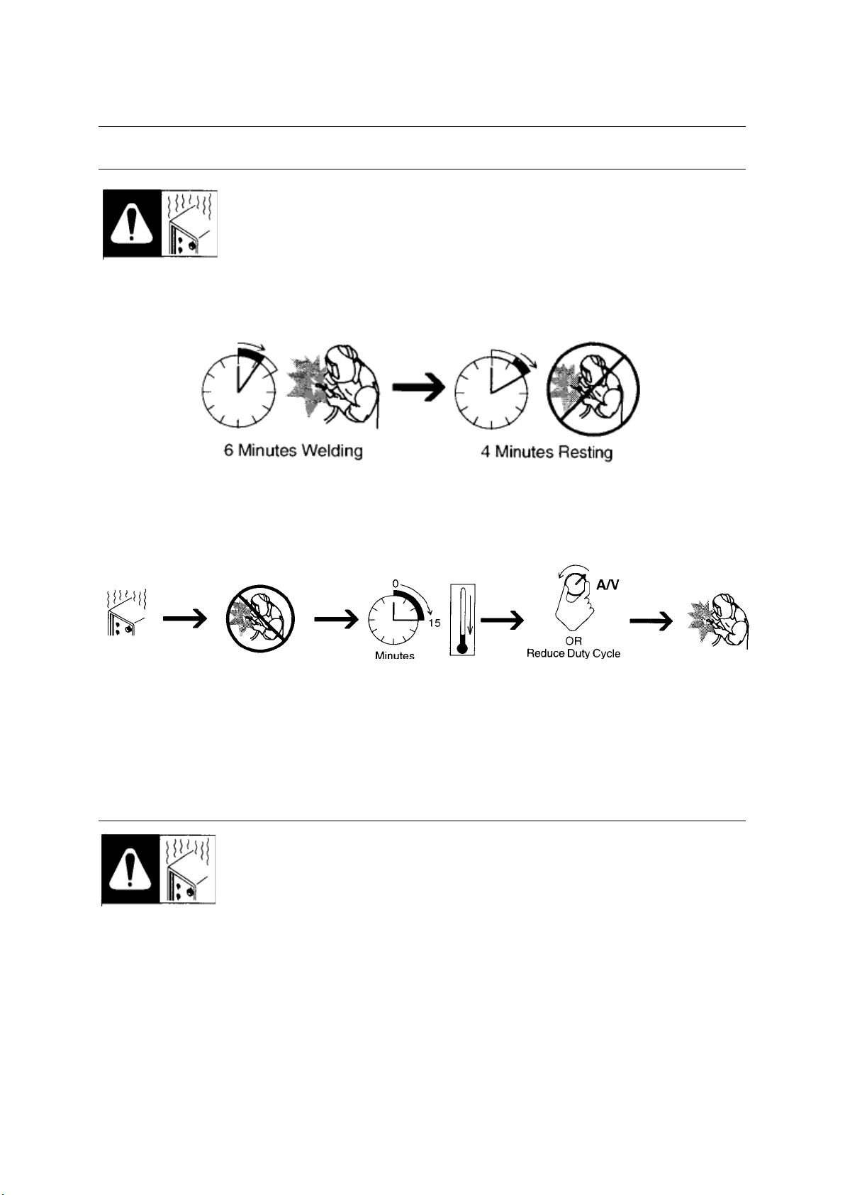
3.0 Operation
Duty cycle and overheating
Duty Cycle is percentage of 10 minutes that unit can weld at rated load without
overheating. If unit overheats, thermostat(s) opens, output stops, and cooling fan
runs. Wait fifteen minutes for unit to cool. Reduce amperage or duty cycle before
welding.
60% Duty Cycle at 180A.
Overheating
▲ Welding machine must be used according to technical data from this manual. If the
machine is overloaded, failures may occur that are not be covered by warranty.
Overload control
Thermal protection is built in the machine's main transformer and Inverter Bridge. If
the machine overheats, thermal fuse will prevent further use and control lamp on
the front panel will light up. In this case the welder must wait until the machine's
temperature drops to normal. Note the machine must be left switched on for the fan
to keep running.
TitanMig Pulse 270/3500/5000 Operators Manual
Issue. A 0516 25
Page 30
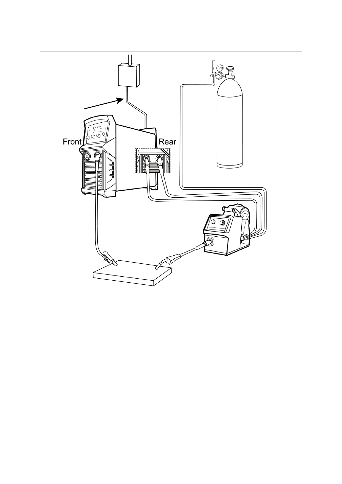
3.1 GMAW (MIG) Welding
Insert the welding torch into the “Euro connector for torch in MIG” output socket on the front
panel of the wire feed unit, and tighten it.
Install the wire spool on the spindle adapter of the wire feed unit.
Connect the cylinder equipped with the gas regulator to the gas inlet of the interconnection cable
set.
Insert the cable plug with work clamp into the “-” output terminal on the front panel of the
welding machine, and tighten it clockwise.
Insert the quick plug of the interconnection cable set into the “+” output terminal of the welding
machine, and tighten it clockwise. Connect the other end connection on the rear of the wire feed
unit
Insert the multi pin plug of the interconnection cable set into the control cable socket of the
welding machine and connect the other connection into the rear of the wire feed unit.
Ensuring that the groove size in the feeding position on the drive roll matches the contact tip size
of the welding torch and the wire size being used. Release the pressure arm of the wire feeder to
thread the wire through the guide tube, and into the drive roll groove. Adjust the pressure arm,
ensuring no sliding of the wire. Too high pressure will lead to wire distortion, which will affect
wire feeding. Press the wire inch button to thread the wire out of the torch contact tip.
TitanMig Pulse 270/3500/5000 Operators Manual
Issue. A 0516 26
Page 31

After being installed according as above, and the power switch on the back panel being switched
on, the machine is started. At this time, the ammeter displays the preset wire feed speed value,
and the voltmeter displays the preset voltage value. Open the cylinder valve, and switch the gas
check switch to the “GAS CHECK” position. Adjust the gas regulator to get the correct gas flow.
After setting, switch the gas check switch to the “Welding” position.
Before starting the welding it is recommended to make tests and trial runs on scrap material.
Get the correct arc conditions by adjusting the inductance control knob. Turn the knob
counterclockwise to get lower inductance and harder arc; turn it clockwise to get higher
inductance and softer arc. Generally, select harder arc at lower current, while select softer arc at
higher currents.
Select the correct welding current and welding voltage by adjusting the current control knob and
voltage control knob on the wire feeder.
Select 2T or 4T operation mode. In 2T mode, arc is ignited by pushing the torch trigger, and arc
stops by releasing the torch trigger. In 4T mode, welding can be continued when releasing the
torch trigger after arc is ignited, and at this time, welding instructions should be set by adjusting
the current control knob and voltage control knob on the wire feeder. When pushing the torch
trigger again, the machine enters into crater welding, and at this time. Crate parameters should
be set by adjusting the crater/welding current control knob and crater voltage control knob on the
front panel of the machine.
The actual current and voltage values are displayed on the front panel of the machine. When the
torch trigger is released, welding ends. 2 seconds after welding ends, the gas supply will be cut
off.
Installation of wire reel
Open the side cover and unscrew reel brake cover. Mount the reel in such way that one
end of wire hangs downwards. Mount brake cover back in position.
Cut off the bent end of the wire. Lead the end of the wire trough inlet guide and unclip
pressure handle of feed rollers in order to make the work easier. Ensure both wire inlet
guide and the feeding rollers groove are aligned. Push the welding wire to the inlet of the
torch connection. Replace the pressure handle to re-establish pressure on the wire. If
handle pressure is too strong the wire could be transformed - flattened. If the pressure is
too low the wire could slip in the feeding groove. Use tension knob to adjust this.
Gas selection for Gas Metal Arc Welding (GMAW)
Metal inert gas welding (MIG): Uses Argon (Ar), Helium (He) or Ar-He mixtures as the shield gas, and it
mainly used for welding aluminum and its alloys.
Metal active gas welding (MAG): Uses Argon (Ar) mixed with a certain amount of CO2 / O2 as the shield
gas, and it usually used in short circuit transfer and spray transfer. It can be applicable to flat position
welding, vertical position welding, overhead position welding and all-position welding, and it mainly used
for welding carbon steel, high strength low alloy steel and stainless steel. Welding robots mostly use the
MAG process.
CO2 (carbon dioxide) gas shielded arc welding (CO2 welding): It uses CO2 as the shield gas, and is usually
used in globular transfer and short circuit transfer to implement welding. It can be used to weld in
different positions. As compared with other welding methods, CO2 welding has many advantages, though
it produces more spatters, CO2 welding is widely used for general metal structure welding.
TitanMig Pulse 270/3500/5000 Operators Manual
Issue. A 0516 27
Page 32

The correct shielding gas can alter productivity in GMAW by contributing to.
Correct weld sizes, to reduce over welding
Lower spatter levels, to increase welding speed and reduce clean-up
Reduced welding defects which reduces rework time
Reduced fume levels, to improve OH&S and worker comfort, increases productivity
Shielding gases have a strong influence over..
Stability of the arc
The shape of the weld bead/face
Mechanical properties of the weld
Cost efficiency of the welding process being used
Control of fume generation rates
Gases used in Shielding Gas Formulations
Argon
The tendency for argon to produce a “Wine Glass” penetration profile can make it difficult to ensure
complete fusion of the weld especially if “Arc Wander” is occurring.
For GMAW applications small additions of oxygen or carbon dioxide will assist in eliminating “Arc
Wander” by producing a uniformly oxidized surface for the arc root to “Anchor” to. The addition of
helium produces a broader and deeper fusion profile.
Carbon Dioxide CO2
The first shielding gas used for GMAW, MIG welding.
Spray transfer using GMAW cannot be achieved with carbon dioxide.
At low currents a good dip transfer mode can be obtained.
At high currents the transfer mode is globular and significant spatter is produced
Carbon Dioxide is less than ideal for use alone as a shielding gas but it is an essential ingredient of
most GMAW shielding mixtures.
High Carbon Dioxide (18 to 23%) mixtures are particularly suited to welding steels which are coated
with paint, primers and other surface contaminants, or where higher penetration is required.
Helium
Rarely used alone as a shielding gas.
Completely inert.
Lighter than air therefore less efficient as a shield.
High ionization potential which can cause arc initiation problems.
Essential ingredient for many shielding gas mixtures.
Helium rich shielding gas mixtures provide excellent weld fusion characteristics for GMA welding
applications. The high heat input obtained by using helium produces a hot arc and allows for high
deposition welding.
Oxygen
Oxygen is never used as a shielding gas on its own.
Oxygen is a vital component in many mixtures and performs two main functions…
It aids stability within the arc ionizing at a similar level to argon and influences the arc rooting
characteristics by producing a uniform oxide layer on the electrode and work piece.
It also reduces the surface tension of the metal droplets and the molten weld pool.
The benefits of these two functions are reduced wire losses as a result of spatter and the more
efficient use of deposited metal due to reduced reinforcement (weld metal build-up).
TitanMig Pulse 270/3500/5000 Operators Manual
Issue. A 0516 28
Page 33
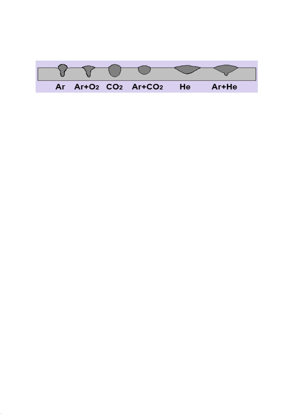
Penetration Profiles
Base Material considerations
Base material type or classification
Base material thickness
Joint design
Welding position
Metal transfer mode
Spray transfer
Globular transfer
Dip transfer
Pulsed current transfer
Quality aspect of the finished weld
Mechanical and chemical requirement
Surface finish
Penetration
Economics of the weld
Clean up costs (acceptable level of spatter)
Welding travel speed
Flow rate of shielding gas
Cost of shielding gas
Different shielding gas formulations produce quite different and significant changes to the penetration
profile of the weld.
Selecting the Correct Shielding Gas
Carbon Steel - Low content CO2 Mixtures
Most shielding gases are based on the argon/carbon dioxide/oxygen system for welding carbon steels.
Low content CO2 mixture (1-7% CO2) produce welds with a “Wine Glass” penetration profile similar to
that produced by pure argon, along with a very stable arc and low spatter levels.
Due to these mixtures having a relatively low heat input, fusion defects and porosity can occur when
welding heavy sections due to the penetration profile, low fluidity and the rapid freezing of the weld
pool.
Carbon Steel – Intermediate content CO2 mixtures
Intermediate content CO2 mixtures (8-15% CO2) produce a higher heat input giving improved
characteristics and broader penetration profile.
These mixtures are more versatile than the low content CO2 mixtures and sound welds can be
produced over a wide range of material thickness.
These mixtures usually produce the most stable welding arc characteristics and are normally the best
general purpose shielding gases for Mild, Carbon and Low Alloy Steels.
High content CO2 mixtures
High content CO2 mixtures (16-23% CO2) allow for further improvements in the fusion characteristics
and the penetration profiles of the weld.
These mixtures are ideally suited for welding heavy sections especially in multi pass situations.
The stiff weld pools cool relatively slowly which aids welding and complete fusion to the weld side
walls.
Any entrapped gas has time to disperse before freezing of the weld pool occurs.
The arc is less stable than with the low content CO2 mixtures which may result in increased spatter
levels.
TitanMig Pulse 270/3500/5000 Operators Manual
Issue. A 0516 29
Page 34

Welding current setting
Wire Diameter(mm)
Welding Current Range(A)
Optimal Current(A)
0.8
50-120
70-100
1.0
70-180
80-120
1.2
80-350
100-200
Welding Mode
Welding with thin wire
Welding with thick wire
Welding with thick wire
under high current
Gas Flow(L/m)
5~15
15~20
20~2
Set the welding current after the above preparation. Short circuiting transfer is mainly fit for electrode
wires of diameter 0.6~1.2mm. As a guide for short circuit welding set the welding current according to
the table below.
Welding speed selecting
The welding quality and productivity should be taken into consideration for the selecting of welding speed.
In the case that the welding speed increases, it weakens the protection effect and quickens the cooling. As
a consequence, it is not good for weld bead shaping. In the event that the speed is too slow, the work
piece will be burned through, and a good weld bead will be unavailable. In practical operation, the welding
speed should not exceed 50cm/min.
Wire Stick-out
The increase of the stick-out can improve the productivity, but too long stick-out may lead to excessive
spatter, wire breaking and unstable welding. Generally, the stick-out should be 10 times as the welding
wire diameter.
Shielding Gas flow selection
The protection effect is the primary consideration. Besides, the protection effect of inner-angle welding is
better than that of external-angel welding, so the gas flow in inner-angle welding should be lower. Less or
no shield gas is needed in FCAW. Refer to the table below for the recommended gas flow rates.
TitanMig Pulse 270/3500/5000 Operators Manual
Issue. A 0516 30
Page 35
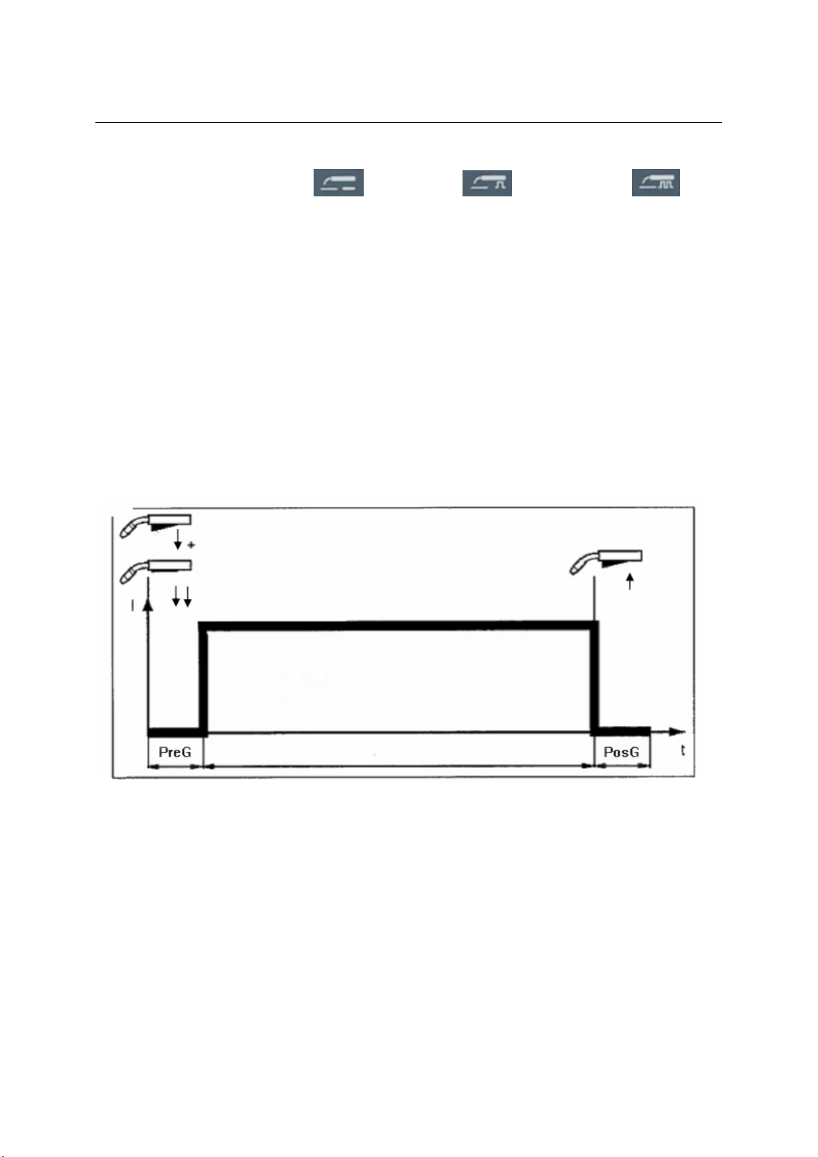
3.1 GMAW (MIG) Welding
Use welding process button to select Synergic Mig or Single Pulse Mig or
Double Pulse Mig welding method. then adjust the other parameters.
Current, wire feed speed and thickness: these three parameters are linked, if you adjust one of them,
the others will be matched automatically due to there is a Highly intelligent expert database in welding
machine.The user just need to select the welding process, operation mode, type of material, wire
diameter and any one of (current, wire speed, thickness), the machine will find the best combinated
parameters from the expert database.
Arc length: the standard arc length in the expert database is (=0), the user could increase or decrease the
arc length according to the welding technology.
Inductance/arc force: the standard inductance in the expert database is 0, the user could increase or
decrease the inductance/arc force. And the inductance perform different functions in different welding
methods. MIG/MAG: 0: soft arc, small splash Pulse MIG: 0:increase the droplet transfer force
Type of material: the user could select the suitable type of material according to the base metal dand
welding wire, details in section 4.10 (expert database of MIG, PULSE MIG, & DOUBLE PULSE MIG).
Wire diameter: setting the diameter directly according to the actual used welding wire.
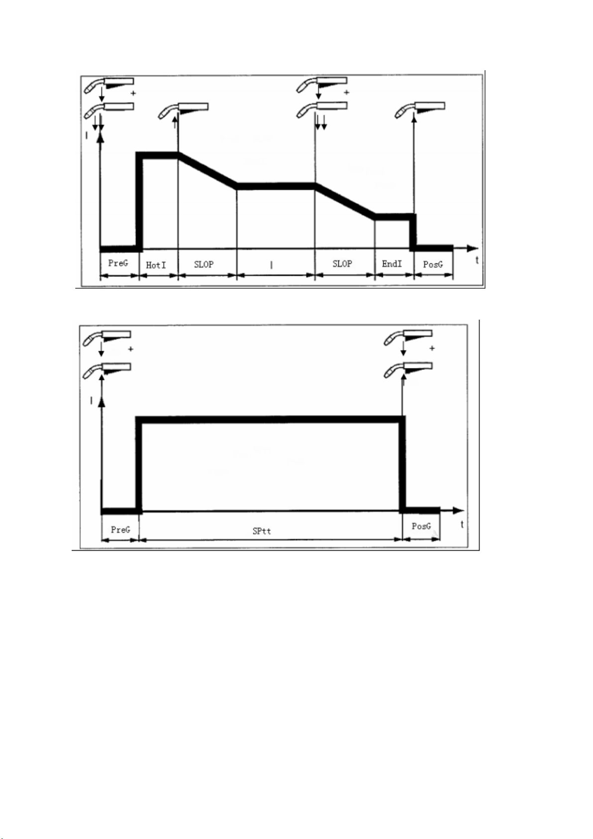
Operation mode: there are 5 kinds of torch operation mode as following diagram:
2T
TitanMig Pulse 270/3500/5000 Operators Manual
Issue. A 0516 31
Page 36
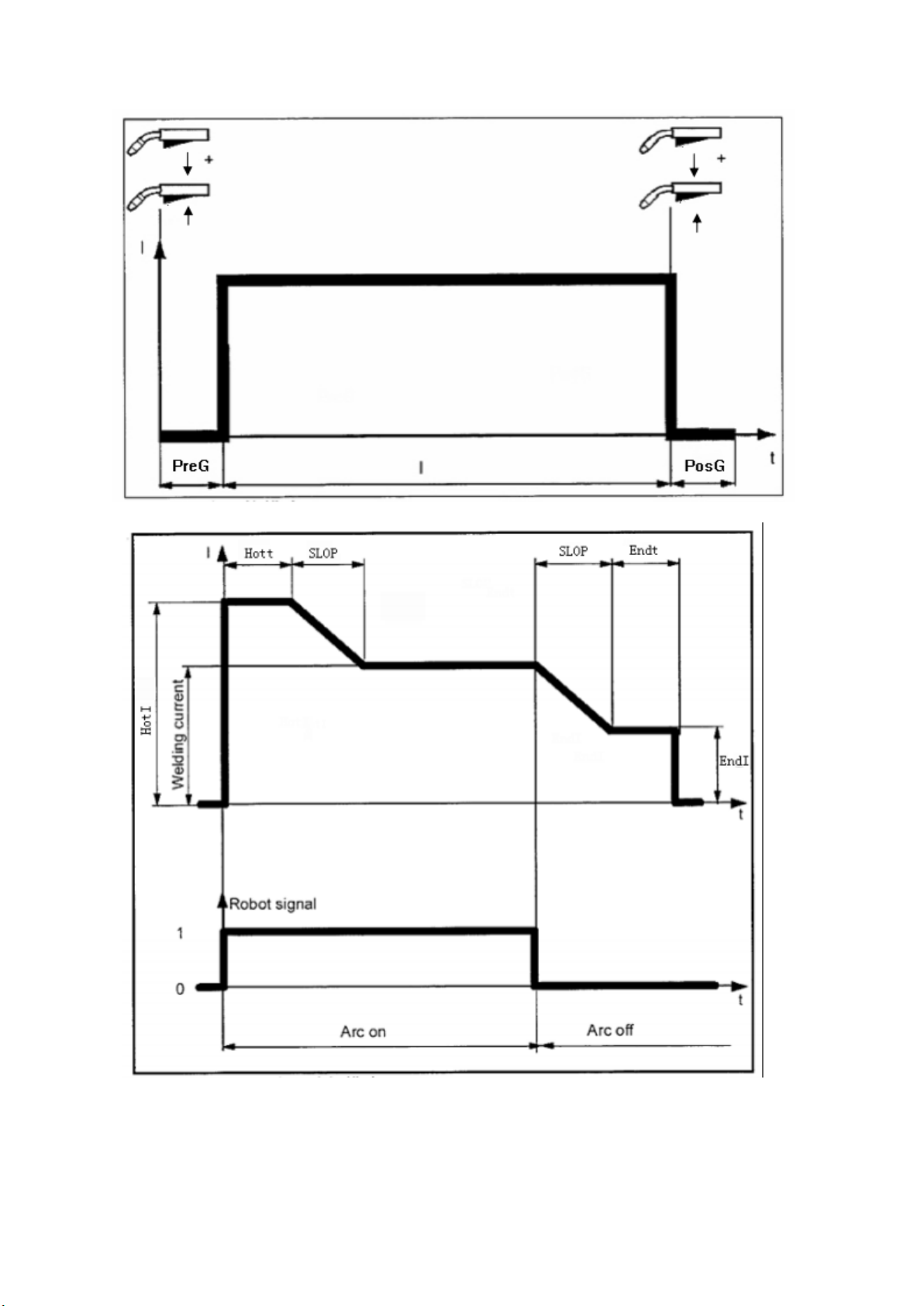
4T
Special 2T
TitanMig Pulse 270/3500/5000 Operators Manual
Issue. A 0516 32
Page 37
Special 4T
Spot Welding
End current(EndI): as figures shown, its function is to fill the crater.
Initial current(HotI) : as figures shown, its function is to increase the heat input when start to weld and
avoid the welding defects during the arc strike.
Burn time: it is to adjust the effect of ball cutting when finish welding.
Spot time(Sptt): the duration of the spot welding.
Initial time(Hott): the duration of the initial current, it is only suitable for S2T.
End time(Endt): the duration of the end current, it is only suitable for S2T.
Slop time(SLOP): the switching time between two currents, such as the initial current and welding current.
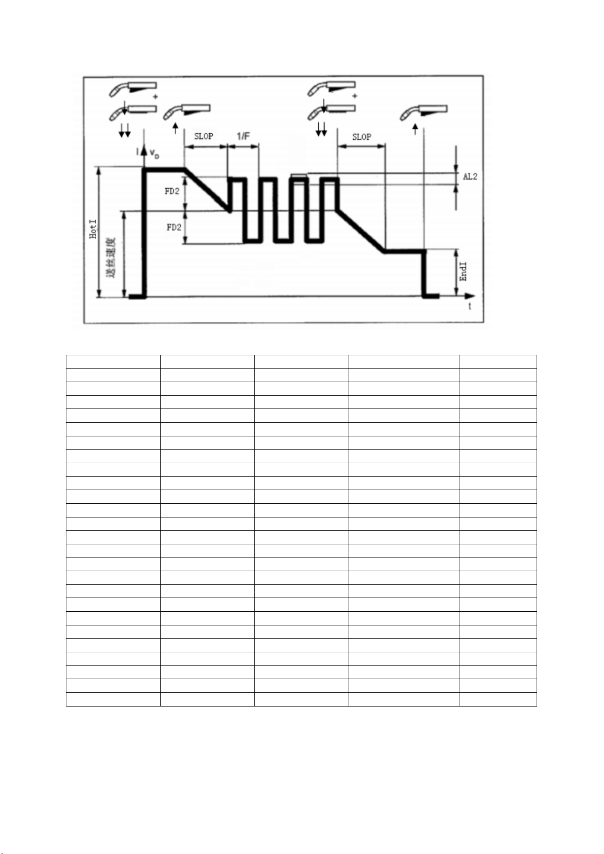
Double pulse frequency (Freq): as figures shown
The arc length of double pulse (AL2): as figures shown, it is the High arc length value of the double pulse
MIG, The lowe arc length decided by corresponding arc in the indicator lamp I
The scope of the double pulse(Fd2) , as below figures shown, it is the rangeability of wire speed for
double pulse.
TitanMig Pulse 270/3500/5000 Operators Manual
Issue. A 0516 33
Page 38
No.
material
AWS specification
Protective Gas
Remark
1
Steel:G3/4 Si
CO2%
2 AlMg4,5Mg
ER5083 H
Ar+50%He
Optional
3
AlSi 5
ER4043
Ar 100%
4 AlMg 5
ER5356
Ar 100%
5 Al99.5
ER1050
Ar 100%
6 AlSi12
ER4047
Ar 100%
Optional
7
CuAl9
ER Cu Al
Ar 100%
8 CuSi3
ER Cu Si
Ar 100%
9 NiCr 21 Mo 9 Nb
ER NiCrMo
Ar 100%
Optional
10
CrNi 18 8 6
ER307
A r 97.5% CO2 2.5%
11
CrNi19 9
ER308
A r 97.5% CO2 2.5%
12
CrNi 22 12
ER 309
A r 97.5% CO2 2.5%
Optional
13
CrNi 25 20
ER 310
A r 97.5% CO2 2.5%
Optional
14
CrNi 19 12 3
ER 316
A r 97.5% CO2 2.5%
Optional
15
CrNi 13 4
ER 410
A r 97.5% CO2 2.5%
Optional
16
CrNb 16
ER 430
A r 97.5% CO2 2.5%
Optional
17
CrNi 22 9
ER 2209
Ar 82% CO2 18%
Optional
18
CrNi 19 12 3
ER 316
Ar 82% CO2 18%
Optional
19
CrNi 13 4
ER 410
Ar 82% CO2 18%
Optional
20
CrNi Flux cored
Ar 82% CO2 18%
21
Rutil Flux cored
Ar 82% CO2 18%
22
Basic Flux cored
Ar 82% CO2 18%
23
Metal Flux core
Ar 82% CO2 18%
24
Steel:G 3/4 Si 1
Ar 82% CO2 18%
25
Hard facing
Ar 82% CO2 18%
Optional
The expert database for MIG, Pulse MIG and double pulse MIG
TitanMig Pulse 270/3500/5000 Operators Manual
Issue. A 0516 34
Page 39
Work piece preparation
Joint type
Groove shape
Weld shape
Metal thickness
[mm]
Work piece
spacing [mm]
Square butt
joint
single sided
up to 1,5
from 1,5
0 to 2
Square butt
joint
double sided
2 to 4
up to 2
V – butt joint
3 to 6
up to 1
3 to 6
up to 1
Square T - joint
single sided
from 0,6
-
Square T - joint
double sided
from 0,6
-
Lap joint
0,6 to 1,5
-
Edge joint
from 1
-
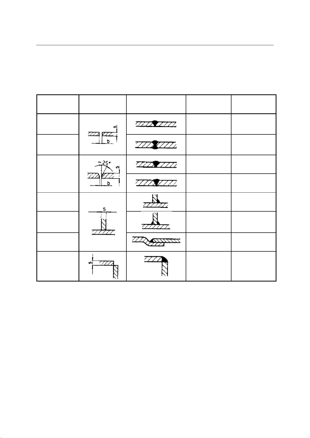
Welding joint describes the welding spot and exact position of work pieces to be welded together. Work
piece preparation, groove form and width, material type and thickness, together with certain welding
technique all determine joint type.
Around the groove work pieces should be dry and clean, free of rust, metallic coating, dirt, colour or
grease.
TitanMig Pulse 270/3500/5000 Operators Manual
Issue. A 0516 35
Page 40
Positioning the welding torch
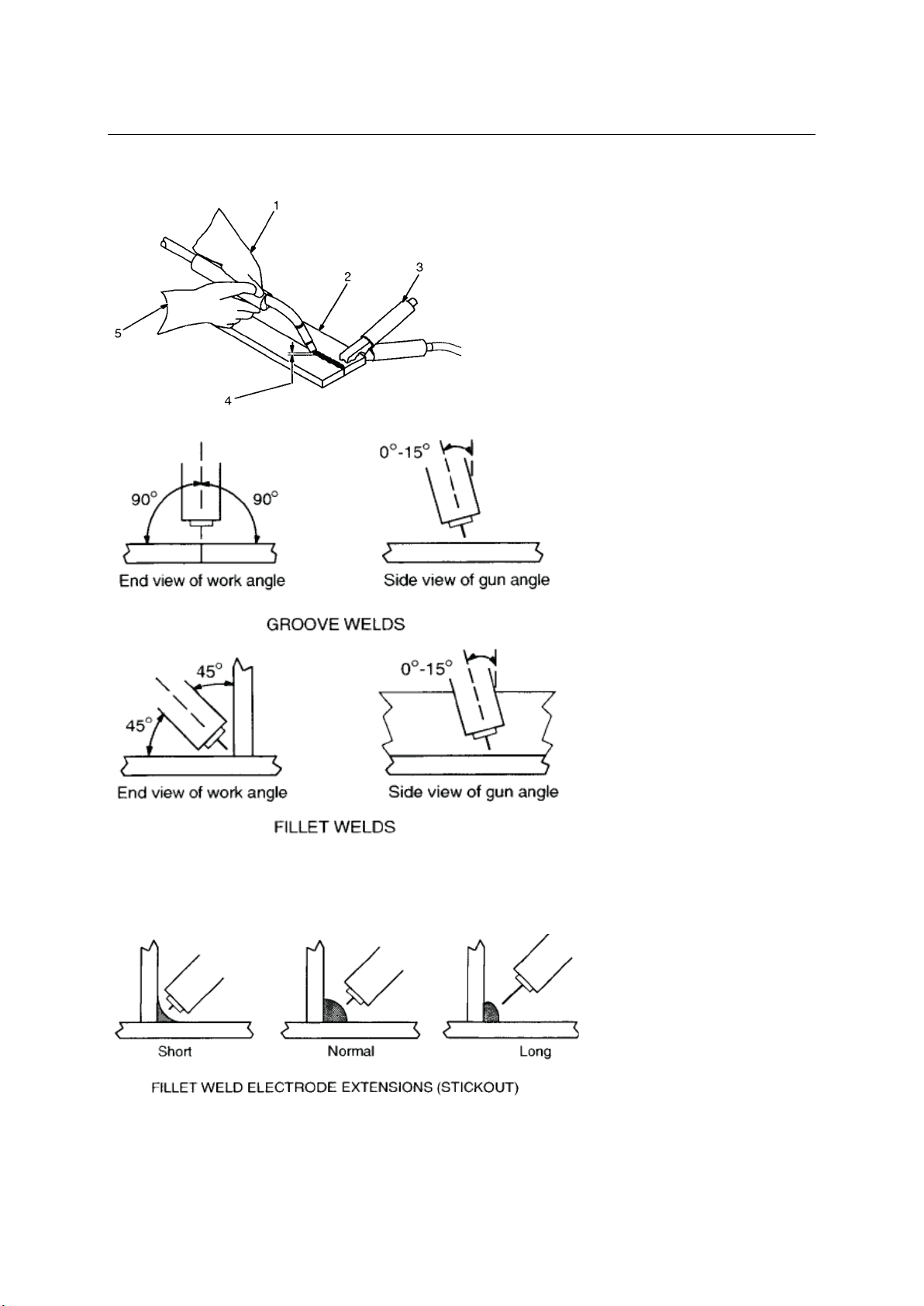
Welding wire is energised when the torch button is pressed. Lower your helmet first and then press the
trigger. Wire should be around ½ in past end of nozzle, and tip of wire positioned correctly on seam.
1…….. Hold torch and control trigger with one
hand
2…….. Work piece
3…….. Earth clamp
4…….. Electrode extension (Stick out) ¼ to ½ in
5…….. Cradle torch with the other hand and
rest it on work piece
Heat distribution and weld
material flow are specific for
groove welds and fillet welds.
Optimal torch position differs
from one to another.
Weld bead shape differs
depending on electrode
extension when welding fillet
welds.
TitanMig Pulse 270/3500/5000 Operators Manual
Issue. A 0516 36
Page 41
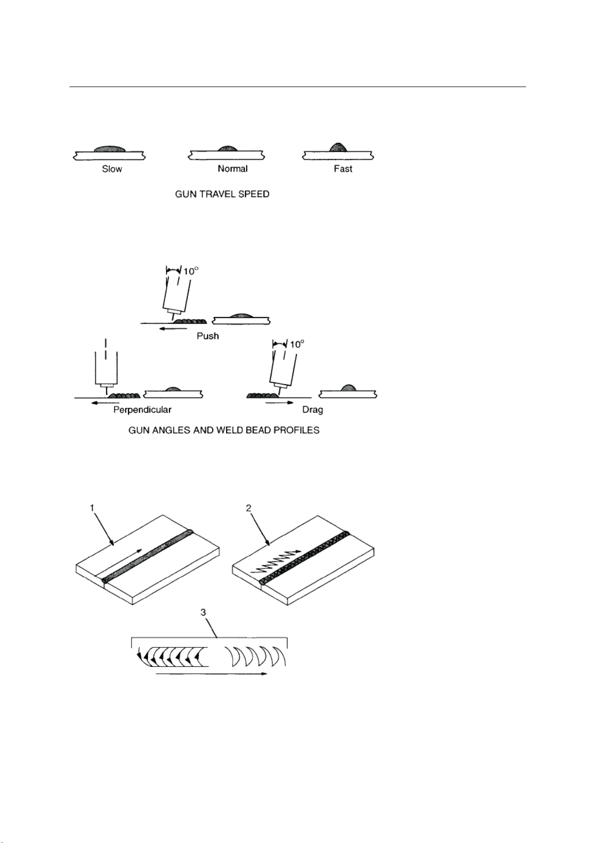
Gun movement during welding
Weld bead shape as well as penetration and overall joint quality are affected by torch angle, direction of
travel, electrode extension, travel speed, thickness of base material, wire feed speed, and voltage.
varies with torch travel speed.
For adequate penetration to
be achieved welding source
must provide more power at
Using constant parameters welding material deposit and penetration
1…….. Stringer bead – steady movement along seam
2…….. Wave bead – side to side movement along seam
higher speeds.
Dragging the torch results in
deeper penetration and
narrower weld. Arc strength
prevents slag to enter the
molten material.
When pushing the torch
penetration will be shallower
and the weld wider. This
movement is suitable for thin
plates because of smaller heat
input.
3…….. Wave patterns
Use weave patterns to cover a
wide area in one pass of
electrode.
Normally a single stringer bead
is satisfactory for most narrow
groove weld joints. However for
wide groove weld joints or
bridging across gaps, a weave
bead or multiple stringer beads
work better.
TitanMig Pulse 270/3500/5000 Operators Manual
Issue. A 0516 37
Page 42
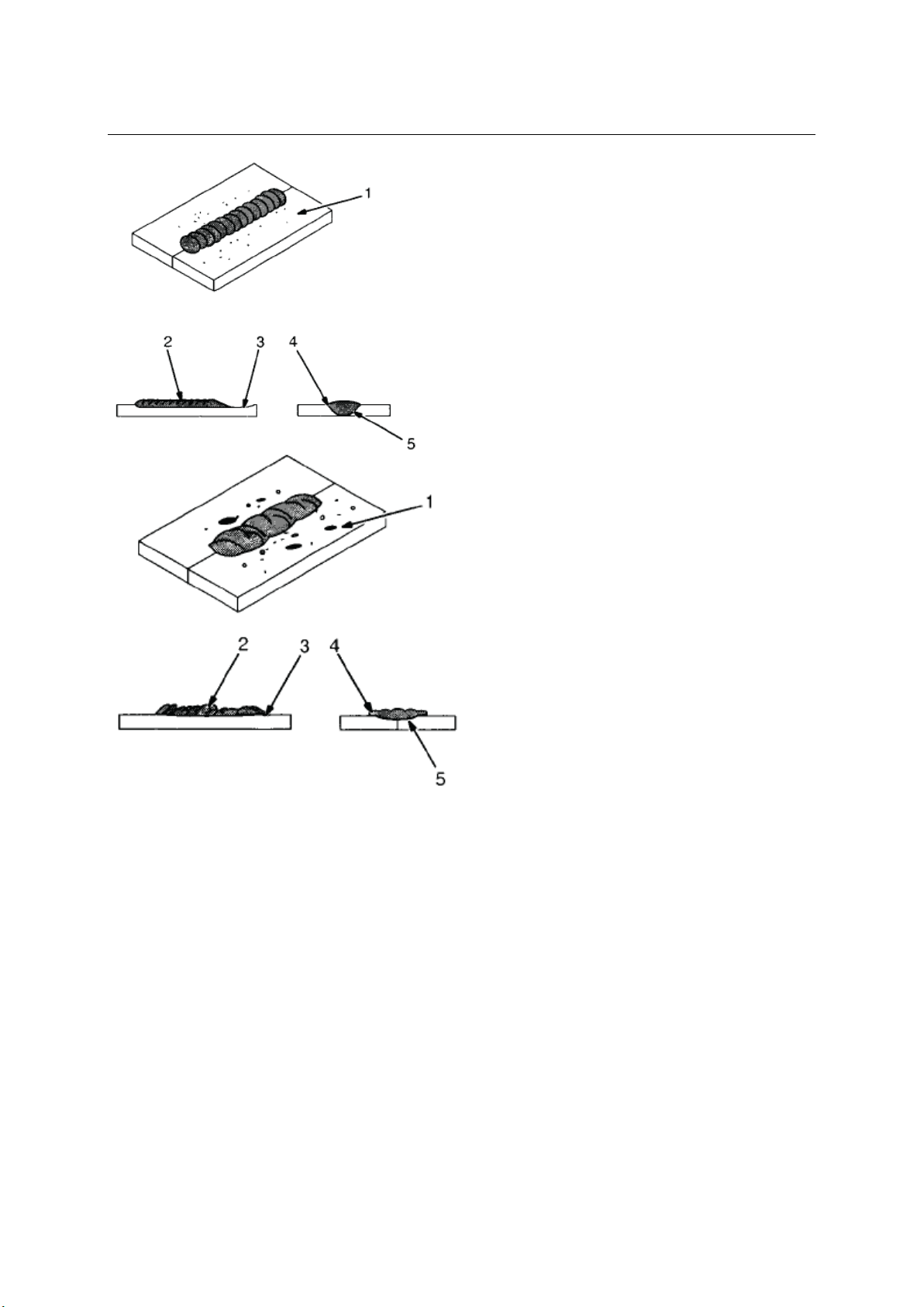
Welding results and troubleshooting
GOOD WELD BEAD
1…….. Fine spatter
2…….. Uniform bead
3…….. Moderate crater during welding
4…….. No overlap
5…….. Good penetration into base material
POOR WELD BEAD
1…….. Large spatter deposits
2…….. Rough, uneven bead
3…….. Slight crater during welding
4…….. Bad overlap
5…….. Poor penetration
TitanMig Pulse 270/3500/5000 Operators Manual
Issue. A 0516 38
Page 43
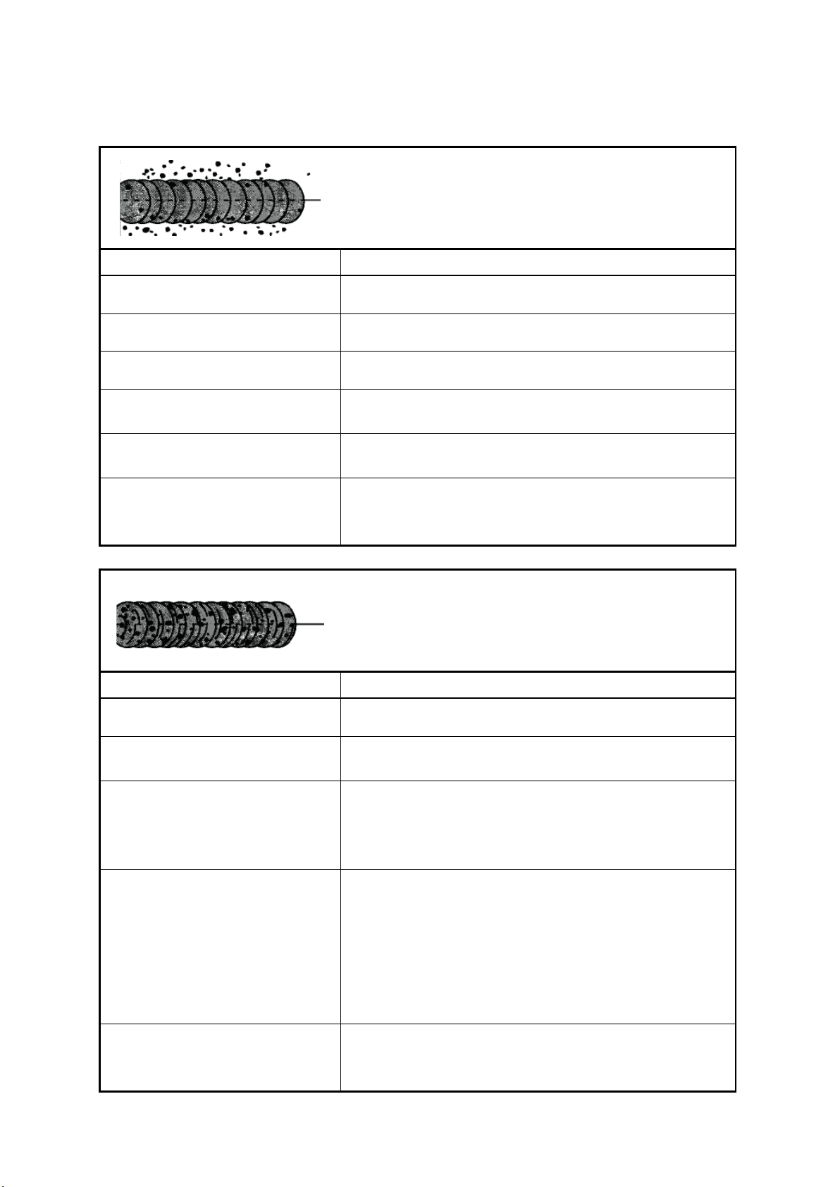
Excessive spatter
Scattering of molten metal particles that cool to solid near
weld bead.
Possible causes
Corrective actions
Wire feed speed too high.
Select lower wire feed speed.
Voltage too high.
Select lower voltage.
Electrode extension too long.
Use shorter electrode extension.
Work piece dirty.
Remove all grease, oil, moisture, rust, paint, undercoating, and
dirt from work surface before welding.
Insufficient shielding gas at arc.
Increase flow of shielding gas at regulator and/or prevent
drafts near welding arc.
Dirty welding wire.
Use clean, dry welding wire.
Eliminate pickup of oil or lubricant on welding wire from
feeder or liner.
Porosity
Small cavities or holes resulting from gas pockets in weld
material.
Possible causes
Corrective actions
Wrong gas.
Use welding grade shielding gas; change to different gas.
Welding wire extends too far out of
nozzle.
Be sure welding wire extends no more than ½ in beyond
nozzle.
Work piece dirty.
Remove all grease, oil, moisture, rust, paint, undercoating, and
dirt from work surface before welding.
Use a highly deoxidising welding wire (contact supplier).
Insufficient shielding gas at arc.
Increase flow of shielding gas at regulator and/or prevent
drafts near welding arc.
Remove spatter from gun nozzle.
Check gas hoses for leaks.
Place nozzle ¼ to ½ in from work piece.
Hold gun near bead at end of weld until molten metal
solidifies.
Dirty welding wire.
Use clean, dry welding wire.
Eliminate pickup of oil or lubricant on welding wire from
feeder or liner.
Page 44
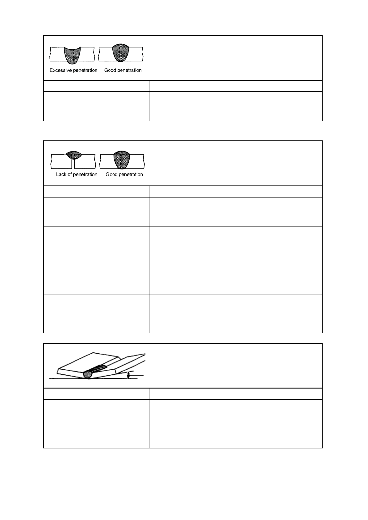
Excessive penetration
Weld metal melting through base metal and hanging
underneath it.
Possible causes
Corrective actions
Excessive heat input.
Select lower voltage range and reduce wire feed speed.
Increase travel speed.
Lack of penetration
Shallow fusion between weld metal and base metal.
Possible causes
Corrective actions
Improper joint preparation.
Material too thick. Joint preparation and design must provide
access to bottom of groove while maintaining correct welding
wire extension and arc characteristics.
Improper welding technique.
Maintain normal gun angle of 0 to 15 degrees to achieve
maximum penetration.
Keep arc on leading edge of weld puddle.
Be sure welding wire extends no more than ½ in beyond
nozzle.
Insufficient heat input.
Select higher wire feed speed and/or select higher voltage
range.
Reduce travel speed.
Distortion
Contraction of weld metal during welding that forces base
metal to move.
Possible causes
Corrective actions
Excessive heat input.
Select lower voltage range and reduce wire feed speed.
Increase travel speed.
Use restraint (clamp) to hold base metal in position.
Make tack welds along joint before starting welding operation.
Weld in small segments and allow cooling between welds.
TitanMig Pulse 2700/3500/5000 Operators Manual
Issue. A 0516 40
Page 45
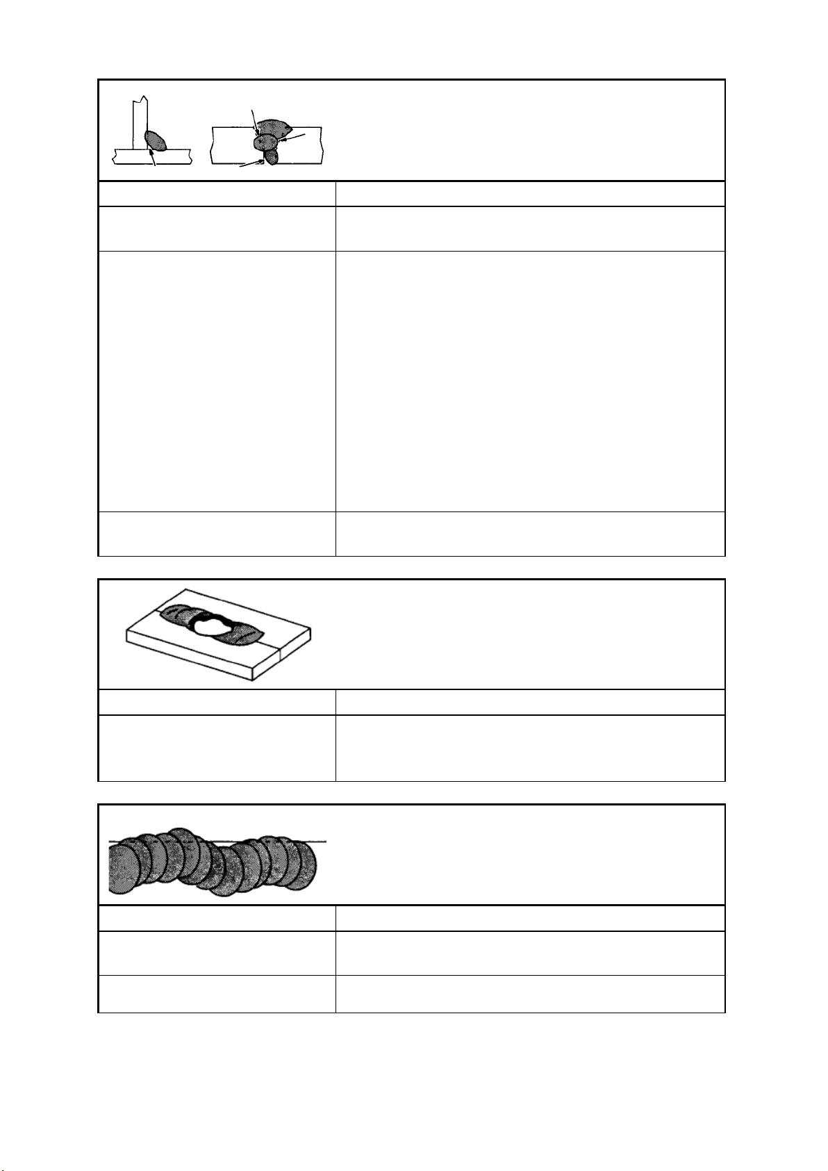
Incomplete fusion
Failure of weld metal to fuse completely with
base metal or a preceding weld bead.
Possible causes
Corrective actions
Work piece dirty.
Remove all grease, oil, moisture, rust, paint, undercoating, and
dirt from work surface before welding.
Improper welding technique.
Place stringer bead in correct location(s) at joint during
welding.
Adjust work angle or widen groove to access bottom during
welding.
Momentarily hold arc on groove side walls when using weaving
technique.
Keep arc on leading edge of weld puddle.
Use correct gun angle of 0 to 15 degrees.
Insufficient heat input.
Select higher wire feed speed and/or select higher voltage
range.
Burn-through
Weld metal melting completely through base metal resulting in
holes where no metal remains.
Possible causes
Corrective actions
Excessive heat input.
Select lower voltage range and reduce wire feed speed.
Increase and/or maintain steady travel speed.
Incomplete fusion
Weld metal that is not parallel and does not cover
joint formed by base metal.
Possible causes
Corrective actions
Welding wire extends too far out of
nozzle.
Be sure welding wire extends no more than ½ in beyond
nozzle.
Unsteady hand.
Support hand on solid surface or use two hands.
TitanMig Pulse 2700/3500/5000 Operators Manual
Issue. A 0516 41
Page 46
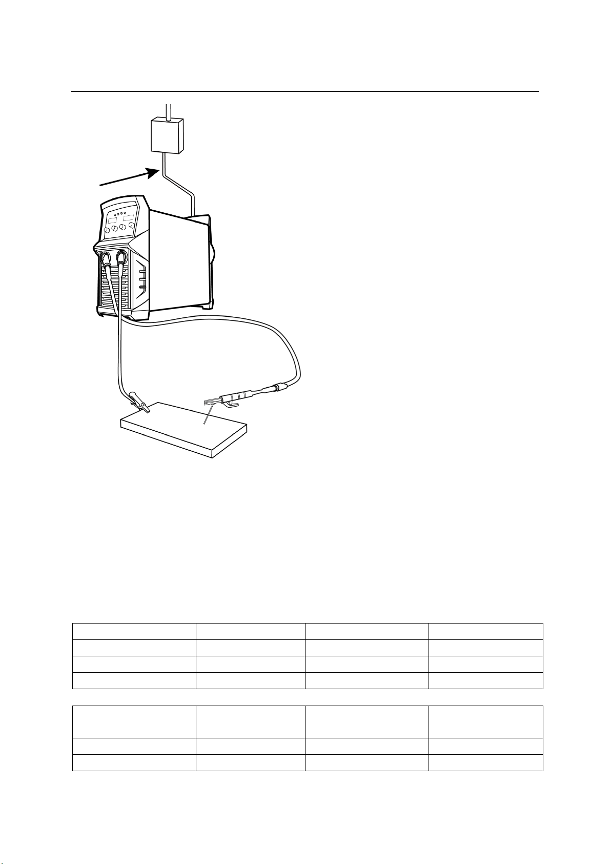
3.2 MMAW (Stick/MMA) Welding
Electrode Diameter(mm)
Welding Current(A)
Electrode Diameter(mm)
Welding Current(A)
2.0
40-60
4.0
130-180
2.5
60-95
5.0
180-220
3.2
95-130
6.0
220-260
Average Thickness of
Material (mm)
Suggested Electrode
Diameter (mm)
Average Thickness of
Material (mm)
Suggested Electrode
Diameter (mm)
1.0-2.0
2.5
5.0-8.0
4.0
2.0-5.0
3.2
8.0 >
5.0
Insert the cable plug with electrode holder into the
“+” socket on the front panel of the welding
machine, and tighten it clockwise.
Insert the cable plug of the work return lead into
the “-” socket on the front panel of the welding
machine, and tighten it clockwise
After connecting the welding leads as detailed you will need to switch the power switch on the
back panel to “ON”
Select MMA by switching to the MMA welding mode. There is voltage output at both output
terminals.
Set the amperage on the machine suitable for the electrode being used. Ensure you check that
you have the electrode polarity correct.
Please see below a guide to amperages required.
TitanMig Pulse 2700/3500/5000 Operators Manual
Issue. A 0516 42
Page 47

3.2 MMAW (Stick/MMA) Welding
1) Use welding process buttons to select MMA welding method.
2) Turn left side to alter A to adjust welding current
3) Turn right side to set the arc force.
4) Start welding
All the parameters in steps 1.2.3 could be saved automatically when the machine is working and
remain the same even if the machine is killed halfway. The MMA welding has seven adjustable
parameters:
Current: The range (10A ~ rated current) is welding current, please choose the proper Knob A Knob
M MMA 35 current according to welding technology.
Arc force: 1 ~ 100, refers to the slop of current rise in the process of short circuit. It should be settled
based on electrode diameter, set current value and welding procedure requirements. The stronger arc
force, the faster droplets, the less sticking. However, too strong arc force would increase splashes. The
weaker arc force, the lower splashes, the better welding seam, but sometimes, people feel that the
arc is soft or cause sticking. So the arc force should be increased when use wide electrode rod (4mm)
with small current (120A). The arc force should be 10~50 in general.
Hot starting arc current (HotI) : 0 ~ 100%, 20 refers to Hot starting arc current = welding current + 20%
* welding current. The hot starting arc time (Hott) : 0 ~ 1.5 s, refers to the duration of Hot starting arc
time. In order to strike arc successfully, the welder would output a high current as striking current, the
duration of striking current is determined by the ignition time. The two parameters should be set
according to the welding situation, the higher striking current and the longer duration, the easier
ignition. But for sheet welding, the striking current and duration can not be too high and too long, so
as not to burn the workpiece. In general, the striking current should be 1.5 times of welding current,
and striking time is 0.02~0.05s.
External characteristics (Slop): In order to fit different kinds of electrodes, the MMA welding machine
own adjustable external characteristics curve. Adjust the SLOP to change external characteristics. CC:
constant-current characteristic. Arcing current is constant, independent of the welding voltage.
Adapted to acid electrode, basic electrode and groove weld.. 1-20 is decreasing characteristic of
adjustable slope, the lower the voltage, the greater the current. 20 represents the voltage drops each
1V, the current increases 20A. Adapted to the cellulose electrodes. CP: Constant power characteristics:
Output power (I × V) remains the same, especially for cellulose electrodes.
Arc-break adjustment: It is for snapping the arc easily when intermittent welding. It can be set as
30V、40V、50V、 60V,The greater the value, the more difficult to pull off the arc, the parameter should
be off when continuous welding.
Anti-sticking function (Felt) When it is on, it can prevent red and failure electrodes caused by
striking. The machine would stop till the striky electrode is away from workpiece. Then the machine
would continue to work.
VRD function (VRD) 36 There are ON and OFF available for VRD function. When it is ON, the main
circuit would not work under welder not welding. Only output less than 12V voltage. It can not only
avoid no-load voltage injury, but also save electrical energy, reduce noise and increase the life-span.
TitanMig Pulse 2700/3500/5000 Operators Manual
Issue. A 0516 43
Page 48
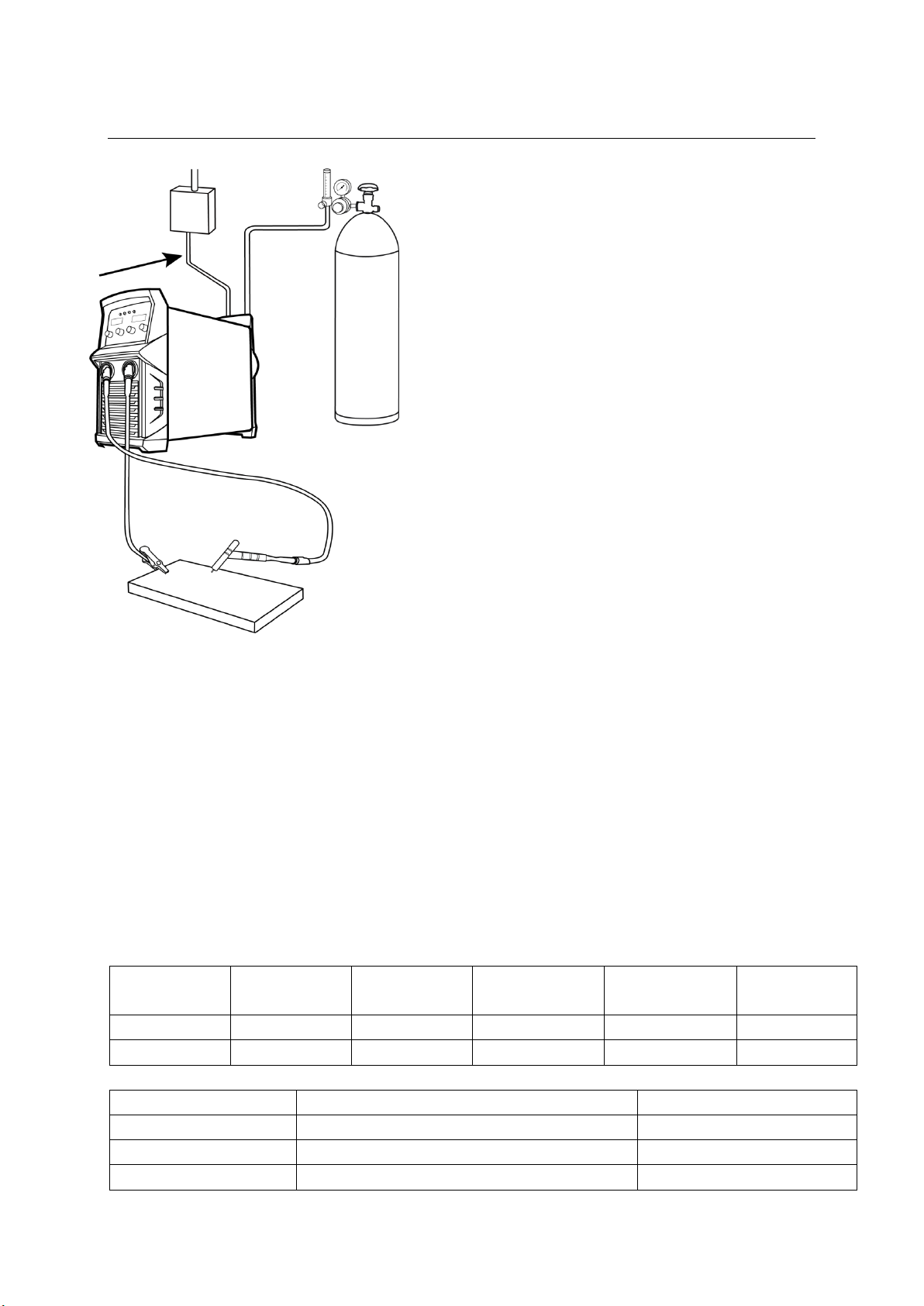
3.3 GTAW (TIG) Welding
Electrode
Diameter(mm)
Welding
Current(A)
Gas Nozzle
Diameter (mm)
Electrode
Diameter(mm)
Welding
Current(A)
Gas Nozzle
Diameter(mm)
1.0
15-80
8.0
2.4
150-250
9.5
1.6
70-150
9.5
3.2
250-400
11.0
Type
Mode
Colour
Thoriated 2%
DC welding of steel, stainless steel and copper
Red
Ceriated
DC welding of steel, stainless steel and copper
Grey
Lanthanated 1.5%
DC welding of steel, stainless steel and copper
Gold
Insert the cable plug with the work clamp into the “+”
socket on the front panel of the welding machine, and
tighten it clockwise.
Insert the cables plug of the TIG torch into the “-” socket on
the front panel of the machine and tighten clockwise.
Connect the gas hose to the regulator / flowmeter located
on the shield gas cylinder.
Open the valve on the TIG torch and “scratch” the electrode
on the work piece to start the arc
Connect the TIG torch leads as detailed above. Ensure that a suitable inert gas supply is
connected.
Switch the power switch on the back panel to “ON”
Select the TIG welding mode using the selector switch.
There is voltage output at both output terminals.
After the parameters are set appropriately, open the gas valve of the cylinder, the gas valve on the
torch and adjust the gas regulator to obtain the desired flow rate.
The arc will start when the tungsten electrode touches the work piece and is lifted off after
touching by between 2-4mm
The arc will cease when the electrode (torch) is moved away from the work area
TIG guides
The recommended size of tungsten/nozzle to be used can be selected from the table below
Electrode type
TitanMig Pulse 2700/3500/5000 Operators Manual
Issue. A 0516 44
Page 49
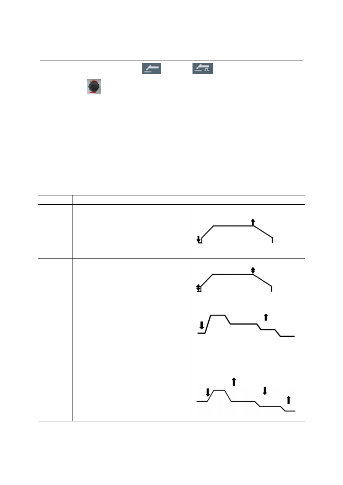
method
operation mode
TIG torch switch & Current Curve
2T
①Press the on/off button, arc strike and
upslope ②Loose the on/off button, down
slop and arc quench ③If press the on/off
button again before arc quenching, it will
continue up sloping to the settled parameter,
and turn to ②
4T
① Press the on/off button, arc strike and
upslope ②Re-press the on/off button, down
slop and arc quench
Special 2T
① Press the on/off button, arc strike and
upslope to initial current HotI ②Last Hott
time, then down slope to the set current
③Loose the on/off button, down slop to end
current EndI ④Last Endt time, then quench
arc
Special 4T
① Press the on/off button, arc strike and
upslope to initial current HotI ② Loose the
on/off button, down slop to set current
③Re-press the on/off button ,down slop to
end current EndI ④Loose the on/off button,
quench arc
3.3 GTAW (TIG) Welding
1) Use welding process button to select Lift-TIG or Pulse Lift-TIG welding method.
2) Turn left side to alter A to adjust welding current
3) Select the suitable operation mode by the welding process button.
4) Adjust the gas-flow rate of the cylinder after pressing the gas check button.
5) Start welding
All the parameters in steps 1.2.3 could be saved automatically when the machine is working and
remain the same even if the machine is killed halfway.
Current: 2~Rated Current The welding current of DC TIG and Spot TIG, the peak current of the Pulse
TIG, please adjust the suitable current according to the welding technology.
Operation Mode: TIG operation is the operation mode, which use the torch switch to control the
welding current during working of DC TIG and PULSE TIG. There are 5 ways for TIG welding, including
2T, 4T, S2T, S4T and Spot Welding, The TIG welding ways should be selected according to the technical
requirements and the operation habit of the operator.
TitanMig Pulse 2700/3500/5000 Operators Manual
Issue. A 0516 45
Page 50
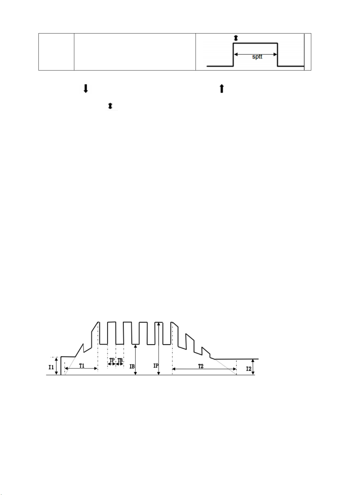
Spot
welding
① Press the on/off button, strike arc to set
value ②Last spot time, quench arc.
Table 4.1 the operation mode of TIG welding
Note: graphic means pressing on/off button of the TIG torch, means loosing the on/off
button of the TIG torch, means pressing the on/off button once (press, then loose)
Upslope time(SLPU): 0~15s The upslope time means the time, which the current from 0 to set current, it
should be set according to the technological requirements
Downslope time(SLPD):0~15s The downslope time means the time, which the current from the set
current to 0, it should be set according to the technological requirements
Arc strike mode(HF): the welder provide two arc strike modes including lift (HF) arc strike and contact arc
strike.
End current(EndI):0~200%, it means the percent of the set current, it is used for filling the crater.
Initial current(HotI):0~200%, it means the percent of the set current. The initial current is the current
after arc ignition; it should be set according to the technological requirements. The higher initial current,
the easier arc striking, but it is not suggest to use when welding the sheet metal. Otherwise, it will burn
out the workpiece easily. After ignition arc under some operation mode, the current should keep the
initial current, in order to heat up the workpiece or lighting.
Initial time (Hott): it means the last time of the initial current, it is only valid in the S2T.
End time (Endt): it means the duration of the end current, it is only valid in the S2T.
Spot time: 0.1~2s Spot welding time is the time of the SPOT TIG; it should be confirmed according to the
technological requirements.
Base current: it is the base current of the PULSE TIG, the peak current is the set current
Duty ratio: it is the ratio of the peak time and cycle in the Pulse TIG.
Frequency: it is the frequency of the pulse TIG. These three parameters are for the PULSE TIG only, see the
diagram below:
In the figure the I1 is initial current, IB is base current, IP is peak current(set current), I2 is end current. T1
is upslope time, T2 is downslope time. TP is the duration of the peak current, TB is the duration of the
base current, TP+TB is the pulse cycle, the pulse frequency is the c reciprocal of the cycle: 1/(TP+TB), the
duty ratio is the percentage of the duration of peak current in the pulse cycle: 100*TP/(TP+TB), changing
the pulse frequency and duty ratio could adjust the TP and TB value.
TitanMig Pulse 2700/3500/5000 Operators Manual
Issue. A 0516 46
Current curve of PULSE TIG
Page 51
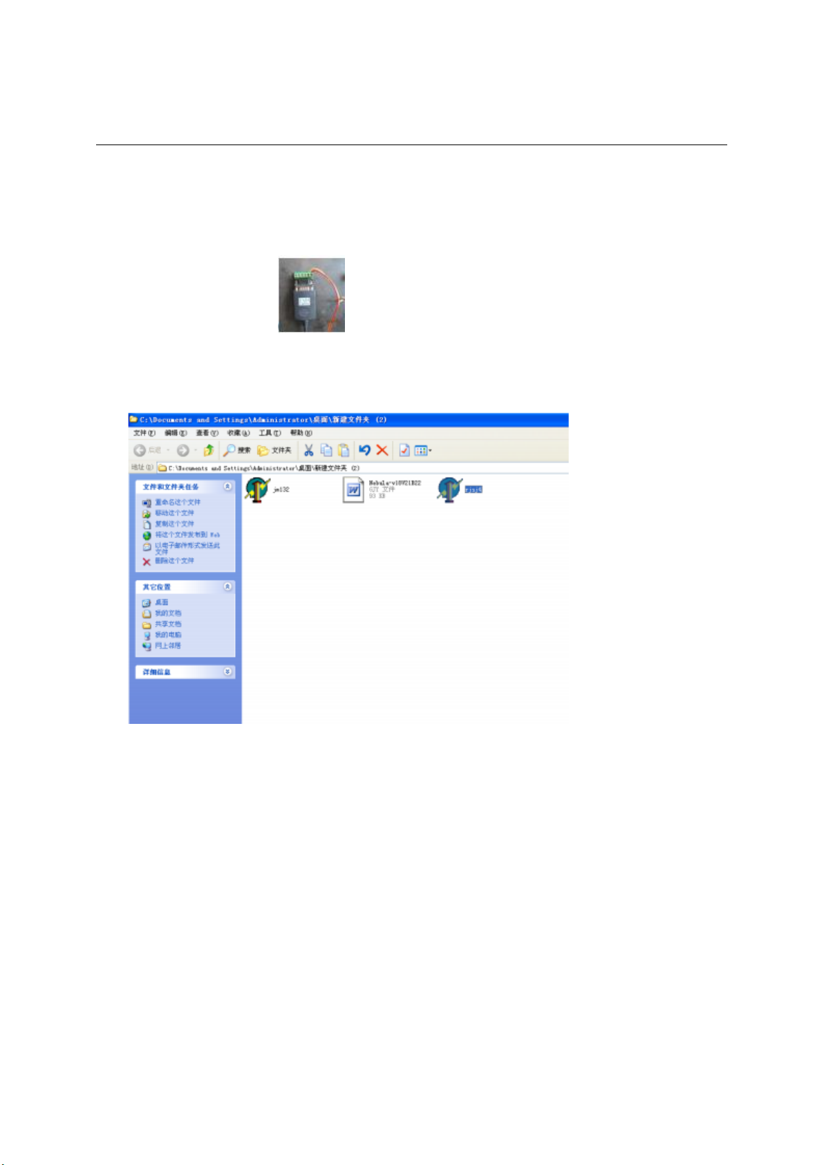
3.4 Software Upgrade
It is the most important advantage that the software can be upgraded for digital welding machines. And
the welding performance can be improved, add and change the function by upgrading software. It is very
easy to operate. The steps are as following:
1) Insert the USB of UT-850 to computer, another side to the welding machine.
2) Turn on the computer and welding machine.
3) Run the rjsj4. exe in the computer as following(a~k)
A. Double click “rjsj4”
TitanMig Pulse 2700/3500/5000 Operators Manual
Issue. A 0516 47
Page 52
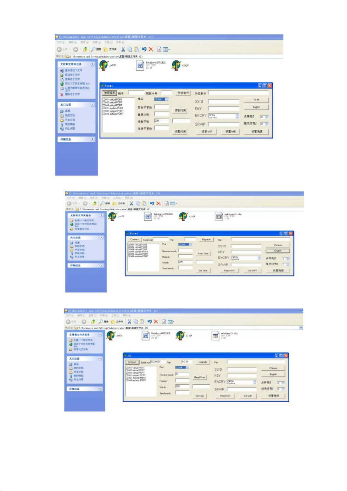
B. Choose “English”
C. Click “Connect”
D. Double click “jm132”
TitanMig Pulse 2700/3500/5000 Operators Manual
Issue. A 0516 48
Page 53
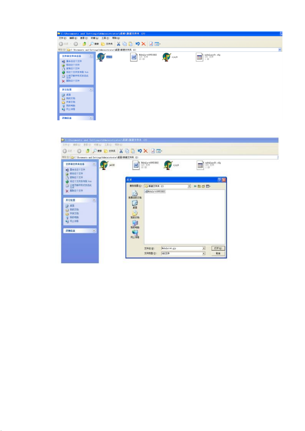
TitanMig Pulse 2700/3500/5000 Operators Manual
Issue. A 0516 49
Page 54
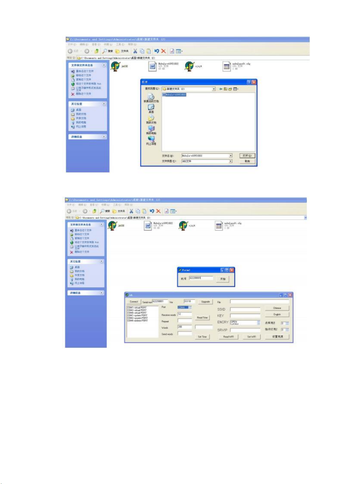
E. Copy and paste the “Serial Number” into “Form1”
F. Click the button “Start”
TitanMig Pulse 2700/3500/5000 Operators Manual
Issue. A 0516 50
Page 55
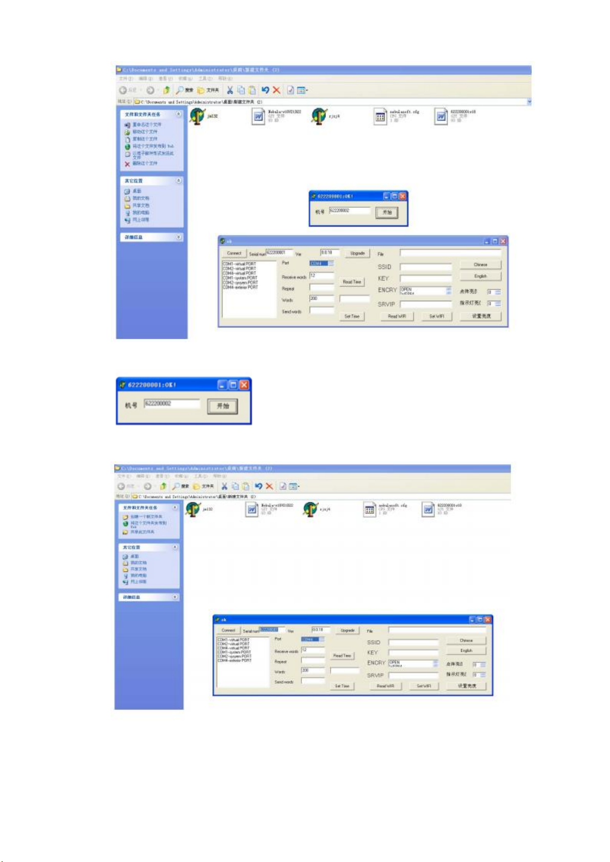
G. When you can see “”OK!”, close the small window
H. Click the “Upgrade”
I. Choose the document
TitanMig Pulse 2700/3500/5000 Operators Manual
Issue. A 0516 51
Page 56
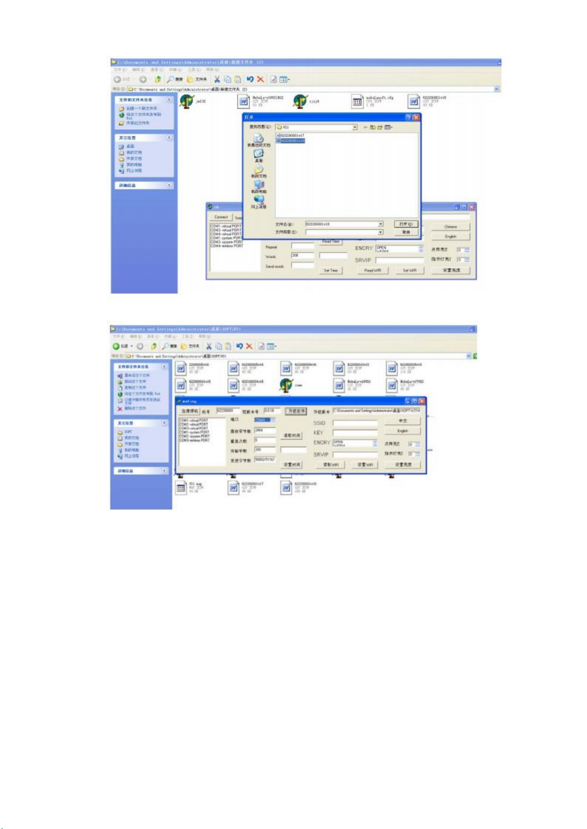
J. Now data has being transmitted.
K. k, Complete
TitanMig Pulse 2700/3500/5000 Operators Manual
Issue. A 0516 52
Page 57
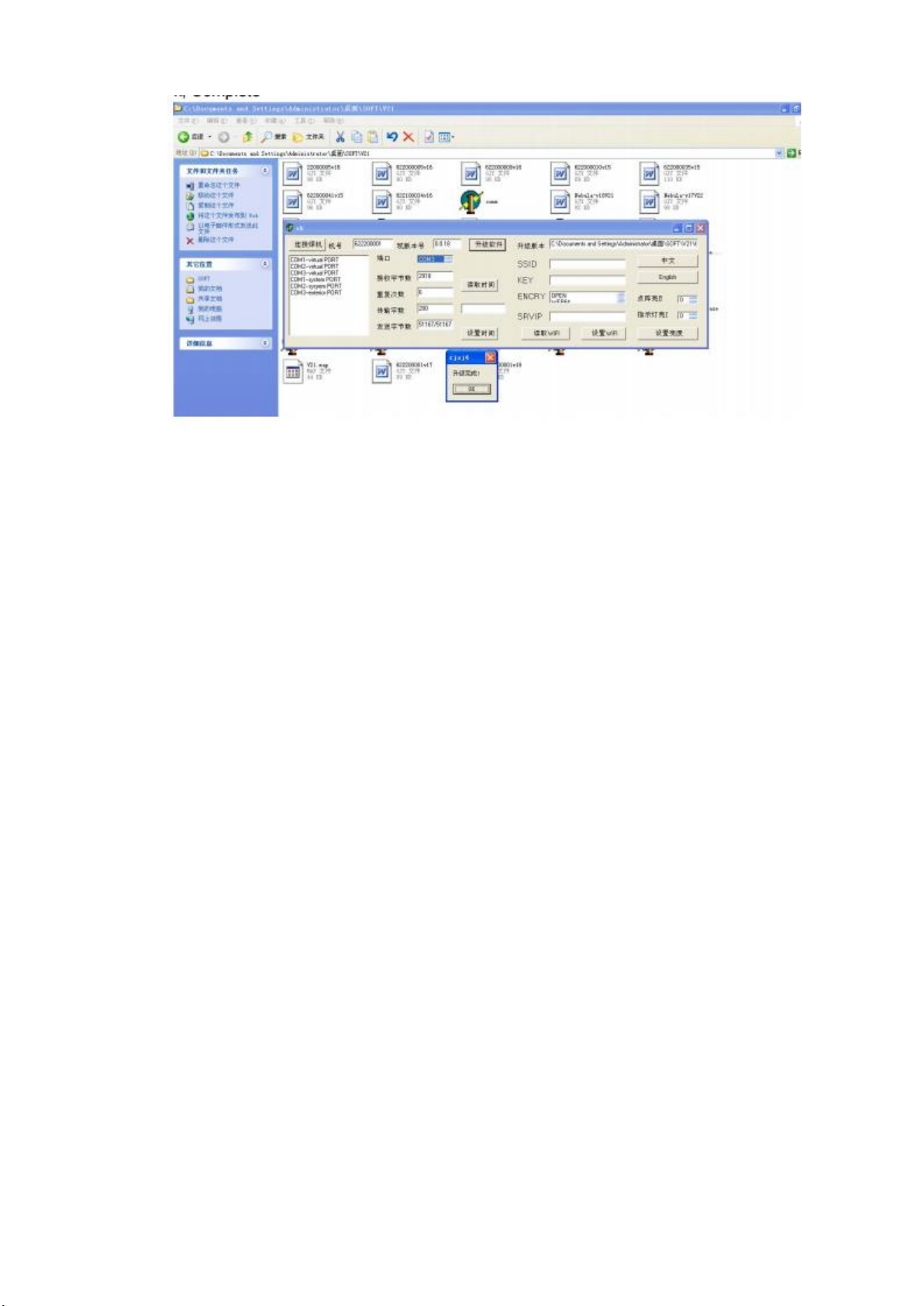
If there’s something wrong with connecting to the welding machine, the reasons may be following:
1. Disconnection or short circuit of the cable, two 485 cables are in reverse order, please check
the cables carefully.
2. Something wrong with the USB-RS485 converter, suggest the UT-850 or change new qualified
one.
3. Driver of USB-RS485 is set wrong, need re-install. If fail to upgrade because of power failure
during the process, please restart welding machine, It will check the correctness of software
automatically after each restart, if the software isn’t correct, it cannot work normally but waiting
to upgrade, in this case re-upgrade the software will be OK.
TitanMig Pulse 2700/3500/5000 Operators Manual
Issue. A 0516 53
Page 58
3.5 Add function
TMP series welding machines have preset the welding processes according to user’s requirements
before delivery, if users need to add other welding processes, please replace the softdog or enter
passwords.
Notes: Only the same capacity and type softdog can be used, users cannot change the capacity
of welding machine, otherwise the welding machine may be damages permanently.
Replace softdog: Take off the case of welding machine, find the “CFM” on the PCB1, pull out the
plug with two pins on “CFM” (it’s the softdog),replace a new one.
Enter password: Enter into the menu of start the machine, enter 4 passwords in corresponding
options, save the passwords and then exit. When you restart the welder, new processes have
been added. Details as following steps(a~e).
A. Long press and turn on the switch.
B. Press , Select “More”
C. Turn on the left. You will find Pas 1, Pas 2,Pas 3, Pas4. displayed on LED
D. Turn on the right to make the numbers the same as the codes
E. Press again. The screen would show “Finished”. Turn off the switch.
Note: The softdog and password need to buy from sellers. Please contact the vendor.
TitanMig Pulse 2700/3500/5000 Operators Manual
Issue. A 0516 54
Page 59

4.0 Trouble Shooting
Possible Reason
Suggested Solution
The Welding current is unstable
The pressure arm on the wire feeder is not
properly adjusted
Adjust it to get proper pressure.
The drive roll does not match the wire size being
used.
Make sure they match with each other.
The contact tip of the welding torch is badly
worn.
Replace it.
The wire-feeding tube of the welding torch is
badly worn.
Replace it
The welding wire is of poor quality
Replace it with welding wire of good quality
Excessive Spatter
Wire feed speed set too high
Select lower wire speed
Voltage to high
Select a lower voltage setting
Wrong polarity Set
Select the correct polarity for the wire being used
Stick out too long
Bring the torch closer to the work piece
Contaminated base metal
Remove any paint , grease, oil & dirt
Contaminated MIG Wire
Use clear dry rust free wire only.
Gas Flow too high or too low
Check gas is connected. Set gas flow between 10-15 l/min. Protect Weld Zone
from wind & drafts
Porosity
Wrong Gas
Check that correct gas is being used
Gas Flow too high or too low
Check gas is connected. Set gas flow between 10-15 l/min.
Protect Weld Zone from wind & drafts
Moisture on the base metal
Remove all moisture from base metal
Contaminated base metal
Remove any paint , grease, oil & dirt
Contaminated MIG Wire
Use clear dry rust free wire only.
Gas nozzle worn or out of shape
Replace it
Missing or damaged gas diffuser
Replace it
Mig Torch O-ring missing or worn
Replace it
Wire stubbing
Holding the torch too far away
Bring torch closer to work piece. Stick out should be 5-10mm
Welding Voltage too Low
Increase Voltage
Wire Speed Too High
Decrease the wire speed
4.1 Mig Welding Trouble Shooting
The following chart addresses some common problems during MIG Welding.
In the event of equipment malfunction, contact an authorized service agent.
TitanMig Pulse 2700/3500/5000 Operators Manual
Issue. A 0516 55
Page 60

4.1 Mig Welding Trouble Shooting (Continued)
Lack of Penetration
Poor joint preparation
Material too thick. Joint preparation needs to allow access to bottom of groove
Contaminated base metal
Remove any paint , grease, oil & dirt
Lack of Fusion
Contaminated base metal
Remove any paint , grease, oil & dirt
Not enough Heat input
Increase voltage range / adjust wire speed
No wire Speed
Wrong Mode selected
Check that the selector switch is set to MIG position
Inconsistent Wire Feed
Adjusting wrong dial
Adjust Wire Speed & Voltage for Mig. Amp dial is used for MMA & TIG
Wrong Polarity
Select the correct polarity for the wire being used
Incorrect Wire Speed
Adjust Speed setting
Voltage Setting Incorrect
Adjust Volt setting
Torch too long
Replace with shorter gun
Contact tip worn / wrong size
Replace with correct type
Liner worn or clogged
Replace with new liner
Wrong size liner
Replace with correct type
Blocked inlet or outlet guide
Clean or Replace
Incorrect drive roller
Fit correct type for wire being used
Worn drive roller
Replace with new
Drive roll pressure to high
Reduce Drive roll pressure
Too much tension on wire spool hub
Reduce the spool hub tension brake
There is output current when pushing the torch trigger to feed gas, but the wire feeder does not work.
The control cable of the wire feeder is broken
Get it repaired or replaced
The wire feeder is clogged.
Unclog it.
The wire feeder fails.
Repair it.
The control PCB or wire-feeder power PCB inside
the machine fails
Replace it.
TitanMig Pulse 2700/3500/5000 Operators Manual
Issue. A 0516 56
Page 61

4.2 MMAW (Stick) Welding Trouble Shooting
Possible Reason
Suggested Solution
No Arc
Incomplete welding circuit
Check Earth & Work leads connected
Wrong Mode Selected
Check the MMA/Stick switch is selected
Porosity
Arc length too long
Shorten arc length
Contaminated base metal
Remove any paint , grease, oil & dirt
Damp or Contaminated Electrodes
Dry Electrode or replace
Lack of Penetration
Insufficient heat input
Increase amperage
Contaminated base metal
Remove any paint , grease, oil & dirt
Excessive Spatter
Amperage set to high
Reduce Amperage
Arc length too long
Shorten arc length
Excessive penetration
Amperage set to high
Reduce Amperage
Incorrect travel speed
Increase travel speed
Distortion
Excessive heat input
Reduce Amperage
Poor joint preparation
Check joint design and fit up
The following chart addresses some common problems during MMAW Welding.
In the event of equipment malfunction, contact an authorized service agent.
TitanMig Pulse 2700/3500/5000 Operators Manual
Issue. A 0516 57
Page 62

4.3 GTAW (TIG) Welding Trouble Shooting
Possible Reason
Suggested Solution
Tungsten burning Quickly
Incorrect Gas or No Gas
Check Pure Argon is in use
Insufficient Gas Flow
Check gas flow. Set to 10-15 l/min
Back Cap not fitted correctly
Check Back cap is fitted correctly and o ring in tact
Torch connected to (+) connection
Refit torch to (-) connection
Wrong Tungsten
Check Colour of tungsten & change to correct type
Tungsten oxidizing after weld
Post gas insufficient. Gas flow suggested 10-15 S after end of weld cycle
Contaminated Tungsten
Touching Tungsten into Weld Pool
Keep tungsten raised to 2-5mm of work peice
Touching Filler wire to Tungsten
Feed filler into the leading edge of the weld pool
Tungsten Melting
Check Type & Size Tungsten being used
Porosity
Incorrect Gas or No Gas
Check Pure Argon is in use
Insufficient Gas Flow
Check gas flow. Set to 10-15 l/min
Contaminated base metal
Remove any paint , grease, oil & dirt
Contaminated TIG Wire
Use clear dry rust free wire only.
Unstable Arc
Torch connected to (+) connection
Refit torch to (-) connection
Contaminated base metal
Remove any paint , grease, oil & dirt
Contaminated Tungsten
Cut & re-grind Tungsten
Arc length too long
Keep torch raised to 2-5mm of work peice
Wandering Arc
Incorrect Gas or No Gas
Check Pure Argon is in use
Wrong Tungsten
Check Colour of tungsten & change to correct type
Poorly prepared Tungsten
Ensure Tungsten is ground lengthways
Contaminated base metal
Remove any paint , grease, oil & dirt
Contaminated TIG Wire
Use clear dry rust free wire only.
Difficulty Starting Arc
Incorrect Gas or No Gas
Check Pure Argon is in use
Contaminated Tungsten
Cut & re-grind Tungsten
Wrong Tungsten
Check Colour of tungsten & change to correct type
Loose connection
Check connections
Earth Clamp not connected
Connect earth clamp to the work piece
The following chart addresses some common problems during TIG Welding.
In the event of equipment malfunction, contact an authorized service agent
TitanMig Pulse 2700/3500/5000 Operators Manual
Issue. A 0516 58
Page 63
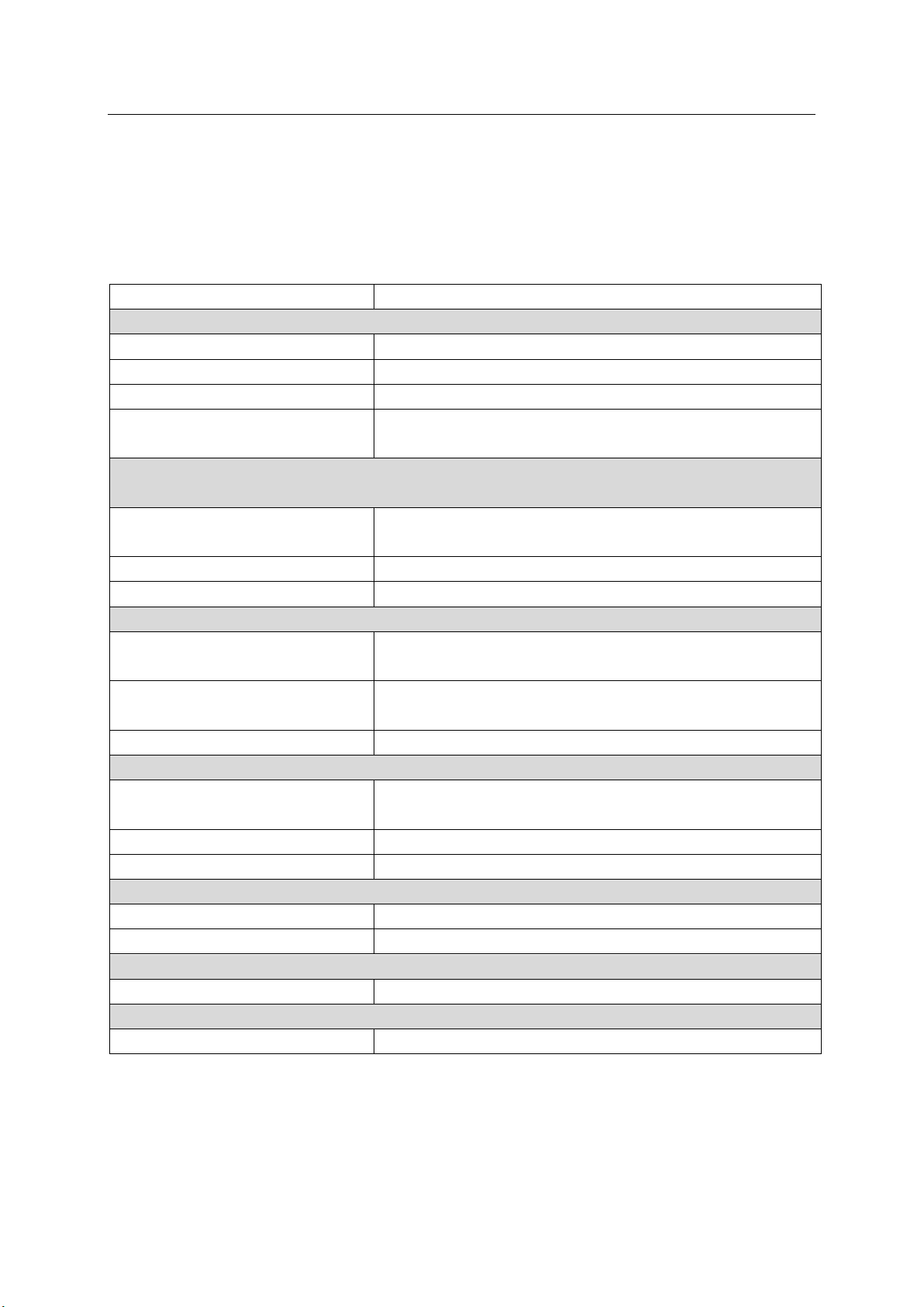
4.4 Electrical Trouble Shooting
Possible Reason
Suggested Solution
There is output current when pushing the torch trigger to feed gas, but the wire feeder does not work.
The control cable of the wire feeder is broken
Get it repaired or replaced
The wire feeder is clogged.
Unclog it.
The wire feeder fails.
Repair it.
The control PCB or wire-feeder power PCB inside
the machine fails
Replace it.
When the torch trigger is pushed, there is gas output and the wire feeder works, but there is no output
current, and the protection LED is off.
The earth cable is not well connected with the
work piece
Reconnect it.
The wire feeder cable is not well connected.
Reconnect it.
The wire feeder or welding torch fails
Repair the wire feeder or welding torch
No response when pushing the torch trigger and the protection LED is off
The welding torch is not well connected with the
wire feeder.
Reconnect it
The control cable of the wire feeder is not well
connected with the welding power supply
Reconnect it
The torch trigger fails.
Repair or replace the welding torch.
The fan does not work or it works abnormally
The mains power supply or the mains supply
cable is not connected
Reconnect the mains supply cable
Phase failure
Solve the phase failure problem.
The mains voltage is too low
Welding can be carried out after the mains voltage recovers
There is no no-load voltage
The mains voltage is too low.
Welding can be carried out after the mains voltage recovers.
Phase failure
Solve the phase failure problem.
The no-load voltage is “0”, and the overheating LED is on.
Overheating protection
It will recover automatically after the welding machine is cooled.
Other malfunction
Contact the service center of your distributor
In the event of equipment malfunction, contact an authorized service agent
The following operation requires sufficient professional knowledge on electric aspects and comprehensive
safety knowledge. Make sure the input cable of the machine is disconnected from the electricity supply and
wait for 5 minutes before removing the machine covers Before taking your unit for servicing, check the list
below.
TitanMig Pulse 2700/3500/5000 Operators Manual
Issue. A 0516 59
Page 64

5.0 Maintenance
The utilization level of the power source and its working environment should be taken into consideration
in planning the frequency of maintenance of the machine. Appropriate use and preventive maintenance
guarantee the trouble-free use of the equipment. This allows you to avoid interruptions in use and
increases the productivity of the machine.
5.1 Cables
Check the condition of welding and mains cables daily. Do not use damaged cables. Also make sure that all
extension cables used in the mains connection are in proper condition and compliant with regulations.
NOTE! The mains cables may be repaired and installed only by electrical contractors and installers
authorized to perform such operations.
5.2 Power source
Before cleaning the interior of the machine, you need to remove the case by unscrewing the mounting
screws at the top and sides of the machine.
NOTE! To prevent damage, wait approximately two minutes after disconnecting the mains cable before
removing the machine’s case. Perform the following cleaning and maintenance at least every six months:
1. Clean the interior of the machine and the fan grill’s net of any dust and stains – for
example, with a soft brush and vacuum cleaner.
•Do not use pressurized air. The stain may become compressed into the grooves of the coolers.
•Do not use a pressure-washing device.
2. Check the electrical connections of the machine. Clean any oxidized connections, and tighten the
loosened ones.
•Check for the right tension before you start repairing the connections.
NOTE! Remember that the machine may be repaired only by an electrical contractor or installer
authorized to perform such operations.
5.3 Regular maintenance
Authorized service agents perform regular maintenance by agreement. Tasks included in regular
maintenance:
Cleaning Equipment
Inspection and maintenance of the welding gun.
Checking of connectors, switches, and control knobs.
Checking electrical connections.
Checking the mains cable and plug
Replacement of damaged or worn parts.
Calibration testing, with adjustment of the functions and operational values of the machine, if
necessary
TitanMig Pulse 2700/3500/5000 Operators Manual
Issue. A 0516 60
Page 65
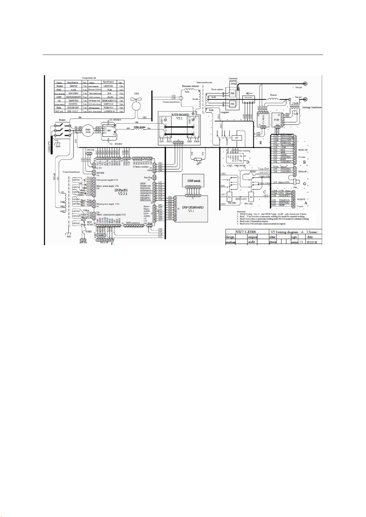
6.0 Electrical Diagram
TitanMig Pulse 2700/3500/5000 Operators Manual
Issue. A 0516 61
Page 66

7.0 Warranty Terms & Conditions
Weldtronic International P/L: ABN 99 149 754 263
Weldtronic International P/L (Weldtronic) warrants to the original retail purchaser that the
products supplied by us and purchased by you from an authorized We ldtronic distributor are free
of material and faulty workmanship defects except for those products listed under Warranty
Exclusions.
All warranty periods are from date of purchase from the retailer/distributor of the product.
Unless otherwise stated the warranty period includes parts and labour.
If a defect in material or workmanship becomes evident during the warranty period, Weldtronic
will, at its opinion, either:
Repair the Product (or pay for the costs of repair of the product); or
Replace the Product if repair is not possible.
In the unlikely event of such a defect, the customer should return the product to the original
place of purchase, with a proof of purchase, or contact Weldtronic on 03 9702 9366 to locate a
authorized service agent.
Any handling and transportation costs (and other expenses) incurred in claiming under this
warranty are not covered by this warranty and will not be borne by Weldtronic.
Weldtronic will return the replacement or repaired product, if original found to be faulty, freight
free to the customer.
The obligation of Weldtronic International P/L under this warranty is limited to the circumstances
set out above and is subject to:
The customer being able to provide proof of purchase of the product and the purchase
price paid for the product;
The relevant defect in materials or workmanship;
The product not having been altered, tampered with or otherwise dealt with by any
person in a manner other than as intended in respect of the relevant product; and
The product not having been used or applied in a manner that is contrary to customary
usage or application for the relevant product or contrary to any stated instructions or
specification of Weldtronic International.
Our products come with a guarantee that cannot be excluded under the Australian Consumer Law.
You are entitled to a replacement or refund for a major failure and for compensation for any
other reasonably foreseeable loss or damage. You are also entitled to have the goods repaired or
replaced if the goods fail to be of an acceptable quality and the failure does not amount to a
major failure. The benefits given by this warranty are in addition to the other rights and remedies
which may be available to the customer under any law in relation to goods and services to
which this relates.
These terms and conditions supersede and exclude all former and other representations and
arrangements relating to any warranties on these products
TitanMig Pulse 2700/3500/5000 Operators Manual
Issue. A 0516 62
Page 67

Warranty Periods
We offer the following Warranty Periods from date of purchase;
Equipment Power Sources
TitanTIG, TitanMIG, TitanARC Inverter Series (Power Source) 2 Years (Clause 2)
TronicTig, TronicMIG, TronicPlas Inverter Series (Power Source) 2 Years (Clause 2)
EuroMIG Transformer MIG Series (Power Source) 3 Years (Clause 1&2)
TronicCool Water Coolers 1 Year (Clause 2)
Electrode Ovens 1 Year (Clause 2)
Straight Line & Pipe Cutters (Power source only) 1 Year (Clause 2)
Positioners & Rotators (power source only) 1 Year (Clause 2)
Gas apparatus
TronicFlame Gas & Welding Kits 3 Months (Clause 2&4)
TronicFlame Regulators 1 Year
Automatic Welding Helmets
Clearwelding® CWH720S Series Automatic Helmet 1 Year (Clause 4)
Clearwelding® CWH800S / 815S / 820S Series Automatic Helmet 2 Years (Clause 4)
Welding Accessories
MIG , TIG & Plasma Torches 3 Months
Earth & Work Leads 3 Months
Gas Hose & Interconnecting Cables 3 Months
(Clause 1) 3 Year warranty on transformer, inductor, & Rectifier. 2 Year Warranty on PCB and all other
components.
(Clause 2) This only covers manufacture defaults on all accessories for the first three months after date of
purchase (e.g. MIG/TIG/Plasma Torches, Earth Leads, Gas hose, etc.).
(Clause 3) Gas Hose & Flashback arrestors are subject to and covered by the manufacturer’s individual
warranty.
(Clause 4) 1 & 2 Year warranty on ADF Lens. 3 Month warranty on Helmet shell, harness & fittings.
Warranty, Ret urns & Exc h ange s
(1)Subject to the conditions of warranty set out in the warranty period, Weldtronic International P/L
warrants that if any defect in any workmanship on any product has occurred then the conditions applicable
to the warranty period are;
(a)The warranty applies on the basis of the goods being used on the equivalent of single daily eight (8) hour
shift.
(2)The warranty shall not cover defect or damage which may be caused or partly caused by or arise through:
(a)Failure on the part of the buyer to properly maintain any goods.
(b)Failure on the part of the buyer to follow any instructions or guidelines provided by Weldtronic.
(c)Any use of any goods otherwise than for any application specified on a quote or order form.
(d)The continued use of any goods after any defect becomes apparent or would have become apparent to
a reasonably prudent operator or user.
(e)Fair wear and tear of goods or any part thereof including but not limited to items listed in warranty
exclusions.
(f)Misuse, neglect, accident, vandalism or damage in transit or natural disaster.
(3)The warranty shall cease and Weldtronic International P/L shall thereafter in no circumstances be liable under the
terms of the warranty if the workmanship is repaired, altered or overhauled without Weldtronic International
consent.
(4)In respect of all claims Weldtronic International P/L shall not be liable to compensate the buyer for any delay
in either replacing or remedying the workmanship or in properly assessing the buyers claim.
TitanMig Pulse 2700/3500/5000 Operators Manual
Issue. A 0516 63
Page 68

(5)For goods not manufactured by Weldtronic International P/L, the warranty shall be the current warranty
provided by the manufacturer of the goods. Weldtronic International shall not be bound by nor be responsible for
any term, condition, representation or warranty other than which is given by the manufacturer of the goods.
(6)We understand that sometimes you may need to return a product you have purchased from Weldtronic
International p/l authorized dealer, to assist you , we have set out below the Weldtronic International P/L
Returns Policy that you should know.
Our Returns Policy includes the rights you have under the Australian Consumer Law and other relevant laws.
Your rights under the Australian Consumer Law;
Our goods come with guarantees that cannot be excluded under the Australian Consumer Law. You are entitled to a
replacement or refund for a major failure and for compensation for any reasonably foreseeable loss or damage. You are
also entitled to have the goods repaired or replaced if the goods fail to be of acceptable quality and the failure does not
amount to a major failure.
You shall inspect the goods on delivery and shall within seven (7) days of delivery notify Weldtronic
International P/L of any alleged defect, shortage in quantity, damage or failure to comply with the
description or quote.
You shall also afford Weldtronic International P/L the opportunity to inspect the goods within a reasonable
time following delivery if you believe the goods are defective an any way.
If you fail to comply with these provisions the goods shall be presumed to be free from any defect or damage. For defective
goods, which Weldtronic International P/L has agreed in writing that you are entitled to reject, Weldtronic International P/L
liability is limited to either (at Weldtronic discretion) replacing the goods or repairing the goods except where you have
acquired goods as a consumer within the meaning of the Trade Practices Act 1974 or the Fair Trading Acts of the relevant
state or territories of Australian, and is therefore also entitled to, at the consumers discretion either a refund of the
purchase price of the goods, or repair of the goods, or replacement of the goods.
(7)Returns will only be accepted provided that;
(a)You have complied with the provisions outlined above, and…
(b)Where the goods are unable to be repaired, the goods are returned at your cost within thirty (30) days of
the delivery date, and…
(c)Weldtronic International P/L will not be liable for goods which have not been stored or used within the
proper manner, and…
(d)The goods are returned in the condition in which they were delivered and with all packaging material, brochures and
instruction material in as new condition as is reasonably possible in the circumstances. Failure to comply to this point
may mean that a re-stocking fee is charged to compensate Weldtronic for any lost materials and labour.
(8)Weldtronic International P/L accepts no responsibility for products lost, damaged or mislaid whilst in
transit.
(9)Weldtronic International P/L (at their sole discretion) accepts the return of goods for credit but this may
incur a handling fee of up to twenty percent (20%) of the value of the returned goods plus any freight costs.
(10)Where the failure does not amount to a major failure, Weldtronic International P/L is entitled to choose
between providing you with a repair, replacement or other suitable remedy.
(11)Your rights under the Australian Consumer Law are not limited by a defined time. However, the Australian
Consumer Law does recognize the relevant time period can vary from product to product, depending on factors such
as the nature if the product and price. Weldtronic International P/L adopts the same approach. As you can appreciate,
the type of remedy we can offer you may also vary depending on how long it takes you to return the product to use.
TitanMig Pulse 2700/3500/5000 Operators Manual
Issue. A 0516 64
Page 69

Making a Claim
(12)If you wish to make a claim under this warranty you should;
(a)Return the product to the point of purchase either in person or on a prepaid courier; or
(b)Contact us by telephone on 03 9702 9366 or mail to PO 2096 Rowville VIC 3178
(c)When returned, the product must be accompanied with the original invoice including the purchase price and
disclosing the purchase date.
(d)All costs of installation, cartage, freight, travelling expenses, hiring tools and insurance are paid by the Customer.
(e)To the extent permitted by law, our total liability for loss or damage of every kind related to the
product in any way whatsoever is limited to the amount paid to the retailer by you for the product or
value of the product.
Warranty Exclusions
(13)This warranty covers material and faulty workmanship defects only. This warranty does not cover
damage caused by
(a)Normal wear and tear due to usage
(b)Misuse or abusive use of the instructions supplied with the product
(c)Failure to clean or improper cleaning of the product
(d)Failure to maintain the equipment such as regular services etc.
(e)Incorrect voltage or non-authorized electrical connections
(f)Improper installation
(g)Use if non-authorized/non-standard parts
(h)Abnormal product performance caused by any ancillary equipment interference or other external factors.
(i)Failure or breakage caused by overload, dropping or abusive treatment or use by the customer
(j)Repair, modifications or other work carried out on the product other than by an authorized Weldtronic
service dealer.
(14)This warranty does not cover the following parts:
(a)MIG , TIG & Stick (MMA) Welding Torches & Consumables such as;
Gas nozzles, Gas diffusers, contact tip holder, contact tip, swan necks, trigger, handle, liners, wire guide, drive roller, neck
spring, connector block, insulator, gas nipple , cap, euro block, head assembly, gas block, trigger spring, cable support,
neck insulator, lock nut, arc leas, welding cable, electrode holders & earth clamps, tungsten Electrodes, Collect, Back Cap,
Collet body, Torch head, gaskets, gas lens & O-rings.
Plasma (b)Cutting Torches & Consumables such as;
Cutting tips, Air diffuser, Swirl ring, Electrode, retaining cap, nozzle spring, spaces, air & power cables,
O-rings, guides, torch bodies, air filter
(c)Straight Line & Pipe Cutting consumables such as; Hoses, fittings, track, cutting nozzles, torch
(15)This warranty does not cover for products purchased:
(a)From a non-authorized Weldtronic dealer (such as purchases from unauthorized retailers and purchases over the
internet from unauthorized local/international sites such as EBay)
(b)At an auction
(c)From a private seller
(d)Unless it is a manufacturing fault, this warranty does not apply for products sold to hire
companies.
These conditions may only be varied with the written approval of the directors of Weldtronic
International P/L.
REMEMBER TO RETAIN YOUR ORIGINAL INVOICE FOR PROOF OF PURCHASE.
TitanMig Pulse 2700/3500/5000 Operators Manual
Issue. A 0516 65
Page 70

TitanMig Pulse 2700/3500/5000 Operators Manual
Issue. A 0516 66
Page 71

TitanMig Pulse 2700/3500/5000 Operators Manual
Issue. A 0516 67
Page 72

Weldtronic International P/L
ABN 99 149 754 263
42-46 Micro Circuit, Dandenong Sth
Victoria 3175 Australia
P.O Box 2096 Rowville
Victoria 3178 Australia
Tel: 03 9702 9366
Fax. 03 9702 9766
Email. [email protected]
Web. www.weldtronic.com.au
 Loading...