

Page 1

QUICKFLIGHT /
QUICKFLIGHT XL
FREE FALL DEVICE
Operator Manual
Models: QF150-12A / QFXL150-20A
NOTE TO OWNERS, INSTALLERS, AND OPERATORS
Always Read Instructions Before Use
The Operator Manual contains information relating to the proper installation, operation,
and maintenance of the QuickFlight Free Fall Device and includes all product registration
and warranty information. This document must be supplied to the Owner/Operator after
installation. Ensure that this Operator Manual is readily available to responsible parties at
all times.
Head Rush Technologies QuickFlight Free Fall Device Manual
P/N 18310-06
Head Rush Technologies products are covered by a number of patents, including
U.S. Patents 8,490,75 1; 8,851, 235; 9,016,435 a nd D654,412 & corresponding patents/applications in the USA and in other
countries worldwide.
Page 2
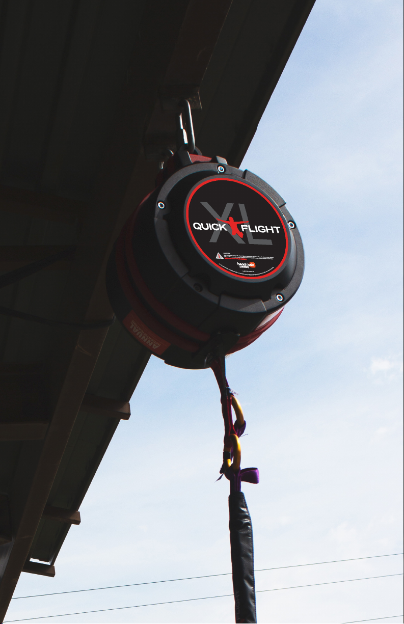
Page 3

TABLE OF CONTENTS
Important Safety Warnings
Health and Safety
Site Rescue Plan
1.0 SAFETY INFORMATION 7
Symbols Used in this Manual
2.0 WARRANTY CONDITIONS 8
2.1 Owner Responsibility
3.0 CERTIFICATION 10
3.1 Standards
10
4.0 DESCRIPTION 11
5.0 SPECIFICATIONS 12
5.1 All QuickFlight Models
5.2 Mounting Heights
12
13
6.0 QUICKFLIGHT PARTS 15
6.1 Labels
6.2 Icon Descriptions
16
17
7.0 UNPACKING 19
7.1 Precautions
7.2 Receipt of the QuickFlight Free Fall Device
7.3 Unpacking the QuickFlight Free Fall Device
7.4 Storage
19
19
19
20
8.0 INSTALLATION 21
8.1 Precautions
8.2 Standards
8.2.1 Anchor Points
8.2.2 Harness
8.2.3 Secondary Connectors
8.2.4 Selecting a Location
8.2.5 Outdoor Installations
8.2.6 Mounting Points
21
21
21
22
22
23
24
24
5
6
6
7
8
www.headrushtech.com | +1-720-565-6885
3
Page 4

8.2.7 Mounting Diagram
8.2.8 Location Diagram
25
26
9.0 OPERATION 27
9.1 Operator Training
9.2 User Instruction
9.3 Proper Harness Connections
9.4 Carabiner Operation
9.5 Proper Webbing Retraction
28
28
31
31
32
10.0 INSPECTION AND MAINTENANCE 33
10.1 Annual Recertification
10.2 Scheduled Maintenance
10.2.1 Safety Precautions
10.3 Daily Inspection
10.3.1 Upper Webbing Inspection
10.3.2 RipCord Webbing Inspection
10.4 Weekly Inspection
10.5 Bi-Annual Inspection
10.5.1 Inspection Procedure
10.6 Upper Webbing Replacement
10.7 Nozzle Replacement
10.8 Side Cover Replacement
10.9 RipCord Webbing Replacement
10.10 Long Term Storage
10.11 Replacement Part
10.12 Troubleshooting
10.13 Transportation
33
33
34
35
35
40
42
44
44
45
48
49
50
51
52
52
52
11.0 MANUFACTURER’S DETAILS 53
Address
Contact Details
53
53
4
headrushtech.com | +1-720-565-6885
Page 5

Important Safety Warnings
READ BEFORE INSTALLATION & OPERATION
RECREATIONAL DESCENT IS A DANGEROUS ACTIVITY.
THE QUICKFLIGHT FREE FALL DEVICE IS PRIMARILY USED AS A RECREATIONAL
FREE FALL DEVICE. IT CAN BE USED FOR CLIMBING PROTECTION. A MANDA
TORY FALL ATTUENTATION SURFACE IS REQUIRED UNDER THE PARTICIPANT/
CLIMBER AT ALL TIMES. ADDITIONAL CARE MUST BE TAKEN AT THE TOP OF
THE CLIMB AS THE RIPCORD WILL PREVENT 100% OF THE WEBBING FROM RE
TRACTING. ADDITIONAL FREEFALL WHILE CLIMBING IS POSSIBLE, SO CARE AND
TRAINING FOR PARTICIPANTS IS REQUIRED.
USE OF THE QUICKFLIGHT FREE FALL DEVICE FOR ANY PURPOSES OTHER THAN
THOSE INTENDED BY THE MANUFACTURER ARE NOT PERMITTED AND MAY
RESULT IN SERIOUS INJURY AND/OR DEATH.
PRIOR TO INSTALLATION AND OPERATION, ALL RESPONSIBLE PARTIES MUST
HAVE READ AND SHOWN TO HAVE UNDERSTOOD ALL REQUIREMENTS, IN
STRUCTIONS, LABELS, MARKINGS AND SAFETY INFORMATION PERTAINING TO
THE CORRECT INSTALLATION, OPERATION, INSPECTION, AND MAINTENANCE
OF THE QUICKFLIGHT FREE FALL DEVICE, ITS COMPONENT PARTS, AND ALL
ASSOCIATED HARDWARE AND SYSTEMS. FAILURE TO DO SO MAY RESULT IN
EQUIPMENT DAMAGE, SERIOUS INJURY, OR DEATH.
QuickFlight Free Fall Device Models QF150-12A, QFXL150-20A, and associated
equipment are designed and specified for use as rapid descent devices.
Owners and Operators of the QuickFlight Free Fall Device are responsible for
the safety and supervision of any person using the QuickFlight Free Fall Device
and are required to ensure that proper installation, operation, and maintenance
procedures are followed at all times. Proper installation requires careful design
and planning using QuickFlight and non-QuickFlight components. Owners,
Installers, and Operators are required by the Manufacturer to read, understand, and follow all instructions in this Operator Manual regarding the correct
installation and operation of the QuickFlight Free Fall Device prior to any use.
Owners and Operators are encouraged to seek the advice of their Installer or a
qualified engineering professional regarding the instructions in this Manual.
These instructions must be made readily available to the Owners, Installers,
and Operators of the QuickFlight Free Fall Device at all times. Prior to installation and use of the device, all Owners, Installers, and Operators must have read
and shown to have understood all instructions, labels, markings, and safety
information pertaining to the installation, operation, care, and maintenance of
the QuickFlight Free Fall Device system, its component parts, and all associated hardware.
headrushtech.com | +1-720-565-6885
5
Page 6

Health and Safety
Owners and Operators must abide by all Standards, International, Federal, State
and Provincial laws, and any specific health and safety regulations pertaining to
the installation and use of this product.
Site Rescue Plan
Owners and Operators must have devised an emergency rescue plan for any
Participant in distress at all sites operating QuickFlight Free Fall Devices. Operators must inform Users of the QuickFlight Free Fall Device of the procedure
for rescuing a Participant in distress prior to descent.
6
headrushtech.com | +1-720-565-6885
Page 7
1.0 SAFETY INFORMATION
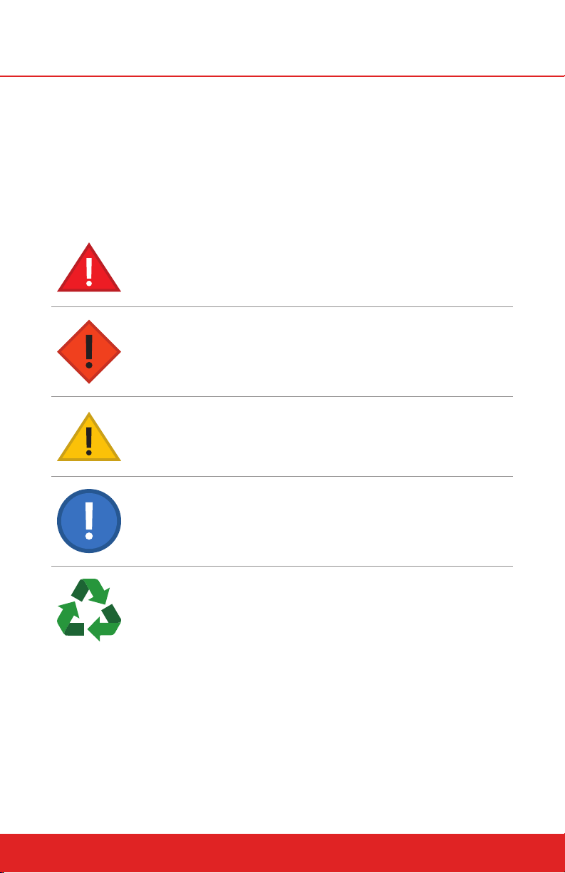
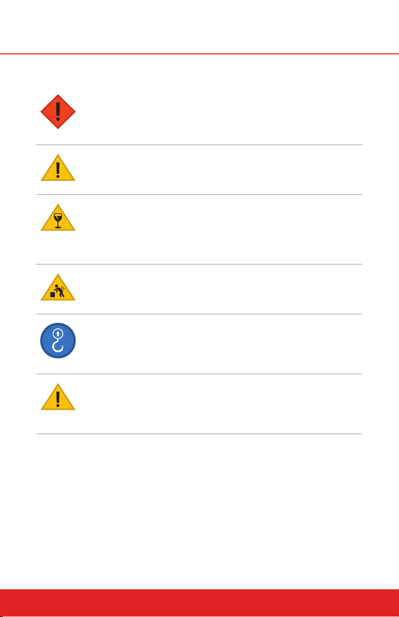
Symbols Used in this Manual
The following safety symbols are used throughout this manual to highlight
potential dangers. One or more precautions may be associated with practices
and procedures described within this manual. Failure to adhere to any precautions highlighted can result in death, serious injury, or equipment damage.
Ensure that you read and understand all safety procedures related to the working environment and the task you are performing.
DANGER
Indicates a hazardous situation exists that, if not avoided, will
result in serious injury or death.
WARNING
Indicates a potentially hazardous situation that, if not avoided,
could result in serious injury or death.
CAUTION
Indicates a potentially hazardous situation that, if not avoided,
may result in injury or equipment damage.
NOTE
Indicates an action that must be taken to ensure personal safety and prevent damage to property or equipment.
CARE FOR THE ENVIRONMENT
Take care to minimize impact on the environment when carrying out this procedure.
headrushtech.com | +1-720-565-6885
7
Page 8

2.0 WARRANTY CONDITIONS
This QuickFlight Free Fall Device is warrantied against factory defects in materials and workmanship (excluding “Replacement Parts” – see below) for a
period of two (2) years from date of purchase. This warranty applies only to the
original purchaser, and is contingent upon the Owner/Operator maintaining
and using the device in accordance with Manufacturer’s instructions, including
the requirement to continue to maintain annual re-certification as described in
the Operator’s Instruction Manual. This Warranty is in lieu of all other warranties, express or implied.
The sole remedy for breach of this warranty, or for any claim in negligence
or strict liability in tort, is the repair or replacement of any defective parts by
Head Rush Technologies. Upon notice in writing, Head Rush Technologies
will promptly repair or replace all defective items. Head Rush Technologies
reserves the right to have any defective equipment returned to its plant, transportation pre-paid, for inspection before making a repair or replacement.
This Warranty is null and void if parts other than genuine parts are used, or if
any modifications or services have been performed on the device by anyone
other than an authorized Head Rush Technologies servicing agent. This warranty does not cover any damages resulting from abuse to the device, damage
in transit, or any other damage beyond the control of Head Rush Technologies.
Head Rush Technologies makes no warranties in respect to trade accessories
or component parts which are not made by Head Rush Technologies. Head
Rush Technologies expressly excludes from this Warranty the replacement of
“Replacement Parts”.
No person, agent or Distributor is authorized to give any warranty, other than
the one herein expressed, on behalf of Head Rush Technologies, or to assume for it any liability pertaining to such products. Head Rush Technologies
expressly disclaims any implied guarantee of merchantability, or claim as to
whether the device is suited for a particular purpose. Purchaser agrees that
Head Rush Technologies shall not be held liable to Purchaser/Operator for
damages of any kind, including but not limited to, lost or projected profits,
equipment down time, or any losses considered to be caused by non-operation or servicing/re-certification down time of the equipment.
2.1 Owner Responsibility
The following items are considered to be the responsibility of the Owner/Operator and are therefore not reimbursable under the terms of the warranty.
Routine maintenance and inspection.
Normal replacement of service items.
Replacements required because of abuse, misuse or improper opera-
tional habits of the Operator.
8
headrushtech.com | +1-720-565-6885
Page 9

Wearing parts such as nozzle, webbing lines, RipCord webbings, cara-
biners, attachment rings, side covers, and lanyard keepers.
Normal deterioration due to use and exposure.
This warranty is subject to the following of the requirements of the Operator
Manual supplied, Manufacturer’s instructions, and the advice given by Head
Rush Technologies service technicians.
headrushtech.com | +1-720-565-6885
9
Page 10

3.0 CERTIFICATION
3.1 Standards
NOTE
If the QuickFlight Free Fall Device is resold outside of the country of destination, the reseller must provide instructions for use, service, maintenance
and repair in the language of the country of use.
The QuickFlight and the QuickFlight XL Free Fall Devices can be used as a
climbing/descent/free fall system device only in combination with other
components. It shall not be deemed suitable for use until it is ensured that the
entire system complies with the requirements of appropriate regional, state,
and federal directives/standards.
The QuickFlight and QuickFlight XL Free Fall Devices conform to Regulation
(EU) 2016/425 and comply with the following prevailing Safety regulations:
AS/NZS 1891: Industrial fall-arrest systems and devices – Part 3: Fall
arrest devices
CSA Z259.2.3-99: Descent Control Devices
EN 341: 2011 Class 1A: Personal protective equipment against falls from
a height – Descender devices
3rd party tested to 10x Class A
ANSI/ASSE Z359.4: Safety Requirements for Assisted-Rescue and
Self-Rescue Systems, Subsystems and Components.
EN 360:2002: Personal protective equipment against falls from a height
- Retractable type fall arresters
Section 4.5: Maximum force <6kN for 130kg capacity
EU Declaration of Conformity:
EU Declaration of Conformity can be downloaded at this website address:
https://headrushtech.com
Body controlling the manufacture of this PPE:
TÜV SÜD Product Service GmbH
Ridlerstraße 65
80339 München, Germany
Notified body performing the CE type exam:
TÜV SÜD Product Service GmbH
Ridlerstraße 65
80339 München, Germany
10
headrushtech.com | +1-720-565-6885
Page 11

4.0 DESCRIPTION
THE FIGURES PRESENTED IN THIS MANUAL ARE NOT TO SCALE AND MAY NOT
SHOW ALL REQUIRED COMPONENTS OR STRUCTURES, INCLUDING, BUT NOT
LIMITED TO: MOUNTING POINTS, CONNECTORS, SAFETY EQUIPMENT, ETC.
The QuickFlight Free Fall Device is a descent device designed specifically for
use as a component within a free fall system or climbing system. The design
of the QuickFlight Free Fall Device permits simple installation and removal and
incorporates an advanced self-regulating brake system and automatic webbing
line retraction. The patented braking mechanism oers Participants an initial
free fall followed by a consistent descent with a minimal variation in descent
rate of both children and adults.
Two models are available:
QF150-12A QuickFlight Free Fall Device
QFXL150-20A QuickFlight XL Free Fall Device
The QuickFlight Free Fall Device oers a standard free fall experience and may
be mounted at a low height range. The QuickFlight XL Free Fall Device provides an extended free fall experience but must be mounted at a higher height
range.
All QuickFlight Free Fall Devices use a unique dual webbing line configuration
for added redundancy and lower cost of ownership. This webbing configuration uses two Upper Webbing lines that extend into and out of the Device and
connect to a mandatory RipCord Lower Webbing. The RipCord also includes
an Overload Protection Assembly (OPA) that provides additional safety in the
event that the device ever stops functioning on descent.
Upper webbings are available in three lengths: Low Mount, Standard, and XL. The
device should never be used with un-matched Upper Webbing lengths. Two RipCord variants are available: the 1m RipCord for a standard free fall experience
or the 2m RipCord for an extended free fall experience. As with the Device and
Upper Webbing selections, the RipCord length influences the required installation height. Refer to the full specifications based on your Device model, Upper
Webbing length, and RipCord length for proper installation details.
To protect the longevity of the QuickFlight Free Fall Device, installation, care
and use of the QuickFlight Free Fall Device must be carried out in accordance
with the instructions in this manual. It is the responsibility of the Installer/Operator to ensure that an allowable webbing configuration is used in the device, and to
always mount the QuickFlight Free Fall Device within the stated mounting height
limits for the Upper Webbing, Lower Webbing, and Device combination used.
The theoretical lifespan of the QuickFlight and QuickFlight XL device is unlimited
with proper care and performing the required annual service maintenance. For
planning purposes, we recommend a planned lifespan of 15 years.
headrushtech.com | +1-720-565-6885
11
Page 12

5.0 SPECIFICATIONS
Every QuickFlight Free Fall Device comes with two Upper Webbings and a
RipCord assembly pre-installed. The Owner should keep the original packaging
to use for storage and shipping of the device.
5.1 ALL QUICKFLIGHT MODELS
CERTIFICATION
DIMENSIONS 0.43 x 0.33 x 0.25 m (17 x 13 x 10 in)
DISTANCE
NET WEIGHT 25 kg (55 lbs)
MATERIALS CASING Aluminum Alloy
USER WEIGHT
IN ACCORDANCE WITH EN 341:2011-1A AND
EN 360:2002
NOZZLE TO PRIMARY
MOUNTING POINT
INTERNAL
PARTS
NOZZLE Modified Acetal plastic
NOZZLE INSERT 304 Stainless Steel
LINE
CONDI-
TION
---------
----
MINIMUM MAXIMUM
20 kg (44 lbs) 130kg (285 lbs)
0.405 m (15.94 in)
Zinc plated steel
Stainless steel
Polyamide/Ultra High Molecular Weight Polyethylene
OPERATING
TEMPERATURE
STORAGE
TEMPERATURE
LANDING SPEED
12
ANY -4° C (25° F) 60° C (140° F)
DRY -10° C (14° F) 60° C (140° F)
---------
----
---------
----
-20° C (-4° F) 60° C (140° F)
-------------
headrushtech.com | +1-720-565-6885
1.5 - 6.0 m/s
(4.9 - 19.7 ft/s)
Page 13

METRIC UNITS ARE THE CONTROLLING UNITS OF MEASURE IN THIS MANUAL.
IMPERIAL UNITS ARE PROVIDED AS A COURTESY AND HAVE BEEN ROUNDED. IF
THE OWNER/OPERATOR/INSTALLER MUST MAKE ANY UNIT CONVERSIONS, THE
METRIC UNITS SHOULD BE REFERENCED.
5.2 MOUNTING HEIGHTS
Nozzle to Platform
MODEL MINIMUM MAXIMUM
ALL MODELS 1.75 m (5.7 ft) 2.50 m (8.2 ft)
QuickFlight Standard Free Fall Device, QF150-12A
MODEL MINIMUM MAXIMUM
LOW MOUNT UPPER WEBBINGS &
1 M RIPCORD
12 M UPPER WEBBINGS &
1 M RIPCORD
12 M UPPER WEBBINGS &
2 M RIPCORD
QuickFlight XL Free Fall Device, QFXL150-20A
6.0 m (19.7 ft) 8.3 m (27.2 ft)
8.0 m (26.3 ft) 14.3 m (46.9 ft)
9.0 m (29.6 ft) 15.3 m (50.1 ft)
MODEL MINIMUM MAXIMUM
20 M UPPER WEBBINGS &
1 M RIPCORD
20 M UPPER WEBBINGS &
2 M RIPCORD
* Mounting heights are from nozzle to landing zone and may vary with the
addition of authorized QuickFlight accessories.
headrushtech.com | +1-720-565-6885
12.0 m (39.4 ft) 21.8 m (71.5 ft)
13.0 m (42.7 ft) 23.0 m (75.4 ft)
13
Page 14
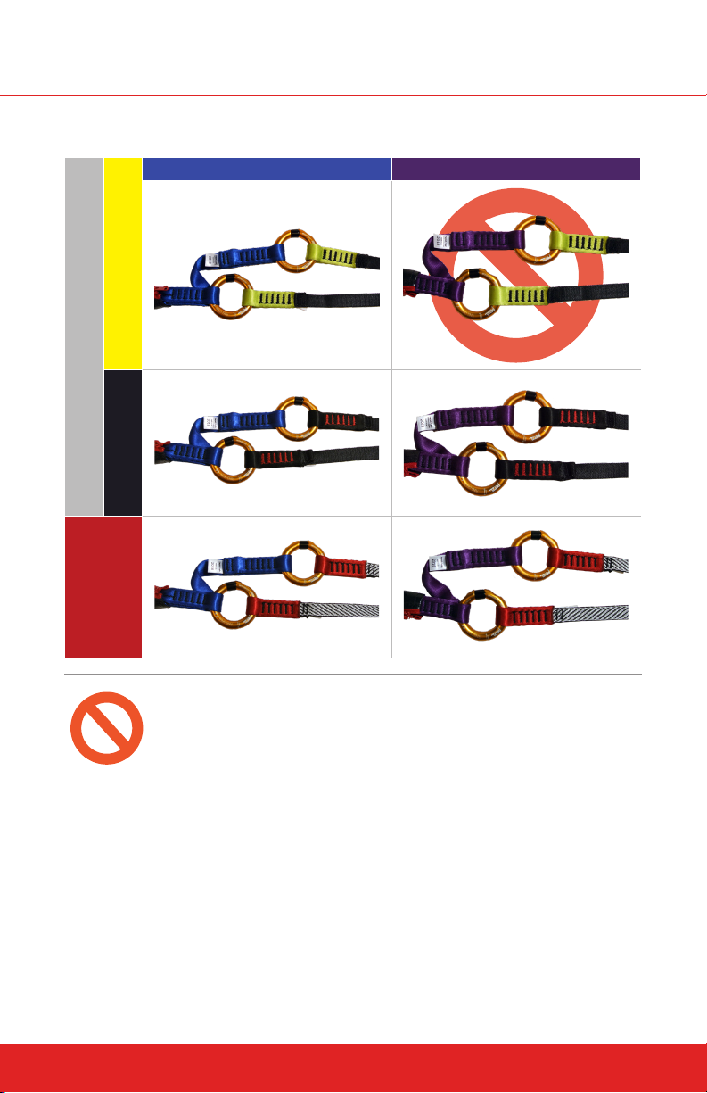
QuickFlight Webbing Configurations
1M RIPCORD 2M RIPCORD
LOW MOUNT
QUICKFLIGHT
STANDARD
QUICKFLIGT XL
14
THE QUICKFLIGHT FREE FALL DEVICE WITH LOW MOUNT UPPER WEBBINGS MAY
NOT BE USED WITH THE 2M RIPCORD. ENSURE THAT AN ALLOWABLE COMBI
NATION OF DEVICE, UPPER WEBBINGS, RIPCORD WEBBINGS, AND MOUNTING
HEIGHT IS IN PLACE BEFORE LIVE OPERATION OF THE QUICKFLIGHT FREE FALL
DEVICE.
headrushtech.com | +1-720-565-6885
Page 15
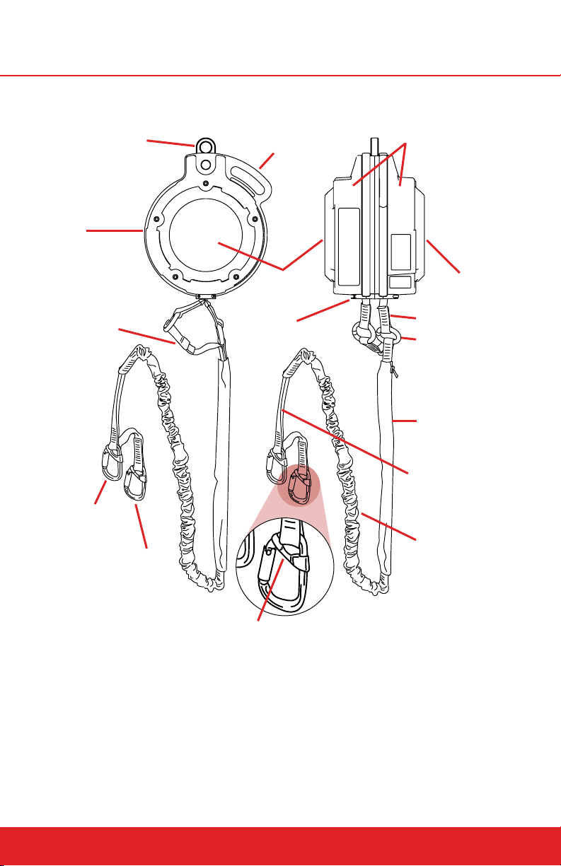
6.0 QUICKFLIGHT PARTS
Primary Mounting
Point (Black)
QuickFlight
Device
RipCord Webbing
Primary
Attachment
Carabiner
Secondary
Attachment
Carabiner
Handle / Secondary
Mounting Point (Red)
Side Cover
(Front)
Nozzle
Casing
Side Cover
(Back)
Upper Webbing
Webbing
Connection Rings
OPA Jacket
Hand Grip
RipCord
Bungee
Lanyard Keeper
headrushtech.com | +1-720-565-6885
15
Page 16
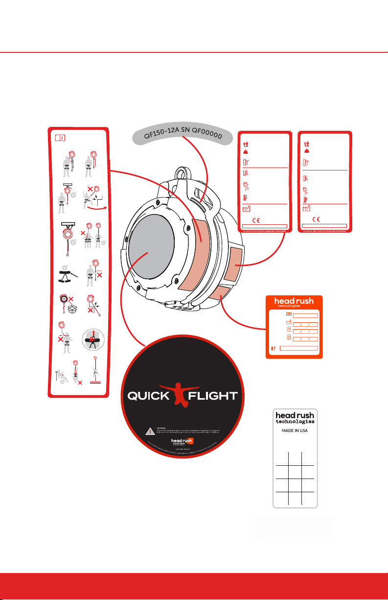
6.1 Labels
10015-03
11762-02
18308-03
18307-03
1.
2.
4.
6.
8.
10.
12.
13. 14.
11.
9.
3.
5.
7.
EN 12277,
UIAA 105,
EN 361
18309-03
ALWAYS READ AND FOLLOW
THE WARNINGS AND
INSTRUCTIONS FOR USE
EN 362/EN 12275
PADDING
YYYY
Jan.
Apr.
Jul.
Oct.
Feb.
May
Aug.
Nov.
Mar.
Jun.
Sept.
Dec.
INFORMATION
LABEL
SERIAL LABEL
QF15012A SN QF00000
QFXL15020A SN QFXL00000
SPECIFICATION LABEL
VARIES BY MODEL
MODEL: QFXL150-20A
RATED BODY WEIGHT:
20 to 130kg (44 to 285lbs)
DEVICE WEIGHT:
25 kg (55 lbs
MOUNTING HEIGHT*:
1M Ripcord blue webbing end: Max.
21.8 m (71.5 ft)
2M Ripcord purple webbing end: Max.
23.0 m (75.4 ft)
1M Ripcord blue webbing end: Min.
12.0 m (39.4 ft)
2M Ripcord purple webbing end: Min.
13.0 m (42.7 ft)
* Mounting heights are measured from nozzle to ground
LANDING SPEED:
1.5 - 6.0 m/s (4.9 - 19.7 ft/s)
TEMPERATURE RANGE:
Operating (Any): -4°C to 60°C (25°F
to 140°F)
Operating (Dry): -10°C to 60°C (14°F
to 140°F)
HEAD RUSH TECHNOLOGIES
1835 38th Street
Boulder, Colorado 80301, USA
www.headrushtech.com
0123
IN ACCORDANCE WITH EN341:20111A AND EN 360:2002
MANUFACTURE DATE:
RECERTIFICATION DATE:
NEXT RECERT REQUIRED:
SERIAL NUMBER:
BY:
MODEL: QF150-12A
RATED BODY WEIGHT:
20 to 130 kg (44 to 285 lbs)
DEVICE WEIGHT:
25 kg (55 lbs
MOUNTING HEIGHT*:
Low Mount yellow webbing end: Max.
8.3 m (27.2ft)
1M Ripcord blue webbing end: Max.
14.3 m (46.9 ft)
2M Ripcord purple webbing end: Max.
15.3 m (50.1 ft)
Low Mount yellow webbing end: Min.
6.0 m (19.7 ft)
1M Ripcord blue webbing end: Min.
8.0 m (26.3 ft)
2M Ripcord purple webbing end: Min.
9.0 m (29.6 ft)
* Mounting heights are measured from nozzle to ground
LANDING SPEED:
1.5 - 6.0 m/s (4.9 - 19.7 ft/s)
TEMPERATURE RANGE:
Operating: -4°C to 60°C (25°F to 140°F)
Operating (Dry): -10°C to 60°C (14°F to
140°F)
HEAD RUSH TECHNOLOGIES
1835 38th Street
Boulder, Colorado 80301, USA
www.headrushtech.com
IN ACCORDANCE WITH EN341:2011-1A AND EN 360:2002
10024-02
0123
CERTIFICATION
LABEL
16
COVER LABEL BOTH
SIDES, VARIES BY MODEL
WEBBING DATE OF
MANUFACTURE LABEL
(Attached to Webbing)
headrushtech.com | +1-720-565-6885
Page 17
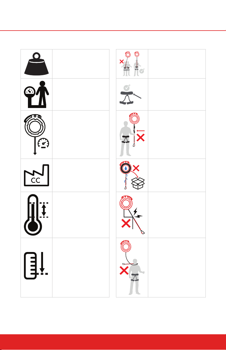
6.2 Icon Descriptions
,
,
EN 361
Device Weight Only one user at a time
Body Weight
Landing Speed
Country of Manufacture
Temperature Range
Minimum Height
Harness standards
EN 12277
UIAA 105
Do not alter the line. Do
not clamp, knot or tie on
additional line
Do not store the line
inside the device wet
Never install the device
where the line passes
over sharp edges, high
friction areas
Never permit line to wrap
around or become entangled with neck, arms,
or legs
headrushtech.com | +1-720-565-6885
17
Page 18
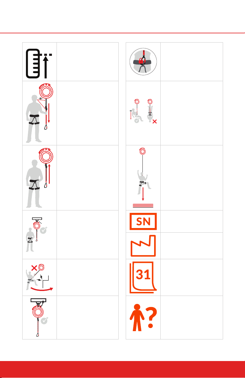
Maximum Height
PADDING
Inspect the Webbing
Connect the carabiner
to the designated belay
loop of your harness,
making sure the gate is
locked
Check descent path is
clear, Always land with
slightly bent knees to
absorb landing
Both lines must be fully
retracted before use.
EN 362/EN 12275
Minimum connector
strength for installation
Avoid swing falls into
objects
Primary connector
taught, secondary backup connector loose
Fall attenuation surface
required
Serial number
Manufacture Date
Date
Technician
18
headrushtech.com | +1-720-565-6885
Page 19

7.0 UNPACKING
7.1 Precautions
LEAVE THIS USER MANUAL ATTACHED TO THE QUICKFLIGHT
UNTIL INSTALLATION IS COMPLETE
The Operator Manual contains information relating to the safe use of the
QuickFlight Free Fall Device and includes all product registration and warranty information. The Operator Manual document may only be removed
by the end user. Ensure this manual is readily available to Free Fall Device
users at all times.
DO NOT DISPOSE OF PACKAGING
The cardboard box and internal packaging are required for the return of
the Free Fall Device for the annual Certification inspection. Please keep
packaging in a safe place until required.
7.2 Receipt of the QuickFlight Free Fall Device
The QuickFlight Free Fall Device is packaged in a recycled cardboard box and
contains:
1 x QuickFlight Free Fall Device with Upper Webbings Installed (model
and Upper Webbings will vary depending on the specifics of your order)
1 x RipCord Assembly (length will vary depending on the specifics of
your order)
2 x Webbing Connection Rings
2 x Carabiners
2 x Lanyard Keepers (Installed on Carabiners)
1 x Operator Manual
The QuickFlight Free Fall Device is shipped with the webbing lines and carabiners attached and does not require any further assembly.
7.3 Unpacking the QuickFlight Free Fall Device
To unpack the QuickFlight Free Fall Device:
1. Upon receipt of QuickFlight Free Fall Device, inspect for signs of shipping
damage or contamination. If QuickFlight Free Fall Device shows any signs
of damage or mishandling, contact your Head Rush Technologies distributor.
2. Check that all labels shown in this manual are properly axed to the
QuickFlight Free Fall Device and are legible.
headrushtech.com | +1-720-565-6885
19
Page 20

3. Check the Certification Label for the ‘Next Recertification Required’ date.
If the date shown has passed or the label is missing or illegible the QuickFlight Free Fall Device must not be put into service.
4. Register your QuickFlight Free Fall Device online at www.headrushtech.
com/registration
5. Read the Operator Manual and familiarize yourself with all aspects of
installation, operation, care and maintenance.
THE QUICKFLIGHT DEVICE IS HEAVY. USE CARE WHEN LIFTING! DROPPING
OR HARD IMPACTS TO THE QUICKFLIGHT FREE FALL DEVICE CAN RESULT IN
SERIOUS DAMAGE TO MOUNTING POINTS AND INTERNAL PARTS AND MAY
COMPROMISE SAFETY OF OPERATION. IF THE QUICKFLIGHT FREE FALL DEVICE
IS SUBJECTED TO A HARD IMPACT, REMOVE IT FROM DUTY AND RETURN TO AN
AUTHORIZED SERVICE CENTER FOR INSPECTION.
7.4 Storage
If the Free Fall Device is to be left unused for longer than two weeks, ensure
the unit is clean and dry and line is fully retracted into the unit.
When returning the Free Fall Device to duty after an extended period of inactivity, always carry out a full inspection and operational check.
DO NOT STORE IN WET CONDITION
After exposure to water or damp conditions thoroughly clean and dry the
Free Fall Device. Ensure Free Fall Device is not left with wet webbing line
retracted inside the casing. If the webbing is wet and the device is to be
stored, remove the nozzle and pull all the webbing out until the shackle is
exposed. Insert a pin through the line to prevent retraction, and allow the
webbing to dry naturally away from open fire or heat source.
Always store in a clean and dry environment.
20
headrushtech.com | +1-720-565-6885
Page 21
8.0 INSTALLATION
8.1 Precautions
ALWAYS USE DESIGNATED MOUNTING POINTS
Never install the Free Fall Device using any part of the device apart from the
designated mounting points. Incorrect mounting can result in serious injury or
death.
ALWAYS USE THE CORRECT MOUNTING HEIGHT
Failure to install the device at the correct mounting height could result in
damage to the device or loss in device performance.
HARD IMPACTS MAY RESULT IN STRUCTURAL DAMAGE
Dropping of, or hard impacts to, the Free Fall Device can result in serious
damage to mounting points and internal parts and may compromise safety
of operation. If the Free Fall Device is subject to a hard impact, remove it
from duty and return to a service agent for inspection.
HEAVY ITEM 25 KG 55 LBS
Take care when lifting the Free Fall Device. Take care not to drop the device as this may result in serious injury or equipment damage.
ALWAYS MOUNT VERTICALLY
Always mount the Free Fall Device vertically with the nozzle pointing
downwards and the line exiting the bottom of the device. Failure to do so
will result in incorrect operation and compromise User safety.
HARMFUL CONTACT
Do not allow solvents, acids, sharp edges etc. to get into contact with the
device, especially the webbing. If in contact, the Free Fall Device must be
inspected.
8.2 Standards
Prior to installation, all Operators must be familiar with the requirements of all
relevant Standards for anchor points, hardware and equipment used with the
Free Fall Device.
8.2.1 ANCHOR POINTS
At least two anchor points must be used to mount the QuickFlight Free Fall
Device. Do not attach Primary and Secondary Mounting Points to the same
anchor point. All anchor points and connectors used with a QuickFlight Free
Fall Device must conform to any federal or state requirements for such devices.
headrushtech.com | +1-720-565-6885
21
Page 22

Head Rush Technologies requires anchor points to have a minimum load capacity of 12 kN (2640 lbs) in expected directions of application. Other national
and international standards for anchor points may apply and require higher
load capacity. Consult with the authority having jurisdiction for your required
load capacity.
The location and anchor points for the QuickFlight Free Fall Device should
comply with the following:
Anchor points are not to be used by additional devices or as attach-
ments for hardware not associated with the Free Fall Device installation.
Anchor points should be of a suitable size to correctly install any mount-
ing hardware.
8.2.2 HARNESS
All harnesses used in conjunction with the QuickFlight Free Fall Device must
comply with one or more of the following standards or an equivalent standard
for your jurisdiction:
EN 361 - Personal protective equipment for prevention of falls from a
height – Full body harness.
EN 813 - Personal protective equipment for prevention of falls from a
height – Sit harness.
EN 12277 - Type A. Full Body Harness.
EN 12277 - Type B. Small Full Body Harness.
EN 12277 - Type C Sit Harness.
Harnesses must be of the correct size and fitment and be in serviceable condition.
8.2.3 SECONDARY CONNECTORS
All secondary connectors and hardware used in the installation of the QuickFlight must conform to the requirements of:
EN 362 - Types of connectors for personal protection.
EN 12275 - Types of connectors for mountaineering.
All connectors, hooks, D-rings and shackles used to mount the QuickFlight
must be of compatible size, shape and strength for the mounting point to
which they are attached.
IT IS THE OWNER/INSTALLER’S RESPONSIBILITY TO ENSURE COMPAT
IBILITY OF CONNECTORS IN DEVELOPING THE HARNESS/CONNEC
TION SAFETY SYSTEM. INCOMPATIBLE CONNECTIONS CAN RESULT IN
SERIOUS INJURY OR DEATH DUE TO UNINTENTIONAL DISCONNEC
TION DURING FREE FALL/DESCENT.
22
headrushtech.com | +1-720-565-6885
Page 23

Two EN 362 certified triple locking carabiners are installed on the primary and
secondary attachment points of the RipCord assembly for Participant connection. Two plastic Lanyard Keepers prevent the carabiners from rotating within
their attachment points. Two EN 362 certified attachment rings are installed
to connect the RipCord to the two Upper Webbings. The carabiners, lanyard
keepers, and webbing connection rings must be checked and be in serviceable condition according to the Manufacturer’s instructions before any use.
Ensure the carabiners are only loaded along the vertical direction (i.e. not cross
loaded).
The carabiners can be replaced with other EN 362 certified connectors at the
Owner/Installer/Operator’s discretion with the following requirements:
If a continuous or smart belay system (or any other system) lengthens
the distance between the Participant and the attachment points of the
RipCord, the minimum Nozzle to Platform distance must be increased
by the amount the connection is lengthened. The maximum Nozzle to
Platform distance may be increased by the same amount.
The Participant must remain connected to both the Primary and Sec-
ondary attachment points of the RipCord.
Any connector utilized must be suitably rated and meet the require-
ments of any applicable international, federal, state or provincial stan-
dards for its application.
When connections are made using carabiners, only triple locking
carabiners with a lanyard retaining feature are to be used. Head Rush
Technologies recommends the use of the Petzl Am’D carabiner with
Captiv lanyard keeper.
Connections to the QuickFlight and QuickFlight XL webbing assembly
have the potential for additional wear and must be included in daily
webbing inspections.
8.2.4 SELECTING A LOCATION
A PROTECTIVE FALL ATTENUATION SURFACE MUST BE USED AND CENTERED
BELOW THE LANDING POINT OF THE DEVICE, EXTENDING AS REQUIRED TO AD
EQUATELY PROTECT PARTICIPANTS FROM INJURIES. IT IS RECOMMENDED THE
SURFACE MEET ASTM F1292 SPECIFICATION OR EN 1177 DEPENDING ON THE
AUTHORITY HAVING JURISDICTION FOR IMPACT ATTENUATION OF SURFACING
MATERIALS FOR A CRITICAL FALL HEIGHT OF 3M 9.8FT. THE SURFACE MUST
BE AT LEAST 2.5M X 2.5M IN SIZE. A LARGER SURFACE MAY BE REQUIRED IF THE
DEVICE IS OPERATED IN WINDY CONDITIONS.
headrushtech.com | +1-720-565-6885
23
Page 24

When selecting a location to install the QuickFlight Free Fall Device, check:
Install the device where it can be safely reached for inspections and
servicing.
The QuickFlight Free Fall Device will hang vertically over the line of de-
scent with the nozzle pointing down. Ensure that the line of descent has
full clearance from obstacles and pedestrians within its fully extended
range, including areas to which the Participant may swing.
The webbing must not come in contact with the structure.
Ensure that descending on the device cannot cause the Participant to
experience dangerous pendulum swings into adjacent obstacles, even in
windy conditions.
Orient the device so that when participants jump, the FACE of the web-
bing is loaded, not the EDGE. If loading the EDGE, there will be acceler-
ated webbing wear.
8.2.5 OUTDOOR INSTALLATIONS
The QuickFlight Free Fall Device may be installed outdoors.
It is recommended that in wet or high-variable temperature environments, the
Free Fall Device is protected from the direct ingress of water or foreign objects.
NOTE
Prolonged exposure to the elements will increase the risk of internal
corrosion and degradation of the webbing line, resulting in increased
operation and servicing costs. Increased inspections are required in these
types of environments.
8.2.6 MOUNTING POINTS
With a suitable location for the QuickFlight Free Fall Device selected the device
must be mounted only using the methods and hardware described in this
manual. When mounting the QuickFlight Free Fall Device, be aware of the
following precautions:
DEVICE MOUNTING POINTS
USE ONLY THE DESIGNATED MOUNTING POINTS
Use only the correct mounting points. Use of incorrect points can result in
equipment damage.
Ensure all mounting hardware is secure but free to pivot in mounting
point.
24
headrushtech.com | +1-720-565-6885
Page 25
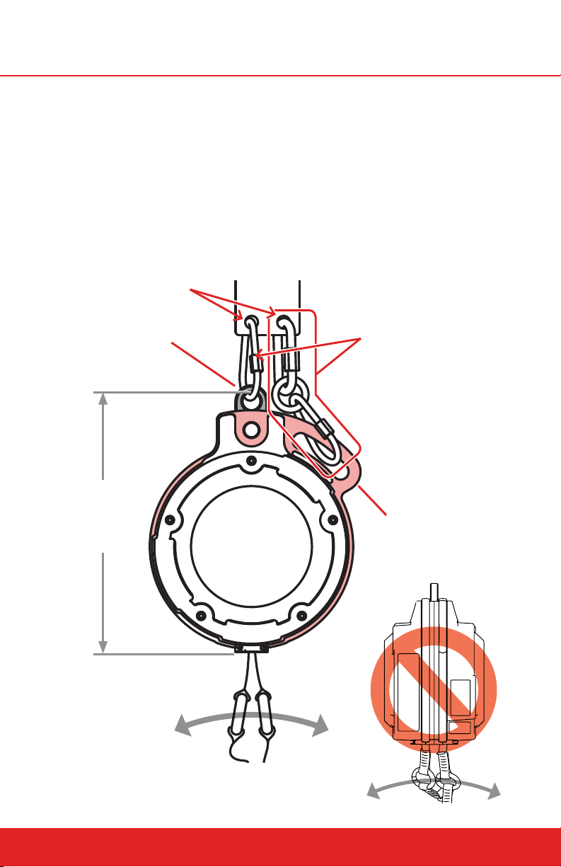
The QuickFlight Free Fall Device provides color-coded mounting points to ensure that it hangs centrally and vertically with the webbing line nozzle pointing
down. The black Primary Mounting Point should be used to hold the weight of
the device and all associated forces. The red Secondary Mounting Point should
be connected for redundancy using hardware that can withstand all associated
forces, but with no tension during normal operation. For optimal webbing life,
it is important to mount the device in a way that loads the Primary Mounting
Point without actively loading the Secondary Mounting Point.
8.2.7 MOUNTING DIAGRAM
ANCHOR POINTS
PRIMARY MOUNTING POINT
(Tight)
Use only approved
connectors
DISTANCE FROM
MOUNTING POINT
TO NOZZLE:
405MM
JUMP DIRECTION
MOUNTING
CONNECTORS
SECONDARY
MOUNTING POINT
(Loose)
Use only approved
connectors
headrushtech.com | +1-720-565-6885
JUMP
DIRECTION
25
Page 26
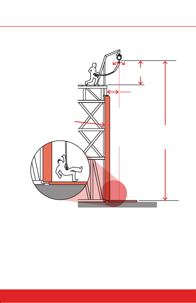
8.2.8 LOCATION DIAGRAM
Jump Direction
NOZZLE TO PLATFORM
1.75m - 2.5m
MINIMUM
1m
Any areas that may come in
contact with the participant
must be padded or protected.
PADDING
Adequate protection must be
in place for participants that
fall upon landing.
CENTER PLUMB LINE
NOZZLE TO GROUND
Mounting height range
varies. See limits for
device and webbing
configuration.
26
headrushtech.com | +1-720-565-6885
Page 27
9.0 OPERATION
Owners and purchasers of the QuickFlight Free Fall Device are responsible for
the safety and supervision of any person using this equipment and are required
by the manufacturer to read, understand and follow all instructions in this Operator Manual regarding the correct installation and operation of the Free Fall
Device prior to any use.
UNSAFE OPERATION
Remove Free Fall Device from service immediately if there is any concern
over its correct operation or user safety.
Do not return Free Fall Device to service until it has been inspected and
completed a recertification inspection and tested by an approved Head
Rush Technologies Service Agent.
EMERGENCY RESCUE PLAN
Owners and operators must have devised an emergency rescue plan for
any user in distress at all sites operating QuickFlight and QuickFlight XL
Free Fall Devices for climbing. Operators must inform Users of the Free
Fall Device of the procedure for rescuing a climber in distress prior to
climbing.
STOP USE IMMEDIATELY IF ANY OF THE FOLLOWING OCCUR:
Excessively fast webbing wear is noticed. Check unit mounting and
replace webbing. Place the device back in service and check that fast
webbing wear is resolved.
The landing speed increases from its normal level. Wait for the device
to cool down. Place the device back in service if landing speed has
returned to its normal level.
The device stops retracting webbing. Send the unit in for service.
EXTERNAL ITEMS PREVENTING RETRACTION
Any device that fails to retract or keep pace with the climber must be
removed immediately from service and diagnosed by the operator. If items
external to the device (see below for examples) are responsible for retraction problems, these must be corrected before placing the QuickFlight and
QuickFlight XL devices back into service. If items external to the device
have been removed, and retraction problems persist, immediately send the
device to your nearest authorized Head Rush Technologies service center.
Examples of external items that could prevent or aect retraction of a
QuickFlight and QuickFlight XL devices:
Foreign bodies becoming lodged in the nozzle.
Route marking tape interfering with the webbing and/or becoming
lodged in the nozzle.
Protruding handholds, climbing wall features or climbing equipment
interfering with lanyard retraction.
headrushtech.com | +1-720-565-6885
27
Page 28

9.1 Operator Training
All personnel involved in the operation of the Free Fall Device must be trained
and deemed competent in the following aspects of QuickFlight Free Fall Device
operation;
Transportation and storage.
Installation, use of attachment points and attachment methods and
hardware.
Inspection, cleaning, and scheduled servicing of the Free Fall Device, its component parts and associated attachment hardware.
9.2 User Instruction
NEVER USE WITHOUT BEING CORRECTLY ATTACHED
Ensure the carabiner is attached to the belay loop of the harness or other
approved anchor point and the latch is fully closed and the gate engaged
before starting to climb. A gate check must be performed after every
connection.
Failure to do so can result in serious injury or death.
WARNING
Climbing is considered a strenuous activity. If you have any physical or
medical conditions that may aect your climbing ability consult a medical
professional prior to participation.
POTENTIAL FOR PARTICIPANT ENTANGLEMENT
Potential for participant entanglement exists during descent. Ensure all
loose items that may become tangled are tightened or removed before
using the QuickFlight. A risk assessment should be completed at the installation site to determine the necessary PPE for users.
Prior to clipping in, all Participants must be instructed in the proper and correct
use of the QuickFlight Free Fall Device. Operators are to ensure all Participants
are familiar with the site rescue plan in the event the Participant becomes
distressed.
Prior to descent, the Participant and Operator must be aware of, completely
understand, and obey the following precautions:
Check Free Fall Device operation by pulling out a short section and
allowing it to retract.
If the Free Fall Device stops retracting for any reason while attached,
STOP CLIMBING. If there is no slack in the line, jump onto the
webbing and the Free Fall Device will descend. Notify the operator
immediately.
28
headrushtech.com | +1-720-565-6885
Page 29

If the Free Fall Device line fails to retract, do not clip into the Free Fall
Device and request assistance.
Ensure that the daily device inspection has been performed and that the
webbing line, carabiners, and device have not been damaged.
Use a helmet if determined necessary by a qualified person.
Do not allow Participants to descend with sharp objects (i.e. keys) in
pockets.
Ensure that Operators are anchored to the platform at all times. Partic-
ipants must be anchored to the platform AND attached to the Quick-
Flight UNTIL THEY ARE READY to descend.
Never push a reluctant Participant as this can create imbalance and
improper orientation during free fall.
Never continue operation if the webbing lines fail to fully retract. The
webbing lines are considered to be fully retracted when at least one
colored webbing end is touching the webbing nozzle and the other
colored webbing end is less than 0.3m (1 ft) from the webbing nozzle.
DO NOT pull out any excess webbing line prior to descent. The webbing
line must be fully retracted or under tension prior to operation.
Check the harness is correctly fitted and tightened.
Check that the carabiners from the QuickFlight Free Fall Device line are
connected to fall arrest attachment point(s) on the Participant harness
as designated by the harness manufacturer, and that the gates are prop-
erly closed.
Pay attention to the dierence in locations of the primary and second-
ary carabiners when making harness connections! The primary cara-
biner is on the shorter attachment of the RipCord Webbing and should
transmit all loading under normal operation. The secondary carabiner is
on the longer attachment of the RipCord Webbing and should remain
slack through normal operation.
If both the primary and secondary carabiners are attached to the same
harness attachment point, the carabiner gates should face opposite
and opposed. Head Rush Technologies recommends that the primary
carabiner latch gate faces outward away from the Participant and the
secondary carabiner latch gate faces inward toward the Participant
when the webbing is tensioned, when specific harness connection
points allow.
If the primary and secondary carabiners are attached to dierent
harness attachment points, the carabiner latch gates should both face
outward from the Participant when the webbing is tensioned.
Attach the primary carabiner and the secondary carabiner onto the
harness attachment points in a way that does not load the secondary
carabiner during normal operation.
headrushtech.com | +1-720-565-6885
29
Page 30
Never pass the attachment points of the RipCord Webbing through any
loops on the harness.
Attach both carabiners to either the front attachment points or the rear
attachment points of a harness. Never attach the carabiners on both the
front and back of the harness, and never attach the carabiners to the
side of the harness.
Keep fingers clear of carabiners and harness attachment points when
descending. Loading may cause pinching.
Never permit the webbing lines to wrap around or rub against the legs,
arms, neck, other body parts or loose clothing of the Participant prior to
or during descent.
Never descend from alongside or above the QuickFlight Free Fall Device.
Prior to descent, ensure descent path and landing area are free of peo-
ple and obstructions.
When ready to descend, the Participant must be disconnected from any
platform anchor, and must step straight down o the platform.
NEVER DESCEND WITHOUT BEING CORRECTLY ATTACHED! ENSURE CARABIN
ERS ARE ATTACHED TO DESIGNATED ATTACHMENT POINTS OF THE HARNESS,
THE LATCHES ARE FULLY CLOSED AND THE GATES ENGAGED IMMEDIATELY
BEFORE DESCENT. A GATE CHECK MUST BE PERFORMED WHERE THE GUIDE AP
PLIES PRESSURE TO THE GATE OF THE CARABINER TO ENSURE THAT IT IS FULLY
LOCKED. FAILURE TO DO SO CAN RESULT IN SERIOUS INJURY OR DEATH.
The Participant should only hold on to the RipCord webbing by the
hand grip.
Always descend feet first and straight down using feet to fend o obsta-
cles and prepare for landing.
Upon landing, unclip the carabiners from the harness and allow the de-
vice to take up slack in the webbing and create tension before releasing
the webbing line to be retracted freely and fully back into the Quick-
Flight Free Fall Device.
IF THE WEBBING LINES DO NOT RETRACT ENTIRELY INTO THE DEVICE, FULLY
EXTEND BOTH WEBBING LINES AND ALLOW THEM TO SLOWLY RETRACT WHILE
MAINTAINING CONSTANT TENSION. DO NOT ATTEMPT TO PUSH WEBBING BACK
INTO THE NOZZLE DURING RETRACTION. IF THE WEBBING CONTINUALLY FAILS
TO RETRACT, CONTACT AN AUTHORIZED SERVICE CENTER FOR REPAIR.
Do not store wet webbing in the device. If webbing becomes wet,
extend the lines and allow them to dry fully. Do not speed drying with
heat.
30
headrushtech.com | +1-720-565-6885
Page 31
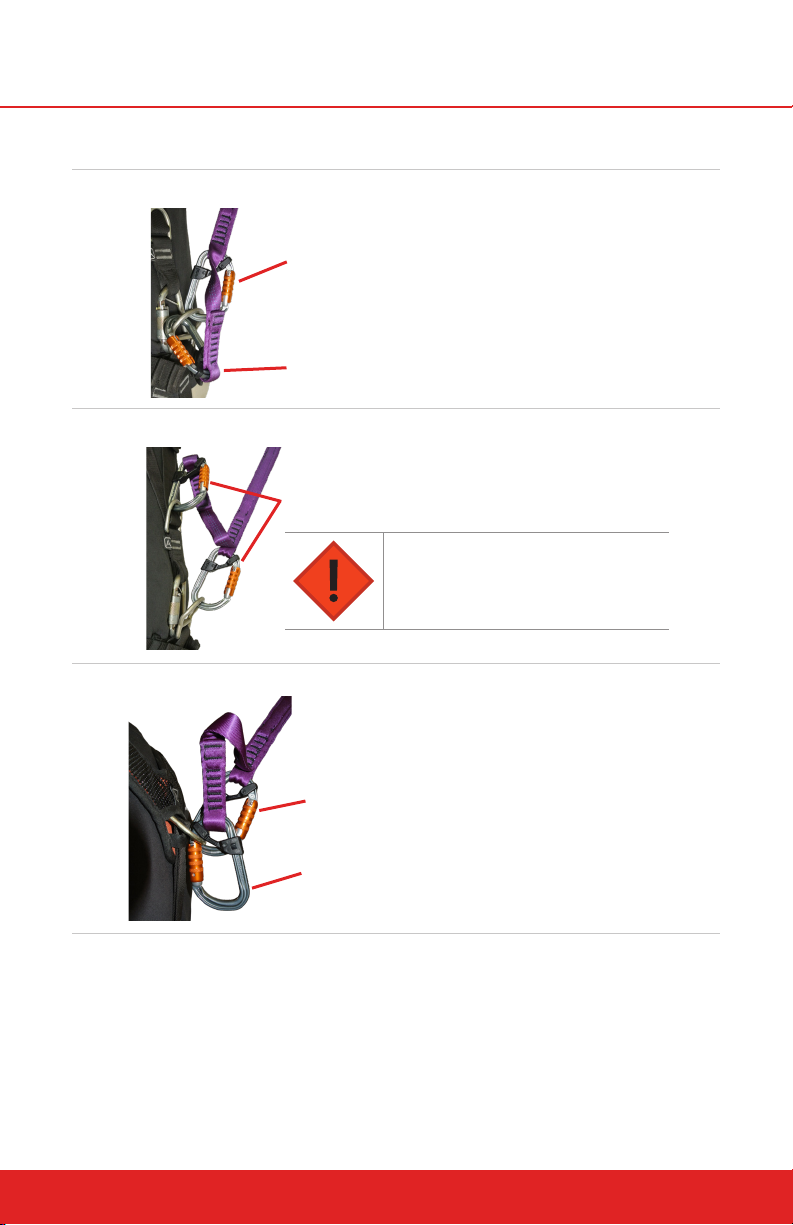
9.3 Proper Harness Connections
WAIST CONNECTION
Primary carabiner on waist attachment with gate
facing away from participant.
Secondary carabiner on waist attachment with gate
opposite primary carabiner.
CHEST AND WAIST CONNECTION
Both carabiners on separate attachment points with gate
facing away from participant. Primary carabiner connected
lower than secondary carabiner.
DO NOT REVERSE THE CONNECTION.
DORSAL CONNECTION
Primary carabiner on dorsal attachment with gate
facing away from participant.
Secondary carabiner on dorsal attachment with gate
opposite primary carabiner.
9.4 Carabiner Operation
If not using the carabiners supplied with the QuickFlight Free Fall Device, refer
to the appropriate connector’s User Instructions.
The supplied carabiners use a triple-action gate and are opened by sliding the
gate’s collar, rotating the gate’s collar, and then pushing the gate toward the
center of the carabiner.
headrushtech.com | +1-720-565-6885
31
Page 32
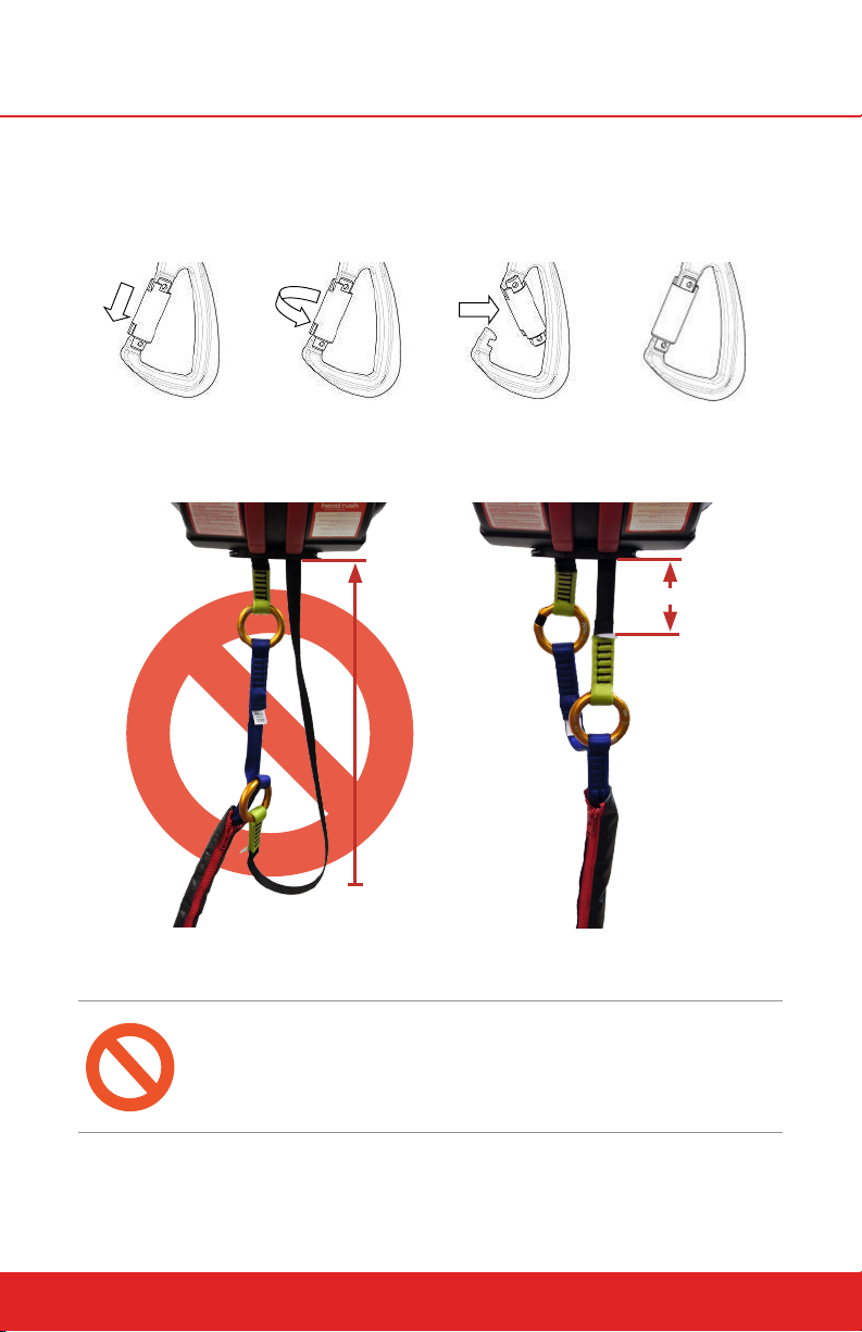
The carabiners are closed by releasing the gate and allowing it to snap shut,
ensuring the collars have rotated back and slid back to their fully locked position. Ensure that no clothing, webbing, incompatibly shaped D-rings, or other
objects are obstructing the gate or its latching function.
Step 1 – Slide Step 2 - Twist Step 3 – Depress Step 4 – Release
9.5 Proper Webbing Retraction
<0.3m (1 ft)
>0.3m (1 ft)
INCORRECT
DO NOT ATTEMPT TO ASSIST THE RETRACTION OF THE WEBBING FOR ANY
REASON. DOING SO COULD LEAD TO A DANGEROUS BINDING OF THE WEBBING
WHICH CAN ABRUPTLY SHORTEN THE LIFE OF THE WEBBING.
32
headrushtech.com | +1-720-565-6885
CORRECT
Page 33
10.0 INSPECTION AND MAINTENANCE
10.1 Annual Recertification
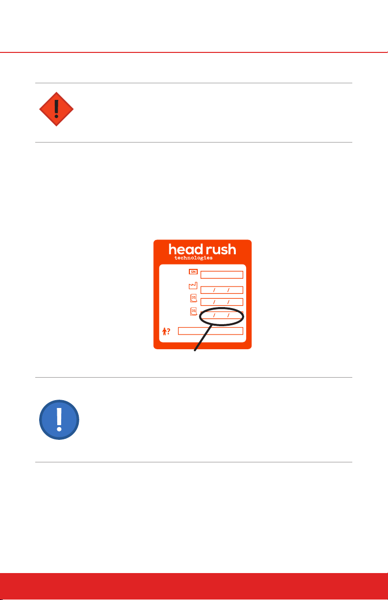
DO NOT OPERATE AFTER THE DATE SHOWN ON THE CERTIFI
CATION LABEL
Operation of a QuickFlight Free Fall Device without a current Certification
Label visible is strictly forbidden. Severe bodily injury or death may occur.
The QuickFlight Free Fall Device requires an annual service and recertification
inspection to be carried out by an authorized Head Rush Technologies service
agent.
The Certification expiration date is shown on the Certification Label located
on the side of the front casing. Dismount the Free Fall Device and return to the
Manufacturer at the address shown at the back of this Manual or to an Authorized Service Center prior to the expiration date.
SERIAL NUMBER:
MANUFACTURE DATE:
RECERTIFICATION DATE:
NEXT RECERT REQUIRED:
BY:
10024-02
Do not use the Free Fall Device after date shown here.
ALL QUICKFLIGHT FREE FALL DEVICES MUST BE INSPECTED AND MAINTAINED
IN ACCORDANCE WITH THIS MANUAL. FAILURE TO PERFORM SCHEDULED
MAINTENANCE AND INSPECTIONS ON THE QUICKFLIGHT FREE FALL DEVICE
MAY RESULT IN SERIOUS INJURY OR DEATH. DO NOT ATTEMPT TO CARRY OUT
ANY MAINTENANCE, REPAIR, OR SERVICE ACTIONS NOT DETAILED IN THE USER
MANUAL. ANY UNAUTHORIZED MAINTENANCE, REPAIR, OR MODIFICATIONS TO
THE QUICKFLIGHT FREE FALL DEVICE WILL COMPROMISE SAFETY, RENDER THE
DEVICE NOT FIT FOR USE, AND VOID THE WARRANTY.
10.2 Scheduled Maintenance
The following inspection and service actions must be carried out by the operator or operator-trained sta. All personnel performing these actions must be
trained in the correct procedures and deemed competent to do so.
headrushtech.com | +1-720-565-6885
33
Page 34
NO UNAUTHORIZED SERVICING
Do not attempt to carry out any maintenance, repair or service actions not
detailed in the User Manual.
Any unauthorized maintenance, repair or modifications to the Free Fall
Device will compromise safety, render the unit not fit for use, and void the
warranty provisions.
NOTE
Service in a clean environment. If Free Fall Device has been removed from
its operational location for service, ensure that the service area is clean
and free from contaminants.
Ensure unit is securely placed on a sturdy work table and that side covers
are not subject to damage.
10.2.1 SAFETY PRECAUTIONS
HEAVY OBJECT – 25 KG (55 LBS)
Ensure the Free Fall Device is secured during service to prevent accidental
damage or injury from dropping.
CAUTION – SPRING LOADED PARTS
The webbing assembly is spring loaded and will rapidly return into the
device if released. This may result in damage or injury.
MAGNETIC PARTS
The Free Fall Device contains strong magnets. Always ensure working environment is free of loose ferrous materials. Ingress of metal objects may
compromise QuickFlight operation.
Always use genuine Head Rush replacement parts; any modifications without
the expressed written consent of Head Rush Technologies are not allowed.
Third party components should be inspected and serviced in accordance with
that manufacturer’s instructions. Supplemental instructions, demonstration
videos, and inspection logs are available at headrushtech.com.
34
headrushtech.com | +1-720-565-6885
Page 35

10.3 Daily Inspection
The daily webbing inspection must include at least a visual inspection sucient to evaluate the wear and integrity of the device’s webbing. Please see
“Webbing Wear” below for a detailed description of when a webbing should be
taken out of service. The inspection may be performed from the ground if the
webbing can be adequately inspected.
10.3.1 UPPER WEBBING INSPECTION
INSPECT BOTH UPPER WEBBING LINES DAILY IN ACCORDANCE
WITH THE FOLLOWING INSTRUCTIONS.
The Upper Webbing lines in the QuickFlight are consumable wear components
which require daily inspection and periodic replacement when they show signs
of wear, damage, or contamination. More frequent inspection may be required
for high throughput facilities or when operating in harsh environments. Refer
to the Upper Webbing Wear Tables below for examples of acceptable and unacceptable wear of QuickFlight and QuickFlight XL Upper Webbing lines. These
tables do not include all possible types of wear or damage. If in doubt, remove
webbing from service. Webbing must be removed from service if it does not
pass inspection. Refer to the Upper Webbing Wear Troubleshooting Table for
possible causes of accelerated webbing wear. Continued use of webbing beyond stated limits may result in separation, disconnecting the Participant from
the QuickFlight Free Fall Device.
To inspect the Upper Webbing lines, simultaneously extract the entire length of
both lines from the device and carefully examine both edges and faces of each
webbing for wear or damage including:
Damage to stitching
Cuts to the face or edges
UV degradation including discoloration, fading, brittleness, or chalking
Hard fibers
Surface glazing or melting appearance
Permanent deformation or warping
Contamination from chemicals, dirt, grit, sand, dust, etc.
headrushtech.com | +1-720-565-6885
35
Page 36
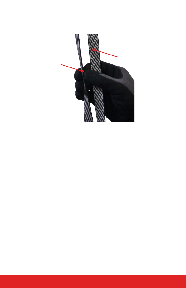
Edge
Face
Webbing Inspection Surfaces
36
headrushtech.com | +1-720-565-6885
Page 37
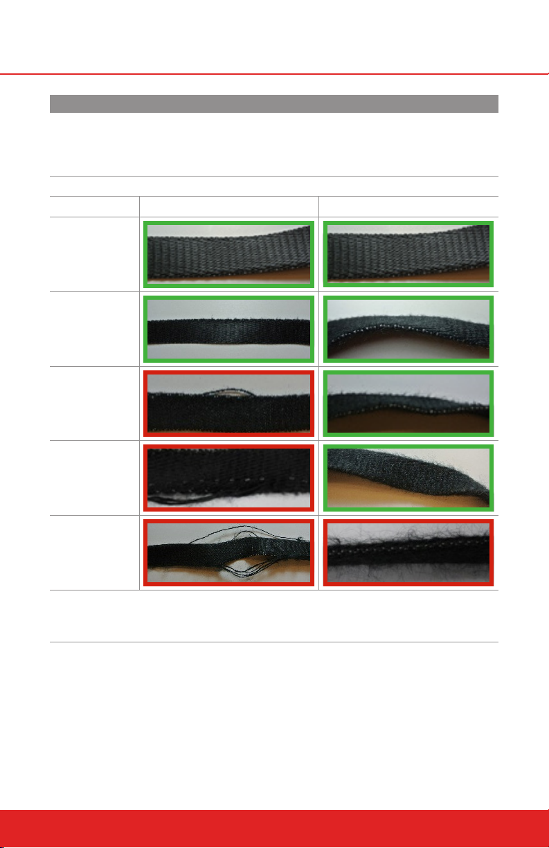
UPPER WEBBING WEAR TABLE - QUICKFLIGHT
Webbing pictures outlined in red in the tables below show webbing that
MUST be taken out of service and replaced immediately to continue using
the QuickFlight Free Fall Device. The green outlined photos show webbing
that can be kept in operation.
QuickFlight
Degree of Wear Side Wear Face Wear
NEW
STAGE 1
STAGE 2
STAGE 3
STAGE 4
MOLDY WEBBING
Any webbing showing signs of mold should be taken out of service.
headrushtech.com | +1-720-565-6885
37
Page 38
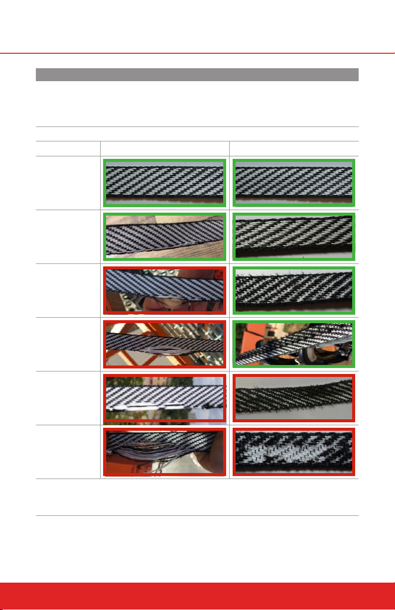
UPPER WEBBING WEAR TABLE - QUICKFLIGHT XL
Webbing pictures outlined in red in the tables below show webbing that
MUST be taken out of service and replaced immediately to continue using
the QuickFlight Free Fall Device. The green outlined photos show webbing
that can be kept in operation.
QuickFlight XL
Degree of Wear Side Wear Face Wear
NEW
STAGE 1
STAGE 2
STAGE 3
STAGE 4
STAGE 5
MOLDY WEBBING
Any webbing showing signs of mold should be taken out of service.
38
headrushtech.com | +1-720-565-6885
Page 39

WEBBING WEAR TROUBLESHOOTING TABLE
Symptoms Potential Causes Potential Solutions
Encourage Participants to step o the
platform rather than jumping out. Participants should also jump vertically. Flailing
motions (swinging arms and legs, leaning
forward/back, etc.) can create more lateral
movement.
Inspect nozzle for burrs and other dam-
age. If damage is found, replace nozzle.
Ensure that the QuickFlight is mounted
according to the Operator Manual. Make
sure that the QuickFlight is not angled.
Always mount QuickFlight vertically with
nozzle pointed down.
Cover the QuickFlight when not in use.
Wipe the webbing with a dry cloth daily,
after use.
Move the obstruction so that it does not
interfere with QuickFlight operation.
Parts and webbing wear over time with
normal operation, replace webbing as
necessary.
Remove QuickFlight at the end of day or
cover device and webbing after use.
Ensure that the RipCord webbing is
installed with the OPA end toward the
QuickFlight device. Coach Participants to
hold only the hand grip of the RipCord
webbing.
Whenever using the QuickFlight in wet
conditions, take the device down at the
end of the day, extend the webbing in a
sanitary environment, and allow webbing
to dry outside of the device. Do not store
in wet condition. Do not use heat to dry
webbing.
WEBBING FACE
WEAR
SIDE WEAR
& LOOP
FAILURE
UV FADED
WEBBING
JACKET
DAMAGE
WEBBING IS
MOLDY/
DISCOLORED
Participants are swing-
ing excessively as they
descend
Foreign objects, includ-
ing dirt and/or dust have
introduced damage to
nozzle stainless steel
surface
QuickFlight is mounted
incorrectly
Foreign objects, includ-
ing dirt and/or dust have
introduced damage to
webbing assembly
Webbing is rubbing on
obstruction
Normal use of QuickFlight
Sun is damaging webbing
Participants are pulling
down on QuickFlight
jacket as they jump
Webbing is not being
dried after being used in
wet conditions
headrushtech.com | +1-720-565-6885
39
Page 40
10.3.2 RIPCORD WEBBING INSPECTION
The RipCord Webbing does not wear significantly under normal operation,
but requires daily inspection for damage and degradation. Webbing must be
removed from service if it does not pass inspection. Continued use of webing
beyond stated limits may result in separation, disconnecting the Participant
from the QuickFlight Free Fall Device.
To inspect the RipCord Webbing, examine the entire length of the RipCord
Webbing from Webbing Connection Rings to Carabiners and carefully examine
the webbing and bar tacks for wear or damage including:
Loose stitching or damage to stitching
Cuts or abrasion damage to any part of the webbing assembly
UV degradation including severe discoloration, fading, or chalking. Refer
to the RipCord Webbing Degradation Table for replacement criteria due
to UV degradation.
Wear or damage to the Webbing Connection Rings or Carabiner attach-
ment loops
Hard fibers
Permanent deformation or warping
Contamination from chemicals, dirt, grit, sand, dust, etc.
The following mandatory checks must be performed each time the RipCord
Webbing is inspected:
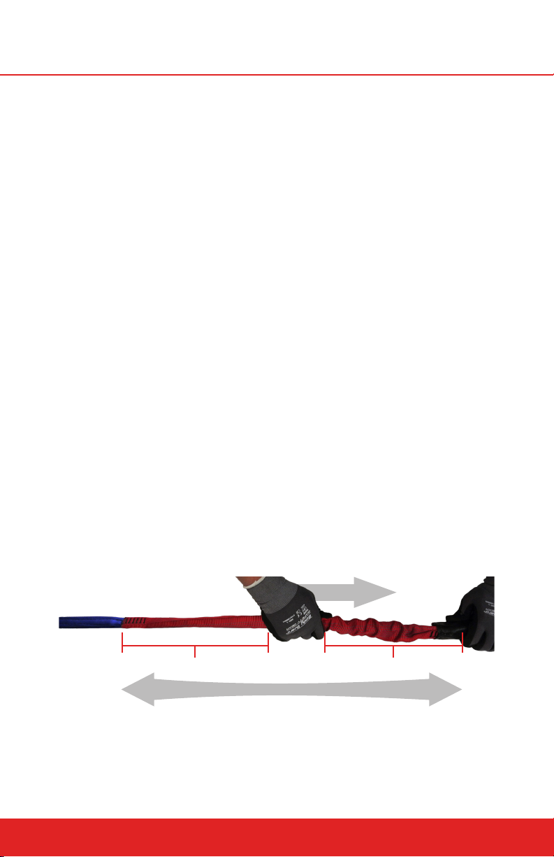
Bungee Integrity - Hold the Carabiner end of the RipCord stationary
and pull the bungee section tight. Check that the webbing covering the
bungee section remains slack while the internal webbing is tight. If the
outer webbing pulls tight, replace the RipCord.
Pull on Bungee Sheath
Stretched Bungee Sheath
Stretch Entire RipCord Webbing
RipCord Bungee Inspection
Slack Bungee Sheath
Overload Protection Assembly - Inspect the OPA section of the Rip-
Cord Webbing, ensuring that the OPA is fully contained within the OPA
Jacket. Open the OPA Jacket and inspect the internal webbing, bar
40
headrushtech.com | +1-720-565-6885
Page 41
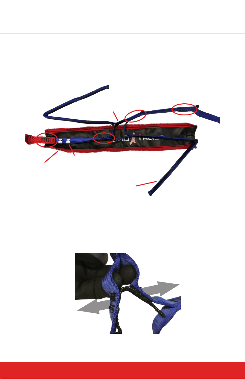
tacks, and stitching for damage. Check that the OPA Jacket is not dam-
aged and that webbing is still clamped to the OPA Jacket and positioned
so that the Jacket is centered between the bar tacks at the ends of the
OPA section.
BAR TACKS
(circled in red)
Inspect for damage and
stitching damage.
JACKET
Inspect for damage.
ACTIVATION STRIP
Inspect for continuity
and stitching damage.
CLAMPS
Inspect for good connection to webbing.
WINGS
(both sides)
Inspect for torn
threads.
RipCord OPA Inspection
Activation Strip - With the OPA Jacket open, find the Activation Strip
and check it for structural integrity by pulling outward on the colored
OPA webbing. Inspect the stitching for any broken threads. If broken
threads are found, replace the RipCord. Reinstall the OPA into the OPA
Jacket and close the zipper.
Activation Strip Inspection
headrushtech.com | +1-720-565-6885
41
Page 42
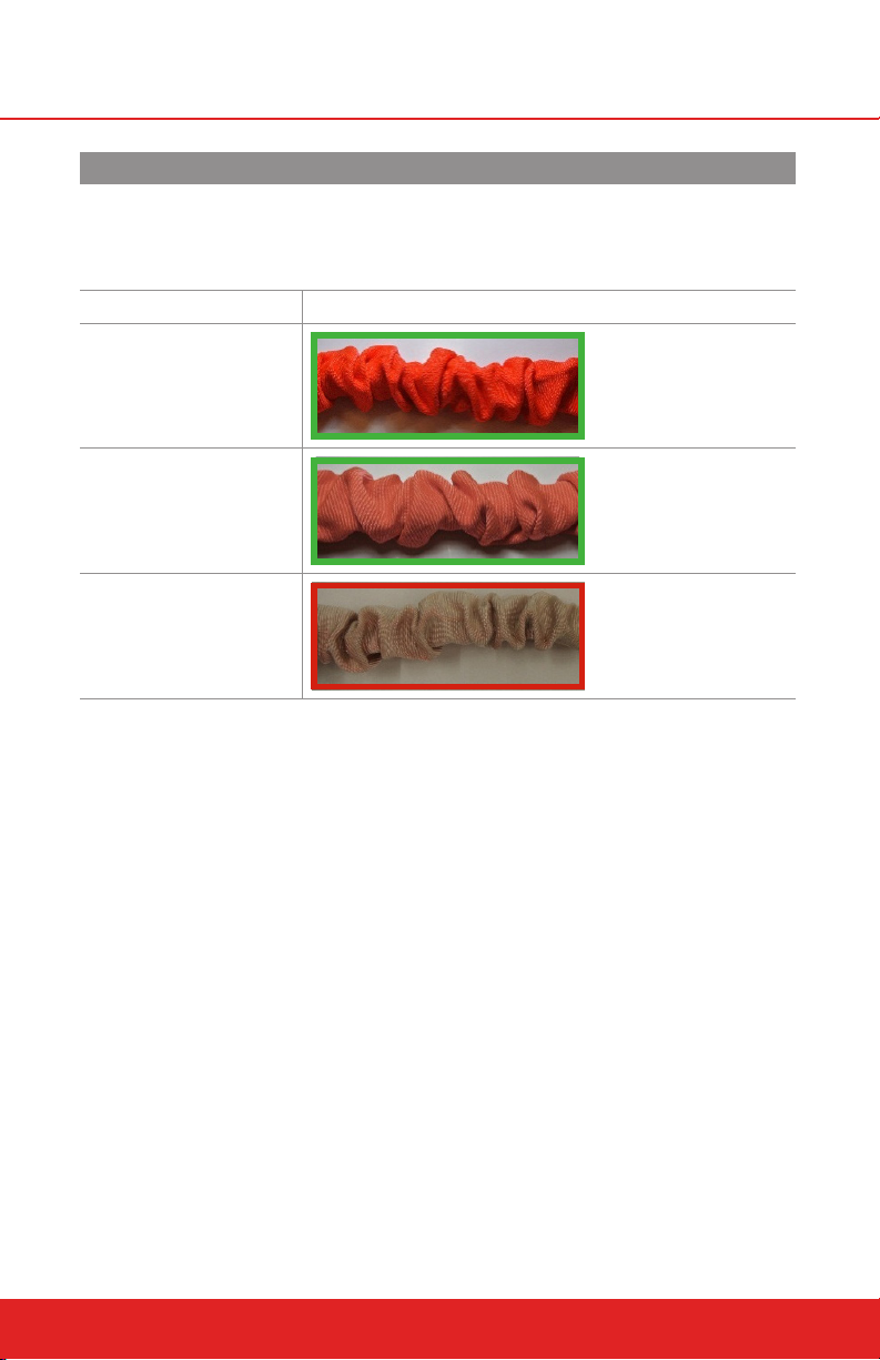
RIPCORD WEBBING DEGRADATION TABLE
Webbing pictures outlined in red in the tables below show webbing that
MUST be taken out of service and replaced immediately to continue using the
QuickFlight Free Fall Device. The green outlined photos show webbing that
can be kept in operation.
Degree of Wear UV Damage
NEW
STAGE 1
STAGE 2
10.4 Weekly Inspection
Once weekly, the condition of the device casing and side covers should be
visually inspected for damage or corrosion. The weekly inspection may be
carried out with the unit in place or removed to a sturdy work table. If operating in a salty or harsh environment, refer to Section: Side Cover Replacement
to remove the side covers and visually inspect the internal components for
corrosion. If red rust is found, the device should be immediately taken out of
service and returned for recertification. White scaling is acceptable and does
not require recertification. Reinstall the side covers after inspection.
The results of the Weekly Inspection should be documented on an inspection log. Weekly inspection logs are available for download at: https://headrushtech.com/service/inspection-logs.html.
1. Device Condition - Visually inspect the exterior of the QuickFlight casing
for damage, corrosion, loose fittings and fasteners. Verify that all safety
labels are in place and legible. Verify that the side covers are in place.
2. Device Mount - Inspect the QuickFlight mounting points and structure
anchor points for damage and ensure device and mount are suitably
secured.
42
headrushtech.com | +1-720-565-6885
Page 43

3. Mounting Hardware - Check that all hardware used to connect the
QuickFlight mounting points to the structure anchor points is in operational condition, secure, and free of corrosion.
4. Webbing Extension and Retraction - Check that the webbing extension
and retraction is smooth and maintains resistance throughout its range.
5. Upper Webbings - Simultaneously, fully extend both Upper Webbing lines
from the QuickFlight device. Check the condition of the lines, looking for
damage or discoloration. Refer to Section: Upper Webbing Inspection
for replacement criteria. If worn or damaged, replace with a new Upper
Webbing assembly.
6. RipCord Webbing - Check the condition of the RipCord Webbing includ-
ing the Overload Protection Assembly, looking for damage or discoloration. Refer to Section: RipCord Webbing Inspection for procedures and
replacement criteria. If worn or damaged, replace with a new RipCord
Webbing assembly.
7. RipCord Connection Hardware - Check that the Webbing Connection
Rings used to connect the QuickFlight RipCord Webbing to the QuickFlight Upper Webbings are both fully closed and tightened according to
the manufacturer’s instructions. Inspect the rings for damage and replace
if necessary. Head Rush Technologies allows the use of the Petzl Ring
Open only to connect the RipCord Webbing to the Upper Webbings.
8. Participant Connection Hardware - Inspect the condition of the carabin-
ers or other applicable Participant Connection Hardware, checking for excessive wear, damage, and correct operation of the locking mechanisms.
If a carabiner gate does not automatically lock, lubricate the carabiner
with dry graphite or dry PTFE based lubricant only until fully operational.
Do not allow lubricant to come in contact with any webbing line. If full
functionality of the locking mechanism cannot be restored, replace the
carabiner.
IF A CARABINER IS DAMAGED OR UNSERVICEABLE, ONLY AN EN 362 CERTIFIED
TRIPLE LOCKING CARABINER WITH LANYARD KEEPER MAY BE USED AS A RE
PLACEMENT CARABINER. HEAD RUSH TECHNOLOGIES RECOMMENDS THE USE
OF THE PETZL AM’D CARABINER WITH CAPTIV LANYARD KEEPER.
9. Lanyard Keepers - Inspect the Lanyard Keepers, checking that they are
not cracked or damaged, and that they maintain proper positioning of
each Carabiner on the ends of the RipCord Webbing. Replace damaged or
non-functional Lanyard Keepers.
headrushtech.com | +1-720-565-6885
43
Page 44
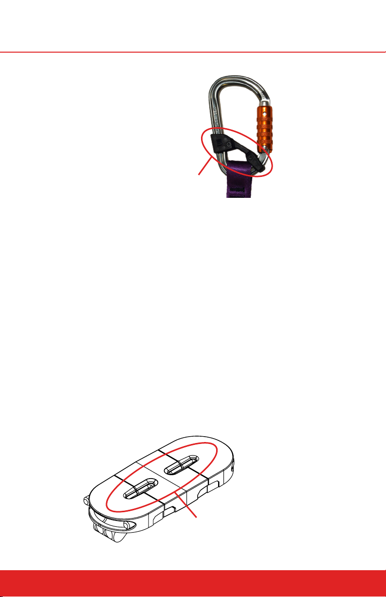
Check for cracks or damage.
Inspection of Lanyard Keeper
10.5 Bi-Annual Inspection
The QuickFlight Free Fall Device requires an in depth six (6) month inspection
by the Operator to maintain its safe and ecient operation. For the six monthly
inspections the unit must be dismounted and removed to a sturdy work table.
10.5.1 INSPECTION PROCEDURE
1. Dismount the Free Fall Device (refer to Installation Instructions).
2. Clean Free Fall Device using a clean cloth.
3. Carry out Steps 1 through 6 of the ‘Weekly Inspection’.
4. Remove the Nozzle – Refer to ‘To remove the nozzle assembly” section
below.
5. Inspect Nozzle Assembly for the following:
Excessive wear to slot, which could aect retraction of the webbing.
Splitting, cracking and deformation.
Correct fit in housing.
44
Check nozzle for excessive wear
around slots.
Inspection of Nozzle
headrushtech.com | +1-720-565-6885
Page 45
ANNUAL RECERTIFICATION
OPERATION OF THE QUICKFLIGHT FREE FALL DEVICE WITHOUT A CURRENT
CERTIFICATION LABEL VISIBLE WILL RENDER THE DEVICE NOT FIT FOR USE
AND VOID THE WARRANTY. CONTINUED OPERATION PAST THE “NEXT RECERT
REQUIRED” DATE MAY RESULT IN SERIOUS INJURY OR DEATH.
The QuickFlight Free Fall Device requires an annual service and recertification
inspection to be carried out by an authorized Head Rush Technologies Authorized Service Agent. The QuickFlight device should be packaged in its original
protective foam and box in order to safeguard the device from damage during
shipping.
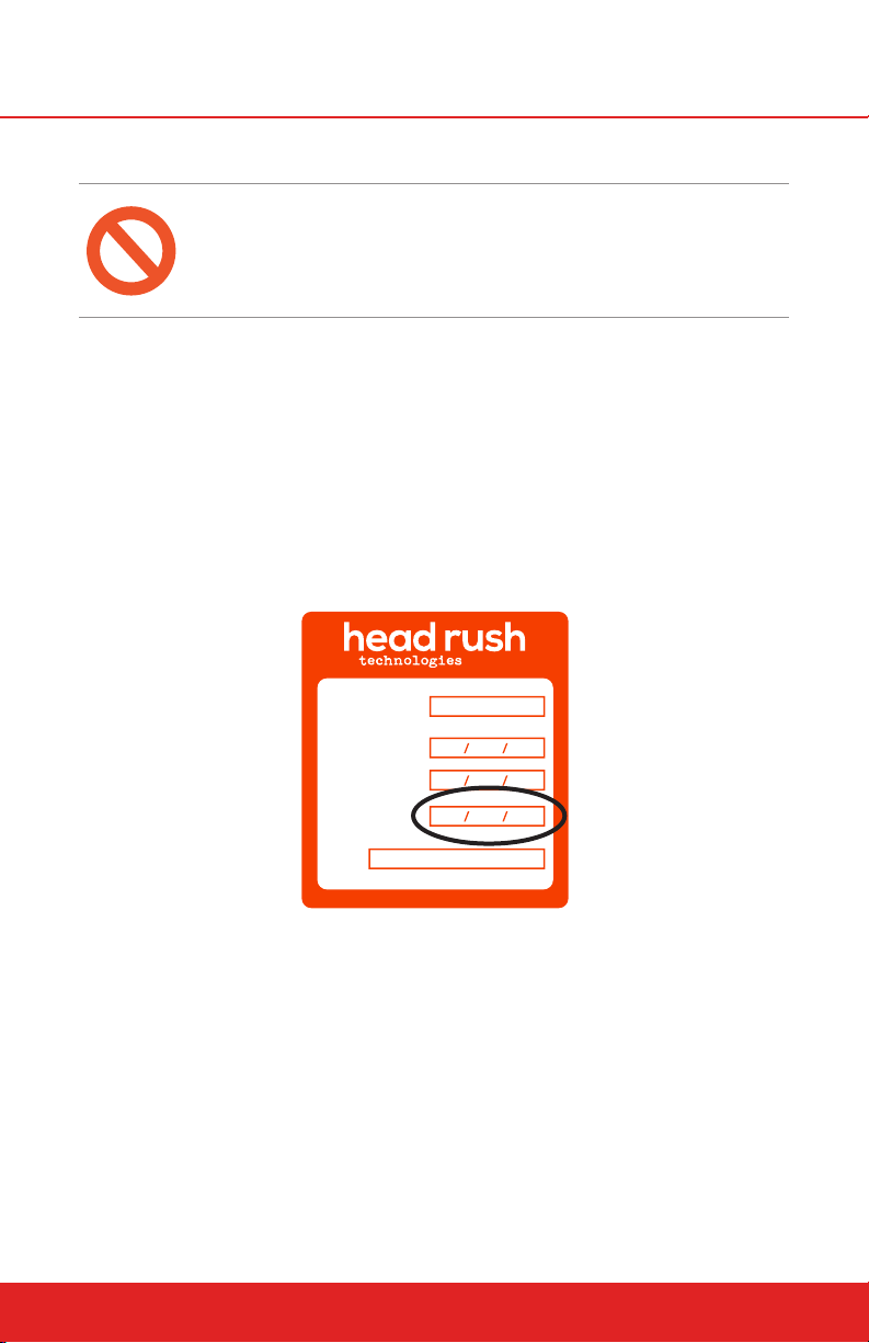
The Certification expiration date is shown on the Certification Label located on
the device casing. Dismount the QuickFlight Free Fall Device and return to an
Authorized Service Center prior to the Next Recertification Date shown. Document the orientation and connection details prior to dismounting the device to
aid reinstallation.
SERIAL NUMBER:
MANUFACTURE
RECERTIFICATION
DATE:
DATE:
NEXT RECERT
REQUIRED:
BY:
10024-01
“Next Recert Required” Date Shown Here
10.6 Upper Webbing Replacement
Replacement of an Upper Webbing assembly may be carried out with the
QuickFlight in place or removed and secured to a workbench.
headrushtech.com | +1-720-565-6885
45
Page 46
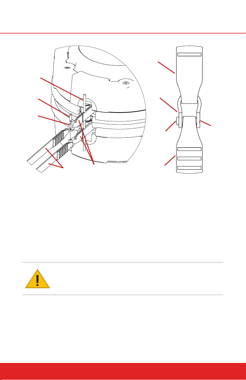
Holding Pin
Drum Lead
Shackle Pin (2)
Shackle (2)
Upper
Webbing (2)
Drum Lead
(2)
Drum Lead Diagram
Shackle
Shackle Pin
Upper Webbing
Pin Flush
with Shackle
To replace an Upper Webbing:
1. Disconnect the Webbing Connection Ring from the Upper Webbing being
replaced.
2. Remove the nozzle assembly.
3. Simultaneously extract the entire length of both Upper Webbings including their drum leads.
4. Insert a suitable holding pin through the loops in the drum leads above the
shackle. This will prevent the lines from retracting back into the device.
IF EITHER DRUM LEAD RETRACTS BACK INTO THE DEVICE, THE DEVICE WILL
REQUIRE SERVICE BY AN AUTHORIZED SERVICE CENTER.
5. Unscrew the shackle pin of the webbing to be replaced and remove the
webbing. Discard the old shackle pin. Cut o the ends of the used Upper
Webbing before discarding to ensure it is not accidentally re-used.
46
headrushtech.com | +1-720-565-6885
Page 47
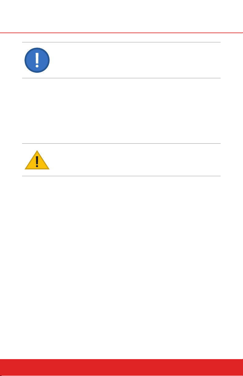
ALWAYS USE A NEW SHACKLE PIN PROVIDED WITH THE WEBBING REPLACE
MENT KIT. NEW SHACKLE PINS COME WITH THREAD LOCKING COMPOUND
THAT CAN ONLY BE USED ONCE.
6. Install the new Upper Webbing and new Shackle Pin, ensuring the shackle
loop is fitted to the drum lead and shackle pin to the end of the webbing.
Ensure that the new webbing assembly is correct for the device model,
mounting configuration, and RipCord configuration.
7. Tighten the shackle pin until fully seated.
8. Remove the holding pin and allow the Upper Webbing lines to slowly
retract without twisting until the drum leads and sewn webbing ends are
inside the device.
TWISTED WEBBING WITHIN THE DEVICE MAY CAUSE THE NOZZLE ASSEMBLY TO
DISCONNECT FROM THE DEVICE CASING, LEADING TO SUDDEN AND EXTREME
WEBBING WEAR, WEBBING SEPARATION, SERIOUS INJURY, OR DEATH.
9. Replace the nozzle assembly.
10. Allow the webbing lines to slowly retract into the device without twisting
while maintaining constant tension. Ensure the retraction force is smooth
and adequate resistance is felt.
11. Once the webbing lines are fully retracted, pull hard on both lines at once,
extracting a short length (~1m) of webbing. Repeat up to three times to
ensure that the dual webbings are equally stretched and tightly wound
onto the drum.
12. Ensure that one Upper Webbing is fully retracted and that the other Upper
Webbing is no more than 0.3m (1 ft) extracted from the nozzle.
13. Connect the colored end of the Upper Webbing to the Webbing Connection Ring that was previously disconnected, following the manufacturer’s
instructions to ensure that the Connection Ring is properly closed. Ensure
that there are no twists between the RipCord Webbing and the Upper
Webbings.
14. If necessary, reinstall the QuickFlight to its properly mounted position.
headrushtech.com | +1-720-565-6885
47
Page 48
10.7 Nozzle Replacement
The nozzle assembly is located on the QuickFlight device casing and provides guidance for the dual Upper Webbings during extraction/retraction. the
nozzle assembly is a wear component and will need to be inspected regularly;
replacement is on a conditional basis. Service of the nozzle assembly may be
carried out with the QuickFlight in place or removed and secured to a workbench.
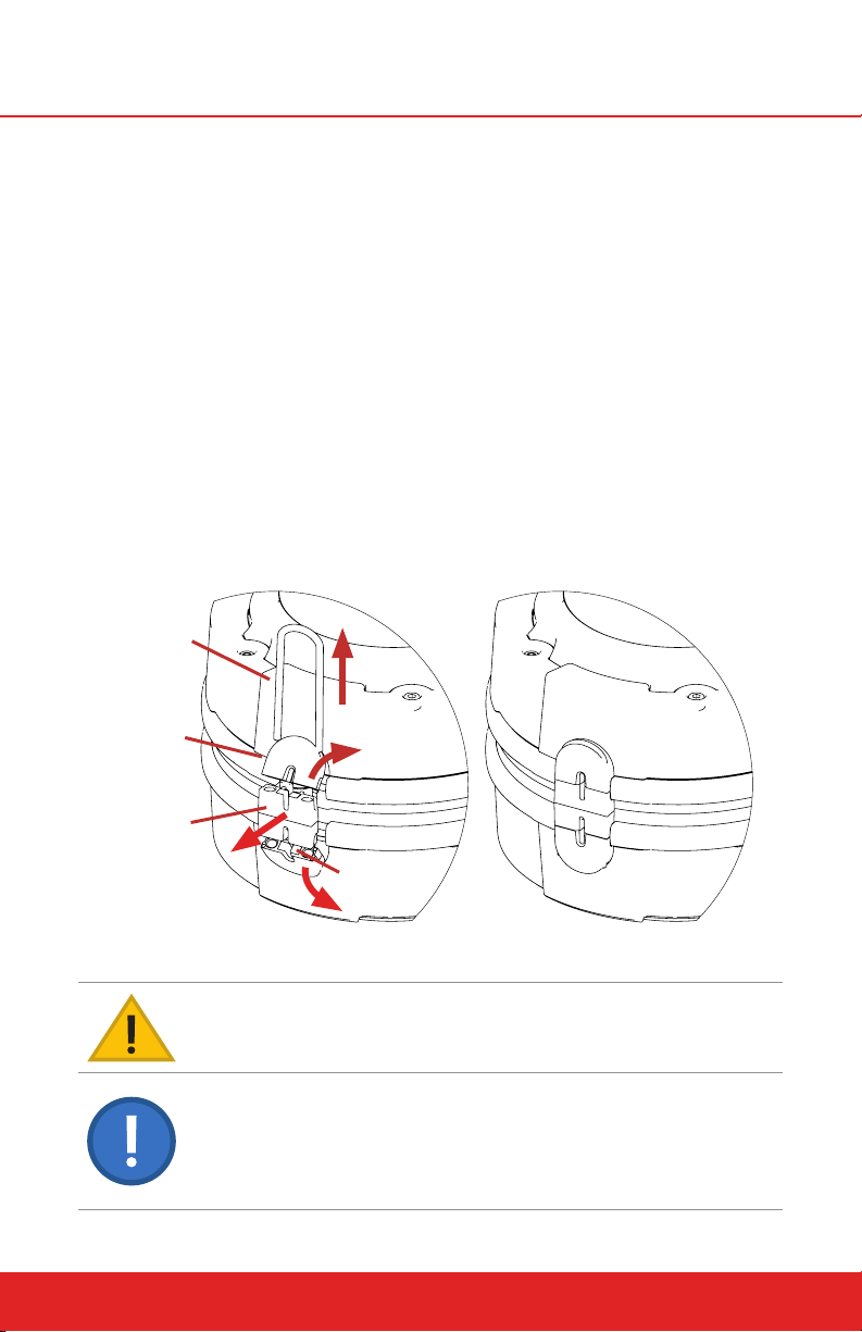
To remove the nozzle assembly:
1. Secure or hold the webbing lines to prevent them from retracting into the
device when the nozzle is removed.
2. Extract the U-shaped nozzle pin using a flat head screwdriver or comparable tool.
3. Remove the three nozzle pieces.
4. To re-install the nozzle assembly, reverse the above steps, ensuring that
the webbing lines do not become twisted.
Nozzle Clip
Nozzle
Housing
48
Central
Nozzle
Housing
Stainless Steel
Nozzle Insert
Nozzle Replacement Diagram (Webbing not shown)
DO NOT OPERATE THE QUICKFLIGHT FREE FALL DEVICE WITHOUT THE NOZZLE
ASSEMBLY PROPERLY INSTALLED.
NOZZLES ARE WEBBING SPECIFIC. QUICKFLIGHT DOES NOT USE THE SAME
NOZZLE AS THE QUICKFLIGHT XL. USE THE APPROPRIATE NOZZLE FOR YOUR
SPECIFIC MODEL. INCORRECTLY USING A QUICKFLIGHT NOZZLE WITH A
QUICKFLIGHT XL CAN RESULT IN ACCELERATED WEBBING WEAR. IF NOZZLE
REQUIRES REPLACEMENT ALWAYS REPLACE AS A MATCHED THREEPART SET
DO NOT MIX WORN AND NEW NOZZLE PIECES.
headrushtech.com | +1-720-565-6885
Page 49
10.8 Side Cover Replacement
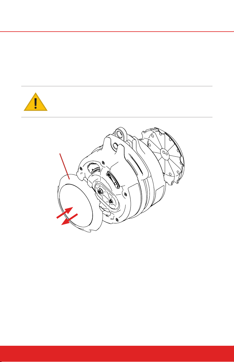
The QuickFlight Free Fall Device side covers are removable and simply snap
into place on the device casing. Remove side covers by placing a flat head
screwdriver under the edge of the cover and carefully levering it up. To replace, align the outer profile of the side cover with the profile of the casing and
snap into place.
DO NOT OPERATE THE QUICKFLIGHT FREE FALL DEVICE WITH SIDE COVERS
REMOVED.
Side Cover
Side Cover Replacement Diagram
headrushtech.com | +1-720-565-6885
49
Page 50
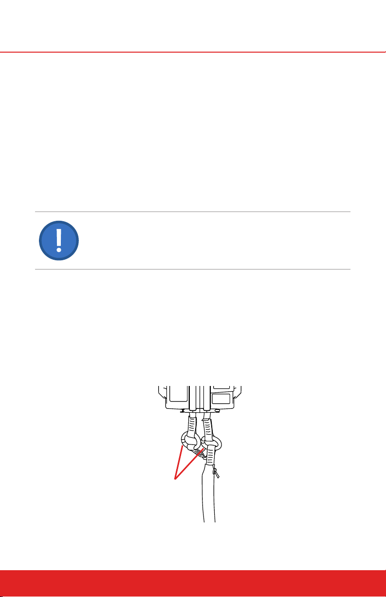
10.9 RipCord Webbing Replacement
Replacement of a RipCord Webbing assembly may be carried out with the
QuickFlight in place or removed and secured to a workbench.
To replace a RipCord Webbing:
1. Disconnect both Webbing Connection Rings from their respective Upper
Webbings.
2. Cut the connection points o of the RipCord Webbing to ensure it is not
accidentally re-used.
3. Discard the RipCord Webbing and all associated Webbing Connection
Rings, Carabiners, and other connectors unless the manufacturer’s instructions allow for longer-term use.
ALUMINUM CARABINERS AND RINGS HAVE A LIMITED LIFESPAN AND SHOULD BE
RETIRED FROM SERVICE WHEN THE RIPCORD WEBBING IS REPLACED.
4. Open the Webbing Connection Rings on the new RipCord Webbing.
5. Connect the Webbing Connection Rings so that they each join one RipCord attachment point to one Upper Webbing attachment point. Ensure
that the OPA end of the RipCord Webbing is attached to the Upper Webbings, and that the hand grip and carabiners are positioned away from the
device. It does not matter which Connection Ring goes to which Upper
Webbing.
6. Close the Webbing Connection Rings on the new RipCord according to the
Manufacturer’s instructions.
50
Webbing
Connection Rings
(see manufacturer’s
instructions)
Webbing Connection Ring Diagram
headrushtech.com | +1-720-565-6885
Page 51
10.10 Long Term Storage
If the QuickFlight Free Fall Device is to be placed into storage or left unused for
longer than two weeks, ensure the device and all webbing components are
clean and dry and protected from the environment. Ensure the Upper Webbings are fully retracted into the device. Always store in a clean, cool, and dry
environment, preferably in the original packaging. Upon re-installation of the
device, perform the Daily, Weekly, and Bi-Annual Inspections if appropriate.
After exposure to water or damp conditions, thoroughly clean and dry the
QuickFlight prior to storage. Ensure that the QuickFlight is not left with a wet
webbing inside the casing as this may result in corrosion of the device and
deterioration of the webbing. To dry the webbing / device, remove the side
covers and fully extend the wet webbing assembly and allow to completely dry
in a clean environment prior to storing the device. Ensure that debris does not
enter the device when side covers are removed. Re-install the side covers prior
to storing or using the device.
DO NOT STORE THE QUICKFLIGHT, UPPER WEBBINGS, RIPCORD WEBBING,
OR ASSOCIATED COMPONENTS IN A WET CONDITION. STORAGE MUST BE
IN A CLEAN, COOL, AND DRY ENVIRONMENT IN ACCORDANCE WITH THESE
INSTRUCTIONS.
NEVER USE HEAT TO DRY THE WEBBING OR DEVICE. DO NOT USE SOLVENTS
OR ABRASIVES WHEN CLEANING QUICKFLIGHT COMPONENTS, WEBBINGS, AND
ASSOCIATED EQUIPMENT.
Improper Operation
THE FOLLOWING SCENARIOS ARE NOT ALLOW
ABLE, MAY CAUSE DEVICE DAMAGE, AND CREATE
A DANGEROUS SCENARIO WHICH COULD RESULT
IN EQUIPMENT DAMAGE, SERIOUS INJURY, OR
DEATH.
Pulling webbing out of the device before descent for additional free fall.
Descending from the platform with a running start.
Descending on the device with a higher weight than the device maxi-
mum.
Using multiple devices simultaneously to accommodate weights above
the maximum.
Lowering more than one participant at a time. The QuickFlight Free Fall
Device is designed to lower only one participant at a time.
headrushtech.com | +1-720-565-6885
51
Page 52

10.11 Replacement Parts
Your QuickFlight Free Fall Device is fitted with a number of user replaceable
parts that may be refitted without the need to return the device to an authorized Head Rush Technologies Service Center. Always follow the Manufacturer’s instructions as detailed in this User Manual and any Part Replacement
Guide supplied when undertaking replacement of a part.
NOTE
For optimal performance of your QuickFlight Free Fall Device, only use
genuine QuickFlight parts and accessories.
To order replacement parts or accessories, contact your authorized Head Rush
Technologies Distributor or go to https://store.headrushtech.com.
10.12 Troubleshooting
Refer to http://headrushtech.com/troubleshooting for troubleshooting instructions or contact your authorized Head Rush Technologies Distributor or
Service Center.
10.13 Transportation
When shipping the QuickFlight Free Fall Device for recertification or
service, place it in the box with the bump out on the front cover facing up
and the white foam facing up.
To ensure safe shipment of your QuickFlight, it should only be shipped in
an authorized QuickFlight packaging (box and packing material). If you have
misplaced your original packaging, purchase replacement packaging from an
authorized Head Rush Technologies Distributor or Service Center, or online
at https://store.headrushtech.com. When shipping the unit back to an authorized Head Rush Technologies Service Center, place it in the box with the front
cover with bump facing UP and the white foam facing UP. You will be responsible for the cost of any damage and necessary repairs due to shipping your
QuickFlight in unauthorized packaging.
CARE FOR THE ENVIRONMENT
Reuse the original packaging when shipping Free Fall Device.
52
headrushtech.com | +1-720-565-6885
Page 53

11.0 MANUFACTURER’S DETAILS
For Recertification or unscheduled service or repairs, return your QuickFlight
Free Fall Device to your nearest Head Rush Technologies Authorized Service
Center or to the Manufacturer at the address shown below.
ADDRESS
Head Rush Technologies
1835 38th Street
Boulder, CO 80301
USA
To find a Service Center outside the U.S., visit headrushtech.com/distributors/
service-centers.
EU importers may apply their name and address on the device to comply with
government regulations next to the specification label.
CONTACT DETAILS
+1-720-565-6885
www.headrushtech.com
[email protected]
headrushtech.com | +1-720-565-6885
53
Page 54

REGISTER YOUR DEVICE
Get automatic updates on recertification and product information – visit
headrushtech.com/register
ANNUAL RECERTIFICATION IS REQUIRED
Please keep the shipping box for your device. For instructions on annual
recertification, visit headrushtech.com/recertification
+1-720-565-6885 www.headrushtech.com [email protected]
Oct 2019
 Loading...