

Page 1

ZIPSTOP
ZIP LINE
BRAKE
Installation, Operation & Maintenance Manual
Models: ZS125-08 / ZSIR150-20A
NOTE TO INSTALLERS
Always Read Instructions Before Use
Leave this manual attached to the zipSTOP Brake unit. The Installation, Operation
and Maintenance manual contains information relating to the proper use of the
zipSTOP and includes all product registration and warranty information. This document may only be removed by the end user prior to operation. Ensure that this
manual is readily available to operators at all times.
Head Rush Technologies zipSTOP Zip Line Brake Installation, Operation & Maintenance Manual
P/N 01170006604
Head Rush Technologies products are covered by a number of patents, including
U.S. Patents 8,490,751; 8,851,235; 9,016,435; 8,851,235 and D654,412 & corresponding patents/applications in the USA and in other countries worldwide.
Page 2

TABLE OF CONTENTS
1. SAFETY INFORMATION 7
1.1 Symbols Used in this Manual
2. EMERGENCY ARREST DEVICE EAD CONFIRMATION 8
3. SAFETY & INFORMATION LABELS 9
3.1 Location of Safety Labels
4. WARRANTY INFORMATION 10
4.1 Warranty Conditions
4.2 Customer Responsibility
5. SPECIFICATIONS 11
5.1 Introduction
5.2 zipSTOP Brake Unit, ZS125-08
5.3 zipSTOP Brake Unit, ZSIR150-20A
5.4 zipSTOP Brake Trolley, ZS125-08 and ZSIR150-20A
6. OPERATING PRINCIPLES 15
6.1 General
7. ZIPSTOP BRAKE ASSEMBLY 16
7.1 General
7.2 Unpacking the zipSTOP
7.3 Long Term Storage
7.4 Supplied Parts
7.5 General and Additional Parts Required
7.6 Redirection Pulleys
7.7 Traveler Assembly
7.8 Minimum Hardware Requirements
7.9 Redirection Line
7.9.1 Redirection Line Specifications: ZS125-08/ZS150-20A
8. ZIPSTOP BRAKE ASSEMBLY CONFIGURATION 22
8.1 General
8.2 Setup Variables, ZS125-08/ZSIR150-20A
8.3 Rider Arrival Speed
8.4 Rider Weight
8.5 Redirection Line Ratio
8.5.1 1:1 Ratio
8.5.2 2:1 Ratio
8.6 POSSIBLE SYSTEM CONFIGURATIONS (INFORMATIVE ONLY)
8.6.1 3:1 Ratio
8.6.2 Other Configurations
8.7 Zip Line Slope
8.7.1 Positive Slope Line
8.8 Flat Line
8.9 Negative Slope Line
8.10 Calculating zipSTOP Braking Distances
8.10.1 Definition of Terms
7
9
10
10
11
12
13
14
15
16
16
17
18
18
19
19
20
20
21
22
22
23
23
23
24
25
26
26
27
27
28
28
29
29
30
www.headrushtech.com | +1-720-565-6885
3
Page 3

8.11 zipSTOP Braking Distance Charts
8.12 Configuration Notes
8.13 zipSTOP Configuration Worksheet
31
31
33
9. ZIPSTOP BRAKE ASSEMBLY INSTALLATION 34
9.1 General
9.2 Safety Precautions
9.3 Primary Anchor Point
9.4 Secondary Anchor Point
9.4.1 Position of the Secondary Anchor Point
9.5 Redirection and Support Lines
9.6 Fitting zipSTOP Brake Unit
9.7 Fitting the Brake Trolley
9.8 Fitting Type I Pulley
9.9 Fitting Type II Pulley
9.10 Fitting Redirection Line
9.11.1 1:1 Redirection Ratio
9.11.2 2:1 Redirection Ratio
34
34
35
35
36
36
37
40
42
43
43
44
46
10. OPERATION OF ZIPSTOP 49
10.1 Safety Precautions
10.2 zipSTOP Operation as a Primary Brake
10.3 zipSTOP Operation as an EAD
10.4 Landing Areas
10.5 Operation During Extreme Weather Conditions
10.6 Resetting the Brake
10.7 Operational Retraction Spring Cycle Limit
49
50
50
50
51
51
52
11. TROUBLESHOOTING 53
11.1 Before You Call
57
12. RECERTIFICATION AND MAINTENANCE 58
12.1 General
12.2 Annual Recertification
12.3 Maintenance Service Schedule
12.4 Daily Inspections
12.4.1 Safety Precautions
12.4.2 Webbing Wear
12.5 Braking Line Replacement Procedure
12.6 Brake Trolley Inspection and Maintenance
12.7 Brake Unit Casing Inspection
12.8 Webbing Line Inspection
58
58
58
59
59
60
63
65
65
66
13. BRAKING DISTANCE CHARTS 67
13.1 How to Read Braking Distance Charts
13.2 1:1 Ratio – Metric, ZSIR150-20A
13.3 1:1 Ratio – Imperial, ZSIR150-20A
67
68
68
4
www.headrushtech.com | +1-720-565-6885
Page 4

13.4 1:1 Ratio – Metric ZS125-08
13.5 1:1 Ratio – Imperial ZS125-08
13.6 2:1 Ratio – Metric, ZS125-08
13.7 2:1 Ratio – Imperial, ZS125-08
13.8 3:1 Ratio – Metric
13.9 3:1 Ratio – Imperial
69
69
70
70
71
71
14. APPENDIX A: EAD WARRANTY/REGISTRATION FORM 72
14.1 Warranty Registration Form
72
15. APPENDIX B: ACCESSORIES AND REPLACEABLE PARTS 73
15.1 Accessories and Replacement Parts
15.2 Brake Trolley Catch Accessory
15.2.1 Specifications
15.2.2 Composition
15.2.3 Mounting/Installation
15.2.4 Operation
15.2.5 zipSTOP Brake Unit Side Cover Replacement
15.2.6 zipSTOP Brake Unit Nozzle Replacement
15.2.7 Removing Nozzle Assembly
15.2.8 To Refit the Nozzle Assembly:
15.2.9 Brake Trolley Bump Stop Replacement
15.2.10 Service Life
15.3 zipSTOP Pivot Mount
15.3.1 Composition
15.3.2 Mounting
15.3.3 Installation
15.3.4 Performance
15.3.5 Service Life
15.3.6 Inspection Procedures
73
73
74
74
74
77
80
80
80
81
82
82
82
83
83
84
86
86
87
16. APPENDIX C: EXAMPLE INSPECTION LOGS 88
17. MANUFACTURER’S DETAILS 90
www.headrushtech.com | +1-720-565-6885
5
Page 5

IMPORTANT SAFETY NOTICE
Zip Lining is a Dangerous Activity
Read Before Installation & Operation
Failure by the installer or operator to heed any and all instructions, warnings and cautions for the correct
installation, operation, care and maintenance of the zipSTOP may result in serious injury or death.
The zipSTOP Brake assembly, including zipSTOP Brake Unit Model ZB125-08B and ZSIR150-20A, zipSTOP
Brake Trolley Model ZT125-17 and all associated equipment are designed and specified for use in the recreational zip line industry as components of a well designed zip line brake system. Use of the zipSTOP components for any purposes other than that intended by the manufacturer is not permitted.
The zipSTOP is designed to be utilized as a Primary Brake or Emergency Arrest Device (EAD). When using the
zipSTOP as a primary brake, the installer MUST utilize an independent EAD to protect against operator error
and third party equipment failure. Design and installation of the zip line, including the complete braking system, is the responsibility of the installer or operator.
Owners and Operators of zipSTOP devices are responsible for the safety and supervision of any person using
the zipSTOP and are required to assure that proper installation and operation procedures are followed at all
times. Proper installation requires careful design and planning using zipSTOP and non-zipSTOP components.
Owners and Operators are encouraged to seek the advice of their zip line installer or a proper engineering
professional regarding the instructions in this Manual.
These instructions must be made readily available to the operator at all times. Prior to installation and use, all
owners, installers and operators must have read and shown to have understood all instructions, labels, markings,
and safety information pertaining to the installation, operation, care, and maintenance of the zipSTOP brake, its
component parts, and all associated hardware. Failure to do so may result in equipment damage, serious injury
and death.
Page 6

1. SAFETY INFORMATION
1.1 Symbols Used in this Manual
The following safety symbols are used throughout this manual to highlight potential danger to operators and
equipment. One or more precautions may be associated with practices and procedures described within this
manual. Failure to adhere to any precautions highlighted can result in equipment damage, serious injury and/
or death.
Ensure that you read and understand all safety related procedures related to the working environment and the
task you are undertaking.
DANGER
Indicates a hazardous situation exists that, if not avoided, will result in serious injury or death.
WARNING
Indicates a potentially hazardous situation that, if not avoided, could result in serious injury or
death.
CAUTION
Indicates a potentially hazardous situation that, if not avoided, may result in injury or equipment damage.
NOTE
Indicates an action that must be taken to ensure personal safety and prevent damage to
property or equipment.
CARE FOR THE ENVIRONMENT
Take care to minimize impact on the environment when carrying out this procedure.
www.headrushtech.com | +1-720-565-6885
7
Page 7

2. EMERGENCY ARREST DEVICE (EAD) CONFIRMATION
Zip lines using the zipSTOP Brake are required to use both primary and emergency arrest devices functioning
together to arrest the motion of passengers. The EAD must engage with no input from the passenger upon
failure of the primary arrest device.
This form must be initialed by the performing EAD installation technician, signed by a separate party and attached when mailing in the Warranty Registration Form; failure to do so may void your warranty .
I have read this manual prior to zipSTOP installation and use. INITIAL:
I am aware that an approved EAD is required prior to system use. INITIAL:
I certify that an approved EAD has been correctly installed prior to system use. INITIAL:
I have inspected the installation of the EAD and certify its functionality.
SIGNED: DATE:
8
www.headrushtech.com | +1-720-565-6885
Page 8
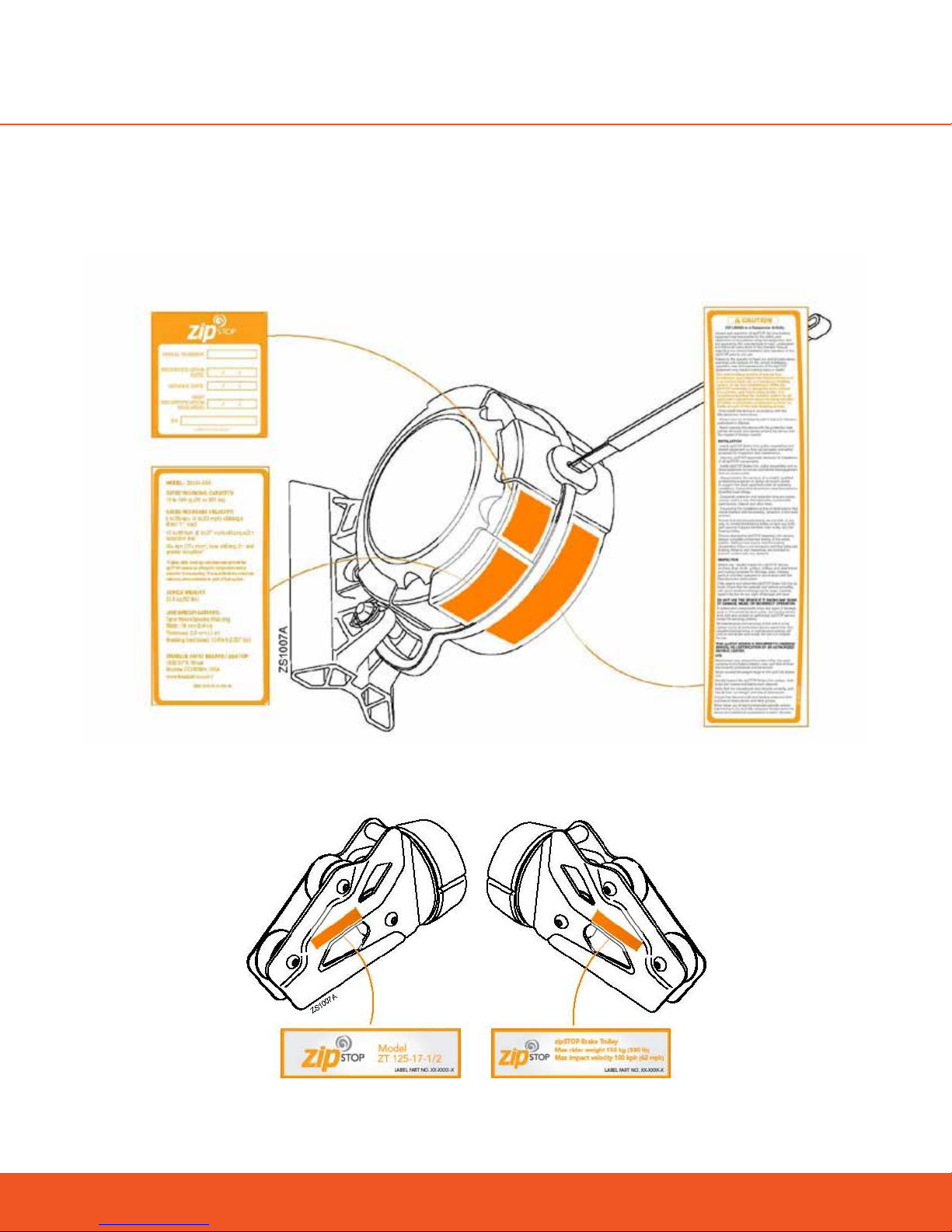
3. SAFETY & INFORMATION LABELS
Safety and Information Labels located on the zipSTOP components are not to be removed. Ensure labels are
in place and remain legible at all times.
3.1 Location of Safety Labels
www.headrushtech.com | +1-720-565-6885
Location of Labels – Brake Unit
Location of Labels – Brake Trolley
9
Page 9

4. WARRANTY INFORMATION
4.1 Warranty Conditions
Manufacturers sole warranty. The zipSTOP Brake assembly will be sold free from defects in materials and
workmanship, excluding field replaceable wear parts, for a period of one (1) year from date of purchase. This
warranty only applies to the original purchaser, and is contingent upon the owner/operator using and maintaining the device in accordance with the zipSTOP instructions, including the requirement to maintain annual
recertification as described in the Installation, Operation and Maintenance Manual.
THIS WARRANTY IS EXPRESSLY IN LIEU OF OTHER WARRANTIES, EXPRESS OR IMPLIED, AND ANY IMPLIED
WARRANTY OF MERCHANTABILITY OR FITNESS FOR A PARTICULAR PURPOSE IS HEREBY EXPRESSLY EXCLUDED.
The sole remedy for breach of said warranty or for any claim in negligence or strict liability in tort is the repair
or replacement of any defective parts at the discretion of the manufacturer. Such parts claimed to be defective shall be returned to the Head Rush Technologies Service Center, transportation prepaid, for inspection by
zipSTOP to determine to its satisfaction that said part(s) are defective.
This warranty is null and void if other than genuine parts are used, or if any modifications are carried out to the
zipSTOP Brake assembly or zipSTOP components without the expressed written permission of the manufacturer. No person, Agent or Distributor is authorized to give any warranty, other than the one herein expressed,
on behalf of the zipSTOP Company or to assume for it any liability pertaining to such products. The company
makes no warranties in respect to trade accessories or component parts which are not manufactured by the
company, same being subject only to such warranties, if any, as may be made by their respective manufacturers.
4.2 Customer Responsibility
The following items are considered to be the responsibility of the Customer and, therefore, are non-reimbursable under the terms of the warranty:
Correct installation of an EAD.
Sucient unmanned testing of the entire system.
Normal maintenance/routine services.
Normal replacement of service items.
Replacements required because of abuse, misuse or incorrect operation of equipment by the installer or
operator.
Field replaceable wear parts such as the nozzle, braking line, quick links, redirection line and pulleys,
brake trolley sacrificial bump stops, and sheaves supplied as zipSTOP branded parts.
Normal wear and tear due to use and exposure.
Strict adherence to the Installation, Operation and Maintenance Manual supplied, manufacturer’s instructions
and advice given by zipSTOP service technicians is also a condition of warranty (see Appendix A: EAD Warranty/Registration Form).
10
www.headrushtech.com | +1-720-565-6885
Page 10

5. SPECIFICATIONS
5.1 Introduction
The zipSTOP Brake assembly is a controlled braking force device designed specifically for use in the zip line
industry as a Primary or EAD at the end of zip line runs. The zipSTOP caters to a range of rider weights and
approach speeds, and oers a smooth, consistent braking force for all riders. The brake is designed to be
mounted to a primary and/or secondary anchor point to slow the decent of riders on a zip line. The primary
anchor point is exactly what it sounds like; it is the main attachment point for the brake. The secondary anchor point is the support point for the redirection lines and pulleys.
The zipSTOP Brake Unit is installed at the end of the zip line, usually on or adjacent to the terminal end. A
Secondary Anchor Point is normally required upstream of the landing area to provide support for the Redirection Line pulleys. Alternately a full-length secondary cable of sucient capacity can be installed to provide
support for the Redirection Line and associated pulleys.
The design of the zipSTOP allows for simple installation, and incorporates both an advanced self-regulating
brake unit and an automatic line reset. The patented braking mechanism delivers smooth deceleration and
is designed to minimize variations in the deceleration rate and stopping distance of both children and adults.
There are no friction parts in the brake mechanism, ensuring reliability remains high while maintenance and
operating costs are kept to a minimum.
Installation, inspection, operation and maintenance must be carried out in accordance with the instructions in
this manual to protect the longevity of the zipSTOP components.
Pictures in this manual are for reference purposes in terms of geometry and proposed redirection setup
configuration only. Mandated EAD may or may not be shown.
www.headrushtech.com | +1-720-565-6885
11
Page 11

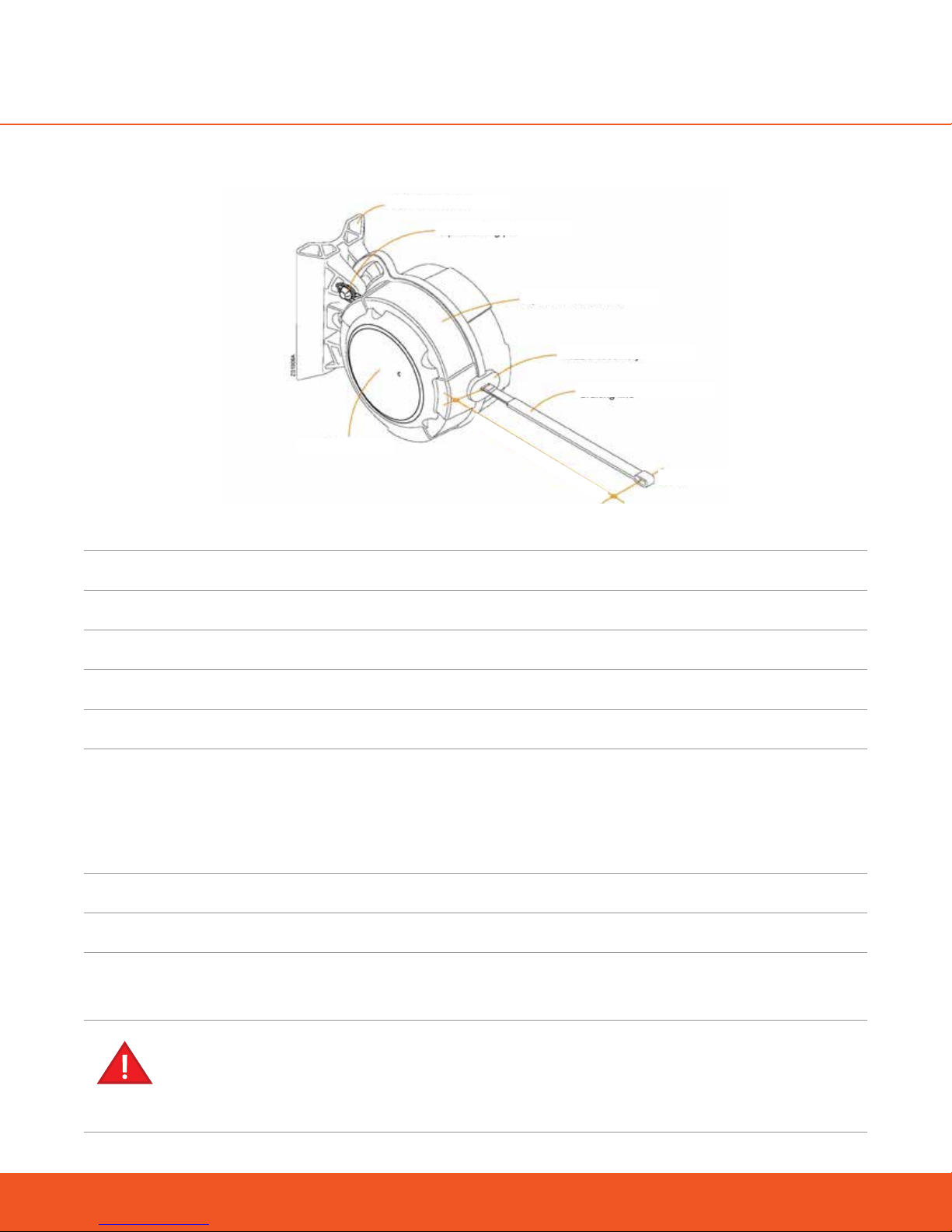
5.2 zipSTOP Brake Unit, ZS125-08
zipSTOP Mount
Top Mounting Pin
Fully Retracted - 400 mm (16”)
Side Cover
MODEL ZS 125-08B
CLASSIFICATION Zip Line Braking Device
zipSTOP Brake Unit
Nozzle Assembly
Braking Line
Pulley
DIMENSIONS 380 x 320 x 216 mm (15 x 12.6 x 8.5 in)
NET WEIGHT 23.5 kg (52 lbs)
OPERATING TEMPERATURE -10°C (14°F) to 40°C (104°F)
STORAGE TEMPERATURE -20°C (-4°F) to 60°C (140°F)
MATERIALS CASING Aluminium alloy
INTERNAL PARTS Zinc plated and stainless steel
NOZZLE Modified Acetal plastic with stainless insert
LINE 20 mm Nylon Spectra Braking Line
MAXIMUM LINE EXTENSION 12.5 m (41 ft)
RIDER WEIGHT RANGE 15 to 150 kg (33 - 330 lbs)
MAXIMUM SPEEDS 1:1 REDIRECTION RATIO 36 km/h (22 mph)
2:1 REDIRECTION RATIO 60 km/h (37 mph)
3:1 REDIRECTION RATIO* Contact Head Rush Tech
CUSTOM RATIO* Contact Head Rush Tech
*Higher speeds may be utilized with the custom Redirection Ratios, however braking distances will increase.
When planning a custom ratio, note that the automatic line reset may become compromised, requiring the
necessity for either manual reset or supplementary reset.
12
www.headrushtech.com | +1-720-565-6885
Page 12
5.3 zipSTOP Brake Unit, ZSIR150-20A
zipSTOP Mount
Top Mounting Pin
zipSTOP Brake Unit
Nozzle Assembly
Braking Line
Fully Retracted - 400 mm (16”)
Side Cover
MODEL ZSIR150-20A
CLASSIFICATION Zip Line Braking Device
DIMENSIONS 380 x 320 x 216 mm (15 x 12.6 x 8.5 in)
Pulley
NET WEIGHT 23.5 kg (52 lbs)
OPERATING TEMPERATURE -10°C (14°F) to 40°C (104°F)
STORAGE TEMPERATURE -20°C (-4°F) to 60°C (140°F)
MATERIALS CASING Aluminium alloy
INTERNAL PARTS Zinc plated and stainless steel
NOZZLE Modified Acetal plastic with stainless insert
LINE 20 mm Nylon Spectra Braking Line
MAXIMUM LINE EXTENSION 20 m (65 ft)
RIDER WEIGHT RANGE 15 to 150 kg (33 - 330 lbs)
MAXIMUM SPEEDS 1:1 REDIRECTION RATIO 60 km/h (37 mph)
ZSIR15020A THIS PRODUCT CAN ONLY BE USED WITH 1:1 REDIRECTION SETUPS
The zipSTOP IR (ZSIR150-20A) is NOT compatible with external redirection setups in any way. Installing
a redirection setup with the zipSTOP IR can create a very dangerous set of braking conditions that could
result in abnormally abrupt late braking.
www.headrushtech.com | +1-720-565-6885
13
Page 13

5.4 zipSTOP Brake Trolley, ZS125-08 and ZSIR150-20A
Redirection Line
Mounting Point
Upper Sheave
Lower Sheaves
MODELS ZT 125-17-1/2 – For use with 12.7 mm (½”) zip lines
ZT 125-17-3/4 – For use with 19 mm (¾”) zip lines
ZT 125-17-35/8 – For use with 15.9 mm (5/8”) zip lines
CLASSIFICATION Zip Line Brake Trolley
Bump Stops
DIMENSIONS 235 x 100 x 115 mm (9.3 x 3.9 x 4.5 in)
NET WEIGHT 1.3 kg (2.8 lbs)
MATERIALS CASING Aluminium alloy
WHEELS Steel
BUMP STOP Polyurethane
MAXIMUM SPEED 72 km/h (45 mph)
MINIMUM RIDER WEIGHT 15 kg (33 lbs)
MAXIMUM RIDER WEIGHT 150 kg (330 lbs)
14
www.headrushtech.com | +1-720-565-6885
Page 14

6. OPERATING PRINCIPLES
6.1 General
The zipSTOP Brake assembly is a controlled braking force device designed specifically for use as a Primary or
EAD at the end of zip line runs. The zipSTOP caters to a range of rider weights and approach speeds and oers
a smooth, consistent braking force for all riders. zipSTOP Brake performance relies on operators using the
correct equipment and operating the system in accordance with the instructions contained within this manual.
The zipSTOP Brake assembly consists of a zipSTOP Brake Unit, zipSTOP Brake Trolley, redirection pulleys and
associated Redirection Lines.
Pictures in this manual are for reference purposes in terms of geometry and proposed redirection setup
configuration only. Mandated EAD may or may not be shown.
Cable Clamps &
Primary
Mount
Redirection
Line Support
Quick Links
Redirection Line
Overhead Line
Redirection Pulley
Brake Line Extension
zipSTOP Brake Line
zipSTOP Brake Unit
Arrest Zone
Typical zipSTOP Installation
Zip Line
Brake Trolley
Rest Position
The zipSTOP Brake Unit is located at the zip line terminal end, normally adjacent to the landing area. It is
connected via a redirection pulley and Redirection Line setup to the zipSTOP Brake Trolley.
The Brake Trolley is located on the zip line and when idle (zipSTOP Braking Line fully retracted) will be
positioned at the start of the rider Arrest Zone (Reset Position). The approaching rider trolley contacts
the Brake Trolley, moving it down the zip line. As the Brake Trolley moves into the Arrest Zone it extends
the Braking Line out of the zipSTOP Brake Unit via the Redirection Line. As the Braking Line extends out
of the zipSTOP Brake Unit, the eddy current brake in the unit is activated, controlling the rate of deceleration and slowing the rider in a smooth manner.
Once the load is removed from the Brake Trolley, the return mechanism in the zipSTOP Brake Unit
retracts the Braking Line, automatically returning the Brake Trolley to the start of the Arrest Zone (Reset
Position) on the zip line, ready for the next rider.
When higher Redirection Ratios are employed retraction force is reduced and a manual reset of the Brake
Trolley may be necessary.
Ensure brake is reset before rider starts down zip line, every time.
www.headrushtech.com | +1-720-565-6885
15
Page 15
7. zipSTOP BRAKE ASSEMBLY
7.1 General
The zipSTOP Brake assembly will be supplied as a kit of parts. Additional components are required to complete the braking system. Refer to Section ”Appendix B: List of Accessories and Replaceable Parts” for part
number information.
Pictures in this manual are for reference purposes in terms of geometry and proposed redirection setup
configuration only. Mandated EAD may or may not be shown.
7.2 Unpacking the zipSTOP
SAVE PACKAGING FOR REUSE
Keep all zipSTOP packaging for reuse when returning the zipSTOP Brake Unit for annual recertification.
Damages caused by shipping in improper packaging are not covered under warranty and will result in additional repair charges to the owner.
1. Upon receipt of the zipSTOP Brake Assembly Kit, inspect all parts and operation (pull out line) for signs
of shipping damage or contamination. If any components show signs of damage or mishandling, contact your zipSTOP distributor.
2. Check that all information and safety labels axed to the zipSTOP are present and legible. Refer to
Section “Location of Safety Labels”.
16
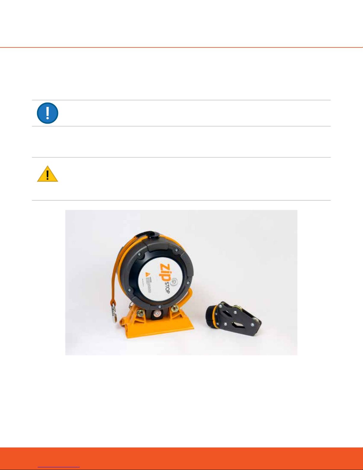
Brake Assembly Kit
www.headrushtech.com | +1-720-565-6885
Page 16

Do not use the zipSTOP after date shown here
3. Check the Certification Label on the zipSTOP Brake Unit for the ‘Next Recertification Required’ date. If
the date shown has passed or the label is missing or illegible then the zipSTOP Brake Unit must not be
put into service.
4. Register online at www.thezipshop.com/registration or fill out the Product Registration Card included
with the zipSTOP Brake Assembly Kit, and return it to your zipSTOP distributor.
5. The EAD Confirmation form and the Warranty Registration form (see Sections “Emergency Arrest Device (EAD) Confirmation” and “Warranty Registration Form” respectively) are required to be detached,
filled out, and mailed to:
Head Rush Technologies
1835 38th Street , STE C
Boulder, CO 80301
PRODUCT REGISTRATION MUST BE COMPLETED
The Product Registration must be completed, either by registering online or by filling out and returning the
Product Registration Card. This is critical for receiving product notifications and up-to-date information for
the proper use of the zipSTOP Brake assembly.
6. Read this entire Installation, Operation and Maintenance Manual supplied with the zipSTOP, and familiarize yourself with all aspects of installation, operation, care and maintenance.
7.3 Long Term Storage
If the zipSTOP Brake Unit is to be placed into storage or left unused for longer than two weeks, ensure the unit
is clean and dry and protected from the environment. Ensure the Braking Line is fully retracted into the unit.
Always store in a clean and dry environment, preferably in the original packaging
DO NOT STORE BRAKE UNIT IN A WET CONDITION
After exposure to water or damp conditions, thoroughly clean and dry the zipSTOP prior to storage. Ensure
that the zipSTOP Brake Unit is not left with a wet Braking Line retracted inside the casing as this may result
in corrosion of the unit and deterioration of the Braking Line. In a clean and dry environment, remove the
side covers and fully extend the wet Braking Line and allow to completely dry prior to storing the Brake Unit.
Ensure that debris does not enter the unit and reattach the side covers prior to storing or using the unit.
www.headrushtech.com | +1-720-565-6885
17
Page 17

When returning the zipSTOP Brake assembly to operation after an extended period of inactivity, always carry out a
ZIPSTOP
ZIP LINE
BRAKE
Installation, Operation & Maintenance Manual
Models: ZS125-08 / ZSIR150-20A
NOTE TO INSTALLERS
Always Read Instructions Before Use
Leave this manual attached to the zipSTOP Brake unit. The Installation, Operation
and Maintenance manual contains information relating to the proper use of the
zipSTOP and includes all product registration and warranty information. This document may only be removed by the end user prior to operation. Ensure that this
manual is readily available to operators at all times.
Head Rush Technologies zipSTOP Zip Line Brake Installation, Operation & Maintenance Manual
P/N 01170006604
Head Rush Technologies products are covered by a number of patents, including
U.S. Patents 8,490,751; 8,851,235; 9,016,435; 8,851,235 and D654,412 & corresponding patents/applications in the USA and in other countries worldwide.
full inspection and operational check of all components in the assembly. Refer to Section “Operation of zipSTOP” for Inspection procedures.
7.4 Supplied Parts
The following parts will be included in each Brake Assembly Kit:
1 x zipSTOP Brake Unit
1 x zipSTOP Mounting Bracket, Rattle Stop, Mounting and Lynch Pins
1 x zipSTOP Brake Trolley
zipSTOP Installation, Operation and Maintenance Manual
7.5 General and Additional Parts Required
Additional lines and equipment will be required to successfully install a zipSTOP Brake assembly within individual zip line installations. All hardware, fasteners and accessories used in the installation of zipSTOP must meet
or exceed the required loads and specifications, and must be made of materials compatible with all-season
outdoor use.
Head Rush Technologies developed specific redirection pulleys and the Gorilla rope to maximize the performance of a zipSTOP Zip Line Brake. The redirection pulleys oered by Head Rush Technologies are light-
Brake Unit Brake Unit Mounting Bracket
Brake Trolley Installation, Operation, & Maintenance Manual
18
www.headrushtech.com | +1-720-565-6885
Page 18

weight, corrosion resistant, and engineered to be virtually resistant to snagging. Head Rush Technologies also
oers the Gorilla Rope, a 6mm rope specifically designed for used as a redirection line.
7.6 Redirection Pulleys
The following parts are not supplied as part of the zipSTOP kit and may be purchased separately from your
zipSTOP distributor.
The Type I Pulley is fitted to the Secondary Anchor Point, and provides both support and a means of redirection for the Redirection Line. The Type I Pulley is required for both 1:1 and 2:1 Redirection Ratio setups.
A Type II Pulley is fitted between the zipSTOP Brake Unit and the Type I Pulley as required to provide support
and redirection for the Redirection Line and connections to the Braking Line. The Type II Pulley is only required on the 2:1 Redirection Ratio set-ups.
Example of Type I Redirection Pulley Example of Type II Redirection Pulley
7.7 Traveler Assembly
Sling
Oval Quicklink
zipSTOP Brake Line
The Traveler Assembly is a recommended support for a 2:1 ratio configuration. It is used to support the weight
of the Redirection Line and associated hardware in order to ensure that the Redirection Line does not contact
any surface other than the pulley sheaves. A sling of proper length should be used to ensure that the Braking
Line feeds straight out of the device, without twist, and centered within the Nozzle. A swivel is recommended
to ensure that the Braking Line remains free of twists.
Pulleys
Triangular Quicklink
Swivel
www.headrushtech.com | +1-720-565-6885
19
Page 19

7.8 Minimum Hardware Requirements
All required hardware is to be purchased separately. The following are minimum requirements for all hardware
used for zipSTOP installation:
DESCRIPTION SIZE QTY NOTES
Grade 4.6 (M12)
ZIPSTOP BRAKE UNIT MOUNTING
BOLTS, WASHERS & LOCKNUTS
M12 or 1/2”
3
ASTM A307 Grade A or B (1/2”)
Length to suit installation
Suitable for all-season outdoor use
TYPE I PULLEY MOUNTING
HARDWARE
CARABINERS, SNAPS, RINGS,
THIMBLES, CLEVISES
To suit To suit Suitable for all-season outdoor use
Minimum load rating 15 kN
To suit
Suitable for all-season outdoor use
7.9 Redirection Line
The Redirection Line is required to connect the zipSTOP Brake Unit to the Brake Trolley and will transfer the
braking force from the Brake Unit. The Redirection Line passes through the redirection pulleys and must meet
minimum specification. The following list provides several Redirection line options.
Head Rush Technologies developed the Gorilla Rope specifically for use as a redirection line with the zipSTOP
Zip Line Brake It features a high strength-to-weight ratio, is designed to be highly resistant to abrasion, UV
resistant, and water repellent. The 6mm Gorilla Rope maximizes performance because it is lighter, smaller in
diameter, minimizes resistance, and maximizes reliable reset.
Spectra - Spectra/Dyneema is one of the recommended materials because it has sucient strength while
minimizing size and diameter. Spectra/Dyneema is known for high strength and superior abrasion, water, and
UV resistance. The spectra line should be jacketed with an abrasion-resistant, temperature-tolerant material
to avoid possible degradation of the line due to friction. Gorilla Rope, a Head Rush Technologies product, is
designed specifically to provide high strength, a long life span, and minimal stretch for applications where a
small diameter rope is necessary. It is made for maximum durability and high performance in any application.
It is perfect for use as a reduction line with the zipSTOP Zip Line Brake but can also be used for many other
industrial or recreational applications where these qualities are critical.
Technora® - Technora, while the strongest of the synthetic fibers, is particularly sensitive to UV wear. Only
Technora core lines with UV protective jackets should be used. Technora lines are also slightly stier which
can increase retraction drag when used as a Redirection Line. The drag is usually oset by the fact that a
smaller diameter Technora line can be employed compared to another material.
Nylon and Other materials - Nylon or other materials can be used provided they meet the minimum requirements for strength, UV, and wear resistance. However, these lines may necessitate much larger diameter ropes
to attain the necessary strength which can have an adverse eect on Redirection Line performance.
20
Typical Technora Termination
www.headrushtech.com | +1-720-565-6885
Page 20

7.9.1 REDIRECTION LINE SPECIFICATIONS: ZS12508/ZSIR15020A
MAXIMUM DIAMETER 10.0 mm/0.394 in (6mm/0.236 in recommended)
MINIMUM STRENGTH 13 kN, Stretch <3% at 13 kN
STRETCH <4% at 15 kN
WEAR RESISTANCE High abrasion resistance and UV resistance
WATER RESISTANCE Dry, non-absorptive
TYPE Kernmantle or single braid construction
TYPICAL Redirection LINE EXAMPLE
ZS125-08
TYPICAL Redirection LINE EXAMPLE
ZS150-20A
ALWAYS USE THE SPECIFIED REDIRECTION LINE
Failure to utilize a Redirection Line of specified strength and quality can compromise zipSTOP brake operation, resulting in equipment damage, serious injury or death.
REDIRECTION LINE WILL BE SUBJECT TO WEAR AND ABRASION
Any Redirection Line selected for use will wear and must be replaced from time to time. Lines must be carefully inspected prior to use each day, and failure to do so may result in serious injury or death.
When selecting a Redirection line, the following considerations apply:
The line must meet the specifications described above.
A lighter, smaller diameter line is preferred, to minimize resistance and weight, and maximize reliable
reset.
A waterproof line is required. Water absorption can add significant weight, allowing the line to sag
which increases the likelihood of incomplete reset for Brake Unit and Brake Trolley.
www.headrushtech.com | +1-720-565-6885
21
Page 21

8. zipSTOP BRAKE ASSEMBLY CONFIGURATION
8.1 General
The zipSTOP Brake assembly is designed to be utilized as part of a complete zip line braking system, and can
be used for a wide range of zip line installations. The zipSTOP Brake assembly is suitable for use in both existing and new zip line installations.
Setup information contained within this manual relates only to the zipSTOP Brake assembly – The design,
installation and set-up of other components comprising the complete braking system are the responsibility of
the installer and/or operator.
COMPATIBILITY TESTING IS THE RESPONSIBILITY OF THE INSTALLER OR OPERATOR
The zipSTOP Brake is designed to work with most pulleys and zip lines but may not work with all. Compatibility is to be determined by the installer or operator based on experience and unmanned testing.
ALWAYS CARRY OUT UNMANNED TESTING TO DETERMINE ACTUAL BRAKING DISTANCE
The information contained in this manual is intended for guidance only. Calculated braking distances for
the zipSTOP Brake assembly are estimates only and may dier from actual braking distances achieved on
individual zip lines.
As there are infinite possibilities regarding participant weights and arrival speeds, line slopes and environmental
conditions, a safe and functional installation can only be achieved after careful consideration and unmanned
testing of all factors in advance of the zipSTOP installation.
The zipSTOP Brake is required to use both primary and emergency arrest devices functioning together to
arrest the motion of passengers. The EAD must engage with no input from the passenger upon failure of the
primary arrest device, and all required Confirmation and Warranty registration forms must be filled out and
returned; failure to do so may void your warranty (see Sections “Emergency Arrest Device (EAD) Confirmation”
and “Warranty Registration Form” respectively).
Pictures in this manual are for reference purposes in terms of geometry and proposed redirection setup
configuration only. Mandated EAD may or may not be shown.
8.2 Setup Variables, ZS125-08/ZSIR150-20A
A number of variables will influence the final braking distance and level of rider comfort, these include:
Rider arrival speed
Rider weight
Redirection Line Ratio (Only a 1:1 Applies with the ZSIR150-20A)
Zip line slope in the landing area
System friction
Environmental conditions (wind, rain, temperature)
Rider trolley used
22
www.headrushtech.com | +1-720-565-6885
Page 22

8.3 Rider Arrival Speed
Rider arrival speed is unique to each zip line installation and is a factor of line slope, zip line length, rider
weight, rider descent position, wind and friction. It is necessary to know the acceptable minimum and maximum rider velocities prior to configuring the zipSTOP.
8.4 Rider Weight
Suitable rider weight ranges will need to be determined by individual zip line operators. The zipSTOP Brake
unit will accommodate riders between 15 and 150 kg (33 and 330 lbs). It is necessary to know the acceptable
rider weight range before configuring the zipSTOP.
8.5 Redirection Line Ratio
The Redirection Ratio is the most influential factor in the braking characteristics of the zipSTOP. The Redirection Ratio is the ratio between the Brake Trolley travel and the zipSTOP Braking Line extension.
The Redirection Ratio is achieved by passing the Redirection Line around a series of pulleys. This alters the
ratio of Brake Trolley travel to Braking Line extension, allowing the installer to tailor the braking distances and
deceleration rates, accommodating a wide range of arrival speeds and rider weights.
ZSIR15020A THIS PRODUCT CAN ONLY BE USED WITH 1:1 REDIRECTION SETUPS
The zipSTOP IR (ZSIR150-20A) is NOT compatible with external redirection setups in any way. Installing
a redirection setup with the zipSTOP IR can create a very dangerous set of braking conditions that could
result in abnormally abrupt late braking.
Various Redirection Ratios are possible:
1:1 Ratio
MUST be used for model ZSIR150-20A
Can be used for model ZS125-08
2:1 Ratio
Can be used for model ZS125-08 only
CANNOT be used for model ZSIR150-20A
3:1 and higher ratios – contact your zipSTOP Distributor, model ZS125-08 only
The recommended configuration orients all elements (zipSTOP Brake Unit, Redirection Pulleys, Brake Trolley)
in the vertical plane.
When higher Redirection Ratios (3:1 and higher) are employed (for model ZS125-08 only), retraction force is
reduced and a manual reset of the Brake Trolley will be necessary.
ALWAYS USE THE SPECIFIED REDIRECTION LINE
Failure to utilize a Redirection Line of specified strength and quality can compromise zipSTOP brake operation, resulting in equipment damage, serious injury or death.
www.headrushtech.com | +1-720-565-6885
23
Page 23

REDIRECTION LINE WILL BE SUBJECT TO WEAR AND ABRASION
Any Redirection Line selected for use will wear and must be replaced from time to time. Lines must be carefully inspected prior to use each day, and failure to do so may result in serious injury or death.
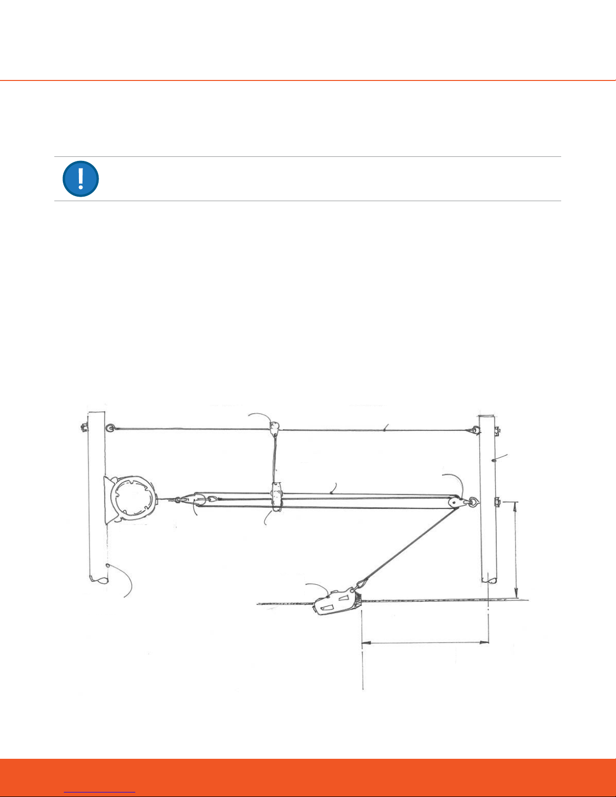
8.5.1 1:1 RATIO
Attach zipSTOP braking line to redirection
line with a quicklink and recommended
swivel, support pulley and sling
Attach redirection pulley
to overhead line
Overhead Line
Zip Line
Brake Trolley
The 1:1 Redirection Ratio directly connects the zipSTOP Brake Unit to the zipSTOP Brake Trolley via a single
Type I Redirection Pulley. For every unit of Brake Trolley travel, the Braking Line extends an equal distance.
Characteristics of the 1:1 ratio are:
Suitable for low speeds
Strongest braking force
Short braking distances
Higher rate of rider deceleration
Maximum rider approach speed of 36 km/h (22 mph) – model ZS125-08
Maximum rider approach speed of 60 km/h (37 mph) – model ZSIR150-20A
In the case of the model ZS125-08: A 1:1 Redirection Ratio is used for zip line installations where low arrival
speeds are common. Although suitable for speeds up to 36 km/h (22 mph), typically a 1:1 ratio would be employed when approach speeds are less than 20 km/h (12 mph).
24
*EAD not shown but it is mandated*
Overhead Cable – 1:1 Redirection Ratio
www.headrushtech.com | +1-720-565-6885
Page 24

8.5.2 2:1 RATIO
redirection line with a quicklink and
recommended swivel, support pulley
Attach zipSTOP braking line to
and sling
Attach redirection pulley
to overhead line
Overhead Line
Zip Line
Brake Trolley
*EAD not shown but it is mandated*
Overhead Cable – 2:1 Redirection Ratio
The 2:1 Redirection Ratio connects the zipSTOP Brake Unit to the zipSTOP Brake Trolley via both Type I and Type
II pulleys. With a 2:1 ratio the Brake Trolley travels twice the distance that the zipSTOP Braking Line extends.
Characteristics of the 2:1 ratio are:
Suitable for medium to high speeds
Optimal combination of stopping distance, braking force and reliability in reset
Optimum rider comfort
Longer braking distances than a 1:1 setup
Overhead support line (redirection point) recommended
Maximum approach speed of 60 km/h (36 mph)
A 2:1 Ratio is used on zip line installations where medium to high approach speeds are common but a soft
stop for the rider is desired. Although suitable for approach speeds up to 60 km/h (36 mph), typically a 2:1
ratio is employed when approach speeds are less than 40 km/h (24 mph).
A 2:1 Ratio is specifically PROHIBITED in any installation of the ZSIR150-20A. Utilizing an external redirection
will lead to potentially dangerous and harmful braking dynamics.
ZSIR15020A THIS PRODUCT CAN ONLY BE USED WITH 1:1 REDIRECTION SETUPS
The zipSTOP IR (ZSIR150-20A) is NOT compatible with external redirection setups in any way. Installing
a redirection setup with the zipSTOP IR can create a very dangerous set of braking conditions that could
result in abnormally abrupt late braking.
www.headrushtech.com | +1-720-565-6885
25
Page 25
8.6 Possible Configurations (Informative Only)
8.6.1 3:1 RATIO
3:1 installation formats are a unique situation and the following information should be used to develop an
appropriate site plan.
The 3:1 ratio connects the zipSTOP unit to the braking trolley via redirection pulleys and supplementary line.
With a 3:1 ratio the braking trolley travels three meters for every meter of zipSTOP line. This will result in a longer stopping distance for the rider.
Characteristics of 3:1 ratio setup are:
Max. Approach Speed = 72 km/h.
Suitable for high arrival speed.
Softer stopping force from higher speeds
Longer stopping distances
More complex set-up.
A 3:1 ratio is commonly used on zip lines with high arrival speeds and when a longer braking distance is available. The 3:1 ratio is suitable for approach speeds up to 72 km/h (45 mph) allowing a softer stop after thrilling
high speed runs.
Primary Anchor
zipSTOP
Support Wheel
Secondary
Pulley
Redirection Line
Cable Tidy
zipSTOP
Brake Trolley
Support Line
Start of
Braking Zone
Double
Pulley
Block
Locate Secondary
Anchor Upstream
of Braking Zone
Secondary
Anchor
Line
Locate Pulley
Block Above Zip
26
www.headrushtech.com | +1-720-565-6885
Page 26
8.6.2 OTHER CONFIGURATIONS
The zipSTOP Brake assembly may be used with other zip line configurations and higher rider velocities. Configurations shown are based on a single line zip line. Dual zip lines and side-by-side configurations may also
be accommodated. Please contact your zipSTOP Distributor for information on alternate set-ups.
When higher Redirection Ratios (3:1 and higher) are employed (for model ZS125-08 only), retraction force is
reduced and a manual reset of the Brake Trolley will be necessary.
Pictures in this manual are for reference purposes in terms of geometry and proposed redirection setup
configuration only. Mandated EAD may or may not be shown.
Some examples of alternative configurations are shown below:
Beam Mounted Pulley - 2:1 Redirection Ratio
8.7 Zip Line Slope
Three zip line configurations at the end of the line are possible: flat line, positive line slope and a negative line
slope. The slope of the line will influence the braking distances as well as allowing the rider to roll slowly up or
down the line once decelerated.
www.headrushtech.com | +1-720-565-6885
Oset Redirection Pulley – 1:1 Redirection Ratio
NOTE: Oset redirection pulleys should only be used with highly
tensioned zip lines. Slack zip lines may cause binding and excessive
wear on the brake trolley.
27
Page 27

8.7.1 POSITIVE SLOPE LINE
This is the ideal configuration when designing a zip line incorporating the zipSTOP Zip Line Brake. The positive
line slope configuration equalizes the braking distance between heavy and light riders, therefore minimizing
the length needed for the arrival platform.
zipSTOP
Primary Mount
Secondary Mount
Landing Area
Brake Trolley
Minimum Braking Distance
Roll Forward
Maximum Braking Distance
Arrest Zone
Reset Position
Positive Line Slope
On positive line installations riders will decelerate within the Arrest Zone but may continue to slowly roll forward on completion of braking.
It is recommended that the platform is positioned to allow all riders to roll forward on to the platform for a
safe dismount.
8.8 Flat Line
On a flat line participants will decelerate within the Arrest Zone at the completion of braking but typically don’t
roll forward or backward.
It is recommended that the platform is positioned to allow all riders to safely dismount.
zipSTOP
Primary Mount
Secondary Mount
Landing Area
28
Brake Trolley
Minimum Braking Distance
Maximum Braking Distance
Arrest Zone
Reset
Position
Flat Line
www.headrushtech.com | +1-720-565-6885
Page 28

8.9 Negative Slope Line
On negative line installations riders will decelerate within the rider Arrest Zone and may roll backwards at the
completion of braking.
It is recommended that the platform is positioned to allow all riders to safely dismount.
zipSTOP
Primary Mount
Landing Area
Roll Back
Maximum Braking Distance
Minimum Braking Distance
Arrest Zone
Secondary Mount
Brake Trolley
Negative Line Slope
Reset
Position
8.10 Calculating zipSTOP Braking Distances
To calculate braking distances for the zipSTOP Brake assembly, follow the steps in the ‘Configuration Worksheet’ using the information contained in the ‘Braking Distance Charts’. Refer to Section “Appendix A: EAD
Warranty/Registration Form”.
ALWAYS CARRY OUT UNMANNED TESTING TO DETERMINE ACTUAL BRAKING DISTANCE
The information contained in this manual is intended for guidance only. Calculated braking distances for the zipSTOP Brake assembly are estimates only and may dier from actual braking distances achieved on individual
zip lines.
Exceeding maximum recommended line speed can cause injury to participants and damage equipment.
Before starting the zipSTOP configuration you will need to determine the rider weight range, rider arrival speed
range and preferred Redirection Ratio for the zipSTOP installation.
Information required for calculating zipSTOP braking distances:
Rider weight range
Arrival speed range
zipSTOP Redirection Line ratio
A number of other variables will aect the final performance of zipSTOP and must be taken into consideration
when designing the complete zip line braking system. These include, but are not limited to:
Line slope
EAD design
Friction
Weather Conditions (e.g. wind, rain, humidity, temperature)
Environmental factors
www.headrushtech.com | +1-720-565-6885
29
Page 29

8.10.1 DEFINITION OF TERMS
The following terms are used when configuring and installing the zipSTOP Brake assembly:
Pivot Length
Primary Mount
zipSTOP
Brake Line Extension
Buer Zone
Roll Forward
Minimum Braking Distance (BD min)
Maximum Braking Distance (BD max)
Roll Back
Landing Area
Secondary Mount
Pivot Height
Brake Trolley
Rider Arrival Speed
Maximum Arrival Speed = ASmax
Minimum Arrival Speed = ASmin
Reset
Position
Redirection LINE RATIO RR
Ratio of Brake Trolley travel to zipSTOP line extension
(LEX)
RIDER ARRIVAL SPEED
ASMAX = MAXIMUM RIDER ARRIVAL SPEED ASmax Speed at which rider enters the Arrest Zone.
ASMIN = MINIMUM RIDER ARRIVAL SPEED ASmin Determined by:
Slope of zip line
Rider size and weight
Wind speed and direction
Rider trolley rolling resistance
BRAKING DISTANCE Distance required to decelerate a rider.
BDMAX = MAXIMUM BRAKING DISTANCE
BDMIN = MINIMUM BRAKING DISTANCE
NOTE: Configurations that result in Braking distances that fall below the ‘BDmin’ line shown on the
chart are not recommended. These short braking distances may be uncomfortable for the rider and
may result in severe swinging up of rider when decelerating.
30
BDmax
BDmin
Braking distance is determined by:
Arrival speed
Rider weight
Redirection Ratio
Slope of zip line at landing area
www.headrushtech.com | +1-720-565-6885
Page 30

RIDER BRAKING RANGE BR
NOTE: Landing Area will vary depending on rider arrival speed, stopping distances and line slope.
Dierence between maximum and minimum braking distances.
RESET POSITION
BUFFER ZONE
PIVOT HEIGHT
LINE EXTENSION
RP
BZ
PH
LEX
The reset position defines the start of the Arrest
Zone and is the location on the zip line the Brake
Trolley will return to once the rider is removed.
Distance from the end of the Arrest Zone (AZ) to any
object that may impact the rider in the event the
rider overshoots the landing area.
The buer zone must include the maximum distance required for the EAD to activate and arrest a
rider.
Straight line distance between Brake Trolley and the
Type 1 Pulley. Changing pivot height will influence
the stopping distance.
Distance that zipSTOP internal Braking Line extends
from the zipSTOP Brake unit.
Min. LEX = 0.40 m (15.5”)
Max. LEX = 12.0 m (39’4”)
RIDER WEIGHT RW The weight of the rider (min and max
8.11 zipSTOP Braking Distance Charts
Charts for calculating braking distances are located at the back of this manual. These charts are to be used in
conjunction with the zipSTOP configuration worksheet to optimize the zipSTOP installation. Ensure that you
are using the correct chart for your zipSTOP model.
ALWAYS CARRY OUT UNMANNED TESTING TO DETERMINE ACTUAL BRAKING DISTANCE
The information contained in this manual is intended for guidance only. Calculated braking distances for the zipSTOP Brake assembly are estimates only and may dier from actual braking distances achieved on individual zip
lines. Exceeding maximum recommended line speed can cause injury to participants and damage equipment.
8.12 Configuration Notes
1. BDMIN LINE: BDmin line indicates the rate of deceleration that may be considered uncomfortable
and result in severe rider swing up when stopping. It is not recommended to operate the zipSTOP with
combinations of rider weights and arrival speeds that fall below the BDmin line. Operating below the
BDmin line runs the risk of rider swinging up and contacting the zip cable.
www.headrushtech.com | +1-720-565-6885
31
Page 31

2. LINE EXTENSION (LEX) – Line extension is the distance the Braking Line extends out of the zipSTOP
brake Unit. If LEX is greater than 12.0m then reduce maximum permissible approach speed (ASmax),
permissible rider weight (RWmax) or increase Redirection Ratio (RR). Exceeding 12m runs the risk of an
abrupt stop when the webbing reaches its termination as well as damage to the zipSTOP, webbing and
other equipment.
3. BUFFER ZONE (BZ) – Buer zone is the area after the Arrest Zone in which riders are safe from impacting the terminal end or any other object in the event they overshoot the landing zone. The buer zone
must include the maximum distance required for the EAD to arrest a wayward rider.
32
www.headrushtech.com | +1-720-565-6885
Page 32

8.13 zipSTOP Configuration Worksheet
Use this worksheet in conjunction with the braking distance charts at the back of this manual. Worksheet
must be completed in metric. Read the zipSTOP Brake assembly configuration notes and definitions before
completing the worksheet. Distances calculated by this worksheet are based on a flat line with no outside
influences such as wind, friction etc. Actual braking distances can vary from these values. Always determine
actual braking distances by completing unmanned test runs on final zip line installation prior to putting the
installation into operation.
1 Select Redirection Ratio and go to braking distance chart for selected Redirection Ratio.
If Redirection Ratio = 1:1, enter 1
If Redirection Ratio = 2:1, enter 2 (model ZS125-08 only)
2 Enter maximum expected rider arrival speed (ASmax) ASmax =
Enter minimum expected rider arrival speed (ASmin) ASmin =
3 Enter maximum anticipated rider weight RWmax =
4 Enter minimum anticipated rider weight RWmin =
5 Determine pivot height
Minimum pivot height = 1.0 m (40”)
6 Enter buer zone length BZ
7 Go to braking distance chart for selected Redirection Ratio and Model Number. Reference the metric
charts available on pages 60 & 62.
8 From relevant chart determine the braking distance for maximum anticipated rider
weight (RWmax) and speed
9 Add pivot height to give maximum braking distance
BDmax = BD1 + PH
RR =
PH
BD1 =
BDmax =
10 Check maximum braking distance + buer zone does not exceed maximum zipSTOP
Braking Line extension.
Line Extension (LEX) = (BDmax + BZ) / RR
LEX must be less than or equal to 12.
11 From relevant chart determine braking distance for minimum anticipated rider weight BD2 =
12 Add pivot height to give minimum braking distance.
BDmin = BD2 + PH
13 Check stopping distance is not below the ‘BDmin’ line. Distances below this line will
result in a severe deceleration for the rider
14 Calculate braking range:
BR = BDmax – Bdmin
15 Calculate Reset Point (Arrest Zone Start Point):
RP = BDmax + BZ
www.headrushtech.com | +1-720-565-6885
LEX =
(see Note 1)
BDmin =
Above BDmin line?
BR =
RP =
Y / N
33
Page 33

9. zipSTOP BRAKE ASSEMBLY INSTALLATION
9.1 General
Simply put, the zipSTOP Brake is designed to be mounted to a primary anchor point to slow the decent of
riders on a zip line. The primary anchor point is exactly what it sounds like; it is the main attachment point for
the brake. The secondary anchor point is the support point for the redirection lines and pulleys.
The zipSTOP Brake Unit is installed at the end of the zip line, usually on or adjacent to the terminal end. A
Secondary Anchor Point is normally required upstream of the landing area to provide support for the Redirection Line pulleys AND forces associated with braking. Alternately a full-length secondary cable of sucient
capacity can be installed to provide support for the Redirection Line and associated pulleys.
Pictures in this manual are for reference purposes in terms of geometry and proposed redirection setup
configuration only. Mandated EAD may or may not be shown.
9.2 Safety Precautions
ALWAYS INSTALL AN EMERGENCY ARREST DEVICE EAD
An independent arrest device is required to safely stop riders in the event of operator error or third party
equipment failure.
PROPER DESIGN AND TESTING OF THE COMPLETE BRAKING SYSTEM IS ALWAYS REQUIRED
The complete brake system for zip Lines consists of all brakes employed, including primary brake and EAD.
All braking installations that include the zipSTOP as a component of the braking system must be designed,
tested and operated according to this Installation, Operation and Maintenance Manual and proper industry
and engineering practices. Failure to do so may result in serious injury or death to participants.
Exceeding maximum recommended line speed can cause injury to participants and damage equipment.
FAILURE TO CORRECTLY INSTALL OR MAINTAIN A ZIPSTOP BRAKE ASSEMBLY MAY RESULT IN
SERIOUS INJURY OR DEATH TO PARTICIPANTS.
ALWAYS CARRY OUT UNMANNED TESTING TO DETERMINE ACTUAL BRAKING DISTANCE
The information contained in this manual is intended for guidance only. Calculated braking distances for
the zipSTOP Brake assembly are estimates only and may dier from actual braking distances achieved on
individual zip lines.
AVOID CONTACT BETWEEN RIDER AND RIDER TROLLEY AND/OR BRAKE TROLLEY
Serious injury may result if rider contacts the rider trolley or Brake Trolley during the braking phase. Always
design zipSTOP Brake assembly installation to ensure rider cannot make contact with, or have any part of
their body caught between, the rider trolley and Brake Trolley.
34
www.headrushtech.com | +1-720-565-6885
Page 34

ENSURE ALL CABLES, ATTACHMENT LINES AND PULLEYS ARE CORRECTLY ATTACHED AND
MAINTAINED TO PREVENT TANGLING, SNAGGING, BINDING AND ABRASION.
Ensure that the Redirection Line is routed cleanly and in line through the pulley system, to prevent contact
with any surface other than the pulley sheaves.
ALL STRUCTURES, SUPPORTS AND ANCHORS MUST BE EVALUATED AND DESIGNED AC
CORDING TO PROPER INDUSTRY AND ENGINEERING PRACTICES. QUESTIONS ABOUT
STRUCTURES, SUPPORTS AND ANCHORS SHOULD BE REFERRED TO YOUR ZIP LINE’S ENGI
NEER.
The act of decelerating a rider at the termination of a zip line can generate extreme loads.
9.3 Primary Anchor Point
The Primary Anchor Point provides support for the zipSTOP Brake Unit. The anchor point and associated
fittings must be of sucient strength and form to provide a secure mount and to support all applied loads
sustained during zip line operation.
Loads specified are for the zipSTOP Brake assembly installation only and do not allow for any additional equipment or other loadings applied to the primary mount or additional units attached to the same line.
The zipSTOP Brake Unit is attached to the Primary Anchor Point using three M12 or ½” fixing bolts.
Loads at Primary Anchor Point
In-line with Braking Line 6.0 kN
Right angles to Braking Line Negligible
The loads specified are applied loads for the zipSTOP Brake Unit only. These loads DO
NOT allow for additional loads applied by other equipment or structures. Ensure sucient
factor of safety is applied in the structural design of all zip line installations.
9.4 Secondary Anchor Point
The Secondary Anchor Point provides support for redirection pulleys and hardware used in the Redirection
Line setup. The design of the Secondary Anchor Point must be sucient to withstand all applied loads experienced during zip line operation.
Loads specified are for zipSTOP Brake assembly installation only and do not allow for any additional equipment or other loadings applied to the secondary mount including redirection lines for additional units.
Loads at Secondary Anchor Point
Inline with Redirection Line 11.0 kN
Right angles to Redirection Line 3.5 kN
The loads specified are applied loads for the Redirection Line and Redirection Pulley only.
These loads DO NOT allow for additional loads applied by other equipment or structures.
Ensure sucient factor of safety is applied in the structural design of all zip line installations.
www.headrushtech.com | +1-720-565-6885
35
Page 35

9.4.1 POSITION OF THE SECONDARY ANCHOR POINT
The Secondary Anchor Point is located in line with the start of the Arrest Zone (Brake Trolley Reset Point). It
provides the location for the attachment of the Type I Pulley above the zip line and also attachment of any
secondary or support lines that may be required.
Ensure the Secondary Anchor Point and any supporting structure are at least one meter above the zip line and at
a sucient distance from the zip line to prevent contact with the rider, redirection line, and other equipment.
Always install pulleys so as to prevent any tangling, snagging or binding with other lines or objects. Ensure that
the Redirection Line is routed cleanly and in line through the pulley system to prevent contact with any surface
other than the pulley sheaves.
9.5 Redirection and Support Lines
All lines must be sewn, spliced, or properly terminated.
Only use an approved termination method for all rope connections. Using a Double Figure 8 knot to terminate a Redirection Line is not recommended by Head Rush Technologies for lines with Spectra or Dyneema
sheaths. Spectra and Dyneema have low coecients of friction which can result in knots becoming untied. A
Double Figure 8 knot also reduces line strength by 20-25% when tied properly and can reduce line strength by
more if tied incorrectly.
All Redirection Lines and support lines are to be manufactured to specified strength and are to be suitable for
all-season outdoor. When installing redirection and support lines, use route lines to ensure that:
All lines are installed in such a way as to prevent loose or sagging lines, tangling, snagging or binding with
other zip line components.
Lines are to be routed to eliminate abrasion and undue wear.
All lines are laid out so as not to present a tripping or injury hazard to zip line sta or riders.
36
Typical Figure-of Eight Knot
www.headrushtech.com | +1-720-565-6885
Page 36

9.6 Fitting zipSTOP Brake Unit
The zipSTOP Brake Unit may be mounted horizontally or vertically. The mounting bracket is designed for use
with a flat or curved surface. Curved surfaces must have a minimum 150 mm (6“) diameter.
ONLY INSTALL THE ZIPSTOP BRAKE UNIT ORIENTED DIRECTLY INLINE WITH THE TYPE 1 PULLEY
The Braking Line feeds straight out of the device, without twist, and centered within the Nozzle. Accelerated Braking Line wear may occur if the line bears onto the Nozzle edge.
DO NOT REUSE SELFLOCKING NUTS
Always use new nuts, as reuse of self-locking nuts may compromise connection integrity. This type of nut
is used on the Brake Trolleys.
Fit the zipSTOP Brake Unit as follows:
INSTALLATION NOTES
Always orient the zipSTOP Brake Unit directly in line with Type I Pulley.
Always use through bolts with large washers and self locking nuts.
It is recommended that double helix spring washers are located under mounting nuts to allow for movement in
primary mount point when used on a wooden structure or use split ring washer or comparable with a rigid structure
to reduce risk of loosening due to vibration
Always mount the zipSTOP Brake Unit a sucient distance from the zip line so that Redirection Lines and pulleys do
not interfere with rider.
Once installation is complete ensure the zipSTOP Braking Line is not twisted and feeds linearly through the Nozzle.
Install the rubber RattleStop bumper
Install the RattleStop pin
INSTALL THE RATTLESTOP
www.headrushtech.com | +1-720-565-6885
37
Page 37

Install the RattleStop washers to both sides
Install the RattleStop screws to both sides.
Tighten the screws on both sides
ATTACH MOUNTING BRACKET TO PRIMARY SUPPORT
Attach the supplied mounting bracket to the primary support with three (3) M12
or ½” hex head through bolts. The bolt holes are located 100mm (3.94in) apart on
center.
Check bolt head is correctly located in the zipSTOP Brake Unit mount.
Secure with flat washers, double helix spring washers and self-locking nuts.
Torque fasteners to maximum of 15 Nm (11 ft-lb). Do not over-torque fasteners.
38
www.headrushtech.com | +1-720-565-6885
Page 38

INSTALL ZIPSTOP TO MOUNTING BRACKET
Line up zipSTOP Brake Unit with the bottom mounting hole and insert the corresponding retaining pin and lynch pin.
Swing the zipSTOP Brake Unit up and apply a small amount of pressure against
the RattleStop until upper mounting holes align.
Fit the upper mounting pin and lynch pin.
Check both lynch pins are correctly located and secure.
In order to prevent tampering, insert a padlock or bolt in place of the lynch pin.
www.headrushtech.com | +1-720-565-6885
39
Page 39

9.7 Fitting the Brake Trolley
The Brake Trolley is installed on the zip line and is used to transfer the energy of the rider to the zipSTOP Braking
Unit.
ALWAYS USE THE CORRECT BRAKE TROLLEY SIZE FOR THE ZIP LINE
Failure to use the correct size may prematurely wear the trolley or zip line.
ENSURE THAT THE ZIPSTOP BRAKING LINE IS FULLY RETRACTED INTO THE ZIPSTOP DEVICE
AT BRAKE INITIATION
If any Braking Line is extended, braking force will be increased, resulting in participant injury or damage to
the zipSTOP Brake Unit. Ensure brake trolley and zipSTOP are properly reset before every run.
NOT RECOMMENDED FOR LOW TENSION LINES WITH OFFSET REDIRECTION PULLEY
Oset redirection pulleys should only be used with highly tensioned zip lines. Slack zip lines may cause
binding and excessive wear on the brake trolley.
To fit the Brake Trolley:
INSTALLATION NOTES
Check the correct size Brake Trolley for zip line is being used.
Some disassembly is required to fit the Brake Trolley to zip line.
The Brake Trolley is installed with the Bump Stop toward the direction of rider arrival.
Ensure the two lower pulley wheels are located below the line and the single upper wheel is above the line.
Check Brake Trolley is the correct size for the zip line. Trolley size is located on
the label.
Remove Redirection Line mounting point …>>
40
www.headrushtech.com | +1-720-565-6885
Page 40

>>…Upper Sheave…>>
>>…and top half of the Bump Stop from the Brake Trolley.
Place the Brake Trolley on the zip line with the Bump Stop facing the direction
of the approaching rider.
Refit the upper half of the Bump Stop. Torque to 6 Nm (4.5 lb-ft)
Refit the Redirection Line mounting point. Torque to 15 Nm (11 lb-ft).
www.headrushtech.com | +1-720-565-6885
41
Page 41

Refit the Upper Sheave to the Brake Trolley, ensuring that all spacers are correctly positioned. Secure the upper wheel with bolt, washer and self-locking
nut. Torque to 15 Nm (11 lb-ft).
Check all fasteners are properly torqued. Do not over tighten.
Check Brake Trolley rolls smoothly on zip line.
9.8 Fitting Type I Pulley
ZSIR15020A THIS PRODUCT CAN ONLY BE USED WITH 1:1 REDIRECTION SETUPS
The zipSTOP IR (ZSIR150-20A) is NOT compatible with external redirection setups in any way. Installing
a redirection setup with the zipSTOP IR can create a very dangerous set of braking conditions that could
result in abnormally abrupt late braking.
The Type I Pulley is fitted to the Secondary Anchor Point, and provides both support and a means of redirection for the Redirection Line. The Type I Pulley is required for both 1:1 and 2:1 Redirection Ratio setups. The
Type I Pulley may be fixed horizontally or vertically to a solid surface or be clamped to a cable. The Type I
Pulley incorporates dedicated line attachment points for dead-end loops.
Fit the Type I Pulley as follows:
INSTALLATION NOTES
Always position the Type I Pulley higher than the zip line. A minimum of 1.0 meter (39.37”) is required.
Ensure the position of the pulley will not allow contact or interference between the rider and any lines or equipment.
Ensure the redirection pulley meets the load requirements as defined in this manual
Ensure the Type I pulley assembly is mounted on a load bearing surface capable of withstanding all applicable load
bearing requirements.
Ensure that the Redirection Line is routed cleanly and in line through the pulley system, to prevent contact with any
surface other than the pulley sheaves. Fixed support pulley(s) can be used to ensure that Redirection Lines are kept
free and clear.
42
www.headrushtech.com | +1-720-565-6885
Page 42

9.9 Fitting Type II Pulley
The Type II Pulley is fitted between the zipSTOP Brake Unit and the Type I Pulley as required to provide support
and redirection for the Redirection Line and connections to the Braking Line. The Type II Pulley is only required on the 2:1 Redirection Ratio set-ups.
Fit the Type II Pulley so as to ensure the position of the pulley will not allow contact or interference between
the rider and any lines or equipment
It is recommended that an overhead support line and link be used with the Type II Pulley to reduce the risk of
line entanglement and assist proper travel of pulley assembly.
Attach zipSTOP braking line to
redirection line with a quicklink and
recommended swivel, support pulley
and sling
Attach redirection
pulley to
overhead line
Overhead Line
Zip Line
9.10 Fitting Redirection Line
ONLY USE APPROVED TERMINATION METHODS FOR ALL ROPE CONNECTIONS
www.headrushtech.com | +1-720-565-6885
Brake Trolley
Double Line – 2:1 Redirection Ratio Example
43
Page 43

ENSURE THAT THE REDIRECTION LINE IS ROUTED CLEANLY & IN LINE THROUGH THE PULLEY
SETUP
Contact between Redirection Line and any surface other than the pulley sheaves must be prevented in order
to eliminate abrasion and undue wear. The redirection line must remain free and clear of all obstacles, the
Arrest Zone and rider travel path.
THE INTEGRITY OF THE REDIRECTION LINE IS PARAMOUNT TO USER SAFETY
Failure of the redirection line will result in no activation of the primary brake and may result in serious injury
or death of the rider.
THE INTEGRITY OF THE REDIRECTION LINE IS PARAMOUNT TO USER SAFETY
Failure of the redirection line may result in serious injury or death of the rider.
ENSURE THAT THE ZIPSTOP BRAKING LINE IS FULLY RETRACTED INTO THE ZIPSTOP DEVICE
AT BRAKE INITIATION
If any Braking Line is extended, braking force will be increased, resulting in participant injury or damage to
the zipSTOP Brake Unit.
ENSURE THAT THE SPECIFIED REDIRECTION LINE MEETS THE SPECIFICATIONS DESCRIBED IN
THIS MANUAL
Use of poor quality Redirection Line may lead to zip line brake failure.
Attachment of the Redirection Line will dier depending on the Redirection Ratio utilized for each zipSTOP installation.
The length of the Redirection Line must be sucient to reach between terminations with a single, continuous line.
9.11.1 1:1 REDIRECTION RATIO
Ensure the Type I pulley is securely fitted to the Secondary Anchor Point and is located higher than the adjacent zip line, and in line with the start of the Arrest Zone.
Attach zipSTOP braking line to redirection
line with a quicklink and recommended
swivel, support pulley and sling
Overhead Line
Brake Trolley
*EAD not shown but it is mandated*
Single Line with 1:1 Ratio Shown
Attach redirection
pulley to
overhead line
Zip Line
44
www.headrushtech.com | +1-720-565-6885
Page 44

INSTALLATION NOTES
Check that the Redirection Line diameter is compatible with the redirection pulley size.
Check that the Redirection Line meets the specified strength, diameter, wear resistance and UV resis-
tance requirements.
Ensure that the Redirection Line is routed cleanly and in line through the pulley system, to prevent con-
tact with any surface other than the pulley sheaves. Fixed support pulley(s) can be used to ensure that
Redirection Lines are kept free and clear. The ZSIR150-20A MUST use a 1:1 redirection line ratio.
Position the Brake Trolley at the start of the Arrest Zone (Reset Position) and temporarily
secure it at that position.
Connect the Redirection Line directly to the Brake Trolley using a proper termination
method and an optional load rated link.
If an optional load rated link is utilized, ensure the gate on the link is screwed tight and
thread lock compound is applied to prevent it from loosening over time.
Ensure the Type I pulley is correctly positioned and secure.
Pass the Redirection Line through the Type I pulley ensuring it enters the pulley from
underneath and passes over and around the sheave in the direction of the zipSTOP Brake
Unit.
Ensure zipSTOP Brake Unit is in the fully retracted position.
NOTE: Braking Line extends approximately 400 mm (16”) from Nozzle in fully retracted
position.
DO NOT TIE REDIRECTION LINE DIRECTLY TO BRAKING LINE
A quicklink or comparable must be used.
Tension the Redirection Line and connect directly to the end loop of
the zipSTOP Braking Line using both a proper termination method and
suitable locking link.
Ensure the gate on the locking link is screwed tight and thread lock
compound is applied to prevent it from loosening over time.
www.headrushtech.com | +1-720-565-6885
45
Page 45

FOLLOWING THE INSTALLATION OF THE REDIRECTION LINE
Remove temporary restraint from the Brake Trolley.
Check the Redirection Line to ensure that the Brake Trolley is in the correct Reset Position when zip-
STOP Braking Line is fully retracted.
Ensure that the Redirection Line is routed cleanly and in line through the pulley system, to prevent con-
tact with any surface other than the pulley sheaves. Fixed support pulley(s) can be used to ensure that
Redirection Lines are kept free and clear.
Tie back any loose ends and check that all lines are free and untangled.
Push the Brake Trolley down the zip line and check that no binding or interference occurs between the
Redirection Line and any other part of the zipSTOP installation.
Check that the maximum travel that can be achieved by the Brake Trolley does not exceed the full Line
Extension of zipSTOP Braking Line.
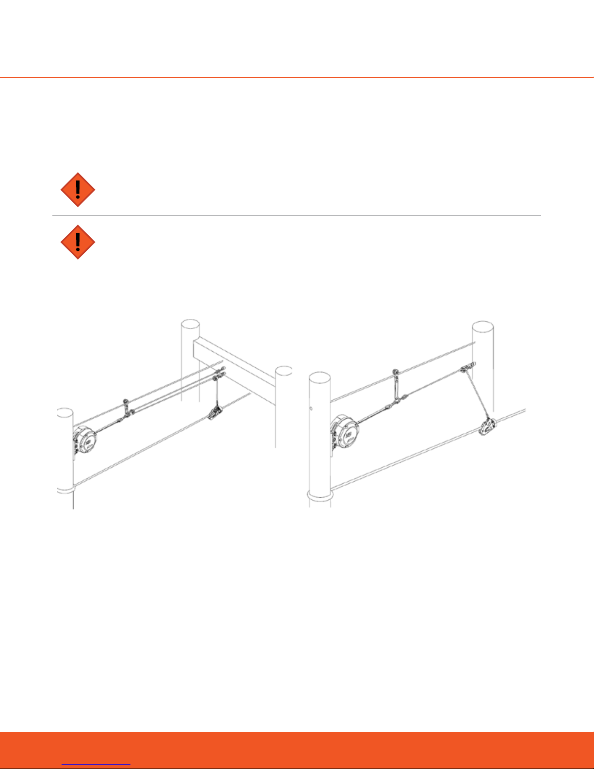
9.11.2 2:1 REDIRECTION RATIO
Attach zipSTOP braking line to
redirection line with a quicklink and
recommended swivel, support pulley
and sling
Attach redirection pulley
to overhead line
Overhead Line
Zip Line
Brake Trolley
*EAD not shown but it is mandated*
2:1 with Double Line
INSTALLATION NOTES
Check that the Redirection Line diameter is compatible with the redirection pulley size.
Check that the Redirection Line meets the specified strength, diameter, wear resistance, and UV resis-
tance standards.
When using a 2:1 ratio, it is recommended that a support cable be installed to provide support for the
Type II Pulley.
Ensure that the Redirection Line is routed cleanly and in line through the pulley system, to prevent con-
46
www.headrushtech.com | +1-720-565-6885
Page 46

tact with any surface other than the pulley sheaves. Fixed support pulley(s) can be used to ensure that
Redirection Lines are kept free and clear.
2:1 AND HIGHER RATIOS CAN ONLY BE USED WITH THE ZS12508
DO NOT use the ZSIR150-20A in 2:1 or higher configurations.
ENSURE THAT THE ZIPSTOP BRAKING LINE IS FULLY RETRACTED INTO THE ZIPSTOP DEVICE
AT BRAKE INITIATION
If any Braking Line is extended, braking force will be increased, resulting in participant injury or damage to
the zipSTOP Brake Unit. The warranty will be void.
ENSURE THAT THE SPECIFIED REDIRECTION LINE MEETS THE SPECIFICATIONS DESCRIBED IN
THIS MANUAL
Use of poor quality Redirection Line may lead to zip line brake failure.
Position the Brake Trolley at the start of the Arrest Zone (Reset Position),
and temporarily secure it at that position.
Connect the Redirection Line directly to the Brake Trolley using a proper termination method and an optional load rated link.
If a load rated link is utilized, ensure the gate on the link is screwed tight
and thread lock compound is applied to prevent it from loosening over
time.
Ensure the Type I pulley is correctly positioned and secure.
Pass the Redirection Line through the Type I pulley ensuring it passes
through the sheave in the direction of the zipSTOP Brake Unit.
Ensure zipSTOP Brake Unit is in the fully retracted position with the
Type II pulley correctly positioned and secure on the zipSTOP Braking
Line.
NOTE: Braking Line extends approximately 400 mm (16”) from Nozzle
in fully retracted position.
www.headrushtech.com | +1-720-565-6885
47
Page 47

Run the Redirection Line towards the zipSTOP Brake Unit, pass the Redirection Line around the Type II Pulley ensuring it passes through the
sheave in the direction of the Secondary Anchor Point.
Tension the Redirection Line and connect to the dedicated mounting
point on the Secondary Anchor Point using an approved proper termination method.
FOLLOWING INSTALLATION OF Redirection LINE
Remove temporary restraint from Brake Trolley
Check the Redirection Line to ensure that the Brake Trolley is in the correct Reset Position when zip-
STOP Braking Line is fully retracted.
Ensure that the Redirection Line is routed cleanly and in line through the pulley system, to prevent con-
tact with any surface other than the pulley sheaves. Fixed support pulley(s) can be used to ensure that
Redirection Lines are kept free and clear.
Tie back any loose ends and check that all lines are free and untangled.
Push the Brake Trolley down the zip line and check that no binding or interference occurs between the
Redirection Line and any other part of the zipSTOP installation.
Check that the maximum travel that can be achieved by the Brake Trolley does not exceed the full Line
Extension of zipSTOP Braking Line.
48
www.headrushtech.com | +1-720-565-6885
Page 48

10. OPERATION OF zipSTOP
10.1 Safety Precautions
ALWAYS CORRECTLY INSTALL, MAINTAIN AND OPERATE THE ZIPSTOP BRAKE ASSEMBLY
Failure to do so may result in serious injury or death to participants.
ALWAYS OPERATE A ZIPSTOP BRAKE ASSEMBLY WITH AN EMERGENCY ARREST DEVICE EAD
ACTIVE
Failure to do so may result in serious injury or death to participants
ALWAYS CARRY OUT UNMANNED TESTING TO DETERMINE ACTUAL BRAKING DISTANCE
The information contained in this manual is intended for guidance only. Calculated braking distances for
the zipSTOP Brake Assembly are estimates only and may dier from actual braking distances achieved on
individual zip lines.
ALWAYS OPERATE WITH RIDER FACING FORWARD UPON ARRIVAL INTO THE ARREST ZONE
Serious injury due to upswing may result if rider is not in the forward-facing position. Arrivals without
orientation control should be verified such that minimum and maximum rider weight patrons cannot come
into contact with the line, brake trolley, or other equipment during deceleration when arriving backwards
uncontrolled.
ALWAYS USE THE CORRECT ZIPSTOP BRAKE TROLLEY
Failure to use the correct trolley may compromise system operation and result in serious injury to rider.
AVOID CONTACT BETWEEN RIDER AND RIDER TROLLEY AND/OR BRAKE TROLLEY
Serious injury may result if rider is in contact with trolley when it impacts the Brake Trolley. Always design
the zipSTOP installation so rider cannot be in contact with, or have any part of their body caught between,
the rider trolley and Brake Trolley.
ENSURE ALL CABLES, ATTACHMENT LINES AND PULLEYS ARE CORRECTLY ATTACHED AND
MAINTAINED
Ensure that the Redirection Line is routed cleanly and in line through the pulley setup, to prevent contact
with any surface other than the pulley sheaves. Any tangling, snagging, binding and abrasion may compromise system operation and result in serious injury to rider.
AVOID MAXIMUM LINE EXTENSION OF BRAKING LINE
Repeated extension of braking line to maximum Line Extension (LEX as defined in this manual) will cause
premature wear and void warranty coverage of the retraction spring.
www.headrushtech.com | +1-720-565-6885
49
Page 49

ENSURE BRAKE TROLLEY ALWAYS RESETS TO THE START OF THE ARREST ZONE
Failure to reset the Brake Trolley will compromise braking performance and may result in serious injury or
death and/or equipment damage.
THE BRAKE TROLLEY CANNOT BE TIED BACK IN ANY WAY, BY ANY METHOD, OR BY ANY
ACTION DURING OPERATIONAL HOURS
Any restriction of the brake trolley during operational hours may result in serious injury or death, or equipment damage.
10.2 zipSTOP Operation as a Primary Brake
The zipSTOP is designed to provide consistent and reliable braking to a zip line ride. Brake performance relies
on operators using the correct equipment and operating the zip line in accordance with the instructions contained within this manual.
THE ZIPSTOP BRAKE MUST:
Function without permanent deformation or failure of associated equipment.
Arrest the motion of the rider regardless of rider orientation.
Not inhibit rider retrieval in the event that arrest occurs before the landing area is reached.
10.3 zipSTOP Operation as an EAD
When used as an EAD the zipSTOP brake must be installed to engage upon failure of the primary brake, with
no action from the rider, in order to prevent serious injury or death to participants. The EAD will be installed as
either completely separate from the primary brake or as an integrated backup feature.
AN EAD MUST BE USED WHEN:
The rider arrives at the landing area at a speed over 6 mph (10 km/h).
The rider encounters unintended harmful contact with terrain, objects, or people in the landing area.
10.4 Landing Areas
Landing areas are integral to the proper function of zip line braking, and shall:
Provide sucient space for brake operation and dismount procedures.
Provide protection from or limit unintended contact with zip lines, people, and other components.
Be free from hazards that require rider action to avoid. Objects in the landing area that have potential to
harm riders shall be covered with shock absorbing material.
50
www.headrushtech.com | +1-720-565-6885
Page 50

10.5 Operation During Extreme Weather Conditions
zipSTOP equipment has been designed for use in a wide range of temperature and weather conditions. Extreme heat and cold weather will not alter the performance of the equipment, nor will operations in wet conditions, however, the following should be observed:
WET LINE WARNING
When the line is wet it may slightly alter the performance of the zipSTOP device. This may result in increased braking distances and/or increased braking forces. Care must be taken when operating in wet
conditions.
When operating in freezing temperatures, it is of critical importance that all lines are kept dry. If lines become wet and subsequently freeze, normal retraction/extension may become limited, which may result in
increased or dangerous rates of deceleration or an increased likelihood of reset failure. If lines become wet
during freezing temperatures, or when normal extension/retraction becomes limited, cease all operation
immediately.
FULLY EXTEND BRAKING LINE TO ALLOW DRYING
When operating the zipSTOP in wet conditions, the Braking Line must be fully extended and allowed to
completely dry in order to get the longest life from the lines.
INSPECT LINE FREQUENTLY IN EXTREME WEATHER CONDITIONS
When operating in extreme wind, weather, temperature, humid conditions, UV light exposure, or near salt/
marine environments, increase line inspection frequency and replacement frequency. The line must be
replaced if any signs of deterioration are evident.
10.6 Resetting the Brake
CHECK BRAKE TROLLEY HAS CORRECTLY RESET AFTER EVERY RUN
The Unit is designed to stop retracting if there are any internal issues and in the case of many overload
situations. Any indication of a failure to reset should be checked and if found to be may be cause for immediate removal from service. Please contact your local service center for repair should the unit fail to reset
consistently.
BRAKE RESET FAILURE
Failure to reset the Brake Trolley will result in insucient braking and may result in serious injury or death of
rider.
The zipSTOP Brake Trolley should automatically return to the start of the Arrest Zone (Reset Position) once the
rider trolley is removed. With the Brake Trolley positioned in the Reset Position, the zipSTOP Braking Line will
be fully retracted.
www.headrushtech.com | +1-720-565-6885
51
Page 51

zipSTOP Brake Unit fully retracted
An arrival platform attendant should always check for the correct reset position of the Brake Trolley and the
zipSTOP Braking Line at the completion of each run, prior to a subsequent run. Redirection lines should be
visually checked after brake trolley reset to ensure they are running free and clear, have not become tangled,
etc.
If the Brake Trolley fails to reset, check that the zipSTOP Brake Unit is operating correctly and the Redirection
Line is not tangled, snagging, or binding.
10.7 Operational Retraction Spring Cycle Limit
Operational cycle limits for the zipSTOP are based upon fatigue limits of the internal retraction spring. Exceeding the life of the retraction spring will prevent the zipSTOP from automatically resetting but will not aect
the braking performance of the device. However, if the brake trolley does not reset, the rider will not be able
to engage the zipSTOP, resulting in no braking for the rider. There is no cycle limit for the core braking components of the zipSTOP. Do not continue to operate the zipSTOP if the brake trolley fails to consistently reset.
Operators must ensure the brake trolley resets before every zip run.
In order to maximize the life of the retraction spring, avoid extending the braking webbing (LEX) longer than
necessary. Repeated extensions of the webbing near the maximum line extension (12m / 39ft Model ZS125-08,
20m / 65ft Model ZSIR150-20A) will prematurely wear out the retraction spring and may void the warranty.
Extremely high throughput facilities may be required to send their devices in for recertification more frequently
than the annual requirement. Recertification includes replacement of this component and is a required and
necessary service for the zipSTOP.
Since webbing extension varies greatly for each installation and rider weight and speed, it is dicult to determine a cycle limit for the retraction spring. However the retraction spring in Model ZS125-08 should be capable of 10,000 cycles for a webbing extension of approximately 35 ft (11 m). The retraction spring for Model
ZSIR150-20A should be capable of 50,000 cycles at approximately 55 ft (17 m). Retraction Spring cycle limits
are approximations only and may decrease for extensions greater than that listed above. Facilities expecting
drastically higher throughput than this should expect an increased recertification period and may contact
Head Rush Technologies for more information.
52
www.headrushtech.com | +1-720-565-6885
Page 52

11. TROUBLESHOOTING
Use this information to assist in troubleshooting problems that might occur during operation. If a problem cannot be resolved, remove components from service and contact your Head Rush Technologies Service Center.
SYMPTOM POTENTIAL CAUSE RESOLUTION
In most cases your redirection point has been established. Hopefully
this distance correlates to the performance of the brake you wanted to
achieve. If the braking performance is adequate and consistent consider
moving your redirection point further away and adapting to the longer
braking distance.
If you’re still within the safety window of your EAD and other equipment
consider using the higher speed and adjusting your redirection point to
allow for the longer braking distance. If speeds have become unsafe for
your equipment or your EAD consider adjusting your line tension to slow
arrival speed.
This is actually an optimal condition but may not be covered by the basic
table. More positive slope means more consistent arrival for your riders
regardless of weight and increased throughput on your lines. If rider speed
is within safety limits consider leaving this slope and adjusting braking
distance to allow for it. If your installation cannot accommodate the increased braking distance consider lowering the tension on your lines.
NOTE: REDUCING LINE TENSION MAY NEGATIVELY AFFECT THROUGHPUT AND MAY INCREASE THE NEED FOR RIDER RETRIEVAL. USE THIS
CORRECTION ONLY AS A LAST RESORT.
Braking
distance is
too long
Pivot height is too
high
Your speeds are
higher than expected
You have a lot of
positive slope in the
line
Braking
distance is
too short
Pivot height is too
short or you are using
the zipSTOP Pivot
Mount
Your speeds are
lower than expected
Trolley camming
interference
When appropriate, some installations may choose to use the zipSTOP
Pivot Mount which may result in shortened braking distances and higher braking loads. Alternatively, a pivot height which is too high may also
result in shortened braking distances and higher braking loads. In either
case, an increased pivot height or change to a ZSIR or 2:1 redirection ratio
will serve to increase braking distance and reduce loads.
If you’re installation is still well within the safety limits of your equipment
and EAD consider adding tension to your line or additional slope. Be aware
that additional tension will place additional load on your rider cable and
could take it out of operational safety limits. Alternatively, check friction in
your rider trolley.
NOTE: ONLY INCREASE LINE TENSION FOLLOWING DIALOGUE WITH A
PROFESSIONAL ENGINEER OR ZIP LINE INSTALLER.
Interference between safety carabiners or the bottom or sides of the
trolley on impact can have a radically increased eect on braking with
the additional drag. Not only will this interference radically degrade the
performance/lifespan of your components it makes braking distance very
hard to control. The camming will not be consistent rider to rider based
on weight and speed of arrival. Recommend changing trolleys or introducing a camming restrictor.
www.headrushtech.com | +1-720-565-6885
53
Page 53

SYMPTOM POTENTIAL CAUSE RESOLUTION
Check your pulleys to ensure that the sheaves are operating smoothly and
without drag. Also ensure that all your angles to and from all redirection
pulleys are straight and that the brake trolley angle is parallel to its immediate redirection point. Make sure that the zipSTOP webbing is being
Drag in the system
A lot of negative
slope in the line
extracted straight out of the unit. Correct as necessary. It may be necessary
to customize the mounting location of the zipSTOP, traveler, support and/
or redirection pulleys to ensure straight webbing extraction during braking.
Alternatively, make sure crosswinds are not inducing large lateral angles in
your redirection line.
While gravity braking is a tried and true method of controlling arrival speed
it definitely will shorten the distance of braking after impact. In installations
with a lot of “belly” in the line this braking distance may be acceptable or
outside design parameters. Whenever possible consider removing slack
in the line and adjusting the zipSTOP and rigging for higher arrival speeds
(remember the zipSTOP can handle extreme speeds with redirections up
to 3:1). If arrival speed and recovery methodology is acceptable the redirection point can be moved in to facilitate the shorter braking/speed.
Braking
distance is
too short
(continued)
Strong headwinds
High friction in a
cable interface
Incorrect angles
If the headwind is anomalous consider adjusting recovery methodology.
If headwinds are consistent and year round consider increasing the speed
of the line through tension if safety limits allow. Alternatively, adjust the
redirection point closer to the zipSTOP to allow for the shorter braking
distance IF and ONLY IF head winds are consistent. WARNING: Artificially
shortening the braking distance can result in EAD impact on days with
little or no head wind.
This is related specifically to friction in the trolley or brake trolley mechanism. Slack lines can allow the brake trolley and or rider trolley to impact
the zip line in non-standard locations or side surfaces. On jacketed cable
this can cause severe drag and wear impact on the zip line. In non-jacketed zip lines this still can add significant friction and wear. Attempt to keep
the loading of the slack cable and break line in the vertical plane during
impact whenever possible to eliminate side loading of devices. In installations where side loading is inevitable consider a 4 sheave brake trolley or
alternative rider trolley.
Ropes induce friction over tight and multiple angles. The more these ropes
are subjected to extreme angles the more friction will be experienced in
the redirection setup. Occasionally, these angles and additional loads are by
design in which case the redirection point can be shortened and the setup
compensated for the shorter distance braking. Other times this indicates a
redirection point that needs adjustment for angle and tension.
54
www.headrushtech.com | +1-720-565-6885
Page 54

SYMPTOM POTENTIAL CAUSE RESOLUTION
Auxiliary Retraction Devices are not recommended. Occasionally extreme
2:1 installations or 3:1 or greater installations will have alternative clothesline type reels or weight assisted retraction devices to help facilitate auto-
Braking
distance is
too short
(continued)
Braking is
too abrupt
Auxiliary retraction
device interference
Wrong redirection or
unit for speed
Trolley camming
interference
matic reset. These devices RADICALLY alter the brake application forces
and add to the brake resistance of the zipSTOP. If counter weights are
being employed consider lowering the mass and if clothes line type reel
to reel assemblies are used ensure the friction is as low as possible and
the inertial weight of the components is as low as possible. ALWAYS: Make
sure these components are well clear of the zipSTOP and its redirection
lines and incapable of interfering by binding or cutting the redirection
lines.
If your speed is outside the limits for the device or redirection, braking will
be much more abrupt for your riders. Consider increasing external redirection ratio or using the zipSTOP Internal Redirection (IR) unit for speeds
up to 60km/h (37mph)
NOTE: IF YOU USE Redirection RATIONS OF GREATER THAN 2:1, YOU
WILL BE REQUIRED TO RE-SET THE BRAKING DEVICE AFTER EVERY DESCENT.
Interference between safety carabiners or the bottom or sides of the
trolley on impact can have a radically increased eect on braking with
the additional drag. Not only will this interference radically degrade the
performance/lifespan of your components it makes braking distance very
hard to control. The camming will not be consistent rider to rider based
on weight and speed of arrival. Recommend changing trolleys or introducing a camming restrictor.
Webbing extended at
impact
www.headrushtech.com | +1-720-565-6885
Any webbing extended from the zipSTOP at the time of impact will increase
the speed at which the brake applies full force. In many instances this can and
will lead to abrupt and undesirable braking. Unless by design, and thoroughly
tested at max and minimum rider weights at max speed, the webbing should
never be extended prior to brake engagement. SLACK LINE: In slack line
installations it should be noted that the distance between the rider line and
redirection point dynamically grows as the rider approaches the impact point
due to cable deflection and this results in increased brake force application. In
most instances this will be within operational limits as the webbing will have
most of its pre-extraction on only the heaviest riders. Adjust your redirection
point and length of redirection line as necessary to ensure full reset of the
zipSTOP webbing.
55
Page 55

SYMPTOM POTENTIAL CAUSE RESOLUTION
Check your pulleys to ensure that the sheaves are rotating smoothly and
without drag. Also ensure that all your angles to and from all redirection
pulleys are straight and that the brake trolley angle is parallel to its im-
Pulley friction and
system drag
Braking is
mediate redirection point. Make sure that the zipSTOP webbing is being
extracted straight out of the unit. Correct as necessary. Use a traveler
assembly to support the weight of the webbing and redirection line. It
may be necessary to customize the mounting location of the zipSTOP to
ensure straight webbing extraction during braking. Alternatively, make sure
crosswinds are not inducing large lateral angles in your redirection line.
too abrupt
Whenever possible use the smallest and lightest redirection line that provides at least 13kN in operational strength. Utilizing Dyneema ® or Technora
® materials and composites can help alleviate the mass and inertia associ-
Heavy redirection line
Lack of a traveler
assembly and/or sup-
port pulleys
ated with the redirection line and help reset. Be aware that these products
and any other advanced composites are usually accompanied by special
and specific maintenance and inspection procedure and termination methods ensure their continued safe use. Always make sure your EAD is up to the
capacity of the line before reducing the size of your redirection line.
Refer to your operator’s manual and above sections for figures and an
understanding of a traveler mechanism. A traveler is highly recommended
at the zipSTOP webbing to redirection line interface to ensure smooth operation. In installations where an overhead line has not been implemented
consider adding at least a short line to accommodate a traveler mechanism.
The retraction force on the line is at its lowest point as the webbing nears
full retraction. Eliminating any resistance at the webbing nozzle by controlling the angle of the webbing will help ensure full reset every time. The
zipSTOP IR unit or any zipSTOP in 2:1 or 3:1 configuration will require a traveler and guide line for the webbing in all installations.
Redirection
cable
sagging
Heavy redirection line
Support pulleys not
used or spaced too
far apart
56
Whenever possible use the smallest and lightest redirection line that provides at least 13kN in operational strength. Utilizing Dyneema ® or Technora
® materials and composites can help alleviate the mass and inertia associated with the redirection line and help reset. Be aware that these products
and any other advanced composites are usually accompanied by special
and specific maintenance and inspection procedure and termination methods ensure their continued safe use. Always make sure your EAD is up to the
capacity of the line before reducing the size of your redirection line.
Use properly spaced support pulleys to support the weight of the redirection line. Support pulleys may be mounted to the overhead line to support
the weight of the redirection line and/or to prevent the line from becoming
entangled. You must ensure the location of the support pulleys will not
interfere with the extension of the webbing/traveler assembly. This is especially important if using heavy redirection line or when operating in high
wind. Fixed support pulleys are typically not used with ZS IR.
www.headrushtech.com | +1-720-565-6885
Page 56

SYMPTOM POTENTIAL CAUSE RESOLUTION
If the prevailing wind is particularly a crosswind, the redirection lines can be
pulled way out of alignment with the redirection points increasing friction
and drag in the system. Where possible, wind should be shielded or blocked
or lines shortened to minimize side wind loading on the redirection assem-
High wind conditions
Redirection
cable
sagging
bly. Testing should ensure safe operation during high crosswinds or low
crosswinds. In some cases extremely high crosswinds can indicate shut
down or operational safety limits that need to be a part of your operational
safety parameters. Using a small diameter redirection rope, such as Head
Rush Technologies’ 6mm diameter Gorilla Rope, will greatly reduce the
amount of wind loading on the redirection line.
(continued)
Substandard pulleys, unnecessary redirection points, multiple rope angle
changes, and uncharacteristically dicult redirection angles will add friction
System friction
and inertia to the system in addition to weight of the system. Additional
weight and drag will result in sub optimal retraction and line sagging. Eliminate unnecessary points and eliminate tight angles and high friction devices
where possible.
11.1 Before You Call
Have you:
Verified the zipSTOP has been installed as directed in this manual?
Performed the steps in this troubleshooting section?
Ensured your warranty and registration form has been initialed, signed, and mailed?
Ensured your maintenance and recertification information is available?
How long has your webbing been in use?
Measured arrival velocities, braking distances for your weight range and compared to the braking dis-
tance charts?
www.headrushtech.com | +1-720-565-6885
57
Page 57

12. RECERTIFICATION AND MAINTENANCE
12.1 General
Complete inspection and servicing of the zipSTOP unit, Brake Trolley, and associated pulleys and lines in accordance with the Service Schedule. Service actions are detailed in their relevant sections.
12.2 Annual Recertification
DO NOT OPERATE THE ZIPSTOP BRAKE UNIT AFTER THE DATE SHOWN ON THE
CERTIFICATION LABEL
Operation of the zipSTOP Brake Unit without a current Certification Label visible will render the unit not fit
for use and will void all warranty.
Do not operate the zipSTOP Brake Unit after the date shown on the Certification Label.
Operation of the zipSTOP Brake Unit without a current Certification Label visible will render the unit not fit for
use and will void all warranty.
The zipSTOP Brake Unit requires an annual service and recertification inspection to be carried out by an Authorized Service Agent. The zipSTOP should be packaged in its original protective foam and box in order to safeguard the device from damage during shipping. (optional - replacement foam and box are available through your
local distributor).
The Certification expiration date is shown on the Certification Label located on the side of the front casing.
Dismount the zipSTOP Brake Unit and return to an Authorized Service Center prior to the expiration date. A
list of Authorized Service Centers can be found at www.headrushtech.com.
Do not use the zipSTOP Brake Unit after the date shown above.
12.3 Maintenance Service Schedule
The following inspection and service actions must be carried out by the operator or operator-trained sta. All
personnel performing these actions must be trained in the correct procedures and deemed competent to do so.
INSPECTION AND MAINTENANCE REQUIRED
Failure to perform scheduled maintenance and inspections on the zipSTOP unit, Brake Trolley, and associated pulleys and lines may result in serious injury or death.
Ensure that service/inspection sta are adequately belayed during inspections.
Failure to do so can result in serious injury or death.
58
www.headrushtech.com | +1-720-565-6885
Page 58

NO UNAUTHORIZED SERVICING
Do not attempt to carry out any maintenance, repair or service actions not detailed in the User Manual.
Any unauthorized maintenance, repair or modifications to the z
ciated pulleys and lines will compromise safety, render the unit not fit for use, and void the warranty
provisions.
NOTE
SERVICE IN A CLEAN ENVIRONMENT. IF ZIPSTOP HAS BEEN REMOVED FROM ITS OPERA
TIONAL LOCATION FOR SERVICE, ENSURE THAT THE SERVICE AREA IS CLEAN AND FREE
FROM CONTAMINANTS.
ENSURE UNIT IS SECURELY PLACED ON A STURDY WORK TABLE AND PLASTIC SIDE COVERS
ARE NOT SUBJECT TO DAMAGE.
zipSTOP BRAKE UNIT SCHEDULED SERVICE ACTIONS
Inspect zipSTOP Brake Unit overall condition
Check zipSTOP Brake Unit operation
Inspection of Nozzle and Braking Line
Inspection of zipSTOP Brake Unit casing
Inspection of Internal Drum Lead and the Shackle
Annual Recertification
ipSTOP unit, Brake Trolley, and asso-
DAILY WEEKLY 6 MONTH 12 MONTH
BRAKE TROLLEY & Redirection LINE SCHEDULED SERVICE ACTIONS
Inspect Brake Trolley Condition and operation
Inspect Redirection Line and Redirection Pulleys
12.4 Daily Inspections
12.4.1 SAFETY PRECAUTIONS
HEAVY OBJECT
Ensure the zipSTOP unit is secured during service to prevent accidental damage or injury from dropping.
CAUTION SPRING LOADED PARTS
The webbing assembly is spring loaded and will rapidly return into the device if released. This may result in
damage or injury.
MAGNETIC PARTS
The zipSTOP unit contains strong magnets. Always ensure working environment is free of loose ferrous
materials. Ingress of metal objects may compromise belay operation.
DAILY WEEKLY 6 MONTH 12 MONTH
www.headrushtech.com | +1-720-565-6885
59
Page 59

The zipSTOP Brake Unit and Braking Line, Brake Trolley, Redirection Line and associated hardware must be inspected on a daily basis for condition and correct operation. The single most important aspect of safe zip line
operation is a daily inspection. Example log sheets are included in Section “Appendix C: Example Inspection
Logs”.
Carry out the following inspections on a daily basis:
1. Visually inspect the zipSTOP Brake Unit for damage, corrosion, and loose fittings and fasteners.
2. Inspect the zipSTOP Brake Unit mounting bracket and pins for damage and ensure that it remains secured correctly.
3. Fully extend the Braking Line from the zipSTOP Brake Unit. Check the line condition for damage or
discoloration. If worn or damaged, replace with a new Braking Line assembly.
4. Check that the Braking Line extension and retraction is smooth and maintains good resistance to extension throughout its range.
5. Check the Brake Trolley Bump Stops are secure and free from damage or wear.
6. Check the Brake Trolley operates smoothly throughout its operating range and that it correctly resets to
the start of the Arrest Zone.
7. Inspect the Redirection Line and pulleys for freedom of movement. Inspect overall condition of line,
and ensure it is in a safe and serviceable condition. Replace if necessary.
8. Check that all Redirection Line knots and terminations are secure. Check that all Quick Links and Carabiner Gates are locked and secure.
9. Inspect all Redirection pulleys are secure and ensure they are free from damage. Check that pulley
wheels operate smoothly and without excessive play.
10. Check that the Redirection Line operation is smooth and line is free from wear, damage, tangles and
snagging from foreign objects.
12.4.2 WEBBING WEAR
INSPECT WEBBING DAILY
Webbing in your zipSTOP must be evaluated on a daily basis. A detailed description of when webbing
should be taken out of service is included in the Webbing Failure Tables below. Webbing MUST be taken out
of service by the time the webbing resembles the stage of wear designated in the Failure Table. Continued
use of webbing with wear at or beyond the designated stage of wear below may result in serious injury or
death.
Pictures do not show all unsafe conditions, contact Head Rush or your distributer if you have any questions.
Webbing pictures outlined in RED in the following tables show webbing that MUST be taken out of service
and replaced immediately.
60
www.headrushtech.com | +1-720-565-6885
Page 60

WEAR TABLES
Webbing pictures outlined in red in the tables below show webbing that MUST be taken out of service and replaced immediately to continue using your zipSTOP. The green outlined photos show webbing that can be kept in operation.
zipSTOP
Degree of Wear Side Wear Face Wear
NEW
STAGE 1
STAGE 2
STAGE 3
STAGE 4
www.headrushtech.com | +1-720-565-6885
61
Page 61

WEAR TABLES
Webbing pictures outlined in red in the tables below show webbing that MUST be taken out of service and replaced immediately to continue using your zipSTOP. The green outlined photos show webbing that can be kept in operation.
zipSTOP IR
Degree of Wear Side Wear Face Wear
NEW
STAGE 1
STAGE 2
STAGE 3
STAGE 4
STAGE 5
62
www.headrushtech.com | +1-720-565-6885
Page 62

The troubleshooting webbing failure table below describes the symptoms, potential causes, and potential
solutions of webbing failure.
TROUBLESHOOTING WEBBING WEAR
Symptoms Potential Causes Potential Solutions
Ensure that the zipSTOP is mounted according to Op-
zipSTOP is mounted incorrectly
erator Manual. Make sure that the zipSTOP is pointed at
your redirection point with no large oset.
Move the obstruction so that it does not interfere with
zipSTOP operation.
Inspect nozzle insert for burrs and other damage. If dam-
age found, replace nozzle.
Cover the zipSTOP when not in use. Wipe the webbing
with a dry cloth daily, after use.
Parts and webbing wear over time with normal opera-
tion, replace webbing as necessary.
Whenever the zipSTOP will not be used or will be stored
for an extended period of time after use in wet conditions,, take the unit down at the end of the day, extend
the webbing in a sanitary environment, and allow web-
bing to dry outside of the unit.
WEBBING FACE
WEAR, SIDE WEAR
WEBBING IS MOLDY/
DISCOLORED
Webbing is rubbing on obstruction
Stainless steel nozzle insert is dam-
aged
Foreign objects, including dirt and/
or dust have introduced damage to
webbing assembly
Normal use of zipSTOP
Webbing is not being dried after
being used in wet conditions
12.5 Braking Line Replacement Procedure
If Braking Line shows signs of wear, damage or contamination then it will need to be replaced. Replace Braking Line as follows.
ENSURE THAT THE BRAKING LINE FEEDS SQUARELY AND WITHOUT TWISTS WHEN RETRACTING
BACK INTO THE BRAKE UNIT
Failure to do so may result in equipment failure, serious injury, or death to participants.
DO NOT ALLOW BRAKING LINE OR DRUM LEAD TO RETRACT INTO HOUSING
With Nozzle removed, take care not to permit uncontrolled retraction of Drum Lead or Braking Line into casing. Uncontrolled retraction will result in internal damage and require repair by an authorized Service Center.
NOTE
Use only genuine zipSTOP replacement parts.
www.headrushtech.com | +1-720-565-6885
63
Page 63

To replace the Braking Line:
1. Remove the zipSTOP Brake Unit from service and place securely on the work bench.
2. Remove the Nozzle assembly – Refer to Section “Remove Nozzle Assembly”.
3. While holding zipSTOP Brake Unit securely, pull out the Braking Line until the end of the Drum Lead and
the Shackle Link are exposed.
4. Locate the loop in the Drum Lead, approx. 100 mm (4 in) past the Shackle Link - Place a suitable Holding Pin through the loop in the Drum Lead to prevent it retracting back inside the casing.
Drum Lead
Braking Line
Holding Pin
Shackle Link
Braking Line Shackle Link Assembly Parts
5. Unscrew the Shackle Pin.
6. Remove Braking Line and complete Shackle Link assembly from the Drum Lead.
7. Fit new Shackle Link supplied with the Braking Line – Ensure the loop part of the Link is fitted to the Drum
Lead.
THREAD LOCKING COMPOUND ON REPLACEMENT SHACKLE PIN
Once the shackle pin is removed from the shackle assembly, it cannot be reused. Ensure the factory applied
thread locking compound is present on the replacement shackle pin threads.
8. Fit the new Braking Line, passing the threaded Shackle Pin through the loop as shown.
Torque = 2 Nm
Braking Line
Joining Shackle
Correct shackle fitment
zipSTOP Internal Line
Holding Pin
64
www.headrushtech.com | +1-720-565-6885
Page 64

9. Tighten the Shackle Pin to 2 Nm (18 lb-in), ensuring the threads are fully engaged and the end of the
pin is flush with the Shackle Link as shown.
10. Remove the Holding Pin and allow the new line to slowly retract until Drum Lead and Shackle Link are
inside casing
ONCE SHACKLE PIN IS TIGHTENED IT MUST NOT BE LOOSENED OR RETIGHTENED
This will break the locking compound and the shackle pin may become loose. The shackle pin must be replaced if this happens.
ENSURE THAT THE BRAKING LINE FEEDS SQUARELY AND WITHOUT TWISTS WHEN RETRACT
ING BACK INTO THE BRAKE UNIT
Failure to do so may result in equipment failure, serious injury or death to participants.
11. Refit Nozzle assembly – Refer ‘Refit Nozzle Assembly’.
12. Slowly retract the Braking Line into the casing, checking the action is smooth and adequate spring
resistance is felt.
13. Once line is fully retracted, pull out line a short distance using reasonable force and allow it to retract.
Repeat two to three times to ensure line is firmly wound onto the drum.
14. Return zipSTOP Brake Unit to service and check for correct operation.
12.6 Brake Trolley Inspection and Maintenance
Refer to Section “zipSTOP Brake Assembly Configuration” and Section “zipSTOP Brake Assembly Installation”
for proper setup, use, inspection and maintenance of the zipSTOP, Brake Trolley, positioning of the redirection
point, redirection line, and all associated equipment. Perform all maintenance and inspection criteria outlined in the zipSTOP Manual, including ensuring proper reset of the brake prior to every use. In addition to the
above, inspect for smooth rotation of the Catch Wire daily.
ENSURE BRAKE TROLLEY HAS CORRECTLY RESET AFTER EVERY RUN
Failure to reset the Brake Trolley will result in an abrupt or insucient braking distance and may result in serious injury or death of rider. Ensure the Brake Trolley has fully reset to the start of the arrest zone, the zipSTOP
webbing line is fully retracted, the EAD is in place, and the redirection and rider recovery lines are not tangled
around any object and run free and clear of all obstacles.
12.7 Brake Unit Casing Inspection
Visually inspect the casing, mounting holes and plastic covers for wear, impact damage, cracking, deformation
and corrosion. Replace any damaged items or remove zipSTOP Brake Unit from service.
www.headrushtech.com | +1-720-565-6885
65
Page 65

12.8 Webbing Line Inspection
BRAKING LINE MUST BE REPLACED IMMEDIATELY IF IT IS WORN OR DAMAGED OR AT 12
MONTH INTERVALS, WHICHEVER COMES SOONER
Failure to do so may result in equipment failure, serious injury or death to participants.
The Braking Line is the line that extends during the zipSTOP activation. The inside end of the Braking Line
attaches to the zipSTOP Brake Unit via a Shackle Link to assist with ease of replacement.
To inspect the Braking Line, Drum Lead, and Shackle Link:
1. With zipSTOP Brake Unit securely mounted and nozzle removed, pull out the full extent of Braking Line.
Refer to Webbing Replacement section for nozzle removal procedure.
2. Place a suitable pin through the loop in the Drum Lead, above the joining link, to prevent it from retracting back into the unit.
3. Inspect the Braking Line and Drum Lead by passing it slowly through your hands under a good light.
Inspect the Braking Line for:
Damage to stitching (cuts or abrasion).
Cuts to Braking Line, especially to edges.
Abrasion across the surface of the Braking Line, wear and fraying, especially to the edges and the
Braking Line loops.
UV degradation – although dicult to detect, visual indications are discoloration, fading, brittleness,
and chalking of the Braking Line surface.
Chemical attack, this can result in soft or weak fibers, color change or flaking of the surface.
Heat or friction damage, indicated by hard fibers or glazing of the surface.
Contamination from dirt, grit, sand, or rust.
Twisting, knotting or permanent deformation of Braking Line
Replace the Braking Line if any signs of damage or deterioration are present.
4. Inspect the Shackle Link, ensuring that:
The shackle pin is secure and straight. Do not attempt to tighten as this may break the thread locking
compound and allow the pin to loosen over time.
The shackle is undamaged and in the correct orientation.
The webbing around link is not worn or damaged.
5. Remove the retaining pin and slowly retract the Braking Line into the casing, checking the action is
smooth and adequate spring resistance is felt. Ensure to not allow the webbing line to twist during
retraction.
6. Refit the Nozzle Assembly.
7. Once line is fully retracted, pull out line a short distance using reasonable force and allow it to retract.
Repeat two to three times to ensure line is firmly wound onto the drum.
8. Return zipSTOP Brake Unit to service and check for correct operation.
9. Braking lines must be visually inspected for cuts, tears, damage and proper equipment reset prior to
each ride. Pay special attention to high contact areas and unusual wear markings.
66
www.headrushtech.com | +1-720-565-6885
Page 66

13. BRAKING DISTANCE CHARTS
CAUTION
Always complete unmanned testing to determine actual braking distances and allowable swing up of rider
at given weight and arrival speed. Riders stopping too abruptly will swing up and potentially contact the
cable. Do not operate the zipSTOP with an excessive amount of rider swing up.
Calculated braking distances shown on charts are for guidance use only. Actual braking distances will vary
due to site conditions, weather conditions and final configuration of zip line set-up.
Braking distances shown on charts refer to installations where zipSTOP Braking Line is fully retracted when
Brake Trolley is positioned at the start of the Arrest Zone (Reset Position). If zipSTOP Braking Line is not fully
retracted when Brake Trolley is reset, then actual braking distance will be dierent to that shown on the chart.
Braking distances that fall below the ‘BDmin’ line will result in high level of braking force being felt by the
rider, and may cause severe swinging up of the rider’s body during braking.
Distances listed are only a starting point and may need to be adjusted based on individual installations.
THE BRAKING LINE MUST BE FULLY RETRACTED INTO THE ZIPSTOP AT THE POINT OF BRAKE
INITIATION
Serious injury, death, or damage to equipment can occur if Brake initiation occurs without a fully retracted
Braking Line.
SAFE OPERATION IS CONTINGENT UPON OPERATING WITHIN THE PERFORMANCE CHARTS
BELOW
Operating outside of these parameters may result in equipment damage or in injury or death of the rider.
13.1 How to Read Braking Distance Charts
BRAKING DISTANCE
1:1 Redirection Line Ratio
3. Go across to calculate
maximum braking distance
6. Go across to calculate
Braking Distance (m)
minimum braking distance
5. Go up to minimum
rider weight line
2. Go up to maxi-
mum rider weight
line
Rider Weight (kg)
BDmin Line - Braking
www.headrushtech.com | +1-720-565-6885
distances below this line will
result in severe force on rider
Arrival Speed (km/h)
4. Select minimum
arrival speed
1. Select maximum
arrival speed
67
Page 67

13.2 1:1 Ratio – Metric, ZSIR150-20A
Braking Distance(m) vs. Arrival Speed(kph) vs. Rider Weight(kg)
zipSTOP IR
0
2
4
6
8
10
12
14
16
18
20
0 10 20 30 40 50 60
Arrival Speed (kph)
Braking Distance (m)
15
30
45
60
75
90
105
120
135
150
We ight(kg)
Braking Distance(ft) vs. Arrival Speed(mph) vs. Rider Weight(lbs)
zipSTOP IR
0
10
20
30
40
50
60
70
0 5 10 15 20 25 30 35 40
Arrival Speed (mph)
Braking Distance (ft)
33
66
99
132
165
198
231
264
297
330
Weight(lbs)
Braking Distance (m) vs. Arrival Speed (km/h) vs. Rider Weight (kg)
zipSTOP IR
Braking Distance (m)
Arrival Speed (km/h)
Weight (kg)
13.3 1:1 Ratio – Imperial, ZSIR150-20A
Braking Distance (ft) vs. Arrival Speed (mph) vs. Rider Weight (lbs)
Braking Distance (ft)
68
Arrival Speed (mph)
zipSTOP IR
Weight (lbs)
www.headrushtech.com | +1-720-565-6885
Page 68

13.4 1:1 Ratio – Metric ZS125-08
BRAKING DISTANCE
1:1 Reduction Line Ratio
15
30
45
60
75
90
105
120
135
150
BDmin
0.0
1.0
2.0
3.0
4.0
5.0
6.0
0 10 20 30
Arrival Speed (kph)
Braking Distance (m)
15
30
45
60
75
90
105
120
135
150
BDmin
Rider Weight (kg)
BRAKING DISTANCE
1:1 Reduction Line Ratio
33
66
99
132
165
198
231
264
297
330
BDmin
0
5
10
15
20
0 9 18
Arrival Speed (mph)
Braking Distance (ft)
33
66
99
132
165
198
231
264
297
330
BDmin
Rider Weight (lbs)
BRAKING DISTANCE
1:1 Redirection Line Ratio
Braking Distance (m)
Rider Weight (kg)
Arrival Speed (kph)
13.5 1:1 Ratio – Imperial ZS125-08
BRAKING DISTANCE
1:1 Redirection Line Ratio
www.headrushtech.com | +1-720-565-6885
Braking Distance (ft)
Rider Weight (lbs)
Arrival Speed (mph)
69
Page 69

13.6 2:1 Ratio – Metric, ZS125-08
BRAKING DISTANCE
2:1 Reduction Line Ratio
15
30
45
60
75
90
105
120
135
150
BDmin
0
2
4
6
8
10
12
14
16
18
20
0 10 20 30 40 50 60
Arrival Speed (kph)
Braking Distance (m)
15
30
45
60
75
90
105
120
135
150
BDmin
Rider Weight (kg)
BRAKING DISTANCE
2:1 Reduction Line Ratio
33
66
99
132
165
198
231
264
297
330
BDmin
0
10
20
30
40
50
60
0 9 18 27 36
Braking Distance (ft)
33
66
99
132
165
198
231
264
297
330
BDmin
Rider Weight (lbs)
BRAKING DISTANCE
2:1 Redirection Line Ratio
Braking Distance (m)
Rider Weight (kg)
Arrival Speed (km/h)
13.7 2:1 Ratio – Imperial, ZS125-08
BRAKING DISTANCE
2:1 Redirection Line Ratio
70
Braking Distance (ft)
Arrival Speed (mph)
Rider Weight (lbs)
www.headrushtech.com | +1-720-565-6885
Page 70

13.8 3:1 Ratio – Metric
NOTE
3:1 braking charts are available by contacting Head Rush Tech directly.
13.9 3:1 Ratio – Imperial
NOTE
3:1 braking charts are available by contacting Head Rush Tech directly.
www.headrushtech.com | +1-720-565-6885
71
Page 71

14. APPENDIX A: EAD WARRANTY/REGISTRATION FORM
Correct installation procedures as well as the signed and returned registration form below is required for all
warranty requests. Incorrect installation or non-registration will void the manufacturer’s warranty (see Section
“Warranty Information” for details).
14.1 Warranty Registration Form
zipSTOP Model #: Serial #: Purchase Date:
I certify: Initial and Date
I have read the zipSTOP Installation, Operation, and Maintenance Manual
(P/N 01170006021) in its entirety.
I have read and understand the Safety Precautions outlined in Section
“Safety Precautions”.
I have read and understand the Operation of the zipSTOP Brake as a primary brake as described in Section “Operation as a Primary Brake”.
I have read and understand the Operation of the zipSTOP Brake as an
Emergency Arrest Device as described in Section “zipSTOP Operation as
an EAD”.
I have read and understand the Landing Area Requirements of the zipSTOP
Brake as described in Section “Landing Areas”.
The zipSTOP Brake has been installed as outlined in this manual.
I have an Emergency Arrest Device in place capable of safe arrest from full speed of any weight
passenger allowed to use the zip line, in all weather conditions.
Signed: Date:
Printed Name and Title:
Detach this form and mail to:
Head Rush Technologies
1835 38th Street, STE C
Boulder, CO 80301
72
www.headrushtech.com | +1-720-565-6885
Page 72

15. APPENDIX B: ACCESSORIES AND REPLACEABLE PARTS
The zipSTOP Brake assembly is fitted with a number of user-replaceable parts and upgrades that may be refitted without returning the device to an authorized Head Rush Technologies Service Center. Always follow the
manufacturer’s instructions as detailed in this manual when undertaking replacements or upgrades.
NOTE
For optimal performance of your zipSTOP Brake assembly, only use genuine zipSTOP spare parts and accessories.
15.1 Accessories and Replacement Parts
When ordering replacement parts, make sure to specify the part number and description of the part you are
ordering.
To order replacement parts or accessories contact your authorized zipSTOP distributor, or go online to
store.headrushtech.com/zip-line.
ZS Replacement Braking Line 01050018201 1
ZS IR Replacement Braking Line Kit 01150008701 1
ZS Nozzle Replacement Kit 00060055101 1
ZS IR Nozzle Replacement Kit 01160008801 1
ZS/ZS IR Rattle Stop 01040099601 2
ZS/ZS IR Bump Stop Kit 01000009001 2
ZS Side Cover with Label 01060041001 2
ZS IR Side Cover with Label 01170054901 2
HRT Box and Packing Kit (ZS AND ZS IR) 00080009101 1
zipSTOP Brake Trolley ½” (12.7 mm) 01010009201 1
zipSTOP Brake Trolley ¾” (19 mm) 01010009301 1
zipSTOP Brake Trolley 5/8” (15.9 mm) 01010009401 1
15.2 Brake Trolley Catch Accessory
The Brake Trolley Catch Accessory is an upgrade that is available with, or as a modular, bolt on accessory for
the zipSTOP Brake Trolley, Model ZT 125-17, and is designed to work in conjunction with the Impact Trolley,
Model ITL-100 and ITTL-100, and Catch Hook Accessory, Model LU-100. The Brake Trolley Catch Accessory
bolts to the front of the Brake Trolley, replacing the original Bump Stops, and incorporates a spring loaded
Catch Wire that interfaces with the Catch Hook Accessory installed on the Impact Trolley. When the Impact
www.headrushtech.com | +1-720-565-6885
73
Page 73

Trolley contacts the Brake Trolley, the Catch Wire captures the Hook so that a rider arriving short of the platform can easily be recovered by reeling in the brake trolley. Use of this accessory eliminates the need for an
operator to go out onto the line to retrieve stranded riders, increasing throughput.
15.2.1 SPECIFICATIONS
MODEL CT 125-17
CLASSIFICATION Zip Line Brake Trolley Accessory
DIMENSIONS 115 x 170 x 115 mm (4.5 x 6.7 x 4.5 in)
MATERIALS BACKING PLATE Aluminium
CATCH WIRE Stainless Steel
BUMP STOP Polyurethane
HARDWARE Stainless Steel
MINIMUM RIDER WEIGHT 15 kg (33 lbs)
MAXIMUM RIDER WEIGHT 150 kg (330 lbs)
15.2.2 COMPOSITION
The major components of the Brake Trolley Catch Accessory are outlined below.
zipSTOP Brake Trolley
ZT 125-17
4-M6 Nylock Nuts
Torsion Spring
Backing Plate
BumpStop
Catch Wire
4-M6x35 Bolts & Washers
15.2.3 MOUNTING/INSTALLATION
The Brake Trolley Catch Accessory is design to be bolted to the front of the zipSTOP Brake Trolley, Model ZT
125-17, in place of the existing BumpStop sub-assembly, if purchased separately. With the Brake Trolley installed on the zip line, perform the following steps:
1. Remove the 4 – M6x35 bolts, washers, and Nylock nuts connecting the two BumpStop bumpers to the
Backing Plates.
74
www.headrushtech.com | +1-720-565-6885
Page 74

DO NOT REUSE NYLOCK NUTS
Nylock nuts are a single use item. Reuse of the item will compromise the nuts locking power and render it
susceptible to backing out.
2. Gently separate the two backing plates and slip over the zip line. Do not detach the Catch Wire from
the backing plates. Ensure the Catch Wire is above the zip line, as shown.
3. Reattach the BumpStops to the backing plates and zipSTOP Brake Trolley. Pass all four bolts through all
components. Thread on the Nylock nuts, but do not fully tighten.
www.headrushtech.com | +1-720-565-6885
75
Page 75

4. In order to function properly, the Catch Wire must be horizontal when the Brake Trolley Assembly is
fully reset. If using an oset redirection point, rotate the Backing Plate and Catch Wire Assembly such
that the Wire is horizontal when reset. If using a directly overhead redirection point, the Catch wire will
be perpendicular to the Brake Trolley side plates. Torque the 4 Nylock nuts to 6 Nm (4.5 ft-lbs).
Overhead Redirection Point
76
www.headrushtech.com | +1-720-565-6885
Page 76

Oset Redirection Point
5. Ensure the Catch Wire rotates freely. Do not rotate the Catch Wire past vertical to prevent damage to
the torsion springs.
FAILURE TO INSTALL AND INSPECT THE BRAKE TROLLEY CATCH ACCESSORY ACCORDING
TO THE PROVIDED SPECIFICATIONS MAY RESULT IN SERIOUS INJURY OR DEATH OF A
PARTICIPANT
Any indication of the Brake Trolley Catch Accessory or associated hardware being out of specification mandates the immediate removal of the device from service.
DO NOT ROTATE THE CATCH WIRE PAST VERTICAL
Rotating the Catch Wire past vertical may damage the two torsion springs and aect the performance of the
device.
15.2.4 OPERATION
Owners and operators of the Brake Trolley Catch Accessory are responsible for the safety and supervision of any
person using this equipment and are required by the manufacturer to read, understand follow all instructions in
this Operator Manual regarding the correct installation and operation of the Brake Trolley Catch Accessory prior
to use.
The Brake Trolley Catch Accessory is intended to be used with Head Rush Technologies’ Impact Trolley with
Hook Accessory only, Models ITL-100/ITTL-100 and LU-100. When used together, the Catch Wire captures
the Hook after impact such that the two trolleys become attached so that a rider arriving short of the landing
platform may easily be retrieved by pulling in a rope or equivalent attached to the Brake Trolley (not shown). In
this way, a time consuming rider recovery in avoided.
The following images demonstrate proper operation and alignment of the Impact Trolley with the Catch Accessory.
www.headrushtech.com | +1-720-565-6885
77
Page 77

Upon arrival at the platform, disconnect the rider from the Impact Trolley and remove the primary and backup carabiners. Push forward, rotate the Impact Trolley and Hook to the side, then pivot up to remove the Hook from the
Catch Wire. Alternatively, pull slack into the redirection line and pull back the Catch Wire to free the Impact
Trolley and Hook.
78
Push Forward
www.headrushtech.com | +1-720-565-6885
Page 78

Rotate Trolley
Pivot Up
UNSAFE OPERATION
Remove the Brake Trolley Catch Accessory from service immediately if there is any concern over its correct
operation or user safety.
Do not return the Brake Trolley Catch Accessory to service until it has been inspected and tested by an approved Head Rush Technologies Service Agent.
www.headrushtech.com | +1-720-565-6885
Remove Trolley
79
Page 79

ENSURE RETRIEVAL ROPE DOES NOT BECOME ENTANGLED
Always ensure the retrieval rope used in conjunction with this device does not become entangled with trolley
path, any fixed object, including the zip line, or the rider. Entanglement with a fixed object may prevent the
brake trolley traveling over the entire braking distance. Entanglement with the rider may cause rope burn,
other injuries or asphyxiation if wrapped around the neck. If you have any concerns or issues with the retrieval
rope contacting the rider in a manner that is unsafe, consider using a rope that is conveyed or tossed to the
rider after arrival and capture. The implications and liability of having a retrieval line near the passenger during
deceleration are at the discretion and testing of the operator.
Always perform unmanned testing prior to rider commissioning to ensure system is operating correctly.
15.2.5 ZIPSTOP BRAKE UNIT SIDE COVER REPLACEMENT
The zipSTOP Brake Unit side covers are removable and simply clip into place on the supporting casing.
Remove side covers by placing a flat head screwdriver under the edge of the cover and carefully levering it up.
DO NOT OPERATE THE ZIPSTOP BRAKE UNIT WITH COVERS REMOVED
The zipSTOP contains moving parts and must not be operated with covers removed. Keep fingers clear at all
times.
15.2.6 ZIPSTOP BRAKE UNIT NOZZLE REPLACEMENT
The zipSTOP Brake Unit Nozzle is located on the zipSTOP Brake Unit casing and provides guidance for the
Braking Line when extending and retracting. The Nozzle is a wear part and will need to be inspected regularly.
Replacement is on a conditional basis.
15.2.7 REMOVING NOZZLE ASSEMBLY
To remove the Nozzle assembly:
1. Service of the Nozzle assembly may be carried out with the zipSTOP in place if safe, secure access is
available.
2. If necessary the zipSTOP Brake Unit may be removed from its mounting.
3. If necessary secure the Brake Unit to prevent damage to side covers.
4. Hold Braking Line secure to prevent it retracing into the Brake Unit when the Nozzle is removed.
5. Extract the Nozzle Pin.
6. Holding on to the Braking Line to prevent it retracting, lift out the two half sections of the Nozzle.
80
www.headrushtech.com | +1-720-565-6885
Page 80

1. Nozzle Assembly
2. Remove Nozzle Pin
3. Lift out top half
7. Inspect the Nozzle assembly for:
Splitting, cracking and deformation around slot and mounting flanges.
Correct fitment in housing.
15.2.8 TO REFIT THE NOZZLE ASSEMBLY:
ENSURE THAT THE BRAKING LINE FEEDS SQUARELY AND WITHOUT TWISTS WHEN RETRACTING
BACK INTO THE BRAKE UNIT
Failure to do so may result in equipment failure, serious injury, or death to participants.
4. Lift out bottom half
1. Fit first nozzle half
www.headrushtech.com | +1-720-565-6885
2. Fit second half
81
Page 81

3. Fit pin
1. Refit the lower half of the Nozzle assembly into the recess on the casing.
2. Fit the upper half of the Nozzle assembly.
3. Insert pin into nozzle halves.
4. Check zipSTOP for correct operation.
5. Return zipSTOP Brake Unit to service.
4. Assembled Nozzle
15.2.9 BRAKE TROLLEY BUMP STOP REPLACEMENT
The Bump Stops may wear over time and should be replaced if they show signs of wear, cracking or splitting,
hardening or deformation. The Brake Trolley Bump Stops may be replaced with the trolley in-situ on the zip
line.
To replace the bump stops:
Remove the two sets of self-locking nuts,
washers and bolts securing the bump stop to
the Brake Trolley.
Fit new bump stops and secure with washers
and new self-locking nuts.
Torque to 6 Nm (4.5 ft-lb)
15.2.10 SERVICE LIFE
The expected service life of the Brake Trolley Catch Accessory is one year. The Brake Trolley Catch Accessory
has been designed for use outside and in harsh environments with a wide range of temperature and weather
conditions. If a component is found to be damaged or worn during inspection, replacement parts are available
from Head Rush Technologies and Authorized Service Centers.
15.3 zipSTOP Pivot Mount
The zipSTOP Pivot Mount is an upgrade accessory used to expand the mounting possibilities of the zipSTOP
and zipSTOP IR Zip Line Braking Devices. Proper use of the zipSTOP Pivot Mount will allow for smooth braking, reduced wear on the webbing, improved retraction, and simplified installation. The zipSTOP Pivot Mount
is designed to be used directly overhead and in line with the zip line. The installation point should be directly
above the point where braking is to begin. Please reference the zipSTOP/zipSTOP IR applicable sections above
for full specifications, including braking distances and appropriate mounting height.
82
www.headrushtech.com | +1-720-565-6885
Page 82

THE ZIPSTOP PIVOT MOUNT IS NOT DESIGNED OR INTENDED FOR USE WITH ANY OTHER DEVICE
The zipSTOP Pivot Mount has been specifically engineered for safe use with only the zipSTOP line of devices.
Both zipSTOP and zipSTOP IR Zip Line Braking devices can utilize the Pivot Mount, but the Pivot Mount must
be used without any external redirection (i.e. in a 1:1 redirection line configuration only). Please reference the
zipSTOP applicable sections of this manual for arrival speeds, rider weight, and full specifications when determining mounting location. Installation of the zipSTOP Pivot Mount with the wrong device may result in improper operation and potentially hazardous or dangerous braking conditions. Operation MUST meet the operational
and safety guidelines set forth in the Operator’s Manual. Operators should double check and verify the safety
limits set forth in the Operator Manual and conduct weight testing before live operation.
The zipSTOP Pivot Mount is a mounting accessory for the zipSTOP and zipSTOP IR devices only.
The zipSTOP Pivot Mount is NOT COMPATIBLE with the QUICKjump Free Fall device, TRUBLUE
Auto Belay, or any device other than the zipSTOP Zip Line Brake Devices.
15.3.1 COMPOSITION
The zipSTOP Pivot Mount consists of two aluminium plates – one on either side of the zipSTOP central plate.
The aluminium plates are secured by two through bolts which attach the zipSTOP/zipSTOP IR as shown in
the figure below. The third bolt serves as the pivot point and connection location for the quick link which is
mounted at the top and between the aluminium plates.
15.3.2 MOUNTING
The zipSTOP Pivot Mount is designed to be attached via the designated mounting point and quick link only. A
secondary, longer, non-loaded tether should be connected between the anchor point and the exposed handle
as a backup connection. Ensure the mounting hardware is secure and the unit is free to pivot, unrestricted, in
the appropriate direction.
USE ONLY THE DESIGNATED MOUNTING POINT
Use only the correct, designated mounting point. Use of incorrect points can result in equipment damage.
Ensure all mounting hardware is secure but free to pivot in the mounting point. All anchor points and connectors used must conform to any applicable federal, state, or local requirements for such devices. The primary anchor point strength, connectors, redirection line, and other hardware and accessories must conform
to all requirements set forth in the zipSTOP/zipSTOP IR Operator Manual.
www.headrushtech.com | +1-720-565-6885
83
Page 83

15.3.3 INSTALLATION
The following parts are included in the zipSTOP Pivot Mount kit:
1. 1 x Left Pivot Mount Plate 2. 1 x Right Pivot Mount Plate 3. 2 x Center Plate Spacer
6. 8 x 5/8”-11 Stainless Steel
4. 4 x 3/16” O-Ring 5. 1 x Upper Spacer
Washers
7. 3 x 5/8”-11 Grade 8 Hex Head
Bolts with Cotter Pin Holes 8. 3 x 5/8”-11 Castle Nuts 9. 3 x 5/32” Cotter Pins
10. 1 x 1/2” Quick Link
84
www.headrushtech.com | +1-720-565-6885
Page 84

Inspect all components for damage, cracks, or corrosion prior to installation. Assemble according to the following diagram:
1. Left Pivot Mount Plate
6. 8 x 5/8” SS Washer
7. 3 x 5/8” Bolt
5. Upper Spacer
2. Right Pivot Mount Plate
10. 1/2” Quicklink
zipSTOP IR
Center Plate
4. 4 x O-Ring
Place cotter pin through slot
in castle nut and through hole
in bolt (see Detail A below)
3. 2 x Center Plate Spacer
9. 3 x 5/32” Cotter Pin
8. 3 x 5/8”-11 Castle Nut
Ensure that the cotter pin is firmly seated through a slot in the castle nut AND through the hole in the 5/8”
bolt. Each leg of the cotter pin should be bent outwards away from its original position at a minimum of a 90
degree angle as shown in the diagram below.
FAILURE TO INSTALL THE ZIPSTOP PIVOT MOUNT ACCORDING TO THE PROVIDED DIAGRAMS
AND SPECIFICATIONS MAY RESULT IN SERIOUS INJURY OR DEATH OF A PARTICIPANT
Any indication of the zipSTOP Pivot Mount or zipSTOP Zip Line Brake being out of specification mandates the
immediate removal of the mount or device from service.
www.headrushtech.com | +1-720-565-6885
Detail A - Scale 5:1
85
Page 85

15.3.4 PERFORMANCE
Use zipSTOP Braking Distance charts in the zipSTOP Operator’s Manual and the diagram below to determine
braking distances and performance. Due to the direct connection between the unit and the brake trolley in the
zipSTOP Pivot Mount setup, the braking distances may be shorter than in the zipSTOP Braking Distance charts.
Use the zipSTOP Braking Distance charts only as a starting point for tuning performance and braking distance
as external and installation factors can change performance.
Pictures in this manual are for reference purposes in terms of geometry and proposed redirection setup
configuration only. Mandated EAD may or may not be shown.
Pivot Mount
zipSTOP
Buer Zone
Minimum Braking Distance (BD min)
Maximum Braking Distance (BD max)
Landing Area
Brake Trolley
Zip Line
Rider Arrival Speed
Maximum Arrival Speed = ASmax
Minimum Arrival Speed = ASmin
Pivot Height
Reset Position
ALWAYS CARRY OUT UNMANNED TESTING TO DETERMINE ACTUAL BRAKING DISTANCE
The information contained in this manual is intended for guidance only. Calculated braking distances for the zipSTOP Brake assembly are estimates only and may dier from actual braking distances achieved on individual zip
lines.
15.3.5 SERVICE LIFE
The expected service life of the zipSTOP Pivot Mount is equal to that of the unit in which it mounts to. The
zipSTOP Pivot Mount has been designed for use outside and in harsh environments with a wide range of tem-
86
www.headrushtech.com | +1-720-565-6885
Page 86

perature and weather conditions. If a component is found to be damaged or worn during inspection, replacement parts are available from Head Rush Technologies and Authorized Service Centers.
15.3.6 INSPECTION PROCEDURES
Weekly Inspection: Prior to installation and operation of the zipSTOP Pivot Mount, it should be fully inspected
according to the procedure below. This inspection should also be performed weekly with regular zipSTOP Zip
Line Brake Unit Case inspection. Both inspections may take place simultaneously but there are independent
inspection elements for both products mandating both procedures be followed.
Inspection Procedures:
1. Inspect each side plate extensively for damage, cracks, corrosion, or signs of fatigue.
2. Inspect the quick link, upper spacer, and upper bolt for signs of wear and corrosion. Ensure the quick
link gate is tightly closed.
3. Inspect each O-ring for signs of cracking, wear, and degradation.
4. Check the center plate spacers and corresponding bolts for signs of corrosion or degradation.
5. Ensure the cotter pins are seated firmly, the protruding end is split, and each tail bent outward to at
least 90 degrees.
The zipSTOP Pivot Mount should be removed from service and the component or entire assembly replaced if
any component demonstrates signs of damage, cracking, yielding, corrosion, or significant wear or abrasion.
FAILURE TO CONDUCT WEEKLY INSPECTIONS AND/OR REPLACE COMPONENTS OF THE PIVOT
MOUNT WHEN SIGNS OF WEAR ARE PRESENT MAY RESULT IN SERIOUS INJURY OR DEATH OF A
PARTICIPANT
Any indication of the zipSTOP Pivot Mount or unit being out of specification mandates the immediate removal of the mount or device from service.
NOTE
Varying weather, use, humidity, and UV conditions can aect the expected service life of the zipSTOP Pivot
Mount, zipSTOP Zip Line Brake, and associated equipment significantly.
www.headrushtech.com | +1-720-565-6885
87
Page 87

16. APPENDIX C: EXAMPLE INSPECTION LOGS
Inspections are the single most important step in ensuring correct operation and rider safety. Logging your
inspections will help to ensure rider safety and provide an accurate way to track issues and determine corrective actions.
Each site will require specific inspection procedures and may require working with Head Rush technicians to
determine exactly what inspection procedures are required to ensure site safety.
88
www.headrushtech.com | +1-720-565-6885
Page 88

SAFETY INSPECTION CHECKLIST
SITE NAME
ZIP LINE INSPECTED: INSPECTED BY: DATE:
ITEM PASS FAIL
DAILY
1 Visually inspect the zipSTOP Brake Unit for damage, corrosion, and loose fittings
and fasteners.
2 Inspect the zipSTOP Brake Unit mounting bracket and pins for damage and ensure
that it remains secured correctly.
3 Fully extend the Braking Line from the zipSTOP Brake Unit. Check the line condi-
tion for damage or discoloration. If worn or damaged, replace with a new Braking
Line assembly.
4 Check that the Braking Line extension and retraction is smooth and maintains good
resistance to extension throughout its range.
5 Inspect the zipSTOP Brake Trolley for damage, wear, and loose fittings and fasten-
ers.
6 Check the Brake Trolley Bump Stops are secure and free from damage or wear.
7 Check the Brake Trolley operates smoothly throughout its operating range and that
it correctly resets to the start of the Arrest Zone.
CORRECTIVE ACTION
/ NOTES – DATE
8 Inspect the Redirection Line and pulleys for freedom of movement. Inspect overall
condition of line, and ensure it is in a safe and serviceable condition. Replace if
necessary.
9 Check that all Redirection Line knots and terminations are secure. Check that all
Quick Links and Carabiner Gates are locked and secure.
10 Inspect all Redirection pulleys are secure and ensure they are free from damage.
Check that pulley wheels operate smoothly and without excessive play.
11 Check that the Redirection Line operation is smooth and line is free from wear,
damage, tangles and snagging from foreign objects.
WEEKLY
1 Inspect zipSTOP Brake Unit overall condition.
2 Check zipSTOP Brake Unit operation.
3 Inspection of Nozzle and Braking Line.
4 Inspection of zipSTOP Brake Unit casing.
MONTHLY
1 Inspect zipSTOP Brake Unit overall condition.
2 Check zipSTOP Brake Unit operation.
3 Inspection of Nozzle and Braking Line.
4 Inspection of zipSTOP Brake Unit casing.
5 Inspection of Internal Drum Lead and the Shackle.
www.headrushtech.com | info@headrushtech.com | +1-720-565-6885
Page 89

17. MANUFACTURER’S DETAILS
Replacement parts for the zipSTOP and other related products can be purchased at store.headrushtech.com
or from an Authorized Head Rush Technologies Distributor.
Return the zipSTOP to the manufacturer at the address shown below for any replacement or unscheduled
service or repairs.
ADDRESS
Head Rush Technologies
1835 38th Street, Suite C
Boulder, CO 80301
USA
CONTACT DETAILS
+1-720-565-6885
www.headrushtech.com
info@headrushtech.com
90
www.headrushtech.com | +1-720-565-6885
Page 90

Get automatic updates on recertification and product information – visit headrushtech.com/register
ANNUAL RECERTIFICATION IS REQUIRED
Please keep the shipping box for your device. For instructions on annual recertification,
+1-720-565-6885 www.headrushtech.com info@headrushtech.com
REGISTER YOUR DEVICE
visit headrushtech.com/recertification
Jun 2017
 Loading...