

HEADQUARTERS DEPARTMENT OF THE ARMY 308M User manual
TM
8-6515-004-24&P
UNIT,
SUCTION
DIRECT
MAINTENANCE
(INCLUDING
APPARATUS,
TECHNICAL
SUPPORT,
REPAIR
SPECIAL
MODEL
MANUAL
AND
TOOLS
OROPHARYNGEAL
308M
GENERAL
MANUAL
PARTS
LIST)
SUPPORT
AND
APPROVED
HEADQUARTERS,
FOR
6515-01-304-6497
PUBLIC
RELEASE;
DISTRIBUTION
DEPARTMENT
IS
OF
UNLIMITED]
THE
ARMY
October
1993
I
¡SAFETY
STEPS
TO
FOLLOW
IF
SOMEONE
IS
THE
|
Do
not
try to
If
possible,
If
you
person
other
Send
After
electrical
cannot
to
safety
insulating
for
help
the
injured
shock,
immediately
VICTIM
pull
turn
off
turn
material.
as
start
or
off
OF
grab
the
the
ELECTRICAL
the
electrical
electrical
using a dry
soon
person
move
artificial
as
possible.
is
the
resuscitation.
individual.
power.
power,
wooden
free
person
pole
contact
of
a
short
SHOCK
pull,
or a dry
push,
with
distance
or
rope,
the
source
away
lift
or
the
some
of
and
TM
8-6515-004-24&P
>
№
q
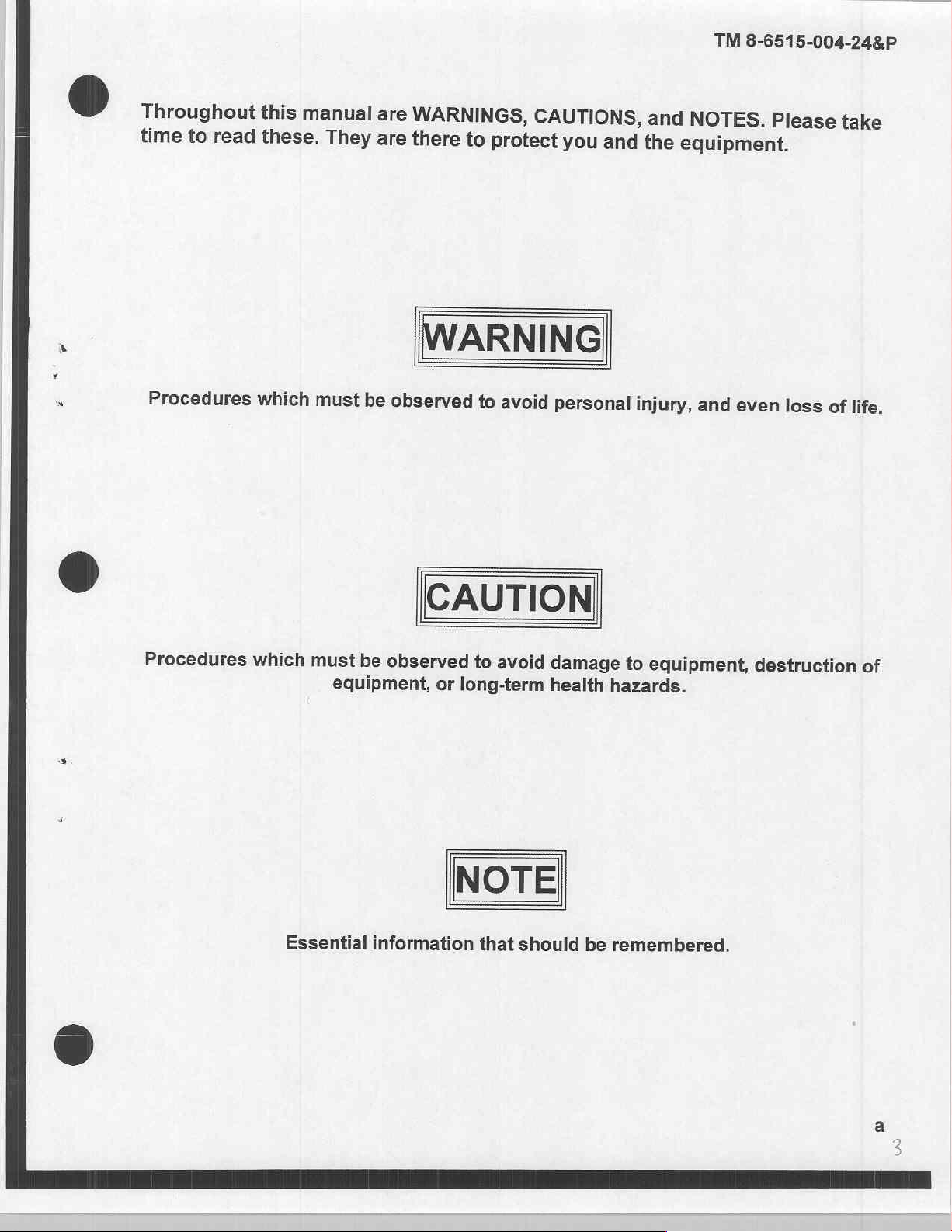
Throughout
time
to
read
Procedures
this
manual
these.
which
They
must
are
are
be
observed
WARNINGS,
there
to
WARNING
to
CAUTIONS,
protect
avoid
you
and
personal
and
NOTES.
the
equipment.
injury,
and
even
Please
loss
take
of
life.
Procedures
which
Essential
must
be
equipment,
information
CAUTION
observed
to
or
long-term
NOTE
avoid
that
damage
health
should
to
equipment,
hazards.
be
remembered.
destruction
of
TM
8-6515-004-24&P
TECHNICAL
NO.
8-6515-004-248P
You
procedures,
Changes
Eguipment
Army
furnished
MANUAL
UNIT,
DIRECT
(INCLUDING
SUCTION
can
help
improve
please
to
Publications
Technical
Medical
Materiel
directly
to
SUPPORT,
MAINTENANCE
REPAIR
APPARATUS,
this
manual.
let
us
know.
and
Blank
Publications)
Agency,
you.
AND
GENERAL SUPPORT
MANUAL
PARTS
AND
OROPHARYNGEAL
MODEL
308M
6515-01-304-6497
If
you
find
any
mistakes
Mail
your
memorandum,
Forms),
located
ATTN:
or
in
SGMMA-M,
DA
Form
the
back
Frederick,
WASHINGTON,
SPECIAL
or
if
DA
Form
2028-2
of
this
manual,
MD
(Recommended
HEADQUARTERS
DEPARTMENT
TOOLS
you
know a way
2028
to:
21702-5001. A reply
OF
DC
LIST)
to
(Recommended
Changes
Commander,
THE
8
October
improve
will
ARMY
1993
to
U.S.
be
CHAPTER
Section
CHAPTER
Section
1.
1.
Il
INI.
2.
1.
|.
Il.
Iv.
V.
Vi.
Approved
HOWTOUSETHISMANUAL.........................
INTRODUCTION
General
Equipment
Principles:of
OPERATING
Preparation
Operating
‘Operating
Operation
Cleaning,
Operation
Information . ...........................,......................
for
public
TABLE
Description
Operation: . νοκ
INFORMATION
for
Operation
Information
Instructions: z à » mesmama
of
AuxiliaryEguipment
Disinfecting,
under
Unusual
release;
OF
and
Data
AND
.........................................,....
.................................................
and
Sterilizing
Conditions.
distribution
CONTENTS
........................................
αν
ες
ηο
INSTRUCTIONS
ses
cas
........................................
Procedures
.....................................
SATER
is
unlimited.
0...
sas
tes
ame
onen
aussi
CLIC
...........................
IL
TALES
Page
iv
1-1
1-3
1-8
2-1
2-1
2-3
2-5
2-6
2-7
TM
8-6515-004-24&P
CHAPTER
Section
CHAPTER
Section
APPENDIX
3.
1.
И.
IR
IV.
V.
M.
VII.
VIII.
IX.
X.
XI.
4.
1.
IL
A.
B.
ο.
Ρ.
E:
UNIT
LEVEL
General
Service
Lubrication
Preventive
Operational
Battery
Troubleshooting
Circuit
Repair
MAINTENANCE
information
Upon
Receipt
Instructions
Maintenance
Testing
Pack
Care
Descriptions
Procedures.
Ge
Maintenance
REFERENCES:
MAINTENANCE
COMPONENTS
EXPENDABLE
REPAIR
Procedures.......................................
AND
PARTS
I
of
Equipment
...........
Checks
............................
and
Recharging................
.
and
LO
Services
ces.
ο
το
ALLOCATION
OF
END
ITEM
DURABLE
AND
SPECIAL
CHART
AND
SUPPLIES
TOOLS
ο
BASIC
AND
LISTS............................
ISSUE
MATERIALS
νι
ντος...
ITEMS
LIST...
LIST
TTI
0.4.4...
44
4-1
GLOSSARY
INDEX
Figure
1-1
1-2
1-3
1-4
1-5
1-6
1-7
1-8
1-9
1-10
1-11
1-12
1-13
No.
SC
lata
Suction
Components
Rinse
Litter
Patient
CAME
ROW
Vehicle
Manufacturer
Operating
Operating
re
ita i e
apparatus
bottle
mounting
suction tube
culos
power
time
Information:
全 四 ON
lee
mg
SIINO
LIST
straps
cos
cord
..
data
plate...
limitation
Stencil...
RO
OF
ILLUSTRATIONS
Title
an
o
decal
emas
.
y
celano
eet
TSE
ca
o
as
I
al
SIT
ce
Seria
ee
ee
SII
Celine
Ia
σσ
SO
GLOSSARY-1
oo
O
ironici
INDEX-1
oa
er
.
..
$
es
o
Page
1-3
1-7
1-7
TM
8-6515-004-24&P
Figure
2-1
2-2
2-3
2-4
2-5
3-1
3-2
3-3
3-4
3-5
3-6
3-7
3-8
3-9
E-1
E-2
E-3
E-4
E-5
E-6
E-7
No.
Operating
NAQUUM
Circuit
Ice
Power
Operating
Vacuum
Operating
Schematic
Vacuum
Pumpiheadi
Vacuum
Battery
Suction
Vacuum
Manifold
Power
mode
AUDE.
breaker . .
transformer
mode
adjust
mode
diagram
pump
pump
pack:
apparatus
pump
......
transformer
Components
control
head
Mt
head
head
selector
selector
selector
cable
......
and
reo
and
coi
with
components
.....
switch.
switch
switch
manifold
ρωσ
manifold
andlaccessones
Title
.........................................
nas
ο
mate
μμ
(front)
το
inn
(front)
72.
ο
еее
ο
отл
ο
οσο.
> :
а
нее
ое
Al
se
ο
+...
Ge
Page
2-1
2-2
2-2
Table
1-1
1-2
1-3
3-1
3-2
3-3
3-4
3-5
3-6
No.
Nomenciature’
Miscellaneous
Specifications.
Transformer
Operator
Repairer
'Operatoruser
Medical
VWiringjintormation!
cross-reference
characteristics
.............
wiring
preventive
connections
preventive
troubieshootingi::
Equipment
51.
LIST
OF
Title
İlt...
......................
.
maintenance
maintenance
ve
Repairer
si
troubleshooting
eve
se
TABLES
<5.
checks
checks
ciar
ame
me не
5...
and!
and
veee
вое
ue.
cs
services.
.
.......................
rea
аль
мя
Page
ee
12
3-5
36
eee
도
alo
ao
3-12
3-13
3-32
TM
8-6515-004-24&P
1-1.
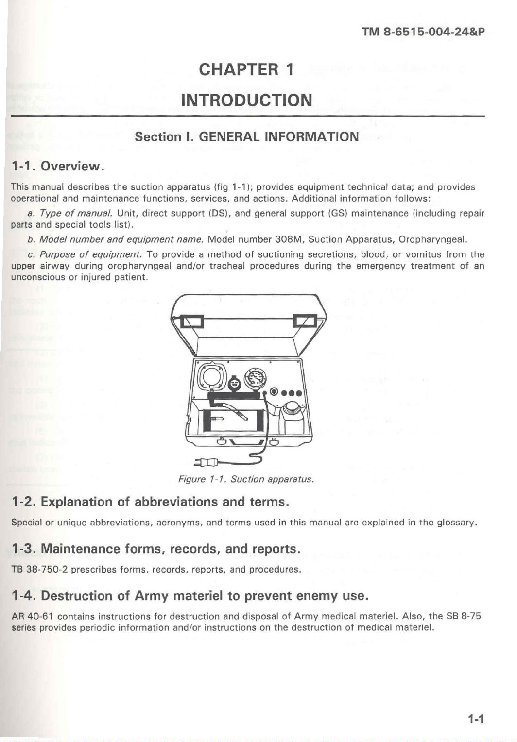
Overview.
This
manual
operational
a.
Type
parts
and
special
b.
Model
c.
Purpose
upper
airway
unconscious
describes
and
maintenance
of
manual.
tools
number
of
equipment.
during
or
injured
Section
the
suction
functions,
Unit,
direct
list).
and
equipment
To
oropharyngeal
patient.
CHAPTER
INTRODUCTION
I.
GENERAL
apparatus
support
name.
provide a method
and/or
(fig
services,
(DS),
Model
tracheal
1-1);
and
and
number
1
INFORMATION
provides
actions.
general
of
suctioning
procedures
Additional
support
308M,
equipment
(GS)
Suction
secretions,
during
technical
information
maintenance
Apparatus,
blood,
the
emergency
data;
and
provides
follows:
(including
Oropharyngeal.
or
vomitus
treatment
from
repair
the
of
an
1-2.
Special
1-3.
TB
38-750-2
1-4.
AR
40-61
series
Explanation
or
unique
abbreviations,
Maintenance
prescribes
Destruction
contains
provides
instructions
periodic
Figure
of
abbreviations
acronyms,
forms,
forms,
of
Army
information
records,
records,
materiel
for
destruction
and/or
1-1.
and
and
terms
and
reports,
to
and
instructions
Suction
terms.
used
reports.
and
procedures.
prevent
disposal
apparatus.
in
this
of
on
the
manual
enemy
Army
medical
destruction
are
explained
use.
materiel.
of
medical
in
the
Also,
the
materiel.
glossary.
SB
8-75
1-1
TM
8-6515-004-24&P
1-5.
maintenance
the
records.
placing
PMCS
1-6.
Procedures
1-7.
TB
1-8.
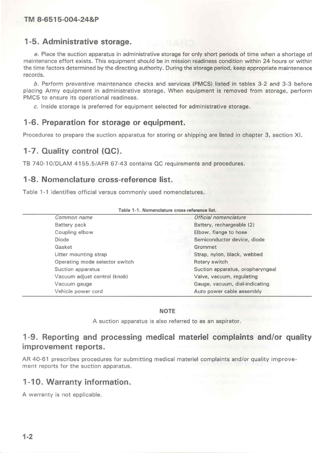
Table
Administrative
a.
Place
time
factors
b.
Perform
Army
to
c.
Inside
Preparation
Quality
740-10/DLAM
Nomenclature
1-1
the
suction
effort
determined
preventive
equipment
ensure
storage
to
prepare
its
control
identifies
Common
Battery
Coupling
Diode
Gasket
Litter
mounting
Operating
Suction
Vacuum
Vacuum
Vehicle
apparatus
exists.
This
by
maintenance
in
operational
is
preferred
for
the
suction
4155.5/AFR
cross-reference
official
name
pack
elbow
apparatus
adjust
gauge
power
mode
versus
strap
selector
control
cord
storage.
in
administrative
equipment
the
directing
checks
administrative
readiness.
for
equipment
storage
or
apparatus
should
authority.
storage.
equipment.
be
and
selected
for
storing
storage
in
mission
During
services
When
or
for
(QC).
67-43
contains
QC
requirements
list.
commonly
Table
switch
(knob) Valve,
1-1.
Nomenclature
used
nomenclatures.
cross-reference
for
only
short
readiness
the
storage
(PMCS)
equipment
administrative
shipping
are
and
list.
Official
Battery,
Elbow,
Semiconductor
Grommet
Strap,
nylon,
Rotary
Suction
Gauge,
Auto
power
periods
condition
period,
listed
procedures.
nomenclature
rechargeable
flange
switch
apparatus,
vacuum,
vacuum,
is
removed
storage.
listed
black,
cable
keep
in
in
to
hose
device,
regulating
dial-indicating
of
time
when a shortage
within
tables
chapter
webbed
oropharyngeal
assembly
24
appropriate
3-2
from
(2)
diode
hours
maintenance
and
3-3
storage,
3,
section
or
within
before
perform
XI.
of
1-9.
Reporting
improvement
AR
40-61
ment
1-10.
A
warranty
prescribes
reports
Warranty
is
for
not
A
and
reports.
procedures
the
suction
information.
applicable.
suction
apparatus
processing
for
submitting
apparatus.
NOTE
is
also
referred
medical
medical
to
as
materiel
materiel
complaints
an
aspirator.
complaints
and/or
and/or
quality
quality
improve-
TM
8-6515-004-24&P
1-11.
use
with
pack.
circuitry.
Equipment
a.
The
in
field
no
electrical
b.
The
c.
Electromagnetic
d.
The
power.
1-12.
the
includes
receptacle.
and
the
deliverable
dual
switch
Component
a.
Components
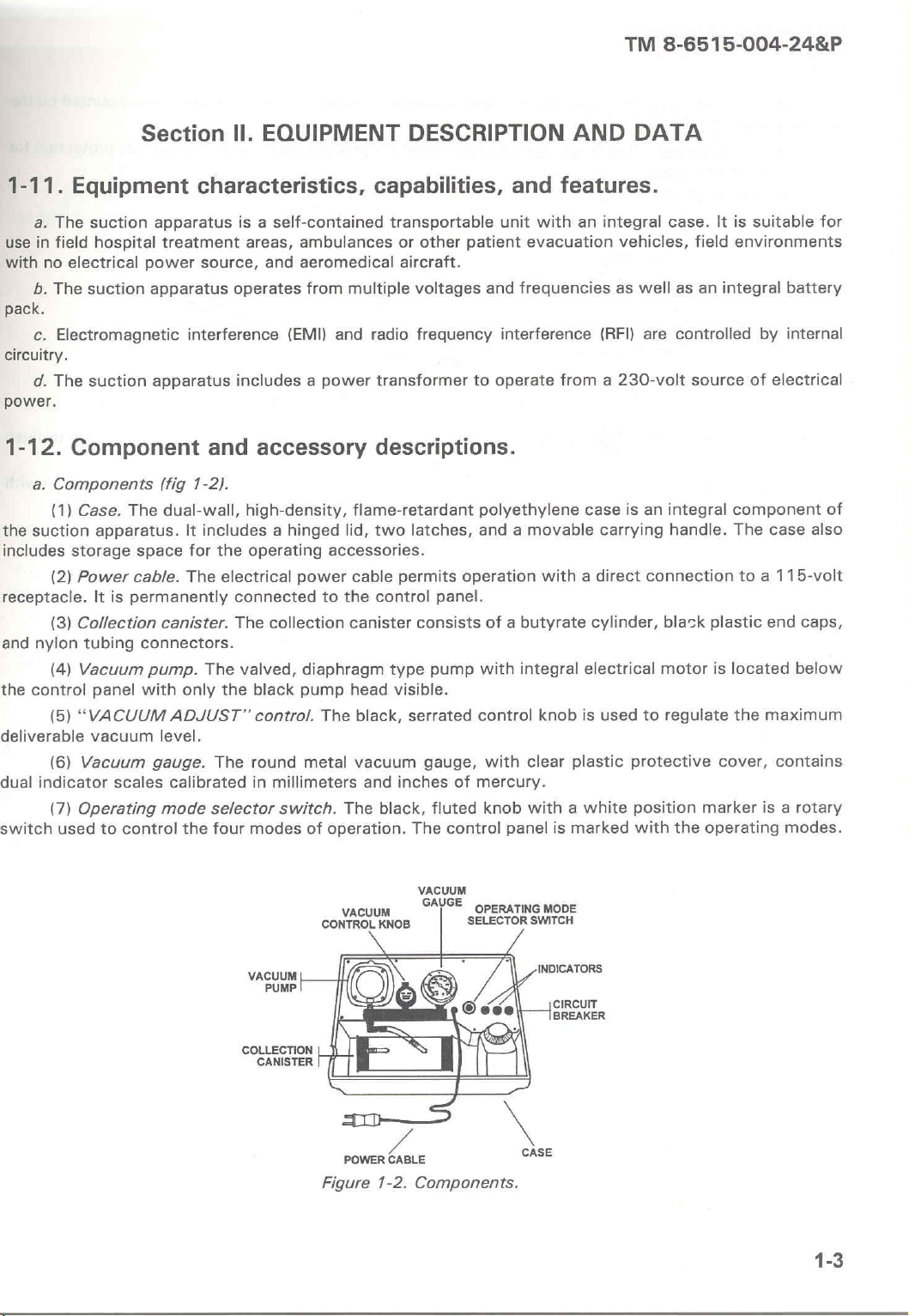
(1)
Case.
suction
storage
(2)
Power
(3)
Collection
nylon
(4)
control
(5)
“VACUUM
(6)
indicator scales
(7)
Operating
used
suction
hospital
suction
suction
The
apparatus.
cable.
It
is
permanently
tubing
Vacuum
panel
vacuum
Vacuum
to
control
Section
characteristics,
apparatus
treatment
power
apparatus
source,
interference
apparatus
and
(fig
1-2).
dual-wall,
It
includes a hinged
space
for
The
canister.
connectors.
pump.
with
gauge.
The
only
ADJUST”
level.
calibrated
mode
selector
the
Il.
EQUIPMENT
is a
self-contained
areas,
operates
includes a power
ambulances
and
aeromedical
(EMI)
accessory
high-density,
the
operating
electrical
connected
The
valved,
the
The
four
power
collection
diaphragm
black
pump
control.
round
in
millimeters
switch.
modes
metal
from
multiple
and
radio
flame-retardant
lid,
accessories.
cable
to
the
canister
head
The
black,
vacuum
and
The
of
operation.
DESCRIPTION
capabilities,
transportable
or
other
aircraft.
voltages
frequency
transformer
and
unit
patient
and
interference
to
operate
descriptions.
polyethylene
two
latches,
permits
control
consists
type
visible.
serrated
gauge,
inches
black,
The
and a movable
operation
panel.
pump
control
of
mercury.
fluted
control
of a butyrate
with
with
knob
panel
AND
features.
with
an
evacuation
frequencies
from a 230-volt
case
with a direct
cylinder,
integral
clear
with a white
knob
is
electrical
is
plastic
marked
DATA
integral
vehicles,
as
well
(RFI)
are
is
an
carrying
connection
used
to
protective
position
with
case.
It
field
as
an
controlled
source
integral
handle.
black
plastic
motor
is
regulate
marker
the
operating
is
suitable
environments
integral
component
The
located
the
cover,
battery
by
internal
of
electrical
case
to a 115-volt
end
maximum
contains
is a
modes.
for
of
also
caps,
below
rotary
COLLECTION
CANISTER
CONTROL
Figure
VACUUM
POWER
VACUUM
KNOB
CABLE
1-2.
Components.
GAUGE
OPERATING
SELECTOR
MODE
SWITCH
INDICATORS
CIRCUIT
BREAKER
CASE
1-3
TM
8-6515-004-24&P
(8)
Indicators.
control
the
panel.
(9)
Circuit
vacuum
b.
Accessories.
pump/motor.
The
breaker.
two
The
control
black,
indicators,
button-type
which
circuit
show
breaker
green
provides
when
illuminated,
excessive
current
are
mounted
protection
on
the
for
4
the
patient
the
D-ring
a
suction
patient
to
accept
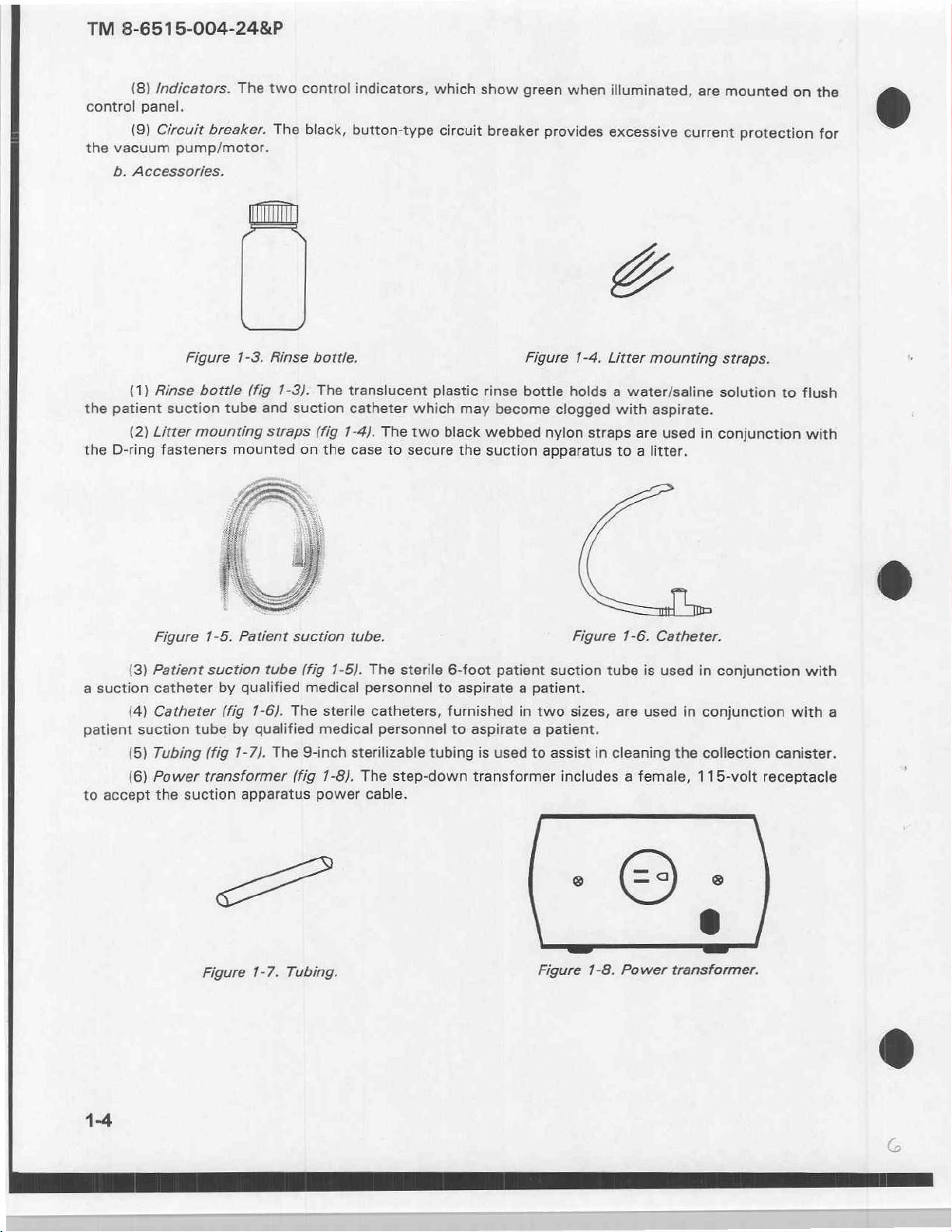
(1)
Rinse
(2)
Litter
fasteners
Figure
(3)
Patient
catheter
(4)
Catheter
suction
(5)
Tubing
(6)
Power
the
Figure
bottle
suction
mounting
1-5.
suction
tube
(fig
transformer
suction
1-3.
(fig
tube
mounted
Patient
by
qualified
(fig
1-6).
by
1-7).
apparatus
Rinse
1-3).
and
suction
straps
on
suction
tube
(fig
medical
The
qualified
The
9-inch
(fig
bottle.
The
translucent
catheter
(fig
1-4).
the
case
tube.
1-5).
sterile
medical
sterilizable
1-8).
power
which
The
two
to
secure
The
sterile
personnel
catheters,
personnel
The
step-down
cable.
Figure
plastic
tubing
rinse
bottle
may
become
black
webbed
the
suction
6-foot
to
furnished
patient
aspirate a patient.
in
to
aspirate a patient.
is
used
transformer
1-4.
Litter
holds a water/saline
clogged
nylon
apparatus
suction
two
to
assist
includes a female,
straps
Figure
tube
sizes,
in
with
to a litter.
1-6.
are
cleaning
mounting
aspirate.
are
used
Catheter.
is
used
used
the
straps.
solution
in
conjunction
in
conjunction
in
conjunction
collection
115-volt
to
flush
with
with
with
canister.
receptacle
a
aa
Figure
1-7.
Tubing.
Figure
1-8.
Power
transformer.
TM
8-6515-004-24&P
dip
The
try
(7)
Vehicle
to
operate
the
The
be
removed
tactical
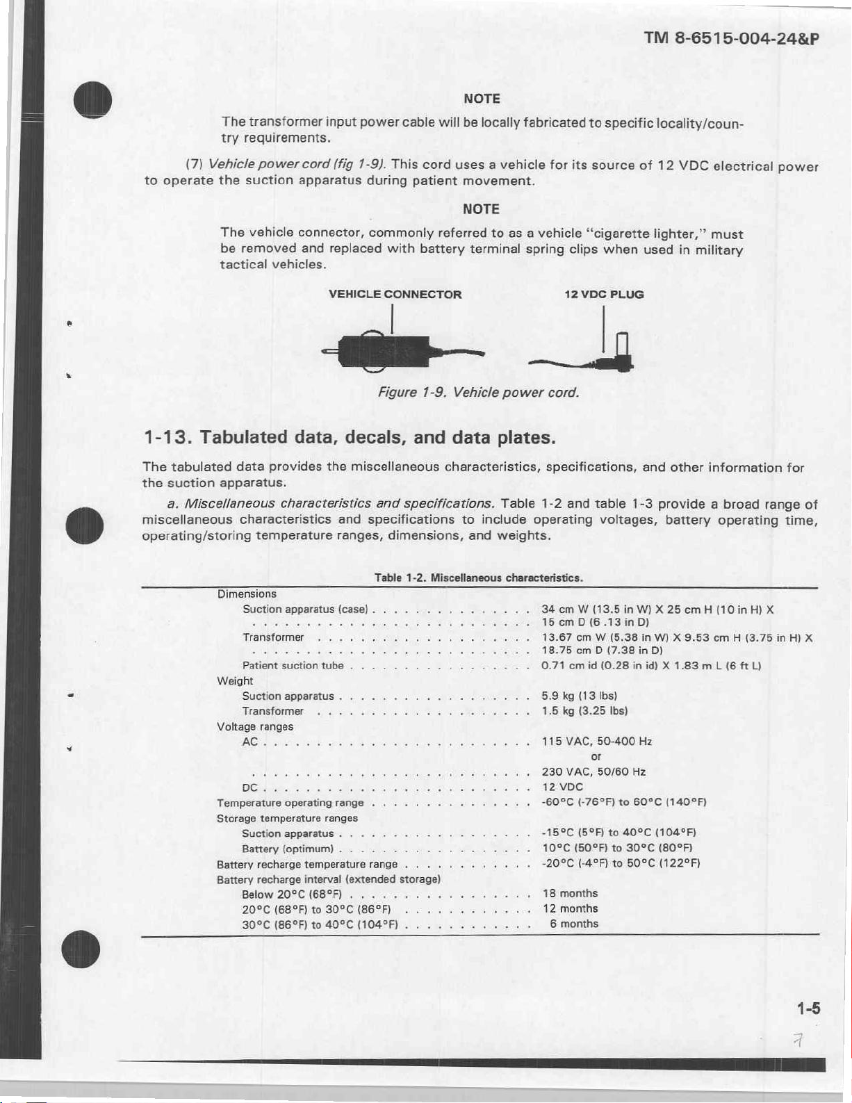
1-13.
The
the
miscellaneous
operating/storing
Tabulated
tabulated
suction
a.
apparatus.
Miscellaneous
data
characteristics
transformer
requirements.
power
suction
vehicle
cord
apparatus
connector,
and
vehicles.
om—
data,
provides
characteristics
temperature
input
power
(fig
1-9).
during
commonly
replaced
VEHICLE
Figure
decals,
the
miscellaneous
and
and
specifications
ranges,
cable
will
This
cord
patient
referred
with
battery
CONNECTOR
1-9.
and
data
characteristics,
specifications.
dimensions,
NOTE
be
locally
uses
a
vehicle
movement.
NOTE
to as a vehicle
terminal
Vehicle
power
plates.
Table
to
include
and
weights.
fabricated
for
its
spring
clips
12
_
cord.
specifications,
1-2
and
operating
to
specific
source
“cigarette
when
VDC
PLUG
table
voltages,
locality/coun-
of
12
VDC
lighter,”
used
in
military
and
other
1-3
provide a broad
battery
electrical
must
information
range
operating
power
for
of
time,
-
Table
1-2.
Dimensions
Suction
Patient
apparatus
suction
tube
(case) . .
. . . .
Miscellaneous
. .
. .
. . . . . . . . . 34
.............
characteristics.
ст W (13.5
15
cm D (6
13.67
cm W (5.38
18.75
cm D (7.38
0.71
cm
id
in
W) X 25
.13
in
D)
in
(0.28
in
cm H (10
in
W) X 9.53
D)
id) X 1.83
in
cm H (3.75
mL
(6
ft
H) X
L)
in
H)
X
Weight
Suction
Transformer
Voltage
AGA
Temperature
Storage
Suction
Battery
Battery
Battery
Below
20°C
30°C
apparatus . .
ranges
sie
eal:
qua
operating
temperature
apparatus . .
(optimum) . .
recharge
recharge
20°C
(68°F)
(86°F)
range . . . . . .
ranges
temperature
interval
(68°F) . . < <- +-
to
30°C
to
40°C
5.9
kg
1.5
М
al
hace
's
kg
115
230
12
VDC
. . . . . .
range
.............
(extended
(86°F) . .
(104°F) . . . . . . . . . . . . 6 months
storage)
+ 4 4 4 « ve
. . . . .. + + + + 12
...
ie
se
ve
-60°C
-15°C
10°C
-20°C
18
months
months
(13
Ibs)
(3.25
VAC,
50-400
or
VAC,
50/60
(-76°F)
(5°F)
(50°F)
(-49F)
Ibs)
Hz
to
60°C
to
40°C
to
30°C
to
509C
Hz
(140°F)
(104°F)
(80°F)
(1229F)
TM
8-6515-004-24&P
b.
depicted
Vacuum
Airflow
Collection
Operating
Use
its
Identification,
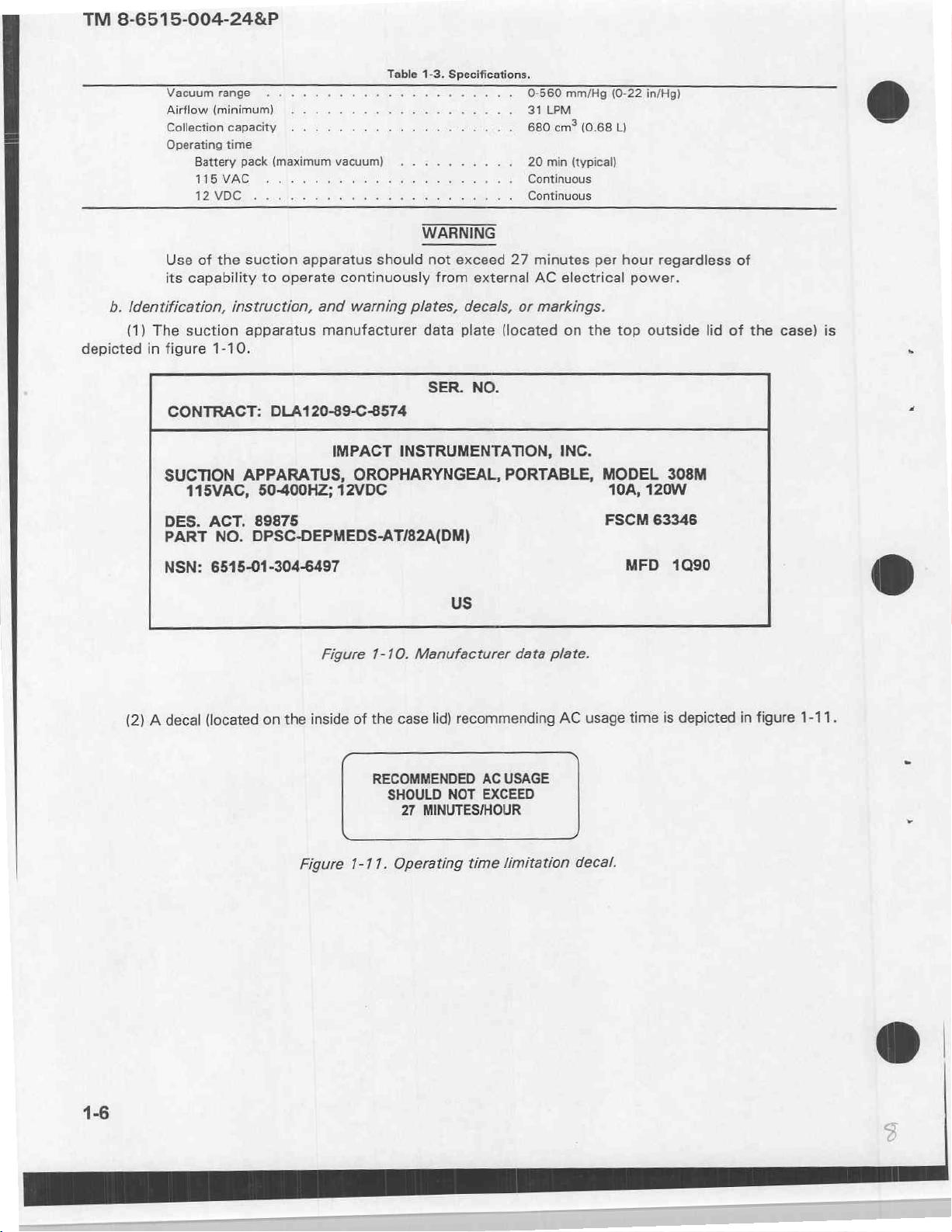
(1)
The
in
figure
CONTRACT:
SUCTION
range . ........
(minimum)
capacity
time
Battery
pack
(maximum
TIBMAC
DUO
of
the
capability
suction
1-10.
115VAC,
κ
ών
λος
suction
to
operate
instruction,
apparatus
DLA120-89-C-8574
APPARATUS,
50-400HZ;
.....
ο
vacuum)
ας
ο
apparatus
and
manufacturer
IMPACT
12VDC
Table
1-3.
ο
ο
Te
ya
eli
WARNING
should
continuously
warning
OROPHARYNGEAL,
not
plates,
data
SER.
INSTRUMENTATION,
Specifications,
0-560
31
LPM
ο
ο
as
680 cm“
20
min
=
È
Continuous
ve
exceed
from
plate
external
decals,
(located
NO.
PORTABLE,
.
Continuous
27
minutes
AC
or
markings.
mm/Hg
(0-22
(0.68
L)
(typical)
per
hour
electrical
on
INC.
the
MODEL
power.
top
10A,
in/Hg)
regardless
outside
308M
120W
lid
of
of
the
case)
is
a
<
DES.
PART
NSN:
(2) A decal
ACT.
89875
NO.
DPSC-DEPMEDS-AT/82A(DM)
6515-01-304-6497
Figure
(located
on
the
Figure
inside
of
1-11.
1-10.
Manufacturer
the
case
lid)
RECOMMENDED
SHOULD
27
Operating
NOT
MINUTES/HOUR
us
data
recommending
AC
USAGE
EXCEED
time
limitation
plate.
AC
usage
decal.
FSCM
MFD
time
63346
1090
is
depicted
in
figure
©
1-11.
TM
8-6515-004-24&P
da
è
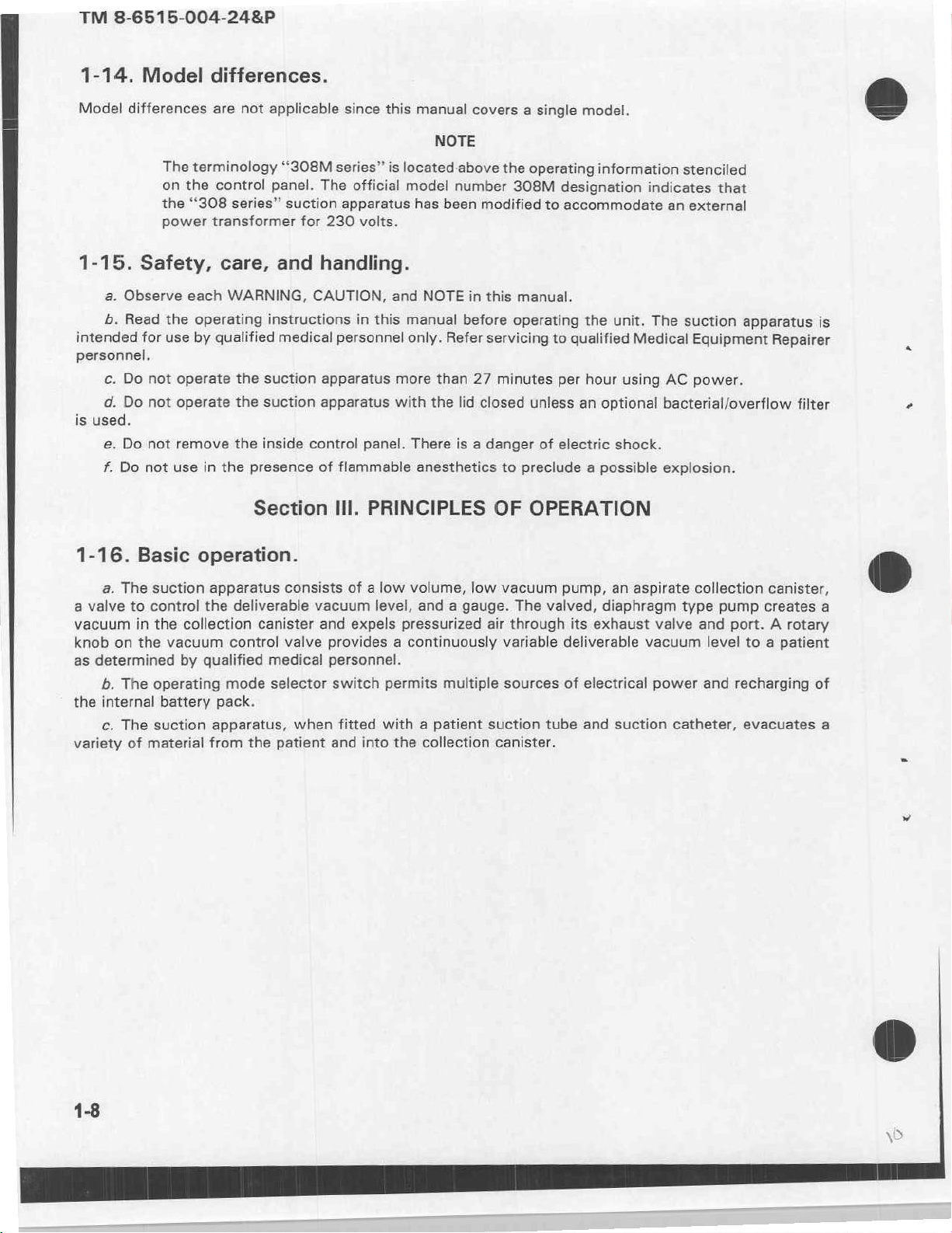
(3)
(4)
lepicted
Operating
The
power
in
figure
information
Recharge
Use
Use
not readily
Do
Pump
use.
To
not
Do
transformer
1-13.
(located
external
internal
not
use
head
This
will
protect
operate
not
clean
Figure
manufacturer
on
«
batteries
available.
in
may
this
with
as
AC
or
external
rechargeable
the
presence of
become
not
effect
device
lid
closed
cannister(s)
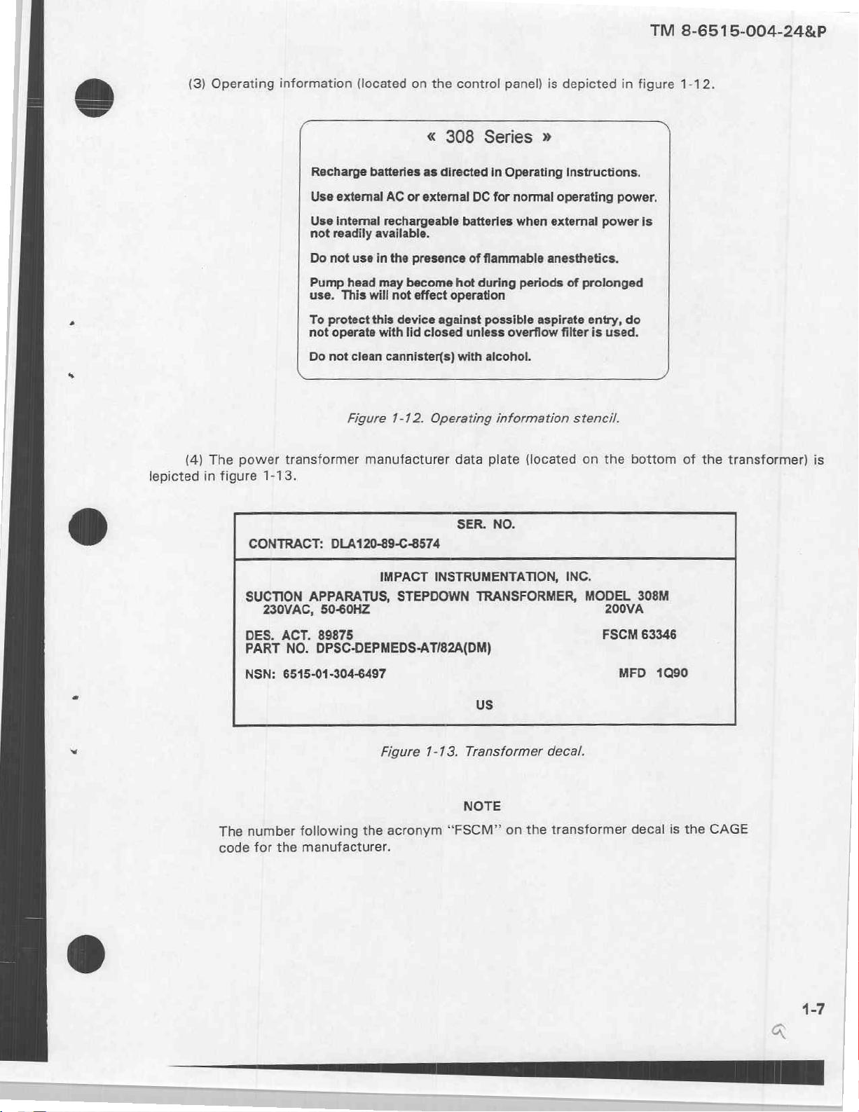
1-12.
the
control
308
directed
DC
batteries
flammable
hot
during
operation
against
unless
with
Operating
data
panel)
Series
in
Operating
for
normal
when
periods
possible
alcohol.
plate
aspirate
overflow
information
(located
is
depicted
»
Instructions.
operating
external
anesthetics.
of
prolonged
entry,
filter
is
stencil.
on
in
power.
power
do
used.
the
figure
is
bottom
1-12.
of
the
transformer)
is
dh
É
CONTRACT:
SUCTION
DES.
PART
NSN:
The
number
code
DLA120-89-C-8574
APPARATUS,
230VAC,
50-60HZ
ACT.
89875
NO.
DPSC-DEPMEDS-AT/82A(DM)
6515-01-304-6497
following
for
the
manufacturer.
IMPACT
Figure
the
STEPDOWN
1-13.
acronym
SER.
NO.
INSTRUMENTATION,
TRANSFORMER,
us
Transformer
NOTE
“FSCM”
on
the
INC.
MODEL,
FSCM
decal.
transformer
Fed
MFD
decal
63346
1090
is
the
CAGE
TM
8-6515-004-24&P
1-14.
Model
differences
1-15.
a.
Observe
b.
Read
intended
personnel.
c.
Do
d.
Do
is
used.
e.
Do
f.
Do
Model
The
terminology
the
on
“308
the
power
Safety,
each
the
operating
for
use
by
not
operate
not
operate
not
remove
not
use
in
differences.
are
not
applicable
“308M
control
transformer
panel.
series”
care,
WARNING,
instructions
qualified
the
suction
the
suction
the
inside
the
presence
The
suction
for
and
handling.
CAUTION,
medical
apparatus
apparatus
control
of
230
Section
since
this
series”
apparatus
is
official
volts.
and
in
this
personnel
more
with
panel.
flammable
Ill.
PRINCIPLES
manual
covers a single
NOTE
located-above
model
manual
only.
number
been
has
NOTE
There
anesthetics
before
Refer
than
the
lid
is a danger
in
27
modified
this
servicing
closed unless
model.
the
operating
308M
to
information
designation
accommodate
manual.
operating
minutes
to
preclude a possible
OF
OPERATION
to
qualified
per
of
electric
the
hour
an
indicates
unit.
Medical
using
optional
shock.
stenciled
that
external
an
The
suction
Equipment
AC
power.
bacterial/overflow
explosion.
apparatus
is
Repairer
filter
1-16.
a.
a
valve
vacuum
knob
on
as
determined
b.
the
internal
c.
variety
Basic
The
to
in
the
The
The
of
operation.
suction
control
the
collection
vacuum
by
operating
battery
suction
material
apparatus
the
deliverable
canister
control
qualified
mode
pack.
apparatus,
from
the
consists
vacuum
valve
medical
selector
when
patient
of a low
and
expels
provides a continuously
personnel.
switch
fitted
and
into
volume,
level,
and a gauge.
pressurized
permits
multiple
with a patient
the
collection
low
vacuum
air
variable
suction
canister.
The
valved,
through
sources
tube
pump,
an
diaphragm
its
exhaust
deliverable
of
electrical
and
suction
aspirate
type
valve
vacuum
power
catheter,
collection
pump
and
port. A rotary
level
to a patient
and
recharging
evacuates
canister,
creates
of
a
a
TM
8-6515-004-24&P
ab
OPERATING
2-1.
This
nance
sufficient
trained
2-2.
Scope.
manual
of
in
Assembly
a.
Assembly.
b.
Interconnections.
is
primarily
the
suction
information
specific
The
a
suctioning
No
aspiration
suction
INFORMATION
Section
intended
apparatus.
for
use
and
assembly
No
of
catheter
|.
to
provide
The
of
the
suction
techniques
interconnections.
is
required
interconnections
patients
to
the
CHAPTER
PREPARATION
information,
operating
will
collection
apparatus
and
procedures.
prior
are
require
information
to
operating
required
NOTE
the
connection
canister
2
AND
FOR
instructions,
and
on a patient.
prior
tubing
OPERATION
instructions,
the
suction
to
operating
of a patient
connector.
INSTRUCTIONS
and
Only
procedures
while
qualified
apparatus.
the
suction
valid,
medical
suction
tube
for
do
apparatus.
the
mainte-
not
provide
personnel
and
are
(bh
©
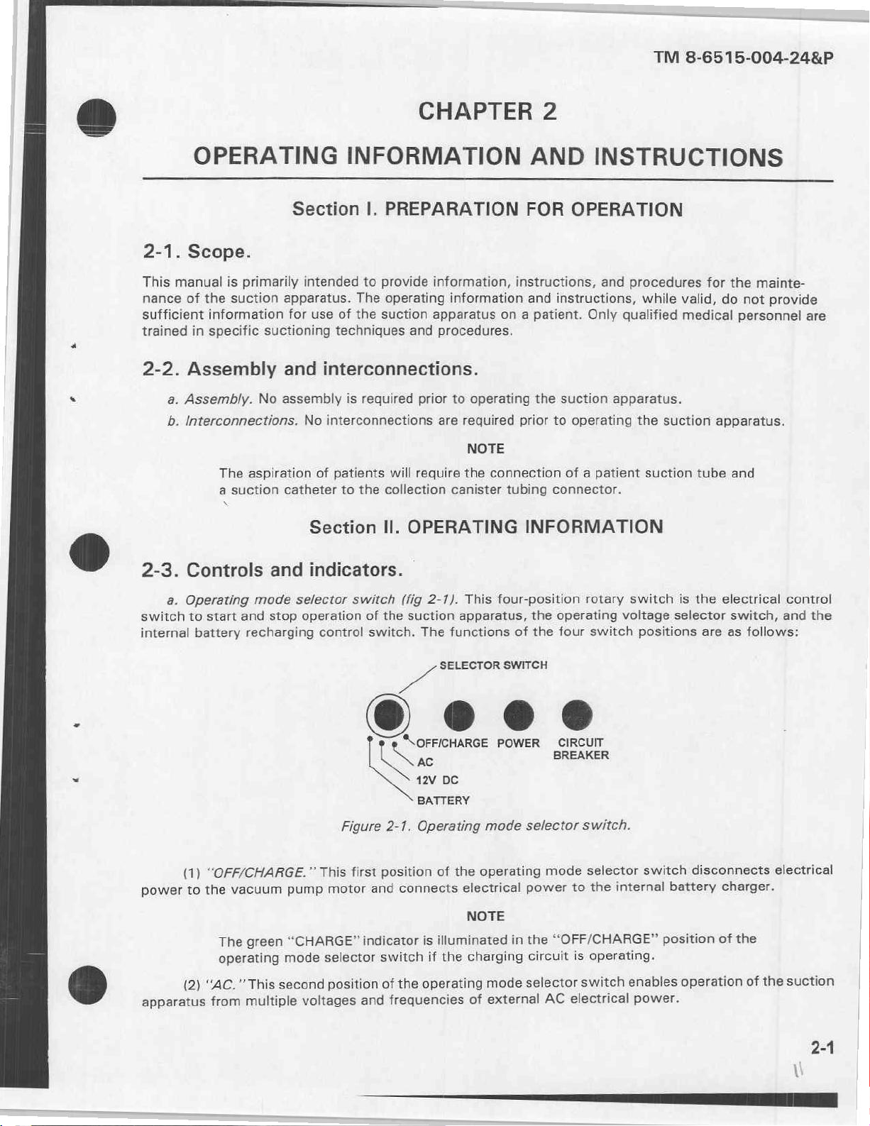
2-3.
switch
internal
power
apparatus
Controls
a.
Operating
to
battery
(1)
to
(2)
and
mode
start
and
stop
recharging
“OFF/CHARGE.”
vacuum
the
green
The
operating
second
"This
“AC,
multiple
from
Section
indicators.
selector
operation
pump
“CHARGE”
mode
voltages
control
This
motor
selector
position
switch
Figure
first
Il.
OPERATING
(fig
2-1).
of
the
suction
switch.
The
A
‘\OFFICHARGE
SS
ne
12V
BATTERY
2-1.
Operating
position
connects
and
indicator
switch
and
is
operating
the
of
frequencies
This
apparatus,
functions
SELECTOR
DC
mode
operating
the
of
electrical
NOTE
illuminated
charging
the
if
mode
of
INFORMATION
four-position
the
of
the
SWITCH
POWER
BREAKER
selector
mode
power
“OFF/CHARGE”
the
in
circuit
selector
external
AC
rotary
operating
four
switch
CIRCUIT
switch.
selector
internal
the
to
operating.
is
switch
electrical
switch
voltage
positions
switch
enables
power.
is
the
selector
are
disconnects
battery
position
operation
electrical
switch,
as
follows:
charger.
the
of
the
of
control
and
the
electrical
suction
TM
8-6515-004-24&P
The green
mode
(3)
“72V DC.”
suction
apparatus
The
operating
(4)
“BATTERY.”
suction
the
by
canister
vacuum
pinched
indicated
apparatus
6.
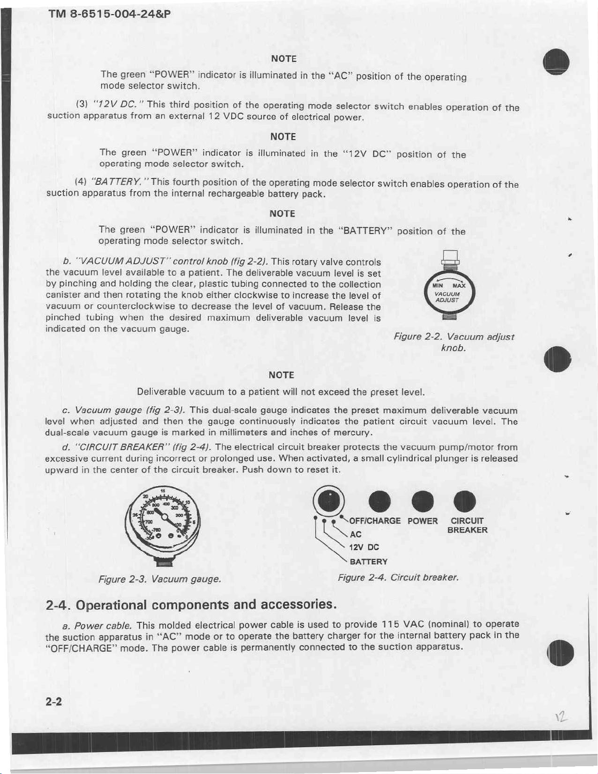
“VACUUM
vacuum
pinching
and
or
tubing
on
The green
operating
level
and
then
counterclockwise
the
selector
This
from
green
mode
This
from
mode
ADJUST”
available
holding
rotating
when
vacuum
“POWER”
switch.
third
an
external
“POWER”
selector
fourth
internal
the
“POWER”
selector
control
to a patient.
the
clear,
the
knob
to
the
desired
gauge.
indicator
position
12
VDC
indicator
switch.
position
rechargeable
indicator
switch.
knob
The
plastic
either
decrease
maximum
is
illuminated
of
the
source
is
illuminated
of
the
is
illuminated
(fig
2-2).
deliverable
tubing
connected
clockwise
the
level
deliverable
NOTE
in
operating
of
electrical
NOTE
operating
battery
pack.
NOTE
This
rotary
vacuum
to
increase
of
vacuum.
the
mode
in
the
mode
in
the
valve
to
the
vacuum
“AC”
position
selector
power.
“12V
selector
“BATTERY”
controls
level
is
collection
the
level
Release
level
switch
DC”
switch
set
of
the
is
of
the
enables
position
enables
position
Figure
operating
operation
of
the
operation
of
the
2-2.
Vacuum
knob.
of
the
of
the
adjust
c.
Vacuum
level
when
dual-scale
d.
excessive
upward
2-4.
a.
suction
the
“OFF/CHARGE”
vacuum
“CIRCUIT
current
in
the
Operational
Power
gauge
adjusted
gauge
BREAKER”
during
center
Figure
apparatus
2-3.
cable.
mode.
Deliverable
(fig
2-3).
and
then
is
marked
(fig
incorrect
of
the
circuit
Vacuum
components
This
molded
“AC”
in
power
The
vacuum
This
dual-scale
the
gauge
in
2-4).
The
or
prolonged
breaker.
gauge.
electrical
or
mode
cable
to a patient
gauge
continuously
millimeters
electrical
use.
Push
and
accessories.
power
operate
to
permanently
is
NOTE
will
and
circuit
When
down
cable
the
not
exceed
indicates
indicates
inches
of
breaker
activated, a small cylindrical
to
reset
the
the
preset
the
mercury.
protects
it.
preset
maximum
patient
the
‘\OFFICHARGE
SN
RE
12V
DC
BATTERY
Circuit
2-4.
provide
for
the
to
115
internal
the
suction
is
used
battery
connected
Figure
to
charger
level.
circuit
vacuum
POWER
breaker.
VAC
apparatus.
deliverable
vacuum
pump/motor
plunger
level.
is
CIRCUIT
BREAKER
(nominal)
battery
to
pack
vacuum
The
from
released
operate
the
in
©
2-2
b.
operation
for
Electrical
of
jack.
the
This
two-conductor
suction
apparatus
electrical
the
in
“12V
jack
DC”
is
used
mode.
to
provide
12
TM
8-6515-004-24&P
VDC
from
an
external
source
2-5.
a.
on
its
4.
c.
d.
2-6.
a.
Unlatch
hinges
its
on
4.
follows:
(1)
(2)
(3)
c.
Ensure
d.
power.
Initial
Unlatch
hinges
Ensure
Connect
Recharge
start-up
the
until
that
the
the
Routine
the
until
Determine
hospital
Field
Do
not
hazard.
Ambulance
Litter—internal
that
Connect
either
Section
case
by
pulling
fully
open.
the
operating
power
start-up
case
fully
the
use
the
cable
internal
by
pulling
open.
location
treatment
in
or
other
battery
operating
the
power
III.
procedures.
the
two
mode
selector
to a 115-volt
battery
the
pack
procedures.
the
two
of
use
for
or
area
presence
evacuation
pack.
mode
selector
cable
or
OPERATING
black
plastic
switch
electrical
for
approximately
black
plastic
suction
the
ward—AC
WARNING
of
flammable
vehicle—DC
switch
the
vehicle
latches
latches
apparatus
electrical
(12
is
INSTRUCTIONS
forward.
is
in
the
“OFF/CHARGE”
receptacle.
16
hours.
forward.
and
power.
anesthetics
V)
in
the
power
to
electrical
“OFF/CHARGE”
cord
to
Then,
Then,
mode
the
preclude
power.
an
appropriate
lift
the
position.
lift
the
of
an
position.
lid
of
the
lid
of
the
electrical
explosion
source
case
upward
case
upward
operation
of
electrical
as
e.
Verify
in
place.
f.
Turn
required.
g.
Pinch
“VACUUM
h.
Qualified
collection
The
that
all
No
kinks
the
operating
The
vacuum
illuminate.
and
hold
ADJUST”
medical
canister
“CHARGE”
tubing
should
the
control
and
aspirate
connections
be
in
the
mode
selector
pump
clear,
will
plastic
knob
Deliverable
personnel
the
indicator
are tight
connecting
switch
start
operating
tubing
to
the
desired
vacuum
will
connect
patient.
will
illuminate
and
tubing.
to
connected
will
the
NOTE
that
either
the
NOTE
and
maximum
NOTE
not
exceed
patient
when
connected
the
black
“AC,”
the
green
to
the
deliverable
the
suction
to
collection
“12V
DC,”
“POWER”
collection
vacuum
preset
level.
tube
and a suction
115
VAC.
canister
or
“BATTERY”
indicator
canister
level.
end
caps
will
and
then
Release
catheter
are
firmly
position
rotate
the
tubing.
to
2-3
as
the
the
TM
8-6515-004-24&P
Do
operation
Do
optional
Do
power.
i.
During
collection
canister
not
block
not
operate
overflow
not
use
operation
for
or
occlude
of
the
suction
the
the
suction
of
the
potential
the
suction
safety
suction
overflow.
exhaust
apparatus.
apparatus
device
apparatus
is
apparatus,
WARNING
port
of
CAUTION
with
used.
for
more
periodically
the
the
than
vacuum
lid
27
observe
pump
of
the
minutes
case
the
to
preclude
closed
per
vacuum
hour
incorrect
unless
using
gauge
an
AC
setting
and
the
2-7.
aspiration
used
D-rings
2-8.
Procedures
patient,
Operating
a.
The
b.
Multiple
c. À standard
on a “crash
d.
Two
(located
Changing
are
a.
Pinch
b.
Rotate
gauge.
rinse
to
flush
The
when
collection
litter
to
change
as
follows:
and
the
hints.
bottle,
out a clogged
rinse
bottle
not
in
use.
hospital
cart.”
mounting
on
the
This
front
maximum
the
hold
the
“VACUUM
holding a water
patient
containing
canisters
style
collection
will
straps
and
may
afford
with
back
water
be
of
deliverable
maximum
clear,
plastic
ADJUST”
deliverable
tubing
and
saline
suction
tube
CAUTION
and
saline
connected,
canister
greater
hook-and-loop
the
should
collection
case)
to
vacuum
vacuum
connected
contro!
knob
NOTE
solution,
or
suction
solution
in
series,
be
considered
capacity
fasteners
mount
level,
to
until
the
the
the
should
should
if a large
always
catheter.
always
and
will
be
suction
level.
during
use
collection
new
setting
be
be
quantity
for
use
indicate
used
in
apparatus
of
the
canister.
is
available
tightly
of
if
aspirate
conjunction
suction
displayed
closed
aspirate
the
suction
to a litter.
apparatus
volume.
during
is
anticipated.
apparatus
with
on
the
patient
the
four
on
a
vacuum
is
c.
2-9.
Mount
Rotating
control
Release
the
Rotating
tubing
vacuum
Mounting
the
suction
the
control
knob
counterclockwise
pinched
the
“VACUUM
connected
level
to
the
suction
apparatus
knob
tubing
and
ADJUST”
to
the
collection
an
unknown
onto a litter
clockwise
increases
decreases
resume
aspirating
WARNING
control
canister,
setting.
apparatus.
by
completing
the
vacuum
the
knob,
will
the
the
level
patient.
without
change
following
of
vacuum
level.
pinching
the
procedures:
and
the
maximum
rotating
clear,
plastic
deliverable
the
the
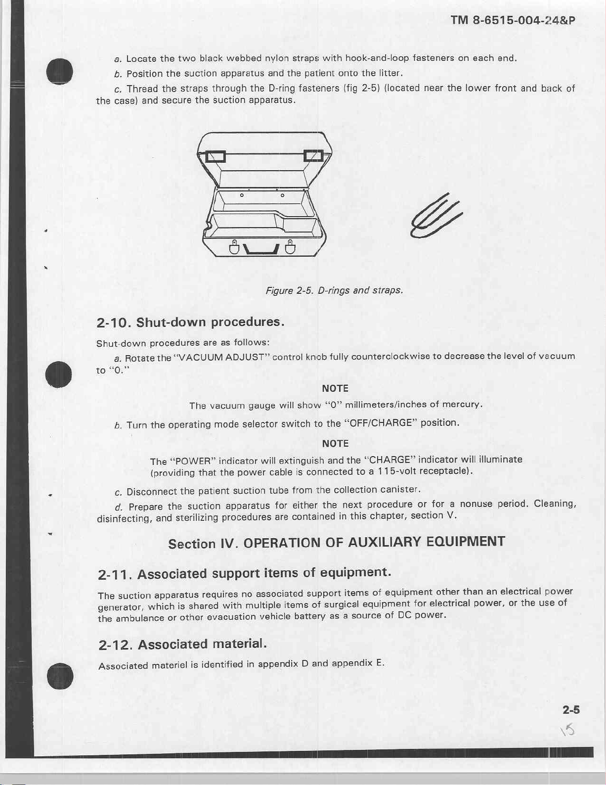
a,
Locate
b.
Position
c.
Thread
case)
and
the
two
the
the
straps
secure
black
suction
through
the
webbed
apparatus
suction
nylon
and
the
the
D-ring
apparatus.
straps
patient
fasteners
with
hook-and-loop
onto
(fig
the
2-5)
litter.
(located
fasteners
near
the
TM
8-6515-004-24&P
on
each
end.
lower
front
and
back
of
2-10.
Shut-down
to
disinfecting,
2-11.
The
generator,
the
Shut-down
Rotate
a.
“0.”
Turn
b.
Disconnect
c.
Prepare
d.
Associated
suction
ambulance
procedures
the
The
(providing
which
“VACUUM
the
The
operating
“POWER”
the
suction
the
sterilizing
and
Section
apparatus
shared
is
other
or
procedures.
are
as
follows:
ADJUST”
vacuum
mode
that
patient
gauge
selector
indicator
power
the
suction
apparatus
procedures
OPERATION
IV.
support
with
no
multiple
requires
evacuation
Figure
will
2-5.
control
will
switch
extinguish
is
cable
from
tube
either
for
contained
are
items
associated
items
vehicle
battery
D-rings
fully
knob
NOTE
show
“O”
the
to
NOTE
and
connected
collection
the
the
OF
equipment.
of
support
surgical
of
as
and
straps.
counterclockwise
millimeters/inches
“OFF/CHARGE”
“CHARGE”
the
115-volt
a
to
canister.
procedure
next
chapter,
this
in
AUXILIARY
equipment
of
items
equipment
DC
source
a
of
decrease
to
of
mercury.
position.
indicator
receptacle).
a
for
or
section
V.
EQUIPMENT
other
electrical
for
power.
illuminate
will
nonuse
than
power,
level
the
period.
electrical
an
or
vacuum
of
Cleaning,
use
the
power
of
2-12.
Associated
Associated
materiel
material.
identified
is
appendix
in
D
and
appendix
E.
TM
8-6515-004-24&P
Section
2-13.
disinfecting,
designed
2-14.
“OFF/CHARGE”
non-abrasive
General.
a.
The
b.
Accessories
and
c.
The
Suction
a.
Cleaning.
(1)
Turn
(2)
Disconnect
(3)
Remove
(4)
Wipe
suction
collection
Do
control
V.
CLEANING,
apparatus
and/or
sterilizing
identified
manufactured
canister
apparatus.
off
the
position.
either
the
collection
the
interior
cleanser
not
with a damp
immerse
panel.
and
procedures
as
for
should
suction
the
and
the
DISINFECTING,
operating
disposable
one
use
be
apparatus
power
canister,
exterior
cloth.
suction
accessories
are
should
only.
removed
cable
or
rinse
of
the
apparatus
provided
by
the
bottle,
WARNING
in
not
be
from
the
turning
vehicle
and
suction
in a liguid
AND
should
subsequent
the
apparatus
STERILIZING
be
cleaned
case
to
operating
power
all
other
or
allow
clean
at
paragraphs.
and
reused.
facilitate
cord.
cleaning.
mode
accessories.
case
and
liguid
to
PROCEDURES
all
times.
These
selector
control
leak
panel
below
Specific
accessories
switch
using a mild,
the
cleaning,
were
to
the
δι
i
(5)
(6)
(7)
(8)
b.
Disinfecting.
it
with
c.
Sterilizing.
2-15.
a.
Cleaning.
(1)
(2)
(3)
(4)
Dry
the
suction
Reinstall
Replace
Prepare
disinfectant
the
all
the
The
Collection
Disconnect
Proceed
Connect
Dispose
Disassemble
the
of
apparatus
collection
other
accessories
suction
Disinfect
in
accordance
suction
canister.
the
tubing
slowly
9-inch
the
the
and
aspirate
collection
All
canister.
apparatus
the
suction
with
apparatus
from
carefully
section
in
tubing
with a soft
into
the
for
either
apparatus
standard
cannot
both
collection
to
prevent
tubing
of
accordance
canister
is
disposable
cloth.
case.
the
unit
be
CAUTION
both
to
with
removing
by
WARNING
next
procedure
by
wiping
procedures.
sterilized.
canister
accidentally
collection
standard
the
and
intended
or
it
with a liquid
connectors.
spilling
canister
procedures.
unit
end
two
for
one
for a nonuse
disinfectant
any
patient
connectors.
caps.
use.
period.
or
lightly
aspirate.
δν
spraying
(5)
Clean
collection
the
canister
cylinder
and
end
caps
accordance
in
with
standard
procedures.
unit
M
TM
8-6515-004-248P
dy
ーー Do
b.
procedures.
*
ec.
unit
procedures.
2-16.
not
hydrocarbon
(6)
Wipe
the
Disinfecting.
Routine
aspirate
procedures
amount
Sterilizing
(ethylene
Section
General.
clean
the
cylinder
agents.
collection
Disinfect
canister
the
disinfection
can
be
accomplished
(para
2-6)
of
disinfectant
oxide
Do
not
VI.
OPERATION
with
cylinder
collection
of
the
and
directly
(EtO)
steam
sterilize
WARNING
abrasive
and
canister
collection
using a spray
while
the
into
the
only).
Sterilize
WARNING
(autoclave)
UNDER
cleansing
end
caps
with a liquid
NOTE
canister
vacuum
collection
which
disinfectant.
pump
the
collection
the
UNUSUAL
agents,
with a soft
or
spray
does
Follow
is
operating,
canister.
canister
collection
alcohol,
cloth.
not
or
disinfectant
involve
the
routine
spray a small
in
accordance
canister.
CONDITIONS
chlorinated
using
standard
removing
start-up
with
unit
standard
The
suction
cility,
within
environment,
tive
barrier
2-17.
to
-20°C
Operating
a.
The
60°C
(-76°F
b.
The suction
to
suction
50°C
apparatus
an
ambulance
precautions
(plastic
The
protective
apparatus
to
(-4°F
is a transportable
or
other
should
sheet,
tarpaulin,
barrier
temperature
should
140°F).
apparatus
to
should
122°F).
evacuation
be
taken
etc.).
will
not
not
not
device
to
protect
interfere
range.
be
operated
be
recharged
designed
vehicle,
the
WARNING
with
when
to
operate
and with a litter.
suction
safe
operation
the
temperature
when
the
within a field
apparatus
of
temperature
When
the
by
covering
suction
is
not
medical
it
is
operated
apparatus.
within
is
not
treatment
in a wet
it
with a protec-
the
range
within
the
of
-60°C
range
fa-
of
2-7
TM
8-6515-004-24&P
3-1.
unit
personnel
checking
operator
disassembly
Overview.
a.
Unit
level
on
its
assigned
(1)
Operator
and
for
accessories,
or
maintenance.
equipment.
maintenance.
consists
frayed
cables, and
assembly
of
and
tools.
(2)
Specialist
Medical
Equipment
(a)
Scheduling
fication/certification
(b)
Performing
modules,
class
information,
services
equipment,
the
personnel
the
and
(c)
repair
(d)
(e)
(f)
in
(g)
b.
Maintenance
scope
of
will
vacuum
Operating a repair
parts
Maintaining a library
and
Conducting
Establishing
accordance
Notifying
assemblies,
the
pump
maintenance.
Repairers.
(CVC)
PCBs,
used
when
on
related
support
functions.
operator/user
perform
the
and case.
UNIT
Section
This
Responsibilities
This
equipment
stowing
replacing
of
the
end
The
and
performing
services.
unscheduled
available.
parts
medical
materials.
inspections
administrative
with
TB
38-750-2.
maintenance
or
modules.
Maintenance
are
assigned
majority
CHAPTER
LEVEL
|.
GENERAL
level
of
segment
operational
items
operator
item,
critical
This
segment
functions
PMCS,
maintenance
program
equipment.
of
technical
on
new
procedures
to
of
maintenance
MAINTENANCE
maintenance
are
stratified
of
unit
functions;
not
in
repair parts.
adjustments
of
unit
and
services
electrical
functions
to
include
manuals
or
transferred
for
battalions
functions,
unit
level
required
3
INFORMATION
is
the
responsibility
as
follows:
level
maintenance
routine
use;
Replacing
level
include—
safety
Class
(TMs),
equipment.
the
of
requirements
both
Maintenance
services
and
checking
operator
after
maintenance
inspections
with
VIII
repair
manufacturers’
control and
preventive
for
the
equipment
replacement,
of
is
like
for
parts
is
and
emphasis
parts
administration
and/or
and
corrective,
Equipment
and
performed
performed
cleaning,
loose
hardware,
will
not
or
the
performed
tests,
on
replacing
as
well
literature,
evacuating
Repairer
except
some
by a using
by
operator/user
dusting,
washing,
replacing
require
extensive
and
as
other
which
personnel.
extensive
only
by
calibration/veri-
assemblies,
commodity
repair
of
maintenance
unserviceable
are
tasks
involving
use
of
trained
parts
beyond
These
3-2.
Common
pendix
(MTOE)
3-3.
Components
Tools
B,
for
Components
and
and
tools
section
authorized
end
of
test
Ill
test
equipment
this
of
items.
item
equipment.
required
manual.
end
of
and basic
Refer
item
issue
for
your
to
and
items
level
unit
unit’s
basic
listed
are
maintenance
modified
issue
in
items.
appendix
table
the
of
organization
of
sections
C,
equipment
and
II
are listed
equipment
and
this
of
III
ap-
in
manual.
TM
8-6515-004-24&P
3-4.
Expendable
appendix
3-5.
Repair
3-6.
Special
this
3-7.
assembly
Expendable
Repair
parts
Special
tools
manual.
Unpacking
a.
Open
b.
Remove
c.
Remove
d.
Remove
and
D,
section
required
required
the
and
durable
Il
parts.
for
tools.
Section
cardboard
the
suction
the
power
the
transformer
the
two
supplies.
supplies
of
this
manual.
unit
level
for
unit
level
Il.
SERVICE
the
suction
shipping
apparatus
transformer
plastic
instruction
and
materiais
maintenance
maintenance
apparatus.
carton.
using
by
covering.
manuals.
required
are
of
UPON
the
handle
lifting
Set
Set
them
listed
the
equipment
RECEIPT
of
its
cardboard
them
aside.
for
maintenance
in
appendix
the
case.
aside.
E,
are
listed
OF
Set
packing
of
the
equipment
section
Il
in
appendix
of
EQUIPMENT
the
case
aside.
assembly.
this
E,
Remove
are
listed
manual.
section
the
in
III
of
packing
o
・
on
e.
Unlatch
its
hinges
f.
Observe
g.
(1)
(2)
(3)
(4)
(5)
(6)
(7)
(8)
(9)
(10)
The
nents
the
until
Verify
receipt
Vehicle
Catheter,
Catheter,
Rinse
Patient
Tubing,
Strap,
Collection
Instruction
Power
(11)
Suction
suction
how
power
may
case
fully
the
of
14
18
apparatus
be
by
open.
components
the
cord.
french.
french.
bottle.
suction
tube.
9-inch.
litter
mounting, 2 each.
canister
manuals, 2 each.
transformer.
apparatus
within
pulling the
this
following
with
fittings.
with
may
be
chest
two
and
material:
case.
NOTE
packed
and
black
accessories
into a military
not
plastic
within
latches
are
the
suction
forward.
packed
chest
into
and
operating
apparatus
Then,
the
case.
lift
the
case.
lid
compo-
of
the
case
Qi
upward
a
TM
8-6515-004-248P
3-8.
No
assembly
verify
3-9.
The
internal
dures
3-10.
a.
b.
case
with
pulling
Assembling
or
suction
that
the
black
Accessories
configuration
Do
not
for
use
accessories
Charging
battery
contained
in
Preparing
Remove
Grasp
the
the
the top
your
other
transformer
the
apparatus
collection
not
should
connect
with
the
that
the
battery
pack
of
paragraph
the
four
Phillips
section
hand.
sections
suction
interconnections
canister
reguired
be
the
patient
suction
are
furnished
the
suction
2-5.
power
screws
of
the
transformer
Then
rock
apart.
apparatus.
end
caps
are
CAUTION
for a specific
stored
to
prevent
suction
apparatus.
in
sterile
tube
pack.
apparatus
transformer
from
the
bottom
case
each
section
Set
the
transformer
are
reguired
tight
and
patient
damage
NOTE
and
suction
This
will
packaging.
will
be
for
corners
with
one
of
the
before
that
the
procedure
or
loss.
catheter
preclude
charged
use.
of
hand
and
transformer
on a work
its
operation.
canister
the
by
following
the
power
the
surface.
tubing
or
overseas
until
they
waste
bottom
case
in
You
should,
connections
voltage
are
reguired
of
disposable
the
initial
transformer.
section
opposite
of
however,
are
start-up
the
directions
proce-
transformer
tight.
while
c.
Obtain a 6-foot
for
use
with
220
to
A
d.
Remove
cable.
approximately 1 inch
e.
Scrape
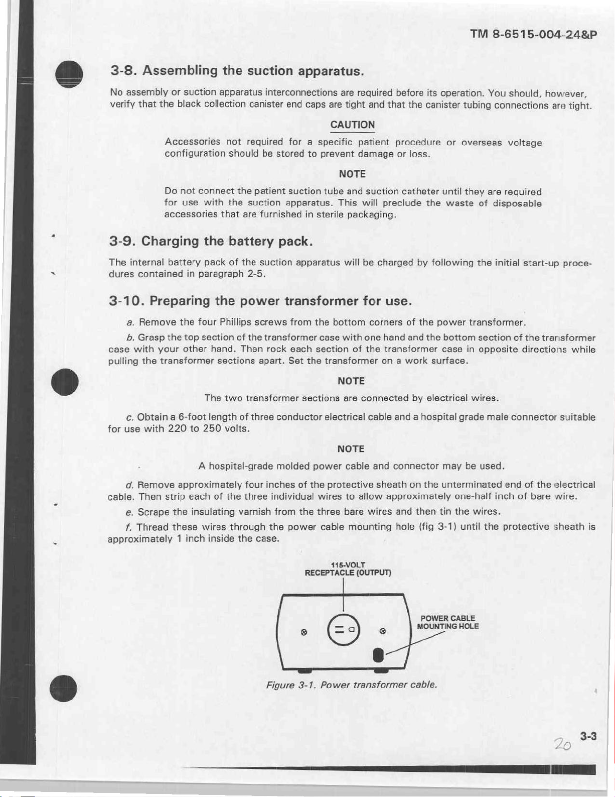
f.
Thread
Then
approximately
strip
each
the
insulating
these
The
two
transformer
length
250
wires
inside
of
three
volts.
hospital-grade
four
of
the
three
varnish
through
the
sections
conductor
molded
inches
individual
from
the
case.
power
electrical
power
of
the
wires
the
three
cable
RECEPTACLE
NOTE
are
connected
cable and a hospital
NOTE
cable
protective
to
allow
bare
wires
mounting
115-VOLT
(OUTPUT)
by
and
connector
sheath
on
approximately
and
hole
electrical
may
the
unterminated
then
tin
(fig
3-1)
POWER
MOUNTING
wires.
grade
be
one-half
the
wires.
until
CABLE
HOLE
male
used.
inch
the
connector
end
of
the
of
bare
protective
suitable
electrical
wire.
sheath
is
Figure
3-1.
Power
transformer
cable.
TM
8-6515-004-24&P
g.
hole
Install
until
р.
Connect
Pin
it
the
locks
power
into
the
electrical
Description
cable
place.
strain
wires
relief
to
the
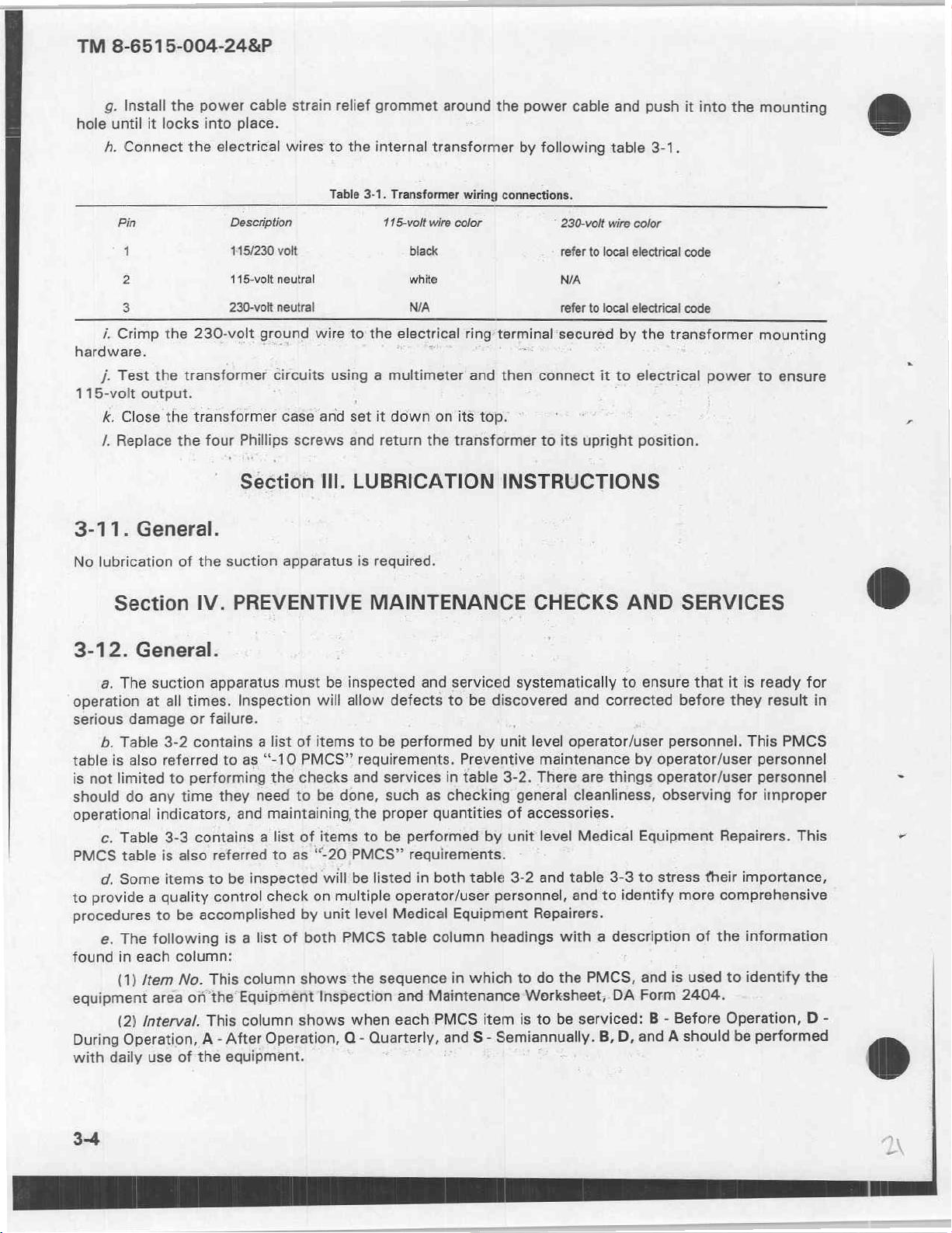
Table
grommet
internal
3-1.
Transformer
115-volt
around
transformer
wire
the
wiring
color
power
by
following
connections.
230-volt
cable
and
table
wire
color
push
3-1.
it
into
the
mounting
1
2
i.
3
Crimp
the
hardware.
j.
Test
the
115-volt
3-11.
No
output.
k.
Close
the
/.
Replace
General.
lubrication
Section
3-12.
operation
serious
table
is
should
operational
PMCS
to
procedures
found
equipment
During
with
General.
a.
The suction
at
damage
b.
Table
3-2
is
also
referred
not
limited
do
any
indicators,
c.
Table
3-3
table
is
d.
Some
items
provide a quality
to
e.
The
following
in
each
(1)
/tem
area
Interval.
(2)
Operation,
daily
use
115/230
115-volt
230-volt
230-volt
transformer
transformer
the
four
of
the
suction
IV.
PREVENTIVE
apparatus
all
times.
or
failure.
contains a list
to
to
performing
time
they
contains a list
also
referred
to
be
control
be
accomplished
is a list
column:
No.
This
the
on
This
After
-
A
of
the
equipment.
volt
neutral
neutral
ground
circuits
case
Phillips
screws
Section
apparatus
must
Inspection
of
as
“-10
PMCS”
the
checks
need
to
and
maintaining,
of
to
as
inspected
check
by
of
column
Equipment
column
shows
shows
Operation,
wire
to
the
electrical
using a multimeter
and
set
it
down
and
return
Ill.
LUBRICATION
is
required.
MAINTENANCE
be
inspected
will
allow
defects
items
to
be
requirements.
and
services
be
done,
such
the
proper
items
to
be
‘“-20
PMCS”
will
be
listed
on
multiple
unit
both
PMCS
Inspection
Q
operator/user
level
Medical
table
the
sequence
each
when
Quarterly,
-
and
black
white
NA
ring
and
on
its
the
transformer
and
serviced
to
be
performed
Preventive
in
table
as
checking
quantities
performed
requirements.
in
both
table
Equipment
column
in
which
Maintenance
PMCS
S
and
refer
NIA
refer
terminal
then
top.
secured
connect
to
its
INSTRUCTIONS
CHECKS
systematically
discovered
by unit
3-2.
general
of
by
unit
3-2
personnel,
headings
to
Worksheet,
is
item
Semiannually.
-
and
level
operator/user
maintenance
There
cleanliness,
accessories.
level
and
table
and
Repairers.
with a description
do
the
be
to
to
local
electrical
to
local
electrical
by
it
to
upright
AND
to
corrected
are
things
Medical
3-3
to
identify
PMCS,
DA
serviced:
D,
B,
code
code
the
transformer
electrical
position.
SERVICES
ensure
by
Equipment
to
and
Form
and
that
before
personnel.
operator/user
operator/user
observing
stress
more
of
is
used
2404.
Before
-
B
should
А
mounting
power
their
to
it
is
ready
they
result
This
personnel
personnel
for
improper
Repairers.
importance,
comprehensive
the
information
to
identify
Operation,
performed
be
ensure
for
in
PMCS
This
the
D
-
3-4
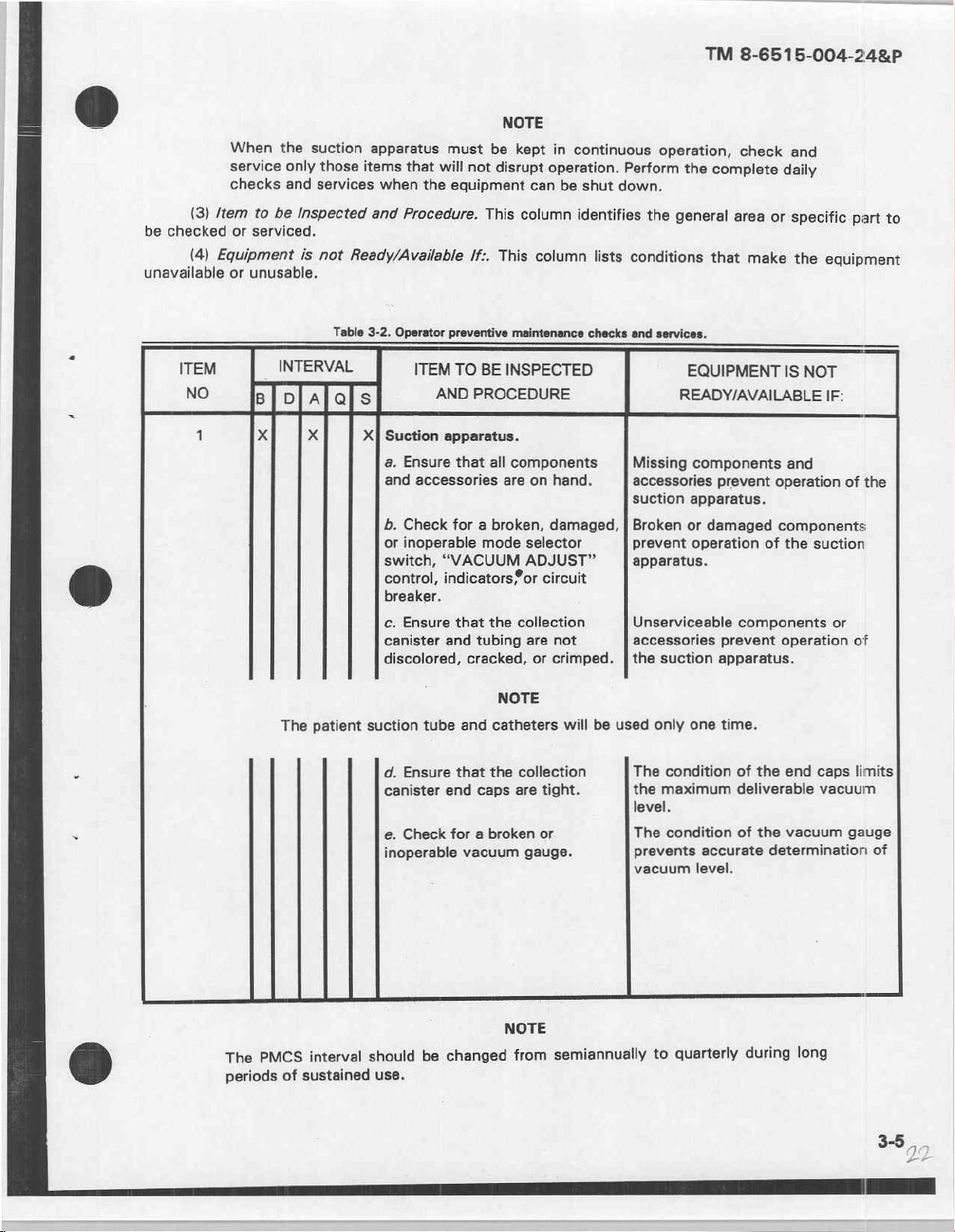
TM
8-6515-004-24&P
a
(3)
/tem
checked
be
(4)
Equipment
unavailable
ITEM
NO
1
When
service
checks
to
be
serviced,
or
unusable.
or
в] в да
x
the
suction
only
those
services
and
Inspected
is
not
Table
INTERVAL
x
apparatus
items
when
and
Ready/Available
3-2.
Operator
X]
Suction
a.
and
b.
or
switch,
control,
breaker.
c.
canister
discolored,
must
that
will
equipment
the
Procedure.
preventive
ITEM
TO
AND
apparatus.
Ensure
Check
inoperable
Ensure
that
accessories
for a broken,
“VACUUM
indicators®or
that
and
NOTE
be
kept
in
not
disrupt
This
/f:.
This
BE
PROCEDURE
all
mode
the
tubing
cracked,
operation.
can
column
column
maintenance
INSPECTED
components
are
on
hand.
damaged, | Broken
selector
ADJUST”
circuit
collection
are
not
or
crimped. | the
continuous
shut
be
identifies
lists
checks
operation,
Perform
down.
conditions
and
Missing
accessories
suction
prevent
apparatus.
Unserviceable
accessories
the
the
general
services.
READY/AVAILABLE
suction
check
complete
area
that
make
EQUIPMENT
components
prevent
apparatus.
or
damaged
operation
components
prevent
apparatus.
and
daily
or
specific
the
equipment
IS
NOT
IF:
and
operation
components
of
the
suction
operation
or
part
of
of
to
the
@
=
-
The
PMCS
The
periods
of
patient
interval
sustained
suction
should
use.
tube
d.
Ensure
canister
Check
e.
inoperable
be
and
that
the
end
caps
broken
a
for
vacuum
changed
NOTE
catheters
collection
are
tight.
or
gauge.
NOTE
from
will
be
used
The
the
semiannually
only
condition
maximum
level.
condition
The
prevents
vacuum
quarterly
to
one
time.
accurate
level.
of
the
end
deliverable
vacuum
the
of
determination
during
long
caps
vacuum
gauge
limits
of
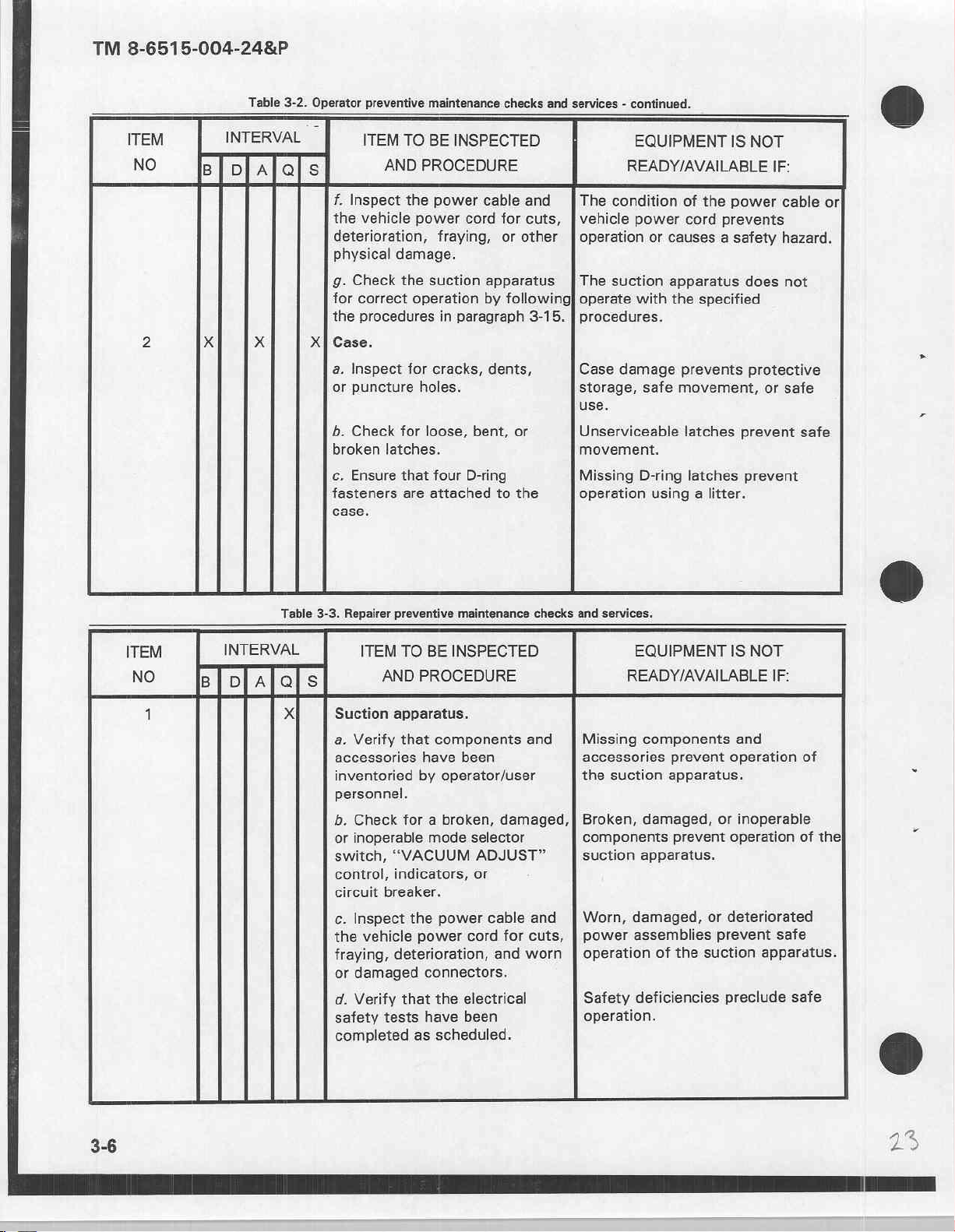
TM
8-6515-004-24&P
ITEM
NO
2
Table
INTERVAL
Biplalols
x x
3-2.
Operator
X|
preventive
ITEM
f.
Inspect
the
vehicle
deterioration,
physical
9.
Check
for
correct
the
procedures
Case.
a.
Inspect
or
puncture
b.
Check
broken
c.
Ensure
fasteners
case.
maintenance
TO
BE
AND
PROCEDURE
the
power
power
fraying,
damage.
the
suction
operation
for
cracks,
holes.
for
loose,
latches.
that
four
are
attached
checks
and
INSPECTED
cable and
cord
for
cuts, | vehicle
or
other | operation
apparatus | The suction
by
following]
in
paragraph
bent,
D-ring
3-15. | procedures.
dents,
or
to
the
services - continued.
EQUIPMENT
READY/AVAILABLE
The
condition
power
operate
Case
storage,
use.
Unserviceable
movement.
Missing
operation
with
damage
of
cord
or
causes a safety
apparatus
the
prevents
safe
movement,
latches
D-ring
using a litter.
IS
the
power
prevents
specified
latches
NOT
IF:
cable
hazard.
does
not
protective
or
safe
prevent
prevent
or
safe
Table
3-3.
ITEM
NO
1
INTERVAL
Bilolalals
X
Repairer
Suction
a.
accessories
inventoried
personnel.
b.
or
switch,
control,
circuit
c.
the
fraying,
or
d.
safety
completed
preventive
ITEM
TO
AND
apparatus.
Verify
that
Check
inoperable
Inspect
damaged
Verify
for a broken,
“VACUUM
indicators,
breaker.
the
vehicle
power
deterioration,
that
tests
as
maintenance
BE
INSPECTED
PROCEDURE
components
have been
by
operator/user
mode
selector
ADJUST”
or
power
cord
connectors.
the
electrical
have
been
scheduled.
checks
and
damaged,
cable and
for
cuts,
and
worn
and
services.
EQUIPMENT
READY/AVAILABLE
Missing
accessories
the
suction
Broken,
components
suction
Worn,
power
operation
Safety
operation.
damaged,
apparatus.
damaged,
assemblies
deficiencies
components
prevent
apparatus.
prevent
of
the
suction
IS
NOT
and
operation
or
inoperable
operation
or
deteriorated
prevent
apparatus.
preclude
IF:
safe
of
of
safe
the
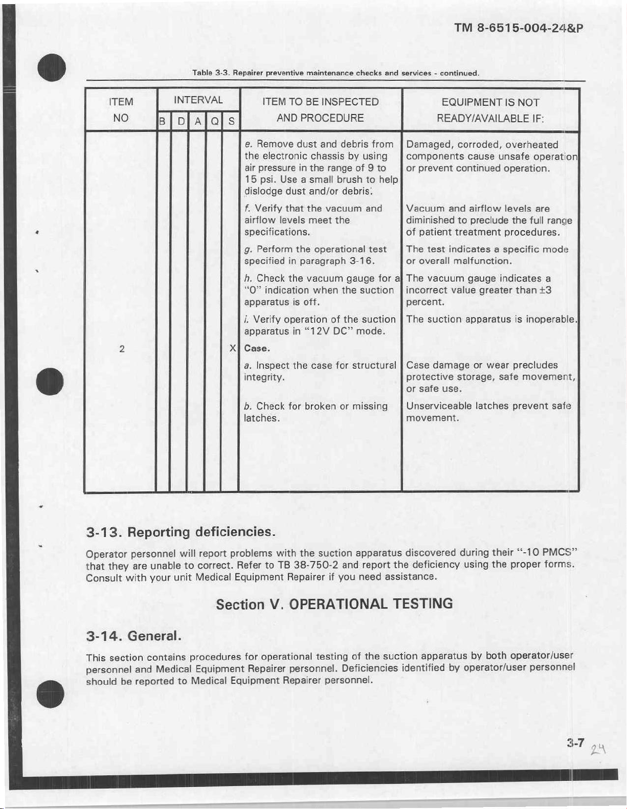
TM
8-6515-004-24&P
Table
3-3.
Repairer
ITEM
NO
preventive
ITEM TO
e.
Remove
the
electronic
air
pressure
15
psi.
dislodge
f.
Verify
airflow
specifications.
g.
Perform
specified
h.
Check
“0”
indication
apparatus
i.
Verify
apparatus
Case.
a.
Inspect
integrity.
b.
Check
latches.
maintenance
BE
AND
PROCEDURE
dust
in
the
Use a small
dust
and/or
that
the
levels
meet
the
in
paragraph
the
vacuum
is
off.
operation
in
“12V
the
for
broken
INSPECTED
and
debris
chassis
operational
when
case
by
range
brush
debris:
vacuum
the
gauge
the
of
the
DC"
for
or
3-16.
structural
missing
checks
from
using
of 9 to
to
help
and
test
for
suction
suction
mode.
and
services - continued.
EQUIPMENT
READY/AVAILABLE
Damaged,
components
or
prevent
Vacuum
diminished
of
patient
The
test
or
overall
al
The
vacuum
incorrect
percent.
The suction
Case
damage
protective
or
safe
use.
Unserviceable
movement.
IS
NOT
IF:
corroded,
cause
continued
and
airflow
to
preclude
treatment
indicates a specific
malfunction.
gauge
value
apparatus
or
storage,
unsafe
indicates
greater
wear
safe
latches
overheated
operation.
levels
the
full
procedures.
than
is
inoperable.
precludes
movement,
prevent
operation]
are
range
mode
a
+3
safe
3-13.
Operator
that
Consult
3-14.
This
personnel
should
Reporting
personnel
are
they
with
General.
section
and
be
reported
unable
your
unit
contains
Medical
deficiencies.
will
report
correct.
to
Medical
procedures
Equipment
to
Medical
problems
Refer
Equipment
Section
for
Equipment
with
TB
to
V.
operational
Repairer
Repairer
OPERATIONAL
personnel.
Repairer
the
suction
38-750-2
testing
personnel.
apparatus
report
and
if
you
need
the
of
Deficiencies
discovered
deficiency
the
assistance.
TESTING
suction
apparatus
identified
during
by
their
“-10
proper
the
using
operator/user
both
by
operator/user
PMCS”
forms.
personnel
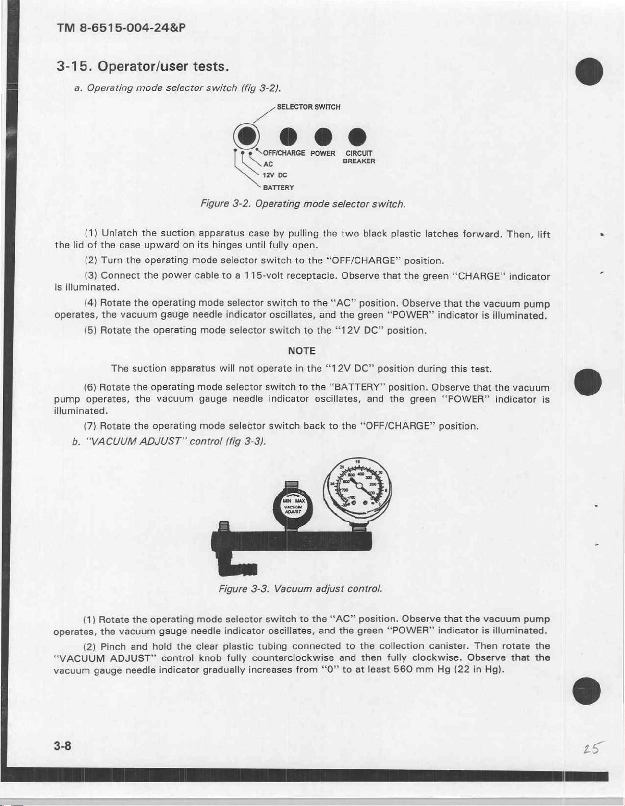
TM
8-6515-004-24&P
3-15.
the
is
illuminated.
operates,
Operator/user
a.
Operating
(1)
lid
of
the
(2)
Turn
(3)
(4)
Rotate
(5)
Rotate
Unlatch
case
the
Connect
the
vacuum
mode
the
suction
upward
operating
the
the
operating
gauge
the
operating
tests.
selector
on
mode
power
cable
needle
switch
Figure
apparatus
its
mode
mode
3-2.
hinges
selector
to a 115-volt
selector
indicator
selector
(fig
3-2).
Da
$ $ SOFFICHARGE
©
SELECTOR
AC
12v
DC
BATTERY
Operating
case
until fully
switch
switch
oscillates,
switch
mode
by
pulling
open.
to
receptacle.
to
to
NOTE
SWITCH
POWER
selector
the
two
the
“OFF/CHARGE”
Observe
the
“AC”
and
the
the
“12V
CIRCUIT
BREAKER
switch.
black
position.
green
DC”
plastic
position.
that
the
Observe
“POWER”
position.
latches
green
that
indicator
forward.
“CHARGE”
the
vacuum
is
Then,
illuminated.
lift
indicator
pump
dG
.
(6)
Rotate
pump
operates,
illuminated.
(7)
Rotate
b.
“VACUUM
(1)
Rotate
operates,
“VACUUM
vacuum
(2)
the
Pinch
ADJUST”
gauge
The
vacuum
needle
suction
the
operating
the
vacuum
the
operating
ADJUST”
the
operating
and
hold
apparatus
control
gauge
indicator
needle
the
control
will
mode
selector
gauge
mode
(fig
Figure
mode
selector
indicator
clear
plastic
knob
gradually
not
operate
switch
needle
selector
indicator
switch
3-3).
3-3.
switch
oscillates,
tubing
fully
counterclockwise
increases
in
Vacuum
connected
from
the
“12V
to
the
“BATTERY”
oscillates,
back
to
adjust
to
the
and
“O”
the
“AC”
the
to
and
to
DC”
position
and
“OFF/CHARGE”
control.
position.
green
the
collection
then
at
least
during
position.
the
green
Observe
“POWER?”
fully
clockwise.
560
mm
this
Observe
“POWER?”
position.
that
the
indicator
canister.
Hg
(22
test.
that
the
indicator
vacuum
is
illuminated.
Then
Observe
in
Hg).
vacuum
pump
rotate
that
@
is
the
the
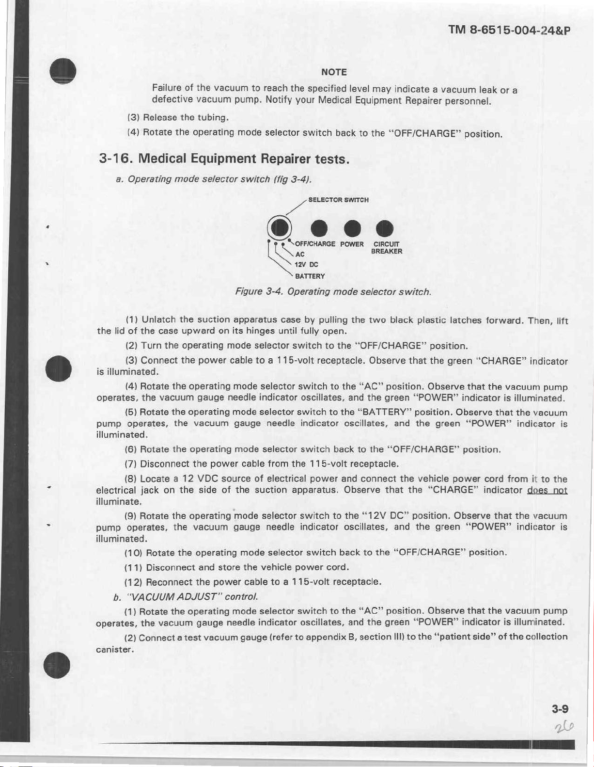
(3)
Release
(4)
Rotate
Failure
defective
of
the
the
the
vacuum
vacuum
tubing.
operating
to
pump.
mode
reach
the
Notify
selector
specified
your
Medical
switch
NOTE
back
level
may
Equipment
to
the
indicate
“OFF/CHARGE”
a
Repairer
TM
8-6515-004-24&P
vacuum
personnel.
position.
leak
or
a
3-16.
the
is
illuminated.
operates,
pump
Medical
a.
Operating
(1)
lid
of
(2)
(3)
(4)
(5)
operates,
Unlatch
the
Turn
Connect
Rotate
the
Rotate
illuminated.
(6)
Rotate
(7)
Disconnect
(8)
Locate a 12
electrical
jack
illuminate.
(9)
Rotate
pump
operates,
illuminated.
(10)
Rotate
(11)
Disconnect
(12)
Reconnect
b.
“VACUUM
(1)
Rotate
operates,
(2)
the
Connect
canister.
mode
the
case
the
the
the
vacuum
the
the
the
on
the
the
the
the
ADJUST”
the
vacuum
a
Equipment
selector
suction
upward
operating
operating
operating
test
on
power
operating
gauge
vacuum
operating
the
power
VDC
source
side
of
operating
vacuum
operating
and
store
the
power
gauge
vacuum
switch
Figure
apparatus
its
hinges
mode
selector
cable
to a 115-volt
mode
selector
needle
mode
gauge
mode
indicator
selector
cable
of
the
suction
mode
gauge
mode
the
vehicle
cable
control.
mode
selector
needle
indicator
gauge
Repairer
(fig
3-4).
>
“SOFFICHARGE
US
AC
12V
BATTERY
3-4.
Operating
case
by
until
fully
switch
switch
oscillates,
switch
needle
selector
from
electrical
selector
needle
selector
to a 115-volt
(refer
indicator
switch
the
apparatus.
switch
indicator
power
switch
oscillates,
to
tests.
SELECTOR
pc
mode
pulling
open.
to
the
receptacle.
to
to
back
115-volt
power
to
switch
appendix
back
cord.
receptacle.
to
SWITCH
POWER
the
the
oscillates,
CIRCUIT
BREAKER
selector
the
two
“OFF/CHARGE”
Observe
“AC”
and
the
“BATTERY”
to
the
receptacle.
and
connect
Observe
the
““12V
oscillates,
to
the
the
“AC”
and
the
section
B,
switch.
black
plastic
position.
that
the
position.
green
Observe
“POWER”
position.
and
the
“OFF/CHARGE”
the
vehicle
that
the
“CHARGE”
DC”
position,
and
the
“OFF/CHARGE”
position.
green
Ill)
Observe
“POWER”
the
to
latches
green
indicator
Observe
green
position.
power
Observe
green
indicator
“patient
forward.
“CHARGE”
that
the
that
“POWER”
cord
indicator
that
“POWER”
position.
that
the
of
side”
Then,
indicator
vacuum
is
illuminated.
the
vacuum
indicator
from
it
to
does
the
vacuum
indicator
vacuum
is
illuminated.
collection
the
lift
pump
is
the
not
is
pump
3-9
 Loading...