

HEADQUARTERS DEPARTMENT OF THE ARMY 306M User manual
TM
8-6515-013-14&P
TECHNICAL
OPERATOR,
GENERAL
SUPPORT
UNIT,
(INCLUDING
SPECIAL
SUCTION
PROGRAMMABLE
SUCTION-ASPIRATOR
MANUAL
DIRECT
SUPPORT,
MAINTENANCE
REPAIR
TOOLS
PARTS
LIST)
APPARATUS
INTERMITTENT
AND
MANUAL
AND
SYSTEM
APPROVED
HEADQUARTERS,
FOR
MODEL
6515-01-267-2726
PUBLIC
RELEASE;
DEPARTMENT
306M
DISTRIBUTION
OF
IS
UNLIMITED
THE
ARMY
May
1999
SAFETY
STEPS
TO
FOLLOW
IF
SOMEONE
IS
THE
VICTIM
OF
ELECTRICAL
SHOCK
Do
not
try
to
possible,
If
you
If
person
insulating
cannot
safety
to
material.
pull
turn
or
off
turn
off
using
grab
the
the
electrical
electrical
the
wooden
dry
a
individual.
power.
power,
pole
ora
pull,
push,
dry
rope,
or
or
the
lift
some
other
-
help
Send
After
shock,
artificial
for
injured
the
move
resuscitation.
soon
as
person
the
as
person
possible.
contact
free
is
short
a
of
distance
with
away
source
the
and
electrical
of
immediately
start
TM
8-6515-013-14&P
Throughout
to
read
these.
Procedures
this
manual
They
are
which
are
WARNINGS,
there
must
be
to
protect
you
WARNING
observed
to
CAUTIONS,
and
the
avoid
personal
and
NOTES.
equipment.
injury,
and
even
Please
loss
of
take
life.
time
Procedures
which
must
be
Essential
observed
long-term
information
to
avoid
damage
health
that
should
to
equipment,
hazards.
be
remembered.
destruction
of
equipment,
or
8/0
blank
TM
8-6515-013-14&P
TECHNICAL
8-6515-013-148P
NO.
You
cedures,
to
Publications
Technical
Agency,
reply
MANUAL
OPERATOR,
(INCLUDING
SUCTION
SUCTION-ASPIRATOR
can
help
improve
1423
will
please
be
let
and
Publications)
Sultan
furnished
UNIT,
SUPPORT
REPAIR
APPARATUS
this
manual.
us
know.
Mail
Blank
Forms),
located
Drive,
directly
in
Suite
to
you.
DIRECT
SUPPORT,
MAINTENANCE
PARTS
AND
SPECIAL
PROGRAMMABLE
SYSTEM,
6515-01-267-2726
If
you
find
any
mistakes
your
memorandum,
or
DA
the
back
100,
ATTN:
Form
of
2028-2
this
MCMR-MMM,
DA
(Recommended
manual
WASHINGTON,
MANUAL
MODEL
or
if
you
Form
2028
to:
U.S.
Fort
HEADQUARTERS
DEPARTMENT
DC
AND
GENERAL
TOOLS
INTERMITTENT
306M
know a way
(Recommended
Changes
Army
Medical
Detrick,
MD
to
to
Materiel
21702-5001.
OF
THE
LIST)
improve
Changes
Equipment
ARMY
pro-
A
CHAPTER
Section
CHAPTER
Section
1.
I.
Il
Ill
2.
1.
|.
Ill.
IV.
V.
VI.
Approved
ROWTEOUSETHIS
INTRODUCTION
General
Equipment
Principles
OPERATING
Preparation
Operating
Operating
Operation
Cleaning,
Operation
Information
Description
of
Operation
for
Information
Instructions . .
of
Auxiliary
Disinfecting,
Under
for
public
TABLE
MANUAE
and
INFORMATION
Operations
..
Equipment
and
Unusual
release;
OF
Data
Sterilizing
Conditions
distribution
CONTENTS
o
iui
.
AND
INSTRUCTIONS
casinos
36
is
unlimited.
dask
SEER
Procedures
.....................................
e
nee
amer
k
τος.
iv
2-1
2-8
TM
8-6515-013-14&P
CHAPTER
3.
UNIT
LEVEL
MAINTENANCE
Section
CHAPTER
Section
APPENDIX
GLOSSARY
INDEX
|.
Il
Ill
IV.
V.
VI.
VII.
Vill.
IX.
4.
L
Generalilnformationi
Service
Lubrication
Preventive
Operational
Troubleshooting....
Circuit
Repair
Storing
DIRECT
人
Maintenancs
還
MAINTENANCE
COMPONENTS
EXPENDABLE
REPAIR
Riano
Upon
Receipt
Instructions..
Maintenance
Testing.
Descriptions
Procedures.........
and
Shipping
SUPPORT
IR
..................
.
AND
rocaduros
ALLOCATION
OF
END
AND
DURABLE
PARTS
AND SPECIAL
LIST
ec
ον
of
Equipment
Checks
Procedures
GENERAL
TE
CHART
ITEM
AND
SUPPLIES
OF
ILLUSTRATIONS
on
.
and
Si
.....:.................................
SUPPORT
earn
ος
περ.
MAINTENANCE
«τοσα...
J E
et
.....................
BASIC ISSUE
TOOLS
AND
LIST
aan
ITEMS
MATERIALS
LIST
LIST
ein
....
..
.
GLOSSARY-1
net
3-1
„3-2
.
3-2
3-24
4-1
4-1
A-1
.
B-1
INDEX-1
Figure
1-1
1-2
3
1-4
1-5
2-1
2-2
2-3
2-4
3-1
3-2
3-3
3-4
E-1
E-2
E-3
E-4
E-5
E-6
E-7
No.
Suction
Components
Manufacturer
Front
(Gartassemblyi
Hose
Front
Rear
Control
Power
Suction
On/off
Suction
Front
Rear
Chassis
Heat
Heat
Battery
apparatus
and
data
panel
imprinting
interconnection
panel
controls
panel
controls
circuit
supply
level
and
one - shots
apparatus
panel
assembly
panel
assembly.
assembly
sink
sink
#1
#2
pack
Title
accessories
plate...
.
tal.
te
code
.
and
indicators
and
indicators
PCB
layout
and
charging
motor
speed
schematic...................
components
.......
alert
circuit
schematic
control
.
circuits
oe
Е
аа
Page
„+
1-1
Aa
в
人
ne
E-8
E-9
Pump
Left
assembly
and
right
sub-side
assemblies
LIST
OF
....
TABLES
TM
8-6515-013-14&P
.
E-24
.
Е-26
Table
1-1
1-2
1-3
3-1
3-2
3-3
3-4
No.
Nomenclature
Specifications
Miscellaneous
Operator
Repairer
preventive
preventive
Operator/user
Medical
Equipment
Title
cross-referencelist........................................
characteristics
maintenance
maintenance
troubleshooting
Repairer
checks
checks
and
and
troubleshooting
services
services.
. .
..
. .
..1
..
„34
58
..
3-10
Page
1-2
1-4
1-4
TM
8-6515-013-14&P
HOW
This
capabilities,
describes
The
followed
manual
must
beginning a maintenance
Use
general
subjects.
Multiple
manual.
components
familiarize
manual
the
table
subject
provides
functions,
how
to
set up,
yourself
is
arranged
by
appendixes, a glossary,
of
contents
area
figures
Words
or
and
that
words
TO
needed.
tables
USE
all
the
and
operate,
with
task.
to
are
both
that
you
by
THIS
information
characteristics
test,
and
the
entire
chapters,
help
locate
The
index
are
provided
capitalized
will
actually
an
manual
index,
the
will
MANUAL
needed
repair
sections,
chapter
help
for
and
see
of
and
locate
your
on
to
this
the
before
DA
ease
bold
the
understand
equipment.
equipment.
operating
and
paragraphs
Forms
or
section
more
in
using
are
names
equipment.
the
It
You
or
2028-2.
for
the
specific
this
of
Chapter 3 provides a systematic
equipment.
become a major
doing
anything
Only
allocation
specified
training;
perform
the
wrong
for
test,
In
this
way,
problem
checks
will
maintenance
chart
for
higher
measurement,
small
and
services
be
detected
level
your
levels
causing
of
method
defects
functions
of
maintenance
and
can
the
in
the
quickly.
maintenance.
diagnostic
of
inspecting
be
detected
equipment
same
specified
frequently
equipment;
and
servicing
early
to
fail.
Make a habit
order
Maintenance
the
in
require
each
maintenance
or
the
before
tools.
they
time
additional
and
functions
of
TM
8-6515-013-14&P
1-1.
Overview.
This
manual
operational
describes
and
maintenance
Section
the
suction
functions,
CHAPTER
INTRODUCTION
I.
GENERAL
apparatus
services,
(fig
and
INFORMATION
1-1);
provides
actions.
1
equipment
Additional
technical
information
data;
and
follows.
provides
a.
Type
repair
parts
b.
Model
c.
Purpose
surgery.
1-2.
Explanation
Special
or
ofmanual.
and
special
number
of
equipment.
unique
abbreviations,
Operator,
tools
and
equipment
To
of
unit,
list).
provide
Figure
direct
name.
1-1.
support
Model
continuous
abbreviations
acronyms,
and
Suction
(DS),
number
or
intermittent
and
terms
used
apparatus.
and
general
306M,
Suction
oral,
terms.
in
this
support
nasal,
manual
(GS)
maintenance
Apparatus,
and
tracheal
are
explained
Surgical.
suctioning
in
the
glossary.
(including
during
1-1
TM
8-6515-013-14&P
1-3.
Maintenance
a.
Reports
are
used
for
equipment
b.
Report
1-4.
Destruction
AR
40-61
series
publications
hazardous.
are
1-5.
Administrative
a,
Placement
shortage
hours
or
appropriate
b.
Perform
placing
to
Army
ensure
c.
Inside
of
contains
of
maintenance
within
maintenance
equipment
operational
its
storage
of
maintenance
packaging
instructions
provide
of
the
suction
the
time
preventive
is
preferred
forms,
and
unsatisfactory
maintenance.
and
handling
of
Army
for
destruction
periodic
information
storage.
apparatus
effort
exists.
factors
in
readiness.
as
determined
records.
maintenance
administrative
for
equipment
records,
deficiencies.
materiel
and
and/or
in
administrative
This
eguipment
by
checks
storage.
selected
and
reports.
equipment.
Fill
out
to
prevent
disposal
instructions
storage
should
the
directing
and
services
When
equipment
for
Department
and
forward
of
the
SF380
enemy
of
Army
medical
on
the
disposal
should
be
in
authority.
(PMCS)
administrative
mission
listed
is
removed
be
During
storage.
Army
(Report
use.
materiel.
of
for
short
readiness
the
in
tables
from
storage,
forms
and
of
Also,
medical
periods
condition
storage
3-1
and
procedures
Survey).
the
SB
materiel
oftime
perform
when
within
period,
3-2
8-75
that
a
24
keep
before
PMCS
1-6.
Preparation
Procedures
1-7.
Quality
AR
702-18/DLAR
procedures.
1-8.
Nomenclature
Table
1-1
identifies
Aspirator
1-9.
quality
AR
reports
Reporting
improvement
40-61
prescribes
for
the
to
prepare
the
control
4155.37/NAVSUPINST
official
Common
Suction
Vacuum
Collection
apparatus
adjust
suction
name
bottles
procedures
apparatus.
for
storage
suction
apparatus
(QC).
4410.56/AFR
cross-reference
versus
control
and
commonly
Table
1-1,
knob
processing
reports.
for
submitting
or
shipment.
for
storing
used
nomenclatures.
Nomenclature
medical
medical
or
shipping
69-10/MCO
list.
cross-reference
Official
Suction
Suction
Electronic
Collection
materiel
materiel
are
listed
4450.13
list.
nomenclature
apparatus,
apparatus,
complaints
contains
vacuum
canisters
in
chapter
surgical
surgical
regulator
3,
section
QC
requirements
(EVR)
complaints
and/or
quality
IX.
and
and/or
improvement
1-10.
A
warranty
1-2
Warranty
is
not
applicable.
information.
TM
8-6515-013-14&P
1-11.
mable
accumulated
empty
below
external
(0-8
of
the
hold the
4-12.
chassis
printed
operational
cal
control
ceptacle
porates
dual
collection
liquid,
The
nation
phobic,
maximum
fluids.
tains
length,
tubing
control.
connect
Equipment
a.
The
suction
intermittent
from
the
the
suction
b.
The
suction
115/220
c.
The
suction
in
Hg)
LOW
being
user
d.
The
unitis
same
time
e.
The
suction
unit.
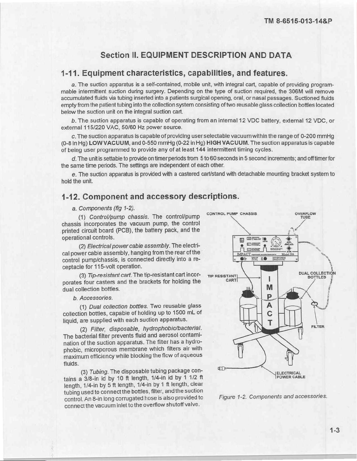
Component
a.
Components
(1)
Control/pump
incorporates
circuit
(2)
Electrical
power
cable
pump/chassis,
for
Tip-resistant
(3)
four
collection
b.
Accessories.
Dual
(1)
bottles,
supplied
are
(2)
bacterial
the
of
microporous
Tubing.
(3)
3/8-in
a
1/4-in
used
An
the
Filter,
efficiency
Section
apparatus
suction
fluids
via
patient
unit
apparatus
VAC,
apparatus
VACUUM,
programmed
settable
periods.
apparatus
(fig
board
(PCB),
controls.
power
assembly,
115-volt
casters
bottles.
collection
capable
with
disposable,
prevents
filter
suction
while
The
by
id
ft
5
by
connectthe
to
corrugated
long
8-in
vacuum
inlet
Il.
EQUIPMENT
characteristics,
is a self-contained,
during
tubing
tubing
on
the
50/60
to
The
1-2).
chassis.
the
connected
is
operation.
cart.
and
each
apparatus.
membrane
disposable
ft
10
length,
to
surgery.
inserted
into
integral
is
is
and
to
provide
settings
is
and
vacuum
the
cable
hanging
The
the
bottles.
of
fluid
blocking
length,
1/4-in by
bottles,
the
into a patients
the
collection
suction
capable
Hz
power
capable
0-550
provide any
provided
of
source.
of
mmHg
on
timer
are
independent
with a castered
accessory
The
control/pump
pump,
battery
assembly.
tip-resistant
brackets
holding
suction
hydrophobic/bacterial.
The
hose
overflow
from
directly
Two
up
apparatus.
aerosol
and
filter
which
flow
the
tubing
1/4-in
1
filter,
is
pack,
the
for
reusable
to
filters
ft
andthe
also
shutoff
DESCRIPTION
capabilities,
mobile
Depending
surgical
system
cart.
operating
providing
of
periods
the
The
holding
1500
has
of
package
id
length,
user
(0-22
in
at
least
from 5 to
of
descriptions.
control
and
the
electri-
of
rear
a
into
cartincor
glass
mL
contami-
hydro-
a
with
air
aqueous
con-
1/2
1
by
clear
suction
provided
valve.
unit,
with
on
the
type
opening,
consisting
from
an internal
selectable
Hg)
HIGH
144
intermittent
60
each
other.
cart/stand
CONTROL
the
re-
ResisTANTI
TiP
。
the
of
ft
to
AND
and
integral
of
of
two
VACUUM.
seconds
with
PUMP
CART
cart,
suction
oral,
or
reusable
12
VDC
vacuum
within
The
timing
in 5 second
detachable
CHASSIS
Components
Figure
1-2.
DATA
features.
capable
required,
nasal
glass
battery,
suction
cycles.
Nereo
of
the
passages.
collection
external
the
range
apparatus
increments;
mounting
POWER
and
providing
306M
bracket
program-
will
Suctioned
bottles
12
of
0-200
is
and
off
system
OVERFLOW
TUBE
QJ
FILTER
CABLE
accessories.
remove
fluids
located
VDC,
or
mmHg
capable
timer
for
to
TM
8-6515-013-14&P
1-13.
The tabulated
suction
miscellaneous
operating/storing
Tabulated
data
apparatus.
a.
Specifications
characteristics
temperature
Voltage/frequencies
Internal
Vacuum
power..
Operating
Recharge
ranges
provides
time
Continuous
Low
High
Intermittent
Free
airflow
range
Dimensions
data,
and
miscellaneous
time
.
-
decals
and
miscellaneous
characteristics.
and
specifications
ranges,
dimensions,
Table
Table
1-3.
data
characteristics,
plates.
specifications,
Table
to
include
and
1-2.
Specifications.
..115
230
12
VDC
2
VDC,
hour
-16
hours
0-200
-550
-200
4-35
Miscellaneous
operating
weights.
VAC,
50/60
VAC,
50/60
recharge
at
maximum
mmHg, + 25
mmHg, + 50
mmHg, + 25
liters
per
characteristics.
1-2
and
Hz
Hz
batteries
vacuum
mmHg
mmHg
mmHg
minute
and
other
table
1-3
voltages,
information
provide a broad
vacuum
ranges,
for
the
range
flow
of
rates,
b.
in
figure
notices
Weight.
Collection
Free
Duty
Operating
Battery
Apparatus
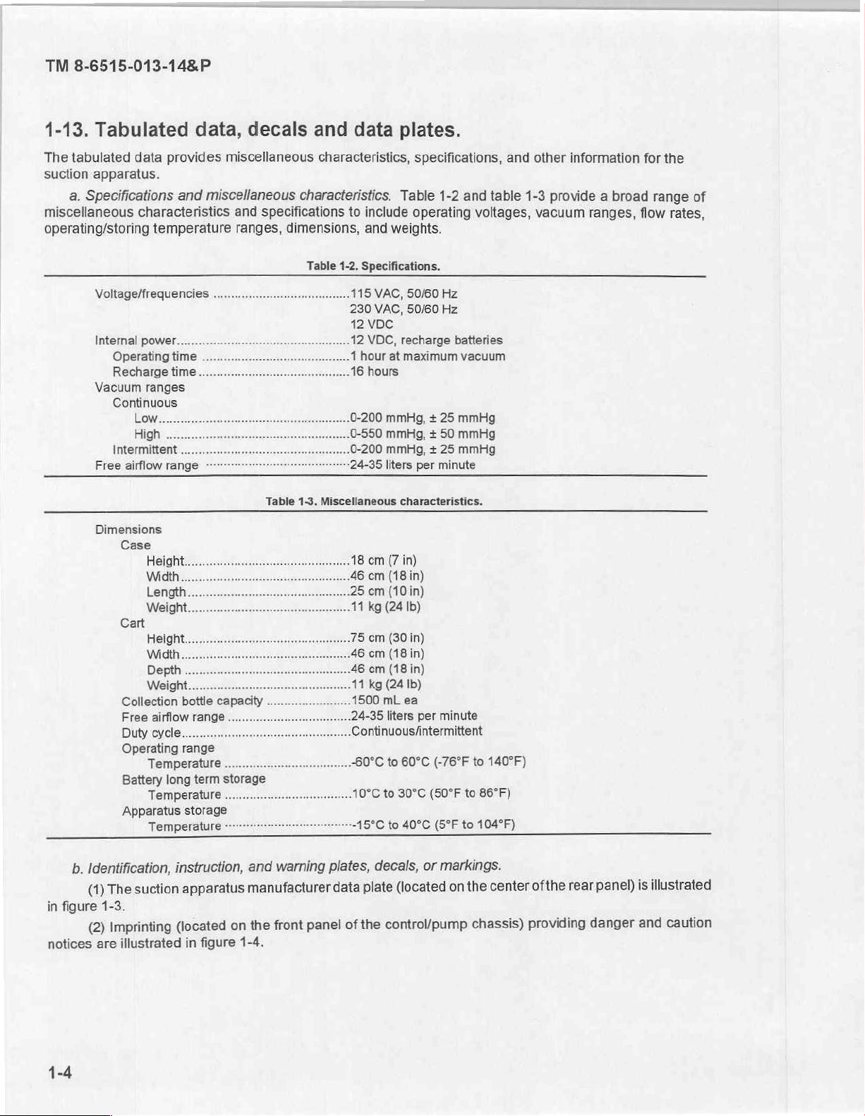
Identification,
suction
The
(1)
1-3.
Imprinting
(2)
are
illustrated
bottle
airflow
cycle...
range
Temperature
long
Temperature
storage
Temperature
instruction,
apparatus
(located
in
capacity
range
.
term
storage
figure
..
warning
and
manufacturer
front
the
on
1-4.
plates,
data
panel
8
cm
(7
in)
24-35
liters
per
minute
Continuous/intermittent
...-60°C
...10°C
+1
of
to
60°C
to
30°C
5°C
to
40°C
decals,
(located
plate
control/pump
the
(-76°F
(50°F
(5°F
markings.
or
on
to
140°F)
to
86°F)
to
104°F)
center
the
chassis)
rear
ofthe
providing
panel)
danger
illustrated
is
caution
and
CONTRACT:
IMPACT
SUCTION
APPARATUS,
115/230VAC,
DES.
ACT.
PART
NSN:
NO.
6515-01-267-2727
SER.
NO.
DLA120-88-C-8510
INSTRUMENTATION,
SURGICAL,
50/60
HZ;
12
VDC
89875
DPSC-DEPMEDS-AT/224(DM)
INC.
MODEL
10A,
FSCM:
MFD:2088
TM
306M
120W
63346
8-6515-013-14&P
1-14.
Model
differences
1-15.
a.
Observe
b.
Read
Medical
c.
Install
d.
The
pump.
e.
Operator/user
f.
There
Replace
with
!
same
二
Model
Safety,
each
the
operating
Equipment
the
bacteria
use
of a collection
is
possible
Figure
only
fuse
of
rating.
一
一
一
differences.
are not
care,
applicable
and
WARNING,
instructions
Repairer
filter
personnel
explosion
handling.
CAUTION,
personnel.
carefully
bottle
will
hazard
一
Figure
since
in
this
to
without
not
remove
if
1-3.
Manufacturer
一
1-4.
Front
this
manual
and
manual
prevent
an
overflow
the
used
in
US
Do
covers,
qualified
一
一
panel
covers a single
NOTE
in
before
damage
shutoff
instrument
the
presence
data
plate.
not
remove
Refer
personnel
一
一
imprinting.
this
manual.
operating
to
the
filter
valve
covers.
of
flammable
equipment
servicing
一
一
model.
the
unit.
Refer
and
hoses.
may
cause
There
is a danger
anesthetics.
to
only.
一
servicing
damage
|
|
一
一
to
of
electric
to
qualified
the
vacuum
shock.
1-16.
a.
The
b.
When
on)
is
controlled
c.
When
motor
but
General
vacuum
unit
is
by the
INTERMITTENT
the
control
Section
description
is
generated
tumed
motor
and
by a vane-type
on
and
speed
operation
relay
circuits
III.
PRINCIPLES
(fig
CONTINUOUS
control.
is
selected,
control
1-5).
vacuum
operation
the
amount
the
OF
pump,
is
selected,
motor
of
time
OPERATION
which
is
attached
the
motor speed
speed
the
control
motor
still
is
on
to
an
electric
(variable
controls
and
off.
the
motor.
vacuum
speed
of
is
the
TM
8-6515-013-14&P
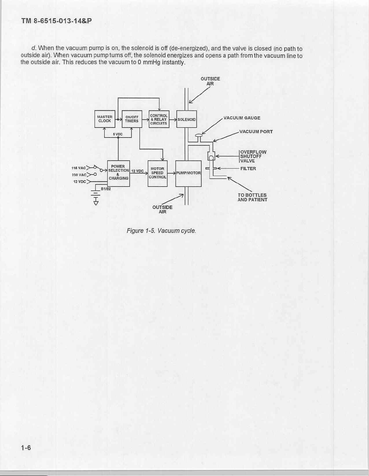
d.
When
the
outside
the
air).
outside
When
air.
vacuum
vacuum
This
pump
pump
reduces
the
is
on,
turns
vacuum
the
solenoid
off,
to 0 mmHg
the
solenoid
is
off
(de-energized),
energizes
instantly.
and
and
opens a path
OUTSIDE
AIR
the
valve
from
is
closed
the
(no
vacuum
path
line
to
to
230
Vac>—0
12000
master | [J owore
ο
8182
=>
3
ewe
POWER
a
&
CHARGING
Figure
CONTROL
|)
和
CIRCUI
[CONTROL
OUTSIDE
1-5.
Vacuum
|
AIR
soon
cycle.
VACUUM
GAUGE
VACUUM
OVERFLOW
VALVE
PORT
ое
TER
TO
BOTTLES
AND
PATIENT
TM
8-6515-013-14&P
OPERATING
2-1.
Scope.
This
manual
the
suction
mation
suctioning
2-2.
a.
erating
is
apparatus.
for
use
techniques
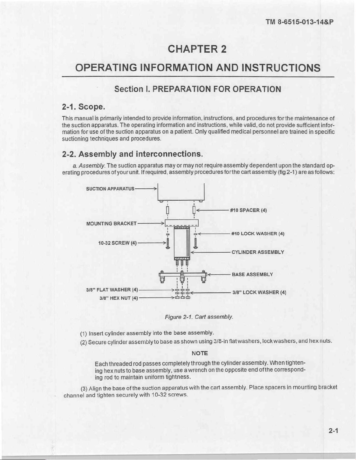
Assembly
Assembly.
procedures
Section
primarily
The
of
the
suction
and
and
The
suction
of
your
CHAPTER
INFORMATION
|.
PREPARATION
intended
unit.
to
provide
operating
apparatus
procedures.
information,
information
on a patient.
interconnections.
apparatus
Ifrequired,
may
assembly
or
instructions,
and
instructions,
Only
may
not
require
procedures
2
AND
FOR
while
qualified
medical
assembly
forthe
INSTRUCTIONS
OPERATION
and
procedures
valid,
do
personnel
dependent
cart
assembly
not
forthe
provide
are
upon
(fig
maintenance
sufficient
trained
the
standard
2-1)
are
as
infor-
in
specific
follows:
of
op-
(1)
(2)
(3)
channel
MOUNTING
10-32
i
3/8"
FLAT
3/8”
Insert
Secure
Each
ing
ing
Align
tighten
and
BRACKET
SCREW
À
WASHER
HEX
NUT
cylinder
cylinder
threaded
hexnuts
maintain
to
rod
base
the
securely
————>|
(4)
———>
„sla
(4)
(4)
assembly
assembly
rod
base
to
the
of
with
mě
Be
————>-
Figure
into
the
base
to
passes
uniform
suction
completely
assembly,
tightness.
apparatus
10-32
Ce
lá
EEE
endian
2-1.
base
shown
as
a
use
screws.
7
中 < 一
!
| そ ーーーーーーーー
Cart
assembly.
assembly.
using
NOTE
the
the
on
cart
through
wrench
with
CYLINDER
flat
3/8-in
cylinder
opposite
the
assembly.
#10
LOCK
3/8"
LOCK
washers,
assembly.
WASHER
ASSEMBLY
WASHER
ofthe
end
Place
washers,
lock
When
correspond-
spacers
(4)
(4)
tighten-
in
hex
and
mounting
nuts.
bracket
2-1
TM
8-6515-013-14&P
(4)
Casters
Depress
red
button
b.
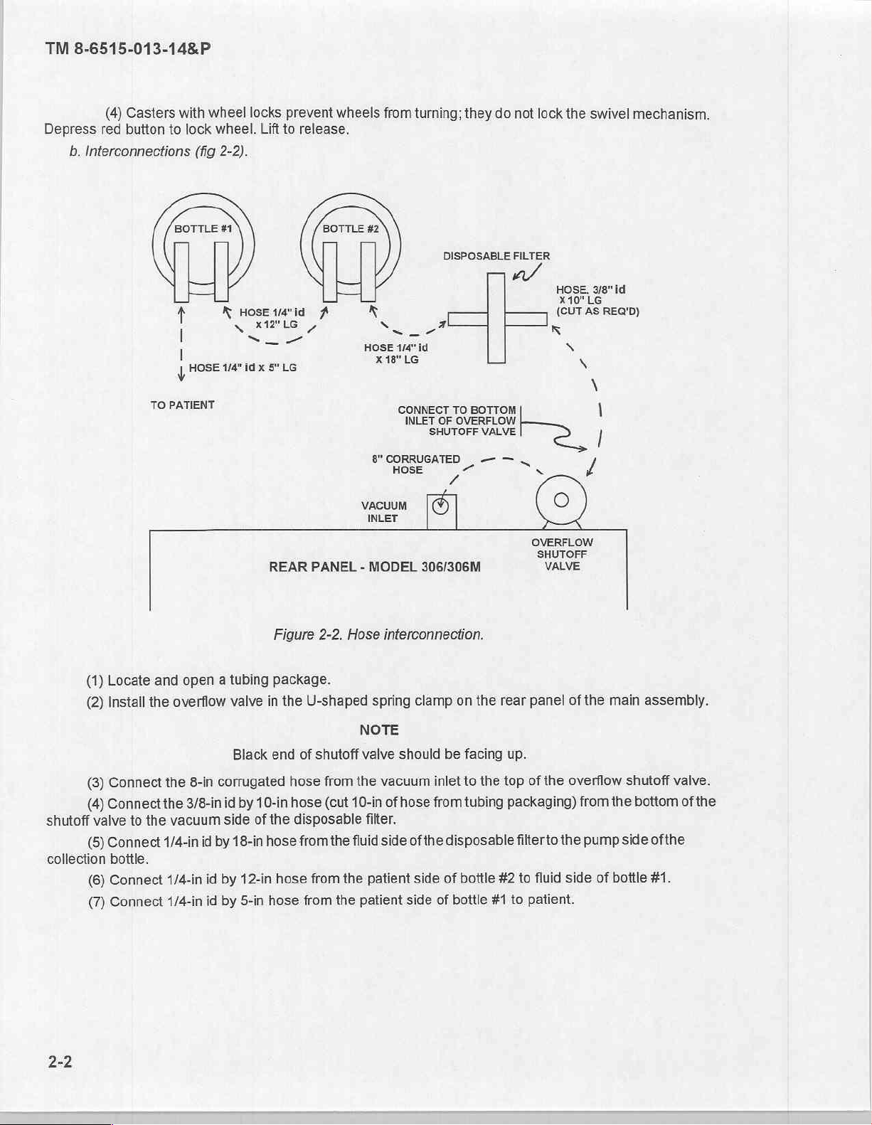
Interconnections
with
to
wheel
lock
(fig
locks
wheel.
2-2).
Lift
to
prevent
release.
wheels
from
turning;
they
do
not
lock
the
swivel
mechanism.
TO
PATIENT
(SZ
т
|
I
у
Нова
K
и"
HOSE
N
>
idx
1/4"id
x12"LG
5"LG
REAR
A
ノ
PANEL - MODEL
Figure
2-2.
k
Hose
DISPOSABLE
№
N
HOSE
x18"
г
4/4"
id
LG
CONNECT
INLET
al
OF
SHUTOFF
8"
CORRUGATED | —
HOSE
VACUUM
INLET
interconnection.
©
306/306M
LJ
TO
BOTTOM
OVERFLOW
VALVE
FILTER
]
K
OVERFLOW
SHUTOFF
VALVE
HOSE
X10"
(CUT
\
3187
LG
AS
REG'D)
,
id
(1)
Locate
(2)
Install
(3)
Connect
(4)
Connect
shutoff
collection
valve
(5)
Connect
bottle.
(6)
Connect
(7)
Connect
to
and
open a tubing
the
overflow
the
8-in
the
3/8-in
the
vacuum
1/4-in
1/4-in
1/4-in
valve
Black
corrugated
id
by
side
of
id
by
18-in
id
by
12-in
id
by
5-in
package.
in
the
end
hose
10-in
hose
the
hose
hose
hose
U-shaped
NOTE
of
shutoff
from
the
(cut
10-in
disposable
from
the
fluid
from
the
from
the
patient
spring
valve
should
vacuum
of
hose
filter.
side
patient
clamp
from
of
the
side
side
inlet
on the
be
facing
to
the top
tubing
disposable
of
bottle
of
bottle
#1
rear
panel
up.
of
the
packaging)
filter
to
#2
to
fluid
to
patient.
of
the
overflow
from
the
pump
side
of
main
assembly.
shutoff
the
bottom
side
ofthe
bottle #1.
valve.
of
the
c.
Battery
(1)
(2)
battery
the
lower
(3)
(4)
3/8-in
socket
(5)
jumper
(6)
drive
handle.
(7)
(8)
installation.
Remove
The
battery
pack
to
terminals
Each
To
install
with
Install
(small
orange
Replace
Install
Replace
top
the
left,
of
bracket
the
drive
the
battery
wire)
the
the
RED
the
cover
by
pack
is
secured
sub-side
each
battery.
is
secured
battery
handle
with
is
on
two
brackets
wire
top
cover
removing
by
panel.
with
pack,
remove
or
3/8-in
battery
to
terminals
bottom
removed
the
“+”
and
the
six
screws;
two
brackets
The
other
two
#10-32
the
open
end
facing
earlier
terminal
six
screws.
three
connected
bracket
keps
four
keps
wrench
(-
and
+)
forward.
and
and
the
located
snugs
the
nuts.
nuts
securing
to
remove
toward
tighten
BLACK
along
to
battery
top
facing
the
wire
the
rear
the
main
the
keps
nuts
forward
#10-32
to
the
lip
and
chassis.
pack
to
the
brackets
and
toward
keps
nuts with a 3/8-in
“-”
terminal.
TM
8-6515-013-14&P
three
along
the
One
bracket
rear
panel
and
mentioned
brackets.
the
control
earlier.
top
edge.
snugs
the
straddles
Use
panel.
The
socket
and
the
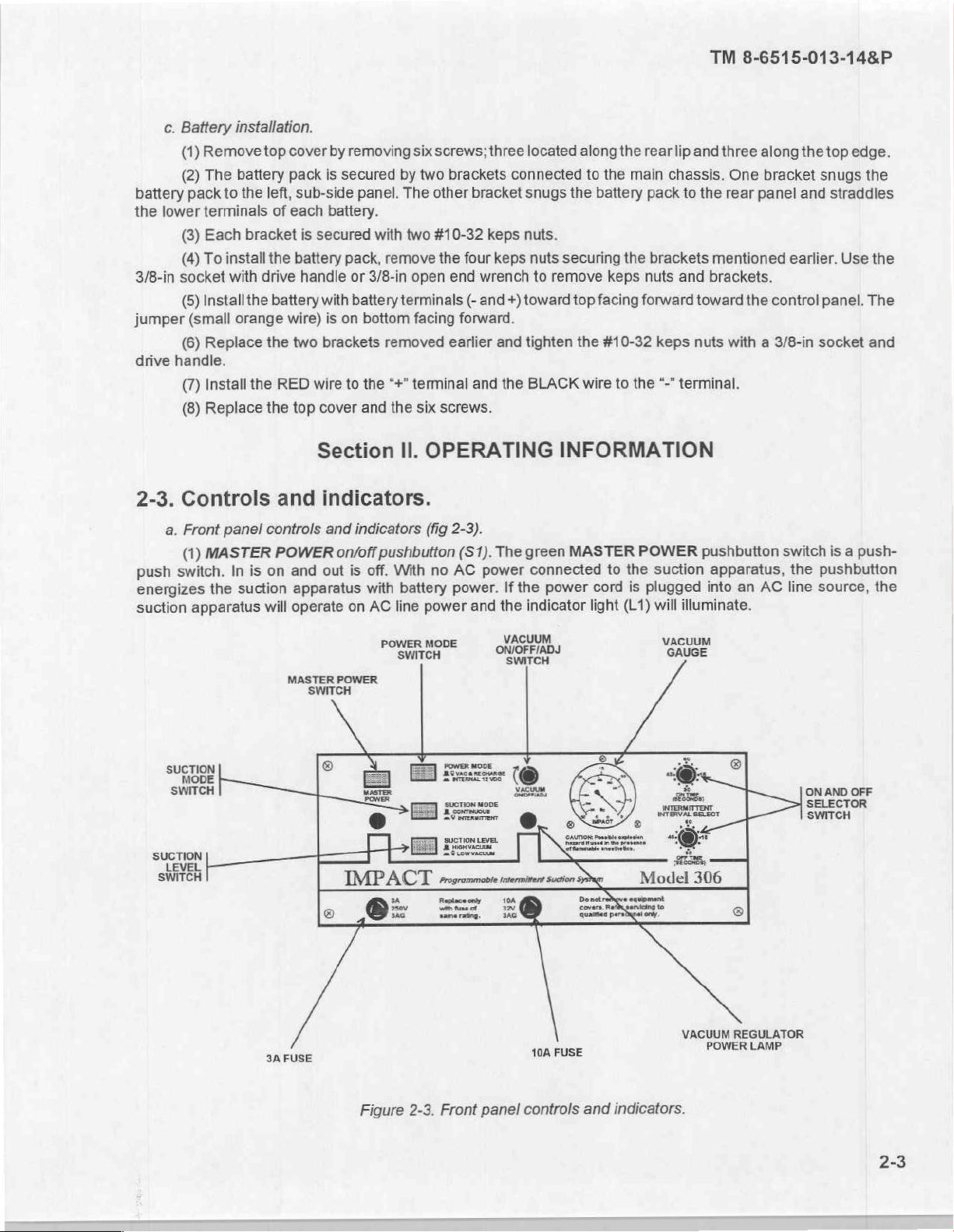
2-3.
Controls
a.
Front
(1)
push
switch.
energizes
suction
apparatus
SUCTION
MODE
SWITCH
SUCTION
LEVEL
SWITCH
panel
MASTER
In is
the
suction
LEE
Section
and
controls
POWER
on
and
apparatus
will
operate
MASTER
SWITCH
|
|
fm:
Il.
OPERATING INFORMATION
indicators.
and
indicators
on/off
out
is
on
POWER
©
IMPACT
о
ФЕ
pushbutton
off.
with
AC
的
MASTER
e
With
battery
line
POWER
SWITCH
Y
EE
æg
m
(fig
power
MODE
2-3).
(S1).
The
green
no
AC
power
connected
power.
Ss
sucTion
Er
enom
If
the
and
the
VACUUM
ONJOFF/ADJ
SWITCH
ーー
(©
а,
MODE
9
indicator
Y
oe
rrogrommoste
Fur
==
ntermirent
©
MASTER
power
à
Suction
=
to
cord
light
(L1)
POWER
the
is
plugged
о"
Model
こつ
pushbutton
suction
into
will
illuminate.
VACUUM
GAI
UGE
©+
©
gis,
ος
ss
ee
306
switch
apparatus,
an
AC
^
|
©
is a push-
the
pushbutton
line
source,
ON
AND
SELECTOR
SWITCH
the
OFF
3A
FUSE
Figure
2-3.
Front
panel
AVRETE
controls
and
indicators.
VACUUM
REGULATOR
POWER
LAMP
2-3
TM
8-6515-013-14&P
(2)
MASTER
descent
push-push
POWER
AC
line
light
less
lamp
(8)
pushbutton
line
source,
power
will
be
whether
of
designed
Master
switch
and
off
and
When
neous
is
diode
(4)
SUCTION
POWER
suction
pushbutton,
suction
off
SUCTION
conjunction
is
provided
MODE
and
operation.
and
INTERMITTENT
(5)
SUCTION
out
determines
MODE
with
by
the
CONTINUOUS
CONTINUOUS
MITTENT
center
precise
pushbutton
adjustment
suction can
suction
suction
(6)
VACUUM
of
the
control
level
of
is
set.
of
the
be
(7)
Vacuum
apparatus
made.
(8)
Vacuum
gauge
used
to
0-768
mmHg
(9)
used
during
increments
(10)
used
during
increments
(11)
used
to
(12)
used
to
and
ON
TIME
INTERMITTENT
of 5 seconds
OFF
INTERMITTENT
of 5 seconds
Fuse,
protect
Fuse,
protect
POWER
to
illuminate
POWER
with
the
indicator
in
MODE
an
the
integral
on
light
simultaneously
the
suction
power
AC
the
operating
AC
protected
MODE
pushbutton
is
CONTINUOUS
the
recharging
is a push-push
whether
CONTINUOUS
suction
LEVEL
pushbutton
the
SUCTION
suction
SUCTION
suction
operation
apparatus.
MODE
operation
will
ON/OFF/ADJ
panel.
This
suction
achieved
When
suction
the
SUCTION
between
obtained.
regulator
VACUUM
gauge.
indicate
0-30
selector
power
ON/OFF/AD4J
The
the
level
in
Hg.
switch.
each.
TIME
selector
each.
3A,
250V,
3AG
against
the
10A,
32V,
suction
excessive
3AG
level
indicator
lamp
and
verify
pushbutton
indicator
position.
recharge
apparatus
cord
against
pushbutton
When
(L2)
in
the
plugged
is
suction
of
the
potential
the
will
apparatus
batteries
(S5).
suction.
the
suction
suction
operation
pushbutton
operation
(S4).
is a push-push
MODE
pushbutton,
HIGH
of
operation
is
indicated
be
indicated
switch
switch
by
the
0-22
lamp
vacuum
of
suction
suction
switch.
suction
(F1).
current
(F2).
and
(S3).
is
used
use
of
LEVEL
in
(L3).
gauge
that
The
ON
operation.
The
OFF
operation.
Fuse
draw
Fuse
motor
(L1).
that
(S2).
lamp.
the
pushbutton
switch
battery.
operate
into
CAUTION
high
The
switch
This
apparatus
will
be
The
switch
VACUUM
when
when
The
to
this
switch
is
Hg.
When
The
switch
can
is
being
TIME
This
TIME
This
F1
is
by
F2
is
control
The
green
there
is
a
live
The
green
This
pushbutton
will
illuminate
When
the
from
the
line.
AC
an
from
an
external
is
desired,
current
green
with an
integral
pushbutton,
is in
is
indicated
indicated
when
green
with
an integral
determines
can
only
and
is
verified
the
SUCTION
the
lamp
black
VACUUM
control
set
is
will
to
HIGH,
the
SUCTION
vacuum
in
the on
easily
the
also
be
delivered
selector
switch
switch allows
selector
switch
located
the
located
on
unit
in
on
circuits
from
MASTER
power
source
master
is
in
and
the
POWER
out
the
pushbutton
internal
12
12
ensure
SUCTION
the
draw.
indicator
in
conjunction
either
when
the
the
SUCTION
indicator
whether
be
achieved
by the
MODE
is
illuminated.
ON/OFF/ADJ
level
of
vacuum
be
dependent
the
VACUUM
LEVEL
regulator
position
read
power
and
from
by the
(S6)
the
switch
allows
the
the
the
(S7)
the
front
event
front
overcurrent
POWER
will
position
suction
VDC
VDC
external
MODE
available
MODE
only
operate
apparatus
is
in
the
battery
source
12
pushbutton,
lamp
indicator
and
(L4).
with
INTERMITTENT
SUCTION
lamp
is
illuminated.
LEVEL
pushbutton,
lamp
HIGH
VACUUM
when
the
indicator
indicator
of
the
on
how
ON/OFF/ADJ
is
set
to
lamp
adjustment
several
suction
is a 1
user
feet
apparatus.
pole,
to
program
isa 1 pole,
user
to
program
panel
of
the
of
an
electrical
panel
of
the
conditions.
lamp
to
operate
pushbutton
with
the
unit
plugged
will
in
position,
power
source
and
simulta-
VDC
source
just
In
is
INTERMITTENT
the
SUCTION
or
CONTINUOUS
MODE
indicator
just
(L5).
This
or
LOW
suction
lamp
being
lamp
is
off
switch
suction
illuminates
away.
the
SUCTION
LOW,
of
suction
is
apparatus.
switch
only
It
is a mechanical
It
12
position
the
12
position
the
OFF
suction
apparatus
fault.
suction
apparatus
is
an
incan-
the
unit.
switch
the
is
MASTER
into
operate
the
indicator
regard-
below
on
AC
the
LEVEL
lamp
below
the
pushbutton,
VACUUM
apparatus
and
located
is
off.
Low
INTER-
in
the
The
LEVEL
will
allow
0-8
in
Hg
whenever
level
is
graduated
rotary
ON
TIME
rotary
TIME
the
can
switch
in
switch
in
and
and
a
an
is
in
in
of
be
in
12
12
is
is
2-4
b.
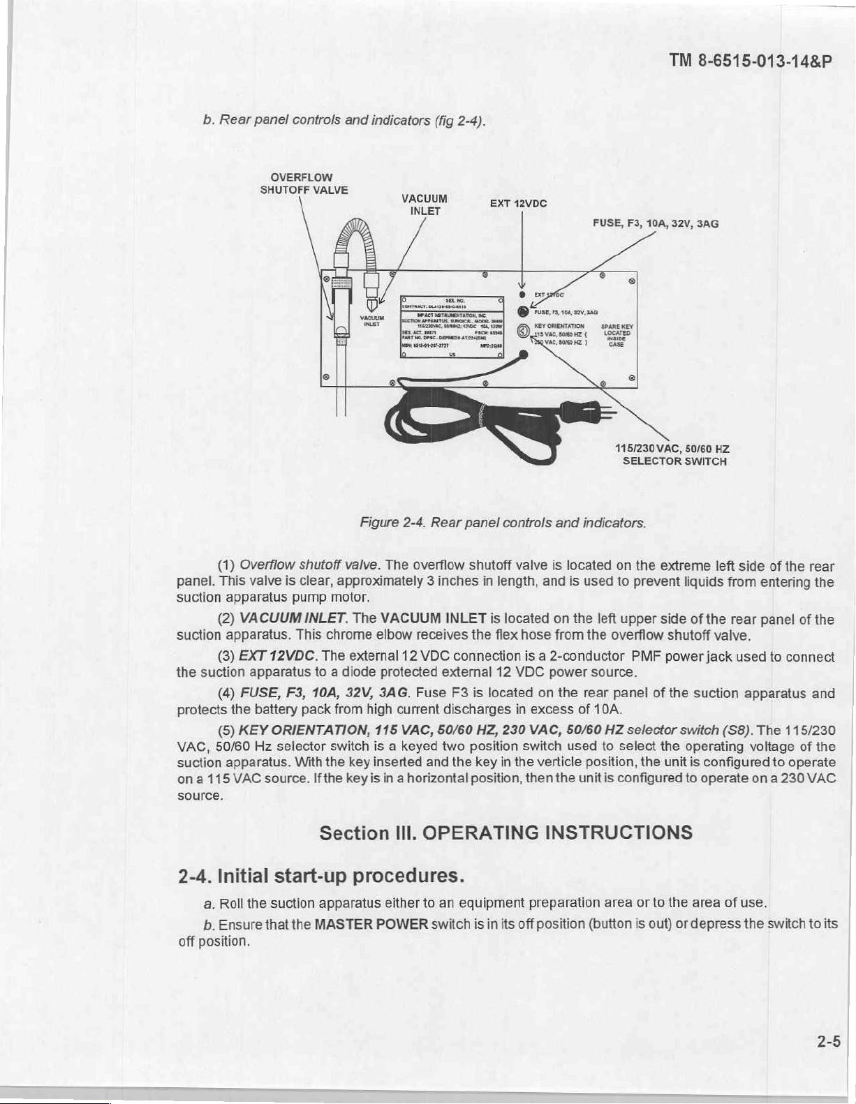
Rear
panel
OVERFLOW
SHUTOFF
controls
VALVE
and
indicators
(fig
VACUUM
INLET
2-4).
EXT
12VDC
FUSE,
F3,
10A, 32V,
TM
8-6515-013-14&P
3AG
(1)
panel.
suction
suction
the
protects
VAC,
suction
This
apparatus
(2)
apparatus.
(3)
suction
(4)
(6)
50/60
apparatus.
on a 115
source.
Overflow
valve
VACUUM
EXT
12VDC.
apparatus
FUSE,
the
battery
KEY
ORIENTATION,
Hz
VAC
source.
shutoff
is
clear,
pump
INLET.
This
chrome
The
to a diode
F3,
10A,
pack
selector
With
the
Ifthe
Figure
valve.
approximately 3 inches
motor.
The
external
32V,
from
switch
key
key
2-4.
Rear
The
overflow
VACUUM
elbow
receives
12
VDC
protected
3AG.
Fuse
high
current
115
VAC,
50/60
is a keyed
inserted and
is
in a horizontal
INLET
connection
external
F3
discharges
two
the
panel
controls
shutoff
in
length,
is
located
the
flex
12
is
located
HZ,
230
position
key
in
the
position,
and
indicators.
valve
is
located
and
is
used
on
the
left
hose
from
the
is a 2-conductor
VDC
power
source.
on
the
rear
in
excess
VAC,
switch
verticle
then
50/60
used
the
of
unit
10A.
HZ
to
position,
is
115/230
VAC,
SELECTOR
on
the
extreme
to
prevent
upper
side
overflow
panel
select
configured
shutoff
PMF
power
of
the
selector
the
the
unit
50/60
HZ
SWITCH
left
liquids
switch
operating
to
from
of
the
rear
valve.
jack
suction
(S8).
is
configured
operate
side
of
the
entering
panel
used
to
connect
apparatus
The
115/230
voltage
to
on a 230
rear
the
of
the
and
of
the
operate
VAC
2-4.
a.
b.
off
position.
Initial
Roll
Ensure
start-up
the
suction
that the
Section
procedures.
apparatus
MASTER
POWER
III.
OPERATING
either
to
switch
an
equipment
is
in
INSTRUCTIONS
preparation
its
off
position
area
or
(button
to
is
the
out)
area
or
depress
of
use.
the
switch
to
2-5
its
TM
8-6515-013-14&P
Verify
jes
c.
Remove
also be
dures
power
indicator
modes.
the
patient
powered
d.
Ensure
contained
e.
Depress
source.
f.
Verify
continuous
lamp
g.
Verify
that
The
SUCTION
h.
Test
the
i.
Submerge
aspiration
j.
Remove
use
of
by
that
for
EVR
the
qualified
operating
and
external
the
coiled
by
the
the
in
paragraph
the
MASTER
power
12
electrical
internal
collection
2-2b.
POWER
operation
continuous
intermittent suction
by
adjusting
the
end
the
water
PVC
patient
MODE
of
the
into
operation
indicator
polyvinyl
the
tubing
medical
selections
VDC,
at
the
power
cable
12
VDC
batteries
bottle
assembly
switch
at
both
high
will
operates
lamp
vacuum
in
the
chloride
collection
from
the
personnel.
NOTE
at
115
back
of
assembly
or
is
to
the
on
and
low
not
illuminate
only
in
will
illuminate
high
and
(PVC)
bottle.
container
or
230
VAC,
the
unit,
and
external
in
place
position.
ranges
in
the low
in
low
ranges
patient
of
water.
connect
12
VDC.
and
assembled
The
in
each
this
mode.
vacuum
this
tubing
The
internal
rechargeable
it
to
the
in
indicator
of
the
range
lamp
in
proper
operating
mode.
in
each
ofthe
into a container
suction
apparatus
voltage.
accordance
illuminates
power
each
of
the
operating
of
is
batter-
The
with
to
operating
power
water
now
ready
unit
may
the
proce-
verify a live
modes.
and
The
power
modes.
observe
for
2-5.
Routine
Routine
start-up
assembly
2-6.
Operating
Observe
a.
unit's
standard
Observe
b.
only
bottle
Always
c.
overflows
stick.
disposable
A
д.
overflow
occurs,
brane
designed
filter.
this
start-up
procedures
and
interconnections
periodically
operating
patient.
the
would
the
the
the
use
may
valve
membrane
the
bacteria
to
patient
flow
vacuum
filter
Failure
graduation
to
ter
sultant
when
which
shutoff
retain
to
procedures.
will
follow
in
accordance
procedures.
level
the
procedures.
collection
will
In
fail
patient
of
which
final
result
risk.
which
the
shutoff
in
addition,
liquid
from
fluids
is
pump
shutoff
damage
both
is
collection
contacts
would
empty
also
overflow
permanently
and
the
initial
with
in
liquid
of
bottle
the
of
overflow
the
if
contamination
the
within
running.
provided
valve
the
hydrophobic
bottle.
aspirate,
otherwise
start-up
your
collection
the
CAUTION
prior
vacuum
protection
clear
vacuum
and
filter
This
following
or
be
procedures
units
standard
bottles
liquid
a
to
the
to
device
shut
and
tubing.
PVC
this
with
pump.
Ensure
bacterial
should
150
exhausted
and
level
patient
would
the
off
Fluids
to
unit
that
provided.
is
replaced
be
cumulative
the
into
except
operating
empty
reaching
a
pose
and
fail,
should
the
overflow
the
with
suction
protect
This
when
hours
immediate
for
differences
procedures.
accordance
in
it
1500
its
potential
bacteria
the
higher
a
drawn
be
suction
shutoff
connects
filter
discoloration
use.
of
vicinity.
involving
with
mL
risk
fil-
re-
collection
the
into
mechanism
valves
between
its
of
filter
This
NOT
DO
your
from
not
do
the
mem-
is
bypass
2-6
2-7.
Shut-down
procedures.
TM
8-6515-013-14&P
Shut-down
a,
Depress
b.
Disconnect
ο.
Dispose
procedures.
2-8.
Associated
The
suction
battery
or
erator
2-9.
Associated
Associated
Section
2-10.
fecting,
designed
General.
a.
The
and/or
b.
Accessories
and
c.
The
procedures
the
MASTER
the
of
the
Section
apparatus
operation.
material
suction
collection
is
apparatus
sterilizing
identified
manufactured
are
as
follows:
POWER
tubing
tubing
from
and
IV.
OPERATION
support
requires
no
material.
identified
V.
CLEANING,
and
procedures
as
for a one
bottle
assembly
switch
the
patient
collected
patient
items
associated
in
appendix D and
DISINFECTING,
PROCEDURES
operating
disposable
are
provided
time
should
accessories
should
use
so
the
power
to
the
collection
fluids
OF
of
equipment.
support
be
items
appendix
in
subsequent
not
only.
removed
light
is
not
bottle.
in
accordance
AUXILIARY
of
equipment
E.
AND
should
be
be
cleaned
from
the
clean
paragraphs.
or
base
lit.
with
your
EQUIPMENT
otherthan
STERILIZING
at
all
times.
reused.
These
assembly
unit's
standard
an
electrical
Specific
accessories
to
facilitate
operating
power
gen-
cleaning,
cleaning.
disin-
were
2-11.
a.
Cleaning.
(1)
(2)
(3)
(4)
(5)
b.
Disinfecting.
with
disinfectant
c.
Sterilizing.
Suction
Turn
off
the
Disconnect
Remove
Wipe
Dry
the
the
in
the
suction
The
apparatus.
suction
the
collection
suction
Disinfect
accordance
suction
apparatus
electrical
bottle
Do
not
apparatus
apparatus
the
suction
with
apparatus
by
depressing
power
cable
assembly.
allow
liquids
using a mild
with a soft
apparatus
your
unit's
cannot
the
MASTER
assembly
from
the
CAUTION
to
enter
the
control
detergent
cloth.
by
wiping
standard
be
sterilized.
with a soft
it
with a liquid
operating
POWER
electrical
system.
procedures.
switch
receptacle.
cloth.
disinfectant
to
the
or
off
position.
lightly
spraying
it
TM
8-6515-013-14&P
2-12.
Collection
a.
Cleaning.
(1)
(2)
use:
each
(3)
been
in
contact
(4)
(5)
accordance
(6)
dures.
Then
(7)
(8)
b.
Sterilizing.
the
steam
Turn
off
the
In
general,
(a)
Patient
(b)
1/4-in
The
(a)
1/4-in
(b)
3/8-in
Remove
Immerse
with
Discard
based
cracking
Dispose
the
hose
id
following
with
patient
id
id
by
the
the
your
overflow
detergents
of
of
any
immerse
Scrub
the
cap
Rinse
all
assemblies
Steam
sterilizer's
manufacturer
bottle
suction
by
by
caps
unit's
the
apparatus
following
12-in
items
can
fluids:
18-in
10-in
Lg
from
caps
and
standard
valve
the
rubber.
patient
collection
assemblies
sterilize the
assembly.
hoses
jumper
Lg
on
thoroughly
hose
be
reused
hose
between
hose
between
the
collection
those
hoses
operating
if
it
has
rubber
drainage
bottles
lightly
reusable
instructions
by
depressing
are
not
reusable
between
after
cleaning,
bottle
top
of
bottles.
not
procedures.
CAUTION
been
in
products,
fluids
in
in
the
with a nylon
in
warm
caps
and your
the
and
bottles
provided
#2
and
disposable
specified
contact
as
it
with
will
accordance
detergent
brush
water
and
and
collection
unit's
MASTER
should
be
it
bottom
filter
and
in
a(2)
above
patient
potentially
fluids.
with
solution.
in
warm
allow
them
bottles
standard
POWER
switch.
disconnected
can
be
established
of
disposable
bottom
of
in a warm
Never
lead
to
dry
your
unit's
detergent
to
dry.
for
15
operating
and
filter
overflow
detergent
use
alcohol
rotting
standard
solution.
minutes
in
procedures.
disposed
that
they
shutoff
solution
and
operating
accordance
of
after
have
valve
proce-
with
not
in
2-13.
The
mobile
Section
Unusual
suction
VI.
OPERATION UNDER
conditions.
apparatus
is
designed
to
operate
UNUSUAL
only
within a medical
CONDITIONS
treatment
facility
environment.
TM
8-6515-013-14&P
3-1.
Overview.
a.
Unit
level
maintenance.
on
its
assigned
(1)
personnel
checking
accessories,
sembly
or
(2)
Medical
Equipment
cation/certification
modules,
class
repair
tion,
and
services
in
equipment,
b.
Maintenance
scope
personnel
the
of
vacuum
equipment.
Operator
and
forfrayed
reassembly
Specialist
maintenance.
consists
cables,
and
replacing
of
maintenance.
Repairers.
(a)
Scheduling
(CVC)
(b)
Performing
or
PCBs,
(c)
parts
(d)
related
(e)
(f)
when
Operating a repair
used
Maintaining a library
materials.
Conducting
Establishing
accordance
(g)
Notifying
assemblies,
functions.
the
operator/user
will
perform
pump, PCBs,
UNIT
Section
This
level
Responsibilities
This
of
equipment
and
stowing
operator
the
end
item,
This
The
functions
and
performing
services.
unscheduled
available.
parts
on
medical
inspections
administrative
with
support
or
modules.
are
the
majority
or
equipment.
of
technical
TB
38-750-2.
maintenance
Maintenance
assigned
of
stand.
CHAPTER
LEVEL
I.
GENERAL
of
maintenance
are
segment
operational
items
not
repair
parts.
critical
adjustments
segment
and
PMCS,
maintenance
program
on
new
maintenance
electrical
to
manuals
or
transferred
procedures
battalions
functions,
to
unit
3
MAINTENANCE
INFORMATION
is
the
responsibility
stratified
of
functions;
in
Replacing
of
services
include
level
as
unit
level
use;
and
after
unit
safety
functions
Class
(TMs),
for
of
both
Maintenance
required
follows:
maintenance
routine
checking
services
operator
replacement,
level
maintenance
include—
inspections
with
VIII
repair
manufacturers’
equipment.
the
control
requirements
preventive
for
the
equipment
of
is
like
forloose
parts
will
orthe
and
emphasis
parts
and
administration
and/or
and
corrective,
Equipment
and
performed
performed
cleaning,
hardware,
not
require
extensive
is
performed
tests,
and
on
replacing
as
well
as
literature,
repair
evacuating
which
Repairer
except
some
by
a
using
unit
by
operator/user
dusting,
replacing
extensive
calibration/verifi-
use
only
washing,
operator
disas-
oftools.
by
trained
assemblies,
other
commodity
parts
informa-
of
maintenance
unserviceable
are
beyond
personnel.
tasks involving
the
These
3-2.
Tools
Common
B,
tools
section
authorized
3-3.
Components
Components
3-4.
Expendable
Expendable
appendix
D,
and
and
III
of
this
items.
of
end
and
section
test
test
equipment
manual.
item
durable
II
of
equipment.
required
Refer
to
your
of
end
item
and
basic
issue items
supplies.
supplies
this
and
manual.
for
unit
units
and
are
materials
level
maintenance
modified
basic
listed
reguired
table
of
issue
in
appendix
for
maintenance
of
the
equipment
organization
items.
C,
sections
of
the
are
and
equipment
II
and
eguipment
listed
III
of
this
are
in
appendix
(MTOE)
manual.
listed
for
in
TM
8-6515-013-14&P
3-5.
Repair
parts.
Repair
3-6.
Special
Special
manual.
3-7.
Unpacking
a.
Open
b.
Remove
©.
Open
d.
Remove
e.
Lift
f.
Open
g.
Verify
(1)
(2)
(3)
(4)
(5)
(6)
(7)
(8)
(9)
(10)
(11)
(12)
(13)
(14)
(15)
(16)
(17)
parts
required
for
tools.
tools
required
for
Section
the top
the
and
the
receipt
Suction
Assembly,
Hose, corrugated,
3/8-in
1/4-in
1/4-in
Maintenance
Operation
Spare
Spare
Filter,
Reusable
Holder,
Wall
Screws,
Cart
Battery
flaps
the
two
top
of
the
the
foam
roll
the
suction
small
box
of
the
apparatus.
overflow
id
by 10
id
by 1 1/2
id
by 5 ft
manuals
fuse,
type
fuse,
disposable,
collection
collection
mounting
self-tapping
for
suction
pack.
unit
level
maintenance
unit
level
maintenance
II.
SERVICE
the
suction
of
the
shipping
boxes
from
inside
large
box.
blocks
ft
and
type
from
the
apparatus
with
accessories
following:
shutoff
8-in
long.
length
of
ft
length
length
of
service
(2).
3AG,
10A,
3AG,
hydrophobic/bacterial.
canister
canister
bracket
(for
apparatus.
out
valve.
tubing,
of
tubing,
tubing,
manuals
32V
3A,
250V.
system
(2).
(for
collection
wall
are
listed
of
the
equipment
UPON
RECEIPT
apparatus.
container.
the
shipping
box and
of
the
and
remove
clear.
clear.
clear.
(2).
(2).
mounting
container.
set
them
box.
(2
bottles
canisters).
brackets)
in
aside.
the
contents.
with
appendix
are
OF
caps).
(4).
E,
section
listed
in
appendix
EQUIPMENT
Set
the
box
II
of
this
aside.
manual.
E,
section
III
of
this
3-8.
General.
No
lubrication
3-2
of
Section
the
suction
Ill.
apparatus
LUBRICATION
is
required.
INSTRUCTIONS
TM
8-6515-013-14&P
Section
3-9.
General.
a.
The
operation
damage
b.
Table
table
is
also
not
limited
should
operational
PMCS
c.
Table
d.
Some
do
table
IV.
suction
at
all
times.
or
failure.
3-1
referred
to
performing
any
time
indicators,
3-2
is
also
items
provide a quality
procedures
e.
each
equipment
During
with
daily
to
be
The
following
column:
(1)
Item
number.
area
(2)
Interval.
Operation, A -
use
of
on
the
PREVENTIVE
apparatus
Inspection
contains a list
to
as “-10
they
and
contains a list
referred
to
be
control
accomplished
is a list
the
This
After
equipment.
must
will
of
PMCS"
the
checks
need
to
maintaining
of
to
as
inspected
check
on
by
of
both
This
column
Equipment
column
shows
Operation, © -
MAINTENANCE
be
inspected
allow
defects
items
to
requirements.
and
services
be
done,
the
items
to
“-20
PMCS"
will
be
listed
multiple
unit
level
PMCS
table
shows
Inspection
when
Quarterly,
and
serviced
to
be
discovered
be
performed
Preventive
in
table
such
as
checking
proper
be
quantities
performed
requirements.
in
both
table
operator/user
Medical
column
the
sequence
and
each
Equipment
headings
Maintenance
PMCS
and S -
CHECKS
systematically
and
by
unit
level
maintenance
3-1.
There
general
of
accessories.
by
unit
level
3-1
and
personnel,
Repairers.
with a description
in
which
to
do
Worksheet,
item
is
to
Semiannually.
to
corrected
operator/user
are
cleanliness,
Medical
table
and
the
be
serviced: B -
before
by
things
Equipment
3-2
to
to
identify
PMCS,
DA
B,
D,
AND
operator/user
ensure
they
personnel.
SERVICES
that
result
operator/user
observing
Repairers.
stress
their
more
comprehensive
of
the
information
and
is
used
Form
2404.
Before
and A should
it
is
ready
for
in
serious
This
PMCS
personnel
is
personnel
for
improper
This
importance,
to
identify
found
the
to
in
Operation, D -
be
performed
(3)
checked
(4)
able
or
When
ice
only
checks
Item
to
or
serviced.
Equipment
unusable.
the
suction
those
and
services
be
Inspected
is
not
apparatus
items
when
and
must
that
will
the
Procedure.
Ready/Available
NOTE
be
kept
not
disrupt
equipment
This
column
If:.
This
column
in
continuous
operation.
can
be
shut
identifies
lists
operation,
Perform
down.
the
general
conditions
that
the
check
complete
area
make
the
and
serv-
daily
or
specific
equipment
part
to
unavail-
be
3-3
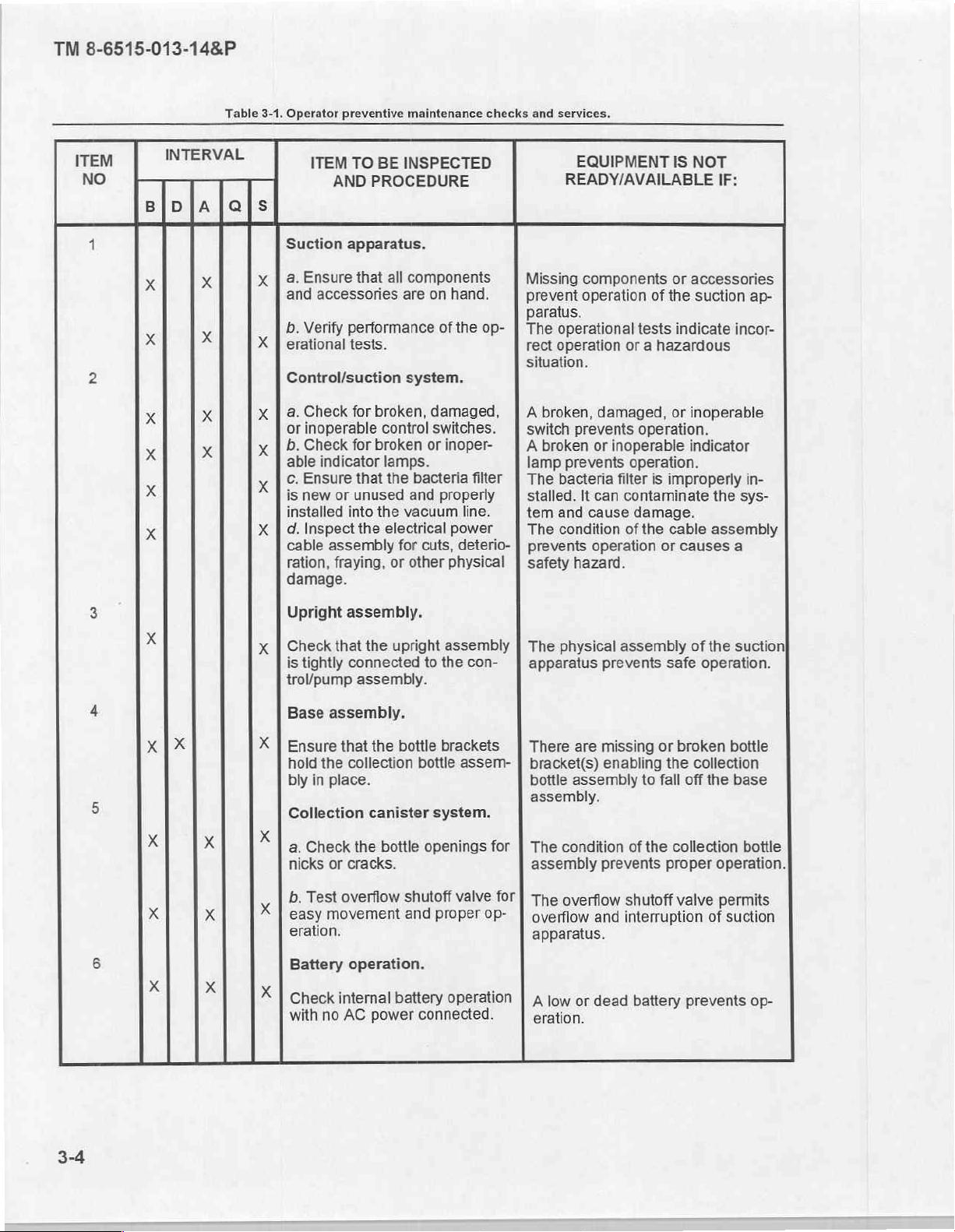
TM
8-6515-013-14&P
Table
3-1.
Operator
preventive
maintenance
checks
and
services.
ITEM
INTERVAL
DIA
Q
ITEM
TO
BE
AND
PROCEDURE
Suction
a.
and
b.
erational
Control/suction
a.
or
b.
able
c.
is
installed
d.
cable
ration,
damage.
apparatus.
Ensure
Verify
Check
inoperable
Check
Ensure
new
Inspect
that
accessories
performance
tests.
for
for
indicator
that the
or
unused
into
the
assembly
fraying,
all
broken,
control
broken
lamps.
the
electrical
or
INSPECTED
components
are
on
hand.
of
the op-
system.
damaged,
switches.
or
inoper-
bacteria
and
properly
vacuum
power
for
cuts,
other
physical
filter
line.
deterio-
EQUIPMENT
READY/AVAILABLE
Missing
prevent
paratus.
The
rect
situation.
A
switch
A
lamp
The
stalled.
tem
The
prevents
safety
components
operation
operational
operation
broken,
broken
damaged,
prevents
or
prevents
bacteria
It
can
and
cause
condition
operation
hazard.
IS
NOT
or
accessories
of
the
tests
indicate
or a hazardous
or
inoperable
operation.
inoperable
operation.
filter
contaminate
damage.
of
the
indicator
is
improperly
cable
or
causes
IF:
suction
incor-
the
sys-
assembly
a
ap-
in-
Upright
Check
is
trol/pump
Base
Ensure
hold
bly
Collection
a.
nicks
b.
easy
eration.
Battery
Check
with
assembly.
that
tightly
connected
assembly.
that the
the
collection
in
place.
Check
or
cracks.
Test
overflow
movement
operation.
internal
no
AC
assembly.
the
the
upright
bottle
bottle
canister
bottle
shutoff
and
battery
power
connected.
assembly
to
the
con-
brackets
assem-
system.
openings
valve
proper
operation
The
for
for
op-
physical
apparatus
There
are
bracket(s)
bottle
assembly
assembly.
The
condition
assembly
The
overflow
overflow
apparatus.
A
low
eration.
prevents
missing
enabling
prevents
and
or
dead
assembly
safe
or
broken
the
to
fall
of
the
collection
proper
shutoff
interruption
valve
battery
of
the
suction
operation.
bottle
collection
off
the
base
bottle
operation.
permits
of
suction
prevents
op-
3-4
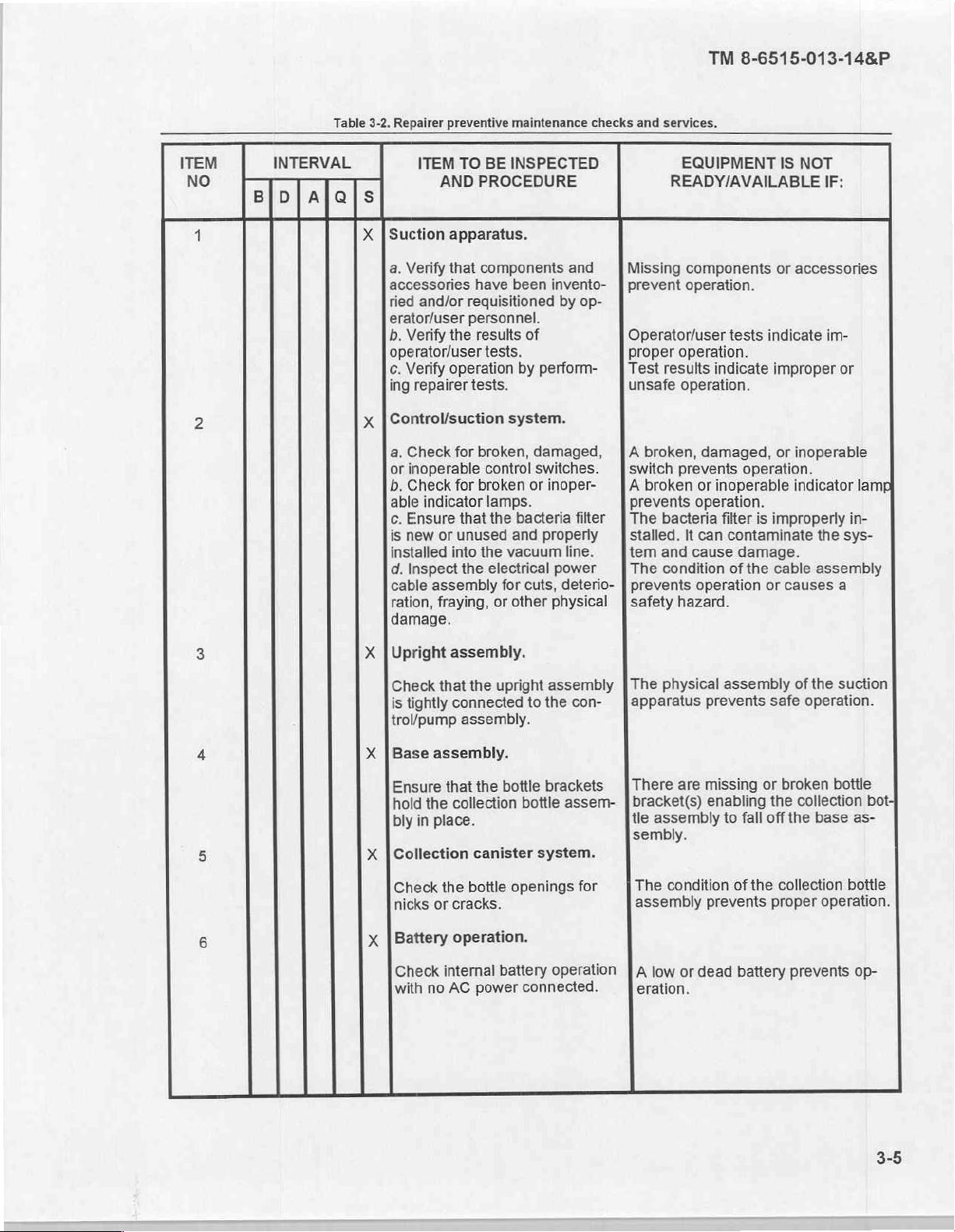
ITEM
NO
BID
INTERVAL
A
Table
3-2.
ais
X | Suction
x
Repairer
a.
accessories
tied
erator/user
b.
operator/user
c.
ing
|Control/suction
a.
or
b.
able
c.
is
installed
d.
cable
ration,
damage.
preventive
ITEM
TO
AND
PROCEDURE
apparatus.
Verify
that
components
have
and/or
Verify
Verify
repairer
Check
inoperable
Check
Ensure
new
Inspect
requisitioned
personnel.
the
results
tests.
operation
tests.
for
broken,
for
broken
indicator
that
or
unused
into
the
the
assembly
fraying,
maintenance
BE
INSPECTED
been
of
by
system.
damaged,
control
lamps.
switches.
or
the
bacteria
and
vacuum
electrical
for
cuts,
or
other
checks
and
invento-
by op-
perform-
inoper-
filter
properly
line.
power
deterio-
physical
TM
and
services.
EQUIPMENT
READY/AVAILABLE
Missing
prevent
Operator/user
proper
Test
unsafe
A
switch
A
prevents
The
stalled.
tem
The
prevents
safety
components
operation.
operation.
results
operation.
broken,
prevents
broken
bacteria
It
and
condition
hazard.
indicate
damaged,
or
inoperable
operation.
filter
can
cause
operation
8-6515-013-14&P
IS
NOT
IF:
or
accessories
tests
indicate
improper
or
operation.
is
improperly
contaminate
damage.
of
the
cable
or
im-
inoperable
indicator
the
assembly
causes
or
sys-
a
lamp
in-
Х | Upright
Check
is
trol/pump
X | Base
Ensure
hold
bly
X
x
assembly.
that
the
tightly
connected
assembly.
assembly.
that
the
the
collection
in
place.
[Collection
Check
nicks
[Battery
Check
with
canister
the
boitle
or
cracks.
operation.
internal
no
AC
power
upright
to
the
bottle
brackets
bottle
system.
openings
battery
connected.
assembly
con-
assem-
for
operation
The
physical
apparatus
There
bracket(s)
tle
assembly
sembly.
The
condition
assembly
A
low
eration.
are
or
dead
assembly
prevents
missing
enabling
to
fall
of
the
prevents
battery
of
the
safe
operation.
or
broken
the
collection
off
the
base
collection
proper
prevents
suction
bottle
bottle
operation.
bot;
as-
op-
TM
8-6515-013-14&P
3-10.
Operator/user
that
with
Reporting
unable
are
they
your
unit's
personnel
to
Medical
assistance.
3-11.
This
sonnel
should
3-12.
VDC,
nected
will
VACUUM
level.
General.
section
contains
and
be
reported
Medical
Operator/user
Notify
a,
CONTINUOUS
(1)
Verify
operating
and
size
of
unit
(2)
Verify
that
in
accordance
(3)
Depress
(4)
Select
CONTINUOUS
not
illuminate
(5)
Select
LOW
is
selected.
(6)
Turn
the
The
EVR
indicator
to
your
the
the
in
this
VACUUM
counterclockwise.
(7)
Using
your
selected
the
aspiration
INTERMITTENT
level.
VACUUM
(8)
Allow
(9)
Open
of
water
(10)
Vacuum
(11)
Verify
(12)
Remove
b.
INTERMITTENT
(1)
Perform
(2)
The
Remember
switch.
air
to
the
end
into
readings
CONTINUOUS
the
the
SUCTION
operation.
deficiencies.
will
report
problems
correct.
Referto
Equipment
Section
procedures
Equipment
Medical
tests.
unit's
Medical
suction
for
with
MASTER
VACUUM
thumb,
evacuate
of
the
first
operation.
power
voltage
components
the
mode.
switch
lamp
close
that
the
PVC
collection
may
PVC
patient
suction
three
MODE
Equipment
procedures
will
the
TB
Repairer
V.
for
operational
Repairer
Equipment
selections
selections.
and
POWER
suction
with
the
clockwise
remain
the
open
maximum
from any
patient
bottles.
be
read
operation
tubing
operation.
steps
from
and
SUCTION
with
the
suction
38-750-2
or
and
request
help
OPERATIONAL
testing
personnel.
Repairer
at
accessories
contained
switch
from
SUCTION
on
end
collection
tubing
directly
at
from
CONTINUOUS
NOTE
Repairer
115
or
to
the
SUCTION
to
its
on
until
the
of
vacuum
and
from
both
the
LEVEL
personnel.
230
of
in
the
LEVEL
position
VACUUM
the
limit
bottle
submerge
high
container
apparatus
deficiency
the
report
through
the
TESTING
of
the
suction
Deficiencies
if
any
operator/user
VAC,
internal
the
suction
paragraph
on
position.
MODE
switch.
PVC
patient
is
regulated
system
the
front
and
operation.
switches
apparatus
2-2.
switch.
An
and
continue
switch
tubing
when
it
into a container
panel
low
ranges
of
water
must
discovered
using
telemaintenance
apparatus
identified
by
by
tests
rechargeable
are
The
indicator
indicator
(EVR)
by
rotating
to
allow
the
SUCTION
lamp
is
preselecting
vacuum
of
and
the
SUCTION
perform
be
depressed
gauge.
during
their
forms.
proper
the
system
both
operator/user
operator/user
fail.
batteries,
assembled
lamp
for
and
illuminates
itto
the
desired
clicked
the
off
by
vacuum
LEVEL
the
vacuum
of
water
and
LEVEL
the
next
test.
and
illuminated
‘-10
PMCS"
Consult
if
you
need
personnel
external
intercon-
this
switch
when
LOW
vacuum
turning
to
reach
switch
limit.
observe
switch.
per-
12
fully
its
and
the
for
3-6
(3)
Preselect
(4)
Adjust
range.
Each
(5)
(6)
Close
Open
aspiration
(7)
Vacuum
(8)
Remove
with
your
unit's
To
during
the
circuit
of
water
prevent
dangerous
INTERMITTENT
LOW
VACUUM
the
desired
the
ON
and
is
programmable
the
open
the
end
of
into
the
readings
the
PVC
standard
level
vacuum
OFF
TIME
end
of
the
the
PVC
patient
collection
may
be
patient
operating
HIGH
VACUUM
suctioning,
range
only.
level
as
at
the
INTERMITTENT
in
12
increments
PVC
patient
tubing
bottles.
read
directly
tubing
from
procedures.
NOTE
levels
a
safety
described
of
tubing
and
submerge
from
the
the
container
from
lockout
in
the
5
seconds
to
allow
front
of
appearing
allows
previous
INTERVAL
each
the
it
into a container
panel
water
this
for
vacuum
vacuum
and
dispose
at
mode
section.
SELECT
TM
the
a
total
to
reach
gauge.
8-6515-013-14&P
pump
output
to
operate
section
of
its
of
water
the
in
to
the
144
combinations.
selected
and
observe
water
in
accordance
desired
level.
the
3-13.
a.
VDC.
Select
fully
charged
nected
open
end
that
the
50
mmHg.
either
the
PVC
b.
VDC.
Select
fully
charged
nected
Medical
Vacuum
(1)
Verify
and
to
(2)
Verify
in
accordance
(3)
Connect a mercury
of
the
(4)
Depress
(5)
Select
(6)
Turn
(7)
Observe
vacuum
(8)
Select
(9)
Perform
vacuum
(10)
Depress
(11)
Remove
Equipment
levels.
operating
apply
check
that the
PVC
the
CONTINUOUS
vacuum
the
level
HIGH
the
level
is
the
the
patient tubing.
(12)
Shut
down
Intermittent
(1)
Verify
(2)
Verify
in
accordance
(3)
Depress
(4)
Select
on/off
operating
and
apply
to
check
that the
the
INTERMITTENT
power
selections
the
power
that
calibration.
components
with the
procedures
manometer, a calibrated
patient tubing.
MASTER
POWER
and
regulator
mercury
is
at
VACUUM
applicable
less
MASTER
mercury
the
timing
power
the
on
manometer,
200
mmHg
and
troubleshooting
than
or
more
POWER
manometer,
suction
apparatus
cycles.
selections
power
that
calibration.
components
with
the
procedures
MASTER
POWER
and
Repairer
at
115
is
going
to
and
accessories
contained
switch
LOW
VACUUM
and
fully
clockwise.
the
+/-
25
mmHg.
CONTINUOUS
than
the
switch
the
by
at
115
is
going
and
accessories
contained
switch
LOW
VACUUM
tests.
0r230
VAC,
be
used.
of
the
in
paragraph
vacuum
to
the on
operation.
calibrated
Adjust
operation.
procedures
specified
to
the
calibrated
following
or
230
to
be
used.
of
in
paragraph
to
the
on
operation.
internal
If
battery
suction
position.
vacuum
R2
in
levels.
off
position.
vacuum
the
procedures
VAC,
internal
If
battery
the
suction
position.
rechargeable
power
apparatus
2-2.
gauge,
if
necessary.
Maximum
or
gauge,
or
vacuum
accordance
gauge,
in
rechargeable
power
apparatus
2-2.
batteries,
is
used,
make
sure
are
assembled
the
calibrator-analyzer
the
calibrator-analyzer.
should
with
this
or
the
paragraph
be
chapter,
calibrator-analyzer
2-7.
batteries,
is
used,
make
sure
are
assembled
or
extemal
batteries
and
intercon-
into
550
mmHg
section
or
external
batteries
and
intercon-
12
are
the
Verify
+/-
VI,
if
from
12
are
3-7
TM
8-6515-013-14&P
(5)
Set
on/off
An
this
ratus
on
(6)
Adjust
(7)
Adjust
(8)
Record
(9)
Perform
cannot
unit
the
(10)
Depress
(11)
Shut
times
for 5 seconds
oscilloscope
section.
may
However,
using a stopwatch.
and
off
R36
to
R35
to
the
vacuum
the
applicable
calibrated
be
the
down
the
as the
set the
set
the
to
MASTER
suction
reference
ON
OFF
pump
on
and 5 seconds
be
used
to
calibrate
the
technician
In
such
cases,
for
keying
TIME
circuits
TIME
circuits
cycle
on/off
troubleshooting
specification.
POWER
apparatus
switch
by
NOTE
the
may
find
the
technician
the
stopwatch.
for
5
seconds.
for
5
seconds.
periods
procedures
following
to
the
if
off
the
off.
on/off
timing
it
easier
to
Adjustment
Adjustment
less
than
in
accordance
position.
procedures
circuits
calibrate
can
utilize
should
should
or
more
contained
as
the
the
than
with
described
suction
pump
be
be
this
within
within
the
specified
chapter,
in
paragraph
appa-
turning
in
+/-0.5
+/-0.5
seconds.
period.
section
seconds.
VI,
2-7.
if
3-14.
Repairer
General.
a.
Troubleshooting
personnel
operator/user
b.
This
manual
by
routine
3-15.
Operator/user
causes
SYMPTOM
diagnostic
Operator/user
and
corrective
POSSIBLE
4.
POWER
INDICATOR
MASTER
information
is
provided
personnel
will
cannotlist
procedures,
troubleshooting
maintenance.
CAUSE
CORRECTIVE
LAMP
POWER
switch
Section
in
be
indicated
all
possible
notify
VI.
for
suction
this
section.
by
malfunctions.
your
TROUBLESHOOTING
apparatus
Corrective
the
phrase
appropriate
troubleshooting.
procedures
Table
MAINTENANCE
DOES
not
are
provided
3-3.
Operator/user
NOT
ILLUMINATE.
depressed
to
operator/user
actions
“Notify
Ifa
malfunction
maintenance
in
table
troubleshooting.
on
position.
your
3-3.
personnel
beyond
unit's
Medical
is
either
support
Each
symptom
and
the
capability
Equipment
not
listed
unit.
for
Medical
oris
is
followed
Equipment
or
authority
Repairer.”
not
determined
by
possible
of
3-8
Depress
Electrical
Connect
When
operating
Recharge
Fuse
(F1)
Check
MASTER
power
cable
the
off
battery;
3A
250 V blown.
fuse;
POWER
assembly
electrical
an
internal
if
problem
if
blown,
notify
switch.
not
connected
power
cable
battery,
persists,
unit's
to
the
battery
Medical
to
an
AC
source
correct
may
notify unit's
electrical
be
discharged.
Medical
Equipment
of
electrical
receptacle.
Equipment
Repairer.
power.
Repairer.
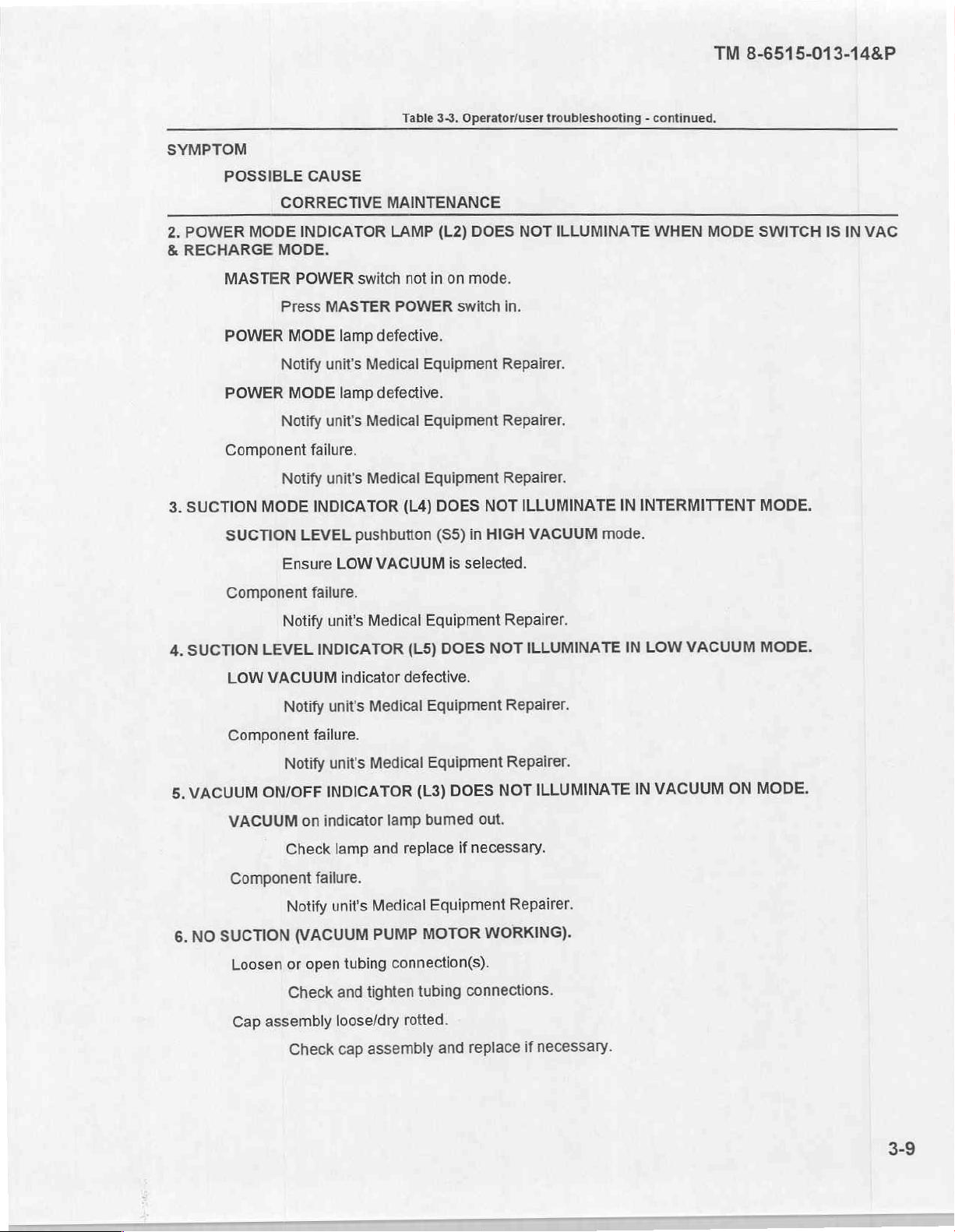
SYMPTOM
2.
POWER
&
RECHARGE
POSSIBLE
CORRECTIVE
MODE
MODE.
CAUSE
INDICATOR
Table
3-3.
Operator/user
MAINTENANCE
LAMP
(L2)
DOES
troubleshooting - continued.
NOT
ILLUMINATE
WHEN
TM
8-6515-013-14&P
MODE
SWITCH
IS IN
VAC
3.
SUCTION
SUCTION
4.
MASTER
Press
POWER
MODE
Notify
POWER
MODE
Notify
Component
Notify
MODE
SUCTION
Ensure
Component
Notify
LEVEL
LOW
VACUUM
Notify
POWER
MASTER
lamp
unit's
lamp
unit's
failure.
unit's
INDICATOR
LEVEL
LOW
failure.
unit's
INDICATOR
indicator
unit's
switch
not
POWER
defective.
Medical
defective.
Medical
Medical
(L4)
pushbutton
VACUUM
Medical
(L5)
defective.
Medical
in
on
mode.
switch
Equipment
Equipment
Equipment
DOES
(S5)
NOT
in
HIGH
is
selected.
Equipment
DOES
Equipment
in.
Repairer.
Repairer.
Repairer.
ILLUMINATE
VACUUM
Repairer.
ILLUMINATE
NOT
Repairer.
IN
INTERMITTENT
mode.
LOW
IN
VACUUM
MODE.
MODE.
VACUUM
5.
NO
6.
Component
ON/OFF
VACUUM
Component
SUCTION
Loosen
Cap
assembly
failure.
Notify
INDICATOR
on
indicator
Check
failure.
Notify
(VACUUM
or
open
Check
Check
unit's
Medical
lamp
and
unit's
Medical
PUMP
tubing
and
tighten
loose/dry
assembly
cap
Equipment
DOES
(L3)
lamp
bumed
replace
out.
if
necessary.
Equipment
MOTOR
WORKING).
connection(s).
tubing
connections.
rotted.
replace
and
Repairer.
ILLUMINATE
NOT
Repairer.
necessary.
if
IN
VACUUM
ON
MODE.
 Loading...