

Page 1
R8VTPS 8 MP IP Varifocal 150 ft IR
Turret Camera Quick Installation Guide
This 8.0 MP IP turret s ecurity camera captures sharp high denition video image s with its 8 MP highperfor mance CMOS sensor and 3.3 ~ 12 mm motorized varifocal lens. This cameras features:
• 3840 (H) × 2160 (V) (8 MP) progressive scan STARVIS CMOS sensor
• H.265 / H.264 video compression
• 3.3 mm ~ 12 mm motorized varifo cal lens providing a 105 ~ 37° horizontal eld of view
• Full-frame IR up to 150 feet
• Flip and Rotation image adjustments
• 3D-DNR, True WDR, IR cu t lter
• IP66 weatherproof rating
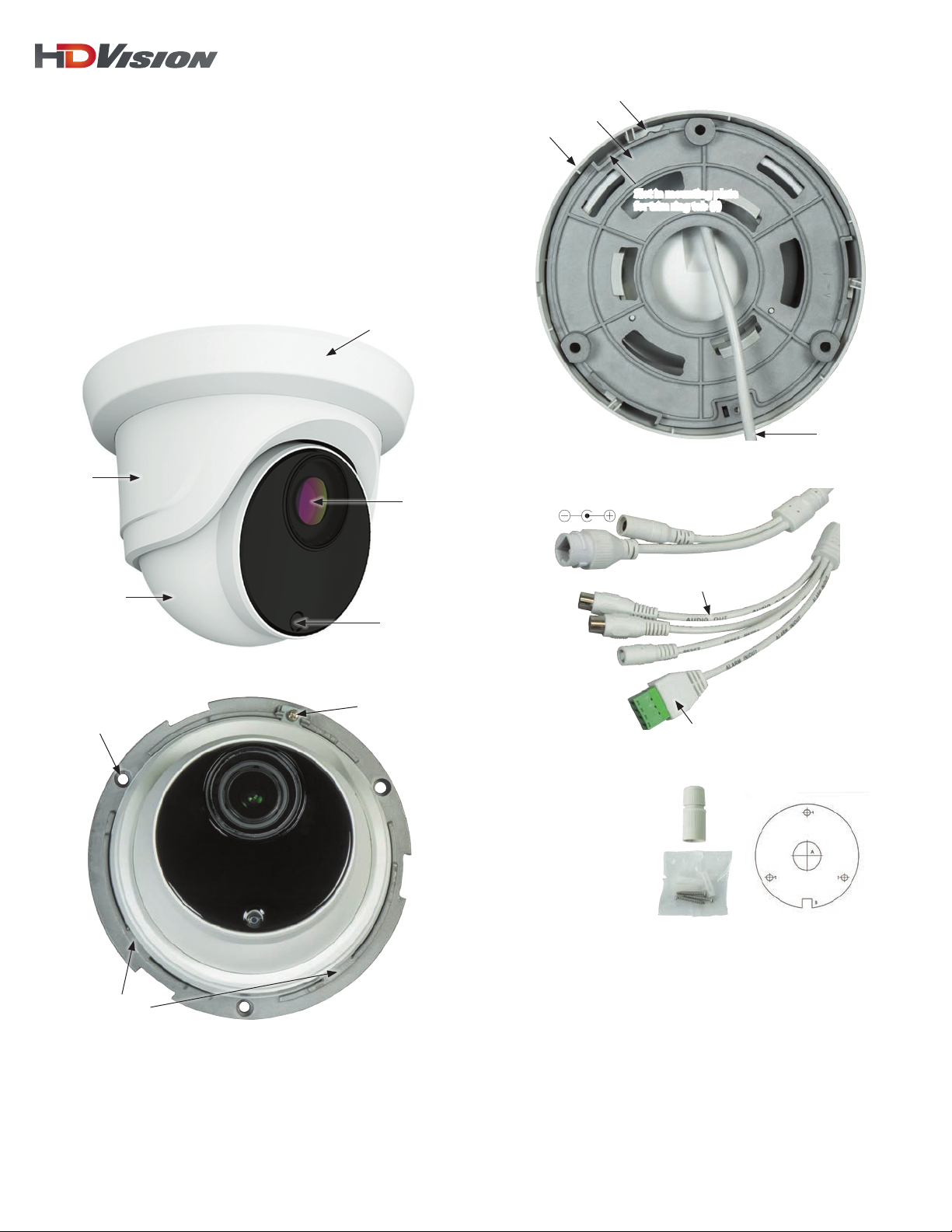
Trim ring
Enclosure
Lens
Turret
Light
sensor
R8VTPS camera assembly
Mounting plate
Trim ring
12 Vdc Power connec tor
Ethernet
connector
(with PoE )
Trim ring tab (3)
Slot in mounting plate
for trim ring tab (3)
Drop cable
Mounting side of mounting plate
Cables labeled for function
Reset button*
1
Holes for
mounting
screws (3)
Tabs (2) hold
enclosure
Camera (turret assembly without trim ring) top view
www.observint.com
Clip plate
and screw
Terminal functions
* To reset the cam era, press an d hold down the Re set button fo r ten seconds wh ile the camera i s powering on.
Camera d rop cables
What’s in the box
• Camera assembly
• Waterproof Ethernet connec tor
• Mounting hardware
• Securit y L-wrench
• Drill template
• Quick Installation Guide
Tools you need
To install the camera, you will need:
• 12 Vdc power source or Ethernet PoE injector. See Specications for wattage requirement.
• Tools and additional fasteners (may be required) for mounting the c amera
• Phillips #2 screwdriver
• Ethernet drop c able
• 12 Vdc power extension cable (if powering with 12 Vdc supply)
Installation
Before installation:
• Make sure that the device is in good condition and all the assembly par ts are included.
• Check the spe cication of the products for the installation environment.
• Make sure that the wall or the ceiling is strong enough to withstand 3 t imes the weight of the camera.
HDV_ R8VTPS_ CQ
190630
Page 2
• To avoid re or shock hazard, use only UL listed power supplies. Verify that the power supply will
CAUTION
provide the rated voltage and wat tage for the camera. See the Sp ecications section.
Step 1. Mounting the camera
A R8VTPS camera can be mounted directly to a wall or ceiling. T he surface should suppor t at least three
times the weight of the camera. The drop c ables of this camera are normally routed through mounting
surface.
1. Acquire the kind of fasteners that will work best for mounting the camera to the ceiling or wall. The
mounting hardware provided with the camera will work well wi th many types of surfaces.
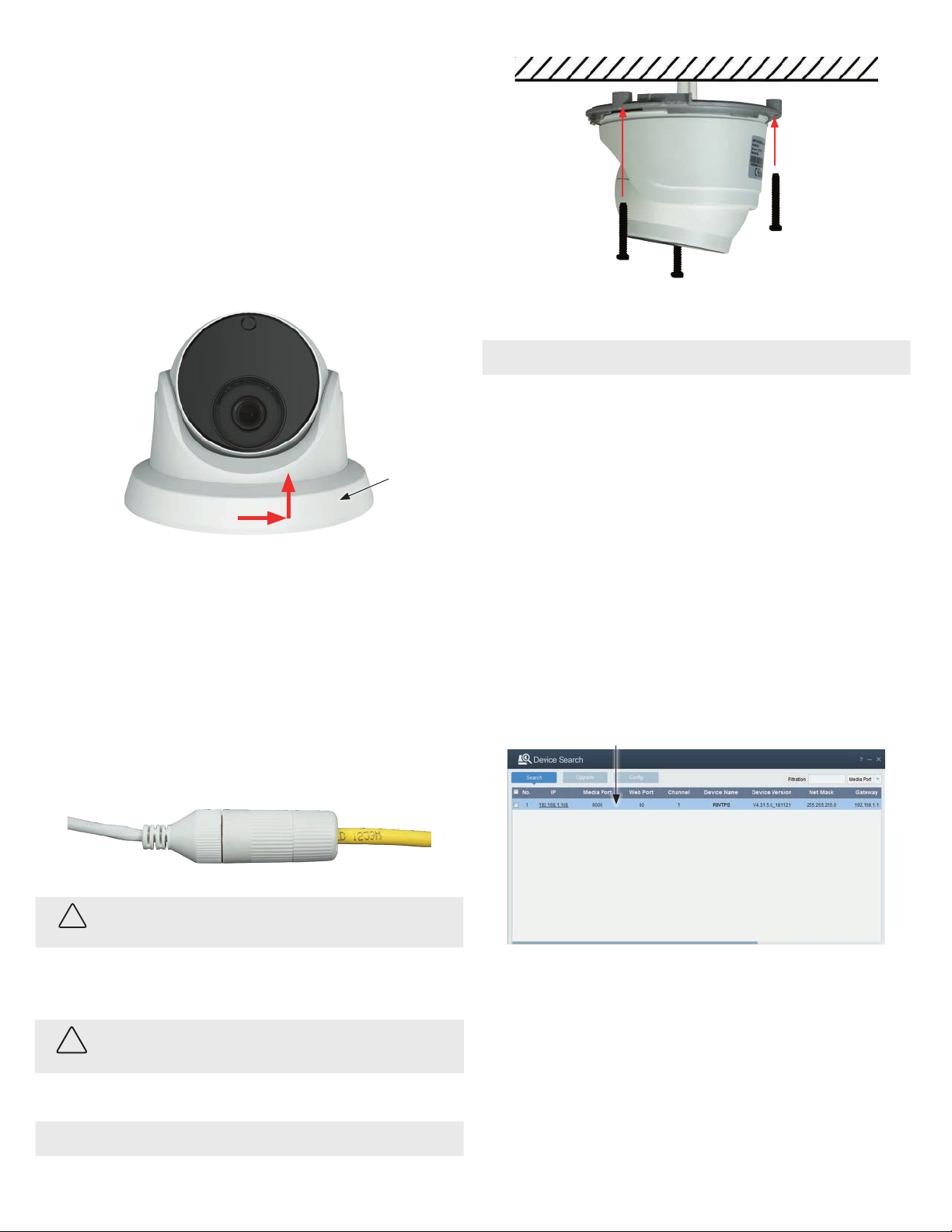
2. Remove the trim ring:
a. Inspect the mounting side of the mount ing plate to see how the trim ring lock s onto it.
b. Set the camera mounting plate down.
7. For outdoor ins tallations, seal holes drilled in the mounting surf ace to block moisture and other
contaminants, if ne cessary.
Trim ring
c. Rotate the tr im ring to the right about 15° counterclock wise, and then lift it of f.
3. Using the camera or the template provided, mark the locations of the mounting screw holes, and a
3/4” hole for the drop cables. Drill holes in the sur face of the mounting location to accommodate the
camera fas teners and the drop cables.
4. Route the Ethernet, power (if not using PoE), audio and alarm ex tension cables from those
peripheral devices to the camera mounting location and out through the hole drilled for the c amera
drop cables.
5. Connect the Ethernet, power, audio and alarm ex tension cables to the camera drop cables:
a. Connect the audio and alarm extension cables to the per ipheral devices as needed.
b. Connect the Ethernet c able to the camera LAN drop cable. Protect the conne ction from
moisture and other contamination, if ne cessary. A Weatherproof Ethernet F itting is provided.
Installation ins tructions for the t ting are at the end of this document .
NOTE
Do not reinstall the t rim ring at this time.
8. Apply power to the camera through the 12 Vdc power cable or PoE injector, as congured.
Step 2. Use the Device Configuration Tool software to
configure network settings
NOTE: Skip this Step if y ou are adding your camera directly to th e Ethernet connectors on the ba ckpanel if an NVR.
Installation
The Device Conguration Tool is a PC-based network utility for discovery of your net work camera for your
N-series recorder. It provides an easy way to congure the camera’s network set tings and reset the camera.
It can be installed on a Microsof t® Windows® (Windows 7 or newer) operating sy stem that has access to
the networ k where your the cameras are installed. The Device Conguration Tool is available from your
vendor.
1. Acquire the Device Conguration Tool from your vendor. At the time when this document was
published, the le is named: Device Cong Tool_<version>.exe.
2. Run the .exe le on a Windows computer that is connec ted to the LAN where your cameras are
installed. Follow the on-screen instruc tions to complete the installation. You may have to open
ports in your rewall. The sof tware automatically opens after it is installed and then searches for
compatible camer as on the LAN. See below.
Click here to vi ew network set tings
Networ k drop cable
!
WARNING
from camera
Drop ca ble connect ors are not wate rproof. Failure of t he power or Etherne t
connecto r due to moisture or a nother contami nant is considere d an installati on
error, which voi ds the warranty. Seal a ll connection s adequately.
Weatherproof Ethernet Fitting installed
Networ k cable from
router or s witch
c. If the camer a is not powered using PoE (Power over Ethernet inje ctor), connect the 12 Vdc
power extension cable to the camera power drop cable. The polarity of t he drop cable
connector is shown in the drop cable photo above.
Do not apply p ower to the camera at this time. Before applyin g power through a power extensi on
cable, ensure that the pol arity is correct. An incorrect connec tion may cause a malfunctio n and
can damage the cam era.
6. Route the drop cable through the hole in the mounting surface, then at tach the camera assembly to
the surface using the appropriate fasteners.
NOTE
2 www.observint.com
Make sure the Reset but ton (drop cable) is accessible after mounting th e camera, if necessary.
Modify network settings
Modify the network settings of t he camera you are installing to avoid IP address conicts on the LAN. Verif y
that the your new se ttings will be compatible wit h other devices on the networ k before continuing. Consult
with your net work administrator for spe cic recommendations, if necessary.
3. Click the entry in the search results list for the camera you are installing. The f rame at the bottom of
the window shows User Info (UserName and Password) and Device Info (network settings).
4. Enter the new and compatible network set tings in the Device Info eld (see below). Here, the IP
address was changed to 192.168.0.68, and the Gateway was changed to 19 2.16 8.0 .1.
© 2019 Observint Technologies. All rights reser ved.
Page 3
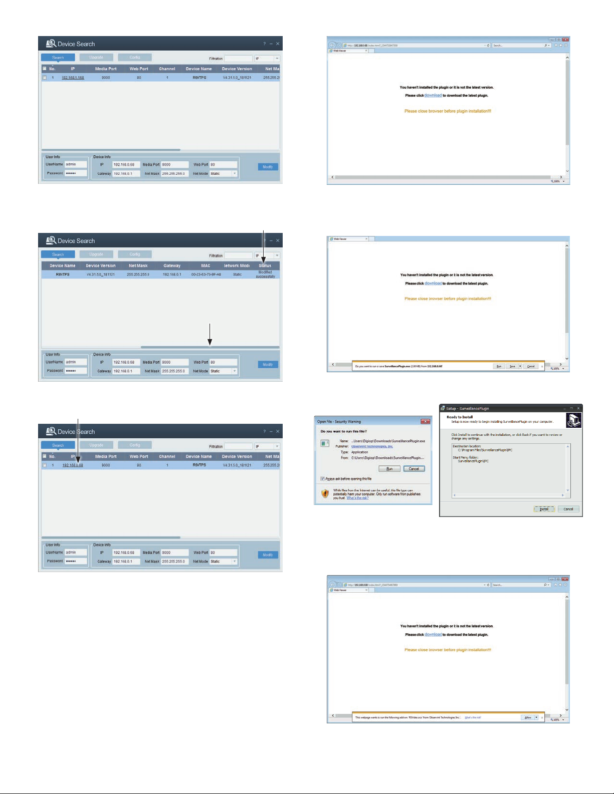
5. Click Modify, and then slide the Shif t Bar to the right. The St atus of the modify operation is
shown in the right-most column.
Modify status
Shift b ar
2. In the screen above, click the download hyperlink.
3. In the following window, click Run in the footer menu, and then c lose your browser.
6. Slide the Shift Bar to the left to se e the new settings in the Searc h list.
Click here to lo gin
Step 3. Perform the initial setup of the camera
NOTE: Skip this Step if y ou are adding your camera directly to th e Ethernet connectors on the ba ckpanel if an NVR.
1. To log into the camera and setup a password, click on the IP address of the camera in the list you
want to log into (see above). If SurveillancePlugin was not previously installed on your computer, the
following window will appear. You must install the plugin to access the camera.
4. Follow the on-screen instructions to complete the ins tallation o SurveillancePlugin.exe.
5. Return to the Device Conguration Tool menu, and then click on the IP address of the camera
you want to log into.
6. If the follow screen appear s, click (select) Allow in the footer query.
3
www.observint.com
7. Next, the browser will appear with a Password popup window. Use this feature to s etup a unique
password for your camera. Enter a password in the Password and Conrm elds that indicates a
© 2019 Observint Technologies. All rights reser ved.
Page 4
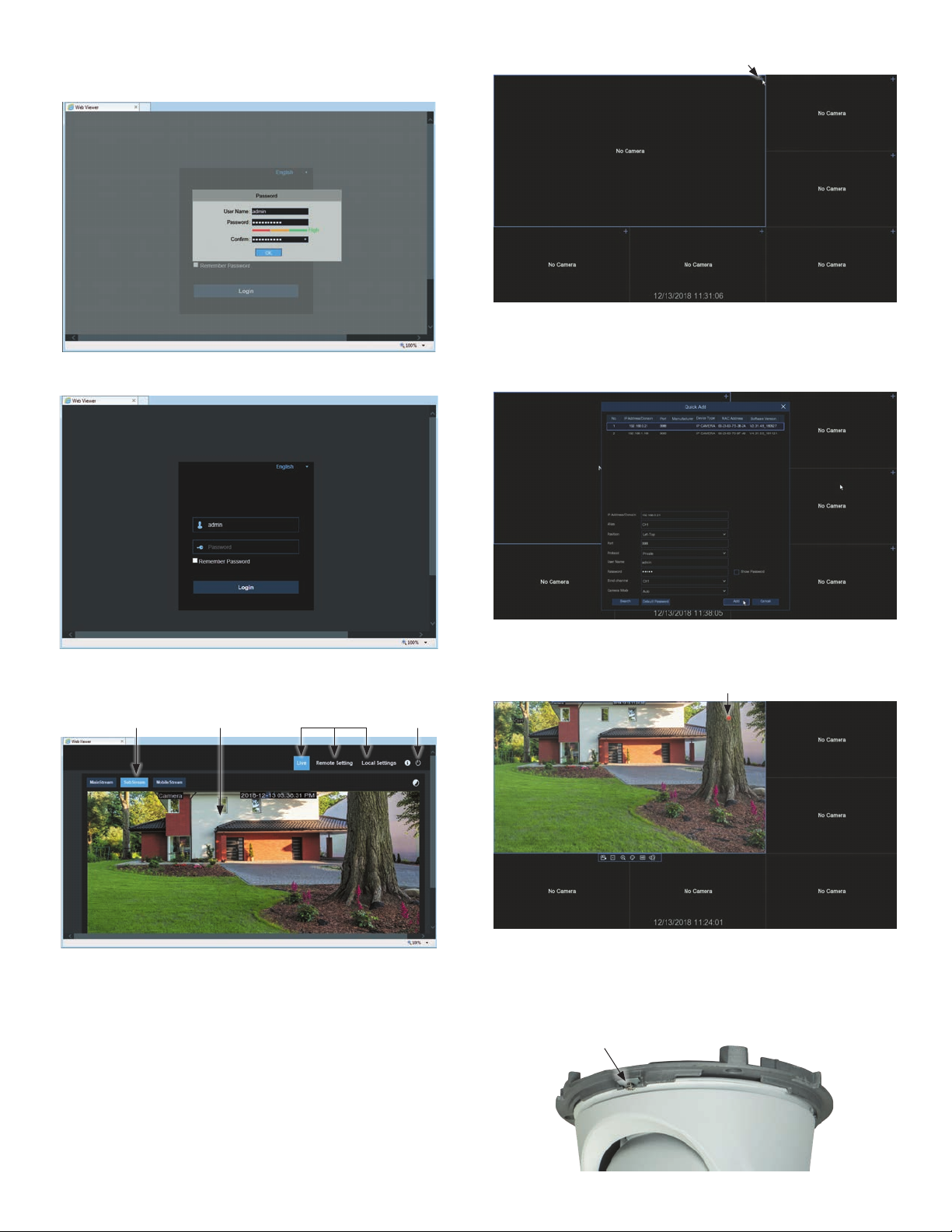
High security level as shown below, and then click OK. Copy the new password for the c amera and
save it in a safe place.
8. In the Login screen shown below using the new password you created previously.
Click to add camera
1. To add a camera to a frame, click the + icon in the upper right corner.
2. In the Quick Add menu that opens, a list of cameras that can be added appears at the top. Click on
the one you want to add to the viewing frame.
Following a success ful login, the camera live view window will appear. Notice that SubStream is
shown by default . Click MainStream to see a bet ter image.
Click here to LogoutScreen selectLive view imageStream select
9. Exercise the motorized zoom f eature of your camera using the PTZ menus in the remote connec tion
interface.
Step 4. Using the NVR Live View screen - add camera
NOTE: Skip this Step if y ou are adding your camera to an IP net work.
If you are adding your camera directly to the NVR backpanel Ethernet connec tors, use this step.
3. Check the parameter s in the menu to ensure they are correc t (see above), and then click the Add
button. Video from the camera will appear in the vie wing frame.
Status Icons
Refer to the User Manual for your NVR for additional information about using your camera.
Camera adjustments
1. Loosen the clip plate s crew enough loosen the enclosure from the mounting plate and to allow the
turret to be aime d at your target. Do not remove the clip plate screw.
Clip plate and screw
4
www.observint.com
© 2019 Observint Technologies. All rights reser ved.
Page 5
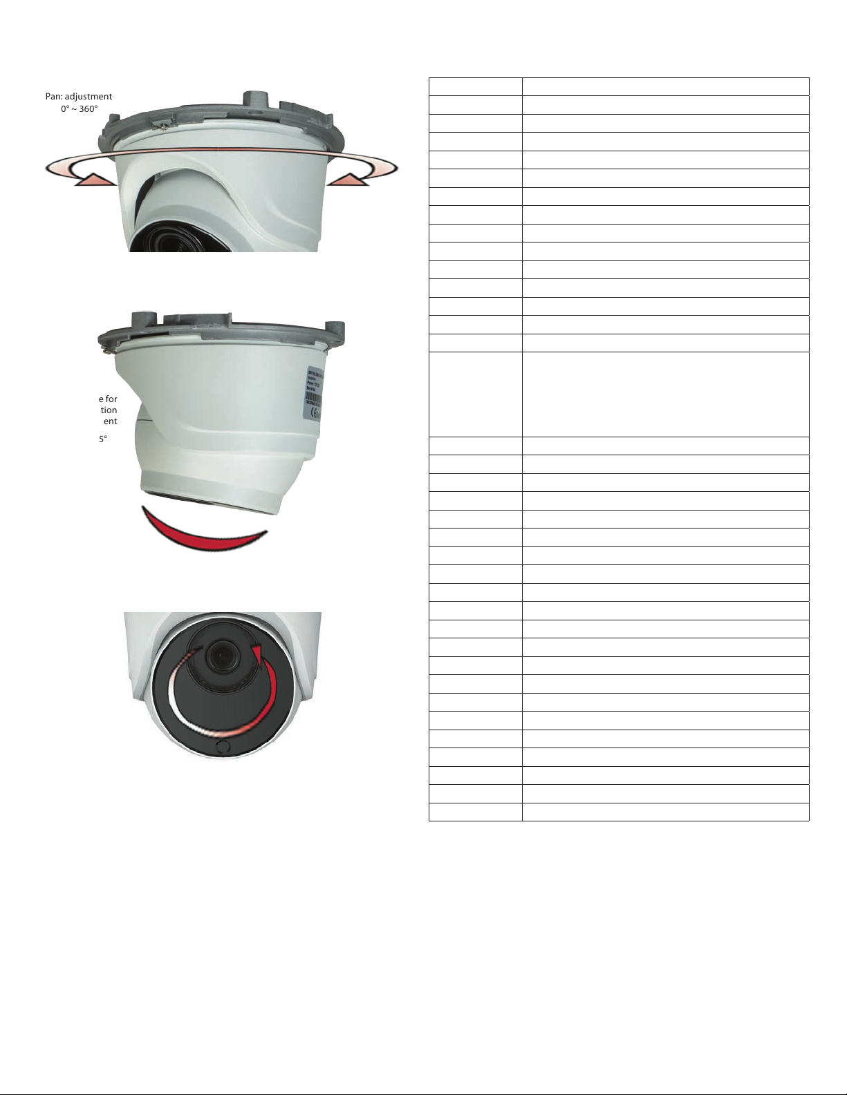
2. Pan adjustment: While observing video f rom the camera, rotate the enclosure with the turret to
point the camera in the direction of your surveillance target.
Pan: adjustment
0° ~ 360°
3. Tilt adjustment: Turn the camera turret assembly within the enclosure to point it at the center of
your surveillance target.
Tilt: Use for
elevation
adjustment
0° ~ 75°
4. Rotation adjustment: Rotate the camera turret assemb ly within the enclosure to align the
camera with the horizon in the eld of view.
Rotation adjustment
0° ~ 360°
5. Use the recorder console or web interface to adjust the zoom.
6. Make additional pan, tilt and/or rotation adjustments using the steps above as needed to per fect the
camera eld of view.
7. Tighten the clip plate screw to hold the turret in position.
8. Reinstall the trim ring.
Step 5. Additional Setup procedures
Refer to the User Manual for your camera for proce dures to customize your camera for your surveillance
application.
Specications
Model R8VTPS
Resolution 3840 (H) × 2160 ( V), 8MP
Image sensor 1/2.5” Progressive CMOS sensor
Min. illumination Color 0.1 lux @ F1.2 (AGC ON); B/W 0 lu x @ IR ON
Shutter 1/5 ~ 1/20000s
Slow shutter Supported
Lens 3.3 ~ 12 mm (Motoriz ed), horizonta l FOV: 105 ~ 37°
3-axis adjustment Pan: 0 ~ 360°, tilt: 0 ~ 75°, rota te: 0 ~ 360°
F No. F No. wide: 1.4 ~ tele: 2.8 ± 5%
Day & Night IR cut lte r with auto swi tch
Digital noise reduction: 3D-DNR
WDR 120 dB
Video compression H.265 / H.264
Video bit rate 8 Kbps ~ 16 Mbps
Triple Str eam Yes
Main Stream: (1 ~ 30 fps, defaul t 30 fps)
8 MP (3840 × 2160), 5 MP (307 2 × 1728, 2592 × 1944), 4 MP (2592 × 1520),
Resolution
Image settings: Flip, Rotat ion, Saturat ion, Brightne ss, Contras t, Hue, Sharpne ss adjustabl e
BLC Supported
ROI Supported
Privacy mask Supported
Protocols TCP/IP, HTTP, DHCP, DNS, DDNS, RTP/RTSP, PPPoE, SMTP, NTP, UPnP, SNMP, HTTPS, FT P,
System compatibility ONVIF (Prole S, Prole G)
Interface 1 × RJ45 10M / 100 M Ethernet inte rface
Led 40 pcs (SM D)
IR range Up to 150 ft (45 m)
Alarm triggers 1 × input , 1 × out put
Audio 1 × input / 1 × out put (RCA)
Video output Ye s
Reset button Yes
PoE Yes
Ratings IP66 (weatherproof)
Power supply 12 Vdc / POE
Consumption ≤ 9 W
Dimension Ø5.35 × 5.04 i n (Ø136 × 128 mm)
Weight 1.59 lb (720 g) appr ox.
Storage temperature -22° ~ +140°F (-30° ~ +6 0°C)
Operating temperature -22° ~ +131°F (-30° ~ +55°C)
3 MP (2304 × 1296), 108 0P (1920 × 1080), 720P (1280 × 720)
Sub Steam (1 ~ 30 fps, default 15 f ps)
1080P (1920 × 1080), 720P (1280 × 720), VGA (6 40 × 480), QVGA (320 × 240)
Mobile Stream (1 ~ 30 fps, default 10 f ps)
VGA (640 × 4 80), QVGA (320 × 240)
Cleaning
Clean the camera with an approved glass cleaning solution and a lint f ree cloth.
• Dust can be removed from the unit by wiping it with a sof t damp cloth. To remove stains, gently rub
the surface with a sof t cloth moistened with a mild detergent solution, then r inse and dry it with a
soft clot h. Do not use benzene, thinner or other chemical product s on the camera assembly; these
may dissolve the paint and promote damage of the sur faces.
• Remove all foreign par ticles, such as plastic or rubber materials, at tached to the camera housing.
These may cause damage to the surf ace over time.
5
www.observint.com
© 2019 Observint Technologies. All rights reser ved.
Page 6
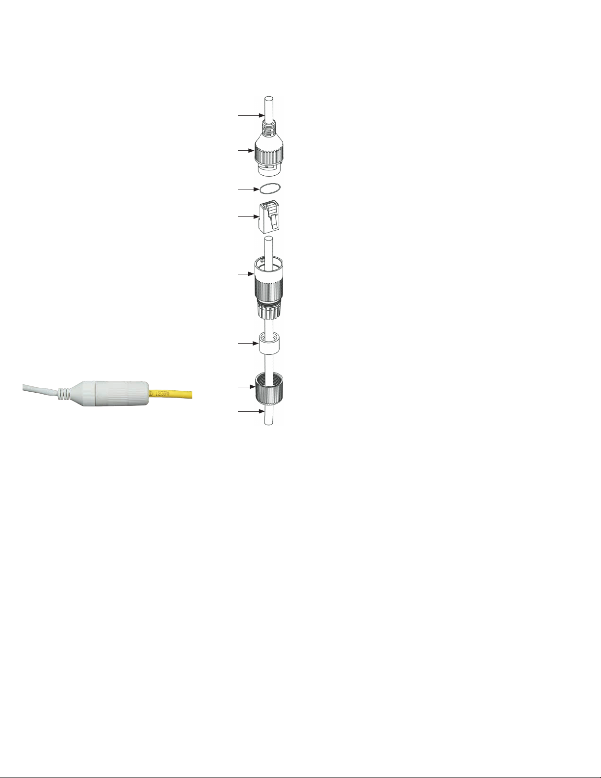
Using the Waterproof Ethernet Fitting
Install the Waterproof Ethernet Fitting on the Ethernet cable end at the camera w hen moisture or
contamination ex ists in the area near the camera. The tting includes several par ts that must be installed in
a specic order. To install the tting:
1. Place the rubber O -ring over the camera drop cable end c ap.
Push the O-ring up to the connector cap.
2. If the ne twork cable from the switch or router has a connector
on the end, cut o the connector.
3. Place the Lock Nut onto the net work cable from the router
or switch as shown in the drawing to the right. The inside
threads must be toward the camera end.
4. Place the r ubber basket onto the networ k cable above the lock
nut as shown.
5. Place the end cap onto the net work cable above the rubber
gasket as shown. The ngered end must be toward the router
or switch.
6. Inst all an RJ-45 connector onto the network c able.
7. Plug the RJ- 45 connector with the net work cable into the
camera net work drop cable.
8. Fit the end cap on the net work cable onto the camera drop
cable end cap. Rotate the network cable end cap to lock it in
place.
9. Push the rubber gasket fully into the end of the network cable
end cap.
10. Screw the lock nut onto the network cable end cap until it is
fully seated.
Networ k drop
cable fro m
camera
Drop cable
end cap
Rubber
O-ring
seal
RJ- 45
connector
End cap
Rubber
gasket
Networ k drop
cable fro m
camera
Ethernet Fitting installed
Waterproof Ethernet Fitting assembled and connected
Networ k cable from
router or s witch
Lock nut
Networ k
cable
from
router or
switch
6
www.observint.com
© 2019 Observint Technologies. All rights reser ved.
 Loading...