


1
RS_R4-8-16_SQ
181220
1
9 11
47532
6 8
R8 backpanel
1 2
9 10
4
75
3
6
8
R16 backpanel
Item Description
1 AUDIO IN RCA connec tor for audio in c able
2 VIDEO INPUT BNC connec tors for cam era video chann els in
3 VGA Connecto r VGA monitor cab le.
4 RS-485 terminations
Connecto r for RS-4 85 devices. Conn ect the D+ and D - terminals to T+ and T- of PT Z receiver resp ectively.
(+, –) pins connect to R+ and R- p ins of PTZ receive r respect ively. For casca ding devices, t he rst DVR’s +, – pins shoul d be
connecte d with the +, – pin of the ne xt DVR.
5 AUDIO Out RCA connec tor for audio o ut cable.
6 HDMI Connector HD MI monitor cabl e.
7 LAN RJ-45 c onnector fo r Ethernet dro p cable.
8 USB USB (3.0) fo r a USB mouse or USB memo ry device suc h as a ash drive or DVD d rive. A USB por t is also locate d on the front pan el.
9 12 Vdc Plug for 12 Vdc power ad apter (provide d).
10 Ground Ground term inal. Connect t o earth groun d.
11 Switch ON / OFF switc h
Mouse control
A standard 3-but ton (left / right / scroll-w heel) USB mouse can also be used wit h this DVR. To use a USB mouse:
1. Plug the USB mouse into the eit her the front panel or back panel USB conn ector of the DVR.
2. When the recorder is powered on, the mo use will be automatically detec ted. If the mouse is not detec ted, the mouse may not be
compatible with the DVR . Please refer to the recommended d evice list from your provider.
This guide provides ins tructions to initially se tup the R16 (16 channel) digital vid eo recorders (DVR). The DVR supports t hese advanced
features:
• Self-adaptive HD-TVI / HD -CVI / AHD / CVBS video input
• Support camer a resolution up to 8 MP video input an d live view
H.264/H.265 Video encoding
• Supports HD Ds up to 8TB. See specication s.
• Simultaneous HDMI / VGA moni tor output
• Up to 16-channel synchr onous playback
• Supports HDVision mobile app for iOS and Android
• DDNS, PoE and P2P remote connect ivity
DVR Front Panel
USB Interface
Power LED HDD in use
R4, R8 front panel
USB Interface
Power LED HDD in use
R16 front panel
Item Usage
Power LED Indicator turn s green when DVR is p owered up.
HDD in use Indicator t urns red when HD D is reading / writ ing.
USB Interface T his port can b e used for a USB mou se or USB ash memor y devices.
DVR Back panel
12
9
4
75
3
6 8
R4 backpanel
R4, R8, R16 Digital Video Recorders Quick Setup Guide
2 www.Observint.com
© 2018 Observint Technolo gies, Inc. All rights re served.
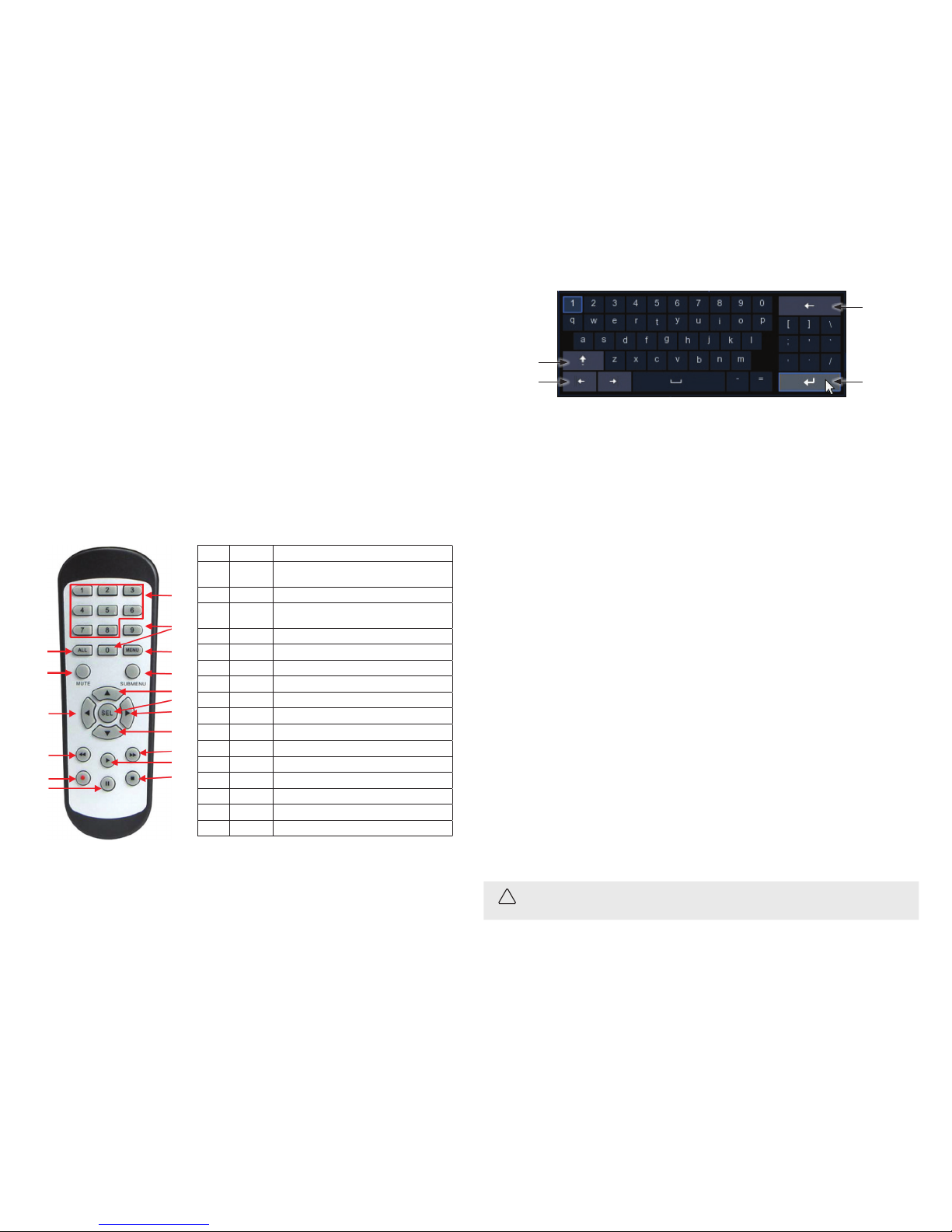
Move cursor
left, rig ht
Enter
Click to
delete
previous
character
Click for
upp er,
lower case
Installing the System
Step 1. Getting Started: Unpacking the Equipment
What’s in the box
Your system includes:
• DVR
• USB mouse
• Power adapter for DVR
• Remote control
Remove the equipment f rom its packaging and place it on a at, c lean surface. Inspect eac h item. If any visible damage is present, conta ct
your supplier for a replacement . Verify that your order is complete.
What you need
Although each secu rity system installat ion is dierent, most require the f ollowing items not included with your s ystem components:
• Cameras and cables co mpatible with the DVR. The VIDEO INPUT conne ctors on the back panel sup port analog cameras. Che ck the
Specications section of this guide for more information.
• IP cameras installe d on the Ethernet network (L AN) associated with the DVR mus t be compatible. Check the Specications sec tion of
this guide for more information.
• Tools to install the cameras an d route power and video cables
• Fasteners to attach t he cameras to the mounting sur faces, calking
• VGA or HDMI compatible computer m onitor to connect to the DVR.
• Un-interuptable powe r supply (UPS) is recommended. This UPS is u sed to ensure system stabili ty during voltage surges, sag s, and
outages. If a UPS is n ot available, a power strip with stro ng surge protection is highly reco mmended.
Step 2. Install the DVR
HDD Installation
If your DVR was purchased w ithout an HDD, or you want to add an additional HDD or rep lace one, follow the guidelines shown here. The HD D
installation should be p erformed before u sing your DVR. For lasting per formance and reliability, install only sec urity grade HDDs in your DVR.
The chassis is designe d to accommodate both 3.5 inch and 2.5 inch HDDs, w ith an HDD capacity up to 8 TB.
CAUTION
Before perform ing this procedure, ensure that the power cord is not disconnec ted from the DVR.
Using the mous e
1. Left But ton:
— Click to select menu o ptions.
— During live viewing in spli t-screen view, double-click on a channel to v iew it in full-screen. Double -click the channel again to
return to split-scre en viewing.
— Click upon a channel on Live V iewing screen to open Camera Quick Toolbar.
— Click and hold to drag slider s and scales on menu mode
2. Right Button:
— Click once to open the task b ar on the Live Viewing screen.
— In menus, click to go back or clo se the menu.
3. Scroll Wheel:
— In menus, scroll to move up / down t hrough the menu content.
— While hovering over the volume cont rol wheel, scroll to turn sys tem volume up / down.
Using the Remote Control
3
5
11
14
16
9
1
6
4
2
10
13
15
12
7
8
9
No. Icon Description
1 1-8
Numeric keys
Press to disp lay channel 1~8
2 9, 0 Numeric keys
3 ALL
Press to disp lay all channels
Multiple dis play mode
4 Menu Press to e nter or exit th e Main Menu
5 Mute Mute On/o
6 Submenu Go to submenu
7
Up arrow key; Volum e increase
8 SEL Press to ente r the selecte d menu item and ed it the setti ng
9
Left/ Right key; Decr ease/increa se parameter v alue of control ba r.
10
Down arrow ke y; Volume decreas e
11
Press to rewi nd during vide o playback
12
Press to fas t forward du ring video play back
13
Press to play re corded vide o or enter the reco rding search men u
14 Press to s tart manual r ecording
15 Press to s top manual reco rding or stop th e video playbac k
16 | | Press to pause the vid eo playback or e nter frame- playback mode
Using the Virtual Keyboard
When you click in an editab le data entry eld, a virtual key board will appear. Click on the character in t he keyboard to enter it into the eld.
When the data entr y is complete, click the Enter key in the lower right cor ner.

3 www.Observint.com
© 2018 Observint Technolo gies, Inc. All rights re served.
CAUTION
Do not apply power to th e DVR at this time.
Step 3. Connect devices to the DVR
Your DVR security sys tem is highly congurable to meet your appli cation requirements. The diagr am below illustrates how the DVR can be
interconnected to var ious devices. Refer to the Specications sec tion for more information a bout the capacity of your DVR .
Analog
Cameras
Network Cameras
Power
adapter
PTZ
Camera
Internet cloud
Monitor
Router
RS485
network
Ethernet
Ethernet
Mouse
or Flash
Media
Router
Speakers
VGA or
HDMI
Microphones
Cameras
Install your secur ity cameras. Always follow t he installation instruc tions provided with the camer a.
1. Install the analog cam eras that will connect to the VIDEO INPUT conn ectors on the back of the DVR .
2. Route video / power extensi on cable(s) between the cameras and th e DVR. Note that power connectors o n some extension cables
are dierent: the pow er connector at the camera is a male s tyle connector, and the power connec tor at the source (usually DVR) is a
female style connec tor.
3. Connect the exten sion cable(s) to the camera and the DVR.
Install a monitor, mouse, microphones, network, power etc
For the following st eps, refer to the back panel photo above f or the location of connector s.
1. Install and setup you r monitor in accordance with the instr uctions provided with t he monitor. Do not power it on at this time.
The example shown here i s for an R16 DVR. To install an HDD:
1. Lay the DVR on a clean, at table, and th en remove the ve cover screws shown in the pic ture below on the left .
2. Slide the cover back, then lift i t o the DVR chassis.
3. Unpackage your HDD(s).
4. Connect a SATA cable and one of the HDD power cables to th e HDD as shown in the picture below on t he left.
5. Position the HDD in the chassis, ali gning the holes in the bottom of th e chassis with the with the mount ing screw holes on the
underside of the HDD.
6. Holding the HDD in place, turn over the DVR with t he HDD, and then use four (4) screws to attach the HD D to the chassis.
7. Lay the DVR on the table, top up. Che ck the to make sure the SATA and power cables are fully seated bot h on the HDD and the chassis
PC board.
8. Install a second HDD if neede d and the chassis has space for it.
9. Reinstall the cover on th e DVR.
Install the DVR
1. Place the DVR in a location that is s ecure, well ventilated and clean. The DVR should be p ositioned such that the back pa nel connectors
are accessible and the ventilat ion holes on the top and sides are not bloc ked.
2. Connect the ground terminal (if availab le) on the back of the DVR to an earth ground. Ref er to local electrical cod es for proper
grounding.

4 www.Observint.com
© 2018 Observint Technolo gies, Inc. All rights re served.
1. In the screen shown ab ove, enter your admin password in the New Admin Password and Conrm Password elds (see below).
Ensure that the Password Strength of your passwo rd is at least Medium (preferably Stron g).
NOTE
If you forget your passwo rd, you will be unable to login the sy stem, please contact your vendor to reset th e password.
2. If you want to use an Unlock Pattern to acces s the conguration menus, open the Unlock Enable drop dow n list, and then click
Enable. Click Apply to continue.
3. Click the Draw button to op en the Set Unlock Pattern window.
4. In the Set Unlock Pattern window, drag the mouse cursor across a p attern of circles, then releas e the mouse.
NOTE
Some monitors have mu ltiple inputs such includ ing VGA ,HDMI, BNC, etc. If you are using th is kind of monitor, congure your monitor to
display the input connec ted to your DVR (HDMI or VGA).
2. Cable the HDMI or VGA connector to yo ur monitor’s HDMI or VGA input. The HDMI inter face provides the best pe rformance.
3. Plug the mouse provided into the USB con nector on the front or back o f the DVR.
4. If using microphones with you r cameras, install the microphon es where needed, and then plug the mi crophone extension cable s into
the AUDIO INPUT RCA connectors on t he back of your DVR.
5. Plug a drop cable from your loc al area network (LAN) router into th e RJ45 LAN connecto r on the back of the DVR.
6. If using speakers, plug your speaker set into th e AUDIO OUT RCA connector on the back of the DVR. Th e AUDIO OUT connector
provides a line level signal ou tput. An audio adapter may be neede d to connect your speaker set to the DVR RC A connector.
7. If using an RS485 n etwork to control a PTZ camer a or other device, cable the RS4 85 terminations on the back of the DVR to your
network. T he DVR must be congured for the RS 485 network you connec t to the DVR and the device(s).
8. Connect the power cord with th e 12 Vdc power adapter, and then connec t the power adapter to the 12 V(DC ) power connector on the
back panel of the DVR, and th en into a UPS (recommended) or surge protec tor.
Power on the system
1. Apply power to your power adapter t o power on the DVR. If the DVR has a power switch, als o set the power switch to on.
2. Apply power to the monitor.
3. Apply power to your cameras and microphones.
4. If using a speaker set, apply power to your sp eakers.
Step 4. Using the Wizard for basic configuration setup
When the DVR powers on, a “SYS TEM INITIALIZING” splash screen normally appears w ithin 3 minutes. An a system ac tivation screen will
appear.
Activation
If it is the rst tim e powering on the recorder, an activatio n screen will appear. You must use this menu to setup an admin pas sword for the
system, and an Unloc k Pattern, if preferred, for qu ickly accessing the conguration menu s if the recorder.

5 www.Observint.com
© 2018 Observint Technolo gies. All rights reser ved.
a. It is preferred to have xed n etwork settings in stead of dynamic settings, howe ver. To change from dy namic network settin gs
to xed settin gs, copy the settings found t hrough DHCP for the Local Connec tion and DNS, uncheck the DHCP sele ct box
near the top of the menu, then re -enter the DHCP Local Connec tion and DNS settings. You can also enter your o wn network
settings fo r the recorder (these must be compa tible with other devices on the L AN). If you choose to enter your own networ k
parameters, conside r the following:
IP Address: The IP add ress identies the DVR in the net work. It consists of four g roups of numbers between 0 to 2 55,
separated by perio ds. For example, “192.168.001.100”.
Subnet Mask: Subnet mask is a netwo rk parameter which denes a rang e of IP addresses that can be use d in a network. If IP
address is like a stree t where you live then subnet mask is like a neighbor hood. The subnet address also con sists of four groups
of numbers, separate d by periods. For example, “255.255.000.0 00”.
Gateway: This addre ss allows the DVR to access the Internet. T he format of the Gateway address is th e same as the IP Address.
For e xample, “192 .168.0 01.001”.
DNS1/DNS2: DNS1 is the primary DNS ser ver and DNS2 is a backup DNS server. Usually should be enou gh just to enter the
DNS1 server address.
b. You can also congure the ports the DVR . If you need to change the port n umbers of your DVR, consider the following:
Web Port: This is the port that you w ill use to log in remotely to the DVR (e.g. using the Web Client). If the default por t 80 is
already taken by other applicat ions, please change it.
Client Port: This is the port tha t the DVR will use to send information thro ugh (e.g. using the mobile app). If the default port
9000 is already taken by o ther applications, please change it .
RTSP Port: This is the por t that the DVR will be allowed to transmit real-tim e streaming to other device (e.g. using a streaming
Media player.).
HTTPS: HTTPS is the s ecure version of HTTP, the protocol over which data is sen t between your browser and the w ebsite that
you are connected to. If y ou want to log in remotely to the NVR using Web Client, you nee d to complete the port for warding in
your router. The default po rt number is 0443.
5. Repeat the pattern you ente red, and then click Apply to save the congurat ion. The conguration Wizard initial scre en will open.
Using the Wizard for initial conguration
Use the Wizard to set up the basic conguration of your sys tem. Advanced conguration option s are available in the Setup menus. Refer to
the rmware user manual (to be pro vided) for your recorder for more i nformation.
1. When the initial Wizard window appea rs, click Start Wizard to continue.
2. The next Wizard scre en is used to congure the networ k settings of the recorder. Initially, the reco rder acquires network using DHC P
(Dynamic Host Congur ation Processor) which usually exi sts somewhere on your LAN . DHCP provides network se ttings that are
compatible with othe r devices on your LAN.

6 www.Observint.com
© 2018 Observint Technolo gies. All rights reser ved.
If changing the DST set tings, consider the following:
DST: Enable if Daylight Saving Time (DST) i s observed in your region.
Time Oset: Select th e amount of time to oset for DST
Time Mode: Choose to set the daylight s aving time in weeks or in days
Start Time/End Time: Set the start tim e and end time for daylight saving.
4. Click Next to continue.
5. In the Disk menu, you can congure how your di sk (HDD) will be used. The Overwrite (Auto) feature enables you to alway s keep
a previous, optional numb er of days of data written to the HDD w hen the disk becomes full, and Format ini tializes the HDD for use
in the recorder and eras es all data on the disk. If you installe d HDDs in your recorder, it is strongly advised to format these drives
before using your re corder.
a. To congure the HDD for Overwr ite:
i. Check the s elect box for the HDD you want to cong ure from the list above.
ii. O pen the Overwrite drop down list, and then sele ct Auto.
PPPoE: PPPoE is an advanced proto col that allows the DVR to connect to the net work more directly via DSL m odem. Check the
Enable PPPOE box , and then enter the User name and Password of t he PPPoE.
c. Click Next to conti nue.
3. Use the Date/Time menu to set the Date, Time, Date For mat, Time Format, Time Zone, NTP and DS T (daylight savings time).
a. When changing parameter s in the Date and Time tab, consider the fo llowing:
Date: Click on the calendar icon to s et the system date.
Time: Click to set the syste m time.
Date Format: Choos e from the drop down menu to set pref erred date format.
Time Format: Choose time format b etween 24-hour and 12-hour.
Time Zone: Set the correct tim e zone.
b. Click the NTP tab. To use a Network Time ser ver to automatically set the date and tim e in your recorder, check the Enable NTP
box, and then selec t a Server Address from the drop down list. Click Upd ate Now to acquire the current Date and Time
information.
c. Click the DST (Daylight Savin gs Time) tab. Setup the values in the DST menu to ma tch your local DST custom, if prefe rred.

7 www.Observint.com
© 2018 Observint Technolo gies. All rights reser ved.
10. In the Summary screen, you can:
— Check the selec t box to Don’t show this window next time.
— Click Previous to return to the Wi zard screens and change your selec tions.
— Click Finish to close the Wizar d.
11. C lick Finish to close the Wizard.
Step 5. Using the Live View screen
Task Menu Bar
Start Menu
Quick Setting Toolbar
Camera Title
System Date / Time
Status Icons
b. To format an HDD:
i. Check the s elect box for the HDD you want to Fo rmat from the list above.
ii. C lick the Format button. Allow the format ope ration to complete before continuing.
6. Click Next to continue.
Use the Resolution menu to selec t an output resolution that ma tches your monitor. The DVR automatically adjust s the output resolutio n
during star t up to match the highest resolutio n of your monitor.
7. To change the resolution, ope n the drop down list, select t he resolution you prefer, and then click App ly.
8. Click Next to continue.
The Mobile screen sho ws the P2P settings provided w ith your recorder, and a QR code you can scan to easily conn ect the DVR to the mobile
app HDVision (available free f or Android and iOS).
9. Click Next to continue.
The Summary screen shows t he settings selecte d the Wizard.

8 www.Observint.com
© 2018 Observint Technolo gies. All rights reser ved.
• Task Menu Bar
To open the Task Menu Bar, click the right mou se button anywhere in the L ive View screen.
Screen layout n x n
Open Start m enu
Information
available Layout options
Network
disconnected
Manual Record or Alarm
start / sto p
View channel
sequence
Quick
playback *
Adjust volume
* Quick playback: Click to playback all channels from s tart of day or playback last 5 s, 10 s, 30 s, 1 min, 5 min.
• Setup (Menu mode)
To open the Setup menus, click the icon in the lower r ight corner of the Task Menu Bar, and then click the Setup icon. Click the blo ck
for the setup cong uration you want to see or change. Using the se menus may require authenticati on.
Refer to the DVR User Ma nual for more information abou t the setup features of your reco rder.
Specications
Model R4 R8 R16
Video Compression H.265 / H.264
Video Syste m NTSC / PAL
Operation System Linux (embedded)
Analog video-input /
output
4 channel inpu ts / VGA and HDMI ou tput 8 channel inpu ts / VGA and HDMI ou tput 16 channel input s / VGA and HDMI out put
Audio input / ou tput 4 channel input s / 1 channel outpu t (RCA)
Display resolution
4K Model: Analog : 8MP: 15 fps,
5MP: 20 fps,
4MP / 3MP / 1080P / 72 0P / 960H: 30 fps
5MP Model: Analog: 5MP: 20 fps,
4MP / 3MP: 30 fps ,
1080P / 720P / 96 0H
IP: 4MP / 3 MP / 1080P / 72 0P
4K Model: Analog : 8MP: 15 fps,
5MP: 20 fps,
4MP / 3MP / 1080P / 72 0P / 960H: 30 fps
5MP Model: Analog :5MP: 20 fps,
4MP / 3MP: 30 fps , 1080P / 720P / 960 H
The Live View scree n includes several useful feat ures:
• Camera Title
— A-: This indicates that the c amera connected is an AHD camera
— T-: This indicates that the camer a connected is a TVI camera
— C-: This indicates t hat the camera connected is a C VI camera
• Status Icons
This indicates that the DVR is currently recording.
This icon app ears when the ca mera has detec ted motion.
The icon indic ates that the e xternal I/O alar m device is tri ggered
This icon indi cates that the H DD is in error to wor k
This icon indicates the HDD is unformatted
This icon indi cates the HDD is f ull.
This icon indi cates the HDD is r ead-only.
• Camera Quick Setting Toolbar
Play last 5 min. reco rdedRecord start/stop Zoom*
PTZ control p anelCapture snapshot Adjust color
* ZOOM: Click to zoom-in on t he channel. When the zoom icon appears, pre ss and hold the left mouse b utton, then drag across the
area you want expand.
• Start Menu
Click to switch user or en able multi-user.
Click for search and playbac k.
Click to Setup the system (enter menu mo de).
Click to Lock / Unlock the sc reen.
Click to Shutdown, Reboot and Lo g out of the system.
NOTE
If the recorder is not in menu operatio n for one (1) minute, the screen will lock to prevent unauthorized OSD op erations.

9 www.Observint.com
© 2018 Observint Technolo gies. All rights reser ved.
Model R4 R8 R16
Display feature 1 / 4 / 6 / S.E.Q 1 / 4 / 6 / 8 / 9 S.E.Q 1 / 4 / 6 / 8 / 9 / 10 / 13 / 14 / 16 / S.E.Q.
Record resolution
Analog: 8MP / 5MP / 4MP / 3MP / 1080 P
/ 720P / 960H
IP: 4MP / 3MP / 1080P / 72 0P
Analog: 8MP / 5MP / 4MP / 3MP / 1080 P / 720P / 960H
Record speed
4K Model: Analog: 8MP: 6 fps (eac h ch),
5MP: 8 fps (each ch),
4MP: 10 fps (each c h),
3MP: 12 fps (each ch),
1080P: PAL: 25 f ps (each ch), NTSC: 30
fps (ea ch ch)
5MP Model: Analog: 5MP: 12 fps
(each c h),
4MP: 15 fps (each c h),
3MP: 20 fps (each c h),
1080P: PAL: 25 f ps (each ch), NTSC: 30
fps (ea ch ch)
4K Model: Analog: 8MP: 7 fps (eac h ch),
5MP: 10 fps (each ch),
4MP: 15 fps (each c h),
3MP: 17 fps (each ch),
1080P: PAL: 25 f ps (each ch) / NTSC: 30
fps (ea ch ch)
5MP Model: Analog: 5MP: 13 fps
(each c h),
4MP: 16 fps (each c h),
3MP: 20 fps (each c h),
1080P: PAL: 25 f ps (each ch) / NTSC: 30
fps (ea ch ch)
Maximum output
bandwidth
48Mbps 96Mbps 128Mb ps
Maximum de code
performance
4K Model: 8MP: 12 fps, max 2 ch playb ack
5MP: 32 fps, max 4 c h playback
4MP: 40 fp s
3MP: 48 fps
1080P: 120 fps
5MP Model: max 4 ch playback
5MP: 48 fps
4MP: 60 fp s
1080P: 120 fps
4K Model: 8MP: 28 fps, max 4 ch pl ayback
5MP: 80 fps ma x 8 ch playback
4MP: 120 fps
3MP: 136 fps
1080P: 240 fp s
5MP Model: max 8 ch playback
5MP: 104 fps
4MP: 136 fps
3MP: 184 fps
1080P: 240 fp s
4K Model: 8MP: 56 fps, max 8 ch
playback
5MP: 160 fps max 16 c h playback
4MP: 240 fps
3MP: 272 fps
1080P: 480 fps
5MP Model: max 16 ch playback
5MP: 208 fps
4MP: 256 fp s
3MP: 320 fps
1080P: 480 fps
Recording Mode Continuous / M anual / Motion de tect
Synchronous Playback 3 channels 8 channels 16 channels
Network Type LAN, DHCP, and DDNS
HDD interface 1 × SATA 3.0 HDDs, up to 8TB 1 × SATA 3.0 HDD, up to 8TB
2 × SATA 3.0 HDDs, up to 16TB (8TB
max. each)
Multiplex Operation Live d isplay, record, play back, backup a nd network
USB 1 × USB (for mouse a nd backup / upgr ade)
1 × USB 3.0, 1 × USB 2.0 (for mou se and
backup / upgrade)
1 x USB 3.0, 1 x USB 2.0 (for mou se and
backup / upgrade)
Sensor & Alar m I / O No
PTZ Control Yes (R S4 85)
Mobile surveillance Support s HDVision mobile app f or iPhone and And roid operati on system
VGA / HDMI 1024 × 768, 1280 × 720, 1280 × 1024, 1440 × 90 0, 1920 × 1080 (1080P), 2560 × 144 0 (2K), 3840 × 2160 (4K)
Power Supply 12 Vdc / 2 A 12 Vdc / 5 A
Dimension( W x D x H) 11.8 × 8.94 × 2.1 in (300 × 227 × 53 mm)
14.9 × 13.4 × 2.0 in
(378 × 340 × 50 mm)
Working Temperature -22° ~ +131°F (-30° ~ +55° C) -22 ° ~ +131°F (-30° ~ +55° C) -22 ° ~ +131°F (-30° ~ +55° C)
Working Humidity 10% ~ 90% 10% ~ 90% 10% ~ 90%
 Loading...