

`
HDT –Tactical Systems Business Unit
30525 Aurora Rd
Solon, Ohio 44139-2795
Tech Support: (800) 684-6111
www.hdtglobal.com
MV60-EU Series Heaters, 220 VAC, 50-60 Hz
SHELTER HEATER
60,000 BTU Multi-fuel Shelter Heater
Operation and Maintenance Manual
MANUAL PART NUMBER: 53858
REVISION 3 – 26APRIL2011

THIS PAGE INTENTIONALLY LEFT BLANK
Operation and Maintenance Manual
Warning Summary
IMPORTANT
Be sure to read and understand this operation and maintenance manual before starting or servicing this
heater.
WARNING!
FIRE, EXPLOSION, CARBON MONOXIDE POISONING
Improper use of this heater can result in serious bodily injury due to hazards of fire and explosion, carbon
monoxide poisoning, burn and electrical shock. Do not adjust the pump pressure higher then the
recommended amount. Failure to do so can result in higher then normal heat exchanger temperatures,
which can cause the heat exchanger to fail allowing dangerous Carbon Monoxide gas to enter the shelter.
Failure to follow these instructions could cause serious injury or death.
WARNING!
FIRE, EXPLOSION
Use only Kerosene, Diesel or Number 1 Fuel Oil, or JP8 can be used for extreme cold conditions. Never
burn gasoline, naphtha, paint thinners, alcohol or other volatile fuels. Fill fuel tank or move heater only
when heater is shut off.
WARNING!
FIRE, EXPLOSION
Use only in areas free of flammable vapor or high dust content. Never use heater where gasoline, paint
thinner or other highly flammable vapors are present.
WARNING!
EXPLOSION
Fully drain and ventilate fuel tank before transporting.
3
Operation and Maintenance Manual
WARNING!
ROTATING MACHINERY
When used with thermostat, heater may start at any time. Do not open access door while heater is
running or plugged in. Remove all power prior to service.
WARNING!
SHOCK HAZARD
Use only with electrical voltage and frequency specified on model plate. Do not perform any service with
heater plugged in.
WARNING!
HIGH VOLTAGE
The ignition transformer develops 10,000 volts. Serious injury or death may occur if personnel come in
contact with high voltage lead.
WARNING!
FIRE, EXPLOSION
Do not operate heater without output duct, P/N CAH-1015, properly installed. Ensure hot air outlet is at
least 1.5 meters from combustible materials. Ensure ducts (outlet and inlet) are free from obstructions and
sharp bends. ALWAYS REMOVE STORAGE PLUG CAH-126-1 BEFORE OPERATING HEATER.
WARNING!
HOT SURFACES
Parts of the heater become very hot when operating and immediately after operating. The exhaust can
reach temperatures in excess of 1000 degrees Fahrenheit. Severe burns may occur if the heater is not
allowed to cool down properly before servicing.
4

Operation and Maintenance Manual
WARNING!
CARBON MONOXIDE POISONING
The heat exchanger must be inspected annually by qualified service personnel for leaks which could
allow dangerous carbon monoxide gas to enter the shelter. Failure to due so, could cause severe
injury or death.
5

Operation and Maintenance Manual
Table of Contents
Operation and Maintenance Manual ............................................................................................................. 1
1. System Overview, Description and Principles of Operation ............................................................... 10
1.1 System Overview .......................................................................................................................... 10
1.2 Description of Major Components ................................................................................................ 11
1.3 Controls and Indicators ................................................................................................................. 14
1.4 WARNING Labels and Data Plates .............................................................................................. 16
1.5 CAMFIRE Heater Specifications .................................................................................................. 19
1.6 Principles of Operation ................................................................................................................. 20
2. Setup and Operation of the CAMFIRE Heater ................................................................................. 25
2.1 Preparing the Heater for Operation .............................................................................................. 25
2.1.1 Unpacking .............................................................................................................................. 25
2.1.2 Installing the Exhaust Stack Extension ................................................................................. 25
2.1.3 Removing the Accessories .................................................................................................... 26
2.2 Siting Considerations .................................................................................................................... 26
2.3 Setup ............................................................................................................................................ 27
2.3.1 Attaching the Flexible Ducts .................................................................................................. 27
2.4 Before Operation Preventative Maintenance Checks and Services (PMCS)............................... 30
2.5 Fueling .......................................................................................................................................... 30
2.5.1 Fueling the Internal Tank (MV60S-EU, MV60T-EU) ............................................................. 30
2.5.2 Connecting and operating the Remote Room Thermostat ................................................... 31
2.5.3 Connecting the Power Cable ................................................................................................. 32
2.6 Final Checks Before Operation .................................................................................................... 33
2.7 Starting and Operating the Heater ................................................................................................ 33
2.7.1 Starting the Heater ................................................................................................................ 33
2.8 Refueling During Operation .......................................................................................................... 34
2.9 Shutting Down the Heater ............................................................................................................ 34
2.10 Preparing for Movement or Storage.......................................................................................... 34
2.10.1 Preparing for Movement ........................................................................................................ 34
2.10.2 Preparing the Heater for Storage .......................................................................................... 35
3. CAMFIRE Troubleshooting .................................................................................................................. 38
3.1 Introduction ................................................................................................................................... 38
3.2 Operator Level Troubleshooting ................................................................................................... 38
3.3 Safety Control Operation and Diagnostics ................................................................................... 38
3.3.1 Operator Level Malfunction Symptom Index ......................................................................... 39
3.3.2 Examining the Heater ............................................................................................................ 39
3.3.3 Test Firing the Heater ............................................................................................................ 40
3.3.4 Operator Level Troubleshooting Procedures ........................................................................ 40
3.4 Maintainer Level Troubleshooting ................................................................................................ 45
3.4.1 Test Firing .............................................................................................................................. 45
3.4.2 Maintainer Level Safety Control Operation and Diagnostics ................................................ 45
3.4.3 Maintainer Level Malfunction Symptom Index ...................................................................... 46
3.4.4 Maintainer Level Troubleshooting Procedures ...................................................................... 47
4. CAMFIRE Maintenance ....................................................................................................................... 54
4.1 Introduction ................................................................................................................................... 54
4.2 Preventive Maintenance Checks and Services ............................................................................ 54
4.2.1 Introduction ............................................................................................................................ 54
4.2.2 Removing Upper Shell .......................................................................................................... 56
4.2.3 Preventive Maintenance Checks and Services ..................................................................... 57
4.3 Special Tools, Equipment and Supplies ....................................................................................... 61
6

Operation and Maintenance Manual
4.4 System Maintenance Procedures ................................................................................................. 61
4.4.1 General .................................................................................................................................. 61
4.4.2 Remote Room Thermostat (Inspect/Test) ............................................................................. 62
4.4.3 Ignition Transformer (Inspect/Test) ....................................................................................... 63
4.4.4 Checking Motor Starting Circuits (Test) ................................................................................ 65
4.4.5 Fan Service ........................................................................................................................... 67
4.4.6 Sediment strainer Service ..................................................................................................... 68
4.4.7 Burner Head Service (Clean) ................................................................................................ 69
4.4.8 Air Pump Repair (Inspect, Test, Repair) ............................................................................... 73
4.4.9 Safety Control Circuit Testing (Test, Clean) .......................................................................... 81
4.4.10 Photocell (Test) ..................................................................................................................... 85
5. Illustrated Parts Listing......................................................................................................................... 88
6. Schematics and Wiring Diagrams ...................................................................................................... 106
7. Alphabetical Index .............................................................................................................................. 108
7

Operation and Maintenance Manual
Table of Figures
Figure 1-1. CAMFIRE Control Panel ........................................................................................................... 14
Figure 1-2. Remote Room Thermostat ....................................................................................................... 15
Figure 1-3. System Operational Diagram (simplified for clarity) ................................................................. 21
Figure 4-1. Camfire Maintenance Locations ............................................................................................... 56
Figure 4-2. Wiring Diagram ......................................................................................................................... 66
Figure 4-3. Location of Fan on Shaft .......................................................................................................... 67
Figure 4-4. Checking clearance of air pump rotor....................................................................................... 78
Figure 5-1. MV60-EU Labels and Accessories ........................................................................................... 88
Figure 5-2. MV60-EU FULL ASSEMBLY .................................................................................................... 90
Figure 5-3. COMBUSTION CHAMBER ASSEMBLY .................................................................................. 92
Figure 5-4. BURNER HEAD ASSEMBLY 53649 ........................................................................................ 94
Figure 5-5. MV60 CONTROL BOX-FUEL BRACKET ASSEMBLY ............................................................ 96
Figure 5-6B. CONTROL BOX ASSEMBLY ................................................................................................. 98
Figure 5-7. MOTOR/PUMP/BRACKET ASSEMBLY (53745) ................................................................... 100
Figure 5-8. MOTOR AND PUMP ASSEMBLY(53485) ............................................................................. 102
Figure 6-1. Camfire Heater Wiring Diagram ............................................................................................. 106
Figure 6-2. Camfire (MV60) Fuel Schematic ............................................................................................ 107
Table of Tables
Table 1-1. CAMFIRE Heater Warning Labels and Data Plates ................................................................. 16
Table 1-2. Camfire Heater Specifications ................................................................................................... 19
Table 2-1. Flexible Duct Usage vs. Outside Temperature .......................................................................... 27
Table 2-2. Extension Cord Size Requirements ........................................................................................... 32
Table 3-1. Operator Level Malfunction Symptom Index ............................................................................. 39
Table 3-2. Operator Level Troubleshooting Procedure .............................................................................. 40
Table 3-3. Maintainer Level Malfunction Symptom Index ........................................................................... 46
Table 3-4. Maintainer Level Troubleshooting Procedures .......................................................................... 47
Table 4-1. Camfire Heater Preventive Maintenance Checks and Services ................................................ 57
Table 5-1. MV60 Labels and Accessories .................................................................................................. 89
Table 5-2. Combustion Chamber Assembly ............................................................................................... 93
Table 5-3. Burner Head Assembly 53649 ................................................................................................... 95
Table 5-4. Control Box-Fuel Bracket Assembly .......................................................................................... 97
Table 5-5. Control Box Assembly ............................................................................................................... 99
Table 5-6. Motor/Pump/Bracket Assembly ............................................................................................... 101
Table 5-7. Motor and Pump Assembly P/N 53485.................................................................................... 103
8

Chapter 1
System Overview,
Description and
Operation and Maintenance Manual
Principles of Operation
9

Operation and Maintenance Manual
1. System Overview, Description and
Principles of Operation
1.1 System Overview
The CAMFIRE Heaters are portable, clean-air space heaters that rely on an external input of 220 VAC,
50/60 Hz, single phase power.
The heart of the heater is a heat exchanger that is supplied with air from a fan driven by a 1/4 horsepower
motor. Part of the air from the fan enters the combustion chamber where it mixes with the atomized fuel to
become a combustible mixture. The exhaust gases circulate within the heat exchanger; warming its inner
surfaces, then escape from the heater through a flue pipe adapted to the top of the heater.
The remaining air from the fan passes over and around the combustion chamber and through the heat
exchanger where it is heated, and emerges from the heater as a powerful stream of heated clean air.
The heater is provided with duct connectors at the outlet and inlet ends, allowing use either in a 100%
fresh air mode or 100% recirculation air mode.
The fuel system consists of an air pump mounted on one end of the motor shaft that forces air through
the nozzle. The moving air in the nozzle lifts the fuel from the tank by siphon action and carries it into the
combustion chamber.
Filters protect the fuel system prior to the fuel entering into the spray nozzle. The electrical control system
is protected by a push button type circuit breaker.
A safety control unit, connected to a photoelectric cell, shuts down the heater if a flame is not detected in
the combustion chamber after start up. It also has two diagnostic LEDs to help troubleshoot problems. A
”Duct Over-Heat” switch is installed as a safety measure. In the event that the outlet duct becomes
blocked, the switch will shut the heater down.
A thermostat accessory, which plugs into the electrical system of the heater, may be set to any desired
temperature. When the temperature of the surrounding air reaches the pre-set temperature, the
thermostat contacts open and cause the heater to shut down. When the air cools, the thermostat contacts
close and the heater recycles.
The heater is designed for hard use in rough environments resulting in a minimum of down time for repair
and maintenance. It is protected by roll bars to prevent damage by upset or rollover and shrouded to
protect the working portion of the heater against falling objects.
The heater can be fitted with added accessories such as wheels, skis or toboggan. A spares kit is also
available that includes filters, spark plug, and fuel regulating components.
10
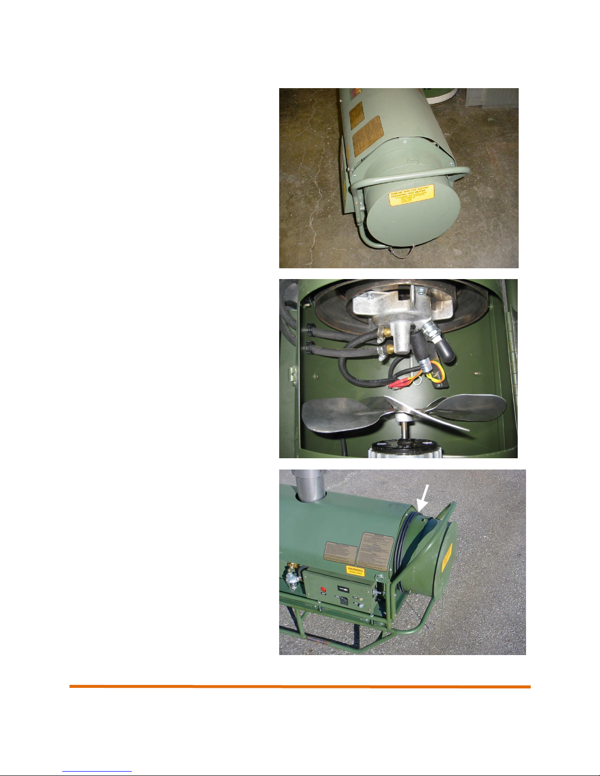
1.2 Description of Major Components
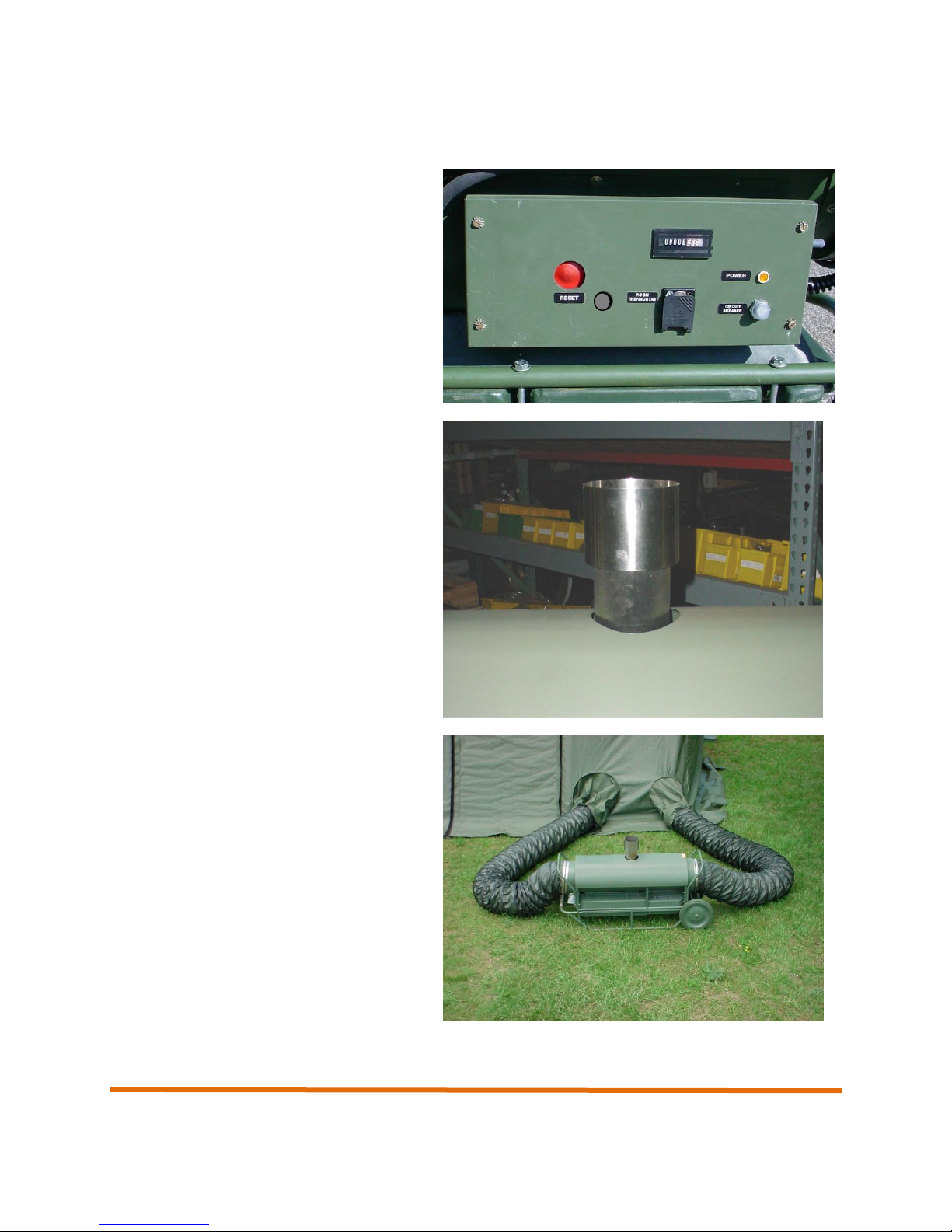
Control Panel – Contains all operation
controls for heater including power input
connector, optional remote room thermostat
connector, and hour meter.
Exhaust Stack Extension– The exhaust
stack extension is installed in the exhaust
outlet on the top of the heater and acts to
direct the combustion gases away from the
heater.
An internal screen in the exhaust stack
extension acts as a spark arrester.
Inlet and outlet ducts – 15 foot flexible
ducts connect to the shelter duct tunnels and
circulate heated and unheated air through the
shelter.
Operation and Maintenance Manual
11
Operation and Maintenance Manual
End plug – Installs into the inlet end of the
heater and is used to house accessory items
such as the remote room thermostat.
Burner assembly – The burner assembly is
where all combustion occurs within the
Camfire heater. Atomized fuel is mixed with
air and ignited by the spark plug to create the
heat circulated through the shelter.
Power cable – A 6-foot long AC power cable
that connects the heater with a 220` VAC
power source. The power cable is wrapped
around the inlet duct adapter.
12
Operation and Maintenance Manual
Remote Room Thermostat – Permits
automatic temperature control inside a
shelter. The remote room thermostat hangs
inside the shelter and monitors the shelter
temperature. If the shelter temperature falls
below the set point on the thermostat, the
heater will start and begin supplying heat
until the set point is reached.
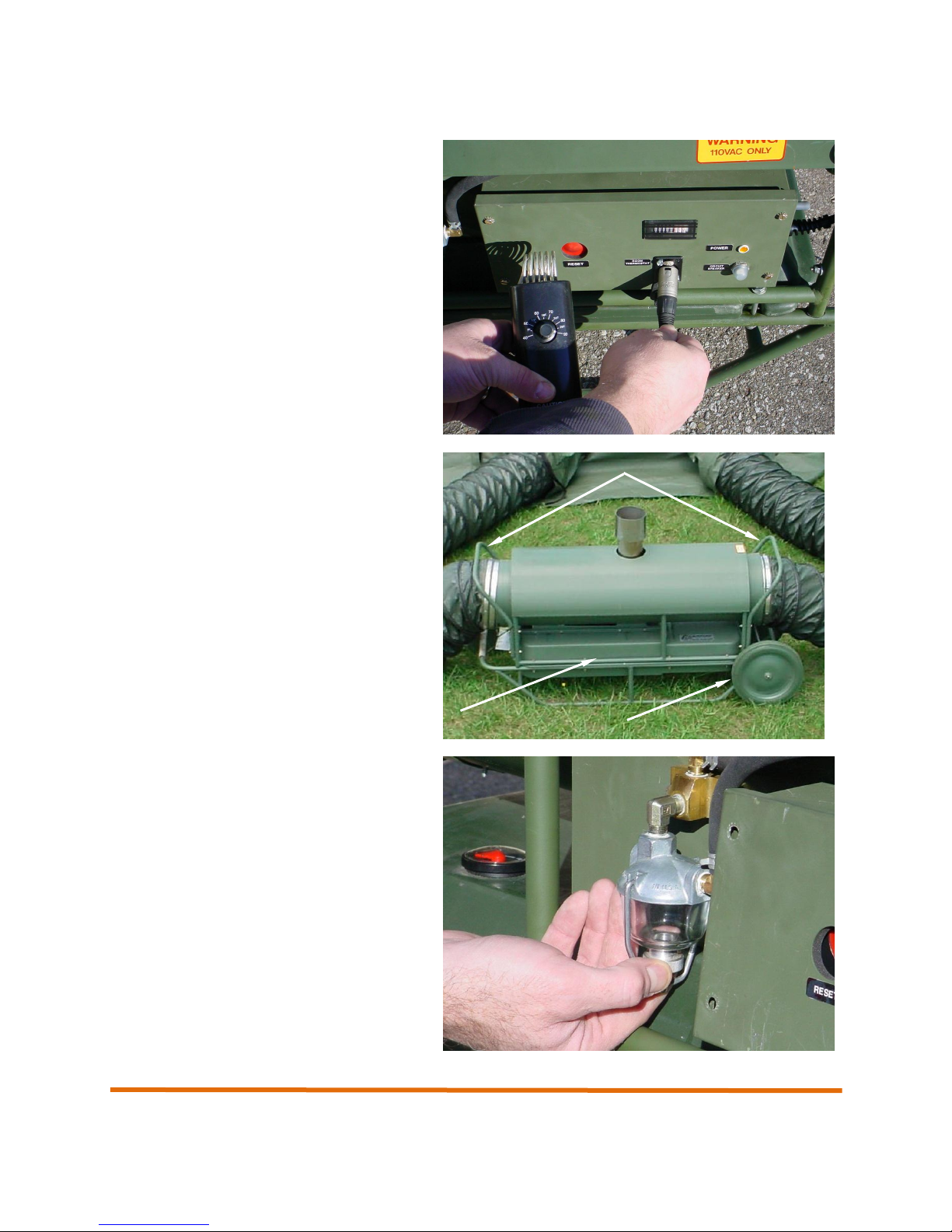
Roll bars, handles, and local transport
wheels* – Handles are located at either end
of the heater and permit the heater to easily
be moved into position. Roll bars are located
around the heater and act to protect the
heater from damage. Local transport wheels
(optional accessory) permit the heater to be
rolled into position.
* Local transport wheels are an optional accessory.
Sediment strainer assembly. Allows for
visual inspection of fuel for dirt and water. Is
able to be easily removed and cleaned.
13
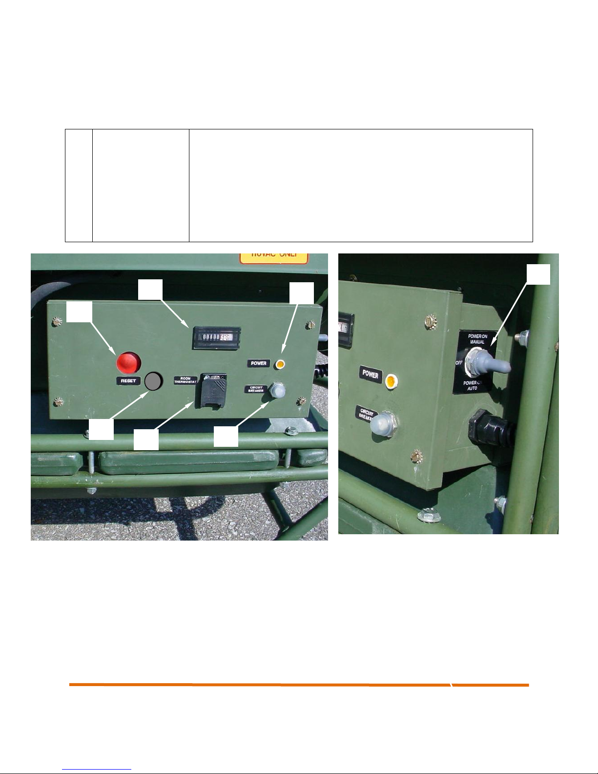
No.
Control
Description
1
Reset
Resets the heater in the event a problem shuts the heater down or a fault
condition occurs
2
Power ON AUTO/
ON MANUAL
Turns heater power on and selects AUTO or MANUAL heat mode
3
Pilot Light
Indicates that power is supplied to the heater.
4
Thermostat Jack
Permits the connection of the remote thermostat assembly.
5
Hour meter
Displays the total number of operating hours for the heater.
6
Circuit Breaker
Protects the heater against circuit overload
7
View Port
Allows the user to view the diagnostic LEDs, for troubleshooting and repair
1
2
3
4
5
6
7
1.3 Controls and Indicators
Operation and Maintenance Manual
Figure 1-1. CAMFIRE Control Panel
14
Operation and Maintenance Manual
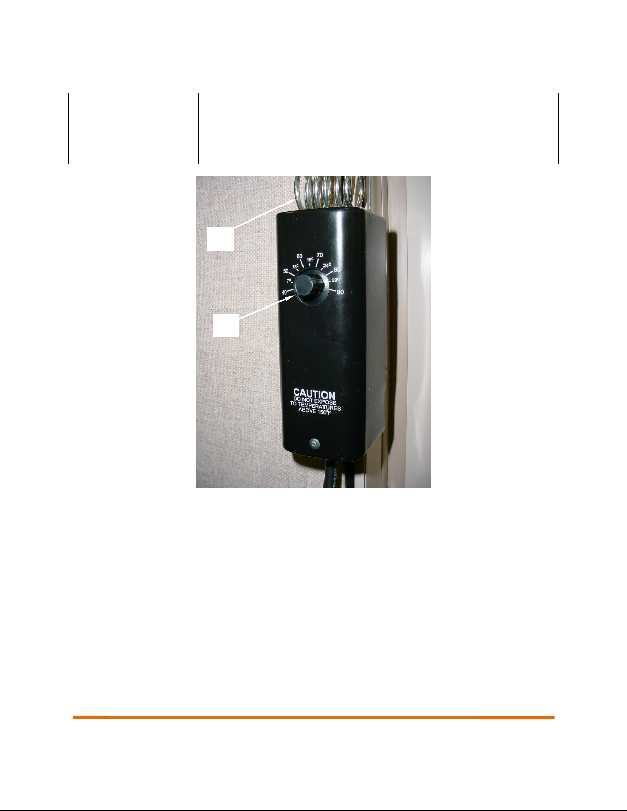
No.
Control
Description
1
Variable
Temperature
Control
Placed inside the shelter being heated, permits the operator to set the
desired temperature of the shelter.
2
Temperature
Sensing Coil
Located on the top of the remote room thermostat, monitors the temperature
of the shelter.
1
2
Figure 1-2. Remote Room Thermostat
15
Operation and Maintenance Manual
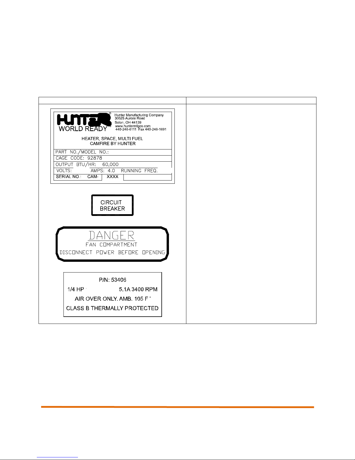
WARNING Label or Data Plate
Location/Description
Located on the side of the heater, the data plate
provides pertinent data including Model Number
and Serial Number
Located on the control panel, identifies the
circuit breaker. See section on controls and
indicators.
Located near the fan compartment, warns user
of electrical shock potential inside fan
compartment.
Located on fan assembly, label identifies part
number and performance specs of fan.
1.4 WARNING Labels and Data Plates
The following section contains a description of all WARNING labels and data plates associated with the
Camfire Heater.
Table 1-1. CAMFIRE Heater Warning Labels and Data Plates
16
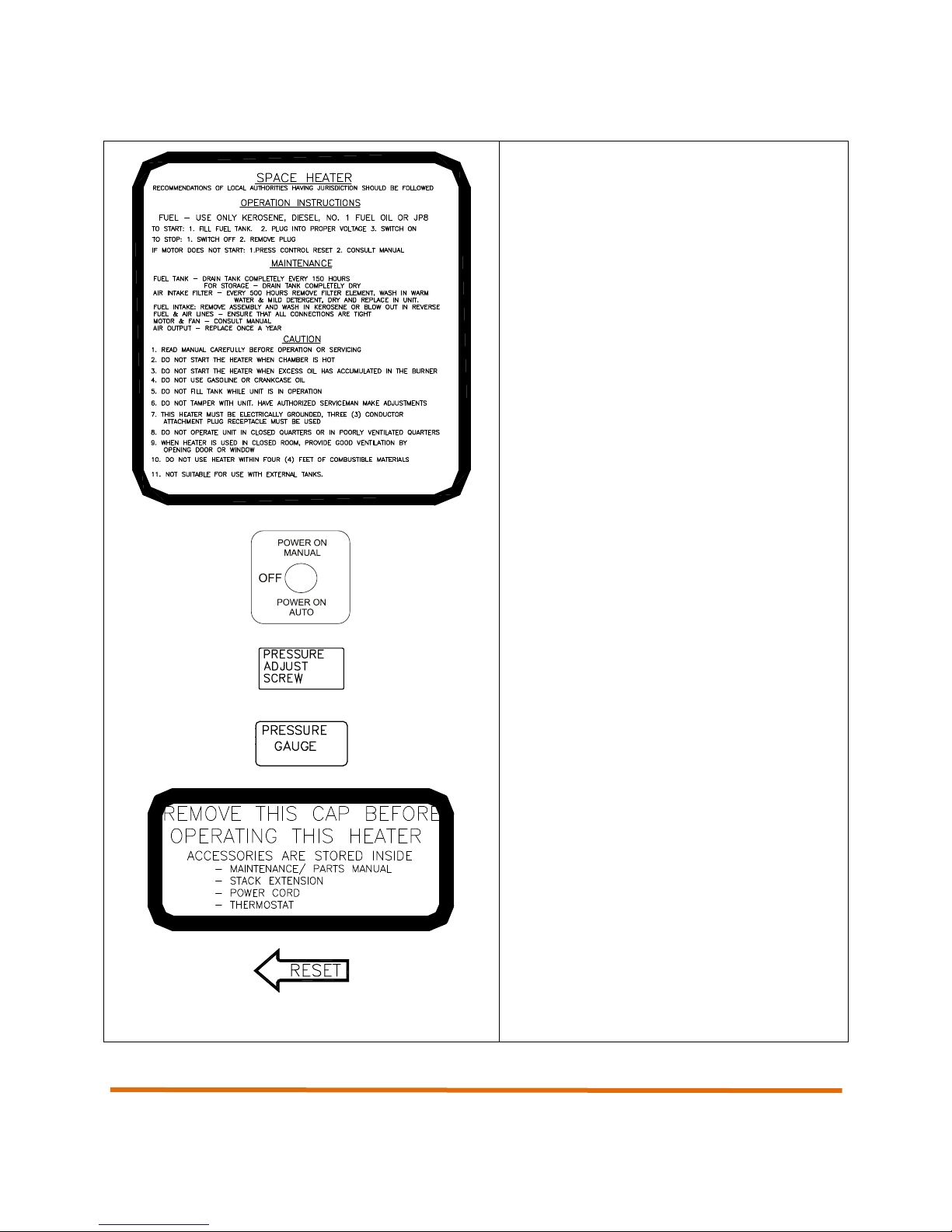
Operation and Maintenance Manual
Located on side of heater, label lists the
operating procedures for the heater in
abbreviated form.
Located on the control panel, identifies power
switch.
Located inside heater near air pump, identifies
pressure adjustment screw.
Located inside heater near burner assembly,
identifies pressure gauge.
Located on end plug at end of heater, identifies
the fact that the cap must be removed before
operation. Also informs user of accessories
stored inside end plug.
Located on control panel, identifies Reset
switch.
17
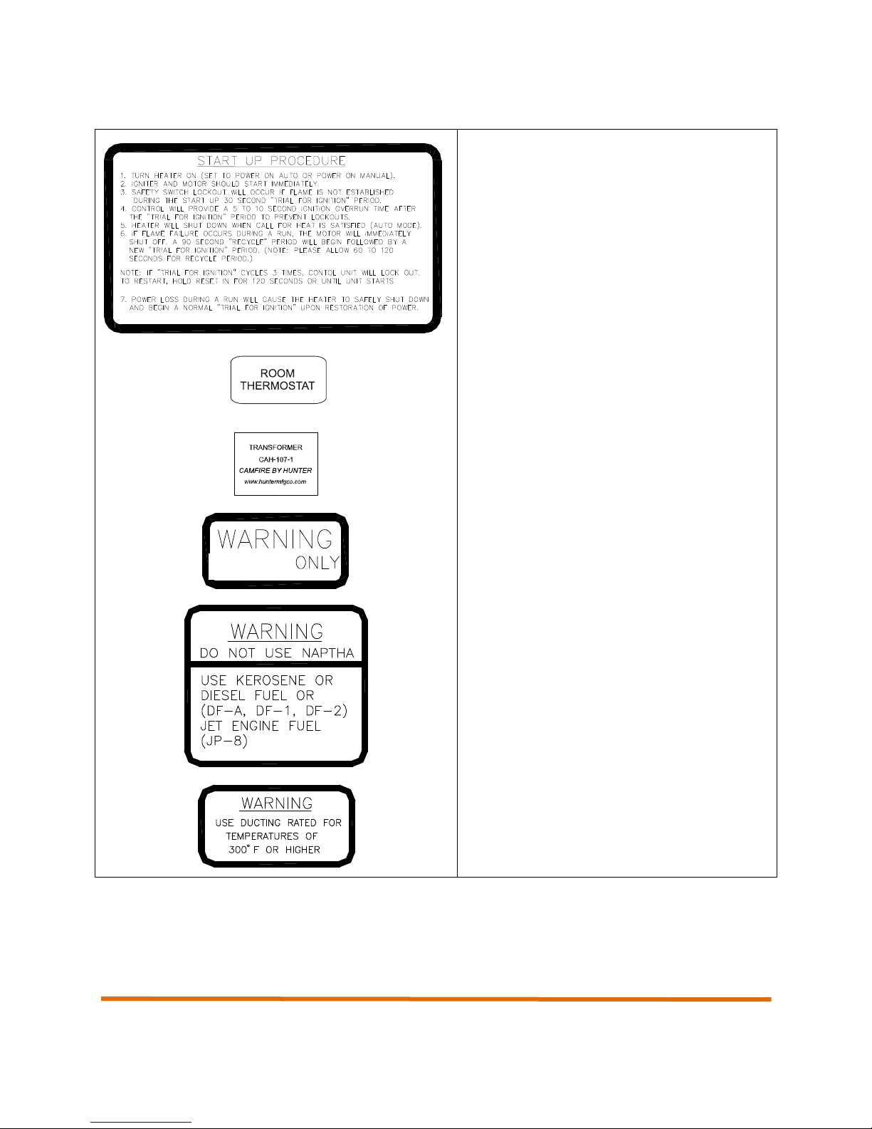
Operation and Maintenance Manual
Located on side of heater, details heater startup procedures.
Located on control panel, identifies remote
ROOM THERMOSTAT.
Parts ID tag located on the ignition transformer.
Located on control panel, alerts user that only
220VAC power should be used.
Located near fuel filler cap on side of heater,
warns user against the use of naptha and
identifies all approved fuels.
Located near duct connections at end of heater.
Warns user that only approved flexible ducts
rated for temperatures of 300 degrees F or
higher can be used.
220 VAC
18

MV60S-EU, MV60T-EU,
Input Heat Rating
BTU/Hour
90,000
Output Ratings
Clean-air Output, BTU/Hour
60,000
Volume, CFM (Approximate)
600
Other Ratings
Current, starting
3.5 AMPS
Current, running
2.2 AMPS
Voltage
220 VAC
Frequency
50/60 Cycles
Fan/Pump Motor
1/4 HP
Air Pump Pressure
5.0 PSI
Fuel Nozzle
Meter Size
0.65 GPH
Spray Angle
80 DEGREES
Fuel
Kerosene, DF1, DF2,
Fuel Oil, JP8 Only
Tank Capacity
8.5 GAL
Flexible Ducts (2)
12 inch diameter
15 ft Length
Dimensions (Without Stack
Extension)
W15” L46” H25”
Weight (Without Fuel)
105 LBS
1.5 CAMFIRE Heater Specifications
Table 1-2. Camfire Heater Specifications
Operation and Maintenance Manual
19

Operation and Maintenance Manual
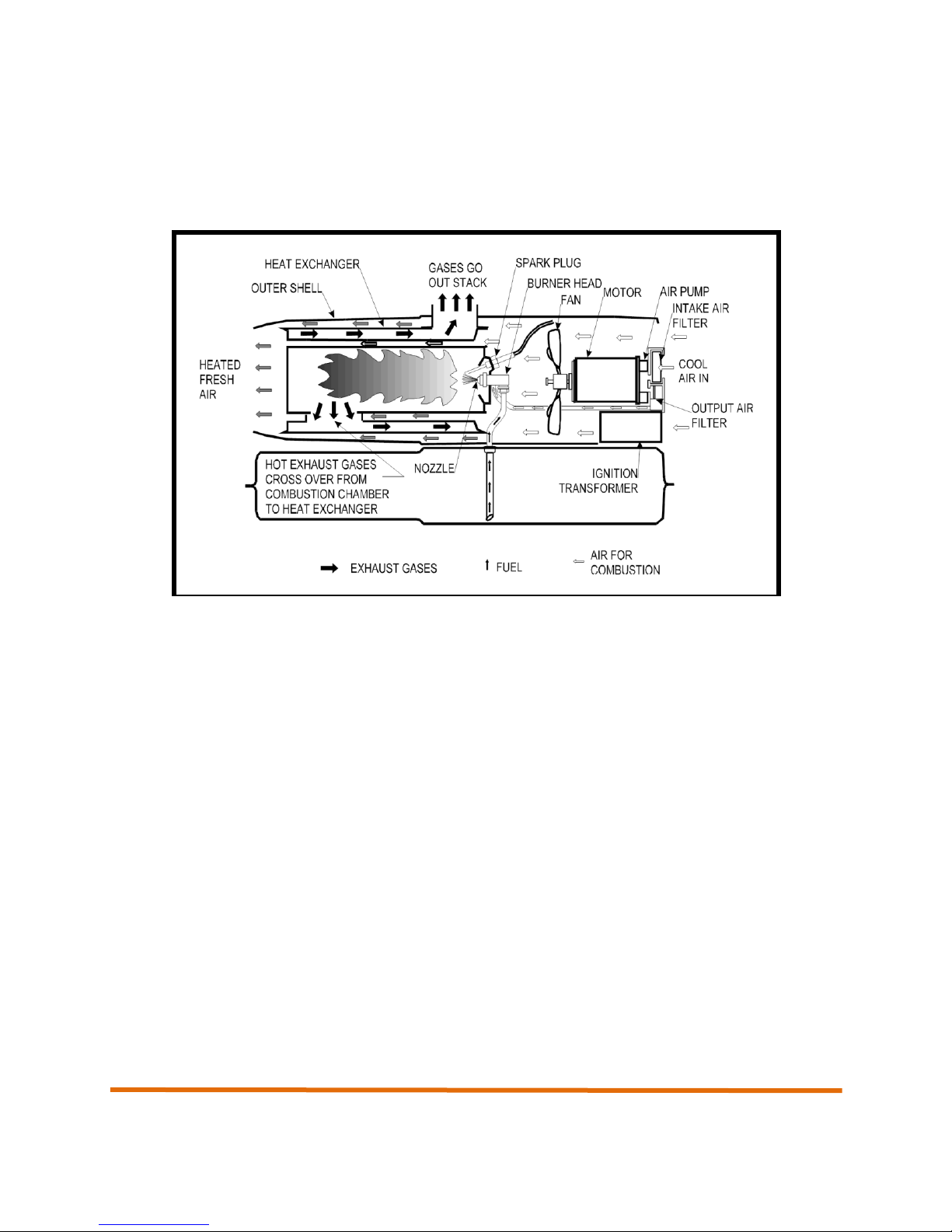
1.6 Principles of Operation
Fuel System
An air pump on one end of the motor shaft forces the air through the nozzle. The moving air lifts fuel from
the tank or from the remote fuel source ( AND version) by a siphon action and carries it into the
combustion chamber in a fine spray.
Air System
The air system is divided into two parts, both are supplied with air from a fan that is attached to the other
end of the motor.
Part of the air from the fan enters the combustion chamber where it mixes with the atomized fuel to
become a combustible mixture, and also mixes with the burning gases to complete the process of
combustion.
The exhaust gases from the combustion chamber circulate within the inner surfaces of the heat
exchanger. They are then ducted out of the heater through the stack adapter on its’ top and out of the
heater space through a flue pipe.
The rest of the air from the fan passes over and around the combustion chamber and through the heat
exchanger where it is heated and emerges from the front of the heater as a powerful stream of heated
fresh air, without being mixed with the products of combustion.
Ignition System
The ignition system consists of a transformer and spark plug. The transformer increases the input voltage
to a very high potential that causes an arc to be drawn between the electrodes of the spark plug. The arc
is used to ignite the fuel and air mixture within the combustion chamber.
Control System
The safety control circuit consists of a duct over heat switch, a light sensitive photocell, and a safety
control. The safety control will trip if the heater fails to ignite or the flame goes out, thereby causing the
heater to shut down. The safety control has two diagnostic LEDs which can be seen through a hole in the
front of the control panel.
The photocell is used to sense the presence of light due to the flame inside the combustion chamber. It
varies its’ electrical resistance in relation to light rays. When under the influence of light, the cell has very
low resistance. The resistance is high when little or no light strikes the light sensitive surface. The flame
sensor’s function is to control the safety control.
A ”duct over-heat” switch is located at the outlet end of the heater. This switch will shut down the heater if
the duct temperature exceeds approximately 275 deg. F.
A thermostat accessory, Part No. CAH-134-1, may be incorporated into the electrical circuit of the heater.
The thermostat can be set to any desired temperature between 35 deg. F and 95 degrees F. When the
20
Operation and Maintenance Manual
temperature of the surrounding air reaches the pre-set temperature, the thermostat contacts open and
cause the heater to shut down. When the air cools, the thermostat contacts close and the heater recycles.
A ”duct over-heat” switch is located at the outlet end of the heater. This switch will shut down the heater if
the duct temperature exceeds approximately 275 degrees F.
Figure 1-3. System Operational Diagram (simplified for clarity)
21

Operation and Maintenance Manual
22

Operation and Maintenance Manual
Chapter 2
Setup and Operation of the
CAMFIRE Heater
23

Operation and Maintenance Manual
24
Operation and Maintenance Manual
2. Setup and Operation of the CAMFIRE Heater
2.1 Preparing the Heater for Operation
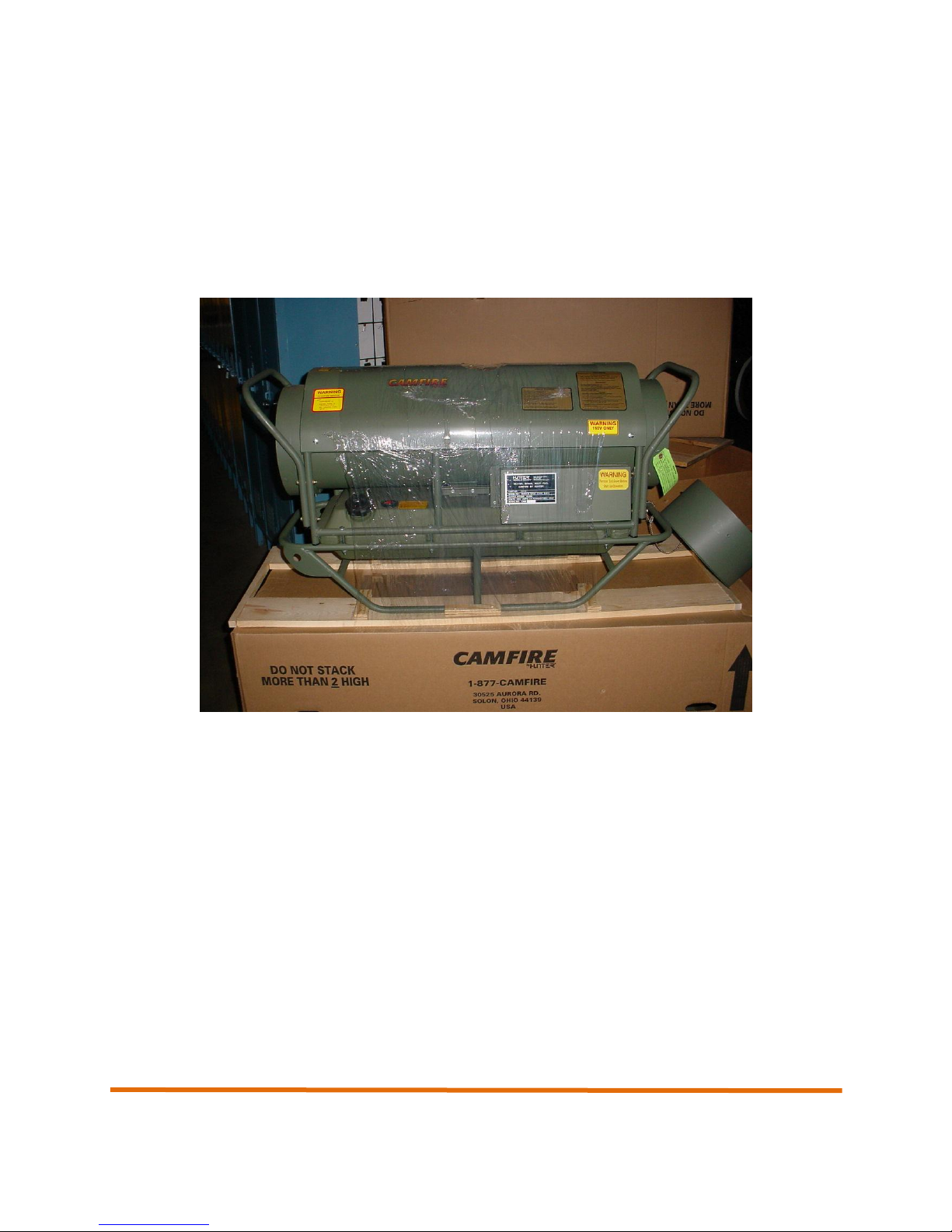
2.1.1 Unpacking
The Camfire heater is shipped mounted to a shipping pallet and wrapped in a plastic wrap material. When
unpacking the heater, remove all protective material covering the heater and remove the unit from the
shipping pallet.
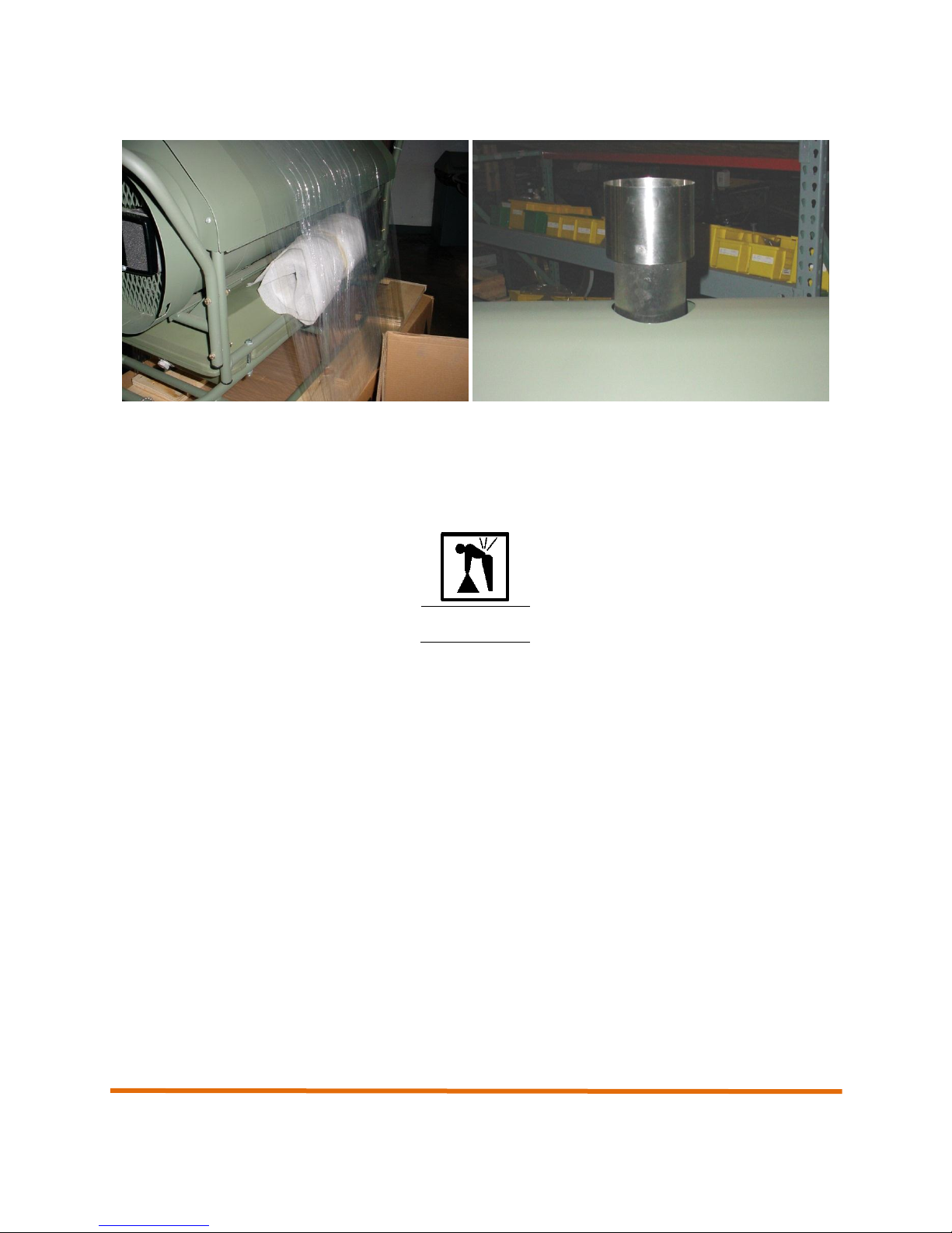
2.1.2 Installing the Exhaust Stack Extension
The exhaust stack extension is wrapped in foam and packaged to the side of the heater. Unwrap the
exhaust stack extension and install on the top of the heater by engaging the exhaust stack extension into
the exhaust port at the top of the heater. Push down and seat securely.
25
Operation and Maintenance Manual
WARNING
2.1.3 Removing the Accessories
Remove the end plug by pushing in and rotating counterclockwise to release from the J-slot. Pull the end
plug to disengage it from the heater and remove the remote room thermostat. Set the thermostat aside.
2.2 Siting Considerations
The CAMFIRE heater weighs approximately 105 pounds dry weight (48 kg). A fully fueled
heater weighs 165 pounds (74.8 kg). Two persons must carry the CAMFIRE heater when
lifting or lowering the unit. Be sure to lift with legs, not back, to prevent injury.
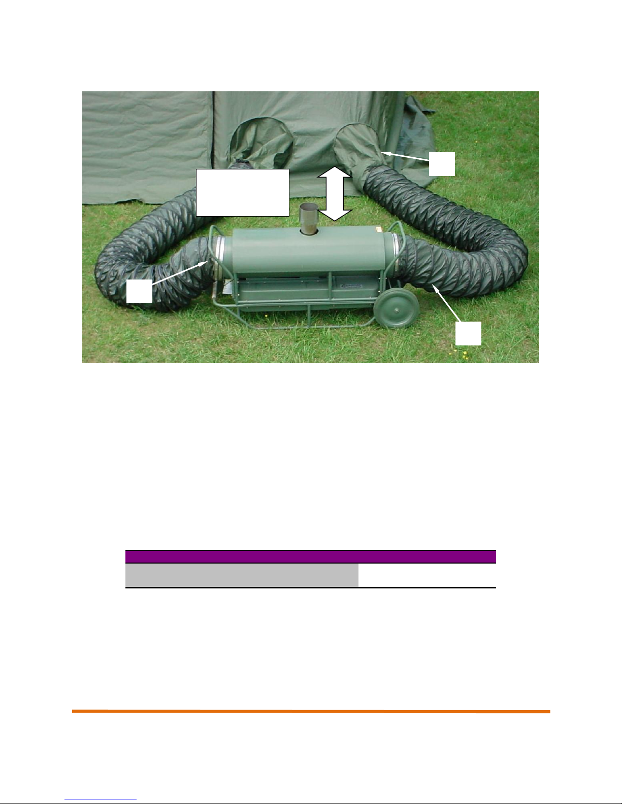
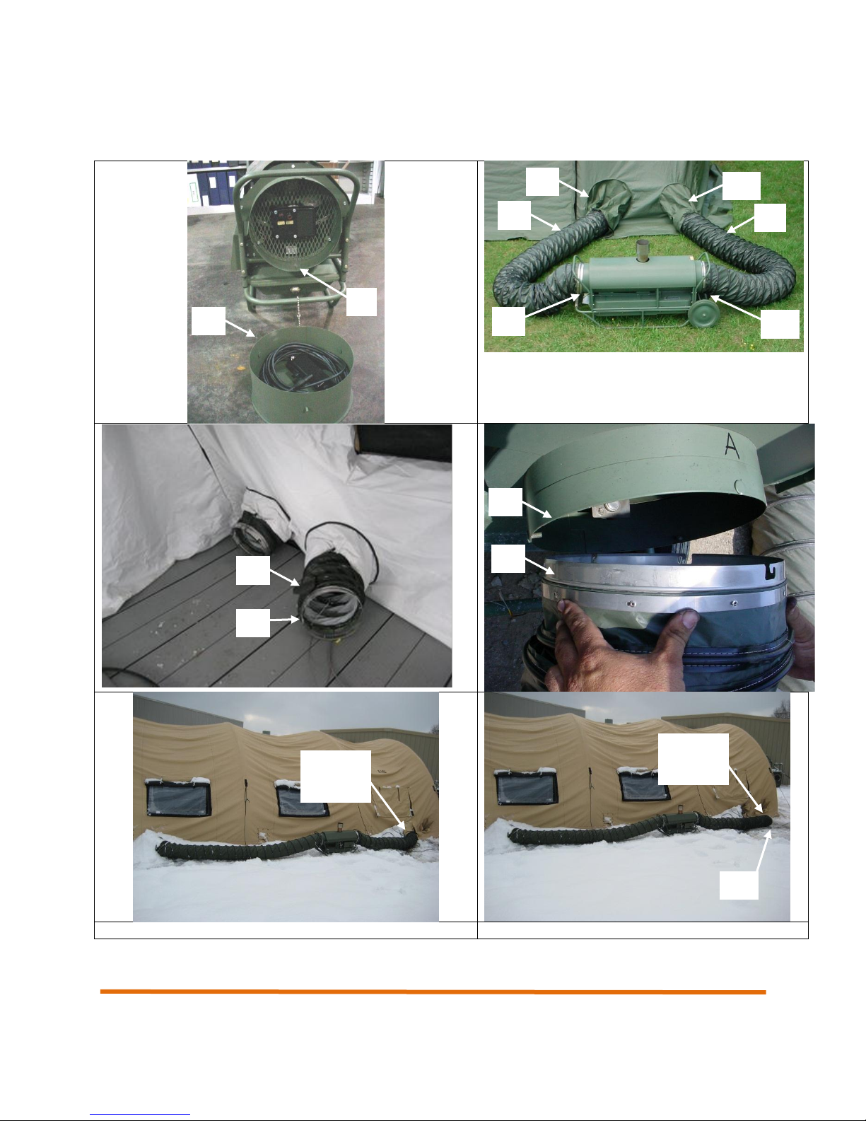
The CAMFIRE heater site location will be dictated by the location of the shelter since the heater inlet (1)
and outlet (2) ducts must be able to reach the shelter duct tunnels (3). (see photo next page)
The heater site must be as level as possible and free of combustible material (e.g. dried twigs, leaves.
etc.). If snow is present, it should be removed from the area immediately beneath and around the heater.
The site should be selected so that the heater will be positioned at least 2 feet (61 cm) from combustibles,
including the shelter wall.
26
Below 320F
Above 320F
Use Heated Air Outlet Duct Only
X
Use Air Inlet Duct and Heated Air Outlet Duct
X
Position heater
at least 2 feet
from shelter wall
1
2
3
Operation and Maintenance Manual
Positioning the Heater Outside Shelter. Place heater on the side of the shelter that has the shelter duct
tunnels. The heater should be a minimum of 2 feet (61 cm) from shelter walls. If possible, position the
heater so that the control panel faces away from the shelter wall. Position the heater so that the two
supplied 15-foot flexible ducts can be connected to the heater and the shelter duct tunnels.
2.3 Setup
2.3.1 Attaching the Flexible Ducts
General. Two air ducts, 15 feet in length and 12 inches in diameter, connect to the inlet and outlet ends
of the heater and move air from the interior of the shelter, through the heater, and back to the interior of
the shelter. In conditions where the outside ambient temperature is above freezing, only the heated air
supply duct is used. In this way, the heater draws unheated air from the outside. Operating the heater
without input ducting in warmer temperatures allows the heater to run cooler, thus preventing safety
overheat shutdown.
Table 2-1. Flexible Duct Usage vs. Outside Temperature
27
Operation and Maintenance Manual
WARNING
Installing the Air Supply and Return Ducts (re-circulation mode). To install the heated air return and
air supply ducts (NOTE: air return duct to be installed only if outside temperatures are below freezing),
remove end plug (1) from the heater duct adapter (2) on the air inlet end of the heater by pushing in and
rotating clockwise to disengage the protruding pins on the end plug from the J-slots in the heater duct
adapter. Remove the power cable stowed inside the end plug and set aside.
During heater operation, air leaving the heated air outlet of the heater and passing
through the heated air return duct may exceed 220°F (104°C). Make sure shelter
personnel are aware of burn hazards and equipment hazards presented by the heated air
exiting the heated air duct.
CAUTION
Wear gloves whiles handling ducts. There may be sharp metal edges or burrs that could
cut you.
NOTE: The heater ducts are outfitted with J-slot, twist lock bands on each end. They can only be
attached one way. Make sure to match up the ends before attaching to the shelter. Locate the heated air
supply duct (3). Make sure inside and outside of duct are free of damage, dirt, and obstructions prior to
attachment to the heater assembly. Insert the outlet end (4) of the duct into the shelter duct tunnel (5)
closest to the heated air outlet end (6) of the heater as indicated by the label “Heated Air Outlet” on the
upper housing assembly. Make sure about 12 inches of the outlet end (4) protrude into the shelter (7) so
that the air can be directed away from the inlet properly. Secure the shelter duct tunnel tie straps. Do not
secure the straps so tightly that the air flow within the duct is restricted. Attach the end of the duct with the
J-slot bracket (8) to the duct adapter (9) on the heated air outlet end (6) of the heater. Engage the J-slot
onto the protruding pins on the inside of the duct adapter and push in fully. While pushing the duct in,
rotate the duct counterclockwise until it locks in place.
IMPORTANT
If using the heater on a shelter with a plenum, move the plenum to the side so it does not
obstruct the airflow. DO NOT ATTACH THE HEATER TO THE SHELTER PLENUM. The
heater will do a much better job of heating by blowing the heat on the floor.
Insert the end of the duct without the J-slot mounting bracket into the shelter duct tunnel (14) closest to
the air inlet end (15) of the heater as indicated by the label “Air Inlet” on the upper housing assembly.
Secure the shelter duct tunnel tie straps (16). Do not secure the straps so tightly that the air flow within
the duct is restricted. Attach the end of the duct with the pins onto the J-slots (17) to the duct adapter (18)
on the air inlet end of the heater. Engage the protruding pins onto the J-slots on the duct adapter and
push in fully. While pushing the duct in, rotate the duct counterclockwise until it locks in place.
28
Operation and Maintenance Manual
Re-circulation mode
Outside air mode (see next section)
7
1 2 5
3
4
6
8
9
14 3 15
12
Duct
shelter
Duct
shelter
inside
outside
29
Operation and Maintenance Manual
WARNING
2
3
Installing the Air Supply and Return Ducts (outside air mode) If outside temperatures are above
freezing, the inlet of the air supply duct (12) should be located outside the shelter, drawing outside air, in
accordance with Table 2-1. This helps to keep the heater from shutting down on overheat unexpectedly.
Make sure the duct is still attached to the heater as this keeps rain and snow from being drawn into the
fan compartment. Also, make sure inside and outside of duct and the grill are free of damage, dirt, and
obstructions prior to attachment to the heater assembly.
Never use gasoline in this heater. Never use JP-4. The heater is designed to run only on
DF-1, DF-2, DF.A, JP-5, and JP.8. Failure to use only authorized fuels may result in fire
or explosion.
2.4 Before Operation Preventative Maintenance Checks and Services (PMCS)
Perform the “Before Operation PMCS” on all CAMFIRE heater components as outlined in section 4.2,
prior to preparing the heater for use. All scheduled maintenance must be performed on the heater and its
associated equipment prior to use.
2.5 Fueling
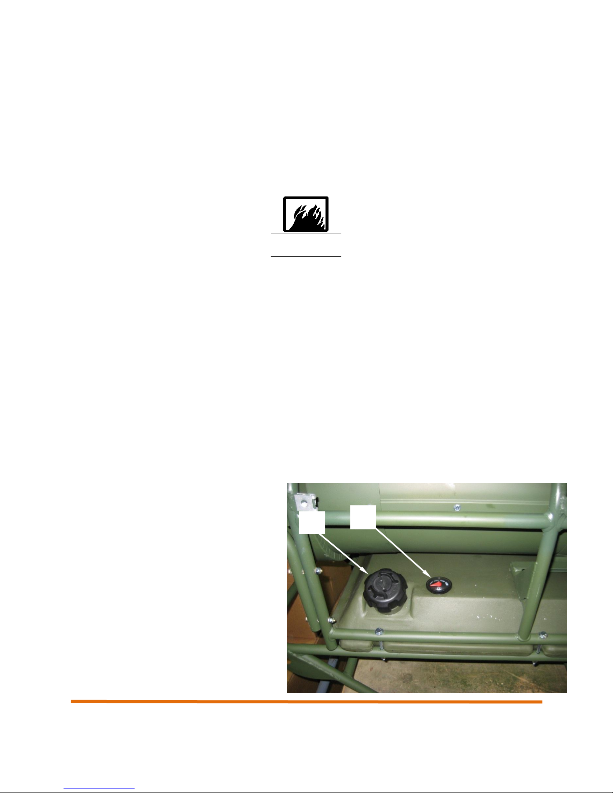
2.5.1 Fueling the Internal Tank (MV60S-EU, MV60T-EU)
Remove the internal fuel tank cap (2) and fill the internal tank with an approved fuel as detailed in section
1.5 of this manual.
Install the internal fuel tank cap (2) and hand tighten securely.
Open the vent on the top of the fuel tank cap
(2).
CAUTION: For fuel tanks with a manual vent.
The fuel tank vent should always be open to
prevent pressure from building up in the fuel
tank. Only close the vent when the heat is
tilted, such as when moving the heater on its
optional wheels.
The fuel level in the tank is displayed on the
fuel gauge to the right of the fuel tank cap (3).
30

Operation and Maintenance Manual
1
2
3
4
5
2.5.2 Connecting and operating the Remote Room Thermostat
The optional remote room thermostat (1) allows the operator to control the environment inside the shelter
automatically by monitoring the temperature and subsequently controlling the heat output of the Camfire
heater. (see photo next page)
To connect the remote room thermostat (1), engage the plug (2) on the end of the cable into the
connector (3) on the control panel of the heater labeled “ROOM THERMOSTAT”. Push the plug in
securely until it clicks in position. Rotate the dial on the room thermostat fully counter clockwise so that it
does not turn on unexpectedly while setting up.
Route the thermostat control into the shelter and hang from a convenient location. Be sure to position the
control so that it is not in the direct path of the heated air outlet or the cold air at the entrance to the
shelter. You may need to try several locations in the shelter before a suitable location is found.
To use the room thermostat move the control panel switch (4) to the ON AUTO position. Adjust the dial
until the heater comes on. If the room temperature is not satisfactory, adjust the room thermostat as
necessary. NOTE: The numbers (5) on the room thermostat are for reference only. You should remember
that if the shelter temperature is too cold (or hot) simply adjust the room thermostat.
31

Operation and Maintenance Manual
LENGTH OF CORD
WIRE SIZE (AWG)
100 ft
NO. 14
200 ft
NO. 12
300 ft
NO. 10
400 ft
NO. 8
450 ft
NO. 6
2
1
2.5.3 Connecting the Power Cable
Ensure that the main power switch (1) on the Camfire heater control panel is in the OFF position.
Uncoil the power cable (2) and connect the male end of the power cable to a 220 VAC, 50/60 cycle single
phase power source with GFCI.
If an extension cord is required, ensure that it is a three wire cord and of adequate size, as listed in the
following table.
Table 2-2. Extension Cord Size Requirements
32

Operation and Maintenance Manual
WARNING
2.6 Final Checks Before Operation
1. Make sure that all the connections are secure, power, room thermostat, ducts, etc.
2. Open internal fuel tank cap and check for an adequate fuel supply. Make sure the fuel tank cap vent
is open.
3. Ensure that the power switch on the control panel is in the OFF position.
4. Plug the Camfire heater power cord into a grounded, 220 VAC power supply outlet.
5. The heater assembly is now ready for operation.
2.7 Starting and Operating the Heater
2.7.1 Starting the Heater
1. Set the toggle switch to the ON MANUAL position if the heater is not being operated with the room
thermostat control. If the room thermostat accessory is being used, set the toggle switch to the ON
AUTO position and set the dial on the room thermostat to the desired temperature. This will initiate a
“call for heat”. The heater will start immediately provided that the surrounding air is cooler than the
setting of the dial. The heater will continue to operate until the temperature of the surrounding air
reaches the dial setting. It will then shut down and cycle on when the temperature drops.
2. Safety control lockout will occur if flame is not established during the startup 15 second “trial for
ignition” period. To restart, the safety switch must be manually reset. See section 3 for details.
3. Control will provide a 5 to 10 second ignition overrun time after the “trial ignition period” to prevent
lockouts.
4. Burner will turn off when call for heat is satisfied. CAUTION: There is no post purge on this heater so
surfaces will remain hot for some time after shut down.
5. If flame failure occurs during a run, the motor will immediately shut off. A 90 second “recycle” period
will begin followed by a new “trial for ignition” period. (Please allow 60 to 120 seconds for recycle
period). Flame failure may occur due to a heater failure or, if the heater runs out of fuel.
NOTE
If trial for ignition locks out three times, control will “latch-up”. To reset, refer to section 3.
Only a qualified technician should attempt to rest the control after latch-up. The
problem that caused the malfunction must be corrected before returning the
burner to normal operation. Failure to do so may lead to fire and or damage to
equipment or personnel. (see troubleshooting)
33

Operation and Maintenance Manual
6. Power loss during a run will cause the burner to safely shut down and begin a normal trial for ignition
upon power restoration.
2.8 Refueling During Operation
The heater must not be refueled while it is operating. To refuel the heater, turn the power switch to the
OFF position. Refuel in accordance with the section entitled “Fueling the Internal Fuel Tank”.
2.9 Shutting Down the Heater
1. Move the heater switch to the OFF position.
2. If the heater is equipped with a thermostat accessory, turn the dial to the”No Heat” position.
2.10 Preparing for Movement or Storage
2.10.1 Preparing for Movement
1. To prepare the Camfire heater for movement, ensure that the heater has been shutdown in
accordance with section 2.9 and that it is completely cool.
2. Unplug the power cord from the power source as well as the Camfire control panel. Coil the power
cord around the inlet adapter.
3. Remove the remote room thermostat from the shelter (if used) and disconnect from the thermostat
connector on the control panel. Coil the remote room thermostat cable and stow it in the end plug
along with the power cable.
4. Remove the heated air outlet duct from the shelter duct tunnel. Stow the duct in a location that will
protect it from weather extremes, cuts, tears, or other damage.
5. Remove the air inlet duct (if used) from the remaining shelter duct tunnel. Stow the duct in a location
that will protect it from weather extremes, cuts, tears, or other damage.
6. Ensure that the remote room thermostat is neatly coiled inside the end plug as previously discussed.
Install the end plug in the end of the heater by aligning the pins on the end plug with the J-slots on the
heater duct housing. Push the end plug in place and rotate clockwise to lock in place. Release the
end plug.
7. Remove the stack extension and stow in a protected location along with the ducts.
34

Operation and Maintenance Manual
2.10.2 Preparing the Heater for Storage
To prepare the heater for storage, follow all procedures detailed in the previous section to prepare the
heater for movement.
In addition, drain the fuel tank and purge with an approved agent. Start the heater and run out all residual
fuel left in the system. Make sure the fuel tank vent is open. Empty the sediment strainer.
CAUTION: The fuel tank vent should always be open to prevent pressure from building up in the fuel
tank. Only close the vent when the heat is tilted, such as when moving the heater on its optional wheels.
Lubricate all hinges.
Fog the entire heater with a thin layer of WD-40 or equivalent light oil spray to protect all metal surfaces.
Store the heater in a location protected from moisture and sand.
35

Operation and Maintenance Manual
36

Chapter 3
Operation and Maintenance Manual
Troubleshooting
37

Operation and Maintenance Manual
Step
LED
Status
Description
A R
1 O O
Power ON/Standby, Control waits for Room Thermostat circuit to close or Manual
ON
2 I O
Call for heat, Room Thermostat circuit closed. The amber LED turns ON. For the
first 3 of 4 seconds, the control performs a self-test. If the photocell senses flame, the
control repeats this test until flame is no longer detected. During this time the amber
LED blinks off momentarily every 3 or 4 seconds
3 O O
Burner ON. After the self-test, the amber LED turns OFF. The igniter starts, followed
1 second later by the motor.
4 O O
TFI (trial for ignition), the photocell must detect flame within 15 seconds. After flame
is detected, the igniter stays on another 10 seconds for flame stabilization.
5 O O
RUN, the burner continues firing as long as the photocell senses flame and the
overheat does not trip.
6 O I
LOCKOUT, if the photocell does not sense flame within 15 seconds after the burner
starts, lockout occurs. The control turns the RED on constant.
To RESET, push in and hold red button for 1 second, then release.
N/A
I I LATCH-UP, If the control locks out 3 times during a single call for heat, latch-up
occurs. The control turns on both the amber and red LEDs constant.
Warning! Only a qualified technician should attempt to rest the control after
latch-up. The problem that caused the malfunction must be corrected before
returning the burner to normal operation. (see maintainer level
troubleshooting)
3. CAMFIRE Troubleshooting
3.1 Introduction
Should you encounter any problems with the operation of a heater, the chart on the following pages may
help. For each problem there is a list of ”possible causes”. The corrective action column tells you how to
correct the problem or tells you by means of a section and paragraph number where to find detailed
instructions for correcting it.
In troubleshooting, remember that the air pump is part of the fuel system because the air it supplies lifts
the fuel from the tank and pushes it through the nozzle.
NOTE
Be sure to follow all cautions and warnings. They will help you prevent damage to the
heater or injury to yourself.
3.2 Operator Level Troubleshooting
3.3 Safety Control Operation and Diagnostics
During the start-up and operation of the heater the safety control goes through several steps where it is
evaluating the controls and inputs from other safety devices such as the photocell and overheat
thermostat. On the control there are to LEDs, one amber (A) and one red (R), which are visible through a
small view port on the front of the control panel. During operations the LEDs may come on and/or blink.
The table below shows various stages of operation after the heater is switched on, and the resultant LED
status. The LED status is as follows: I=ON, O=OFF
38

Operation and Maintenance Manual
Malfunction
Troubleshooting
Procedure
Motor Does Not Start
1
Heater Will Not Ignite, But Motor Runs For A Short Time.
2
Heater Burns But Puffs Of Smoke Can Be Seen; Heater Will Not Burn Steady;
Heater Burns With Odor; Heater Smokes Continuously
3
Flames and/or Black Smoke Come Out Of Stack
4
Heater Cycles Intermittently
5
Heater starts but will not stay running, RED light is flashing on control
5
Heater Ignites But Safety Control Trips, Red LED is on constant.
6 Heater will not start, amber light is flashing on the control
7
3.3.1 Operator Level Malfunction Symptom Index
The malfunction symptom index lists common malfunctions that may occur during the operation of the
CAMFIRE Heater. Find the malfunction to be eliminated and go to the indicated troubleshooting
procedure in the next section. This index cannot list all malfunctions that may occur, all tests or
inspections needed to find the fault, or all actions required to correct the fault. If the existing malfunction is
not listed, or cannot be corrected through this troubleshooting index, notify maintenance.
For purposes of this troubleshooting section, the term operator refers to someone who has been trained
in the deployment and use of the heater but has not been trained or certified in the maintenance of the
heater beyond operator level maintenance tasks.
Table 3-1. Operator Level Malfunction Symptom Index
3.3.2 Examining the Heater
WARNING!
REMOVE ALL POWER BEFORE SERVICING THE HEATER. SEVERE INJURY COULD OCCUR
1. Check the fuel tank for sludge and water. If you find it, expect to find a dirty nozzle and/or sediment
strainer.
2. Spin the fan to be sure it turns freely. If it is stiff, look for a worn or dry bearing on the fan end of the
motor, or for binding pump rotor.
3. Check the heater for dirt and foreign materials around the pump, fan and air filters. Be sure the heater
is reasonably clean before test-firing.
4. Check the heater cord for obvious breaks or other unsafe conditions. If the cord is doubtful repair it or
replace with a new one before test firing.
39

Operation and Maintenance Manual
No.
Malfunction
Possible Cause
Corrective Action To Take
1.
Motor does not start.
A. Safety control locked out.
(see section 3.3)
1. Push and hold red reset button
for 5 seconds.
B. No power or low voltage at
heater.
1. Check that heater is plugged
in.
2. Ensure voltage at heater is the
same as indicated on heater Data
Plate located on electrical panel
cover and as indicated in the
Specifications, Section 1.5.
3. Use an extension cord of
sufficient gauge to carry the
electrical load of the heater (see
Table 2-3).
C. Thermostat (if used)
improperly set or defective.
1. Adjust thermostat to a higher
setting. If heater still does not
start, continue with Step 2.
2. Place the toggle switch on the
heater control box to the “ON
MAUNAL” position. If heater
functions properly, replace
thermostat.
D. Fan obstructed by
mechanical damage or dirt.
1. Check for bent outer shell,
damaged fan, or damaged motor
mount.
E. Defective photocell.
1. Refer the unit to maintenance
for further troubleshooting.
F. Defective safety control.
1. Refer the unit to maintenance
3.3.3 Test Firing the Heater
1. Clean the fuel tank and fill it with at least 2 gal of fuel. A minimum of 1 gal of fuel must be in the tank
in order to operate the heater.
2. Clean the air intake filter. See Section 4.4.8.
3.3.4 Operator Level Troubleshooting Procedures
Table 3-2. Operator Level Troubleshooting Procedure
40

Operation and Maintenance Manual
No.
Malfunction
Possible Cause
Corrective Action To Take
for further troubleshooting.
G. Broken rotor or carbon
blades. Pump rotor binding.
1. Refer the unit to maintenance
for further troubleshooting.
2.
Heater will not ignite, but
motor runs for a short time.
A. Fuel tank empty, wrong fuel,
water in fuel.
1. Check level of fuel in tank. A
minimum of 1 gallon is required
for proper operation.
2. Ensure fuel is of a type
indicated on the heater or listed in
the Specifications, Section 1.5.
3. Check for water in the fuel
tank. Water in the fuel will form
visible globules in the bottom of
the fuel tank.
4. If water is found, refer the unit
to maintenance.
B. Air leak at sediment strainer.
1. Check sediment strainer and
gasket for air leaks and tightness
of thumb screw that holds the
glass bowl on.
C. Defective or damaged spark
plug.
1. Refer the unit to maintenance
for further troubleshooting.
D. Defective transformer.
1. Refer the unit to maintenance
for further troubleshooting.
3.
Heater burns but puffs of
smoke can be seen; heater
will not burn steady; heater
burns with odor; heater
smokes continuously.
A. Heater running out of fuel,
wrong fuel, water in fuel.
1. Check level of fuel in tank. A
minimum of 1 gallon is required
for proper operation.
2. Ensure fuel is of a type
indicated on the heater or listed in
the Specifications, Section 1.5.
3. Check for water in the fuel
tank. Water in the fuel will form
visible globules in the bottom of
the fuel tank.
4. If water is found, refer the unit
to maintenance for repair.
B. Dirty air filters causing
reduced air pressure through
1. Ensure air intake is not
blocked.
41

Operation and Maintenance Manual
No.
Malfunction
Possible Cause
Corrective Action To Take
nozzle resulting in low fuel flow.
2. Remove and clean air filters
(see Section 4.4.8).
C. Dirty sediment strainer.
1. Remove sediment bowl and
clean.
2. Refer the unit to maintenance
for further troubleshooting.
D. Sediment strainer loose.
1. Check sediment strainer and
gasket for air leaks and tightness
of thumb screw that holds the
glass bowl on.
E. Dirty fuel nozzle.
1. Refer the unit to maintenance
for further troubleshooting.
F. Low pump output pressure
(low motor speed, worn pump,
pump out of adjustment.
CAUTION
Never use a drill, wire or other
tool to open nozzle passage
1. Ensure that no mechanical
damage to the fan blades could
be causing low motor speed.
2. If mechanical damage is
observed, refer the unit to
maintenance for further
troubleshooting.
G. Loose output airline
between pump and burner
head.
1. Tug airline at both connections
to ensure that they are tight.
H. Inlet duct is blocked
1. Check inlet duct and make sure
it is clear. Make sure test fabric or
other FOD are not blocking the
airflow.
I. Inlet screen blocked
1. Remove inlet duct and check
debris screen for FOD. Clean as
necessary.
4.
Flames and/or black
smoke come out of stack.
A. Dirty fan or air passageway
through heater blocked.
1. Ensure that debris grill is clear.
Ensure that fan is operating
properly in accordance with
Section 4.4.5.
2. Ensure air passageway
through heater is clear.
42

Operation and Maintenance Manual
No.
Malfunction
Possible Cause
Corrective Action To Take
B. Pump output too high
causing too much fuel to be
supplied.
1. Refer the unit to maintenance
for further troubleshooting.
C. Fan loose or improperly
located on shaft.
1. Refer the unit to maintenance
for further troubleshooting.
D. Bent or damaged fan.
1. Inspect fan for damage. If
damage to fan is observed, refer
the unit to maintenance for repair.
Make sure fan is not loose on the
motor shaft.
E. Inlet duct is blocked
1. Check inlet duct and make sure
it is clear. Make sure test fabric or
other FOD are not blocking the
airflow.
F. Inlet screen blocked
1. Remove inlet duct and check
debris screen for FOD. Clean as
necessary.
G Access hatch is open
1. close access hatch
5.
Heater cycles
intermittently.
A. Room Thermostat (if used)
set too low.
1. Set thermostat to a higher
temperature for more even
operation.
B. Defective thermostat (if
used).
1. Set power switch on heater
control box to “ON MAUNUAL”
position.
2. If heater runs evenly, replace
thermostat.
C. Defective electrical supply or
defective electrical
connections.
1. Ensure extension cord is in
good condition.
2. Check mechanical and
electrical soundness of all wiring
connections in the heater (see
Schematic, Section 6).
D. Defective overheat switch.
1. Refer the unit to maintenance
for further troubleshooting.
E. Unit is overheating.
1. Check ducts for obstructions,
or kinks. Straighten ducts to
promote good airflow.
2. Remove inlet duct from shelter.
43

Operation and Maintenance Manual
No.
Malfunction
Possible Cause
Corrective Action To Take
6.
Heater ignites but safety
control trips. Heater starts
but will not stay running,
The control turns the red
LED on constant,
If photocell does not sense
flame within 15 seconds after
burner starts, lockout occurs.
A. Dirty or defective photocell.
1. Lift top cover. Open access
hatch. Remove photocell from
bracket attached to burner head.
2. Inspect glass face of photocell.
If dirty, wipe with clean soft cloth
3. Replace photocell and close
access hatch. Start heater. If
problem persists, notify
maintenance.
4. Overheat, (see 5, D and E)
B. overheat switch open
1. Let unit cool down and see if
overheat resets.
2. Check ducts and inlet screen
for blockages
D. Sediment strainer loose.
1. Check sediment strainer and
gasket for air leaks and tightness
of thumb screw that holds the
glass bowl on.
D. Sediment strainer dirty.
1. Check sediment strainer for dirt
and water. Empty bowl and clean
screen.
If problem persists notify unit
maintenance
7.
Heater will not start, Amber
light flashes on control
A. photocell seeing light
1. Make sure access cover is
closed.
2. Attach return duct
3. Disconnect photocell. If heater
starts then photocell is defective.
Notify unit maintenance.
44

Operation and Maintenance Manual
Step
LED
Status
Description
A R
1 O O
Power ON/Standby, Control waits for Room Thermostat circuit to close or Manual
ON
2 I O
Call for heat, Room Thermostat circuit closed. The amber LED turns ON. For the
first 3 of 4 seconds, the control performs a self-test. If the photocell senses flame, the
control repeats this test until flame is no longer detected. During this time the amber
LED blinks off momentarily every 3 or 4 seconds
3 O O
Burner ON. After the self-test, the amber LED turns OFF. The ignitor starts, followed
1 second later by the motor.
4 O O
TFI (trial for ignition), the photocell must detect flame within 15 seconds. After flame
is detected, the igniter stays on another 10 seconds for flame stabilization.
5 O O
RUN, the burner continues firing as long as the photocell senses flame and the
overheat does not trip.
6 O I
LOCKOUT, if the photocell does not sense flame within 15 seconds after the burner
starts, lockout occurs. The control turns the RED on constant.
To RESET, push in and hold red button for 1 second, then release.
I I
LATCH-UP, If the control locks out 3 times during a single call for heat, latch-up
occurs. The control turns on both the amber and red LEDs constant. You must use
the special procedure below to reset the control after latch-up.
Warning! Only a qualified technician should attempt to rest the control after
latch-up. The problem that caused the malfunction must be corrected before
returning the burner to normal operation.
3.4 Maintainer Level Troubleshooting
3.4.1 Test Firing
1. Check and adjust the air pressure, as described in Section 4.4.8, except that fuel must be used for
test-firing.
NOTE
It is not possible to test-fire a heater properly if this adjustment cannot be made.
2. Allow the heater to run for 15 minutes. Observe its operation during the test-run.
3. After making the pressure check, adjustment, and test firing, remove the gauge and re-install the
plug. Tighten plug until sealed. Use soapy water to check for sealing. Do not tighten.
4. If any troubles show up during the test firing, refer to the troubleshooting chart to find out how to
correct them.
3.4.2 Maintainer Level Safety Control Operation and Diagnostics
During the start-up and operation of the heater the safety control goes through several steps where it is
evaluating the controls and inputs from other safety devices such as the photocell and overheat
thermostat. On the control there are tWo LEDs, one amber (A) and one red (R) which are visible through
a small view port on the front of the control panel. During operations the LEDs may come on and/or blink.
The table below, shows various stages of operation and the resultant LED status. The LED status is as
follows: I=ON, O=OFF, B=BLINK, F=FLASHING
45

Malfunction
Troubleshooting
Procedure
Motor Does Not Start
1
Heater Will Not Ignite, But Motor Runs For A Short Time.
2
Heater Burns But Puffs Of Smoke Can Be Seen; Heater Will Not Burn Steady;
Heater Burns With Odor; Heater Smokes Continuously
3
Flames and/or Black Smoke Come Out Of Stack
4
Heater Cycles Intermittently
5
Heater starts but will not stay running, RED light is flashing on control
5
Heater Ignites But Safety Control Trips, Red LED is on constant.
6 Heater will not start, amber light is flashing on the control
7
F
O
F
O
RESET from LATCH-UP Push in and hold the reset button for about 10 seconds.
The amber and red LED’s will begin to flash alternately.
After the LED's begin flashing, continue holding the reset button for about another 20
seconds. The LED's will turn off. Release the reset button and the control will restart.
(Releasing the button before the LED's turn off will cause the control to remain in
latch-up.)
Note: The 50240 control will not reset from lockout or latch-up if power is interrupted.
O F
FLAME FAILURE If the photocell loses flame signal during operation (after the TFI),
the red LED flashes. The burner shuts off within seconds. Recycle: Control waits for
65 seconds (with red LED flashing), then begins again at Self-test. Red LED goes off
3.4.3 Maintainer Level Malfunction Symptom Index
Operation and Maintenance Manual
Table 3-3. Maintainer Level Malfunction Symptom Index
46

3.4.4 Maintainer Level Troubleshooting Procedures
No.
Malfunction
Possible Cause
Corrective Action To Take
1
Motor does not start
A. Fan obstructed by
mechanical damage or dirt.
1. Replace a damaged fan. Do
not attempt to repair.
B. Defective photocell.
(see section 4.4.10)
1. Lift top cover. Open access
hatch. Remove photocell from
bracket attached to burner head.
2. Disconnect blue and white
photocell leads.
3. Connect ohmmeter test leads
to photocell leads.
4. Hold open end of photocell
towards a light source (a 60-watt
light bulb or direct sunlight). The
resistance indicated on the
ohmmeter should be low.
5. Block off light completely by
covering the open end of the
photocell. Within 10 seconds the
resistance indicated should be
high.
6. Replace photocell if there is no
change in resistance during this
procedure.
C. Defective safety control.
(see section 4.4.9)
1. Remove 4 screws holding the
control box. Pull away from the
electrical panel but do not
disconnect any electrical
connections.
2. Attach one test lead of a
voltmeter to one of the white
leads on the distribution bar. Plug
heater in and switch on. Touch
the other test lead to first the
orange wire on the left side of the
distribution bar, then to the blue
wire on the left side of the
distribution bar.
3. If one or both wires do not read
220 volts (approximately) replace
Table 3-4. Maintainer Level Troubleshooting Procedures
Operation and Maintenance Manual
47

Operation and Maintenance Manual
No.
Malfunction
Possible Cause
Corrective Action To Take
the safety control.
NOTE
After replacing the safety control,
check the ignition transformer as
follows before starting the heater.
4. Remove screen from inlet end
of heater. Disconnect the red and
white transformer leads.
5. Attach ohmmeter test leads to
the red and white transformer
leads. The ohmmeter should
indicate an open line (no
conductance).
D. Broken rotor or carbon
blades. Pump rotor binding.
(see Section 4.4.4).
1. Remove pump end cover and
pump front cover.
2. Visually inspect rotor and
blades for breakage.
3. Ensure that the rotor and
blades are free of any lubricant or
debris.
4. Check rotor with feeler gauge
for proper clearance between
rotor and pump body (see Section
4.4.4).
E. Defective run capacitor
Check capacitor near motor in
accordance with 4.4.4
2.
Heater will not ignite, but
motor runs for a short time.
A. Fuel tank empty, wrong fuel,
water in fuel.
1. Check for water in the fuel
tank. Water in the fuel will form
visible globules in the bottom of
the fuel tank.
2. If water is found, drain and
clean tank and filter. Fill with
fresh, clean fuel.
B. Defective or damaged spark
plug.
1. Remove spark plug from
burner head. Visually inspect
spark plug for cracks or worn
electrodes.
48

Operation and Maintenance Manual
No.
Malfunction
Possible Cause
Corrective Action To Take
2. Adjust spark plug gap (see
Section 4.4.3).
3. Establish a good ground
between the spark plug and the
heater. Be careful not to let any
part of your person become a
portion of the grounded circuit.
See 4.4.3
4. Start heater; observe the spark
between the plug’s electrodes. If
the ground is good and spark
does not jump between see next
troubleshooting section.
C. Defective transformer.
WARNING
To begin the transformer test, first
ensure the heater is not plugged
in. Then, when power is required,
be EXTREMELY careful when
checking the transformer. A
transformer in good condition
produces VERY HIGH VOLTAGE
at the output terminal. See 4.2.3
1. Connect the transformer lead
to a properly gapped spark plug.
The gap should be 0.050 inch,
plus or minus 0.005 inch.
2. Establish a good ground
between the spark plug and the
heater. Be careful not to let any
part of your person become a
portion of the grounded circuit.
3. Start heater; observe the spark
between the plug’s electrodes. If
the ground is good and spark
does not jump between the
electrodes, the transformer is
defective and must be replaced.
49

Operation and Maintenance Manual
No.
Malfunction
Possible Cause
Corrective Action To Take
3.
Heater burns but puffs of
smoke can be seen; heater
will not burn steady; heater
burns with odor; heater
smokes continuously.
A. Heater running out of fuel,
wrong fuel, water in fuel.
1. Check for water in the fuel
tank. Water in the fuel will form
visible globules in the bottom of
the fuel tank.
2. If water is found, drain and
clean tank and filter. Fill with
fresh, clean fuel.
3. Check fuel tank for dirt or water
B. Dirty sediment strainer.
1. Remove and clean sediment
strainer (see Section 4.4.6).
2. Replace a blocked filter screen.
C. Low pump output pressure
(low motor speed, worn pump,
pump out of adjustment.
1. Check and adjust pump output
pressure (see Section 4.4.8).
2. Repair or replace pump if
adjustment cannot be made (see
Section 4.4.8).
4.
Flames and/or black
smoke come out of stack.
A. Pump output too high
causing too much fuel to be
supplied.
1. Check and adjust pump output
pressure.
B. Fan loose or improperly
located on shaft.
1. Check and tighten hex screw
located on rear of fan hub.
2. Ensure fan is in correct location
(see Section 4.4.5).
C. Bent or damaged fan.
1. Replace a damaged fan. DO
NOT ATTEMPT TO REPAIR A
DAMAGED FAN.
5.
Heater cycles
intermittently.
Red LED flashes on the
control.
NOTE: If the photocell loses
flame signal during operation
(after the TFI), the red LED
flashes. The burner shuts off
and the Control waits for 65
seconds (with red LED
flashing), then begins again at
Selftest. Red LED goes off
A. Defective overheat switch.
1. Remove leads from overheat
switch (located at output end of
heater).
2. Using a test lead with 2
alligator clips, jump overheat
leads (white wires are low
voltage).
3. Start heater. If heater runs
properly, replace overheat switch.
50

Operation and Maintenance Manual
No.
Malfunction
Possible Cause
Corrective Action To Take
6.
Heater ignites but safety
control trips. Heater starts
but will not stay running,
The control turns the red
LED on constant,
If photocell does not sense
flame within 15 seconds after
burner starts, lockout occurs.
A. Dirty or defective photocell.
Note: make sure photocell is
aligned properly so it is pointing
towards the view port in the
burner head
1. Disconnect blue and white
photocell leads.
2. Connect ohmmeter test leads
to photocell leads.
3. Hold open end of photocell
towards a light source (a 60-watt
light bulb or direct sunlight). The
resistance indicated on the
ohmmeter should be low.
4. Block off light completely by
covering the open end of the
photocell. Within 10 seconds the
resistance indicated should be
high.
5. Replace photocell if there is no
change in resistance during this
procedure.
B. Defective overheat switch.
1. Remove leads from overheat
switch (located at output end of
heater).
2. Using a test lead with 2
alligator clips, jump overheat
leads (white wires low voltage).
3. Start heater. If heater runs
properly, replace overheat switch.
C. Dirty nozzle
1. clean or replace nozzle in
accordance with section 4.4.7
B. Dirty sediment strainer.
1. Remove and clean sediment
strainer (see Section 4.4.6).
2. Replace a blocked filter screen.
D. Low pump output pressure
(low motor speed, worn pump,
pump out of adjustment.
1. Check and adjust pump output
pressure (see Section 4.4.8).
2. Repair or replace pump if
adjustment cannot be made (see
Section 4.4.8).
51

Operation and Maintenance Manual
No.
Malfunction
Possible Cause
Corrective Action To Take
7.
Heater will not start, Amber
light flashes on control
A. photocell seeing light
1. Make sure access cover is
closed.
2. Attach return duct
3. Disconnect photocell. If heater
starts then photocell is defective.
(see section 4.4.10)
52

Chapter 4
Maintenance
Operation and Maintenance Manual
53

4. CAMFIRE Maintenance
4.1 Introduction
Maintenance consists of simple operations the user of the heater can perform to keep the heater running
and in good condition. If ordinary maintenance fails to return the heater to good operating condition, refer
to Section 3 in this manual for checking and troubleshooting. See Figure 4-1 for maintenance points.
4.2 Preventive Maintenance Checks and Services
4.2.1 Introduction
Preventive Maintenance Checks and Services (PMCS) are performed to keep the Camfire Heater in good
operating condition and ready for its primary mission. The checks are used to find, correct, and report
problems. PMCS is performed every day the Camfire Heater is in operation, and is done according to the
PMCS table provided. Pay attention to WARNING, CAUTION, and NOTE statements. A WARNING
indicates that someone could be hurt or killed. A CAUTION indicates that equipment could be damaged.
A NOTE may make your maintenance or repair task easier.
Be sure to perform scheduled PMCS. Always perform PMCS in the same order so it becomes habit.
With practice, you will quickly recognize problems with the equipment.
Use DA Form 2404, Equipment Inspection and Maintenance Worksheet, to record any discovered faults.
Do not record faults that you fix!
PMCS PROCEDURES
Table 4-1 lists inspections and care required to keep your equipment in good operating condition. It is
arranged so that you can perform before operation checks as you walk around the equipment.
Explanation of Table 1 Columns
Item Number
Indicates the reference number. When completing DA Form 2404, Equipment Inspection and
Maintenance Worksheet, include the item number for the item to check/service indicating a fault. Item
numbers appear in the order you must perform the checks/services listed.
Interval
Indicates when you must perform the procedure in the procedure column.
before - perform before equipment operation
during - perform during equipment operation
after - perform after equipment has been operated
weekly - perform every week
monthly - perform each month
hours - perform at the noted hourly interval
Item to Check/Service
Indicates the item to be checked or serviced.
Procedure
Indicates the procedure you must perform on the item listed in Item to Check/Service column. You must
perform the procedure at the time specified in the Interval column.
54

Not Fully Mission Capable If:
Indicates faults which will prevent your equipment from performing its primary mission. If you perform
procedures listed in Procedure column which show faults listed in this column, do not operate the
equipment. Follow standard procedures for maintaining the equipment or reporting equipment failure. If
you are not authorized to perform a task, notify unit maintenance.
Other special entries
Observe all special information and notes that appear in Table 4-1.
When a check/service procedure is required for both weekly and before intervals, it is not necessary to
perform the procedure twice if the equipment is operated during the weekly period.
COMMON CHECKS AND CLEANING
Cleaning
Always keep the equipment clean. Remove dirt, sand, and debris from all circuit breakers and hose
connections.
Bolts, nuts, and screws
Check them for obvious looseness, missing, bent, or broken condition on equipment. If you find a bolt,
nut, or screw you think is loose, tighten it or report it to your supervisor.
Hoses
Look for wear, damage, and leaks. Ensure clamps are tight. Wet spots show leaks, but a stain around a
fitting or connector can also mean a leak. If a leak comes from a loose fitting or coupling, tighten it. If
something is broken or worn out, report it to your supervisor.
LEAKAGE DEFINITION FOR PERFORMING PMCS
It is necessary for you to know how fluid leakage affects the status of the equipment. The following are
the types/classes of leakage an operator needs to know to be able to determine the status of the water
system. Learn these leakage definitions and remember - when in doubt, notify your supervisor.
CAUTION
Equipment operation is allowable with minor leakages (Class I or II). Of course,
consideration must be given to fluid capacity in the system, when in doubt, notify your
supervisor.
When operating with Class I or II leaks, continue to check fluid levels as required in your
PMCS.
55

Class III leaks should be reported immediately to your supervisor.
Class I - Seepage of fluid (as indicated by wetness or discoloration) not great enough to form drops.
Class II - Leakage of fluid great enough to form drops but not enough to cause drops to drip from item
being checked/inspected.
Class III - Leakage of fluid great enough to form drops that fall from items being checked/inspected.
Figure 4-1. Camfire Maintenance Locations
4.2.2 Removing Upper Shell
WARNING
When necessary to work on the heater with the upper shell removed, be sure to unplug
the power source from the heater. If power is required to perform any maintenance
procedure, keep away from the fan and spark plug lead to prevent injury or serious
electrical shock.
DO NOT operate the heater for extended periods of time with the upper shell removed. If
you do, the combustion chamber may be permanently damaged due to overheating.
1. To remove upper shell of the heater, first remove top shroud, inlet and outlet duct adapters and eight
screws from split seam of upper and lower shells. Slide upper shell out of frame.
56

ITEM
NO.
INTERVAL
LOCATION
PROCEDURE
NOT FULLY MISSION
CAPABLE IF:
ITEM TO
CHECK/SERVICE
1
Every 150
hours
Fuel Tank
Drain the fuel tank after every 150 hours
of operation and flush it out with clean
fuel. Refill with new, clean fuel.
Fuel tank dirty or fuel
contaminated.
2
Before
Air ducts and inlet
screen
Check ducts to make sure they are not
kinked or obstructed. Remove inlet duct
and check inlet screen for debris.
Ducts are blocked,
inlet screen has debris
3
Every 40
hours or
as
conditions
dictate
Air Filter
1. Check and clean the intake air filter
often. The filter needs cleaning more
often if the heater is operated in dusty
conditions (see figure).
2. To clean the intake air filter, simply
pull it out of the housing, wash with mild
detergent and hot or cold water, dry
thoroughly, and replace in the housing.
CAUTION
Do not oil the filter element
3. Replace the output air filter once each
heating season.
4. To reach the output air filter, remove
the five screws that attach the filter
housing end cover. Lift the output air
filter out (see figure).
NOTE
Cleaning the output air filter may cause a
change in the air pump output pressure.
If the heater burns improperly after
cleaning, have the air pump pressure
checked. See Section 4.4.8.
5. Replace the output air filter, the filter
housing end cover, and the screws and
washers.
Air filter dirty or in
need of replacement.
2. To replace the upper shell, align the eight holes located along its lower edge over the eight speed nuts
on the lower shell and install the screws. Replace top shroud and duct adapters in the reverse order.
4.2.3 Preventive Maintenance Checks and Services
Table 4-1. Camfire Heater Preventive Maintenance Checks and Services
57

ITEM
NO.
INTERVAL
LOCATION
PROCEDURE
NOT FULLY MISSION
CAPABLE IF:
ITEM TO
CHECK/SERVICE
4
Every 500
hours
Fan
1. Clean the fan blades after every 500
hours of operation, or whenever you see
that they are getting dirty. A build-up of
dirt will reduce the air supply and cause
faulty operation.
2. To clean, wipe the blades with a cloth
moistened with kerosene or solvent. Be
careful not to bend the blades. Dry the
fan thoroughly.
Fan blades dirty or
damaged.
5
Every
1000
hours or at
beginning
of new
heating
season
Spark Plug
WARNING
Be sure the heater is not plugged into
the outlet. The spark plug wire carries
high voltage during heater operation.
1. Disconnect the spark plug wire and
remove the spark plug (see figure).
2. Adjust the gap by bending the outside
electrode (see figure).
3. Reinstall the spark plug.
Spark plug gap out of
adjustment.
58

ITEM
NO.
INTERVAL
LOCATION
PROCEDURE
NOT FULLY MISSION
CAPABLE IF:
ITEM TO
CHECK/SERVICE
6
Every day
and at
beginning
of new
heating
season
Sediment strainer
1. The sediment strainer is located on
the heater next to the control panel.
Check it daily for dirt and water, or if the
trouble-shooting chart indicates.
2. To remove the sediment strainer,
loosen the thumb screw at the bottom of
the glass bowl.
3. Wipe out the bowl with a lint free cloth.
4. Check the screen for dirt and debris.
Shake dirt from screen or clean with
diesel fuel or solvent.
Sediment strainer dirty
or damaged.
7
Every
1000
hours or at
beginning
of new
heating
season
Burner
1. Be sure the heater is disconnected
from the power source, then remove the
lead wire from the spark plug. Remove
fuel line assembly from burner head.
Disconnect the air line from the fitting in
the right side of the nozzle adapter.
2. Remove the photocell assembly from
its bracket. Then remove the screws that
fasten the burner head to the
combustion chamber and remove the
burner head.
Burner nozzle
clogged, dirty, or
otherwise damaged.
Photocell dirty or
damaged.
59

ITEM
NO.
INTERVAL
LOCATION
PROCEDURE
NOT FULLY MISSION
CAPABLE IF:
ITEM TO
CHECK/SERVICE
3. Remove the nozzle carefully, using a
socket wrench. Hold the nozzle adapter
with another wrench while removing the
nozzle.
CAUTION
Do not attempt to open the nozzle
passage with a steel drill, a wire, or any
other tool. Any change in the nozzle
opening will alter the flow characteristics
that will affect the heater’s performance.
If solvent and reverse air flow through
the nozzle cannot remove the
contamination, replace the nozzle.
Always protect the nozzle face whenever
the burner head is removed from the
heater.
4. Soak the remaining parts of the burner
head assembly for one hour in nonflammable liquid cleaning agent. (Do not
use kerosene or fuel oil.) Blow dry air
through fittings in rear of burner. Blow
the nozzle dry through the face (outlet)
end only.
5. When reinstalling the burner, place it
on the back of the combustion chamber
so the fitting for the fuel filter is down,
and the spark plug is just above center,
on the right. Install the attaching screws
and hardware.
6. Connect the fuel line and the air line
from the filter housing to its respective
fittings on the nozzle adapter.
7. Reinstall the photocell, then install the
spark plug and snap the spark plug lead
onto the terminal. It must snap, or it may
not be tight enough to prevent loosening
as the heater is moved.
CAUTION
Do not attempt to repair the nozzle. If the
nozzle is defective, replace it.
60

ITEM
NO.
INTERVAL
LOCATION
PROCEDURE
NOT FULLY MISSION
CAPABLE IF:
ITEM TO
CHECK/SERVICE
8
Annually
Heat exchanger
WARNING!
CARBON MONOXIDE
POISONING
The heat exchanger must be
inspected annually by qualified
service personnel for leaks which
could allow dangerous carbon
monoxide gas to enter the shelter.
Failure to due so, could cause
severe injury or death.
1. Inspect the heated air out end of the
heat exchanger using a good quality light
source. Look in the areas where the heat
exchanger has turned dark due to the
intense heat. Look for cracks or pin
holes. If heat exchanger has cracks or
pin holes replace immediately.
Heater exchanger has
cracks or pin holes.
4.3 Special Tools, Equipment and Supplies
The following tools, equipment and supplies should be available for complete servicing of the heater.
1. Air gauge, Part Number CAH-146 (supplied with heater), or any gauge with a 15 PSI pressure range
and 1/4 PSI divisions, able to indicate 4 PSI accurately, plus fittings for installation into a 1/8 inch
standard pipe-threaded hole.
2. Oil burner nozzle wrench, or any deep 5/8 inch socket wrench.
3. Clean fuel, either kerosene or No. 1 fuel oil.
4. Non-flammable, non-toxic liquid cleaning solvent.
Fumes of most solvents are poisonous. Use solvent in a well ventilated area.
5. Compressed air is advisable, but not absolutely necessary.
4.4 System Maintenance Procedures
4.4.1 General
This section covers replacement of parts, repair and rebuilding of heater components and the making of
adjustments. Check to be sure the maintenance of the heater has been done before going into the more
extensive service operations. This work should only be carried out by a skilled technician.
CAUTION
61

INITIAL SETUP
Tools:
Personnel Required:
Multimeter
One
Materials/Parts:
Equipment Condition:
None required
Heater shut down and cool, Remote Room
Thermostat disconnected from heater
4.4.2 Remote Room Thermostat (Inspect/Test)
Inspect
Inspect the thermostat assembly for signs of damage such as nicks, cuts, abrasions. Check coil on top for
damage.
Test
1. Using a volt ohmmeter, set the meter to the lowest ohm setting or continuity.
2. Place the probes on pin 1 and pin 2. At room temperature, with the dial turned to the lowest setting,
the circuit should be open.
3. Turn the dial to maximum setting there should be continuity. If not replace the thermostat assembly.
4. If you suspect that the thermostat is preventing the heater from starting when it is set to call for heat,
unplug thermostat. Set thermostat switch to continuous.
62

INITIAL SETUP
Tools:
Personnel Required:
None required
One
Materials/Parts:
Equipment Condition:
None required
Heater shut down and cool, heater unplugged
4.4.3 Ignition Transformer (Inspect/Test)
TEST
1. Connect the transformer lead to a properly gapped spark plug. The gap should be 0.050 inch, plus or
minus 0.005 inch.
2. Establish a good ground between the spark plug and the heater. Be careful not to let any part of your
person become a portion of the ground circuit.
3. Move the ON/OFF switch; observe the spark between the plug’s electrodes. If the ground is good and
spark does not jump between the electrodes, check the voltage to the transformer in the next step.
4. Remove the control panel.
220 VAC is present in the following steps. Take proper precaution against electrical
shock before proceeding.
5. Plug the heater in and turn power switch to on.
6. Place probes on (top to bottom) #2 blue and #6 white as shown in the photo below.
7. When the heater starts there should be 220 VAC. If not see section 4.4.9 test and/or replace.
WARNING
63

8. To replace the transformer, unplug the heater, remove three screws that attach the inlet screen.
9. Remove two screws that attach the transformer to the motor mounting bracket.
10. Remove ignition wires from the transformer.
11. Attach ignition wires to new transformer
12. Reinstall the attaching screws.
64

INITIAL SETUP
Tools:
Personnel Required:
Multimeter
One
Materials/Parts:
Equipment Condition:
None required
Heater shut down and cool, power cable
disconnected
4.4.4 Checking Motor Starting Circuits (Test)
TEST
1. Remove control panel as detailed in the transformer section.
2. Turn main switch on.
3. Place test probes on terminals #1 (white) and #6 (orange).
4. Verify that measured voltage is 220 VAC.
5. The heaters have ¼ horsepower motors and separate starting capacitor. See the wiring diagram,
Figure 4-2.
6. Remove the terminals from the top of the capacitor. Using a volt ohm meter check the resistance
across the capacitor terminals. If it is shorted or open replace it.
Avoid touching the bare wires or the exposed wire terminals.
CAUTION
65

WHT
BLK
BLK
BLK
CKT. BKR.
WHT
BLK
BLK
THERMOSTAT
JACK
BLK
OVERHEAT
DUCT
PHOTOCELL
IGNITION
TRANSFORMER
RED
WHT
BLK
BLUE
ORG
CAPACITOR
BLK
BLK
WHT
BLK
RED
JPR
HOURMETER
VIO
VIO
VIO
WHT
WHT
7A
VIO
GRN
RED
RED
BLK
WHT
BLK
BLK
RED/
AUTO
MANUAL
BLU
SOLENOID
FUEL
EXTERNAL
SWITCH
FUEL
EXTERNAL
BLU
(if usedl)
(if usedl)
WHT
BRN
START
T
F
T
F
(ALARM contacts not used)
WHT
A
A
AMB
RED
BLK
220 VAC
66
Figure 4-2. Wiring Diagram

INITIAL SETUP
Tools:
Personnel Required:
Phillips screwdriver
One
Materials/Parts:
Equipment Condition:
None required
Heater shut down and cool. Power disconnected.
FAN HUB MOTOR SHAFT
MOTOR
SET SCREW MUST
REST IN INDEX
LOCTITE THREAD LOCKER
APPLIED TO SET SCREW
4.4.5 Fan Service
Replace a damaged or bent fan. Do not attempt repair except as a temporary emergency measure.
Loosen the two setscrews to remove the fan from the motor shaft. Only use replacement fan P/N CAHEUR-113. This is important in order to retain the air flow and combustion characteristics of the heater.
Check for proper fan location of the motor shaft. Make sure the fan is in the same position and location as
before it was removed. See Figure 4-3.
Figure 4-3. Location of Fan on Shaft
67

INITIAL SETUP
Tools:
Personnel Required:
None required
One
Materials/Parts:
Equipment Condition:
None required
Heater shut down and cool. Power disconnected.
4.4.6 Sediment strainer Service
1. Remove the sediment strainer from the heater and clean it as described in Section 4.2.3.
2. Before reinstalling the sediment bowl check the gasket and screen. Be sure the gasket is in good
condition, not cut or cracked. Replace a damaged gasket.
3. Reinstall the sediment strainer according to Section 4.2.3.
68

INITIAL SETUP
Tools:
Personnel Required:
3/8” open wrench
One
5/8” socket
Materials/Parts:
Equipment Condition:
Dry cleaning fluid
Heater shutdown and cool. Power cable
disconnected. Upper cover removed.
4.4.7 Burner Head Service (Clean)
CLEAN
1. Take out the spark plug and remove the burner head. Clean the entire burner head as described in
Section 4.2.3. Remove burner head.
2. Remove the nozzle with a 5/8” socket. Blow out fuel and air passages in the burner head
69

3. Remove the rubber gasket, two washers and spring from nozzle.
4. Using a 3/8” open wrench and 5/8” socket remove nozzle center section.
70

CAUTION
Do not use metal picks or abrasives, they will damage the nozzle. Do not use a drill to
open up the passages.
5. Clean internal components with dry cleaning fluid.
6. Left to right, stem, swirler, cap.
71

REASSEMBLE
Do not over tighten. Apply no more than 10 in/lbs.
1. Put swirler on stem then into cap.
CAUTION
72

INITIAL SETUP
Tools:
Personnel Required:
General Mechanics Tool Kit
One
Pressure gauge
Materials/Parts:
Equipment Condition:
None required
Heater shutdown and cool. Power cable
disconnected. Upper cover removed.
4.4.8 Air Pump Repair (Inspect, Test, Repair)
GENERAL
NOTE
Because of the close tolerance and critical positioning of the parts, we recommend that
only skilled technician attempt any repair of the air pump.
1. Handle all pump parts with care and keep them clean. The pump parts are made with close
tolerances. Dirt and oil on the pump parts will hinder the performance of the pump.
INSPECT
The heater air pump consists of a rotor with four carbon blades, rotating inside a pump body. The rotor is
directly driven by the motor, and is supported by the ball-bearing end of the motor.
One of the pump end plates is the motor’s back plate. The other pump end plate is a part of the housing
for the air intake and outlet filters.
73

1. Remove the end cover and take out the intake and outlet air filters and the lint filter.
2. Remove output filter, and clean by tapping lightly and brushing with a soft bristle brush.
74

3. Remove lint filter and clean by flicking back and forth with a finger to remove any debris.
75

4. Remove the six screws that hold down the front cover to the pump body.
5. Inspect carbon blades, and rotor for signs of wear, chipping or broken or missing blades.
6. Inspect outer cover for deep grooves or gouges.
7. Worn out or sticking carbon blades cause loss of air pressure. If the blades are worn or are sticking in
the rotor slots, replace them. (It is not necessary to remove the rotor or the pump body to replace the
carbon blades.)
76

Pump body
Adjusting
8. Measure the clearance with a feeler gauge. It should be 0.005 to 0.006 inch. If the clearance is not
within this range, adjust by loosening the two adjusting screws and moving the pump body.
9. Use a new rotor only if deep groves or uneven wear appear on the surfaces. Check the insert for
wear, and replace if worn or loose.
screw
REASSEMBLING THE AIR PUMP
1. Install the insert in the pump rotor as shown in Fig. 4-4, the assemble rotor on the motor shaft. When
installing the rotor, take care to keep it perpendicular to the motor shaft. Attach the pump body to the
motor with the two recessed screws that were removed to take it off.
77

2. Adjust the pump body to provide 0.005 to 0.006 inch clearance at the point shown in the figure 4-4.
Measure the clearance with a feeler gauge. Spin the motor by hand to be sure the rotor does not rub
on the pump body. The proper clearance must be maintained. Be sure the recessed screws are tight
after adjusting.
3. Insert carbon blades as described previously.
4. Install the end cover, using the six screws that were removed. Reconnect the air line.
CAUTION
Do not over tighten the valve stem or you may crack the pump housing.
Remove the gauge and replace the plug.
Figure 4-4. Checking clearance of air pump rotor
78

Pressure gauge
TEST
1. Remove the plug from the air filter housing, and install the pressure gauge into the hole. (NOTE:
some heater models come with a pressure gauge installed)
2. Start the heater. (NOTE: fuel does not have to be present in the tank for this pressure check and
adjustment.)
3. Pump pressure must be 5.0 PSI plus or minus 1/4 pound for most efficient performance. If the
pressure is not within this range, adjust the pressure relief valve.
WARNING! Do not adjust the pump pressure higher then the recommended amount. Failure to do
so can result in higher then normal heat exchanger temperatures, which can cause the heat
exchanger to fail allowing dangerous Carbon Monoxide gas to enter the shelter. Failure to follow
these instructions could cause serious injury or death.
Note: Adjusting the air pressure higher than the recommended amount will void your warranty.
4. To adjust pump pressure, use a large flat blade screwdriver, large enough to span the slot in the
valve stem, screw the valve stem in CW to raise the pressure, out CCW to lower.
79

REASSEMBLING THE HEATER
1. Put the heater back together in the reverse order of disassembly.
2. Check all wiring to be sure it agrees with the wiring diagram. Be sure all electrical connections are
tight.
3. Tighten the connections at both ends of the air line, and tighten the connection where the sediment
strainer is assembled to the burner head.
4. Make sure the electrode lead is snapped on to the spark plug and the transformer output terminal.
5. Be sure all parts are in place and the screws are tight before attempting to use the heater.
80

INITIAL SETUP
Tools:
Personnel Required:
General Mechanics Tool Kit
One
Materials/Parts:
Equipment Condition:
None required
Heater shutdown and cool. Power cable
disconnected. Upper cover removed.
4.4.9 Safety Control Circuit Testing (Test, Clean)
TEST
1. Remove 4 screws holding the control box. Pull away from the electrical panel but do not disconnect
any electrical connections. Make sure thermostat switch is in off position.
2. Power Circuits. Attach one test lead of a voltmeter to #1 (white) on the terminal block. Plug heater in
and switch on. Touch the other test lead to #3 black wire. Verify that 220 VAC is present. This is the
power to the safety control.
3. The safety control has two circuits that send power to systems in the heater. The orange wire is for
the motor and the blue wire is the ignition transformer.
4. Attach one test lead of a voltmeter to #1 (white) on the terminal block. Plug heater in and switch on.
Touch the other test lead to #6 orange wire on the left side of the terminal block. This is the power to
the motor. Then to the #5 blue wire on the left side of the terminal block. This is the power to the
ignition transformer.
81

5. If you have power on #6 but not #5, replace the safety control.
6. Control Circuits. If there is no power on #5 and #6 check the control circuits as follows:
“T” Circuit, this the thermostat circuit. (see photo below) Jumper T and T. Start heater. If Heater
starts, check wires and connections going to the safety control from the thermostat circuit.
“F” Circuit, this is the flame failure/overheat circuit. Remove one of the wires from the F terminal. If
the heater starts, check the photocell and over heat switch.
If the heater does not start after checking both circuits, replace the safety control.
Note: The “Alarm” terminals on the safety control are not used in this application.
82

F
F
T
T
7. Replace the safety control by loosening the screws attaching its base to the mounting box assembly
only enough to disconnect the 4 electrical leads (black, white, blue and orange.) from the remainder
of the electrical circuit.
8. After disconnecting the electrical leads, withdraw the safety control and make the electrical
connections as shown in the wiring diagram shown in section 6-1.
9. Test-fire the heater to make sure it will function properly. If it does not, check all wiring connections
according to the wiring diagram.
83

CLEANING
1. Clean the safety control flame sensor by wiping the face of the photo cell with a soft cloth.
2. Replace the safety control flame sensor by disconnecting the wires. Loosen the flame sensor
clamping screws, then remove the one screw attaching the flame sensor to the mounting bracket.
Slide out the flame sensor. Install the new unit in the reverse order of removal.
3. Replace the safety control by loosening the 4 screws attaching its base to the mounting box assembly
only enough to disconnect the 4 electrical leads (black, white, blue and orange.) from the remainder
of the electrical circuit.
4. After disconnecting the electrical leads, withdraw the safety control and make the electrical
connections as shown in the wiring diagram found in section 6-1.
5. Test-fire the heater to make sure it will function properly. If it does not, check all wiring connections
according to the wiring diagram.
84

INITIAL SETUP
Tools:
Personnel Required:
General Mechanics Tool Kit
One
Materials/Parts:
Equipment Condition:
None required
Heater shutdown and cool. Power cable
disconnected. Access hatch open.
1
2
3
1
2
4.4.10 Photocell (Test)
TEST
1. Remove photocell from the photocell holder.
2. Connect ohmmeter test leads to photocell pins.
3. Hold open end of photocell towards a light source (a 60-watt light bulb or direct sunlight). The
resistance indicated on the ohmmeter should be low (1). (K ohms)
4. Block off light completely by covering the open end of the photocell. Within 10 seconds the resistance
indicated should be high (2). (Meg Ohms)
5. Replace photocell if there is no change in resistance during this procedure. Note: make sure photocell
is aligned properly so it is pointing towards the view port (3) in the burner head
85

86

Chapter 5
Illustrated Parts Listing
87

1
2
3
4
5
6
7
8
9
10
11
5. Illustrated Parts Listing
Figure 5-1. MV60-EU Labels and Accessories
88

ITEM
QTY
PART NO
DESCRIPTION
1 1 53313
I.D. PLATE
2 1 53328
DECAL, FAN COMPARTMENT
3 1 53330
DECAL, DUCT TEMP
4 1 53331
DECAL, STORAGE CAP
5 1 53332
DECAL, START UP PROCEDURE
6 1 53334
DECAL, OPERATING INSTRUCTIONS
7 1 53340
DECAL, VOLTAGE
8 1 53644
TECHNICAL MANUAL
9 1 CAH-1015
DUCT, 12’ X 15’ (OPTIONAL)
10
1
CAH-134-1
ROOM THERMOSTAT
11
1
CAH-133-3
POWER CABLE
ITEM
QTY
PART NO
DESCRIPTION
CAH-1081
MV SERIES SPARE PARTS KIT
CAH-151
12” INLET “Y” ADAPTER
CAH-150
12” OUTLET “Y” ADAPTER
CAH-153
12”X6”X6”X6” THREE WAY ADAPTER
CAH-146
PRESSURE GUAGE
Table 5-1. MV60 Labels and Accessories
MV60-EU LABELS AND ACCESSORIES
Service Kits and Accessories (not shown)
PARTS LIST
89

Figure 5-2. MV60-EU FULL ASSEMBLY
90

*ITEM #46 = 53655 ~ EXTERNAL FUEL SUPPLY ASSEMBLY TO BE USED ON MV60X-2 (53457-10) ONLY
*ITEM #48 = 3777 ~ PLUG BUTTON (FITS 1/2" DIA. HOLE) TO BE USED ON MV60S-2 (53457-8) ONLY
REPLACEMENT PART NO. 53507 ~ ACCESSORY PLUG ASSEMBLY (TO INCLUDE ITEMS 4, 44 AND 49)
REPLACEMENT PART NO. 53508 ~ TOP COVER ASSEMBLY (TO INCLUDE ITEMS 6, 40 THRU 43 AND 45)
MV60-2 FULL ASSEMBLY
91

53504
18
Figure 5-3. COMBUSTION CHAMBER ASSEMBLY
92

ITEM
QTY
PART NO
DESCRIPTION
1 1 53466
LOWER SHELL
2 1 53745
MOTOR/PUMP & BRACKET ASSEMBLY
3 1 CAH-109-3
ELECTRICAL CONDUIT ASSEMBLY
4 1 53649
BURNER HEAD ASSEMBLY
5 1 53467
UPPER SHELL
6 4 CAH-101(D)
SPACER
7 2 CAH-109-1
CONDUIT CLAMP
8 2 CAH-141
#8-18 X 5/16 LG HEX HD SLOTTED TAPPING SCREW
9 3 CAH-105-1
WIRING GROMMET (LARGE)
10 1 CAH-105
WIRING GROMMET (SMALL)
11 1 CAH-111-2
COMBUSTION CHAMBER
12 9 CAH-142
#10-16 X 1/2 LG HEX HD SLOTTED TAPPING SCREW
13 1 170607
CLAMP HOSE MICRO GEAR
14 1 51965-24
HOSE RUBBER REINFORCED 3/16" I.D.
15
14
MS27183-41
3/16 ID X 7/16 OD FLAT WASHER
16
14
MS51849-54
#8-32 UNC X 1/2 LG HEX HD SLOTTED MACHINE SCREW
17 2 CAH-105-2
WIRING GROMMET (MEDIUM)
18 1 53328
DECAL DANGER FAN COMPARTMENT
Table 5-2. Combustion Chamber Assembly
PARTS LIST
COMBUSTION CHAMBER ASSEMBLY
93

3
4
2
8 6
7
6
5
9
1
10
Figure 5-4. BURNER HEAD ASSEMBLY
94

PARTS LIST
DESCRIPTIONPART NOQTY
ITEM
ASSEMBLY, PHOTOCELLCAH-112-2
11
FITTING HOSE BARB 3/16" X 1/8" NPT
10651512
SPARK PLUG
B-20713
#8-32 UNF X 5/16 LG HEX HD SLOTTED TAPPING SCREW
CAH-141
2
4
NOZZLE SEALB-201 SEAL
1
5
NOZZLE SEAL WASHER
B-20226
NOZZLE SEAL SPRING
B-2031
7
NOZZLEB-201 NOZZLE
18
BURNER HEADB-20519
FITTING, BRASS, HOSE BARB, 3/16" I.D. HOSE X 1/8" NPTF
107262110
BURNER HEAD ASSEMBLY B-200
Table 5-3. Burner Head Assembly
PARTS LIST
BURNER HEAD ASSEMBLY
95

Figure 5-5. MV60 CONTROL BOX-FUEL BRACKET ASSEMBLY
96

ITEM
QTY
PART NO
DESCRIPTION
8 1 5-13-5530
GSKT FUEL STRAINER
9 1 5-13-5531
SCREEN FUEL STRAINER
11
1
53613
FUEL TANK BRKT
18
1
53726
PRIMARY CONTROL
19
1
53650
SEDIMENT BOWL
20
2
7951221
#8-32 KEP NUT
21
1
3708
GROMMET
22
1
CAH-119-1
TERMINAL STRIP
28
2
MS27183-10
WASHER, ¼”
29
4
MS27183-41
WASHER 3/16”
30
2
MS35296-283
SCREW, ¼-20X1”
31
6
MS35335-31
#8 LOCK WASHER
32
2
MS35338-44
SPLIT WASHER, ¼”
33
10
MS51849-54
SCREW, #8-32X ½”
Table 5-4. Control Box-Fuel Bracket Assembly
PARTS LIST
CONTROL BOX FUEL BRACKET ASSEMBLY
97

Figure 5-6B. CONTROL BOX ASSEMBLY
98

ITEM
QTY
PART NO
DESCRIPTION
1 1 15097
SWITCH, TOGGLE 2P3P ON OFF ON
2 1 15177
LABEL, POWER, MANUAL AND AUTO
3 1 15179
LABEL, CIRCUIT BREAKER
4 1 15181
LABEL, ROOM THERMOSTAT
5 1 15182
LABEL, RESET
6 1 15183
LABEL, POWER
7 1 40462
BOOT, SWITCH, WATERPROOF
8 1 53420
O-RING
10 1 54369
CONTROL BOX WELDMENT
11 1 53634
GASKET, CONTROL BOX
12 1 53652
COVER, CONTROL BOX
13 1 53733
POWER CORD ASSEMBLY
14 1 53642
SEALING COVER, THERMOSTAT JACK
17 1 53638
INDICATOR LIGHT ASSEMBLY
21 1 CAH-121-2
CIRCUIT BREAKER
22 1 CAH-122
THERMOSTAT PLUG FEMALE
22 2 CAH-141
#8-18 X 5/16 LG HEX HD SLOTTED TAPPING SCREW
23 1 53722
ELAPSED TIME METER
25
1
M5423/07-11
BOOT, PUSHBUTTON, CLEAR, 15/32-32 X .281
29
6
MS35335-31
#8 EXTERNAL LOCK WASHER
31
10
MS51849-54
#8-32 UNC X 1/2 LG HEX HD SLOTTED MACHINE SCREW
Table 5-5. Control Box Assembly
PARTS LIST
CONTROL BOX ASSEMBLY
99

Figure 5-7. MOTOR/PUMP/BRACKET ASSEMBLY (53745)
100
 Loading...