

Page 1
Instruction Manual
Car-Solutions.com
www.car-solutions.com
High-Definition L ink for B MW
IW04B - N
Release Date: 2016 – 04-14
HDMI IN
DIP SWITCH
5V USB
POWER
Model Name IW04B-N
Latest Firmware Date 2016 -04-12
AV IN/OUT
iw04b- n
digita l mul t i int erface
fo r bmw
NAVI IN
UART I/F
POWER/CAN MODE
LVDS IN/OUT
Manual Version Rev. 2.1
Language English
Page 2
C autions
Car-Solutions.com
www.car-solutions.com
IW04B-N-related
• You should check the names and color s of each wir es exactly, before you connect the wi res.
ex) CAN HIGH: White wires / CAN LOW: Blue wires
• The ‘POWER / CAN Cable’ should alw ay s be connected las t and be disconne cted first .
• The 'Mode Swi tc h' i s an optiona l part to change modes forcibly without C AN-BUS.
Generally, the CAN-BUS wires are connected for c hang i ng modes by original buttons.
• When the reverse gear is not detected by CAN-BUS,
the 'REVERSE 12V IN wire’ should be spliced w ith 12V power of rever se light.
HDMI device-related
• HDMI mode accepts general-screen res olution of HDMI devices.
• Generally, '5V 1A Power output(5V USB POWER)' is a standard voltage for charging smartphone .
If you need higher voltage than 5V, you should add a separate power supply.
Navigation(GPS) box-related
• When you connect the power w ires(B+, ACC) to the navigation(GPS) box ,
the ‘NAVI (12V) OUT' wire supported by IW04B-N should be spliced with an ACC wire of navigation box.
• After installation is done, select an applicable navig ation(GPS) box model in the 'Navigation model selection
• The navigation box should be powered off before unplugg ing the HDMI cable.
menu' of setting mode.
3
Page 3
Dimens ion
Car-Solutions.com
www.car-solutions.com
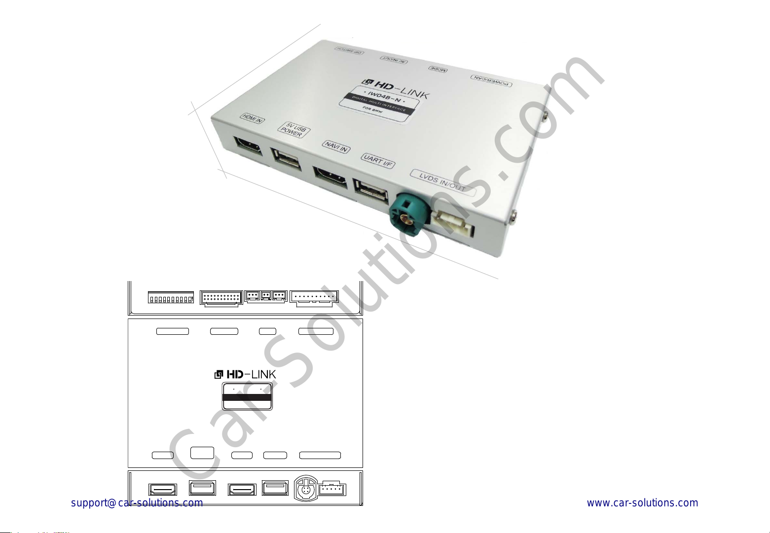
Width: 97 mm
Height: 21 mm
Length: 142 mm
E xterior
ⓐ ⓑ ⓒ
ON 1 2 3 4 5 6 7 8 9 10
AV IN/OUT
iw04b- n
digita l mul t i in t erface
fo r b mw
NAVI IN
UART I/F
HDMI IN
DIP SWITCH
5V USB
POWER
ⓓ
POWER/CAN MODE
LVDS IN/OUT
ⓔ ⓕ ⓖ ⓗ ⓘ ⓙ
ⓐ DIP SWITCH
ⓑ AV IN / OUT
ⓒ MODE
ⓓ POWER / CAN
ⓔ HDMI IN
ⓕ 5V USB POWER
ⓖ NAVI IN
ⓗ UART I/F
ⓘ L VD S IN
ⓙ L VDS OUT
4
Page 4
C omponents
Car-Solutions.com
www.car-solutions.com
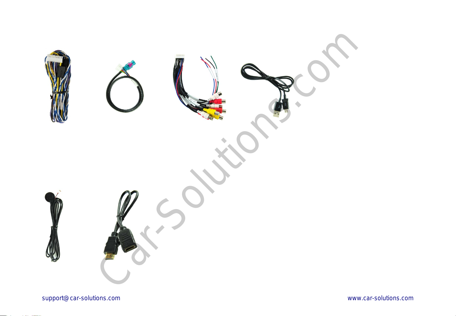
Power / CAN Cable LVDS Cable AV IN / OUT Cable 5-pin Micro USB Cable
Optional Parts
Mode Switch HDMI Extender
(s old s eparately a t the K AP )
(For stick type HDMI device)
5
Page 5
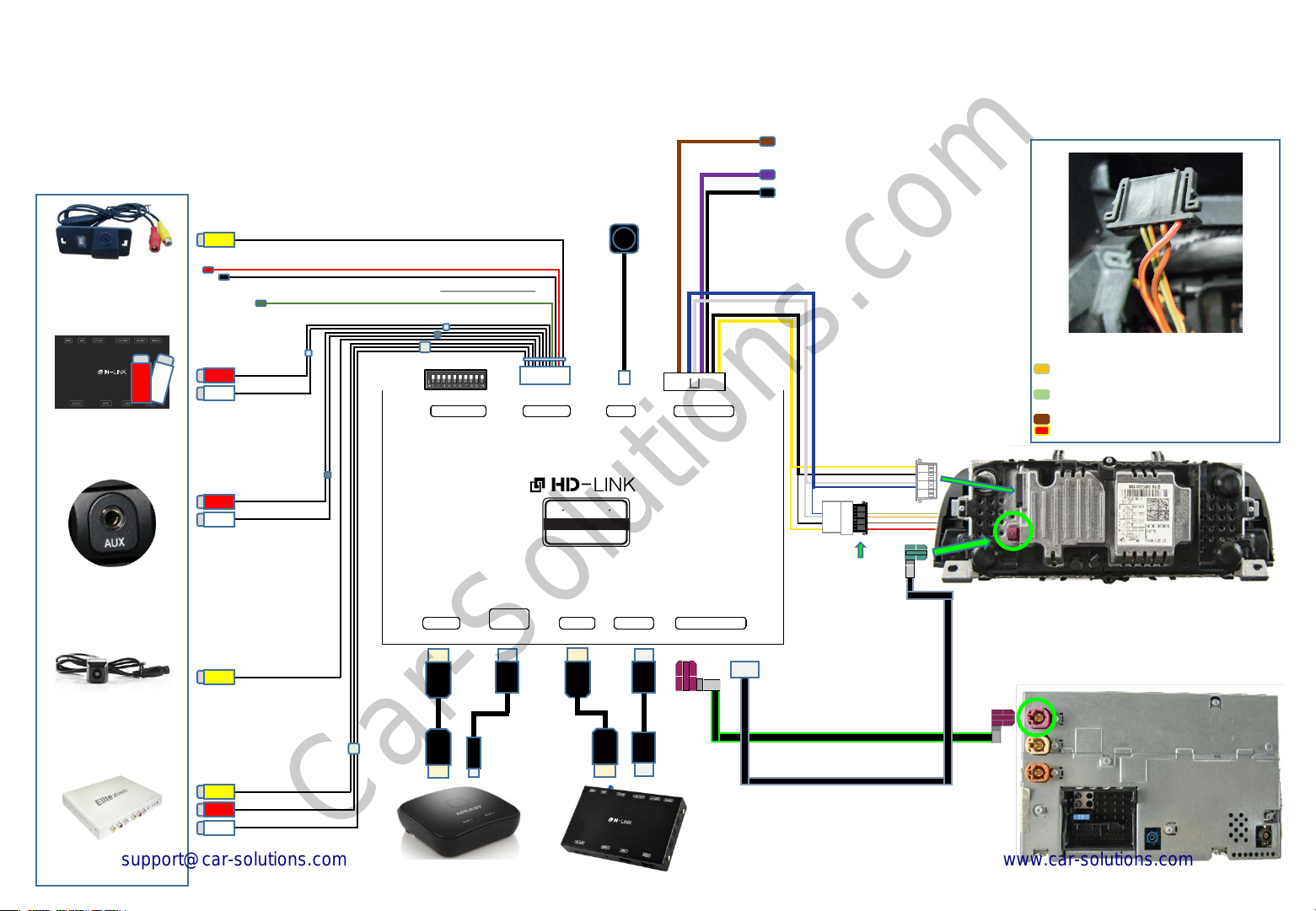
Full Ins tallation Diagram
Car-Solutions.com
www.car-solutions.com
※ Optional External Devices
External Rear View
Camera
Audio(AUX) Output of
Navigation Box
Auxiliary(AUX)
Input of the car
RV-CAM Video Input
12V Power Output & GND Output(RV-CAM Power)
Reverse Signal Detection(opt i onal )
DIP S/W Setting
NAVI Audio Input
Audio Output
HDMI IN
DIP SWITCH
5V USB
POWER
Mode Switch
(optional)
AV IN/OUT
iw04b- n
digit a l mu l t i int er fa ce
f or b mw
NAVI IN
UART I/F
LVDS IN/OUT
IR OUT
NAVI 12V Power Output (ACC 12V OUT)
GND Output(GROUND)
POWER/CAN MODE
Provided Main cable
OEM Main cable
※ CAN HIGH / LOW Pin Specification
1
4
Monitor Main-Harness
Pin # 5 = CAN HIGH (Light green / Orange)
Pin # 11 = CAN LOW (Light green)
Pin # 12 = GND(Brown)
Pin # 15 = Head Unit Power(Red / Yellow)
FV-CAM Video Input
External Front View
(AV1)
Camera
AV device
AV-Input(AV2)
(ex: DTV Box, Divx)
HDMI
HDMI
HDMI Device
USB
HDMI
HDMI
USB
USB
Navigation Box
(Provided LVDS Cable)
OEM Head Unit
(OEM LVDS Cable)
6
Page 6
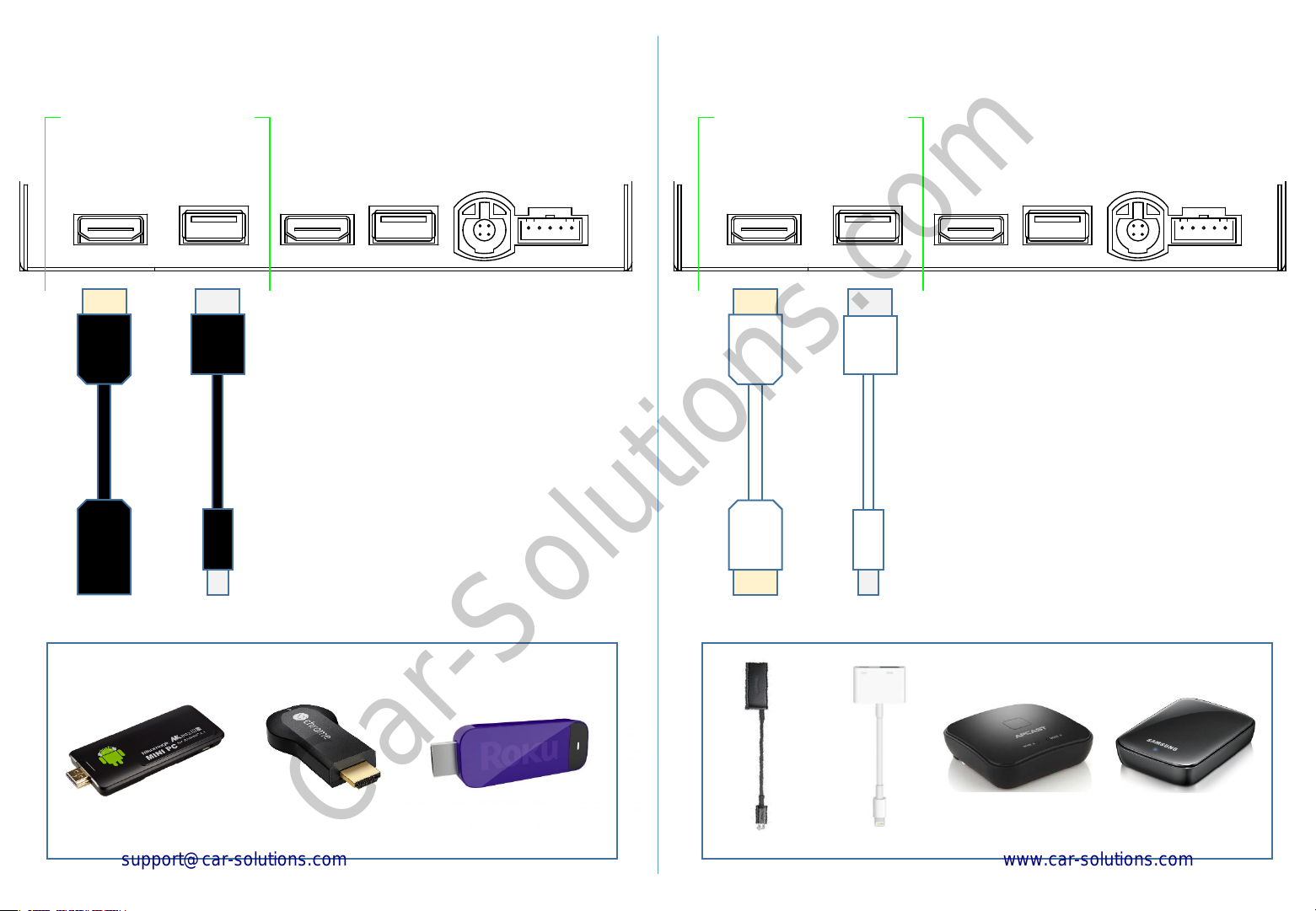
HDMI C onnection Diagram
Car-Solutions.com
www.car-solutions.com
HDMI Device
HDMI Device
HDMI IN
HDMI
HDMI
HDMI
(Female)
(HDMI Extender)
5V USB
POWER
USB USB
(5V-1A Power output for HDMI Device)
‘Stick Type’ HDMI Devices
HDMI IN
HDMI
HDMI
(Male)
(HDMI Cable)
5V USB
POWER
‘Dongle & Adapter’ Type HDMI Devices
(5V-1A Power output for HDMI Device)
7
Page 7
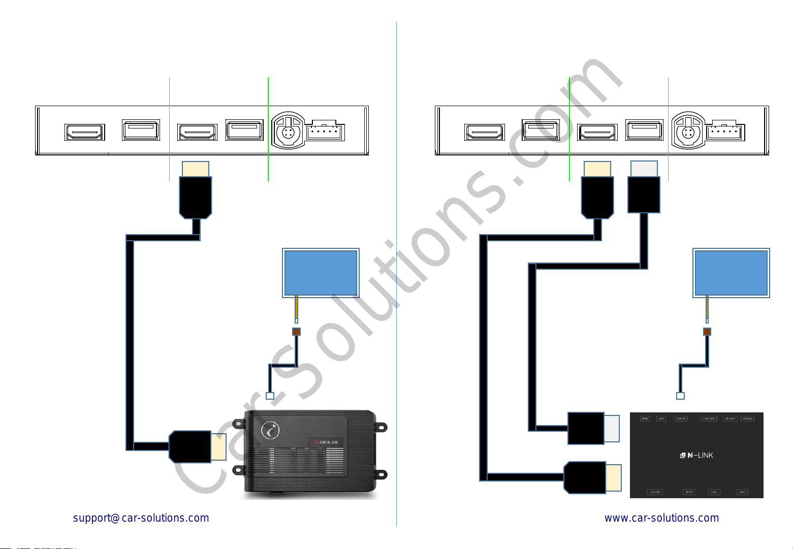
Navigation C onnection Diagram
Car-Solutions.com
www.car-solutions.com
Navigation(GPS) Box
NAVI IN
HDMI
UART I/F LVDS IN / OUT NAVI IN
Touch screen panel
Navigation(GPS) Box
UART I/F LVDS IN / OUT
HDMI
(USB cable connecting is for ‘N-Link’ only.)
USB
Touch screen panel
USB
HDMI
HDMI
iNAVI - CUBE
N-Link or KG-W14H
8
Page 8
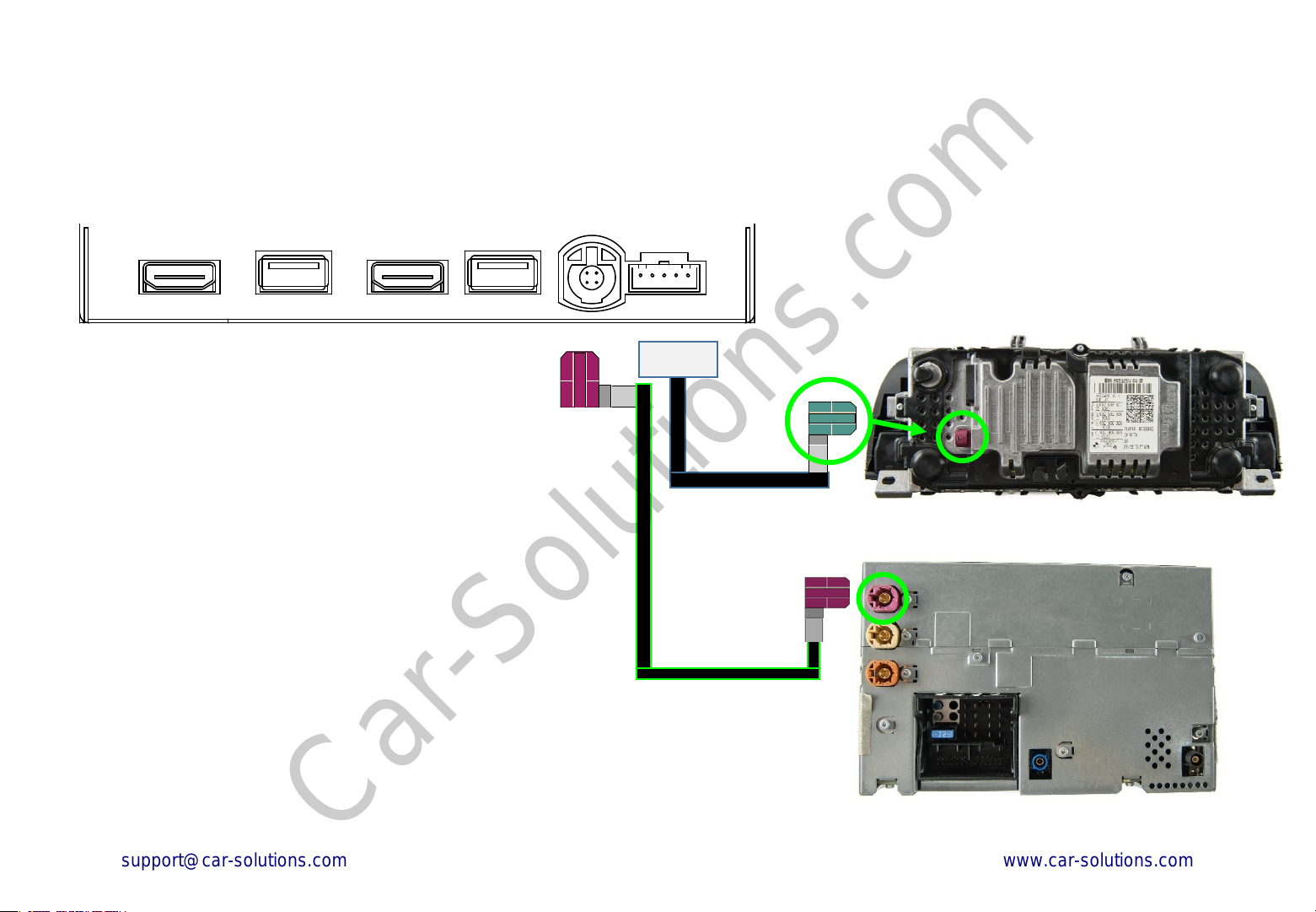
LVDS C onnection Diagram
Car-Solutions.com
www.car-solutions.com
HDMI IN
LCD
Cable
5V USB
POWER
'Genuine(OEM) LVDS connector' should be connected
to IW04B-N LVDS IN / OUT port
‘Provided LVDS connector' should be connected to the
monitor instead to the genuine connector.
NAVI IN UART I/F
LVDS IN / OUT
(OEM LVDS Cable)
Monitor(OEM)
(Provided LVDS Cable)
Head Unit
10
Page 9
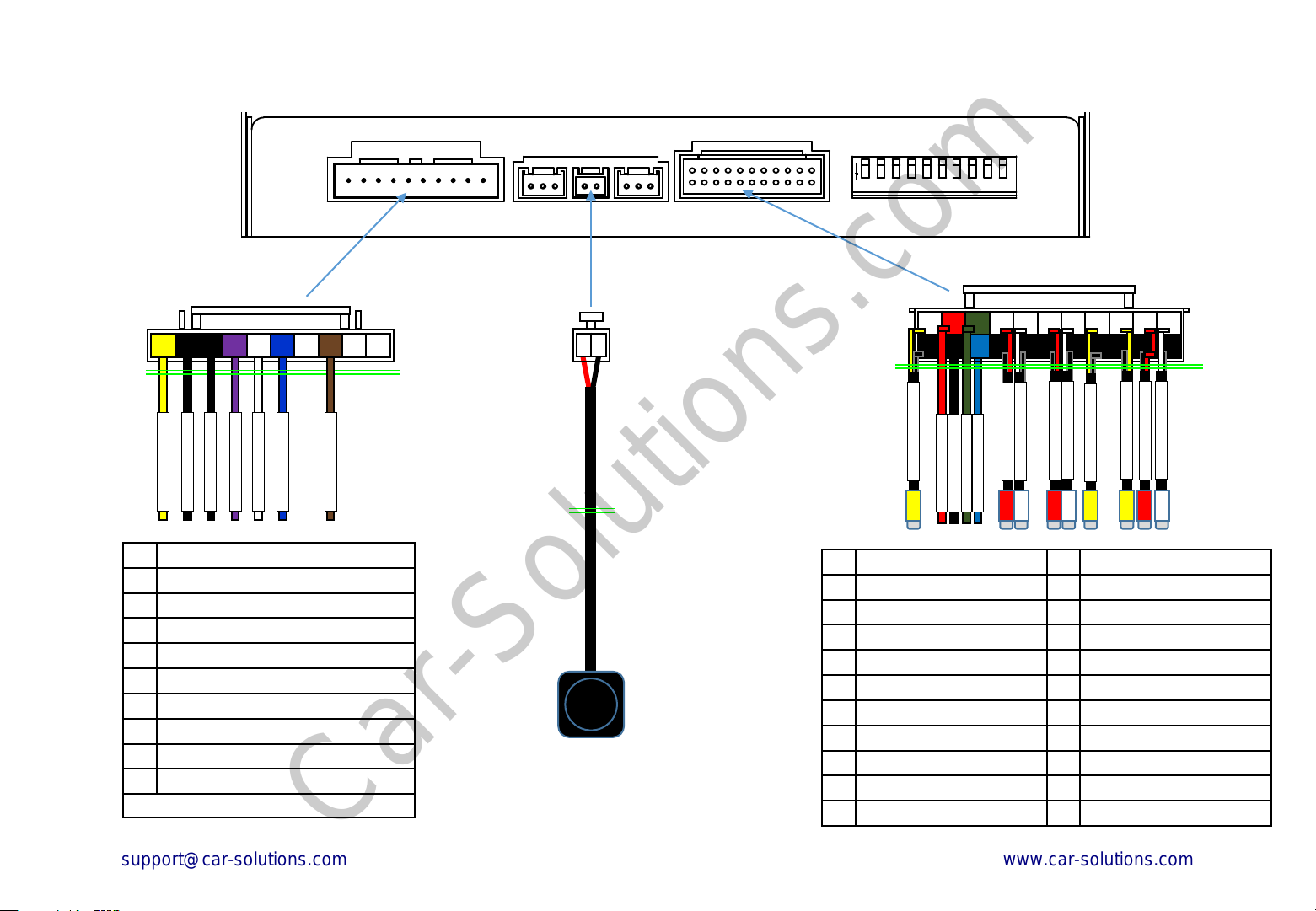
Body Connector specifications
Car-Solutions.com
www.car-solutions.com
POWER / CAN AV IN / OUT DIP SWITCH MODE
1 2 3 4 5 6 7 8 9 10
Length : 100 cm
NAVI 12V OUT
GROUND
GROUND
BAT +
CAN H
IR OUT
CAN L
1 2
Length: 150 cm
ON 1 2 3 4 5 6 7 8 9 10
1 2 3 4 5 6 7 8 9 10 11
12 13 14 15 16 17 18 19 20 21 22
REAR CAMERA
REVERSE 12V IN
REAR 12V
GROUND
IR OUT
Length : 20 cm
NAVI AUD IN R
NAVI AUD IN L
AUDIO OUT R
AUDIO OUT L
AV1 IN V
AV2 IN R
AV2 IN V
AV2 IN L
1 BATTERY POWER INPUT
2 GND INPUT
3 GND OUTPUT
4 ACC(12V) POWER OUTPUT
5 PAS CAN HIGH
6 PAS CAN LOW
7 8 IR OUT
9 -
10 -
• The colors of each wires can be changed under manufacturer’s circumstance
Push Switch
.
1 RV-CAM VIDEO INPUT 12 GND(RV-CAM VIDEO)
2 RV-CAM POWER OUT 13 GND OUTPUT(RV-CAM)
3 REVERSE DETECTION 14 IR OUT
4 NAVI AUX INPUT R 15 GND(NAVI AUX IN R)
5 NAVI AUX INPUT L 16 GND(NAVI AUX IN L)
6 AUDIO OUTPUT R 17 GND(AUDIO OUT R)
7 AUDIO OUTPUT L 18 GND(AUDIO OUT L)
8 AV1 VIDEO INPUT 19 GND(AV1 VIDEO IN)
9 AV2 VIDEO INPUT 20 GND(AV2 VIDEO IN)
10 AV2 AUDIO INPUT R 21 GND(AV2 AUDIO IN R)
11 AV2 AUDIO INPUT L 22 GND(AV2 AUDIO IN L)
12
Page 10
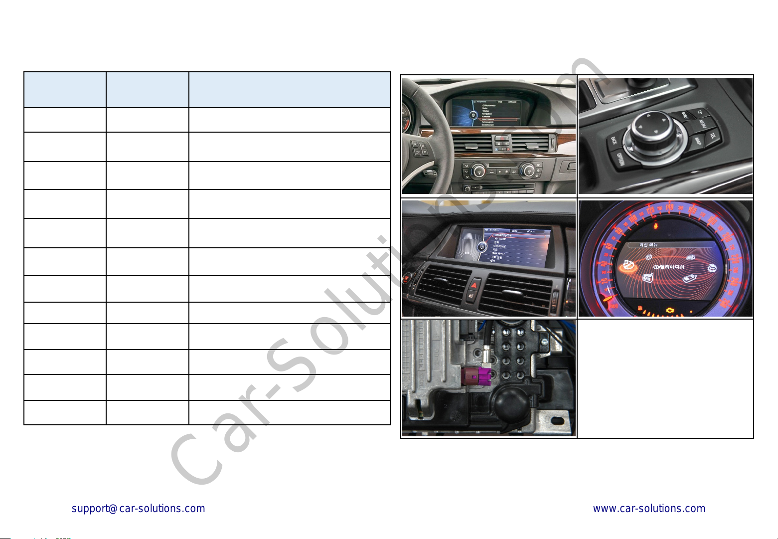
C ar C ompatibility C hart
Car-Solutions.com
www.car-solutions.com
Car Models
3 Series 2009 -2012 E90, E91, E92, E93
5 series 2009 E60,E61
5 series 2009-2012 F10, F11 , F07(5GT)
6 Series 2011 -2012 F12, F13
7 Series 2009 -2013 F01, F02
X1series 2009 - E84
X3 series 2011 - 2013 F25
X5 series 2009 -2013 E70
X6 series 2010 - 2013 E71, E72
Production
Year
Specific Models
The IW04B-N supports the BMW
original screen equipped with
‘4-pin LVDS round connector’ only.
Please check the specification of
original LVDS connector on the
sidelines of a production year.
13
Page 11
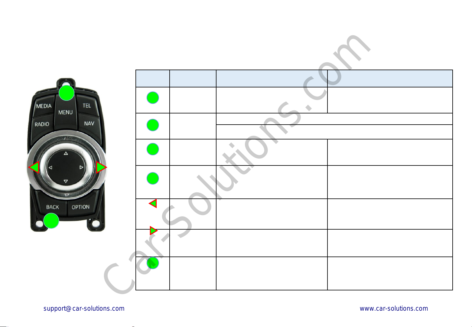
Activation by original buttons of B MW
Car-Solutions.com
www.car-solutions.com
For BMW
Button Function Operation Remarks
1
2
BMW iDrive Controller
1
MENU
1
MENU
1
MENU
1
MENU
LEFT
PUSH
RIGHT
PUSH
2
BACK
Changing
Modes
Shortcut to
each modes
Back to OEM Press the button short. Return to the OEM mode in any modes.
System
Locking /
Unlocking
Changing
mode to Front
View Camera
mode(AV1)
Changing
mode to
PIP(Rear)
Reset to
factory default
setting and
power.
Press the button 2 seconds long. Order: HDMI → NAVI → AV2 → OEM
Press the button 2 times. < OEM → NAVI >
Press the button 4 times. < OEM → AV2 >
If you visit car service center, you can lock
Press the button 10 seconds long.
Changing mode to Front View Camera
mode(AV1)
Push the button right 2 seconds long.
(Only Rear,AV1)
Press the button 10 seconds long.
the all functions of IW04B-N.
It is only possible to use the OEM functions
under it is locked.
Push the button left 2 seconds long.
You can use this function only for 3 modes.
(Full, PIP Mode1, PIP Mode2)
You can use this function when you get in
trouble to see the screen while setting the
screen.
14
Page 12
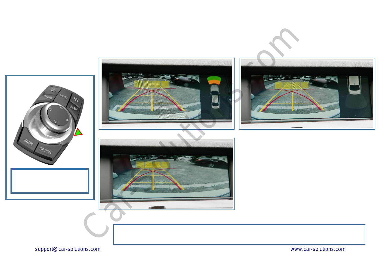
Rear View PIP
Car-Solutions.com
www.car-solutions.com
(External Rear View Camera) *Parking line color change to green color
1. Rear, AV1 PIP MODE
Push the button right 2
!
seconds long
You can use this function only for 3 modes. (Full, PIP Mode1, PIP Mode2)
15
Page 13
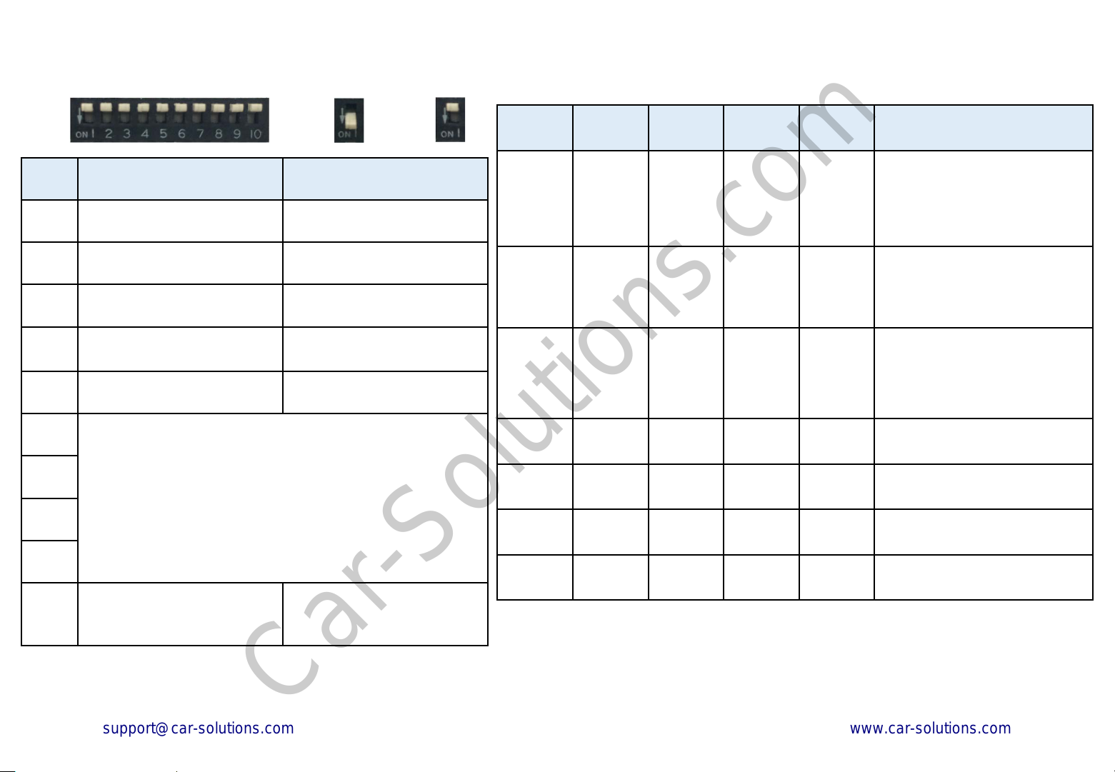
DIP S witc h S ettings
Car-Solutions.com
www.car-solutions.com
OFF
ON
Pin
No.
1
2
3
4
5
6
7
8
ON(▼)
HDMI Mode Skip HDMI Mode
Navigation Mode Skip Navigation Mode
External Rear View Camera Original Rear View Camera
External Front View
Camera
(AV1 Mode)
AV2 Mode Skip AV2 Mode
Selection of car model
ON: ▼
Skip External Front View
Camera
OFF:▲
OFF(▲)
(AV1 Mode)
No.6 No.7 No.8 No.9 No.10 Car Models
5(F10),6(F12),7(F01),
5GT( F07) / 10.2inch
OFF(▲) OFF(▲) OFF(▲) OFF(▲) OFF(▲)
OFF(▲) OFF(▲) OFF(▲) OFF(▲)
OFF(▲) OFF(▲) OFF(▲)
OFF(▲) OFF(▲) OFF(▲)
ON(▼)
ON(▼) ON(▼) MINI Visual Boost / 6.5 inch
ON(▼)
OFF(▲)
X5(E70),X6(E71), E60(Entire
model) / 8.8 inch
5(F10),
6(F12),7(F01),5GT(F07),
(2012 ~ Connect i-drive can)
2010 3(E90), X1,(E84),X3(F25)
2nd Generation i-drive / 8.8
inch
9
10
* Among the BMW models[5 series(F10) and 5 GT(F07)] produced in 2013, most of
them are equipped with 6 pin LVDS monitor connector but some of them are
equipped with 4 pin LVDS monitor connector. Then, you should splice CAN wires
connection under the i-Drive controller, separately.
Connect i-drive can Connect monitor can
16
Page 14
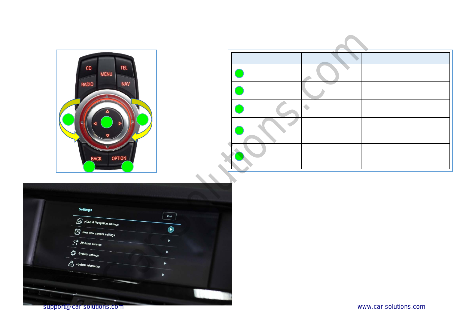
S ettings
Car-Solutions.com
www.car-solutions.com
For BMW
Button Function Operation
4 5
3
2 1
OPTION
1
BACK
2
Selection
3
Turn the dial
4
counterclockwise
Turn the dial
5
clockwise
1. Enter into the s etting menu.
<Press the ‘OPTION’ button 5 seconds long.>
- HDMI & Navigation settings
- Rear view camera settings
- AV-input settings
- System settings
- System information
Enter into the
setting menu
Back to previous
menu
Select the menu
and setting values.
Move the menupointer and adjust
the setting values.
Move the menupointer and adjust
the setting values.
Press the button 5 seconds long.
Press the button short.
Press the button short.
Move the pointer and setting
values to up(↑) and left(←).
Move the pointer and setting
values to down(↓) and right(→).
17
Page 15
설정 메뉴
Car-Solutions.com
www.car-solutions.com
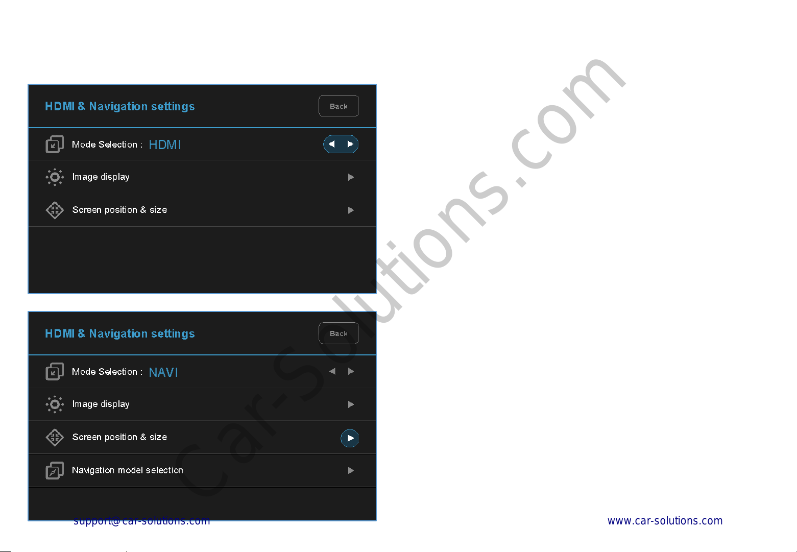
2. HDMI mode s ettings
- Mode selection: HDMI ↔ NAVI
- Image display
= Adjust the values of brightness and contrast
Red-Green-Blue colors of HDMI display.
- Screen position & size
= Entry Disabled / Not applicable.
3. NAVI mode s ettings
- Mode selection: NA VI ↔ HDMI
- Image display
= Adjust the values of brightness and contrast
Red-Green-Blue colors of NAVI display.
- Screen position & size
= Entry Disabled / Not applicable.
- Navigation Resolution selection
① 800 X 480 ② 1280 X 480
18
Page 16

S ettings
Car-Solutions.com
www.car-solutions.com
4. R ear view camera settings
- Parking guide lines
= Adjust position of parking guide lines and
select the lines ‘ON or OFF’.
- Parking distance control
= Adjust the position of parking distance control sensors
to ‘LEFT or RIGHT’ and select the PDC ‘ON or OFF’.
- Image display
= Adjust the values of brightness and contrast
Red-Green-Blue colors of Rear view camera display.
5. AV1(Front view c amera) s ettings
- Mode selection: A V1(Front view camera) ↔ AV2
- Image display
= Adjust the values of brightness and contrast
Red-Green-Blue colors of AV1(Front view camera) display.
- Screen position & size
= Entry Disabled / Not applicable.
- Automatic activation function(A V1)
= * Please refer to next page.
- Parking distance control
= Adjust the position of parking distance control sensors
to ‘LEFT or RIGHT’ and select the PDC ‘ON or OFF’.
19
Page 17
S ettings
Car-Solutions.com
www.car-solutions.com
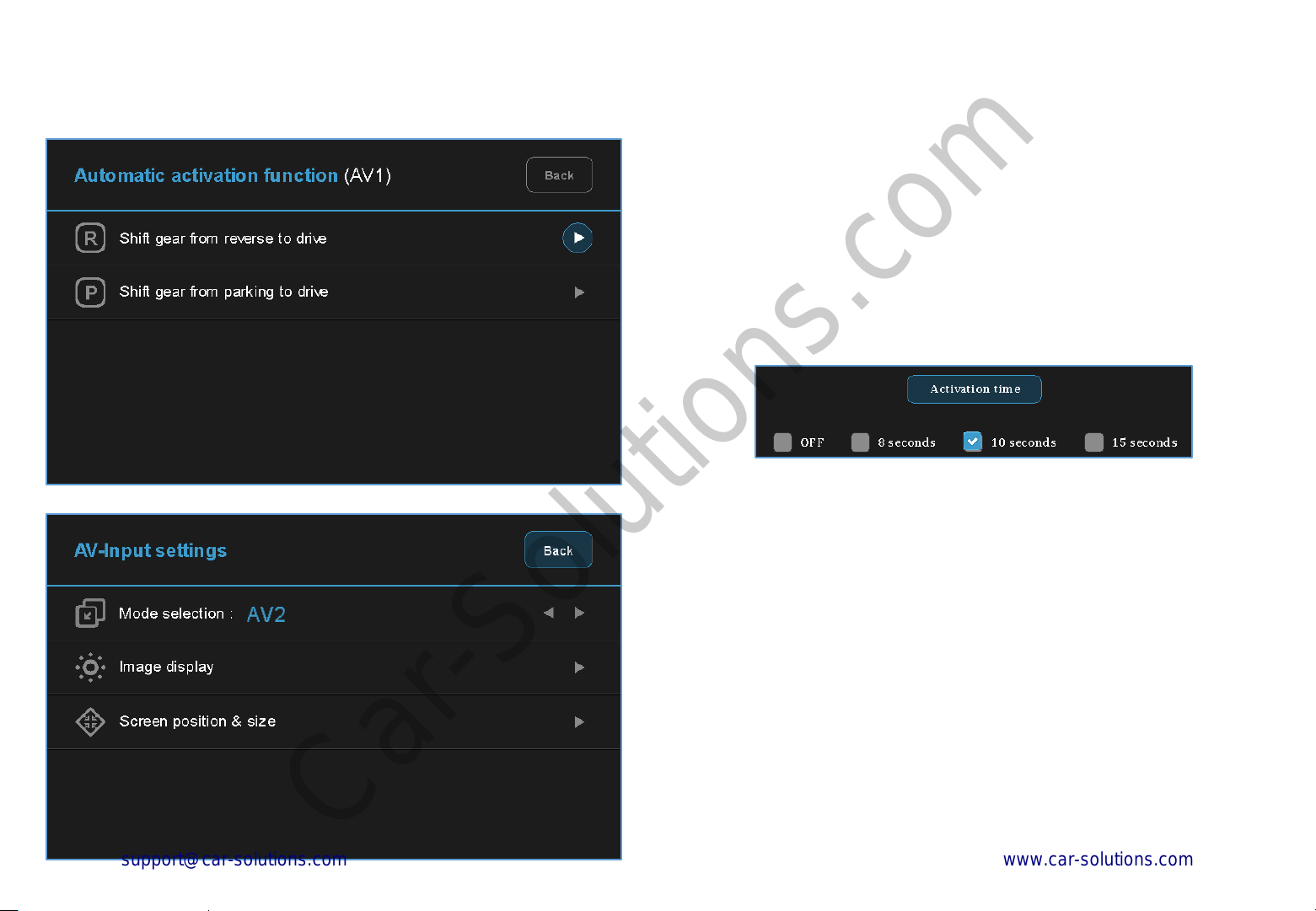
6. Automatic ac tivation func tion(AV1)
- Shift gear from reverse to drive
- Shift gear from parking to drive
* When you shift gear ‘from reverse to drive’ or ‘from parking to drive’,
it just works automatically during the activation time you selected.
7. AV2 s ettings
- Mode selection: A V2 ↔ AV1(Front view camera)
- Image display
= Adjust the values of brightness and contrast
Red-Green-Blue colors of AV2 display.
- Screen position & size
= Entry Disabled / Not applicable.
20
Page 18
S ettings
Car-Solutions.com
www.car-solutions.com
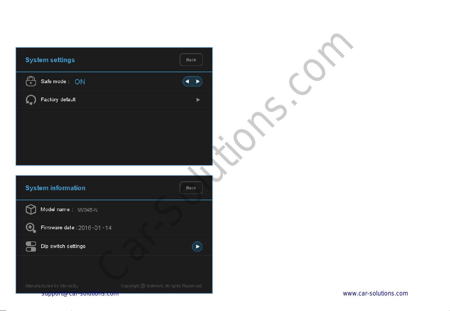
8. S ys tem s ettings
- Safe mode
= Select the one of two between ‘ON and OFF’.
* If you select ‘ON’, 3 modes(HDMI, NAVI and AV2) will be faded out
when the car is driven.
- Factory default
= Reset all setting values to factory default setting.
9. System information
- Mode name : IW04B-N
- Firmware date : 2016 – 01 – 14
- = You can check the current firmware version date.
- Dip switch settings
= You can check the current positions of dip switch settings.
(Latest firmware date)
21
Page 19
S ettings
Car-Solutions.com
www.car-solutions.com
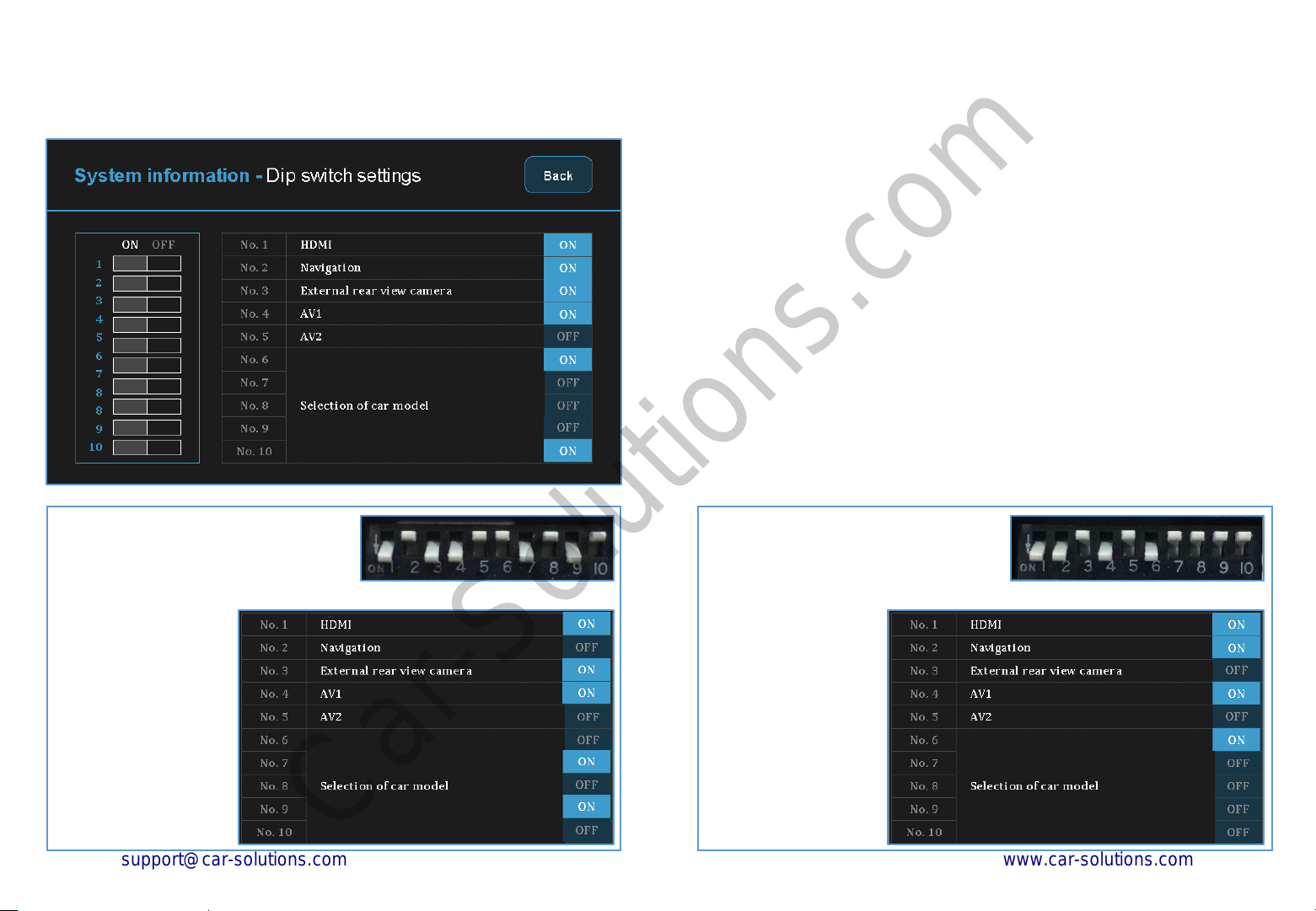
10. Information of Dip s witch s ettings
* You can check the current positions of dip switch settings.
ex 1)
Actual DIP switch values. (→)
Appears on the setting menu. (↓)
ex 2)
Actual DIP switch values. (→)
Appears on the setting menu. (↓)
22
 Loading...