

Page 1

Mesh Gateway
HDL-MCIP-RF.10
www.hdlautomation.com
User Manual
Page 2

User Manual
HDL-MCIP-RF.10
Mesh Gateway – User Manual
INDEX
1. Overview
........................................................................................................................................
1
1.1 General Information
...........................................................................................................
1
1.1.1 Description
...............................................................................................................
1
1.1.2 Mounting
..................................................................................................................
1
1.2 Functionalities Description
...............................................................................................
1
1.3 Device Description
.............................................................................................................
2
2. Safety Instructions
........................................................................................................................
3
3. Technical Data
..............................................................................................................................
3
4. Installation
......................................................................................................................................
4
4.1 Wiring
...................................................................................................................................
4
4.2 HDL Bus Pro Description
..................................................................................................
5
5. Wireless System Introduction
.....................................................................................................
5
5.1 Mesh Mode
.........................................................................................................................
5
5.1.1 Wiring Diagram
.......................................................................................................
5
5.1.2 Basic Configuration Steps
.....................................................................................
6
5.2 Bridge Mode
........................................................................................................................
7
5.2.1 Wiring Diagram
.......................................................................................................
7
5.2.2 Basic Configuration Steps
.....................................................................................
7
6. Software Configuration
................................................................................................................
8
6.1 Basic Setting
.......................................................................................................................
8
6.1.1 Change the ID
.........................................................................................................
8
6.1.2 Change the IP and IP MAC
..................................................................................
8
6.2 Network Information
..........................................................................................................
8
6.2.1 Connection Preferences
........................................................................................
8
6.2.2 Wireless Information
............................................................................................
17
6.3 Filter
...................................................................................................................................
17
6.3.1 Network Style
........................................................................................................
17
6.3.2 Options of RF Filter
..............................................................................................
18
6.4 Node Configuration
..........................................................................................................
19
7. Note
..............................................................................................................................................
23
Page 3

User Manual
HDL-MCIP-RF.10
Mesh Gateway – User Manual
1
1. Overview
1.1 General Information
1.1.1 Description
HDL-MCIP-RF.10 is a gateway based on IEEE802.15.4 standard MESH technology.
Mesh Wireless Gateway has three communication interfaces: RJ45, HDL Buspro, RF,
which can interconnect different media platforms(Ethernet, RS485, RF) of HDL intelligent
devices. It’s very useful in the renovation projects and in the inconvenient of layout
application environment.
1.1.2 Mounting
Desk or Wall Mounted
1.2 Functionalities Description
Can be configured as Mesh mode
Can be configured as Bridge mode
Communication data rate is higher than the cable
Page 4

User Manual
HDL-MCIP-RF.10
Mesh Gateway – User Manual
2
1.3 Device Description
○
a
. Programming Button:
Long press the ‘PROG’ button
10s, then its IP and IP MAC will
be reset to the factory settings.
○
b
. Antenna: transmit and receive
wireless signals
○
c
. RJ45: Ethernet port RJ45
○
d
. DC24V: Power Supply, no
need to use it if connected the HDL
Bus interface (the DC power is
provided from it)
○
f
.MODE LED: RED LED flashing
quickly under wireless setup mode;
GREEN LED flashing when network
jams.
○
g
. T/R LED: BLUE LED flashing
when transmitting or receiving the
wireless signal.
Page 5

User Manual
HDL-MCIP-RF.10
Mesh Gateway – User Manual
3
2. Safety Instructions
Do not make wrong connection on Bus interface, it will damage the Bus interface of
this module.
Never let liquids get into the module, it will damage this device.
Do not get AC240V voltage into Bus wire, it will damage all devices in the system.
Ensure good ventilation.
3. Technical Data
Electric Parameters:
Working power
12~30VDC
Communication
RJ45, HDL-BUS, RF
Wireless transmit power
+10dbm
Wireless receive sensitivity
-90dbm
Communication distance indoor
50m (barrier free)
Work mode
Mesh mode, Bridge mode
BUS Terminal
Wago 252,0.75-0.85mm Diameter Single Core
Wireless central frequency
(China) WPAN
780MHz-786MHz
(Europe) SRD
864MHz-870MHz
(North America) ISM
904MHz-928MHz
Environmental Conditions:
Working Temperature
0℃~45℃
Working relative Humidity
Up to 90%
Page 6

User Manual
HDL-MCIP-RF.10
Mesh Gateway – User Manual
4
Storage Temperature
-20℃~+60
℃
Storage relative Humidity
Up to 93%
Approve:
CE
RoHS
Production Information:
Dimension
107×99.5×27(mm)
Weight
103g
Housing material
ABS
Installation
Desk or Wall Mounted
Protection Degree
IP20
4. Installation
4.1 Wiring
Page 7

User Manual
HDL-MCIP-RF.10
Mesh Gateway – User Manual
5
4.2 HDL Bus Pro Description
Connector Information
buspro
DC24V
Red
COM
Black
DATA -
White
DATA +
Yellow
5. Wireless System Introduction
In the wireless system, use mesh gateway (HDL-MCIP-RF.10) to manage all the wireless
devices, the gateway can work in mesh mode and bridge mode.
5.1 Mesh Mode
5.1.1 Wiring Diagram
The mesh mode can realize the communication between the HDL Buspro devices and the
RF devices.
In mesh mode, must set different frequency (RF Channel) for each gateway, each
gateway manages a wireless network with same Subnet ID of the RF devices.
Page 8

User Manual
HDL-MCIP-RF.10
Mesh Gateway – User Manual
6
5.1.2 Basic Configuration Steps
Basic steps to build up the mesh mode system:
1- Select the free frequency for the gateway, HDL-MCIP-RF.10
For China, select WPAN band, and the range of frequency is 780MHz -786MHz;
For Europe, select SRD band, and the range of frequency is 864MHz – 870MHz;
For North America, select ISM band, and the range of frequency is 904MHz – 928MHz .
2- Set the unique PSK PWD for the gateway
Must set the unique password for your gateway, then even other RF systems use same
frequency as yours, but cannot control your system devices because of different PSK
PWD.
3- All wireless devices enter the wireless setup mode
The way to enter the wireless setup mode:
Gateway:
Press the ‘PROG’ button 3 times continuously or enter from HDL BUS software directly, its
LED will flash quickly
Curtain:
Press the ‘PROG’ button 3 times continuously, its LED will flash quickly.
DLP Panel:
Long press the first and eighth buttons at the same time to enter the setting page, select
‘WIRELESS’, the seventh and eighth buttons’ LED will be on.
Normal Panel:
Long press any button of it about 25s (at the 15s, the LED will flash quickly that means it
enters the address modify mode), the LED will flash slowly.
4- Set the wireless parameters for normal wireless devices
In the HDL BUS software, set the ID, frequency and PSK PWD for the normal wireless
devices (panel, relay, etc) via the mesh gateway. Their Subnet ID, frequency and PSK
PWD must be same as the gateway’s, otherwise the gateway cannot manage them.
Page 9

User Manual
HDL-MCIP-RF.10
Mesh Gateway – User Manual
7
5- All devices exit the wireless setup mode
You are able to search and configure these wireless devices normally via the gateway
now.
5.2 Bridge Mode
5.2.1 Wiring Diagram
In bridge mode, RS485 and Ethernet data in multiple gateways can be transmitted via RF,
which effectively extends the communication distance. In the inconvenient of layout
application environment, different subnets can be interconnected.
5.2.2 Basic Configuration Steps
Basic steps to build up the bridge mode system:
1- All gateways use different Subnet ID
2- All gateways use same frequency
3- All gateways use same PSK PWD
Important Note: RF reliable transmission distance is 50m, obstacles will reduce the
transmission distance, the distance decreases 20m if through a wall, so it is better to
install mesh wireless devices in empty place and forbid to install near to the metal objects,
in order to get a good communication quality, this device is not recommended to install in
electric box, if have to, then please add an antenna outside.
Page 10

User Manual
HDL-MCIP-RF.10
Mesh Gateway – User Manual
8
6. Software Configuration
6.1 Basic Setting
6.1.1 Change the ID
Set the Subnet ID for the gateway, all the wireless gateways’ Device ID is 0, can not be
changed.
6.1.2 Change the IP and IP MAC
Change the default IP and IP MAC, to avoid possible conflict
Default IP: 192.168.10.250, Default MAC: H-D-L-85-85-85
6.2 Network Information
6.2.1 Connection Preferences
This gateway supports remote control, and it supports three communication modes, they
are: Local Network, P2P and Remote Server.
Page 11

User Manual
HDL-MCIP-RF.10
Mesh Gateway – User Manual
9
- Local Network
It works as a normal gateway between the RF and local Ethernet. This mode does not
have the remote function.
Configuration steps:
1. Change the default IP and IP MAC, to avoid possible conflict.
Default IP: 192.168.10.250, Default IP MAC: H-D-L-85-85-85
2. Select ‘Local Network’ (all other tables will not be available.) and click Apply.
Page 12

User Manual
HDL-MCIP-RF.10
Mesh Gateway – User Manual
10
- P2P
In this mode, you are able to access the wireless system directly through Internet, using
HDL-BUS Pro software, without any help from HDL server.
Configuration steps:
1. Change the default IP and IP MAC, to avoid possible conflict.
Default IP: 192.168.10.250, Default IP MAC: H-D-L-85-85-85
Page 13
User Manual
HDL-MCIP-RF.10
Mesh Gateway – User Manual
11
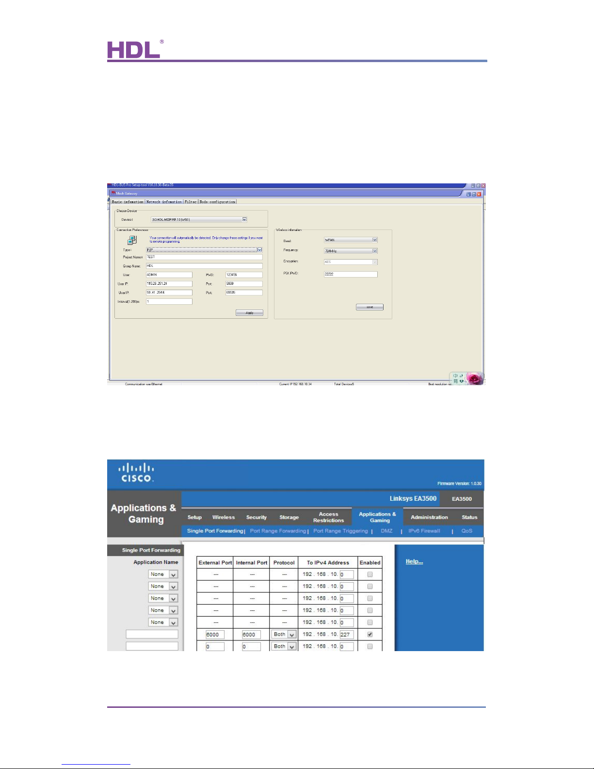
2. Select “P2P”, fill in “Project Name”, “Group Name”, “User”, “PWD”. The “User IP” is the
public IP of Router R2 (see diagram above), the “Port” is the one you are going to fill in the
Router R2 when setting up port forwarding. Some routers support Internal port and
External port mapping, some do not, there is only one port, or you can take it as External
port equals Internal port, to simplify, we suggest to use the port 6000 for all ports.
3. Configure port forwarding in Router R1
Map UDP port 6000 to the IP of mesh gateway
Page 14

User Manual
HDL-MCIP-RF.10
Mesh Gateway – User Manual
12
4. Configure port forwarding in Router R2
Map UDP port 6000 to the IP of PC/laptop that runs HDL-BUS Pro Setup Tool.
5. Run HDL-BUS Pro Setup Tool on the PC/laptop with the IP set in the Router R2, in this
doc, it is 192.168.1.100.
6. Select ‘Internet’, in the pop up window below select “P2P” and fill in the “Group Name”,
“Project Name”, “User”, “Password”. The “IP” is the public IP of Router R1, the “Port” is the
one set in Router 1, the UDP 6000.
Page 15

User Manual
HDL-MCIP-RF.10
Mesh Gateway – User Manual
13
7. Click “Apply”, this pop up window will disappear when you connect to the remote
SB-DN-1IP successfully, then you can search for devices and configure them as usual.
Page 16

User Manual
HDL-MCIP-RF.10
Mesh Gateway – User Manual
14
- Remote Server
This mode is suitable for both travelling programmer and end user to configure and control
HDL wireless system via Internet. Since a server is getting involved in this mode, no static
public IP is needed for HDL wireless system because the HDL-MCIP-RF.10 in Remote
Server mode will keep updating itself to the server, programmer and end user can always
get info of the remote HDL-MCIP-RF.10 from the server and later access the HDL wireless
system directly.
Schematic diagram:
Configuration steps:
1. Change the default IP and IP MAC, to avoid possible conflict.
2. Set your Project Name, Group Name, User, PWD and click Apply.
Page 17

User Manual
HDL-MCIP-RF.10
Mesh Gateway – User Manual
15
Server
HDL server has a fixed IP and port, 115.29 .251.24:9999 or 59.41.254.6:9999, do not
change it, it is editable because HDL may change the server or help installation
companies to build their own servers in the future, in that case, the installation companies
can fill in their own servers and ports.
“Interval(1-255)m ”
It is the parameter that decides how long the HDL-MCIP-RF.10 will register its info to the
HDL server again, e.g., if we set it as 2 minutes, that means every 2 minutes the
HDL-MCIP-RF.10 will register itself to the HDL server (so that HDL server knows where
this HDL-MCIP-RF.10 locates even if the public IP of the router is changed or private IP of
the HDL-MCIP-RF.10 is changed). Recommend to set it no more than 3 minutes.
Note:
a) ‘Enable DHCP’ is an option that will be supported in the future.
b) Can have 4 active connections, which means when you are configuring the HDL
wireless system, up to 3 people can operate the HDL wireless system from iPad,
android pad at the same time.
3. Exit HDL-BUS Pro Setup Tool and find another Internet access that has a different
public IP for your PC/laptop, run the HDL-BUS Pro Setup Tool again and select ‘Internet’.
Page 18

User Manual
HDL-MCIP-RF.10
Mesh Gateway – User Manual
16
4. Fill the Group Name and sever IP , Click the search button on the pop up window, HDL
server will feedback all projects in the same group (An installation company can have
many projects in different sites) then select your project and fill in the password.
5. Or you can just click the Apply button; this pop up window will exit automatically if it
communicates with remote HDL wireless system successfully, now you can get start to
program the HDL wireless system.
Page 19

User Manual
HDL-MCIP-RF.10
Mesh Gateway – User Manual
17
6.2.2 Wireless Information
Must select free RF frequency for different countries:
For China, select WPAN band, and the range of frequency is 780MHz - 786MHz;
For Europe, select SRD band, and the range of frequency is 864MHz - 870MHz;
For North America, select ISM band, and the range of frequency is 904MHz - 928MHz.
Users could set new wireless transmission password before installation, here we set the
PSK PWD as ‘22222’
6.3 Filter
6.3.1 Network Style
Network Style
Set the working mode for the gateway, mesh mode or bridge mode.
Target subnet ID through (BUS)
This option is used to allow the mesh gateway to transmit the commands from the
Page 20

User Manual
HDL-MCIP-RF.10
Mesh Gateway – User Manual
18
specified Subnet ID device in HDL BUS system. It’s white list. E.g. if select 4 for it, the
gateway will filter all other devices’ commands except the Subnet 4’s, then to reduce the
communication burden of Subnet 4.
For the beginning to configure the system, normally select ‘All Through’ for it; after that,
better to select the specified Subnet ID for the mesh gateway according to the situation.
Note: Only the mesh mode displays this option.
6.3.2 Options of RF Filter
Those RF devices’ commands which enabled in below table will be filtered by the gateway.
The limitation can be specific to Source address, Command and Destination address. It’s
black list.
Note: Only the mesh mode displays this option.
Page 21

User Manual
HDL-MCIP-RF.10
Mesh Gateway – User Manual
19
6.4 Node Configuration
This page is used to set the wireless parameters for the normal wireless devices via the
gateway, all wireless devices need to enter the wireless setup mode. It’s the preparatory
work before user can manage the wireless system, after that can start to search and
configure them as usual.
Take the wireless DLP panel as an example:
1- Click ‘Search’ button
2- You will be able to find the connected mesh gateway in ‘Mesh’ list, and the right side
displays the information of it (Band, Frequency and PSK PWD).
3- Click ‘Enter Gateway Setup Mode’ (or press the ‘PROG’ button 3 times continuously),
the RED LED will flash quickly that means the gateway enters the wireless setup mode.
4- Long press the DLP first and eighth buttons at the same time to enter the setting page,
Page 22

User Manual
HDL-MCIP-RF.10
Mesh Gateway – User Manual
20
select ‘WIRELESS’, then it will enter the wireless setup mode
5- Click the ‘Search’ button again, this panel will be found in the ‘Node’ list.
RSSI: normal range is 0-90, the smaller the better. If it’s larger than 90, that means
the signal is too weak so need to change its installation place, near to other wireless
devices.
6- Select the node, change its ID and remark it, click Save. (the Subnet ID must be same
as the gateway’s)
7- Click ‘Modify Settings of Selection’, and it will show ‘configure successfully ’, then all its
wireless parameters will follow the gateway’s (Band, Frequency and PSK).
8- Click ‘all Node Exit Setup’, then the gateway and the panel will exit the wireless setup
mode.
Page 23

User Manual
HDL-MCIP-RF.10
Mesh Gateway – User Manual
21
9- Go to the HDL BUS setup tool’s main interface to search and add the wireless devices,
start to configure them via the gateway.
Page 24

User Manual
HDL-MCIP-RF.10
Mesh Gateway – User Manual
22
Document updates:
Version
Data
Description
V1.0
2015.02.10
Create new document
Page 25

User Manual
HDL-MCIP-RF.10
Mesh Gateway – User Manual
23
7. Note
……………………………………………………………………………………………………….
………………………………………………………………………………………………………
………………………………………………………………………………………………………
………………………………………………………………………………………………………
………………………………………………………………………………………………………
………………………………………………………………………………………………………
………………………………………………………………………………………………………
………………………………………………………………………………………………………
………………………………………………………………………………………………………
………………………………………………………………………………………………………
………………………………………………………………………………………………………
………………………………………………………………………………………………………
………………………………………………………………………………………………………
………………………………………………………………………………………………………
………………………………………………………………………………………………………
………………………………………………………………………………………………………
………………………………………………………………………………………………………
………………………………………………………………………………………………………
………………………………………………………………………………………………………
………………………………………………………………………………………………………
………………………………………………………………………………………………………
………………………………………………………………………………………………………
………………………………………………………………………………………………………
………………………………………………………………………………………………………
………………………………………………………………………………………………………
………………………………………………………………………………………………………
………………………………………………………………………………………………………
 Loading...