

Page 1
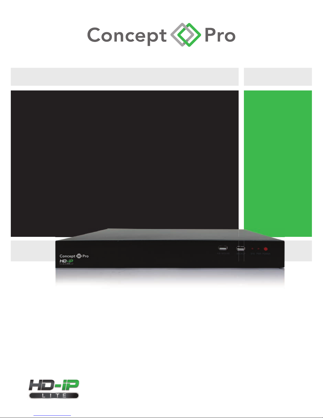
VHDIPL-8
8 CHANNEL NVR
PLUG & PLAY
USER MANUAL
Page 2
i
About this document
Purpose
This document is for the VHDIPL-8, including the product features, hardware
installation, network access, network configuration, daily maintenance, and
troubleshooting.
Intended Audience
This document is intended for:
Technical Support Engineer
Maintenance Engineer
End User
Symbol Conventions
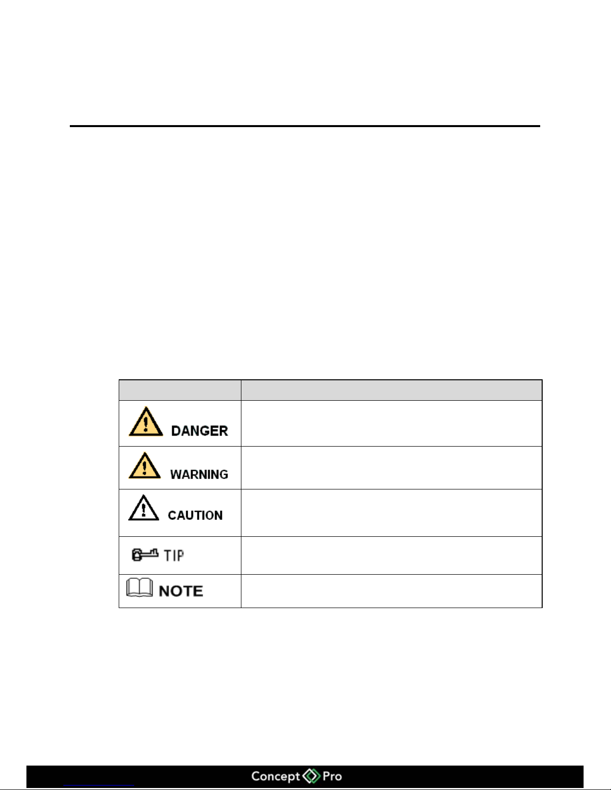
This symbol may be found in this document and are defined as follows:
Symbol
description
Alerts you to a high risk hazard that could, if not avoided,
result in moderate or minor in injury.
Alerts you to a medium or low hazard that could, if not
avoid, result in moderate or minor in injury.
Alerts you to a potentially hazardous situation that could, if
not avoid, result in damage, data loss, performance
deterioration, or unanticipated results.
Provide a tip that may help you solve a problem or save
time.
Provides additional information to emphasize or
supplement important points in the main text.
Page 3

ii
Contents
About this document ................................................................................................... i
1 Preface ........................................................................................................................ 1
1.1 Important note ................................................................................................................ 1
1.2 Check the installation environment ................................................................................ 2
2 Specification ............................................................................................................. 3
3 VHDIPL Networking solutions ............................................................................ 5
4 Installation ................................................................................................................ 6
4.1 Estimated Storage Times ................................................................................................ 6
4.2 Front panel description ................................................................................................... 7
4.3 Rear panel description .................................................................................................... 7
4.4 First boot ........................................................................................................................ 9
4.5 Shutdown ..................................................................................................................... 10
4.6 Display resolution adjustment ...................................................................................... 10
4.7 Add network cameras ................................................................................................... 12
4.8 Login ............................................................................................................................ 13
5 Quick configuration .............................................................................................. 14
6 Live video ................................................................................................................ 18
7 Playback................................................................................................................... 22
7.1 Recording playback ...................................................................................................... 22
7.2 Recording backup ......................................................................................................... 23
8 Alarm searching ..................................................................................................... 27
9 Setup ........................................................................................................................ 29
9.1 VHDIPL setup .............................................................................................................. 29
9.2 Camera management .................................................................................................... 41
10 Web Browser Access for VHDIPL .................................................................... 42
10.1 Login .......................................................................................................................... 42
10.2 Operation Read ........................................................................................................... 43
10.3 Live video................................................................................................................... 45
10.4 Playback ..................................................................................................................... 46
10.5 Alarm search ............................................................................................................... 48
Page 4

iii
10.6 VHDIPL setup ............................................................................................................ 49
10.7 Network camera setup ................................................................................................ 50
11 HD-IP Access for VHDIPL ................................................................................. 51
11.1 Start and run ............................................................................................................... 51
11.2 Login .......................................................................................................................... 51
11.3 System main interface ................................................................................................ 52
11.4 VHDIPL management ................................................................................................ 52
11.5 Playback ..................................................................................................................... 61
12 NVR Client………………………………………….……………………………63
12.1 Start and Run…………………………………………………………………………63
12.2 Login………………………………………………………………………………….63
12.3 System Main Interface………………………………………………………………..63
12.4 System Management………………………………………………………………….64
12.5 Live Video Playback…………………………………………………………….……68
13 HD-IP Lite App .................................................................................................... 70
13.1 HD-IP Lite Android Device………………………………………………………......70
13.2 HD-IP Lite iOS Device…………………………………………...…………………..71
14 F.A.Q....................................................................................................................... 72
Page 5

1
1 Preface
1.1 Important note
Thank you for choosing the Concept Pro VHDIPL Network Video Recorder
(NVR). Please read this user manual carefully before installing the VHDIPL.
Never open or disassemble the device unless it is by a qualified or professional
person, as this product maybe damaged or cause electrical shock.
Video data loss caused by installation, configuration, improper operations, and hard
disk error is not the responsibility of the manufacturer.
Warranty will be void if the “void if broken” sticker is broken.
Page 6
2
1.2 Check the installation environment
Installation environment
Before installing the device, check the installation environment according to Table 1-1
Table 1-1 Installation environment check items
Check item
standard
Moisture-resistant
The relative environment humidity must be in the range of 0%
to 95%. If the humidity is higher than 95%, a dehumidifier must
be installed, such as an air conditioner with the
dehumidification function or a dedicated dehumidifier. In
addition, water seepage, water dropping, and dew forming will
cause damage and will not be covered under the warranty.
Dustproof
The VHDIPL should be installed in a dust free environment to
minimise mechanical breakdown.
Light
The device must be not be installed in direct sunlight.
Installation notice
During the installation, please note:
VHDIPL power input voltage is AC110/220V, 47-63Hz.
VHDIPL should be kept horizontal.
VHDIPL shouldn't be installed in high temperature environments.
Make sure the VHDIPL is connected with other equipment correctly.
Others
Please use a soft dry cloth to clean the VHDIPL, do not use chemical solvents.
Do not place items on top of the VHDIPL.
Page 7
3
2 Specification
System
CPU
SOC
Operating system
Embedded Linux 2.6
Features
Embedded CMS system, user friendly interface, easy to use
Quick configuration and simple operation.
Plug-and-play, auto detection and schedule setup.
Real-time fault alarm mechanism for timely reporting of hard disks, networks, fault
information. Embedded Web Server using Flash technology to support common
browsers with real-time monitoring and playback.
Video
Record Info
8ch recording, Maximum recording Bandwidth is 36 Mbps
Support resolution: 1080P, 720P and D1
Ability to decode
H.264 (ISO / IEC 14496-10) high profile 4.2
4ch up to 1080P playback
Real-time video
Single screen: 1 x 1080p/720p/D1 resolutions with tour
Quad display of 1080p/720p/D1 resolutions
Split screen 1/4/6/8/9 for D1 resolutions
Output
1 x VGA and 1 x HDMI output and can be displayed at the same time
Storage
HDD
2 hard disk, maximum 2 x 4TB hard drive supported
Audio
In / Out
3.5mm linear audio output
Page 8
4
Audio formats
G711_A,G711_U
Network
Transmission control
Embedded network bandwidth adaptive flow control technology.
Interface
2 RJ45 10M/100Mbps network port.
Web
Web server supported with Flash technology for and popular browsers in real-time
monitoring, video playback, and system configuration.
Network protocol
RTP/RTCP, TCP/UDP, ONVIF, HTTP, DHCP, DNS Client, RTMP for Flash Video
Characteristic
Temperature
Ambient temperature: 0 ° C -45 ° C, using industrial grade microprocessor, intelligent
heating and cooling.
Humidity
0% to 90%
Power consumption
Low-power design, motherboard max power consumption 8W; with 2 x 3TB hard disk
increases 40W power consumption.
Power input
AC110/220V, 47-63Hz.
Thermal
The main chip heat sink, plus intelligent temperature controlled fans.
Size
Chassis:372mm x 300mm x 45mm(L x W x H)
Weight
2.23Kg No HDD installed.
USB
2x USB 2.0 interface, respectively as a backup and USB mouse.
Page 9
5
3 VHDIPL Networking solutions
The VHDIPL has 9 Ethernet ports, one is RJ45 without POE, others are POE supported
ports. The 8 POE ports are for connecting to the cameras. Cameras should not exceed a
distance of 100 metres from the POE Ports.
POE port
The POE ports on the VHDIPL can connect to the cameras directly. The VHDIPL will
add the cameras automatically if connected to the POE ports and the default recording
is 24 hours * 7 days a week. Note the POE only supports IEEE 802.3af standard .
10M/100Mbps RJ45 Internet port
When connecting to the Internet or local network, the VHDIPL needs a CAT5 cable
running to a switch or router at a distance of less than 100 metres.
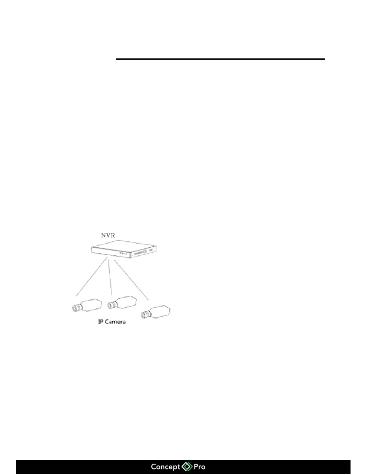
The camera dedicated network topology is shown in Figure 3-1
Figure 3-1 camera dedicated network
Page 10
6
4 Installation
4.1 Estimated Storage Times
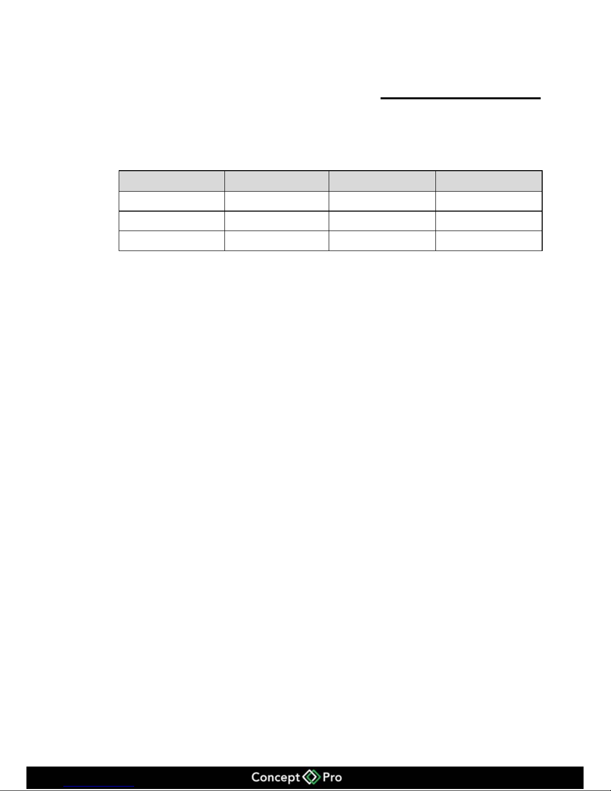
Table 4-1 Estimated video storage time
HDD capacity
Video stream
Cameras
Days recorded
2x4TB
D1 1.5Mbps
8
60
2x4TB
720p 3Mbps
8
30
2x4TB
1080p 4.5Mbps
8
21
Page 11
7
4.2 Front panel description
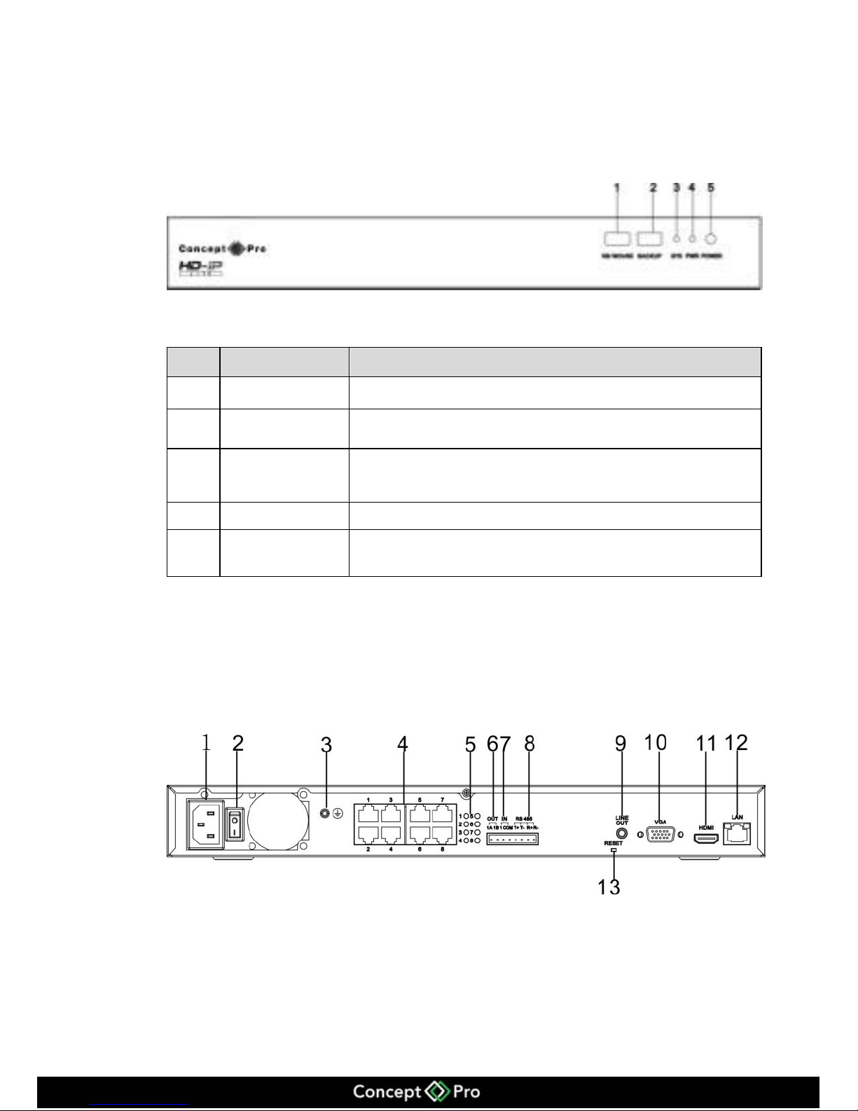
Figure 4-1 shows the front panel of the VHDIPL. Table 4-1 shows the description of
the front panel.
Figure 4-1 Front panel
Table 4-2 Front panel description
No.
Name
Description
1
USB Interface
For connecting external mouse and keyboard.
2
USB Interface
For connecting USB memory stick.
3
System LED
The system LED is a solid red.
4
Power LED
VHDIPL is turned on and the power LED is a solid red.
5
Power button
Power ON/OFF key – need to input password when
shutting down.
4.3 Rear panel description
Figure 4-2 shows the rear panel of the VHDIPL. Table 4-2 shows the description of the
rear panel.
Figure 4-2 Rear panel
Page 12
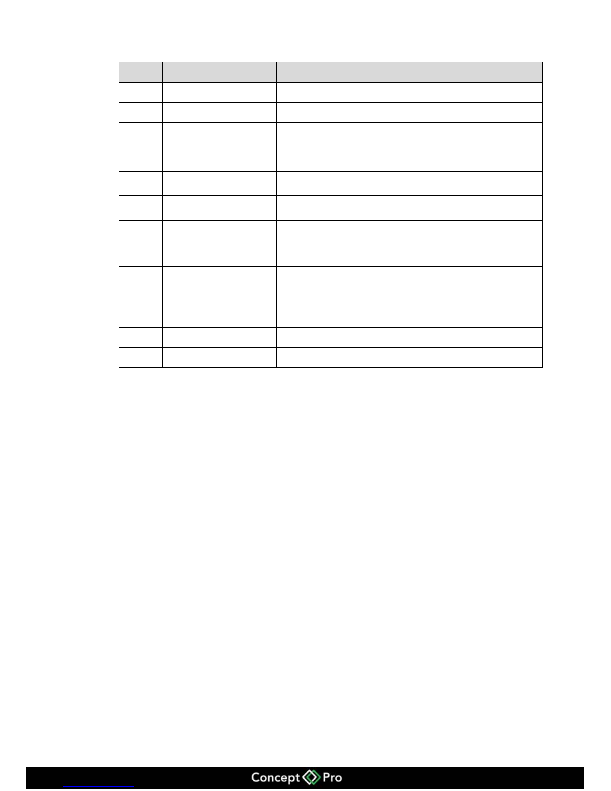
8
Table 4-2 Real panel description
No.
Name
Description
1
Power
AC110/220V power in.
2
Power button
Power ON/OFF.
3
Ground connector
Safety ground connector.
4
POE Ethernet ports
8ch POE Ethernet ports for IP cameras
5
Ethernet LEDs
POE Ethernet port LEDs.
6
Alarm out
1ch Alarm Out, for future development.
7
Alarm In
1ch Alarm In, for future development.
8
RS485
1ch RS485 for future development.
9
Audio Output
3.5mm linear audio output.
10
VGA
VGA output.
11
HDMI
HDMI output.
12
LAN port
RJ45 10/100Mbps.
13
Reset
Press for 5 seconds to reset.
Page 13
9
4.4 First boot
Make sure that the VHDIPL has the correct amount of power.
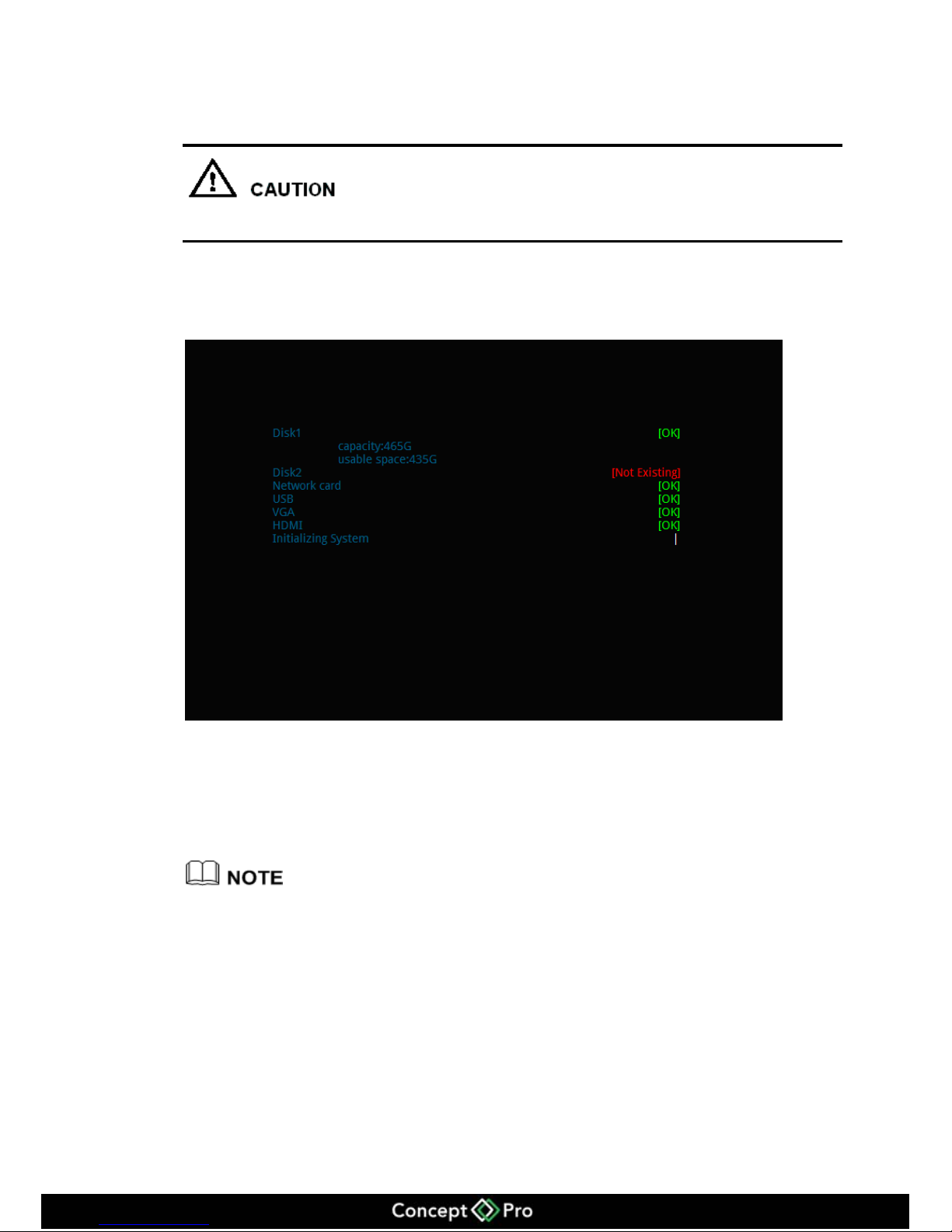
Once the VHDIPL starts and after the self test, (which takes about 2 minutes) the
results are displayed on the screen shown in figure 4-3.
Figure 4-3 Device power on
If an error occurs while the VHDIPL is in self-test, this mode will stay in the lower
right of the screen, you can choose to continue or shutdown. If you choose to continue,
the device will continue to start, until the device login screen is shown.
If the HDD fails testing, the reasons may include the following:
Unformatted or new hard disk, go to quick configure to format the hard disk drive.
Formatted hard disk drive, the VHDIPL supported file systems do not match.
Hard disk drive is damaged.
Page 14
10
4.5 Shutdown
Shutdown process, the system prompts are off, do not cut off the power.
Do not remove the power cables while the VHDIPL is still on.
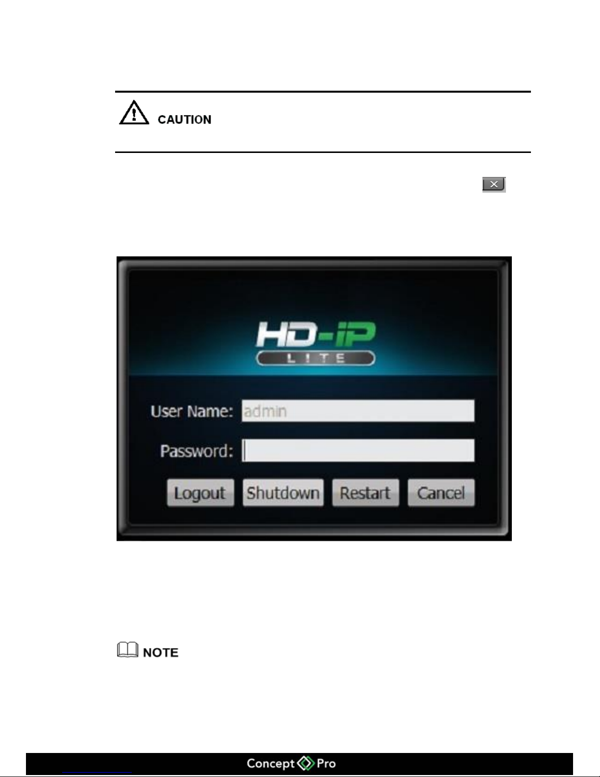
If the device is logged into the main interface, you can click the top right
button and this will bring up the shutdown interface, shown in figure 4-4.
Figure 4-4 Shutdown interface
4.6 Display resolution adjustment
The VHDIPL will support resolutions with VGA 1024 x 768, VGA 1280 x 1024, VGA
1600 x 1200, HDMI 720P, HDMI 1080P, you can select the correct resolution
according your monitor.
When using VGA we advise to set it to VGA 1024 x 768 or VGA 1280 x 1024. When using
HDMI input we advise to use HDMI 1080P.
Page 15
11
Adjustment Steps:
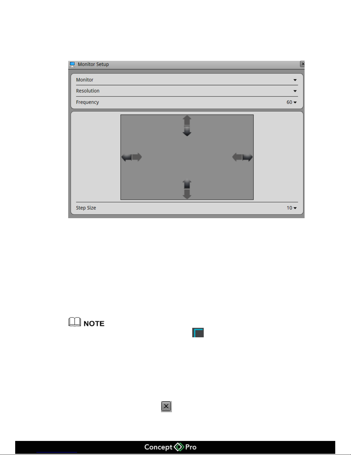
Step 1 Click change on login interface and find the adjustment interface shown in figure 4-5.
Figure 4-5 Monitor Adjustment Setup
Step 2 Choose the type of resolution in the resolution drop-down box.
The VHDIPL will automatically switch to the selected resolution and show the
following dialog options Yes or Cancel.
If no selection is made within 10 seconds, the display will return to the previous
resolution.
If you select Yes then it will switch to the selected resolution.
If you select cancel the display will not save the configuration and go back to the
previous resolution.
Step 3 Adjust display.
If the monitor does not show the full screen ( does not appear at the corners) screen
adjustment is needed.
1. Click Adjustment button at lower right corner.
2. In the step of the drop-down box to choose the adjustment step.
Step size: The moving distance when adjusting screen each time, the greater
number the more moving distance, you can select larger step sizes to adjust quicker,
and then select the smaller step to adjust more accurately.
3. Use UP, DOWN, LEFT, RIGHT button to adjust the screen.
Step 4 Click the configuration interface to close.
Page 16
12
Exit display interface
Back to Login interface
4.7 Adding Network Cameras
The VHDIPL-8 allows you to connect a maximum of 8 networked cameras. The total
recording bit rate is 36 Mbps and the live bit rate is 36Mbps.
The VHDIPL will support a maximum of 8 cameras at 1080p resolution with
average bit rate of 4.5 Mbps. If the total bit rate is more than 36 Mbps it may cause
the VHDIPL to lose video.
For detailed specifications please refer to chapter 2 Specifications.
Add Network camera
The cameras will be added automatically when they are connected to the POE ports in
the back of the unit.
Page 17
13
4.8 Login
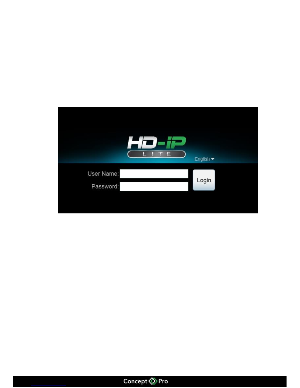
Login to the VHDIPL using the following steps:
Step 1 In the login screen shown in figure 4-6, enter a user name (default is admin), password
(default is admin).
Figure 4-6 Login screen
Step 2 Click Login and enter the main interface.
Page 18
14
5 Quick configuration
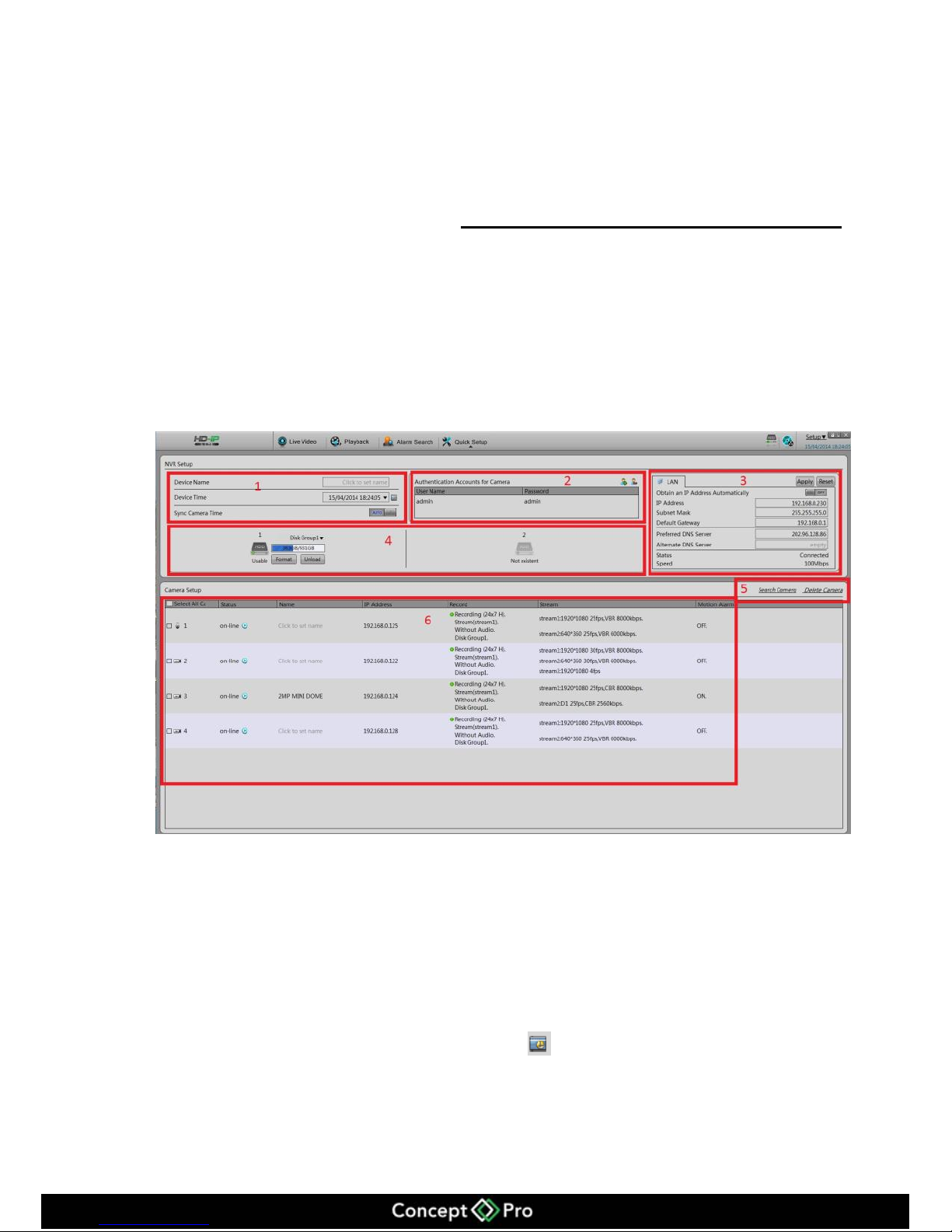
To quickly configure, use the quick configuration interface of the VHDIPL. It provides:
The network configuration, disk management, date and time configuration, search
network cameras, video configuration, camera network configuration stream
configuration and motion detection configuration. Enter the quick configuration
interface, as shown in figure 5-1.
Figure 5-1 Quick Configuration Interface
The quick configuration interface description.
Area 1: VHDIPL basic information and time synchronization functions.
Set the name, date and time.
Synchronize the time of the network cameras. You can select manual mode or
automatic mode.
When the manual mode is selected, click button for time synchronization.
When synchronize mode is selected, time will synchronize automatically by the
VHDIPL, this means all cameras will have internal times to match the VHDIPL
time.
Page 19
15
Area 2:Managing camera certification accounts.
The certification accounts used to log on to the network cameras. Only certified
network cameras can be added to VHDIPL system.
System cameras will have a default user account: admin and default password:
admin. Click to add a network camera certification account.
Click to select account to be deleted from the list.
Area 3:VHDIPL-8 network configuration.
VHDIPL factory default IP address: 192.168.0.120
The basic network configuration can configure the IP address, subnet mask, default
gateway, DNS address and other parameters. Real-time display of the network
connection status and speed.
Area 4:Hard disk management.
Formatting the hard disk will cause video loss, please use this feature with caution.
Always use the software function when removing hard drives and ensure that the
power is off.
Hard disk management:
To format the hard disk, click the format button, a pop-up prompts, click format. A
3TB HDD takes about 10 minutes to format.
Load or unload HDD. Do not take out the hard disk unless you have clicked on
unload first.
To modify hard disk group, add disk 1 to disk group 1 and disk 2 to disk group 2,
or add disk 1 and disk 2 to disk group 1, there are up to 2 disk groups in total as
there are up to 2 HDDs.
To view the status of the disk it will say one of the following; normal, abnormal,
unformatted drive or does not exist.
View the disk space and the total space.
Page 20
16
Area 5:Search cameras and delete cameras.
The VHDIPL-8 will automatically add the 8 cameras once they are connected to the
POE ports.
To remove the camera in the camera list, click the check box , select the
camera and then click delete to remove, shown in figure 5-1.
Area 6:Configuring the network cameras.
To view the status of the network camera, set the name of the network cameras, IP
address, video strategy, stream parameters, and motion detection parameters.
View the status of network cameras: online, not online, account errors.
1. To preview real time video click .
2. Modify the name of the network camera.
Enter the desired name of the device.
Modify the IP address of the network camera.
1. Click the camera to modify the IP address, network cameras IP Settings, a dialog
box pops up.
2. Set the network camera IP specific operation methods and procedures, see chapter
9.1.4.
Set the device stream.
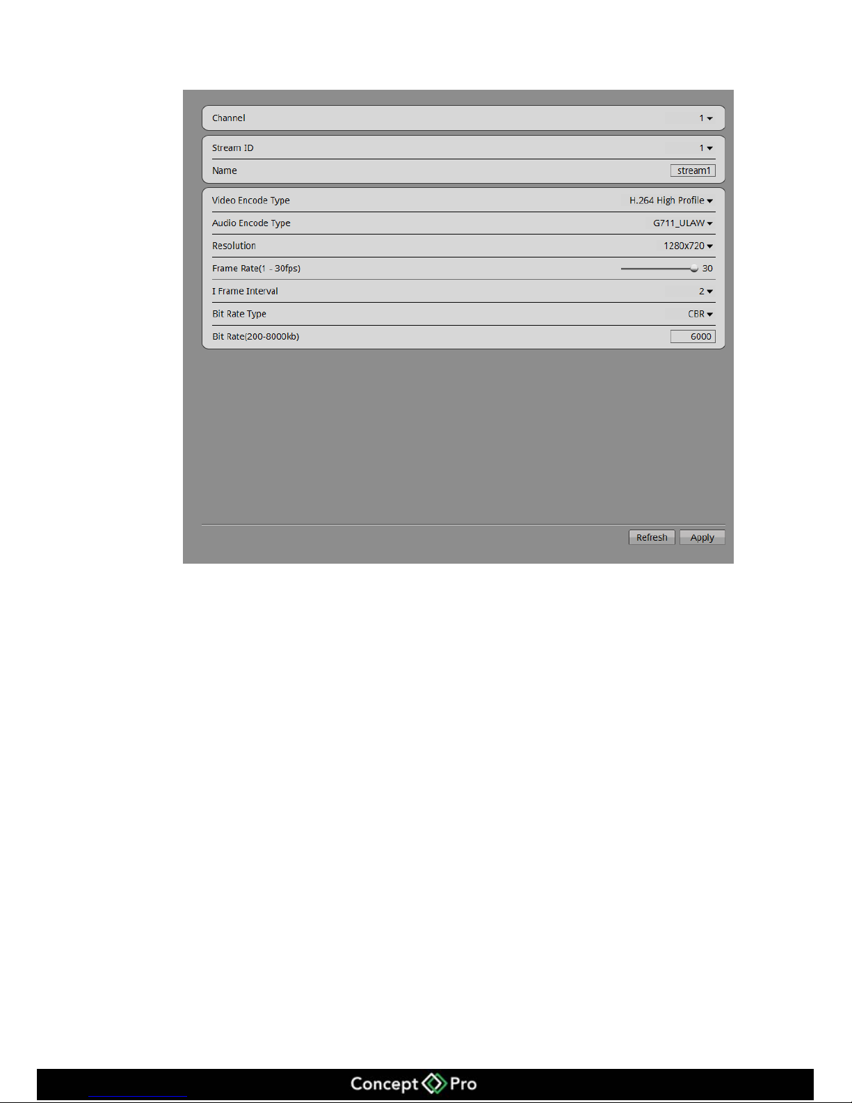
1. Click stream information to pop-up the stream configuration dialog box shown in
figure 5-2.
Page 21
17
Figure 5-2 Stream Quick Configurations
2. Click the Apply button to set the current parameters to the devices.
Set to detect motion detection alarm, shown in figure 5-1.
1. Click motion detection, and the motion detection alarm dialog pops up.
2. If you want to turn on the motion detection alarm, you must set the arming time
and detection area.
Page 22
18
6 Live video
To input the username (default is admin) and password (default is admin), click login.
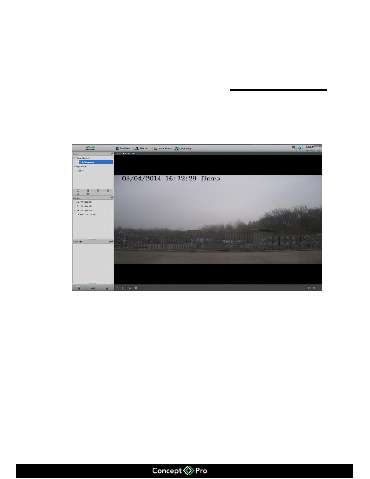
Enter the live video interface, shown in figure 6-1.
Figure 6-1 Live Video Interface
In the live video interface, you can select the cameras from the left list to view live
video. You are also able to do the below operations:
3. Live video
4. Alarm log tracking
5. Monitor the recording status
6. PTZ Control
7. Audio
8. Full screen automatically
9. Video mark
10. Sensor configuration
Decoding ability
This system decoding ability is 8 channels at 1080p.
Page 23
19
Intelligent adaptive mechanism of stream frame rates
This system provides the intelligent adaptive mechanism of stream frame rates.
When you are selecting the camera to watch in live video, the system will select the
suitable stream according to system’s own decoding ability and live video windows. It
will always ensure the system works with the best performance.
To change the streams manually, right click the screen to access the menu, then you
will be able to see all the available streams in the current camera. After the streams are
switched at the bottom line of the live video window the stream information will
appear.
Live video interface introduction as figure 6-1 (above).
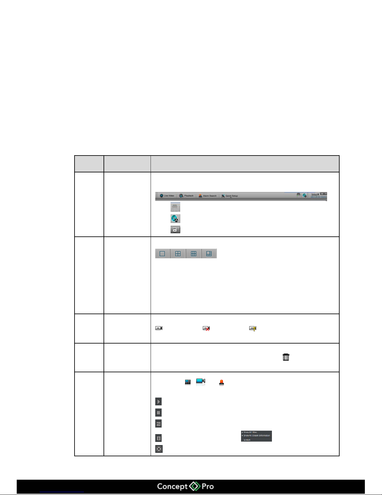
Table 6-1 Live video interface introduction
Items Na me Content
1 Top menu
Click Live Video, Playback, Alarm Search and Quick Setup to enter the
interface.
Click icon to check the HDD information.
Click icon to enter the recording backup interface.
Click icon to lock the interface.
2 Channel Layout Select which display layout you would like from the available selection.
After selecting the layout mode, move the individual camera from the left
list to the position on the layout screen you want it to appear in. Click the
save button to save the layout.
There are two options “Shared layout” and “My layout”, this also supports
“Cycle” mode, we can configure this in Setup > VHDIPL Setup > Live
Video Setup > Layouts.
3 Camera List
The camera list shows every camera that has been assigned to the VHDIPL.
means normal, means offline, means unverified (username or
password is not correct).
4
Alarm
information
This area displays the alarm information including motion detection and I/O
alarm. This will only display the last 20 alarms. Click to clear the
information.
5 Bottom menu
By clicking , and icons, the layout list, alarm list and alarm
information will be hidden or viewed.
:Play live video button.
:Close live video button.
:Click to select the PTZ control menu.
:Click to display the following.
: Selects Full Screen Video Playback
Page 24
20
Items
Name
Content
: Automatic Full Screen control
6
Live video
Right mouse click on the live display will allow the changing of some
display information. Start the audio, bookmark the current video footage for
ease of finding later, change the video stream and access the sensor
configuration set up menu of the camera being viewed.
: Mark/Tag, press this button during live video and the recording will be
highlighted in “yellow” and make it easier to find the footage at a later date.
Return to full screen automatically
Click to enable the return to full screen function, and set the time delay. When
this function is enabled, it will go to the full screen mode immediately. When it is in
full screen mode, move the mouse to the bottom line it will activate the tool bar, click
the icon to can exit the full screen mode. Click to manually return to the
full screen.
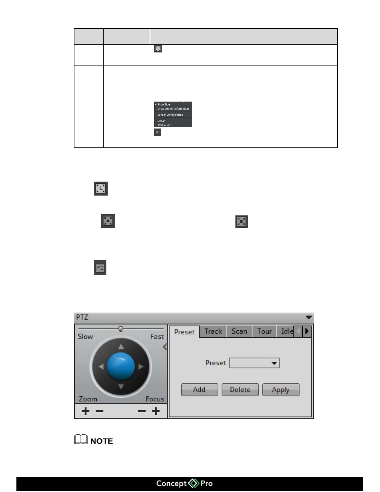
PTZ control
Click button to call the PTZ control menu, as shown in figure 6-2. In this
interface adjust pan, zoom, preset, trajectory, scanning, infrared light, north, timer
settings etc.
Figure 6-2 PTZ Control Menu
PTZ Control menu only can be operated with IPS Dome and Ext PTZ platform.
Page 25
21
Click button to close the PTZ configuration menu.
Click button to exit the PTZ control menu.
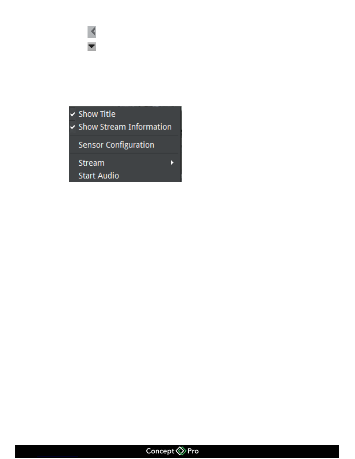
Live video fast operation
Right click mouse button to activate figure 6-3 interface, call the menu to: Show Title,
Show Stream Information, Start Audio, Stream, Sensor Configuration etc.
Figure 6-3 Live video monitor menu
Page 26
22
7 Playback
7.1 Recording playback
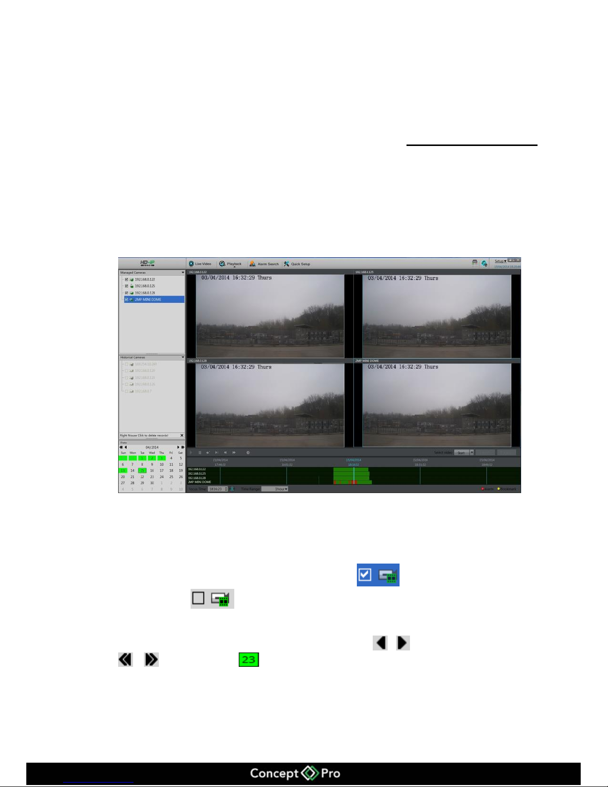
Recording playback will playback the video which is recorded to the local HDD,
shown in figure 7-1.
Figure 7-1 Local playback
Playback operations steps.
Step 1 Choose the camera to playback.
Click one from the list on the left hand side, icon means this camera has
been selected, means camera has not been selected.
Step 2 Date selection.
You can select the date period on the calendar. Click , to switch month, click
、 to switch year. Means selected date. When it is marked green it means
this day has recorded footage, otherwise there is no recording on that day.
Page 27
23
Step 3 Recording shown.
After selecting the device and date, at the bottom area of the live video, it will display
the recording status. The scale on the time axis shows the recording time period, blue
means the current playback video time. The playback video will be displayed above the
time axis, blue means retain video, red means alarm video, yellow means label video,
green means normal video.
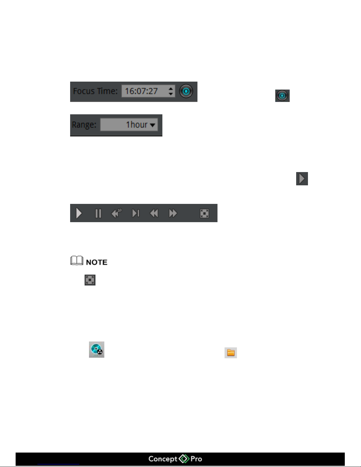
: Input the time, then click , the
playback video will jump to the pointed time.
: After the time zone, you can select the time interval:
15 minutes, 30 minutes, 1 hour, 4 hours, 8 hours, 12 hours, 1 day.
When 1 hour is selected, then the time period between the two blue lines is 1 hour.
Step 4 Playing recorded footage
After selecting the camera and date, to start playing the recorded footage, click
Figure 7-2 Control Tool Bar
From left to right are: play, pause, rewind 10 seconds, single frame playing, rewind,
fast forward and full screen button.
During the playback, you can try to move the mouse to control the playback processes, click
to switch to the full screen mode.
7.2 Recording backup
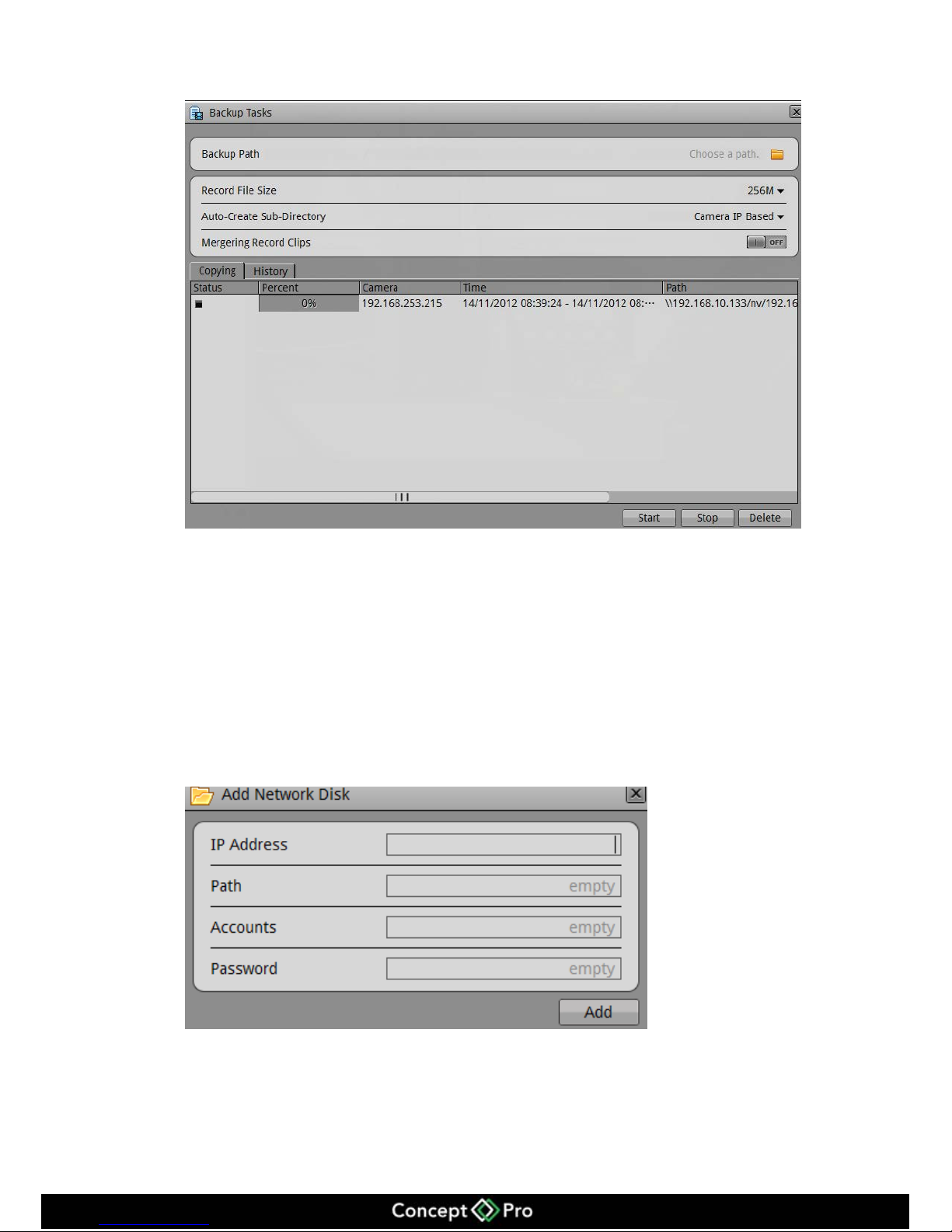
Step 1 Configure the backup path.
Click button to call the backup interface, click button to call the backup
path configuration interface shown in figure 7-3.
Page 28
24
Figure 7-3 Backup Path Browser
In the backup path, it will display the current backup path, if it is blank, and then select
one option. In the below list it shows the available storage paths. The VHDIPL will
support two kinds of the storage: Network Attached Storage (NAS) and USB storage
device (USB memory stick or Removable HDD).
Network Attached Storage
4. Double click the Add Network Disk, or right click the menu to call the Add
Network Disk interface, shown in figure 7-4.
Figure 7-4 Add Network Disk
5. Input the IP address, path, account and password, click Add.
6. Check the network disc status. The status list: OK, connect fail, unavailable. When
status is OK it means the network disc can be used for backup.
Page 29
25
7. Double click the network disc path list, select the backup path, click ok button save
and exit.
USB Storage device
1. Insert USB memory stick or removable HDD to the USB interface.
2. The VHDIPL will detect the USB storage device automatically, after detection, it
will show USB storage device.
3. Right click menu to select unmount or formatting options on the USB memory
stick.
4. Double click the USB storage device path list, select the backup path, click OK and
exit.
Step 2 Configure the backup file options.
8. You can define the maximum size of an individual file.
9. Create the sub directories, it can be created by the directories based on the network
cameras IP address or ID.
10. To combine the recorded video clips ensure the "Merging Recorded Clips" function
is ON.
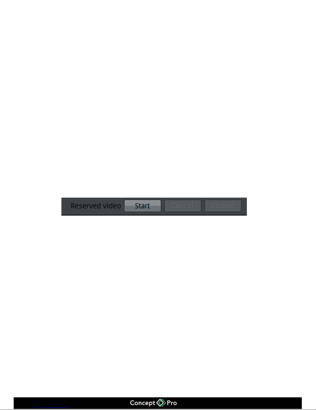
Step 3 Select backup recording
Method one: Select the recording and backup during the playback process. Recording
backup control bar as shown in figure 7-5:
Figure 7-5 Recording Backup Control Bar
1. Click the Start button to start selecting the recording segment.
2. Select the recorded footage, press the left mouse button to move to the left or right
side to highlight the footage you want to backup.
3. Click Stop button to stop the selection, (You can also click the cancel button to
cancel the current selected video segment).
Click backup to start the backup.
Method two: In alarm searching, when you are playing the playback alarm triggered
footage, you can click backup to make the backup files.
Page 30
26
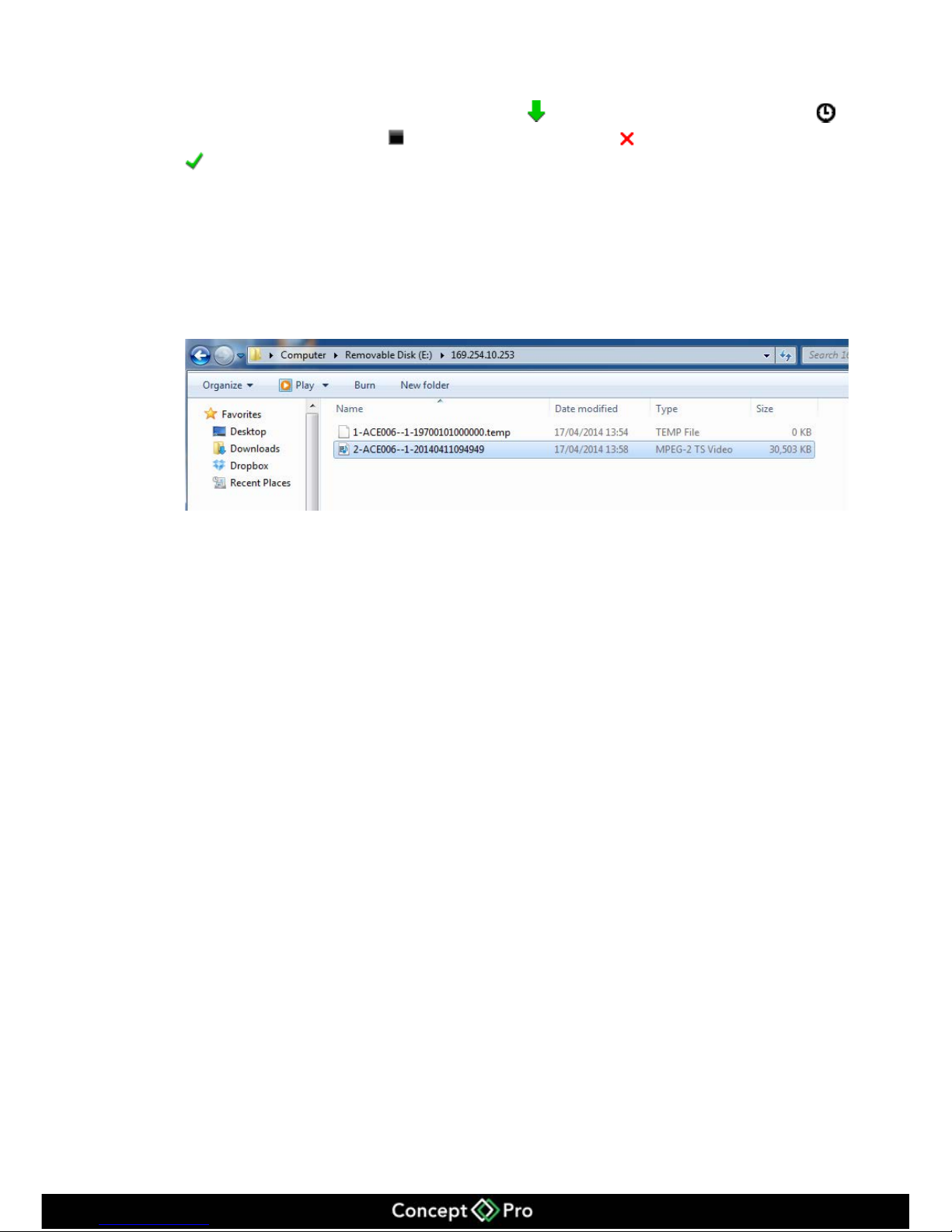
Step 4 View backup file progress
Check the backup status in backup interface, indicates backup is in processing,
indicates wait for backup, indicates backup stopped, indicates backup failed,
means backup finished.
Step 5 On a computer
Enter the backup directory folder, enables the user to check all the backup files.
Enter the backup path folder to check the backup files, shown in figure 7-6.
Figure 7-6 File Search
Page 31
27
8 Alarm searching
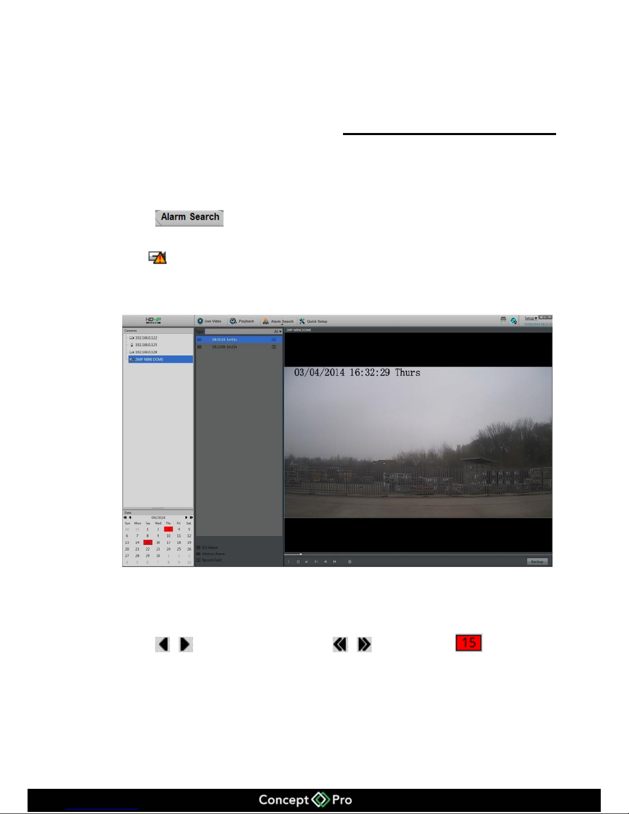
Alarm searching Interface
Operation steps
Step 1 Click to enter the alarm management interface shown in figure 8-1.
Step 2 Select the camera which you want to search the alarm information from the list on the
left. Indicates this camera has alarm information.
Step 3 Select the alarm type at the Type drop-down menu.
Figure 8-1 Alarm Searching Interface.
Step 4 Date selections.
Choose the date period which you want to search in the calendar area.
Click , to switch the month, click , to switch year, Means the
date which has been selected. If red then, that day has alarm recordings.
Page 32

28
Step 5 Recording shown.
When you have selected the time and date you can play the alarm recording.
Step 6 Alarm triggers playback.
Select the alarm trigger recording files, click button to start playing.
Step 7 Alarm recording backup
Select the recorded files and click backup button to create backup files.
Page 33
29
9 Setup
Setup includes the VHDIPL setup and the camera setup.
9.1 VHDIPL setup
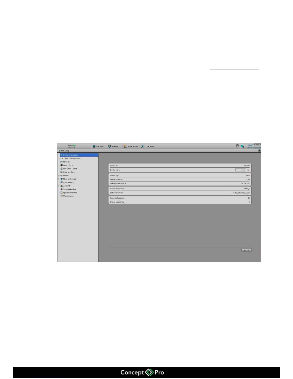
Click NVR setup in upper right to show the VHDIPL configure interface shown in
figure 9-1.
Figure 9-1 NVR setup
9.1.1 Device information
When in the VHDIPL setup interface, we can see the system information shown in
Figure 9-1.
Device information includes:
Device ID
Device Name
Manufacturer ID
Manufacturer Name
Page 34
30
Hardware Version
Software Version
Channel Quantity
Disk Quantity
Only the device name can be edited, other parameters can’t be edited.
9.1.2 Camera Management
You can see and delete cameras via Camera Management.
Select NVR setup > Camera Management
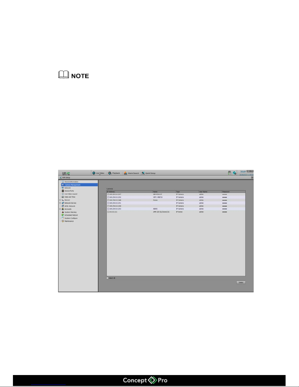
Enter the camera management interface, shown in Figure 9-2; it will list all the cameras
which are connected with the VHDIPL, and some basic information.
Figure 9-2 Camera Management Interface
Page 35
31
9.1.3 System Warning
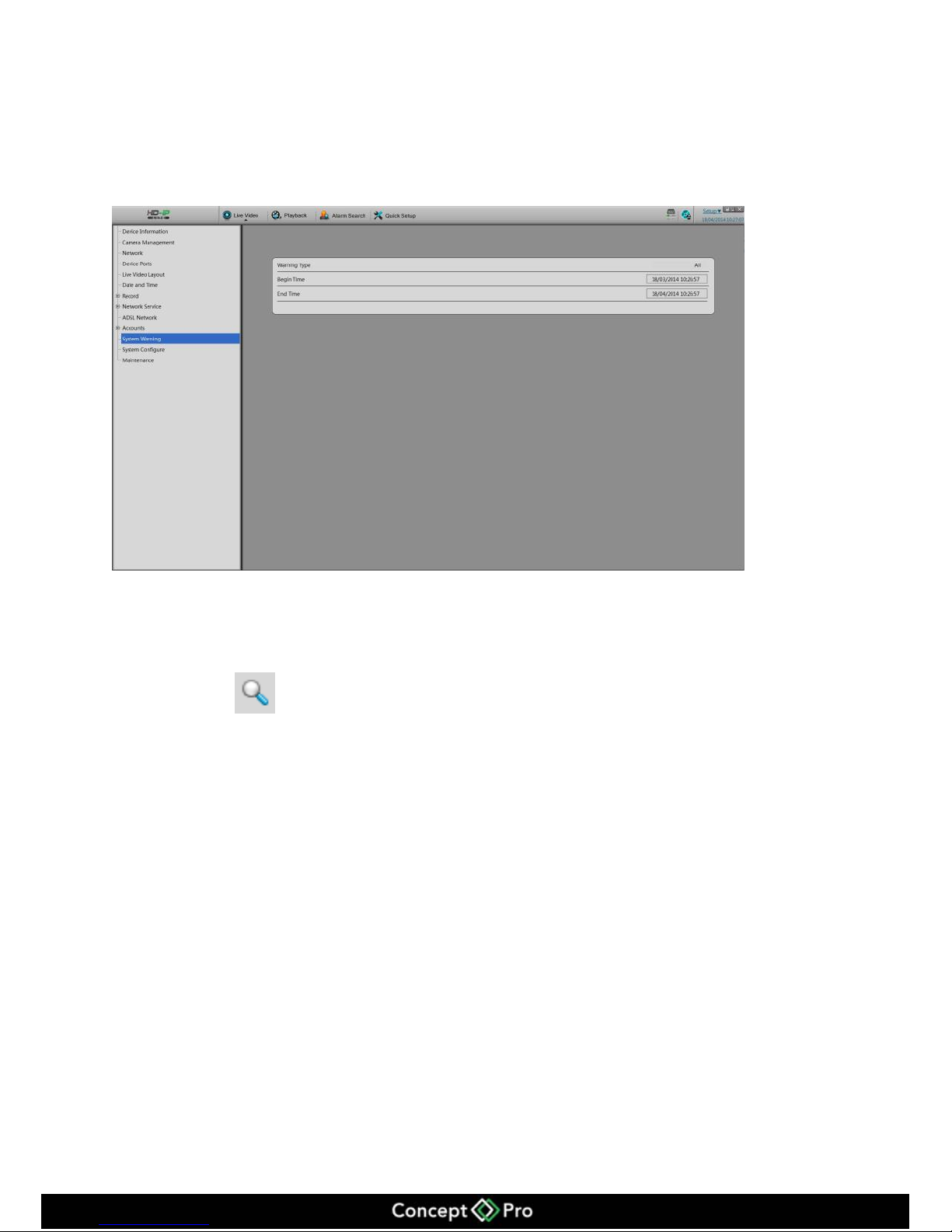
Select Setup > System warning
Enter the system warning shown in figure 9-3.
Figure 9-3 System Warning Information.
Warning information searching steps.
Step 1 Select the warning type (Disk Alarm, Record Alarm, All).
Step 2 Input search begin and end time.
Step 3 Click , then the results will be displayed.
9.1.4 Network
You can check the camera’s DHCP IP address, configure IP address, subnet mask,
gateway address, first DNS and backup DNS.
Operates steps
Step 1 Choose configure > system configure > network
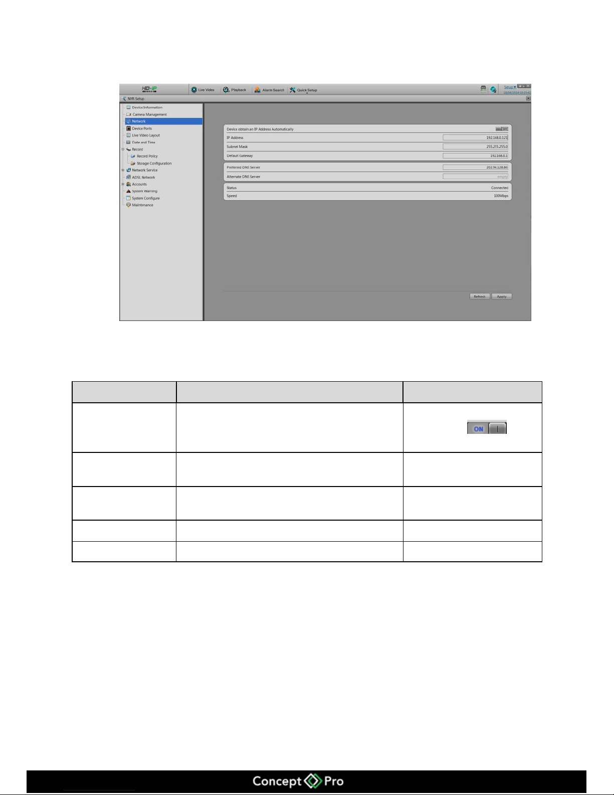
Enter the network configuration interface shown in figure 9-4.
Page 36
32
Figure 9-4 Network Interface
Step 2 Configure the network parameters, shown in table 9-1.
Table 9-1 Network parameters
Items
Introduction
How to configure
Get IP address
automatically
It will get the IP address from DHCP server
automatically.
Switch DHCP to on by
this button .
IP Address
It can configure the NVR’s IP address.
Default IP is
192.168.0.120
Subnet mask
Configure the subnet mask
Default address is
255.255.255.0
Gateway
Configure the Gateway address
Default is 192.168.0.1
DNS
Configure the DNS server address
Default is 192.168.0.1
Step 3
11. Click Apply, then a message saying "Applying succeeded" pops up then click ok.
12. If another window pop ups, then please confirm the parameters are all correct and
configure again.
Page 37
33
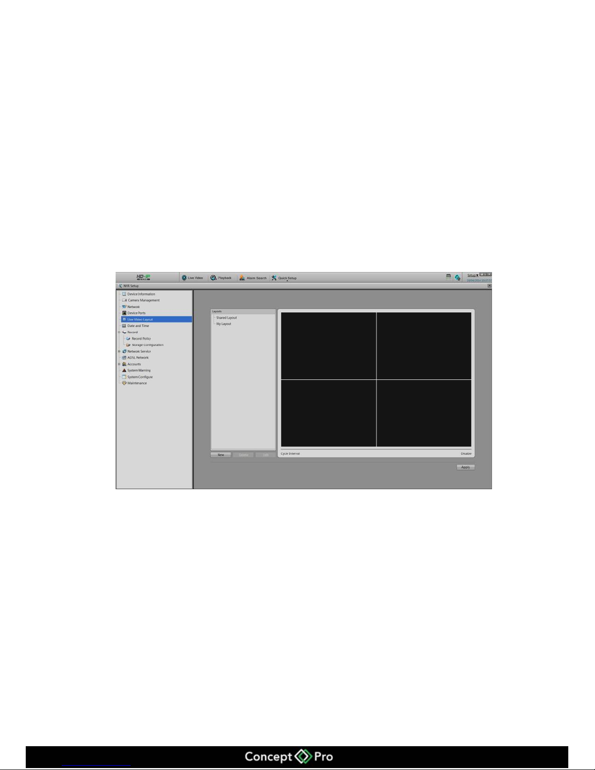
9.1.5 Live video layout
You can configure the live video layout in order to call the live video quickly.
Live video layout can do the below operations:
Create a new layout
View a current layout
Edit a current layout
Create New layout
The steps to create new layout are shown below:
Step 1 NVR Setup > Live Video Layout
Enter the live video layout shown in figure 9-5.
Figure 9-5 Live Video Layout
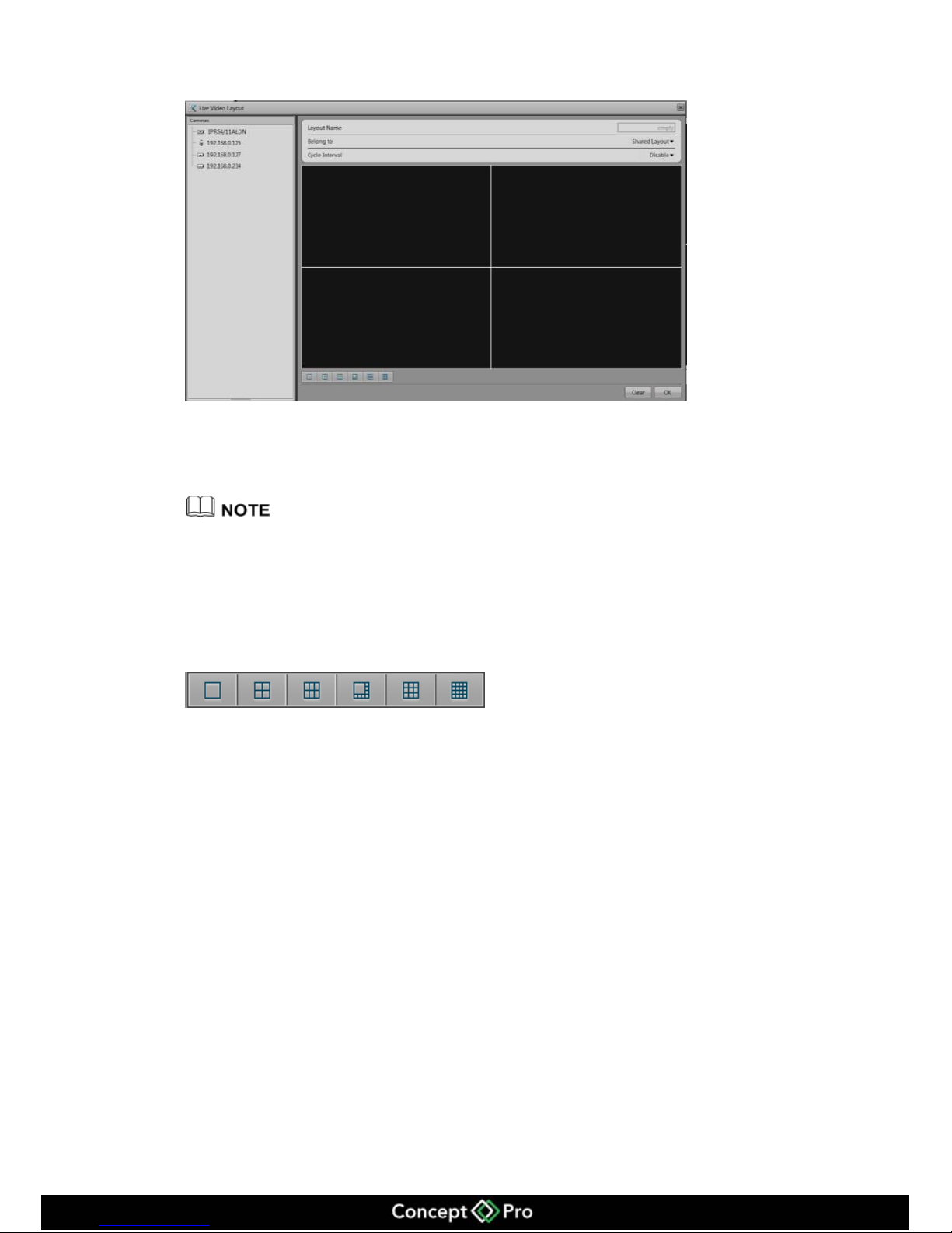
Step 2 Click New to call the new layout shown in figure 9-6.
Page 38
34
Figure 9-6 New layout
Step 3 Input the New layout name
Step 4 Configure the New layout position, you can select the Shared layout or my layout.
Shared layout means the layout for all the users.
My layout means the layout for current login user only.
Shared layout can only be created by authorized users.
Step 5 Configure to enable the wheel guard or not. Wheel guard time interval could be set as
5s, 10s, 30s, and 60s.
Step 6 Choose the screen split settings.
From left to right are single frame, 4 frames,
6 frames, 1+5 frames 9 frames and 16 frames. You can choose one of them.
Step 7 Left click the mouse to select the camera from the list and move to the live video
layout.
Step 8 Click Apply to finish and save the configuration. If a window pops up you may not
have not entered a new layout name as this cannot be left blank. Please input the layout
name.
Page 39
35
9.1.6 Recording
You can configure the Recording by Schedule, Alarm Recording, Recording Quality,
and Recording Policy.
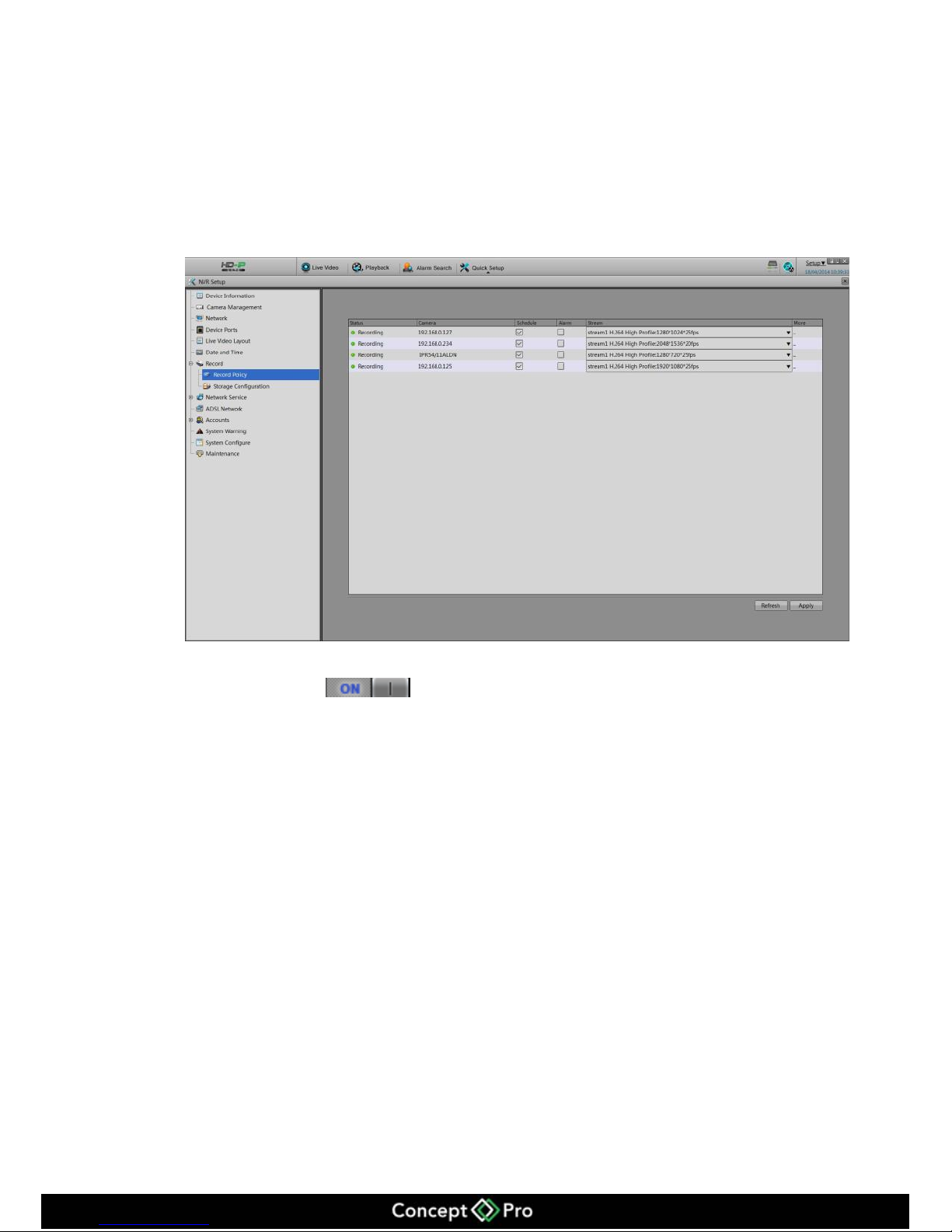
Step 1 Choose Setup > Record > Record Policy.
Enter the Record Policy shown in figure 9-7.
Figure 9-7 Record Policy
Step 2 Enable the record (Enabled as Default)
Step 3 Please select √ on the cameras which you want to record, and also select the
corresponding stream parameters.
Step 4 Click more
The record policy configuration interface will pop up, shown in figure 9-7.
Page 40
36
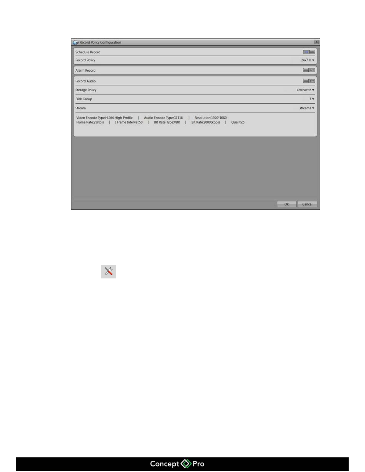
Figure 9-7 Record Policy Configuration Interface.
Step 5 Configure Record Policy
When configuring the record policy, there are two policies, 24 x 7 or Schedule.
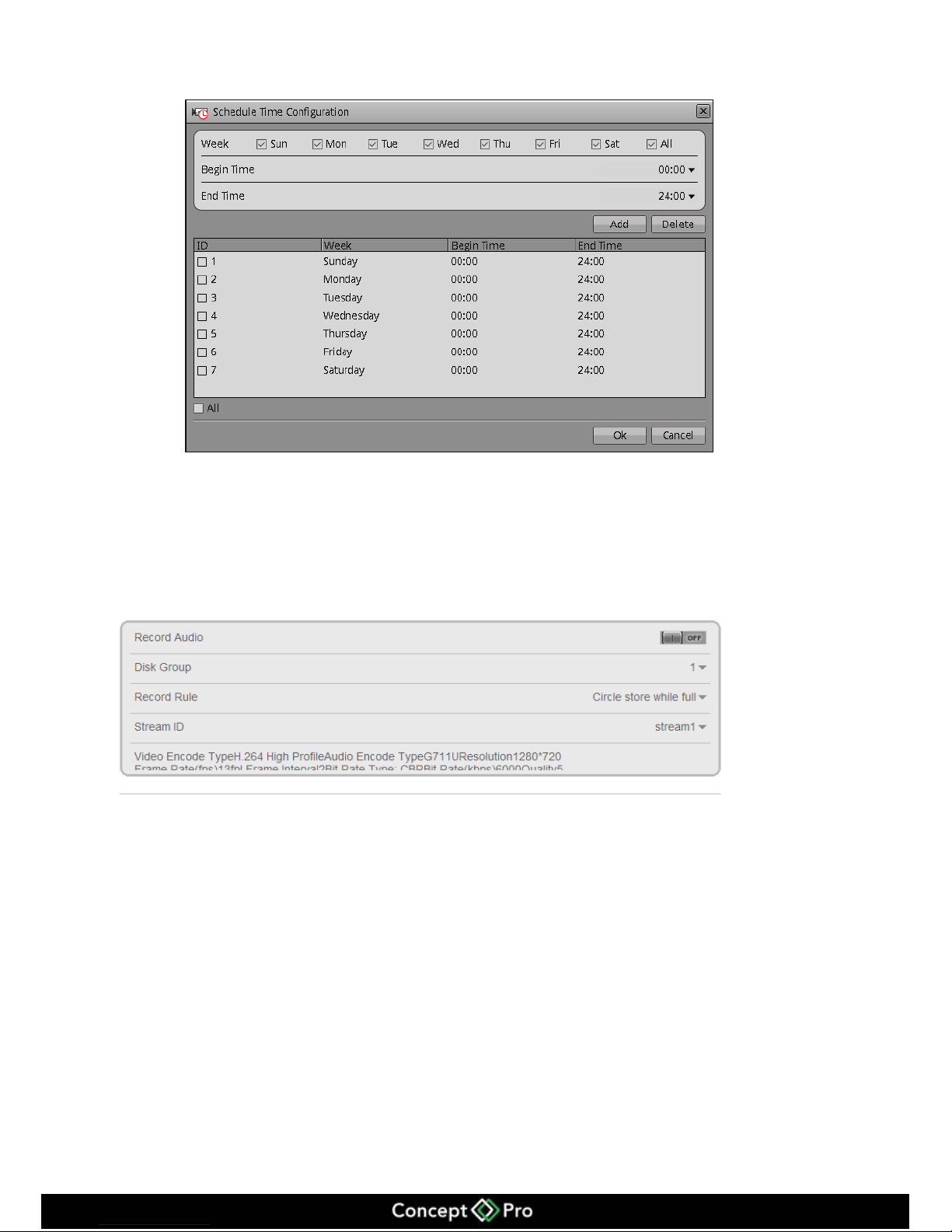
If you select record by schedule, you need to configure the schedule plan. Follow the
steps below.
1. Click to enter the schedule record configuration interface.
2. Configure the schedule for recording shown as figure 9-8.
3. Click Apply to save.
Page 41
37
Figure 9-8 Schedule record configuration
Step 6 To enable the alarm record
If you do not want to enable the alarm record, then just set the button to OFF.
If you want to enable the alarm record, then set the button to ON.
Step 7 To enable the audio
Slide the bar to on.
Step 8 To configure the storage policy, select either:
When HDD is full, overwrite.
Retention period.
Step 9 Configure the HDD disk group.
There will be 2 HDD disk groups. You can set the recording to be recorded to the
different disk groups or you can set all HDDs to 1 disk group.
Step 10 Configure the record streams bit rates.
Step 11 Click Apply to save the configurations and exit the record policy interface.
Page 42
38
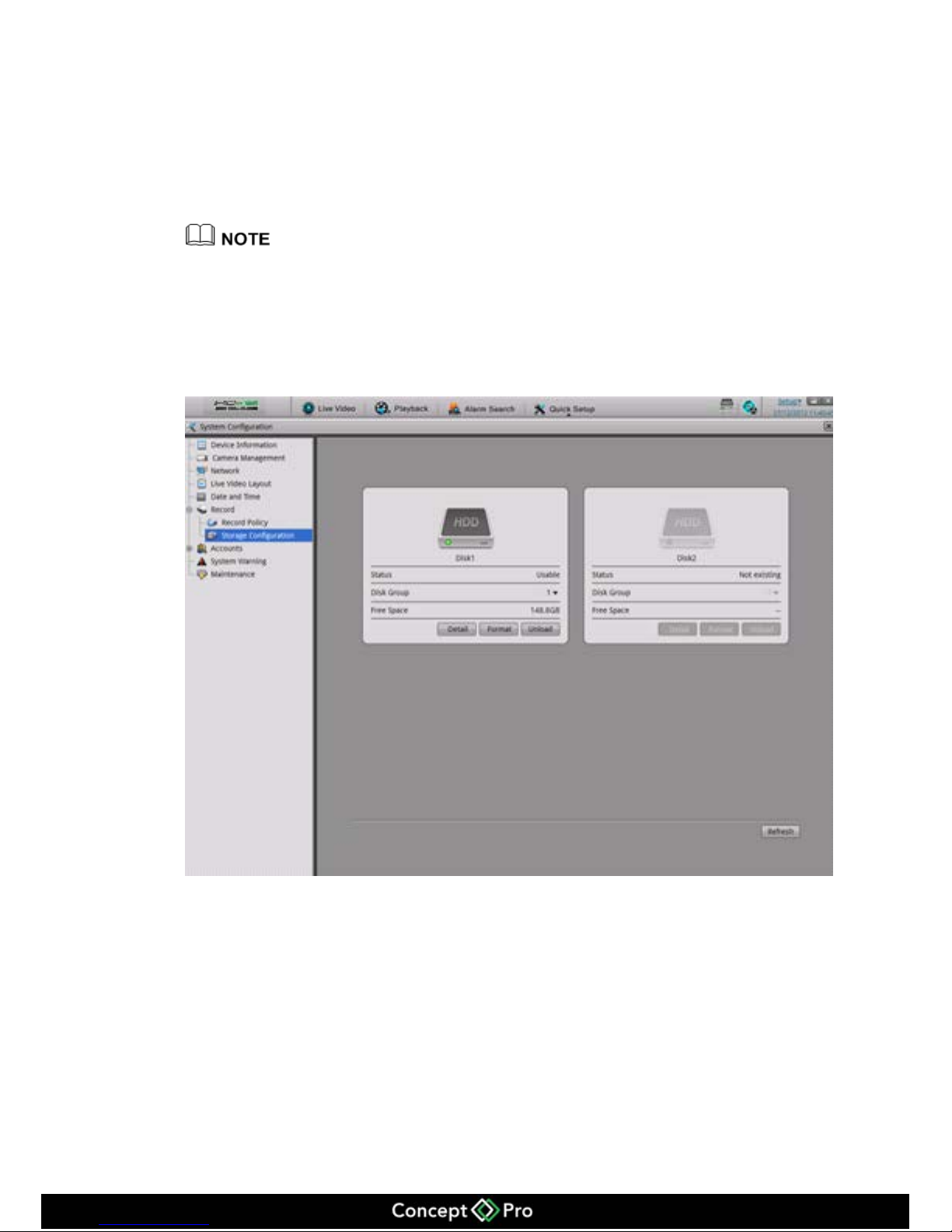
9.1.7 Storage policy
In storage policy interface, you can do the following operations:
Check the current HDD status.
Check the HDD information details include: HDD capacity and free space.
Unload and format operations.
When you first use the VHDIPL you will need to format the HDD otherwise recording will
not be written to the HDD.
Select System configuration > Record > Storage Configuration.
Enter the Storage Configuration, shown in figure 9-9.
Figure 9-9 Storage Configurations
9.1.8 Account Management
Privilege group setting
User’s basic privilege includes:
Live video
Playback
Backup
Alarm search
Page 43
39
System Management
Shutdown
Record service
Set shared layout
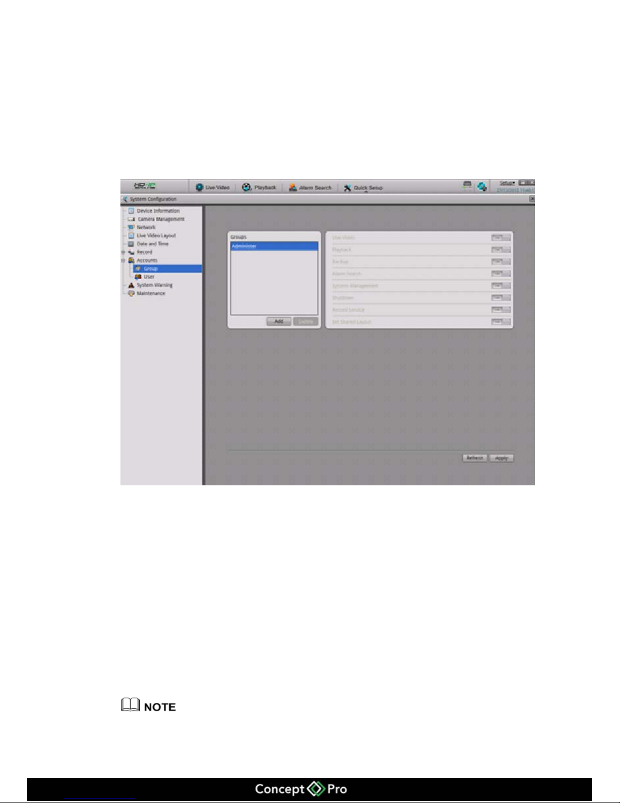
Step 1 Accounts > Group
Enter the Group configuration interface, shown in figure 9-10.
Figure 9-10 Group configuration interface
Step 2 Add and Delete Groups
Add privilege group.
1. Click Add to bring up the Add Group Interface.
2. Input Group Name.
3. Click OK. Once added, return to the original interface.
4. Select the groups which are added, and select the privileges which they can have.
5. Click Apply to finish.
Delete Privilege group.
1. Click Delete to call the Delete Privileges Group interface.
2. Click yes to return to the original interface.
3. Click Apply to finish the operation.
System default privilege group is Administrators, which cannot be deleted and modified.
Page 44
40
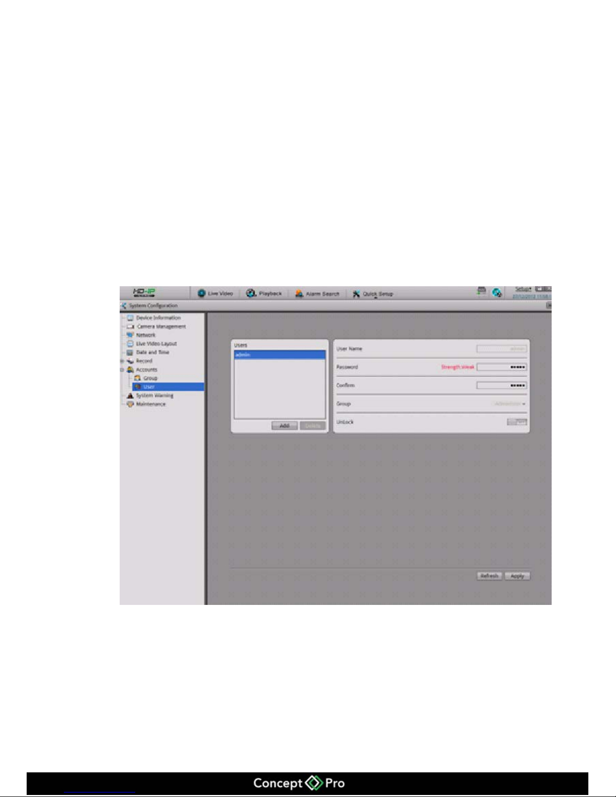
User setting
You can add and delete users. The users which have the privilege of system
configuration can unlock the system, it may be locked by inputting an incorrect
password more than 3 times.
Step 1 System configuration > Account > User
Enter the user interface shown in figure 9-11.
Step 2 Add and delete user.
Add user
1. Click add to call the add user interface.
2. Input the user name.
3. Click OK.
Finish adding the user, return to the previous interface.
Figure 9-11 User configurations
4. Configure the user password and privilege group.
5. Click Apply to finish the user adding configuration.
Delete user.
1. Click delete to call the delete user interface.
2. Click yes to return the previous interface.
3. Click Apply once finished.
Page 45
41
Unlock the locked user
When logged on to the system, if the user inputs the wrong password more than 3 times,
then the system will lock the user, but only the administrator can unlock the user.
9.1.9 Date and Time Configuration
You can set the Date and Time and the Date and Time format of VHDIPL.
Step 1 Setup > System Configuration > Date and Time,
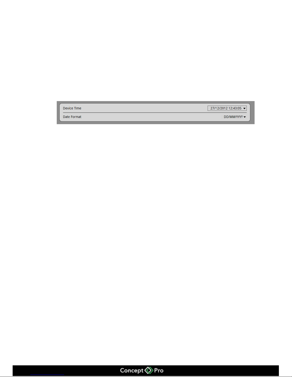
Enter the date and time shown in figure 9-12.
Figure 9-12 Date and Time configuration
Step 2 Input the correct time.
Step 3 Choose the date and time format which you want to use.
9.2 Camera management
In the camera management interface you can configure the parameters of the cameras
which have been added to the VHDIPL.
It is the same to configure the device from the VHDIPL and from the WEB. Please see
the VIPC-MB720 or VIPC-MD720 User Manual.
Page 46
42
10 Web Browser Access for VHDIPL
VHDIPL Web Server, built-in flash technology supports IE, Chrome, Firefox, Safari
and other popular browsers. It can be quickly be configured through the Web. Live
preview, video playback, alarm retrieval, VHDIPL configuration, camera configuration
and other operations can be configured through a web browser.
10.1 Login
The VHDIPL default IP address is: 192.168.0.120. Input the IP address of the VHDIPL
into the address bar of the web browser to view the VHDIPL remotely.
Please make sure the network is correctly configured and connected.
The computer must have the flash player installed before main system can be used.
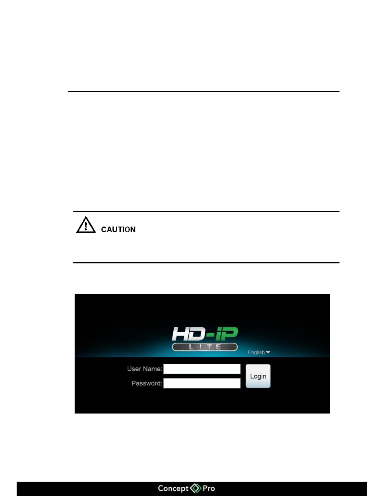
VHDIPL Web login screen shows in Figure 10-1.
Figure 10-1 VHDIPL Login interface
Enter a user name and password into the login screen to enter the main page
Default user name and passwords are both admin
Page 47
43
Administrator user ID: admin, administrator password: admin. User names and passwords
are case-sensitive. Please modify the password after the first login. After three failed
attempts of inputting the incorrect password the user will be locked, and will no longer be
able to continue to log in until the administrator can unlock the user.
10.2 Operation Read
10.2.1 Player
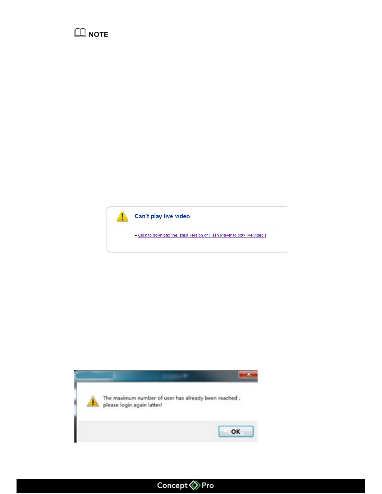
VHDIPL web video function needs Adobe Flash Player to support it. If you do not
install the Adobe Flash Player or if the player version is too low then it can’t play the
video shown in Figure 10-2.
Figure 10-2 Can’t play video interface
Please download and install the correct version of Adobe Flash Player.
10.2.2 Video capability
The VHDIPL can only support 4 users to access the web client and use the VHDIPL at
the same time. When the online users reach over 4, a dialogue will be shown as figure
10-3.
Figure 10-3 Number of users exceeded
Page 48
44
VHDIPL web will only support 8 channels live video and 1 channel playback for one
user login (maximum ability), with other users it will only support 1 channel Live
video and 1 channel playback (minimum ability).
The first login user will be the maximum ability user. Other users are the minimum
ability users, when the maximum ability user logs out then the next user login will be
the maximum ability user.
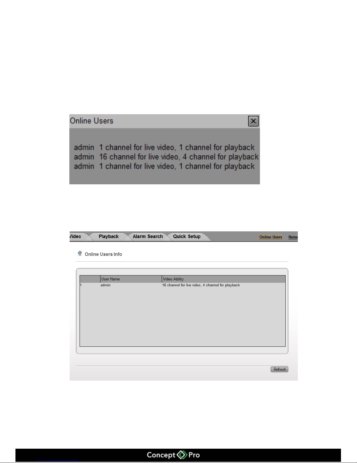
The VHDIPL will adjust the video ability according the user login, when user logs in
the bottom of the screen will show a message shown in figure 10-4.
Figure 10-4 User Video Ability Information Interface
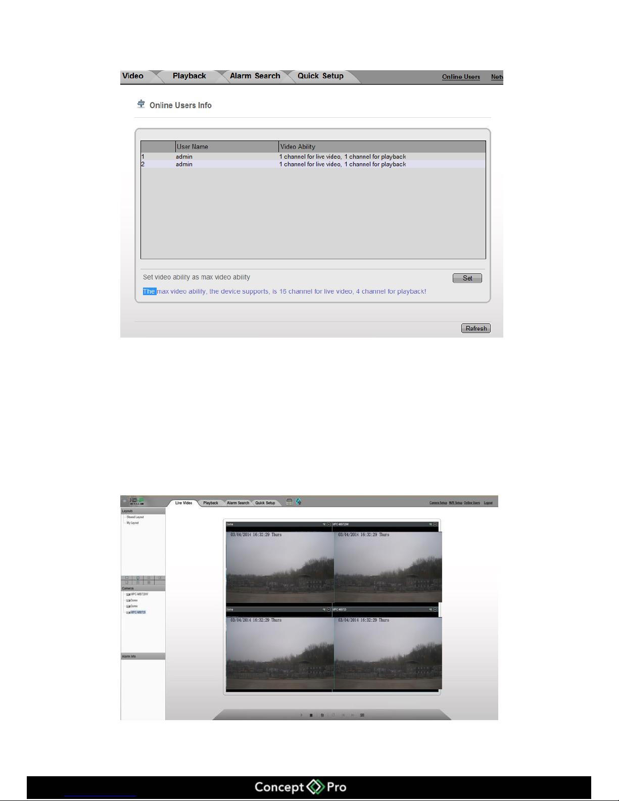
Click the online users on the web and it will enter the online users interface, from there
you can see all the online user’s video ability. Shown as figure 10-5.
Figure 10-5 Online Users
Click Refresh to update the information.
If the maximum ability user logs out, the online user’s interface changes and can be set,
shown in figure 10-6. Then other users can set their video ability.
Page 49
45
Figure 10-6 Set User Video Ability
If other users are set to a maximum ability the interface will go back to figure 10-6 and
you can’t set the ability anymore. If a setting failed then a failed message will be
displayed.
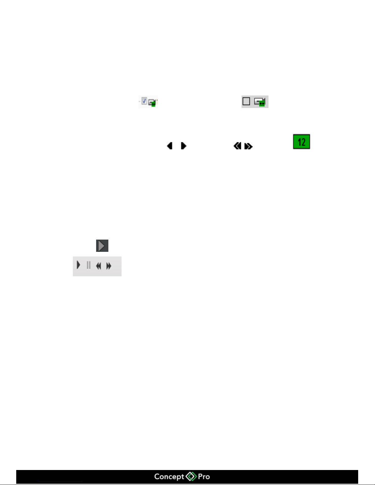
10.3 Live Video
After login via the Web, you can see the live video by selecting the cameras shown in
figure 10-7.
Figure 10-7 Live video
Page 50
46
10.4 Playback
You can play back the video by the playback interface.
Operation Steps
Step 1 Click Playback to enter the playback interface shown in figure 10-8.
Step 2 Select the camera to playback.
Click the camera list, means device was chosen, means device was
not chosen.
Step 3 Select date.
Check the date on the calendar , change month, , change year. This
means the date is chosen. If the date with green colour it means this day has recorded
video.
Step 4 Video play
After the time and date has been selected you can then play the video. The scale on
the time axis showing the recording time period, blue marked line means the current
playback video time. The playback video will be displayed above the time axis, blue
marked means retain video, red marked means alarm video, yellow means label video,
green means normal video.
Step 5 Video play
Click to play video shown in the control bar of figure 10-8.
Play, Stop, Fast Forward, Rewind.
Page 51
47
Figure 10-8 Playback
Page 52
48
10.5 Alarm Search
Click the Alarm Search in the Alarm Management Interface shown in figure 10-9.
Figure 10-9 Alarm search
Step 1 Choose the device on the left that you want to see the alarm information.
Step 2 Choose the alarm type by the bar Type.
Step 3 Choose the date.
Check the date on the calendar , change month, , change year.
This means the date is chosen. If the date with red colour means this day has alarm
video recorded.
Step 4 Video play.
After selecting the device and the date, the alarm file will be displayed below the Type.
And click to begin play video.
Page 53
49
10.6 VHDIPL setup
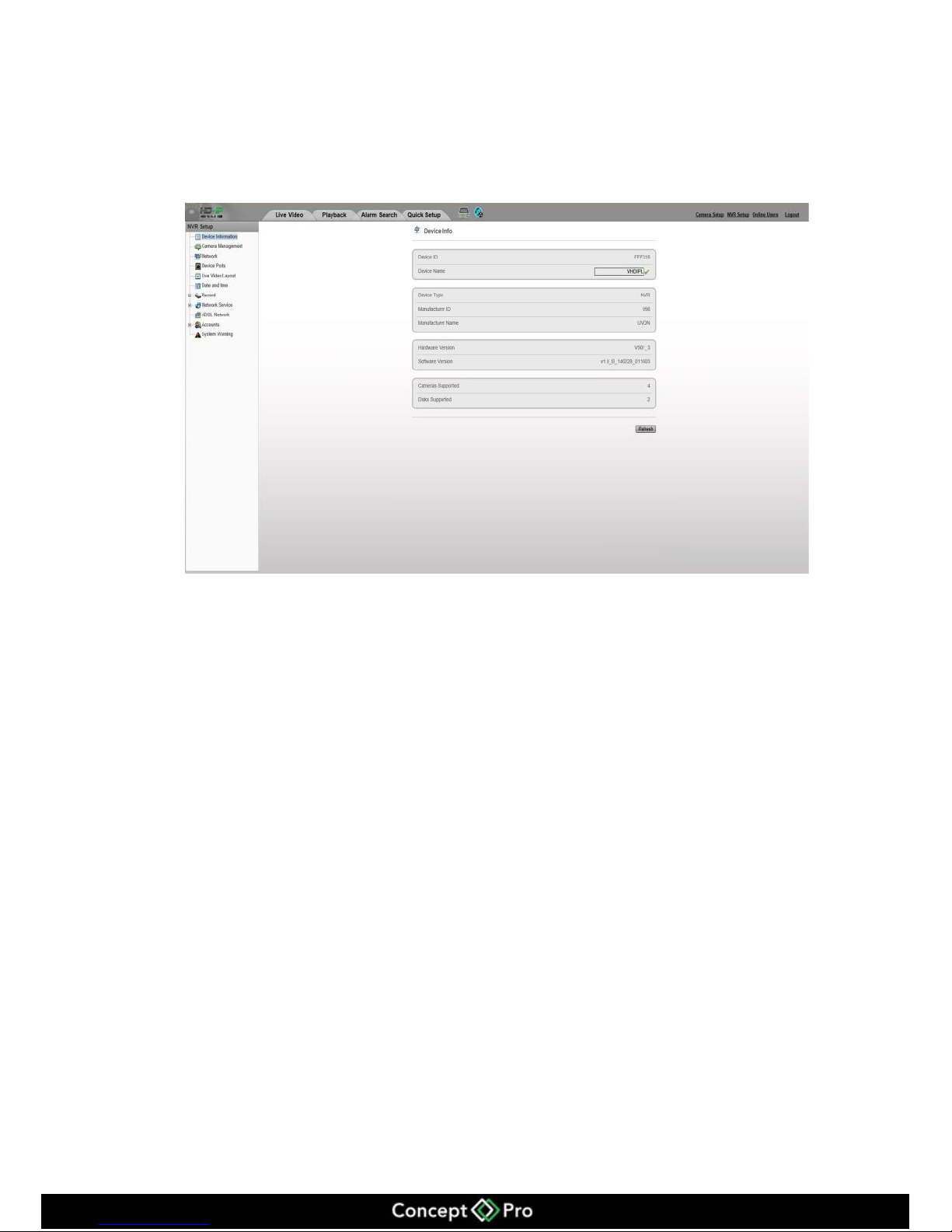
Click the NVR Setup on the web browser enter the VHDIPL configure interface shown
in figure 10-10. For a detailed setup please refer to chapter 9 VHDIPL setup.
Figure 10-10 VHDIPL setup interface
Page 54
50
10.7 Network Camera Setup
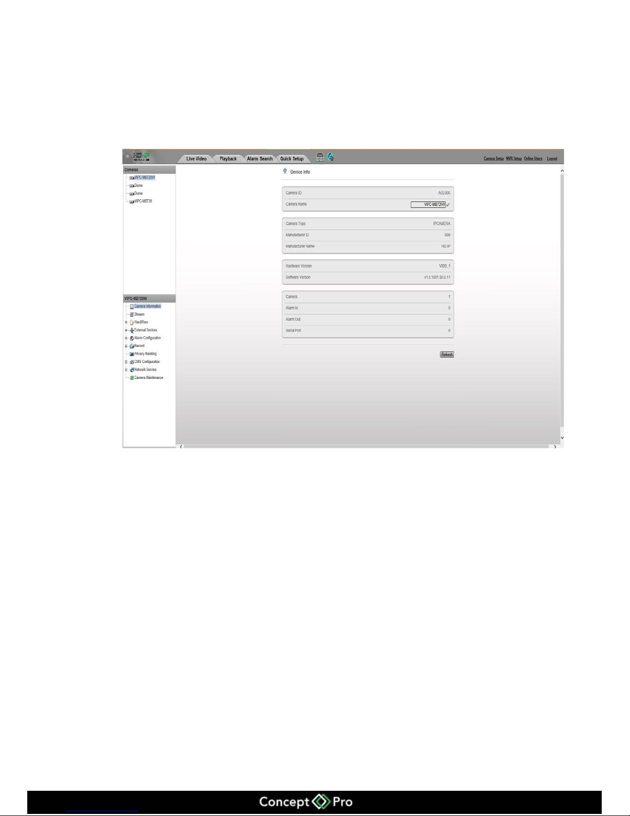
Click the Network Camera Setup on the web, enter the Camera Configuration interface
shown in figure 10-11. For a detailed setup please refer to the VIPC-MD720 and
VIPC-MB720 User Manual.
Figure 10-11 Camera Configure interface
Page 55
51
11 HD-IP Access for VHDIPL
Operation condition
Please install HD-IP client from the USB stick provided. The HD-IP client installation
methods will be in the "Network Video Management System manual”
11.1 Start and Run
If you have installed HD-IP please run it by this icon to the Login interface.
11.2 Login
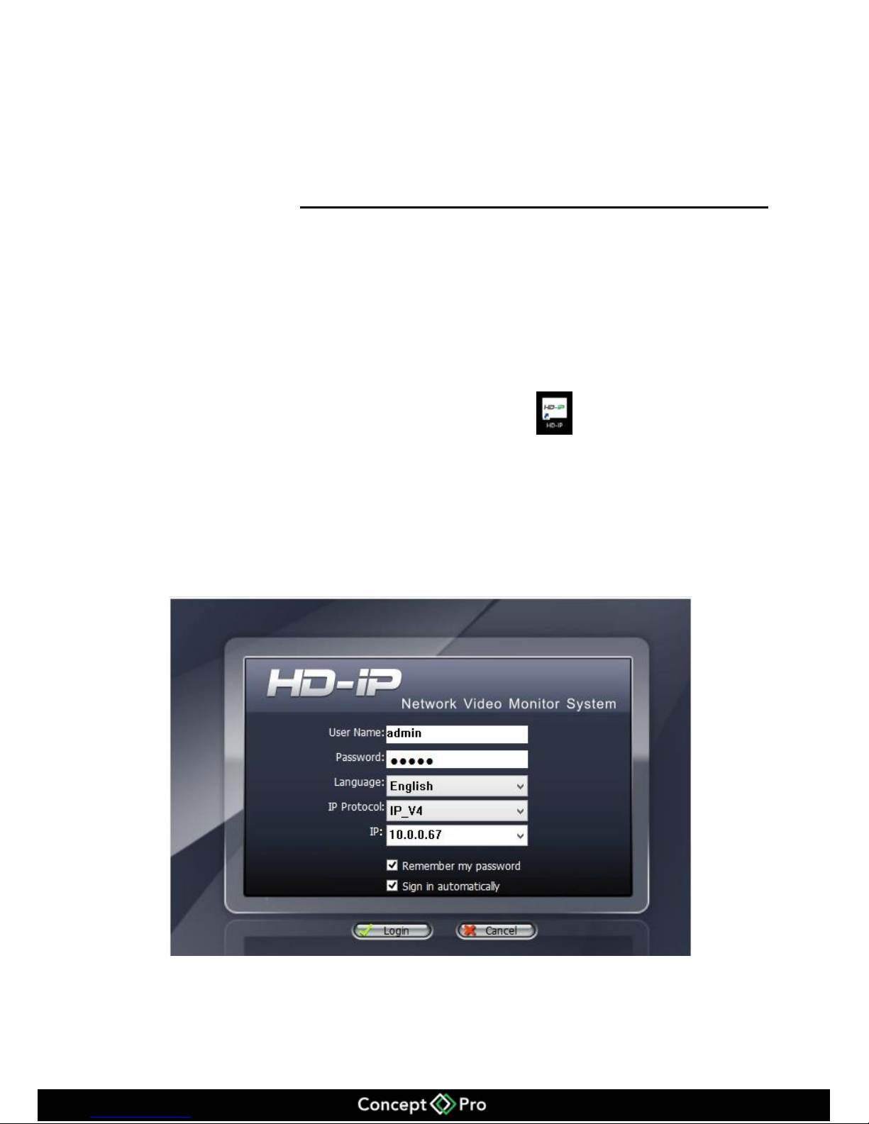
When the Login interface pops up, enter default user name: admin, default password:
admin shown in figure 11-1.
Figure 11-1 Login interface
Page 56
52
11.3 System main interface
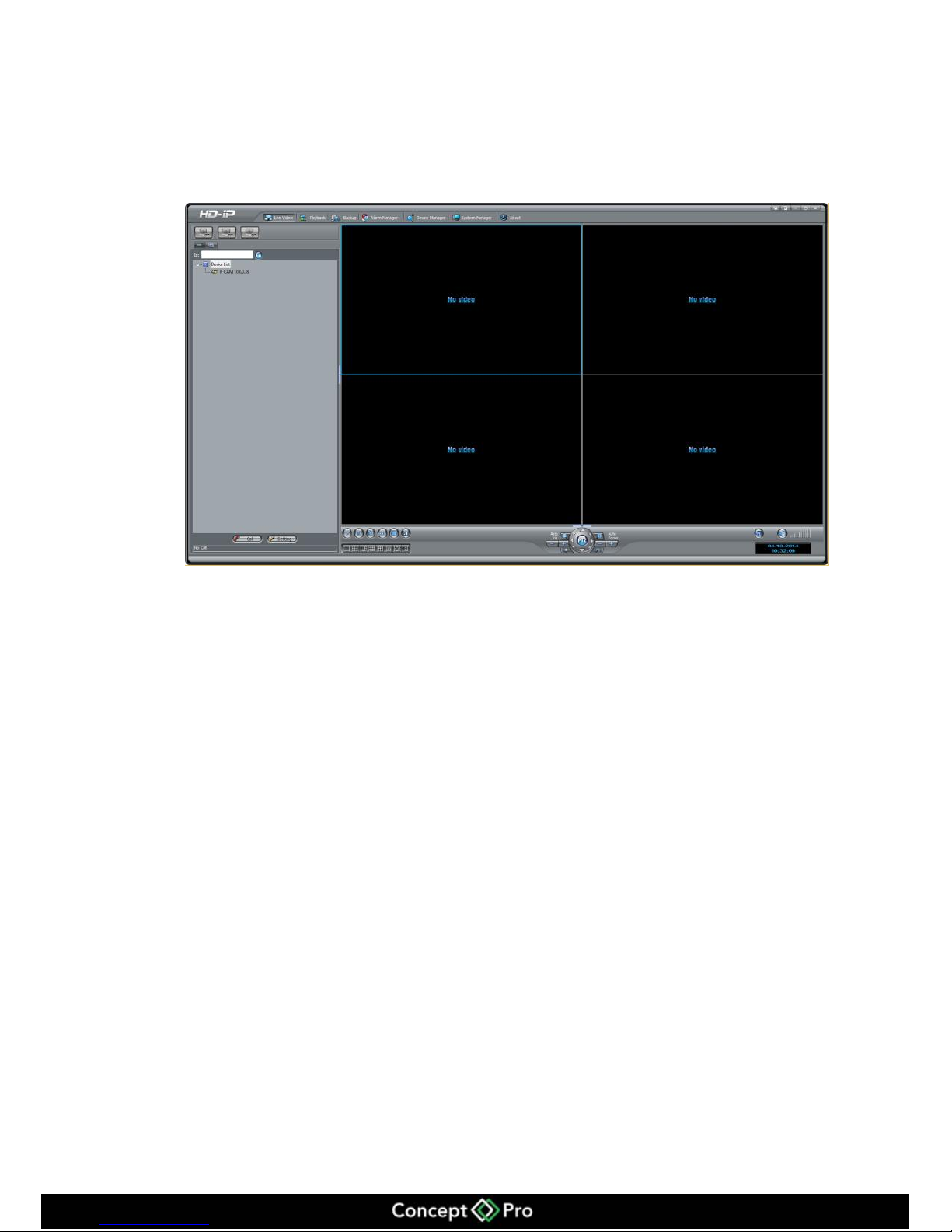
After entering the correct user name (admin) and password (admin), click Login to the
system main interface shown in figure 11-2.
Figure 11-2 Main Interface
11.4 VHDIPL management
After entering main interface, select Device Manager > NVR management go to
VHDIPL configure interface.
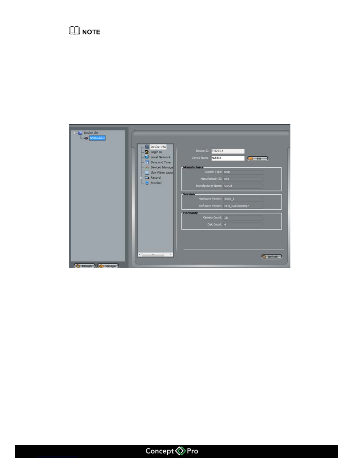
Device Information
Operation description
NVR device information includes:
Device ID and Device Name
Device Type, Manufacturer ID, Manufacturer Name
Hardware Version and Software Version
Camera Count and Disk Count
Page 57
53
Only the Device Name can be edited, other parameters can’t be edited.
Operation Steps
Step 1 Select Device Manager > NVR management > Device Info
The VHDIPL information is shown in figure 11-3.
Figure 11-3 Device info interface
Step 2 Set Device Name, Enter the name and click Set.
Page 58
54
11.4.1 Login
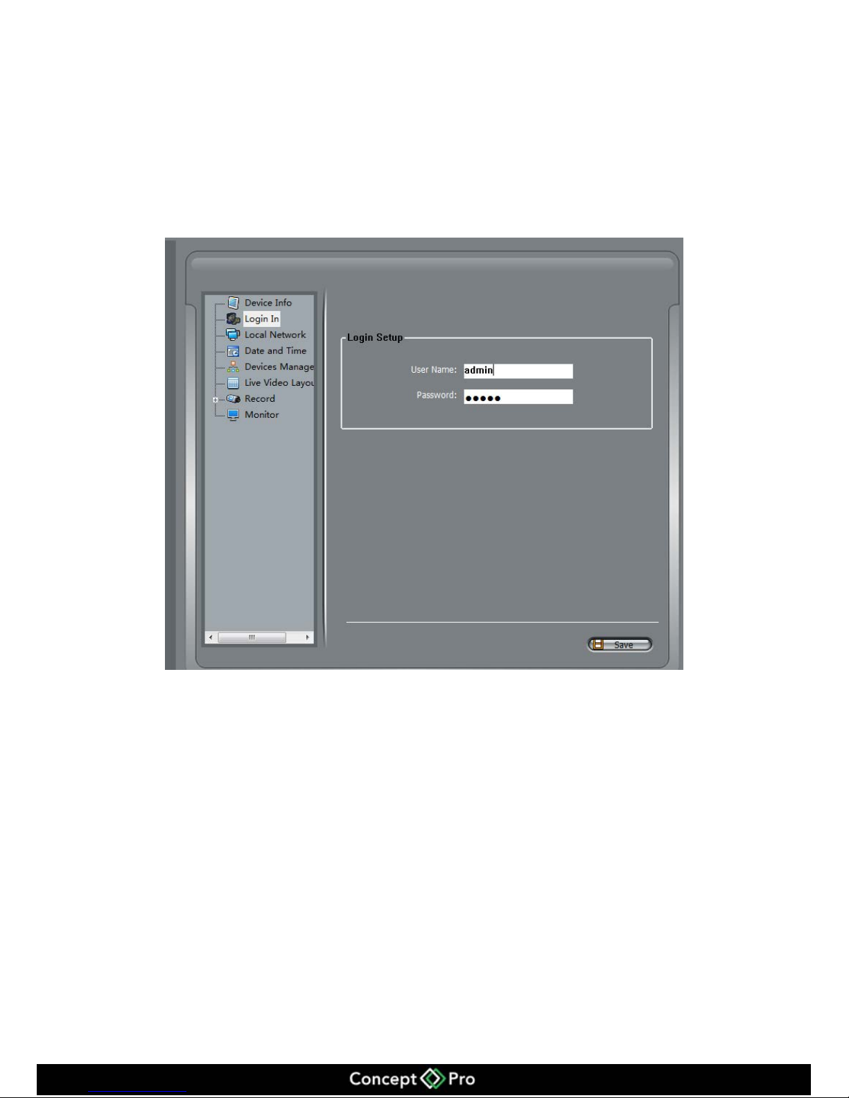
Once logged into the interface you can change the default user name and password.
Operation Steps
Step 1 Select Device Manager > NVR management > Login in to enter the interface shown in
figure 11-4.
Figure 11-4 Login Interface
Step 2 Enter the user name and password, and click Save to exit.
11.4.2 Date and Time
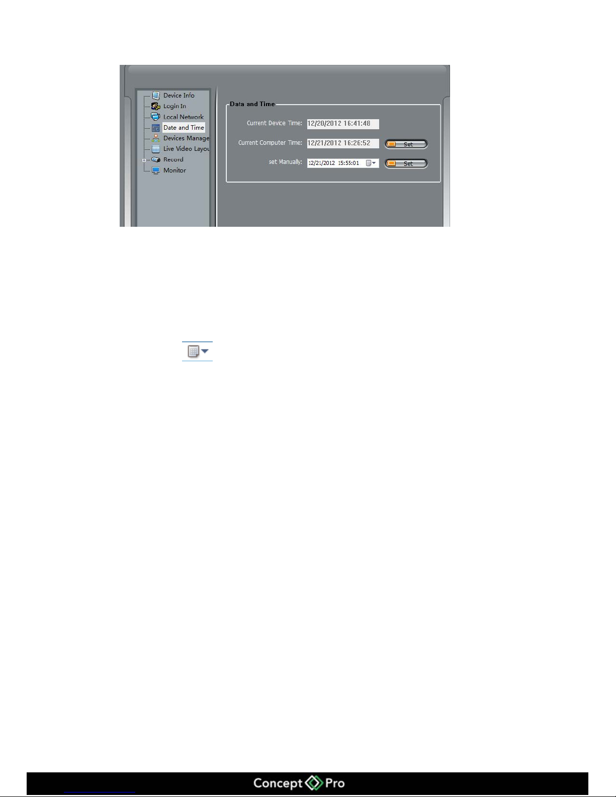
Change the date and time of the VHDIPL
Step 1 Select Device Manager > NVR management > Date and Time, enter configuration
interface shown in figure 11-5.
Page 59
55
Figure 11-5 Date and Time Settings
Step 2 Change the VHDIPL Date and Time
Click the Set button behind the Current Computer Time to sync the time from the PC to
the device.
Set the Computer current time to the VHDIPL time.
Set manually to change time.
Click button to call the date.
Set the date.
Input the time after the date.
Page 60
56
11.4.3 Device Management
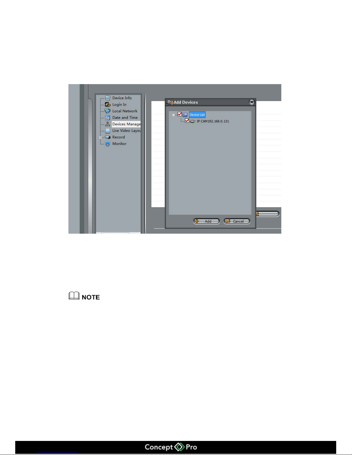
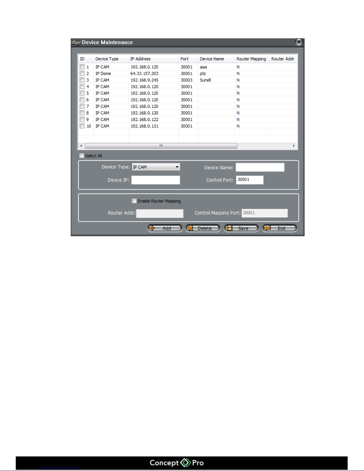
Add/Delete the IP cameras to the VHDIPL through the Device management.
Step 1 Select Device manager > VHDIPL management > Device management enter the
device manager interface shown in figure 11-6.
Figure 11-6 Device Management
Step 2 Select the cameras and click Add.
Call the adding device interface, shown in figure 11-7 to add all the network cameras.
Step 3 Select the cameras which you want to add into the VHDIPL.
Step 4 Click Add to call the added ok message, then click OK, and exit the interface.
Select the devices which you want to delete click delete, the cameras have now been deleted.
Step 5 Click Apply to call the “Configure Successful interface”, click OK to save the
configuration.
Page 61
57
Figure 11-7 Add Device
Page 62
58
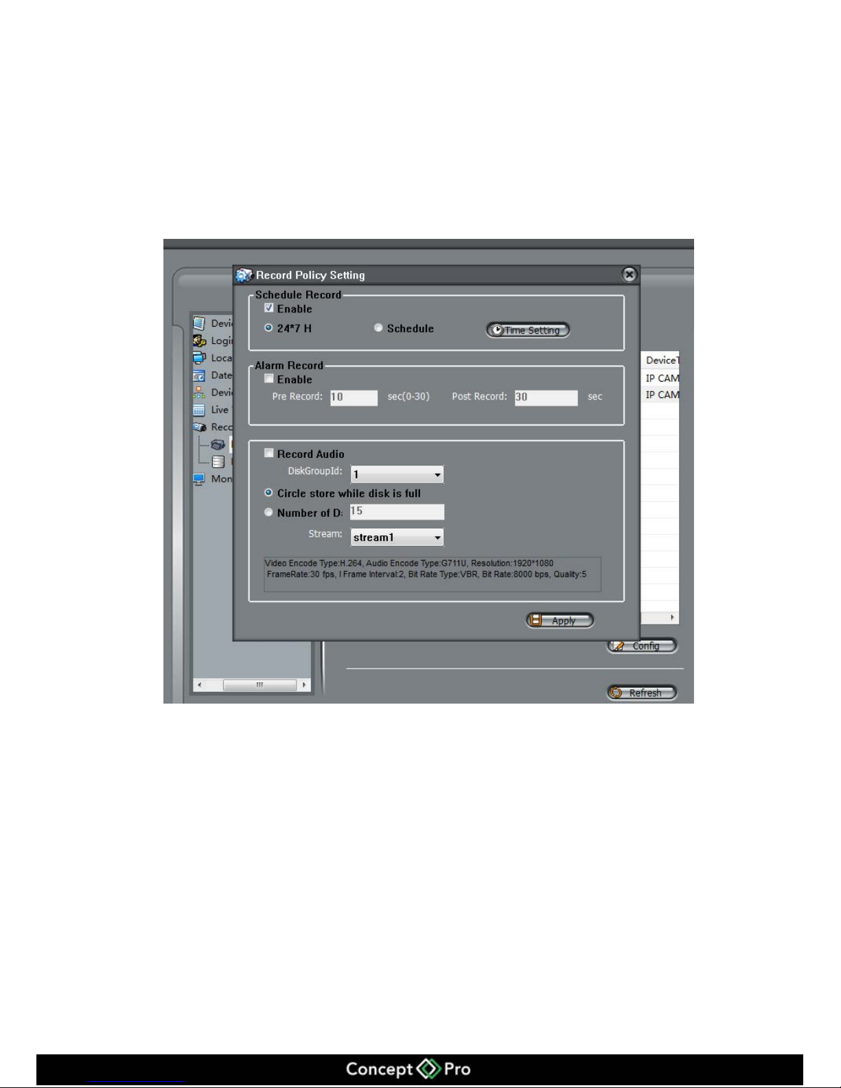
11.4.4 VHDIPL Record
VHDIPL can set the Record Policy and Record Storage.
Record Policy
Step 1 Select Device Manager > NVR management > Record > Record Policy and enter the
Record Policy interface shown in Figure 11-8.
Figure 11-8 Record Policy
Step 2 Select the device and click Configure.
In the Record Policy setting you can set the Schedule Record, Alarm Record, Audio
Record etc.
Step 3 Set the policy which you need.
Step 4 After you set the configuration click Apply to set.
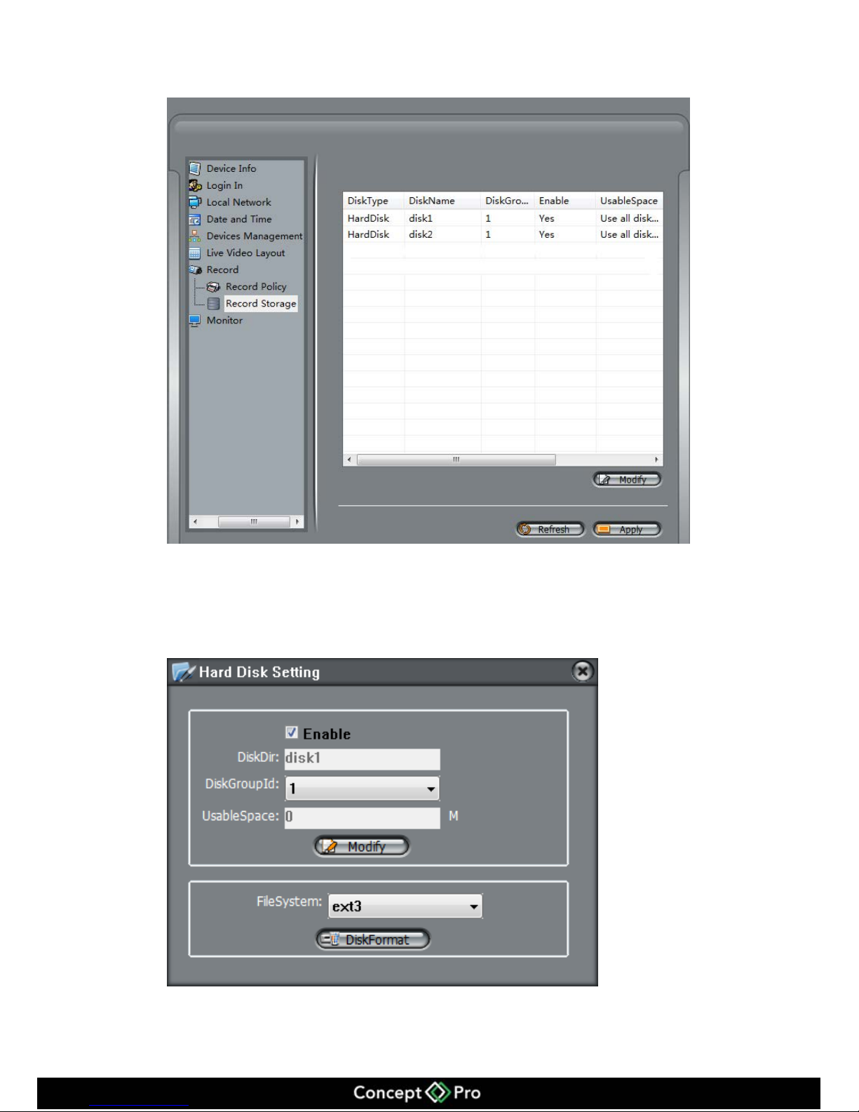
Record Storage
Step 1 Select device manager > NVR management > Record > Record Storage. Enter the
Record Storage interface shown in Figure 11-9.
Page 63
59
Figure 11-9 Record Storage
Step 2 Select the Hard Disk and click Modify enter the path setting interface shown in figure
11-10.
Figure 11-10 Hard Disk Setting
Page 64
60
Step 3 Select Enable.
Step 4 Select the Disk Group ID.
Step 5 Input the Usable Space.
Step 6 Click Modify to save the configuration and exit the interface.
Step 7 Select the file system.
Step 8 Click disk format to format the disk. Confirmation will be required, if yes, then it will
start to format.
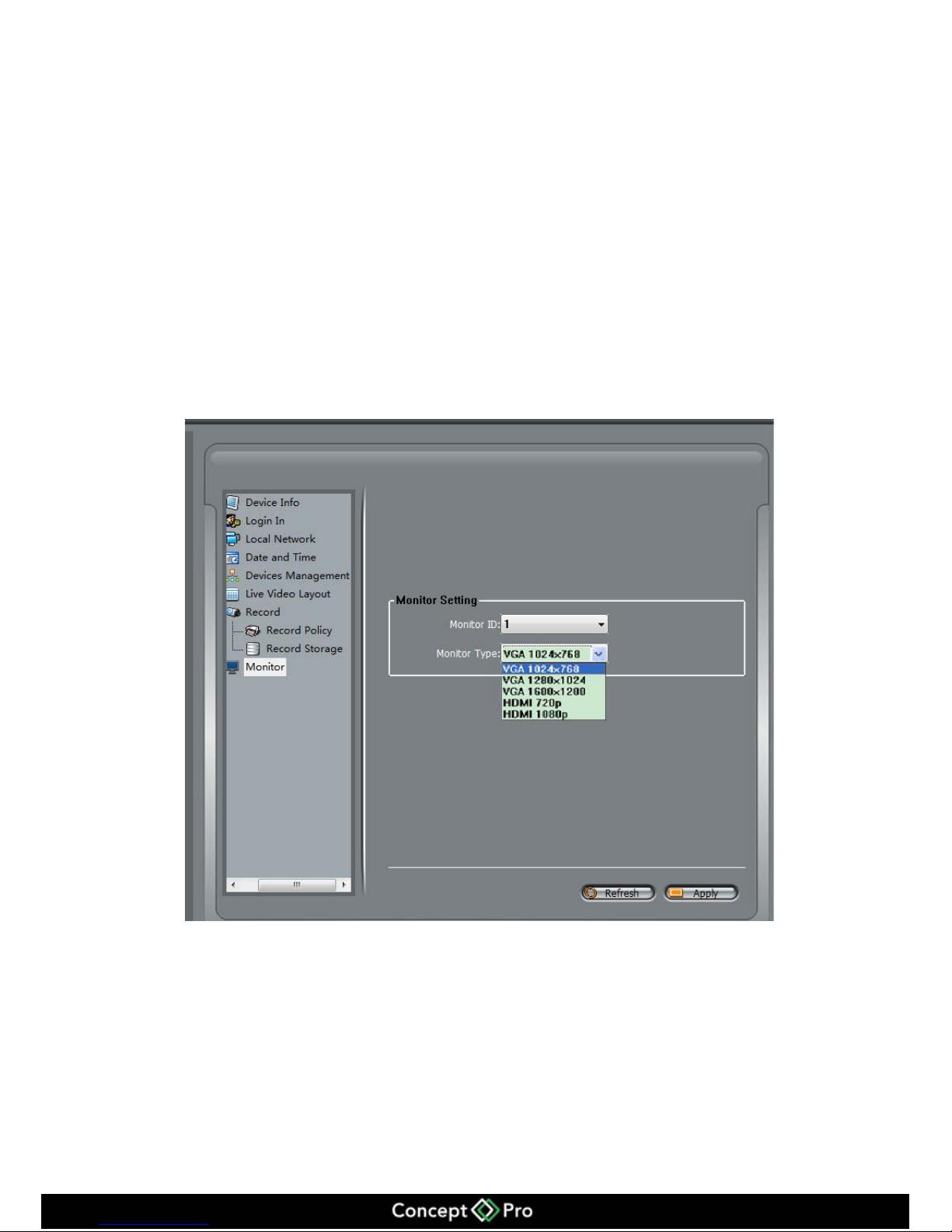
11.4.5 VHDIPL Monitor
VHDIPL rear panel has a VGA output and a HDMI output interface you can adjust the
monitor type shown in figure 11-11.
Figure 11-11 Monitor Configure
After changing the configuration, the VHDIPL will restart automatically.
Page 65
61
11.5 Playback
HD-IP can remotely playback the video from the VHDIPL.
11.5.1 Video Search and playback
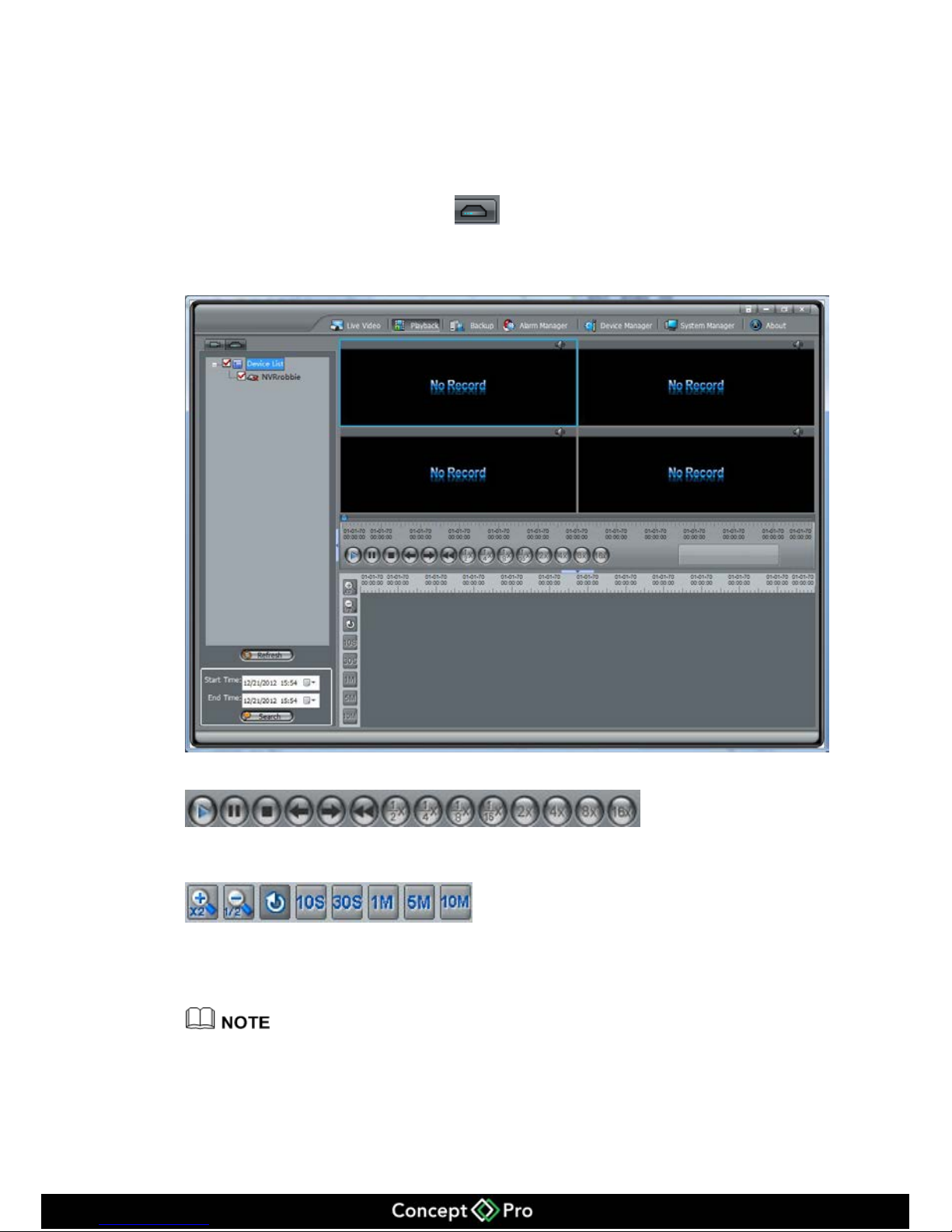
In HD-IP click Playback then click to enter the VHDIPL playback shown in
figure 11-12.
Figure 11-12 Playback
Means: Play, Pause, Stop,
back 1 frame, forward 1 frame, 1/2 fast forward, ¼ fast forward, 1/8 fast forward, 1/16
fast forward, 2 x fast forward, 4 x fast forward, 8 x fast forward, 16 x fast forward.
Means: amplification, narrow, reduction, 10
seconds amplification, 30 second amplification, 1 minute amplification, 5 minute
amplification, 10 minute amplification.
The maximum playback is 16 channels.
Green colour is schedule record, red colour is alarm record. Grey colour is no video.
Page 66
62
11.5.2 Backup
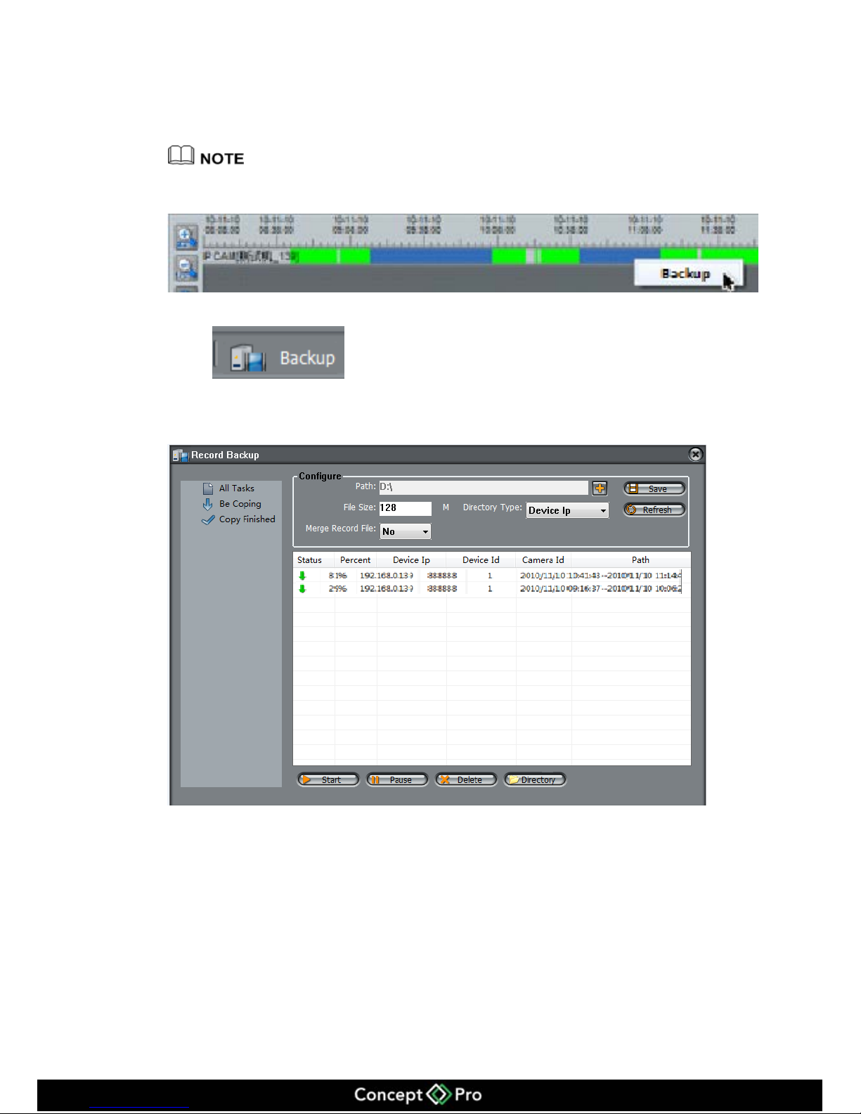
Enter the Backup interface, select the video that needs to be backed up by dragging the
mouse on the time axis and right click, click backup to start the video backup.
Blue file on time axis is the video chosen for backup. Press Ctrl to select more parts of the
video.
Click to backup configure and check the task, setting the path and
backup size shown in figure 11-13.
Figure 11-13 Backup
Click Directory and check the backup file has finished.
Page 67
63
12 NVR Client
You need to install NVR Client on the computer, which is on the UDB stick provided.
12.1 Start and Run
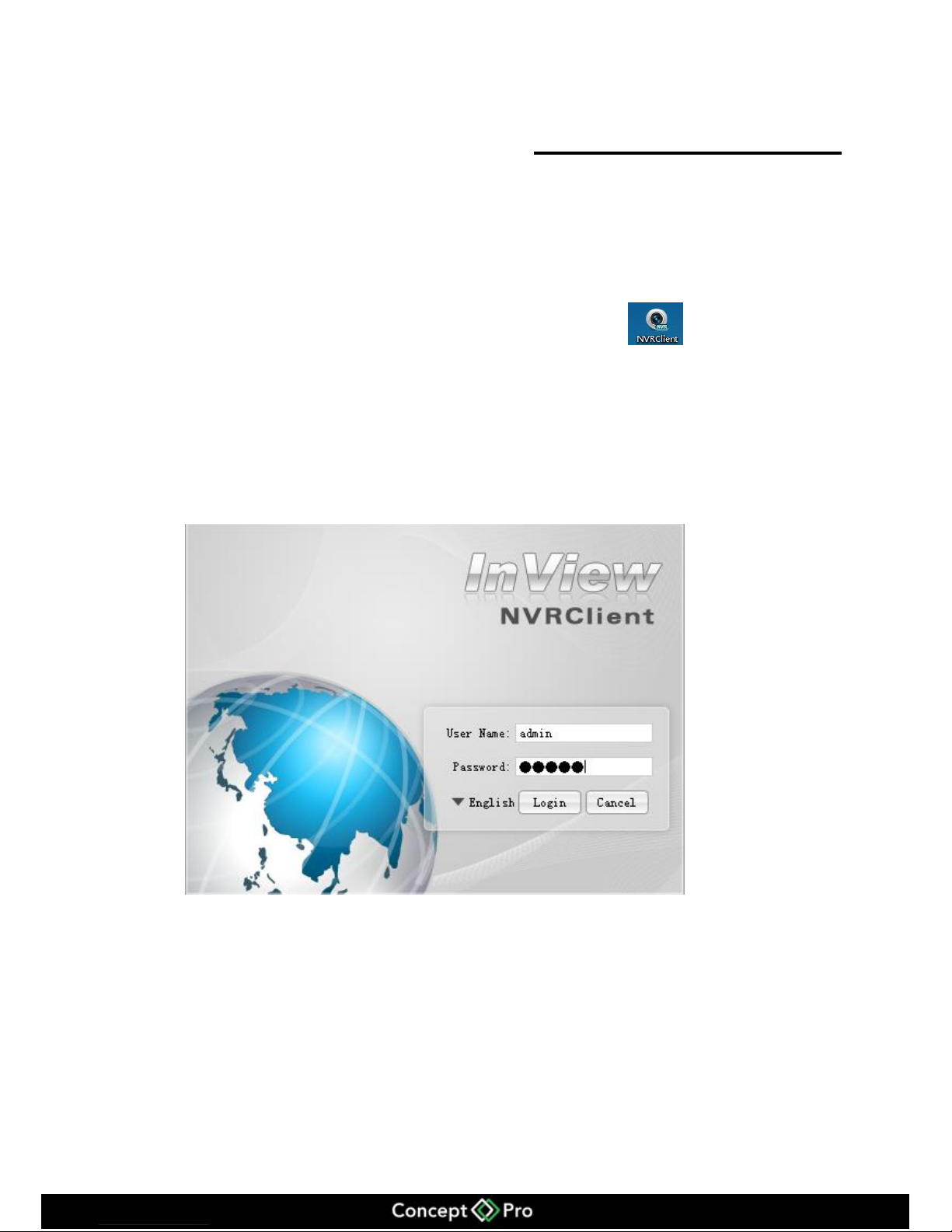
If you have installed NVR Client please run it by this icon .
12.2 Login
When the Login interface pops up, enter default user name: admin and Password:
admin shown in figure 12-1
Figure 12-1 Login interface
12.3 System main interface
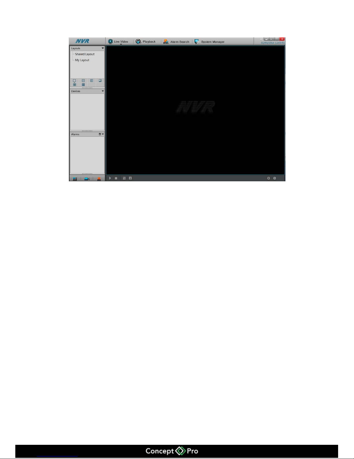
After entering the correct user name and password, click Login to enter the System
Main Interface shown in figure 12-2.
Page 68
64
Figure 12-2 Main Interface
12.4 System Management
After entering the main interface, select System Manager.
12.4.1 Accounts
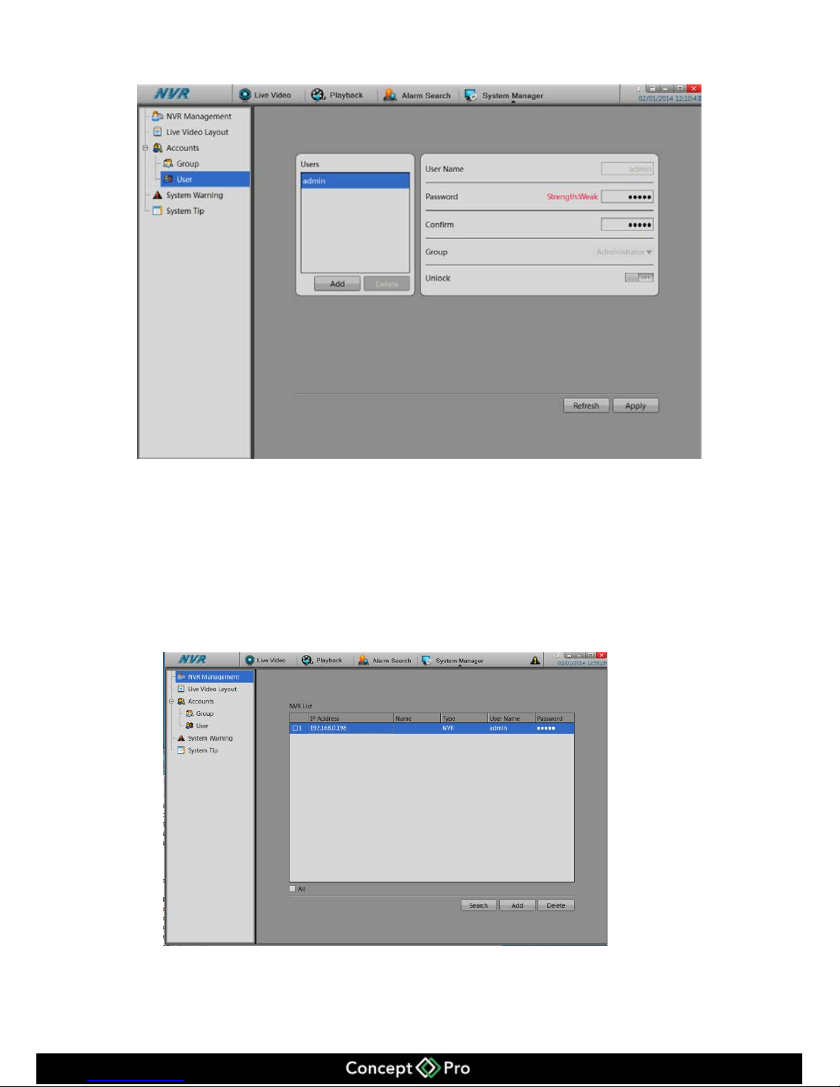
Accounts interface can change the default user name and password.
Operation Steps
Select System Manager->Accounts->User interface shown in figure 12-3
Page 69
65
Figure 12-3 Accounts interface
Enter the user name and password, and click Apply to save.
12.4.2 NVR Management
Add NVR to system.
Select System Manager->NVR management
Figure 12-4 NVR Management
Add NVR by Search or Add manually.
Page 70
66
Click the Search button and then click Scan to search the NVR within the same LAN or
click Add to add the NVR by IP address.
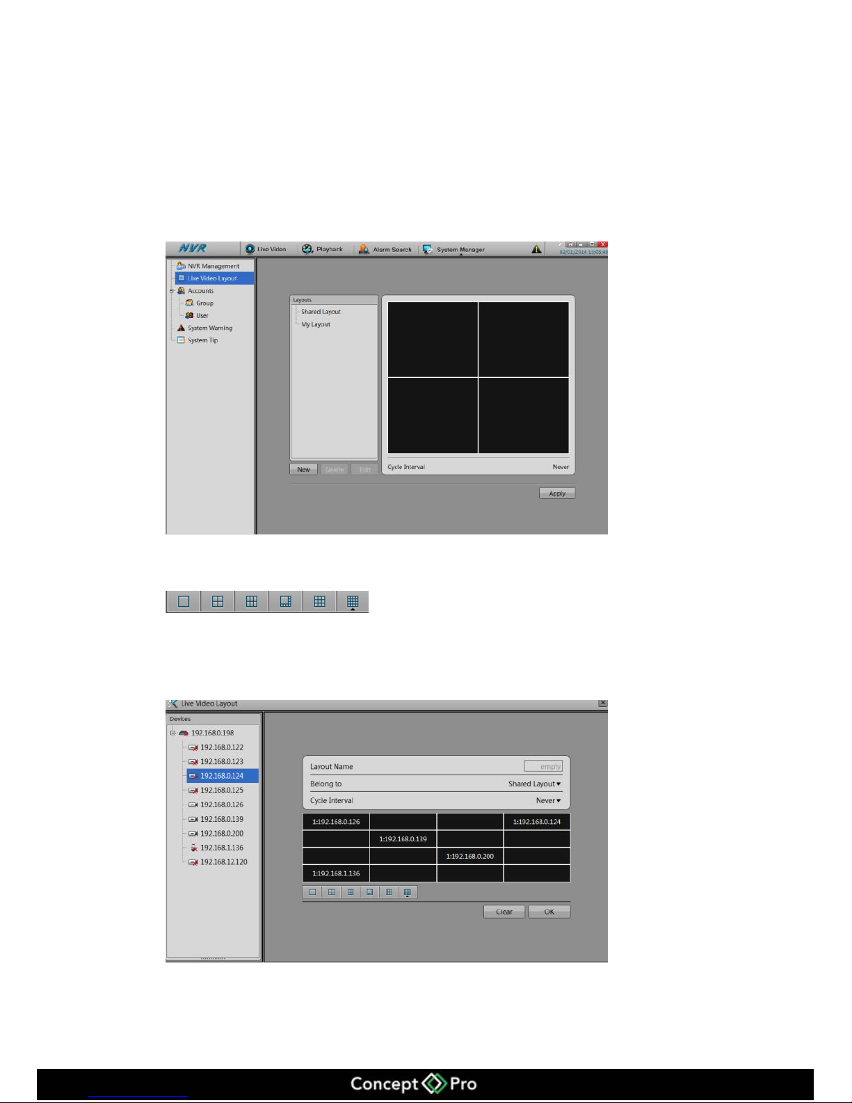
12.4.3 Live Video Layout
Modify the Layout by customize.
Select Device manager->NVR management->Live Video Layout shown in figure 12-5.
Figure 12-5 Live Video Layout
Click New, and select a 1/4/6/9/16 default layout
Select the cameras from the NVR, and drag the camera to the default layout to
customize your layout shown in figure 12-6.
Figure 12-6 Layout
Click OK to save.
Page 71
67
12.4.4 System Warning
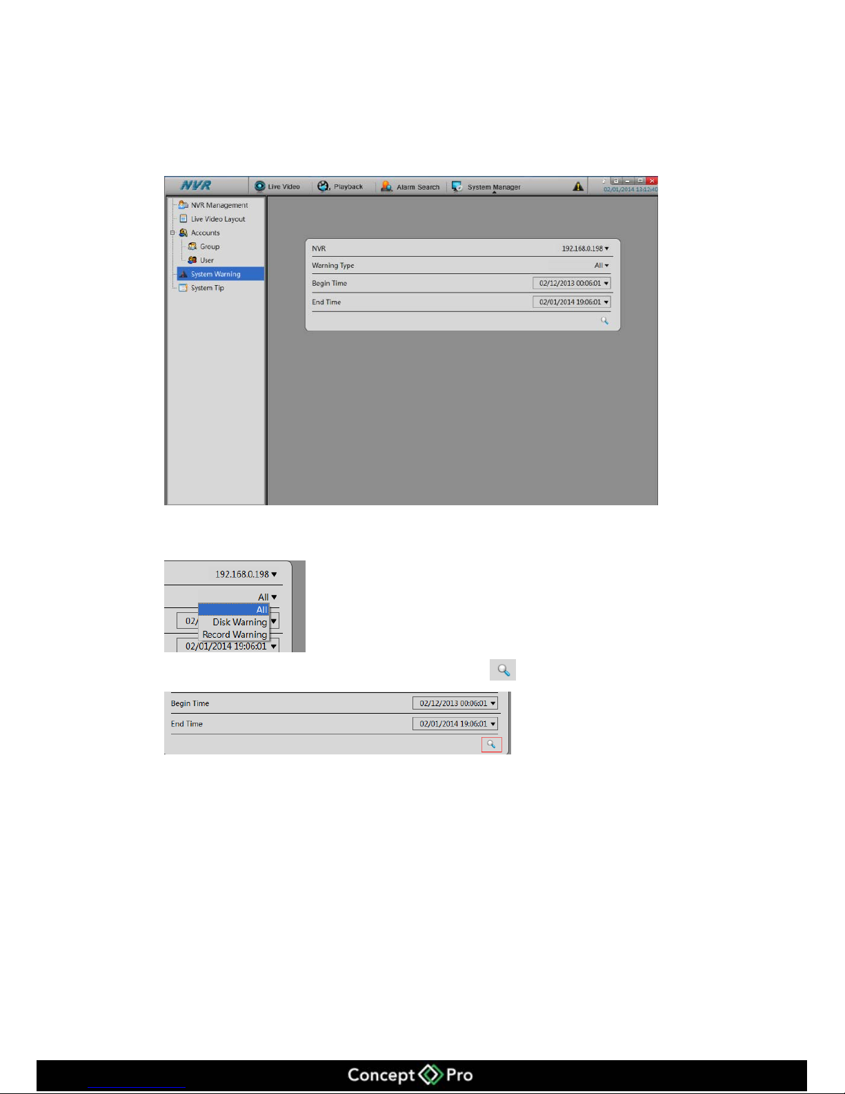
To check the Alarm information, select System Management->System Warning, shown
in Figure 12-7.
Figure 12-7 System Warning
Select the NVR, and select the Type
Set the Begin Time and End Time->Click Search
12.4.5 System Tip
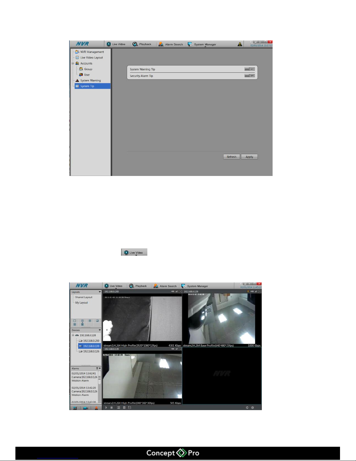
Select System Management->System Tip shown in figure 12-8.
To turn on/off System Warning Tip and Security Alarm Tip.
Page 72
68
Figure 12-8 System Tip
12.5 Live Video and Playback
NVR Client can remotely view live and playback mode.
12.5.1 Live Video
Click Live Video , and drag the camera to the layout for live video show in
figure 12-9.
Figure 12-9 Live Video
Page 73
69
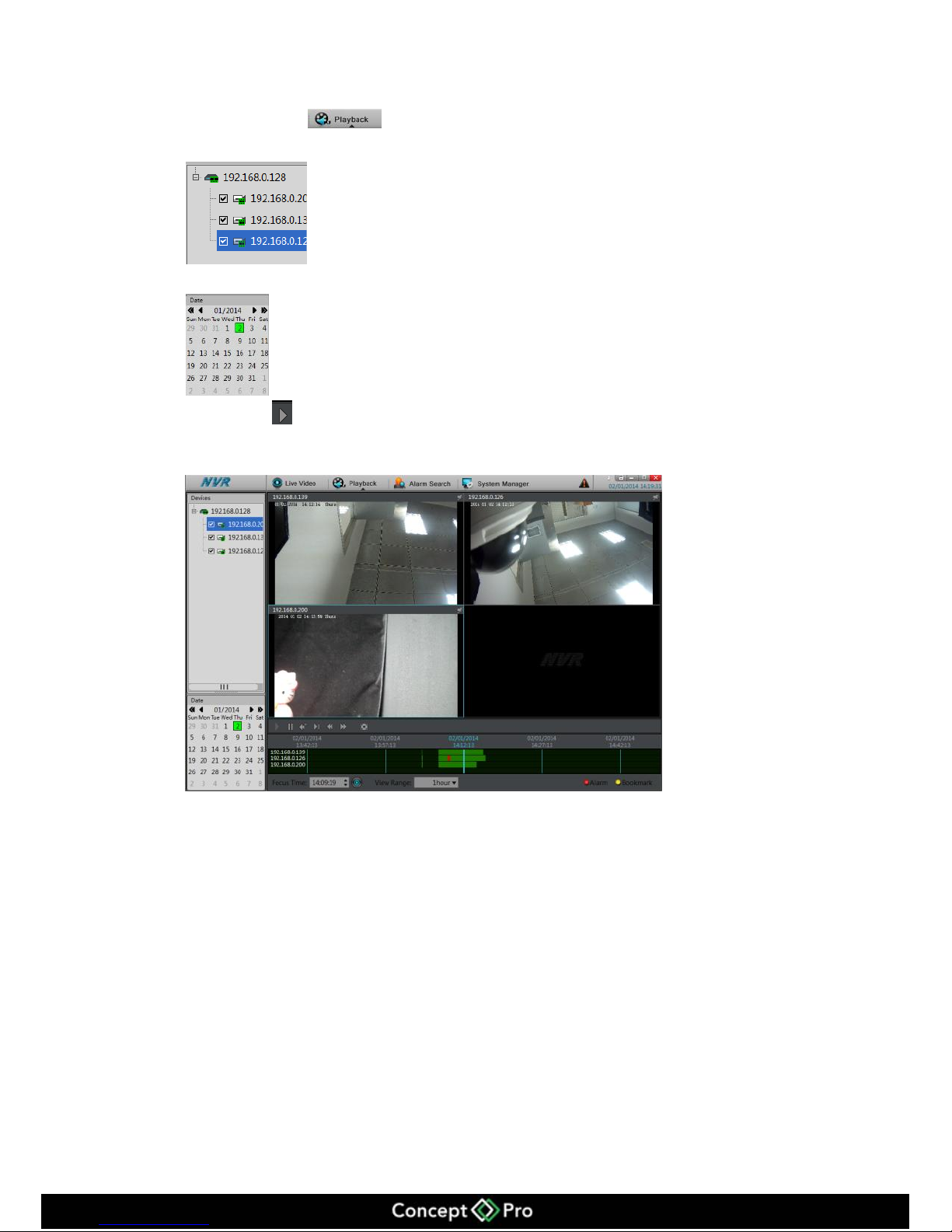
12.5.2 Playback
Click Playback to enter the Playback interface.
Choose the camera
Click the date, if there is a recording then it will be green.
Click Play show in figure 12-10.
Figure 12-10 Playback
Page 74
70
13 HD-IP Lite App
13.1 HD-IP Lite Android device
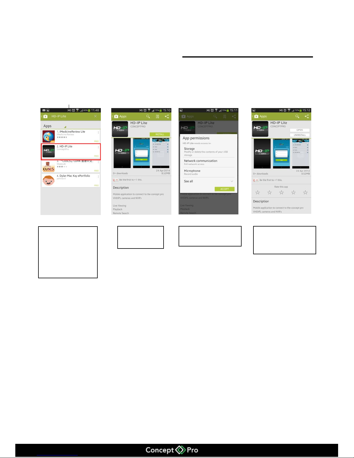
How to download the HD-IP Lite on an Android device
From your smart
phone access the Play
Store and search for
HD-IP Lite.
Select Install
Click on Accept
Once installed click on
Open
Page 75
71
13.2 HD-IP Lite iOS Device
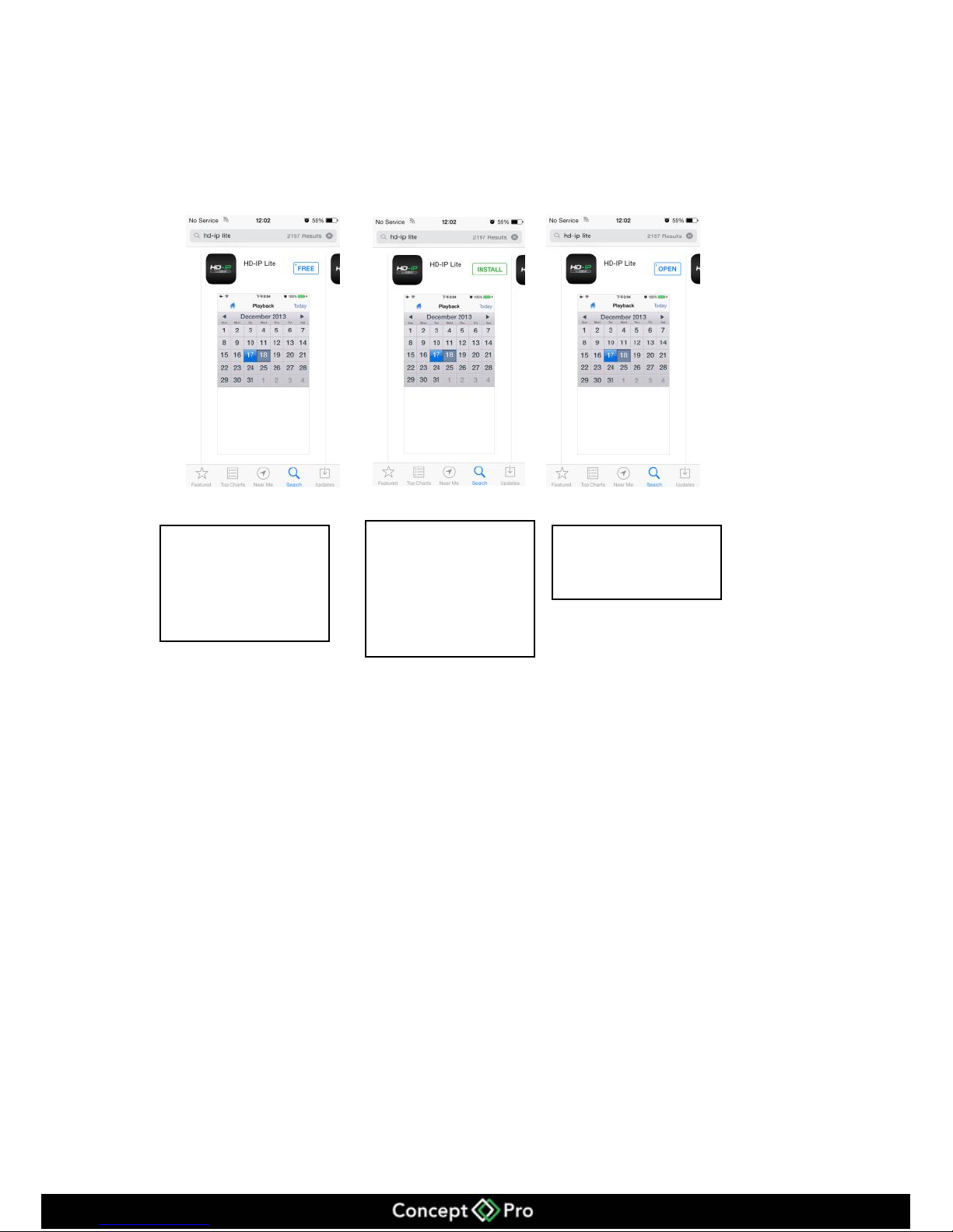
How to download the HD-IP Lite on an iOS device
For more information about the HD-IP Lite app, please see the HD-IP Mobile Viewer
Guide.
From your smart phone
access the App Store
and search for HD-IP
Lite.
Click on Free then
Install to install the
app, you may need to
enter your apple
account details.
Once installed click on
Open
Page 76

72
14 F.A.Q
1. Why does the device’s self-test interface not move?
Method One: Check the VHDIPL is equipped with a HDD.
Method Two: Check the VHDIPL’s HDDs are detected.
Method Three: Check the VHDIPL’s HDDs has not been damaged.
2. Why is the display interface incomplete or
location offset?
Method One: Automatically adjust the display function.
Method Two: In the login screen, select the adjustment, enter the display adjustment
interface.
3. Why can’t the monitor see the image?
Method One: Check the power for the monitor.
Method Two: Check the cable from the monitor to the VHDIPL.
Method Three: Please restart the VHDIPL.
4. Why can I search the network camera, but I am
unable to connect to them?
Please make sure the network cameras and the VHDIPL are in the same subnet.
 Loading...