

Page 1
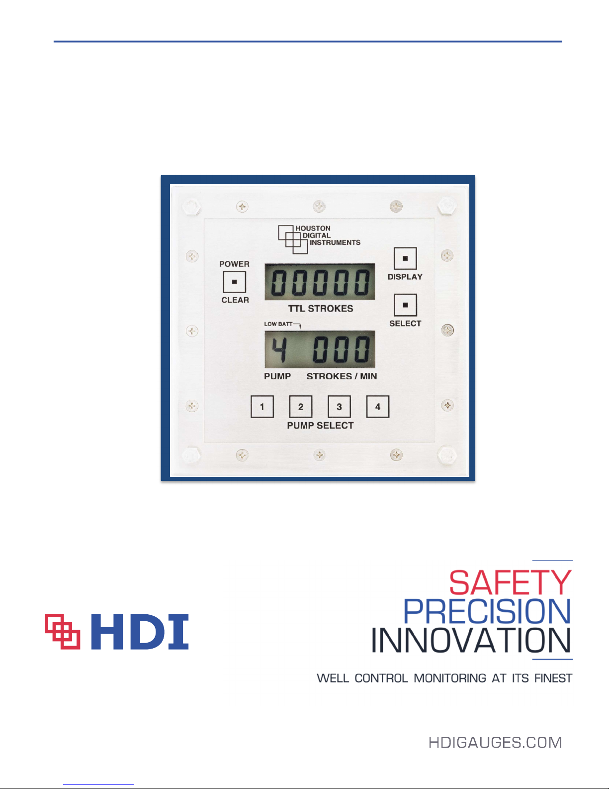
HDI 2100 Pump Stroke Counter
USER'S MANUAL
Revision D
Page 2

Pump Stroke Counter
User’s Manual – 2100, Rev D | Aug 2014
TABLE OF CONTENTS
• Section 1 – Introduction……………………………………………………………….4
1.A General Information
1.B Unpacking and Inspection
1.C Cautionary Information
1.D Personnel Qualifications
• Section 2 – HDI 2100 Pump Stroke Counter System Overview………………..5
2.A Control Head
2.B Power Pack
2.C Pump Stroke Sensors
o 2.C.1 Microswitch Sensor
o 2.C.2 Proximity Sensor
2.D Certification
• Section 3 – Installation………………………………………………………………..8
3.A Control Head
3.B Cable Assembly
o 3.B.1 Microswitch Sensor
o 3.B.2 Proximity Sensor
3.C Sensor Assembly
o 3.C.1 Microswitch Sensor
o 3.C.2 Proximity Sensor
• Section 4 – Maintenance…………………………………………………………….10
4.A Power Pack
4.B Processor Boards
4.C Sensors
4.D Increasing Existing PSC Pump Capacity
• Section 5 – Troubleshooting………………………………………………………..11
5.A Battery Voltage
5.B Simulate Signals
o 5.B.1 Microswitch Sensor
o 5.B.2 Proximity Sensor
5.C Debounce / Main PCB
• Section 6 – Options…………………………………………………………………..12
2
Page 3

Pump Stroke Counter
User’s Manual – 2100, Rev D | Aug 2014
• Section 7 – Technical Overivew……………………………………………………14
7.A General Layout Overview
7.B Sensor Illustrations
7.C Exploded BOM
7.D Common Operational Spare Parts
7.E Proximity Sensor Mounting Brackets
7.F Proximity Sensor Sample Installation
• Section 8 – Warranty…………………………………………………………………21
• Appendix……………………………………………………………………………….22
HDI 2100 Specification Sheet
3
Page 4

Pump Stroke Counter
User’s Manual – 2100, Rev D | Aug 2014
Section 1 – Introduction
1.A General Information
This manual describes the installation, operation, and maintenance of the HDI 2100 Pump
Stroke Counter (PSC) System. This manual provides the user with all the necessary information
to properly operate the Pump Stroke Counter and perform troubleshooting and repair.
The HDI 2100 PSC, like all of HDI’s core products, have three (3) key elements: the Control
Head, a Sensor Assembly specified by the end client, and the Cable Assembly connecting the
Control Head to the Sensor Assembly. These items will be discussed at greater detail in Section
2.
1.B Unpacking and Inspection
Upon receipt of the equipment, it is critical to confirm all the necessary items are accounted as
some items can settle to the bottom of the box or be thrown out/misplaced if previously inspected
by a freight forwarder or third party (Customs) during transit. If any items are missing, contact
the freight forwarder or third party. If there are still missing items, please contact HDI.
1.C Cautionary Information
Power
This system is typically configured with an internal power pack and dry contact sensors that will
be damaged if tested or connected to a 24VDC system without proper modifications from HDI.
Exposed Electronics
Caution: Do not leave the equipment out and unconnected (open cables or display) as this may
expose the connector leads to moisture and outside elements damaging the electronics.
Returns
Proper protection of the equipment should be a top priority when returning the equipment back to
HDI or an authorized agent for repair. Additionally, the shipper must ensure all equipment
clears all Customs duties and inspection as different agencies may hold equipment without
notifying HDI.
4
Page 5

Pump Stroke Counter
UPPER
LOWER
User’s Manual – 2100, Rev D | Aug 2014
1.D Personnel Qualifications
Caution: Anyone testing the equipment should have basic Electronic Technician understanding
and knowledge of electronic circuitry and use of voltage meters. Read the entire manual prior to
opening the display, testing or making any modifications as work performed by personnel without
the proper qualifications may null the warranty.
Section 2 – HDI 2100 Pump Stroke Counter System Overview
The HDI 2100 System is comprised of a Control Head with a Power Pack, a Cable Assembly,
and one or multiple Sensors (Microswitch or Proximity).
2.A Control Head
The Control Head has two (2) LCD windows that display combined total strokes overall, an
individual total count per pump, and strokes per minute (SPM) on each pump.
The upper LCD window displays total strokes for all active pumps as well as total strokes for
each individual pump.
There is a maximum digit display limitation of 65,535 for the total stroke count window. This will
require periodic reset.
The lower LCD window displays each individual pump stroke rate and can toggle between each
active pump. The HDI 2100 is able to monitor up to 4 active pumps.
The Control Head does not have any applicable output options.
Displays the Total Accumulative Stroke count under normal conditions and total count for
DISPLAY
DISPLAY
each individual active pump.
Displays the RATE of the currently selected active pump (in SPM).
5
Page 6
Pump Stroke Counter
A
B
C
D
E
# # # #
User’s Manual – 2100, Rev D | Aug 2014
To Power On: To Power Off:
1. Press Power/Clear Button 1. Press the Select Button once
once. and within four seconds -
2. Press the Power/Clear Button.
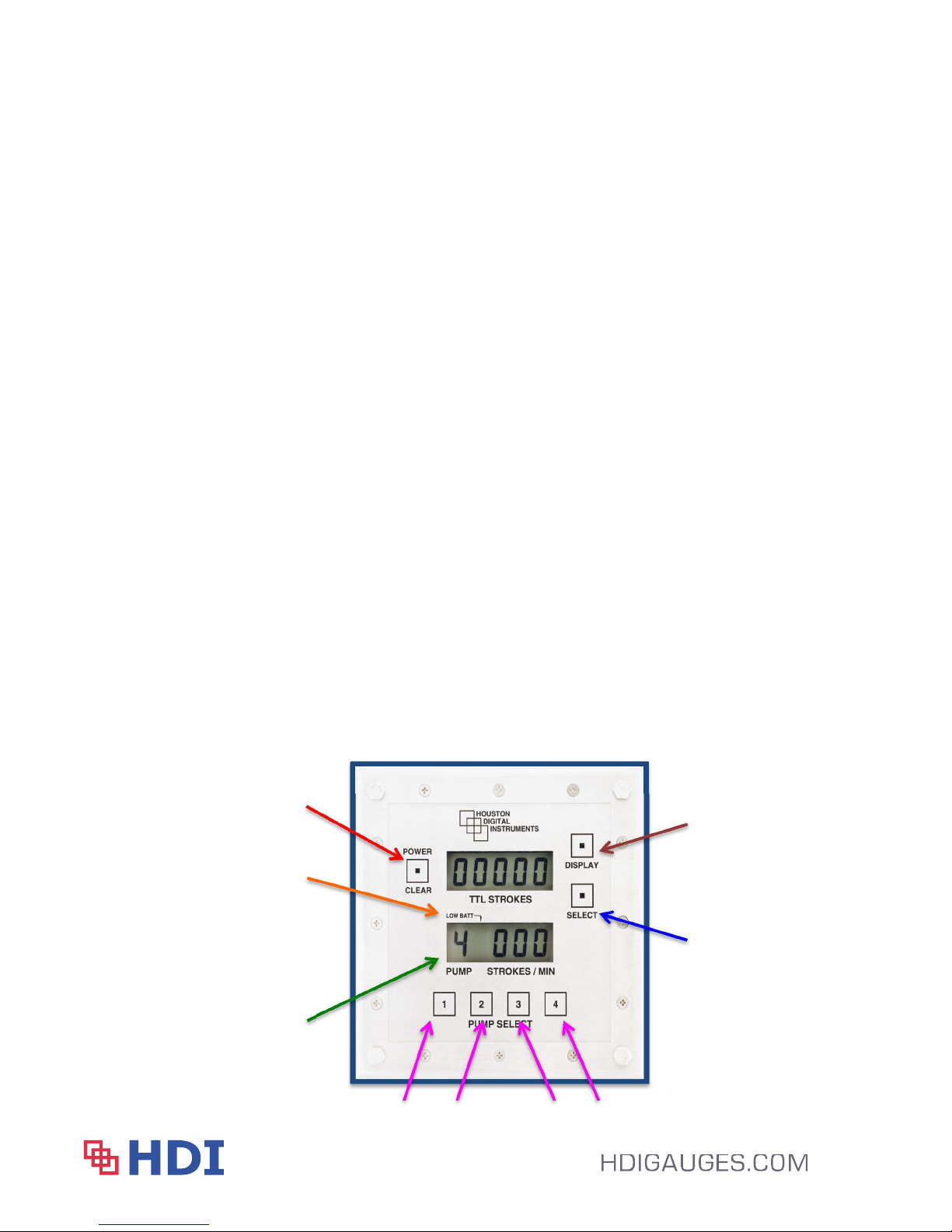
There are seven buttons and two LCD displays on the front panel of the gauge.
1. Power / Clear Button (A) – multifunction button to power on or off the gauge. Also
clears the displayed total strokes and/or individual pump stroke count seen on the top
screen.
2. Battery Indicator (B) – battery symbol is displayed when the power voltage drops below
3.x VDC so the user is able to secure a spare / replacement. The symbol appears when
the battery has roughly 30-45 remaining days of use.
3. Pump Monitored (C) – displays the active pump being monitored. This format is also
used in the upper window if an individual pump is being displayed to show an individual
pump’s stroke total.
4. Display (D) – toggles the top screen between Total System Strokes and Individual Pump
Strokes. If the unit only has 3 active pumps, the user will see Zero (0) when toggling the
upper display to Pump 4.
5. Select (E) – toggles in between pump functions.
6. Pumps (#s) – Used to toggle lower screen between different pumps.
“1” – represents Pump 1 “2” – represents Pump 2
“3” – represents Pump 3 “4” – represents Pump 4
6
Page 7
Pump Stroke Counter
User’s Manual – 2100, Rev D | Aug 2014
2.B Power Pack
The unit has an internal Power Pack with a 3.6 VDC source.
2.C Pump Stroke Sensors
The signal generated by the sensors is a simple contact closure. As the pump cycles across the
magnet or the contact switch, the contact closure is sensed by the Control Head allowing both
total strokes and strokes per minute to be displayed. The HDI 2100 Pump Stroke Counters are
capable of detecting and monitoring a minimum stroke per minute (SPM) rate of 11 SPM and a
maximum of 300 SPM.
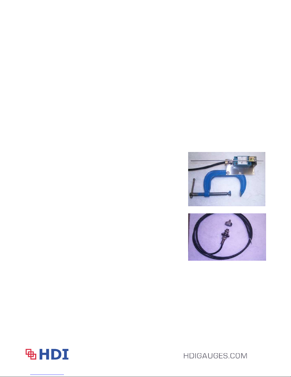
There are two different sensor configurations show below. Further detail is found in Section 7.
2.C.1 Microswitch Sensor
The Microswitch is a standard limit switch
with a contact lever box, wand, and a 5” C
Clamp. The contact lever box comes with a
½” NPT gland entry.
2.C.2 Proximity Sensor
The Proximity Sensor is comprised of a
magnet assembly, an all thread pick up sensor
stem, and a mounting bracket.
2.D Certification
The HDI 2100 Pump Stroke Counter is certified by CSA as Intrinsically Safe for Class I Div 1
Groups A – D and ATEX Certification is available upon request.
7
Page 8

Pump Stroke Counter
User’s Manual – 2100, Rev D | Aug 2014
Section 3 – Installation
3.A Control Head
The Control Head can be mounted from either the front or back of a control panel console. The
Control Head comes with four (4) ¼-20 Bolts and Lock Nuts used for mounting.
If the LCD is mounted from the front of the panel, the user will remove the Lock Nuts, drop the
Control Head into the panel/bracket, and secure it by threading the Lock Nuts back onto the ¼20 Bolts.
If the LCD is mounted from the back of the panel, the user will remove the ¼-20 Bolts from the
Control Head. Then, place the Control Head in line with the holes on the panel or bracket and
place the ¼-20 Bolts back through the console to the Control Head. The Lock Nuts will not be
needed as the Control Head has threaded holes.
Caution: Take care to not over tighten the Bolts as cracking the Front Lens is possible.
3.B Cable Assembly
The Cable Assembly, by default, is arranged differently depending on the type of Sensor
ordered. Cable lengths are ordered in increments of five (5) feet.
3.B.1 Microswitch Cable
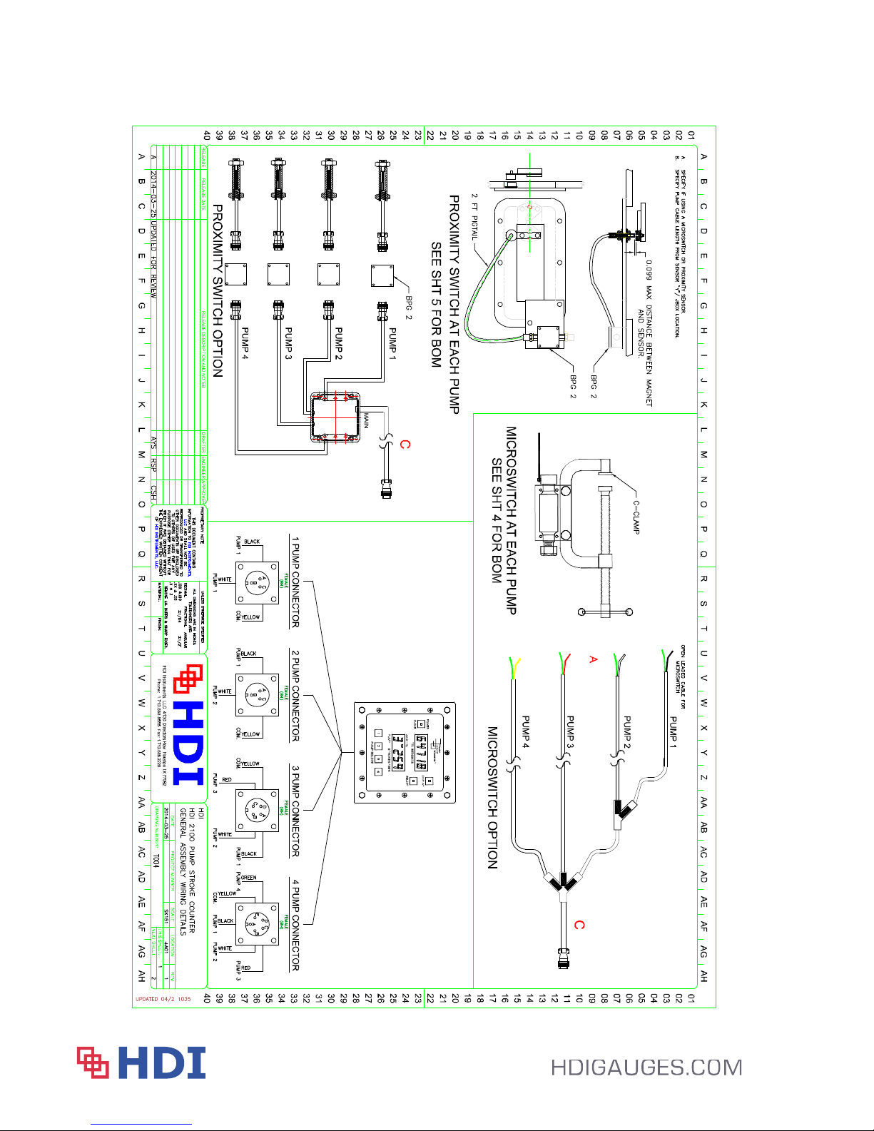
The Cable Assembly is configured into a “Y” configuration with each pump leg being the
shorter sections of the “Y” with the main stem of the “Y” representing the main cable from
the Control Head to the “Y” split. By default, the pump legs are identical lengths;
however, based on final wiring, adjustments can be made locally to shorten each pump
leg to the proper length. The Microswitch pump legs are combined into a permanent 3M
epoxy splice kit at the “Y” split combining the legs together before being routed to the
Control Head.
8
Page 9

Pump Stroke Counter
User’s Manual – 2100, Rev D | Aug 2014
The Microswitch assemblies are pre-connected to the “Y” cable assembly and may
require the cable to be disconnected from the contact lever box ½” NPT gland so the
cable assembly can be routed into the cable trays.
3.B.2 Proximity Cable
The Cable Assembly is routed through a local J-Box in the Pump Room. There will be
one cable from the Control Head to the J-Box, and from the J-Box to the Sensor, there will
be a cable for each pump being monitored, these cables are referred to as the pump legs.
3.C Sensor Assembly
3.C.1 Microswitch
The switch assembly has the contact lever box, wand, and C clamp. The C Clamp
mounts to the adapter plate for easy installation.
3.C.2 Proximity
In order to install the proximity sensor onto the pump shaft properly, the user will need to
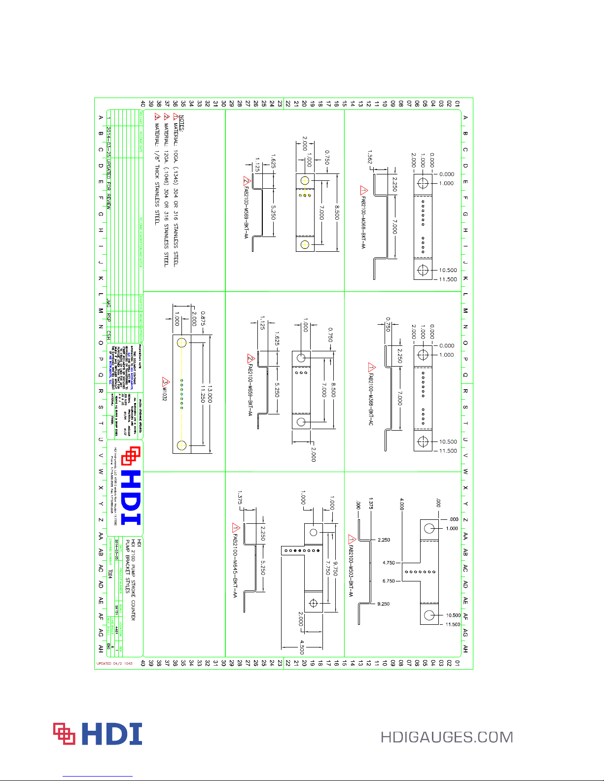
know the specific pump model and manufacturer being monitored so that HDI can review
its list of existing fabricated brackets. See current available bracket list provided by HDI
in Section 7.E of this manual.
Note: The proximity sensors require careful measurements to ensure proper installation.
The Sensors can double stroke on the out and return stroke. The all
thread pick up sensor stem is assembled with a 2’ pigtail and a connector. The mating
cable assembly has an open lead for local junction box termination. Please review the
appendix for an example step-by-step guideline on how to properly install the proximity
sensors based on the Wirth 2200 Series pumps.
The all thread stem and magnet should be adjusted so the components are no more than
1.25” apart. Typical installation would leave a ½” – ¾” gap when properly installed.
Prior to closing up the inspection plate, review the details to ensure no potential damage
will be caused by having the all thread stem and magnet positioned too close together.
9
Page 10

Pump Stroke Counter
User’s Manual – 2100, Rev D | Aug 2014
Special attention should be observed when replacing a proximity sensor assembly to
ensure the sensor is properly adjusted to pick up the pulses as the pump strokes.
Section 4 – Maintenance
The HDI 2100 Pump Stroke Counter System will require the following periodical maintenance.
4.A Power Pack
The System is powered by an internal 3.6VDC power pack that is warranted for 12 months from
the date of shipment. On average, the power pack will last 18 months based on 24 / 7 operation;
however, if the user is able to turn off the unit when not in use, the battery life can be greatly
extended.
4.B Processor Boards
The LCD has two (2) internal processor boards: the HDI 012 and the HDI 02 debounce
processor board, both of which can be replaced in the field if either component has failed. In the
event there is an issue with a specific pump’s SPM rate, the user may be able to simulate signals
to help isolate which PCB has failed. Section 5 provides some basic troubleshooting tips.
Additionally, please contact HDI Technical Support for additional suggestions.
4.C Sensors
Depending on the pump configuration, either sensor type can be replaced as a full assembly kit
or partial components based on what components have been damaged or have been found
faulty. See related Section 7 BOM illustrations.
4.D Increasing Existing PSC Pump Capacity
To increase the number of pumps on an existing PSC, a pump sensor kit will need to be
purchased. The kit includes a spare sensor (Proximity or Microswitch) with specified cable. The
bulkhead connector on the back of the Control Head and the mating connector for the cable
assembly must be replaced; the replacement connectors are shipped with the pump sensor kit.
In addition, if the pump legs are joined together with a 3M-splice kit, the user will have to cut the
legs, remove the splice and replace it with a J-Box. The J-Box is also included in the pump
sensor kit.
10
Page 11

Pump Stroke Counter
User’s Manual – 2100, Rev D | Aug 2014
Section 5 – Troubleshooting
5.A Battery Voltage
The System effectiveness and accuracy is impacted when voltage of the power pack drops
below xxx VDC. Once the voltage drops below xxx. VDC, the battery indicator symbol will
accent on the display providing the user a warning / notification to source a replacement. This
will provide the user with a 30-45 day advance notice to obtain a replacement. See Section 2.A
for the battery symbol location.
5.B Simulate Signals
In the event a faulty sensor assembly or main PCB board assembly is failing, the user is able to
simulate signals to isolate the failed component. Be sure to clear out both Total Strokes and all
individual Pump Strokes prior to testing to verify results.
5.B.1 Microswitch
Using a flat head screwdriver to twist the rod to simulate a stroke, the installation
can be tested to see if the pump’s contact point is properly striking the Microswitch
sensor. If simulating the stroke displays properly on the Control Head, the pump’s
contact point is not making contact with the rod. Adjust rod/sensor location to allow the
rod to be properly struck during each pump stroke.
Opening the contact level box on the Microswitch Sensor is another way to test the
Microswitch Sensor. By tapping the White and Black wire leads, found inside the contact
level box, the user can simulate a stroke. If the Control Head registers a stroke, the
Microswitch Sensor will need to be replaced.
5.B.2 Proximity
Troubleshooting the Proximity Sensor will require the user to open up the local J-Box in
the pump room. At the local J-Box, the user can tap the Black and White wire leads to
simulate a stroke back to the Control Head. If a stroke is seen on the Control Head, the
Proximity Sensor will need to be replaced.
11
Page 12

Pump Stroke Counter
User’s Manual – 2100, Rev D | Aug 2014
5.C Main PCB / Debounce:
The user can also conduct a similar test to the Sensor tests above; directly on the PCB or
Debounce Board found within the Control Head. Using the pin details listed below, the user can
simulate strokes. The test will allow the user to determine whether a new PCB or Debounce
Board is needed. If the system being tested has an available spare connection on the PCB, the
user can move the signal over to test on the input another pump. For example, if the System is
a 3 pump unit and pump 2 isn’t displaying correctly, move the white wire to pump 4 to test.
Each System’s pump configuration is different. Please review the table below which identifies
each System’s wiring configuration for testing. Test either board by tapping the faulty pump’s
wires with the common. For example, to test Pump 2 on a 2 Pump System, tap the pins B and
C.
1 Pump 1 Pump 2 Pump 2 Pump 3 Pump 3 Pump 4 Pump 4 Pump
Pin A Black P1 A - B Black P1 A - C Black P1 A – D Black P1 A – E
Pin B White White P2 B - C White P2 B – D White P2 B – E
Pin C Green Red P3 C – D Red P3 C – E
Pin D Green Common P4 D – E
Pin E Green
Section 6 – Options
Backlight and External Power
The System can be modified to add backlighting and the unit can be powered by an external 12
or 24VDC power source provided basic precautions and barriers are used. Please note, these
two options can be carried out in the field after the fact but are costly to do so as the internal
components would be replaced.
Output
HDI offers dual proximity sensors in one all thread stem allowing the signals to be split to the
Control Head and an HMI or secondary remote display.
12
Page 13

Pump Stroke Counter
User’s Manual – 2100, Rev D | Aug 2014
13
Page 14
Pump Stroke Counter
User’s Manual – 2100, Rev D | Aug 2014
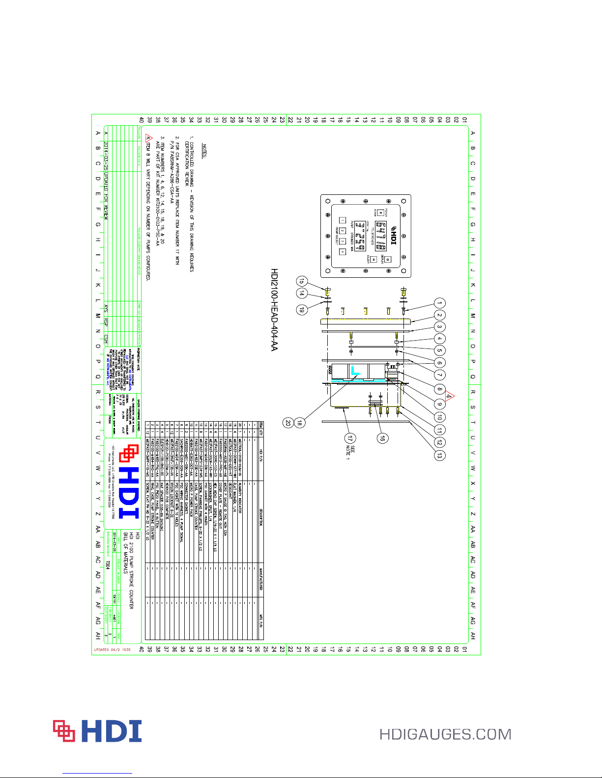
Section 7 – Technical Overview
7.A General Layout Overview
14
Page 15
Pump Stroke Counter
User’s Manual – 2100, Rev D | Aug 2014
7.B Sensor Illustrations
15
Page 16

Pump Stroke Counter
User’s Manual – 2100, Rev D | Aug 2014
7.C Exploded BOM
16
Page 17

Pump Stroke Counter
7.D Common Operational Spare Parts
Item
1 HDIBATTE260DOTAA MICRO P POWER PACK, INCLUDE MSDS CLASS IX
2 FAB2100M485PNLAA PSC PIEZO PANEL 4BTN
3 FAB2100M041GSKAA PSC GASKET W/ 16 HOLES INNER GASKET
4 KIT21000103HRW PSC HARDWARE KIT: DESI PACK, COROSION
5 HDI012D-PUMP-PCB-KT HDI 012 PSC PROCESSOR BOARD ASSY W/
6 HDI012DPSC0COMPL HDI 012 PSC PROCESSOR BOARD ASSY
7 HDI-002STUFBRDAA HDI 002 PSC DEBOUNCE BOARD ASSY
8 HDI2100MICROKITAA MICROSWITCH SENSOR PUMP REPLACEMENT
9 ELESWTH0101CNTPS CONTACT SWITCH – PUMP STROKES
10 ELESWTH0102LVRCN CONTACT SWITCH LEVER (WAND)
11 HDI2100PROXKITAD PROXIMITY SENSOR KIT W/ 2’ PIGTAIL CABLE W/
12 FAB7103M513MGTAA PSC PROXIMITY MAGNET ASSY
13 HDI2100PROXKIT50 PROXIMITY SENSOR KIT W/ PICK UP MAGNET W/
14 ELECONN01133PNTR CONNECTOR 3 PIN TERMINATOR
15 ELECONN01564PNTR CONNECTOR 4 PIN TERMINATOR
16 ELECONN01055PNTR CONNECTOR 5 PIN TERMINATOR
17 21141000000000AA 1 PSC CONTROL HEAD (LCD)
18 21142000000000AA 2 PSC CONTROL HEAD (LCD)
19 21143000000000AA 3 PSC CONTROL HEAD (LCD)
20 21144000000000AA 4 PSC CONTROL HEAD (LCD)
HDI Part # Description
UN 3090
BETWEEN CASE AND PIEZO
INHIBITOR, HUMIDITY INDICATOR, AND SCREWS
DEBOUNCE BOARD
KIT W/ CLAMPS AND MOUNTING HARDWARE
CONNECTOR FOR CLIENT TO INSTALL ON
EXISTING CABLE AND PICK UP MAGNET ASSY
(REPLACEMENT KIT ONLY)
2’ PIGTAIL AND 50’ OPEN LEAD CABLE FOR JBOX
TERMINATION (REPLACEMENT KIT NO JBOX - )
User’s Manual – 2100, Rev D | Aug 2014
17
Page 18
Pump Stroke Counter
User’s Manual – 2100, Rev D | Aug 2014
7.E Proximity Mounting Brackets
18
Page 19

Pump Stroke Counter
User’s Manual – 2100, Rev D | Aug 2014
7.F Proximity Sample Installation Details
SUBJECT: Modify Inspection Plate
DATE: May 4, 2011
This memo is to cover the basic step by step instructions on modifying the Wirth 2200
Series Mud Pumps to install the HDI Proximity Sensors for proper installation whether
interfacing directly with the HDI 2100 Pump Stroke Counter or our HDI V9000 Virtual
Control System.
Per the supplied drawing from the Aker manufacturing plant in Germany, marked Appendix
A, you will need a two (2) man team to complete the basic work. Please review both
Appendix A and B so you can become familiar to the additional reference documents.
You will need to have the following supplies with you to avoid any unexpected delays:
1. Plastic (approx. 2mm thick) to cover the inspection plate while the inspection is
removed and modifications are being completed to prevent debris from entering
the Mud Pump. See attached picture showing the inspection plate removed.
2. Tape – to secure the plastic to the mud pump
3. Torque Wrench suitable to the specified tolerances for the mud pump
4. Socket / Wrench Set to remove the inspection plate bolts approx. ¾”, see Aker
team or manual for actual sizes.
5. HDI Sensor kits – specific bracket for pump model and manufacturer (2200 is the
M368)
6. Tape Measure
7. Drill / Tap for ¾-10
Step 1
First is to loosen all the bolts on the inspection plate after ensuring you have the
correct materials.
Step 2
Remove the inspection plate and put to the side for measuring for modification using
Appendix A. Give to the appropriate personnel to make the necessary modifications
ensuring that you noted top and bottom references.
Step 3
Depending on the location of the piston when the pump was stopped you may be
able to install the M368 bracket without any additional work. Remove the (2) bolts in order
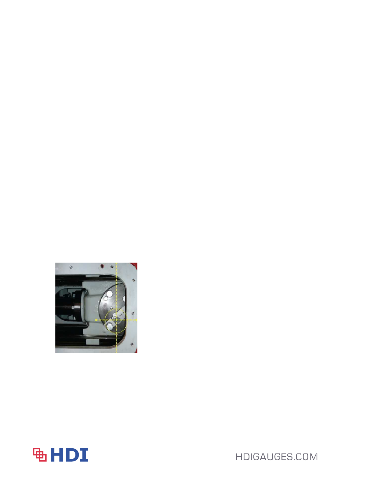
to install the bracket as shown in Appendix B. Install Magnet as noted in the hole placement
on Appendix B and secure the bracket to the piston. Using the manufacturing
specifications, please follow their procedure to Torque the bolts and suggest that they
oversee this process.
19
Page 20
Pump Stroke Counter
User’s Manual – 2100, Rev D | Aug 2014
Note: If the piston can not be accessed, you may have to remove the secondary cover to
manually move the piston forward so you can complete the bracket installation.
Step 4
Prior to installing the HDI Proximity All thread stem (stainless threaded rod) into the
inspection plate, you will need to measure the internal clearance from the magnet to the
outer edge of the pump frame. You will then proceed to thread the stem into the inspection
plate and ensure that you have a maximum ¾” gap between the magnet and all thread.
This measurement needs to be verified to ensure they do not collide inside once the pump is
re-assembled. Once you are certain the measurements are correct, install the washers and
nuts on the stem so the pump vibration does not cause the stem to become loose and create
potential damage.
Step 5
Install the Inspection plate back on to the pump and route the cable lead that is
attached to the stem to the appropriate designated jbox location for termination. The
configuration provided for this project is a Dual pick up sensor with a set on Black / White,
the secondary signals on Red / Green.
Step 6
Repeat above steps until all the pumps are completed.
Sample Wirth 2200 Installation of Proximity Sensor w/ bracket
20
Page 21

Pump Stroke Counter
User’s Manual – 2100, Rev D | Aug 2014
Section 8 – Warranty
HDI Instruments, LLC. (HDI) warrants this product for a period of one year from the date of
shipment. HDI’s manufactured products to the extent that HDI will replace those parts having
defects in material or workmanship when used for the purpose or specification HDI recommends
for Normal Oilfield Usage. For the purpose of this Warranty, Normal Oilfield Usage shall be
defined as normal, oilfield monitoring applications.
HDI shall not honor the Warranty if any evidence of tampering, misuse or intrusion is indicated
except by an HDI authorized technician or agent.
HDI will replace or repair, as it deems necessary, any products covered by this warranty, after
HDI's examination discloses to its satisfaction, that in fact the products are defective and an
adjustment is required. If an adjustment is required, the amount of the adjustment is the net
sales price of the defective product. No allowances shall be made for labor or expenses of
repairing defective products or damage resulting from same. All products accepted under the
provisions of this warranty shall be shipped prepaid to HDI and returned to the customer prepaid
by HDI. This is to include all applicable custom clearance fees, etc. for inbound international
shipments. All products not accepted under the provisions of this warranty shall be shipped
prepaid to HDI and returned freight collect.
HDI shall not be responsible for repair or replacement of products, resulting from improper
handling, storage, installation, misuse, negligence, or use in a manner contrary to the
recommendations of HDI.
HDI warrants only the products that it sells of Other Manufacturers to the extent of their
warranties. All warranty claims shall be made in writing to the nearest HDI office or authorized
factory representative. HDI makes no other warranty of any kind, expressed or implied, and all
implied warranties of merchantability or fitness for a particular purpose which exceed HDI's
afore-stated obligation are hereby disclaimed by HDI and excluded from this warranty.
This Warranty is non transferable and HDI shall not be liable for any damage, injury, loss to
property or persons resulting from the use of any HDI's products or equipment whether such
damage, injury or loss results from, or is caused by: manner of use, defects in materials or
workmanship or otherwise.
21
Page 22
Pump Stroke Counter
User’s Manual – 2100, Rev D | Aug 2014
Appendix
Drilling Instrumentation:
HDI 2100 Mud Pump Stroke Counter
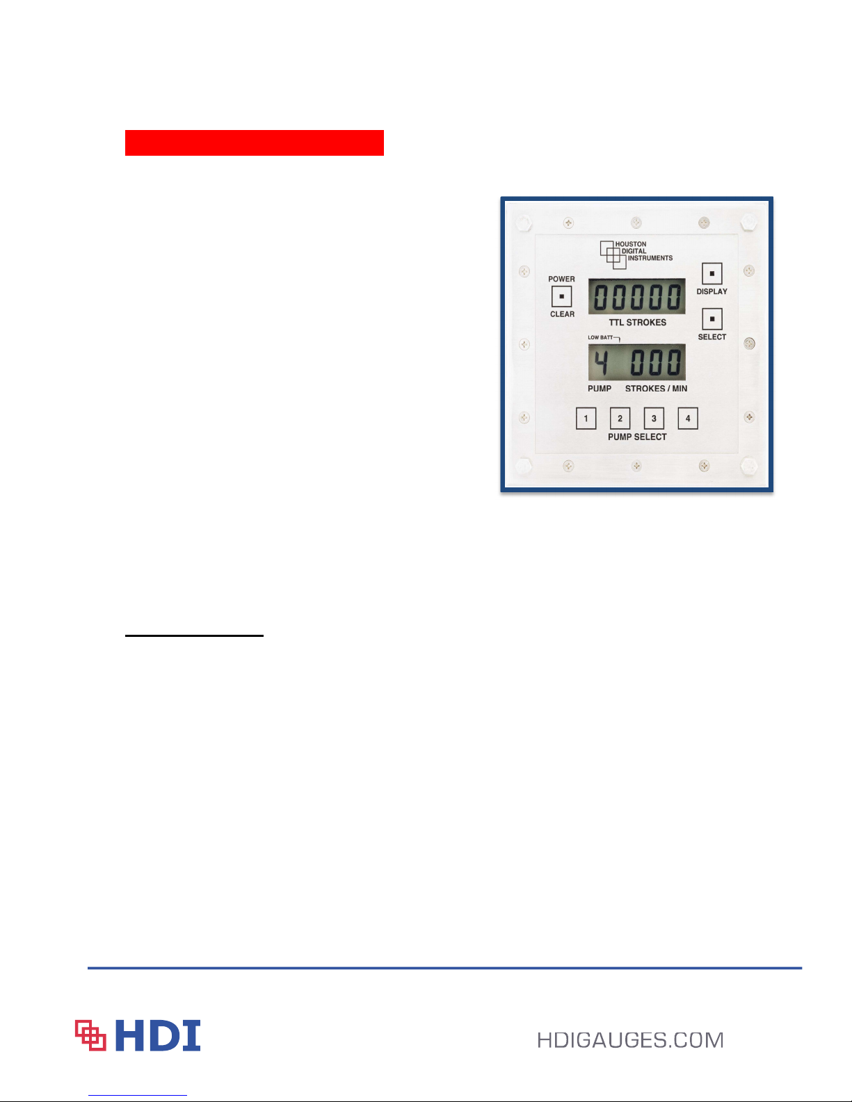
The HDI 2100 monitors and displays the total accumulated
mud pump strokes and the stroke rate of up to 4 individual
mud pumps simultaneously. The stroke rate for each mud
pump can be individually selected for display and is
updated every second. The HDI Battery Pack is designed
to operate continuously 24 / 7 for approximately 18
months. No calibration is required. The quartz crystal
oscillator provides high precision counts with no drift. The
Stroke Counter is designed to be intrinsically safe and is
rated by CSA International for use in Class I, Groups A, B,
C, and D hazardous locations. The stainless steel case is
completely sealed and features stainless steel piezo switches for long life. Labels are engraved permanently
on the front panel. The entire package is constructed to operate in harsh environments and high vibration
conditions encountered for both land and offshore drilling. ATEX certification is available upon request.
Specifications:
Dimensions: 8
Weight:
Case Material:
Front Panel Controls: Power/Clear, Display, Select, Pump Select 1-4
Stroke Rate Range: 11 to 300 Strokes Per Minute SPM
"X8"X4" LXWXD (20.3X20.3X10.2 cm)
5 Lbs. (2.27 Kgs)
Stainless steel
Total Accumulated Strokes: 65,535 strokes
Battery:
Battery Life:
Intrinsically Safe sealed HDI Power Pack
1.7 years continuous operation
External Power: Optional + 12 or + 24 vdc
Low Battery Indicator:
Display:
Time Base:
Pump Switch:
Maximum Cable Length: To be confirmed
Operating & Storage Temp: -40 to
LCD bar above selected pump number
Liquid crystal display of total strokes & selected pump SPM
Quartz crystal oscillator
Micro-switch or passive proximity sensor
100°C
22
Page 23

ISO 9001:2008
Office Phone - 713.688.8555
After Hours Support - 713.819.6103
4130 Directors Row Copyright 2014
Houston, TX 77092 Revision D | August 2014
Effective June 2014
 Loading...