

Page 1

hdg-bavaria.com
HDG K10/15/21/26/33
Operating manual
Page 2

Page 3

Operating manual HDG K10 - 33 - Content
3
Content
1 Notes on this manual . . . . . . . . . . . . . . . . . . . . . . . . . . . . . . . . . . . . . . . . . . . . . . . . . . . . . . . .5
1.1 Introduction. . . . . . . . . . . . . . . . . . . . . . . . . . . . . . . . . . . . . . . . . . . . . . . . . . . . . . . . . . . . . . . . .5
1.2 Glossary. . . . . . . . . . . . . . . . . . . . . . . . . . . . . . . . . . . . . . . . . . . . . . . . . . . . . . . . . . . . . . . . . . . . .6
2 Safety notes. . . . . . . . . . . . . . . . . . . . . . . . . . . . . . . . . . . . . . . . . . . . . . . . . . . . . . . . . . . . . . . . .7
2.1 Intended use . . . . . . . . . . . . . . . . . . . . . . . . . . . . . . . . . . . . . . . . . . . . . . . . . . . . . . . . . . . . . . . .7
Basic system design principles. . . . . . . . . . . . . . . . . . . . . . . . . . . . . . . . . . . . . . . . . . . . . .7
Basic principles for the content of the operating manual . . . . . . . . . . . . . . . . . . . . 7
Proper and improper operation . . . . . . . . . . . . . . . . . . . . . . . . . . . . . . . . . . . . . . . . . . . .7
2.2 Residual risks. . . . . . . . . . . . . . . . . . . . . . . . . . . . . . . . . . . . . . . . . . . . . . . . . . . . . . . . . . . . . . . .8
2.3 Warnings and safety symbols used. . . . . . . . . . . . . . . . . . . . . . . . . . . . . . . . . . . . . . . . . . .9
2.4 Safety instructions for the pellet storage room . . . . . . . . . . . . . . . . . . . . . . . . . . . . . .11
2.5 Duty of information . . . . . . . . . . . . . . . . . . . . . . . . . . . . . . . . . . . . . . . . . . . . . . . . . . . . . . . .11
3 Mode of operation . . . . . . . . . . . . . . . . . . . . . . . . . . . . . . . . . . . . . . . . . . . . . . . . . . . . . . . . .12
3.1 Overview. . . . . . . . . . . . . . . . . . . . . . . . . . . . . . . . . . . . . . . . . . . . . . . . . . . . . . . . . . . . . . . . . . .12
Cross section of HDG K10 - 33 . . . . . . . . . . . . . . . . . . . . . . . . . . . . . . . . . . . . . . . . . . . . .12
3.2 Functional description. . . . . . . . . . . . . . . . . . . . . . . . . . . . . . . . . . . . . . . . . . . . . . . . . . . . . .13
Combustion process . . . . . . . . . . . . . . . . . . . . . . . . . . . . . . . . . . . . . . . . . . . . . . . . . . . . . .13
Boiler and weather-compensated heating control HDG Control . . . . . . . . . . . .14
Delivery system . . . . . . . . . . . . . . . . . . . . . . . . . . . . . . . . . . . . . . . . . . . . . . . . . . . . . . . . . . .14
Pellet suction system. . . . . . . . . . . . . . . . . . . . . . . . . . . . . . . . . . . . . . . . . . . . . . . . . . . . . .15
Reservoir . . . . . . . . . . . . . . . . . . . . . . . . . . . . . . . . . . . . . . . . . . . . . . . . . . . . . . . . . . . . . . . . .15
3.3 Technical data . . . . . . . . . . . . . . . . . . . . . . . . . . . . . . . . . . . . . . . . . . . . . . . . . . . . . . . . . . . . .16
3.4 Fuel quality requirements. . . . . . . . . . . . . . . . . . . . . . . . . . . . . . . . . . . . . . . . . . . . . . . . . . .17
Recommended fuel . . . . . . . . . . . . . . . . . . . . . . . . . . . . . . . . . . . . . . . . . . . . . . . . . . . . . . .17
4 Planning and installation . . . . . . . . . . . . . . . . . . . . . . . . . . . . . . . . . . . . . . . . . . . . . . . . . . .18
4.1 Planning the heating system. . . . . . . . . . . . . . . . . . . . . . . . . . . . . . . . . . . . . . . . . . . . . . . .18
Required room sizes and minimum clearances . . . . . . . . . . . . . . . . . . . . . . . . . . . . .18
Dimensions and connections . . . . . . . . . . . . . . . . . . . . . . . . . . . . . . . . . . . . . . . . . . . . .19
Furnace room. . . . . . . . . . . . . . . . . . . . . . . . . . . . . . . . . . . . . . . . . . . . . . . . . . . . . . . . . . . . .19
4.2 Connections . . . . . . . . . . . . . . . . . . . . . . . . . . . . . . . . . . . . . . . . . . . . . . . . . . . . . . . . . . . . . . .20
Chimney . . . . . . . . . . . . . . . . . . . . . . . . . . . . . . . . . . . . . . . . . . . . . . . . . . . . . . . . . . . . . . . . .20
Electrical system . . . . . . . . . . . . . . . . . . . . . . . . . . . . . . . . . . . . . . . . . . . . . . . . . . . . . . . . . .22
Water . . . . . . . . . . . . . . . . . . . . . . . . . . . . . . . . . . . . . . . . . . . . . . . . . . . . . . . . . . . . . . . . . . . .22
4.3 Scope of delivery . . . . . . . . . . . . . . . . . . . . . . . . . . . . . . . . . . . . . . . . . . . . . . . . . . . . . . . . . . .24
4.4 Installing the heating system . . . . . . . . . . . . . . . . . . . . . . . . . . . . . . . . . . . . . . . . . . . . . . .25
Supply. . . . . . . . . . . . . . . . . . . . . . . . . . . . . . . . . . . . . . . . . . . . . . . . . . . . . . . . . . . . . . . . . . . .26
Removing the transport pallet. . . . . . . . . . . . . . . . . . . . . . . . . . . . . . . . . . . . . . . . . . . . .27
Installing the boiler . . . . . . . . . . . . . . . . . . . . . . . . . . . . . . . . . . . . . . . . . . . . . . . . . . . . . . .28
Fitting the filling and drain cock . . . . . . . . . . . . . . . . . . . . . . . . . . . . . . . . . . . . . . . . . . .29
Converting the flue pipe connection . . . . . . . . . . . . . . . . . . . . . . . . . . . . . . . . . . . . . .29
Page 4

Operating manual HDG K10 - 33 - Content
4
Installing the reservoir . . . . . . . . . . . . . . . . . . . . . . . . . . . . . . . . . . . . . . . . . . . . . . . . . . . 31
Fitting the cladding . . . . . . . . . . . . . . . . . . . . . . . . . . . . . . . . . . . . . . . . . . . . . . . . . . . . . . 33
Installing the ash container. . . . . . . . . . . . . . . . . . . . . . . . . . . . . . . . . . . . . . . . . . . . . . . 37
Mounting the expansion modules . . . . . . . . . . . . . . . . . . . . . . . . . . . . . . . . . . . . . . . 37
Connecting the suction and return hoses . . . . . . . . . . . . . . . . . . . . . . . . . . . . . . . . . 39
4.5 Connecting the chimney. . . . . . . . . . . . . . . . . . . . . . . . . . . . . . . . . . . . . . . . . . . . . . . . . . . 39
4.6 Electrical system. . . . . . . . . . . . . . . . . . . . . . . . . . . . . . . . . . . . . . . . . . . . . . . . . . . . . . . . . . . 39
4.7 Water . . . . . . . . . . . . . . . . . . . . . . . . . . . . . . . . . . . . . . . . . . . . . . . . . . . . . . . . . . . . . . . . . . . . . 40
5 Commissioning the system . . . . . . . . . . . . . . . . . . . . . . . . . . . . . . . . . . . . . . . . . . . . . . . . 41
5.1 Requirements . . . . . . . . . . . . . . . . . . . . . . . . . . . . . . . . . . . . . . . . . . . . . . . . . . . . . . . . . . . . . 41
5.2 Procedure . . . . . . . . . . . . . . . . . . . . . . . . . . . . . . . . . . . . . . . . . . . . . . . . . . . . . . . . . . . . . . . . . 42
Setting the fuel quantity . . . . . . . . . . . . . . . . . . . . . . . . . . . . . . . . . . . . . . . . . . . . . . . . . 42
Perform actuator test . . . . . . . . . . . . . . . . . . . . . . . . . . . . . . . . . . . . . . . . . . . . . . . . . . . . 42
Adapting parameters . . . . . . . . . . . . . . . . . . . . . . . . . . . . . . . . . . . . . . . . . . . . . . . . . . . . 42
6 Using the heating system . . . . . . . . . . . . . . . . . . . . . . . . . . . . . . . . . . . . . . . . . . . . . . . . . . 43
6.1 Control unit for HDG Control. . . . . . . . . . . . . . . . . . . . . . . . . . . . . . . . . . . . . . . . . . . . . . . 43
6.2 Filling the pellet storage room . . . . . . . . . . . . . . . . . . . . . . . . . . . . . . . . . . . . . . . . . . . . . 43
Requirements. . . . . . . . . . . . . . . . . . . . . . . . . . . . . . . . . . . . . . . . . . . . . . . . . . . . . . . . . . . . 43
Procedure . . . . . . . . . . . . . . . . . . . . . . . . . . . . . . . . . . . . . . . . . . . . . . . . . . . . . . . . . . . . . . . 43
6.3 Filling the reservoir . . . . . . . . . . . . . . . . . . . . . . . . . . . . . . . . . . . . . . . . . . . . . . . . . . . . . . . . 44
6.4 Performing a chimney sweep measurement. . . . . . . . . . . . . . . . . . . . . . . . . . . . . . . . 44
6.5 Switching off the heating system for repair work . . . . . . . . . . . . . . . . . . . . . . . . . . . 45
7 Cleaning and servicing the heating system . . . . . . . . . . . . . . . . . . . . . . . . . . . . . . . . . 46
7.1 Cleaning and servicing schedule . . . . . . . . . . . . . . . . . . . . . . . . . . . . . . . . . . . . . . . . . . . 46
7.2 Procedure . . . . . . . . . . . . . . . . . . . . . . . . . . . . . . . . . . . . . . . . . . . . . . . . . . . . . . . . . . . . . . . . . 47
Generally applicable safety instructions. . . . . . . . . . . . . . . . . . . . . . . . . . . . . . . . . . . 47
Cleaning tools . . . . . . . . . . . . . . . . . . . . . . . . . . . . . . . . . . . . . . . . . . . . . . . . . . . . . . . . . . . 48
Emptying the ash container . . . . . . . . . . . . . . . . . . . . . . . . . . . . . . . . . . . . . . . . . . . . . . 48
Cleaning the combustion chamber and burner pot . . . . . . . . . . . . . . . . . . . . . . . 49
Cleaning the flue gas fan and cleaning shaft . . . . . . . . . . . . . . . . . . . . . . . . . . . . . . 52
Cleaning the flue gas pipe. . . . . . . . . . . . . . . . . . . . . . . . . . . . . . . . . . . . . . . . . . . . . . . . 53
Check the fill level of the water tank . . . . . . . . . . . . . . . . . . . . . . . . . . . . . . . . . . . . . . 53
Checking and cleaning the reservoir and flap of the delivery unit . . . . . . . . . . 54
Cleaning the pellet storage room . . . . . . . . . . . . . . . . . . . . . . . . . . . . . . . . . . . . . . . . . 56
8 Notes on dismantling and disposal. . . . . . . . . . . . . . . . . . . . . . . . . . . . . . . . . . . . . . . . . 58
8.1 Dismantling . . . . . . . . . . . . . . . . . . . . . . . . . . . . . . . . . . . . . . . . . . . . . . . . . . . . . . . . . . . . . . . 58
8.2 Disposal. . . . . . . . . . . . . . . . . . . . . . . . . . . . . . . . . . . . . . . . . . . . . . . . . . . . . . . . . . . . . . . . . . . 58
9 Declaration of Conformity . . . . . . . . . . . . . . . . . . . . . . . . . . . . . . . . . . . . . . . . . . . . . . . . . 60
10 Index. . . . . . . . . . . . . . . . . . . . . . . . . . . . . . . . . . . . . . . . . . . . . . . . . . . . . . . . . . . . . . . . . . . . . . 61
Page 5

1 Notes on this manual – Introduction
5
1 Notes on this manual
1.1 Introduction
EASY AND SAFE OPERATION This operating manual contains important instructions on the
• HDG K10
• HDG K15
• HDG K21
• HDG K26
• HDG K33
and how to operate it properly and safely. Following these
instructions helps to avoid dangers, prevent repair costs and
downtimes, maintain reliability and extend the life expectancy of the
heating system.
R
EADING THE OPERATING
MANUAL
This operating manual must be read and observed by everyone who
operates or works on the HDG K10 - 33.
T
ECHNICAL CHANGES We continuously develop and improve our boilers. The information
in this edition was correct at the time of going to press.
All details in these instructions on standards, regulations and
worksheets should be checked before use and should be compared
with the regulations applying locally at the site where the system is
installed.
We reserve the right to make changes which may then differ from the
technical details and illustrations in this operating manual.
C
OPYRIGHT Written permission is required from HDG Bavaria GmbH for
reprinting, storage in a data-processing system or transmission by
electronic, mechanical, photographic or any other means, and for
copies or translations of this publication, in whole or in part.
G
UARANTEE The terms and conditions of the guarantee of your boiler can be
found in the enclosed information sheet.
S
YMBOLS USED In this operating manual, the following designations and symbols are
used for particularly important information:
1. Instructions to the operator
✓ Result of the action described
✎ Cross reference for more explanation
• List
–List
Page 6

1 Notes on this manual – Glossary
6
1.2 Glossary
Term Explanation
Actuator This is a component which carries out a certain function in the
heating system e.g. the worm feed stoking unit.
Automatic cleaning At intervals, automatically cleans the surface of the heat
exchangers.
Delivery system Pellet transport system in the pellet storage room.
Display Display of the boiler control unit.
Extinguishing device Extinguishes the contents of the reservoir if the temperature of the
contents exceeds 90°C.
HDG Control Boiler and heating system controller.
HDG K10 - 33 Heating system for burning wood pellets.
Heating system Comprised of boiler and corresponding accessories.
Pellet suction system Pellet transport system which connects the reservoir with the
delivery system.
Reservoir A container which supplies pellets to be burnt in the boiler via the
conveying auger.
Sensor Records certain parameters (temperature, fill level) and forwards
them to the control for analysis.
Wood pellets Binder-free pellets made of pressed, untreated wood.
Table 1/1 - Glossary
Page 7

2 Safety notes – Intended use
7
2 Safety notes
2.1 Intended use
BASIC SYSTEM DESIGN PRINCIPLES
BASIC PRINCIPLES The heating system was built using state-of-the-art technology and
conforms to recognised safety regulations. Nevertheless, there is still
a risk of injury or death to users or bystanders, and of adverse effects
upon the heating system or upon other material goods.
Have your specialist heating company provide you with a detailed
explanation of the operation of the heating system.
U
SING THE HEATING SYSTEM Only use the heating system when it is in perfect condition. Use it
properly, as intended, be aware of safety and hazards, and observe
the Operating manual. Have any faults which could impair safety
fixed immediately.
This device can be used by children over 8 years old and people with
reduced physical, sensory or mental capabilities or a lack of
experience and knowledge, provided they are supervised or have
been instructed on the safe use of the device and understand the
resulting risks. Children may not play with the device. Cleaning and
user maintenance must not be carried out by children without
supervision.
BASIC PRINCIPLES FOR THE CONTENT OF THE OPERATING MANUAL
SCOPE The content of this operating manual is intended exclusively for the
planning, installation and operation of the HDG K10 - 33 heating
systems. The further implementation of applicable standards and
guidelines, for example regarding installation of the heating system
(pipework, etc.), is not part of this operating manual. HDG Bavaria
does not assume any liability for this.
PROPER AND IMPROPER OPERATION
PURPOSE OF THE HEATING
SYSTEM
The heating system HDG K10 - 33 was designed to burn wood pellets
in hot water heating systems.
Any other application is considered improper use. The manufacturer
will accept no liability for any damage resulting from improper use.
The operator bears sole responsibility in such cases.
Proper use includes adherence to the installation, operation and
maintenance requirements specified by the manufacturer.
Page 8
2 Safety notes – Residual risks
8
Modification of the specified operating values will affect the heating
system’s control programme and could lead to malfunctions. Only
trained maintenance and operating personnel may undertake
modifications to the operating values.
2.2 Residual risks
Despite all precautions, the following residual risks remain:
For more information on fuel, see chapter “3 Mode of operation”,
section “3.4 Fuel quality requirements”.
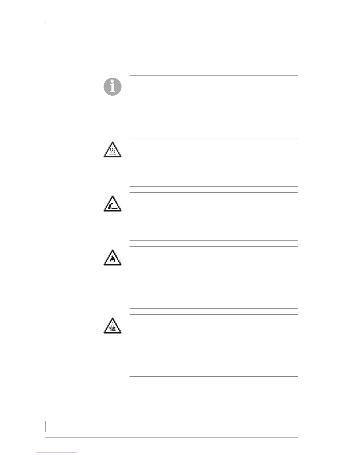
Caution!
Hot surfaces
Contact with the hot surfaces of the boiler can lead to burns.
Wait until the boiler has cooled down before touching non-
insulated components.
Danger!
Danger of asphyxiation due to lack of oxygen
If the boiler is in operation, carbon monoxide can be emitted
through the open doors and lids.
Do not leave the doors and lids open any longer than necessary.
Warning!
Danger of fire
Opening doors and lids to hot combustion residues during
operation can pose the danger of fires.
Keep the openings closed during operation, and when performing
cleaning work, allow the combustion residues to cool down before
you place them in a fireproof container.
Warning!
Danger from suspended loads
The boiler weighs over 300 kg. If the boiler is dropped during
transport, persons can be seriously injured and the boiler can be
damaged.
Make sure that you use appropriate lifting gear when placing the
boiler.
Page 9
2 Safety notes – Warnings and safety symbols used
9
2.3 Warnings and safety symbols used
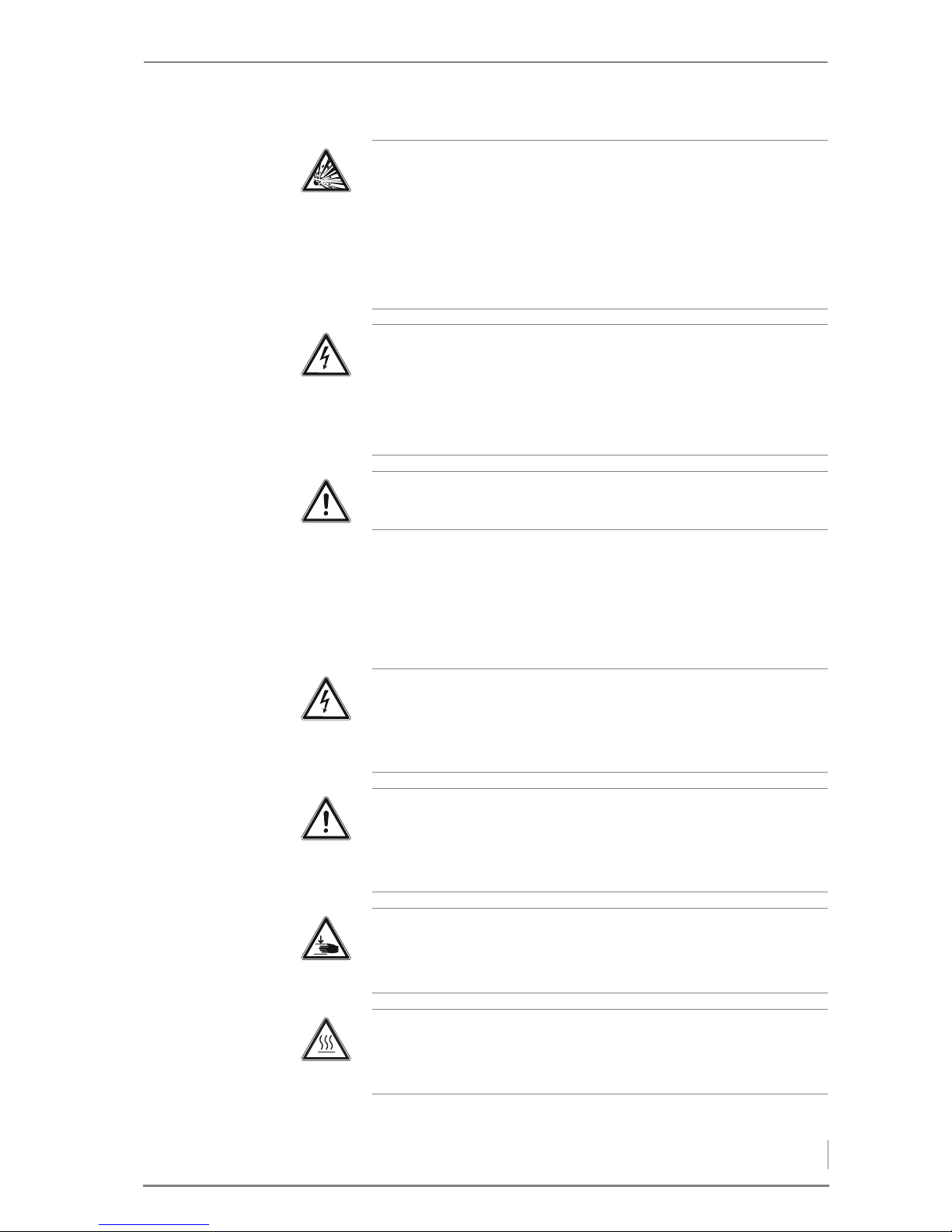
The following warnings and safety symbols are used in this
Operating manual:
Danger!
Danger of explosion due to carbon monoxide
Filling the burner pot with pellets manually may result in too much
fuel in the burner pot. Consequently the pellets will not be
optimally ignited and too much low temperature carbonisation gas
may result which can lead to an explosion.
Do not fill the burner pot manually.
Danger!
Dangerous electrical current or voltage
The circuit boards and other electrical components carry current.
Have work on electrical components performed only by a qualified
electrician and turn the main switch off.
Warning!
The boiler is under pressure.
Danger!
Dangerous electrical current or voltage
Work in areas marked with this symbol may only be performed by a
qualified electrician.
Warning!
Hazardous area
Working in areas marked with this symbol can lead to serious
injuries or to extensive material damage.
Warning!
Hand injuries can occur
Working in areas marked with this symbol can lead to hand injuries.
Caution!
Hot surfaces
Working in areas marked with this symbol can lead to burns.
Page 10
2 Safety notes – Warnings and safety symbols used
10
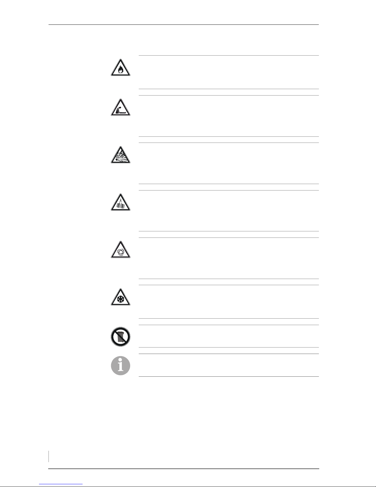
Warning!
Danger of fire
Working in areas marked with this symbol can lead to a fire.
Danger!
Danger of asphyxiation due to lack of oxygen
When working in areas marked with this symbol, there is a danger
of asphyxiation due to high concentrations of carbon monoxide.
Caution!
Danger of explosion
When working in areas marked with this symbol, there is a danger
of explosion due to high concentrations of carbon monoxide.
Warning!
Suspended loads
When working in areas marked with this symbol, there is a danger
of falling objects.
Caution!
Automatic start-up
Working in areas marked with this symbol can lead to injuries due
to automatic start-up.
Important!
Frost danger
Only install the heating system in a frost-proof room.
Instructions regarding disposal
Additional information for the operator
Page 11

2 Safety notes – Safety instructions for the pellet storage room
11
2.4 Safety instructions for the pellet storage
room
After the storage room is filled, odourless carbon monoxide may
form and a lack of oxygen may arise. Therefore, in the first 6 weeks
after filling the storage room, it is prohibited to enter the storage
room, and only trained personnel may do so.
For pellet storage rooms, a special sticker (issued by the German
Association of wood and pellet fuels - DEPV) must be attached to the
access hatch to the fuel storage room.
It lists the following instructions.
• Access prohibited to unauthorised persons, keep children away!
• Smoking, flames and other sources of ignition prohibited.
• Turn the pellet boiler off for at least 1 hour before filling.
• Ensure adequate ventilation before entering.
• Beware of a risk of injury from moving components.
• Make sure filling is carried out properly.
2.5 Duty of information
READING THE OPERATING
MANUAL
Any person performing tasks on this system must read the Operating
manual prior to beginning work, particularly the chapter “2 Safety
notes”.
This is especially important for persons who only occasionally work
on the heating system, for example when cleaning or servicing it.
The Operating manual must always be kept readily accessible at the
place where heating system is installed.
In addition, observe the VDI guideline 3464 “Storage of wood
pellets at the consumer”.
Page 12
3 Mode of operation – Overview
12
3 Mode of operation
3.1 Overview
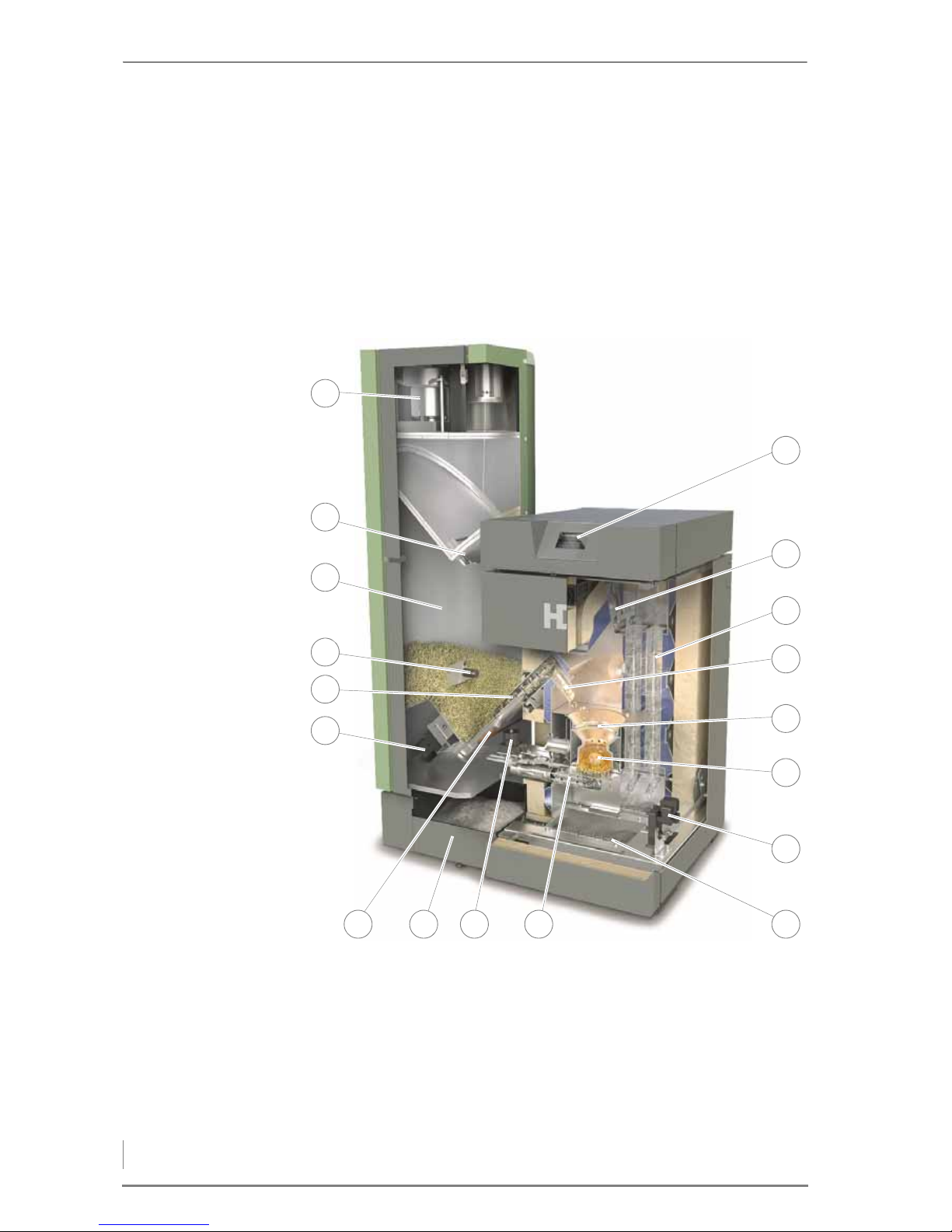
CROSS SECTION OF HDG K10 - 33
1 Vacuum fan
2 Flap of the delivery unit
3 Reservoir
4 Reservoir level indicator
5 Conveyor auger
6 Drive motor of stoker auger
7 Sensor for auger pipe safety thermostat
Figure 3/1 - Cross section of HDG K10 - 33
8
1
6
4
7 11
13
14
16
18
10
12
3
5
2
17
15
9
Page 13

3 Mode of operation – Functional description
13
8Ash container
9 Combustion grate drive motor
10 Ignition element
11 Ash compartment
12 Ash removal / cleaning system drive motor
13 Primary air pin
14 Burner pot
15 Drop chute
16 Heat exchanger surfaces incl. turbulators
17 Combustion chamber temperature sensor
18 Control unit HDG Control Touch
3.2 Functional description
COMBUSTION PROCESS
In boiler HDG K10 - 33, the pellets are automatically transported from
the fuel storage room to the reservoir using the delivery system with
the assistance of the pellet suction system. The feeding system
conveys the pellets to the burner pot of the boiler.
The automatic pellet suction system does not need to be fitted. In
this case the reservoir will be filled manually.
The combustion process starts with a preliminary flushing. The flue
gas fan and the combustion chamber of the boiler is flushed with
fresh air. The next step is the ignition phase. The supplied pellets are
automatically ignited with a heating element. In the subsequent
flame stabilisation phase, even combustion is established.
The system then changes to modulation mode. In this mode,
combustion is carried out according to the required output.
The boiler HDG K10 - 33 is equipped as standard with an automatic
heat exchanger cleaning system. This ensures a consistently high
heat transfer and consequently a high level of efficiency.
If the extracted power falls below the minimum nominal thermal
power or there is no heating request, the boiler goes into burn-out
mode. The flue gas fan continues running until the burner pot has
cooled down.
To prevent the grating from slagging up and to ensure ash removal
occurs, the grate plate is moved at intervals. The automatic ash
removal system transports the accumulated fly and combustion ash
to the external ash container.
The air necessary for combustion is supplied as required via a speedcontrolled flue gas fan.
Sensors are used to:
– Continuously monitor the firing
Page 14

3 Mode of operation – Functional description
14
– Adapt the boiler output to the heat requirements
– Minimise emissions
– To optimise boiler efficiency
BOILER AND WEATHER-COMPENSATED HEATING CONTROL HDG
CONTROL
BOILER CONTROL UNIT The boiler control unit of the pellet boiler HDG K10 - 33 is the
electronic hub. It consists of the ready-to-use control panel and
control unit on the top right side of the boiler. Using the control unit,
you can regulate the boiler and call up information on the current
process.
If the heating circuits issue a request for more heat, the pellet system
automatically switches to the flushing operating mode and the
combustion process begins.
Once the desired boiler temperature has been reached, i.e. the need
for heat has been met, the heating system changes to Burn out
mode and subsequently to the operating status Standby.
H
EATING CIRCUIT CONTROL The HDG Control controls the entire energy management of the
heating system including the following, depending on the version:
• Accumulator management
• Weather-compensated heating circuits
• Domestic hot water heating
• Control of the second boiler
• Transfer of heat into the district heating grid
• Solar system for hot water and support of the heating system
✎ For a description of the HDG Control boiler and weather-compen-
sated heating control, refer to the “HDG Control” operating
manual.
DELIVERY SYSTEM
The delivery system is in the pellet storage room. Various delivery
system options are available.
• Suction probes: The pellets are drawn up through 8 suction
probes in the fuel storage room.
• Auger: Via an auger, the pellets on the sloping floor are
transported to the transfer station.
• Pellet mole: The pellet mole moves freely in the fuel storage room.
• Pellet fabric silo: External pellet storage made from polyester.
The delivery system is controlled by the control system HDG Control.
Page 15

3 Mode of operation – Functional description
15
PELLET SUCTION SYSTEM
The pellet suction system links the delivery system with the reservoir
of the HDG K10 - 33 boiler. This process is monitored by sensors and,
using the boiler control system, can be limited to various times of
day.
RESERVOIR
Various versions are available:
Reservoir
Automatic
Reservoir
Manual, small
(Day container)
Reservoir
Manual, large
(Week container)
Filling Automatic (pellet
suction system)
By hand By hand
Volume 107 kg 107 kg 200 kg
Table 3/1 - Reservoir
Page 16
3 Mode of operation – Technical data
16
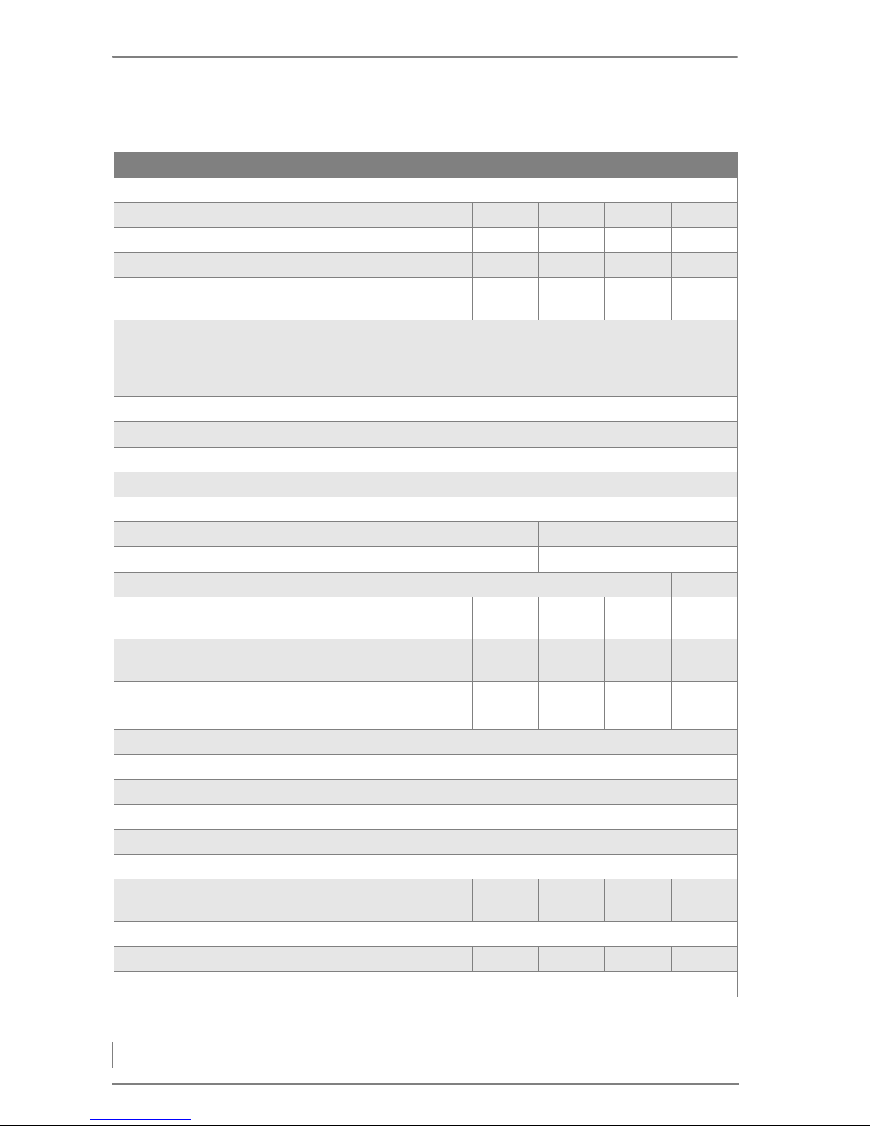
3.3 Technical data
*Maximum operating temperatures of up to 110 °C can also briefly occur.
Type of boiler HDG K10 HDG K15 HDG K21 HDG K26 HDG K33
Performance data (measured according to DIN EN 303-5)
Nominal thermal power 9.9 kW 15 kW 21 kW 25.9 kW 32.5 kW
Minimum thermal power 3.0 kW 4.3 kW 6.3 kW 7.6 kW 9.8 kW
Boiler efficiency at nominal thermal power 94.4 % 93.8 % 93.9 % 93.9 % 94.8 %
Electrical power consumption at nominal
thermal power 28 W 33 W 41 W 48 W 77 W
Electrical connection:
• Voltage
• Frequency
• Back-up fuse
230 V
50 Hz
13 A (slow-blow)
General boiler data
Boiler class 5
Maximum permissible operating pressure 3.0 bar
Maximum supply temperature 85 °C*
Minimum return temperature 20 °C
Water capacity 39 l 47 l
Weight 261 kg 283 kg
Planning data for flue calculation (DIN EN 13384-1)
Flue gas temp. (Tw) at nominal thermal power
Flue gas temp. (Tw) at lowest thermal power
98 °C
78 °C
119 °C
82 °C
127 °C
87 °C
134 °C
90 °C
138 °C
92 °C
Flue gas mass flow, nominal thermal power
Flue gas mass flow, minimum thermal power
0.0058kg/s
0.0025kg/s
0.0085kg/s
0.0034kg/s
0.0118kg/s
0.0044kg/s
0.0146kg/s
0.0049kg/s
0.0180kg/s
0.0060kg/s
CO2 content at nominal thermal power
CO
2
content at minimum thermal power
13.4 %
9.7 %
14.2 %
10.1 %
14.2 %
11.3 %
14.2 %
12.1 %
14.6 %
12.3 %
Flue draught requirement (Pw) 5 Pa
Diameter of flue pipe connection 130 mm
Height at middle of flue gas pipe connection 1050 mm (top) / 750 mm (rear)
Water-side connections
Supply and return connections DN 25, outside thread
Recommended pipe dimensions (minimum) DN 25
Water-side resistance, 10 K
Water-side resistance, 20 K
360 Pa
100 Pa
760 Pa
210 Pa
1430 Pa
390 Pa
2150 Pa
580 Pa
3110 Pa
860 Pa
Other information
Sound pressure level
45.3 dB(A) 45.7 dB(A) 46.1 dB(A) 46.5 dB(A) 47.6 dB(A)
Min. Air inlet cross section 150 cm²
Table 3/2 - Technical data
Page 17
3 Mode of operation – Fuel quality requirements
17
3.4 Fuel quality requirements
Only wood pellets are permissible as fuel for the HDG K10 - 33 boiler.
Wood pellets are pressed into a cylindrical shape. They consist of
untreated shavings and sawdust from the wood processing industry
as well as unprocessed forestry waste. They have a standardised
diameter and length. They are pressed at a very high pressure and
have a very low water content. The energy contained in 2 kg of
pellets corresponds approximately to the energy contained in a litre
of heating oil.
Essential criteria for the definition of the property classes are the
length and diameter, moisture content and ash content of the fuel.
L
ENGTH AND DIAMETER The diameter of the pellets used must be in accordance with D06, i.e.
6 mm +/- 1 mm. The length of the pellets must measure between
3.15 mm and 40 mm. A maximum of 1.0% by weight of the pellets
may be longer than 45 mm.
W
ATER CONTENT The water content must be less than 10% (M10) for property classes
A1, A2 and B.
A
SH CONTENT The ash content of the property class A2 and B is higher than that of
A1 due to the higher proportion of bark, needles and leaves. The
maximum ash content for property class A1 is 0.7% by weight (A0.7),
for property class A2 the maximum ash content is 1.2 % by weight
(A1.2) and for property class B the maximum ash content is 2.0 % by
weight (A2.0). In accordance with the 1st Federal Emission Control
Ordinance, operation with pellets in Germany is limited to property
class A1.
Alternatively pellets with the “ENplus” or “DINplus” certificate are
also suitable as they meet the quality requirements of property class
A1.
RECOMMENDED FUEL
It is important that fuel is used according to HGD fuel specifications
In particular, all fuel requirements concerning size, water content
and ash content must be met..
With regard to the quality standards for pellets, DIN EN ISO 17225-2
“Biogenic solid fuel - fuel specifications and classes - classification of
pellets” applies.
In accordance with this standard, the properties of pellets that can
be used with the HDG K10 - 33 are specified below in more detail.
Pay particular attention to the fuel quality, both when ordering and
at delivery.
Important!
If there is a significant change of fuel, the system must be reset
accordingly and checked for emissions by authorised specialists.
Page 18
4 Planning and installation – Planning the heating system
18
4 Planning and installation
4.1 Planning the heating system
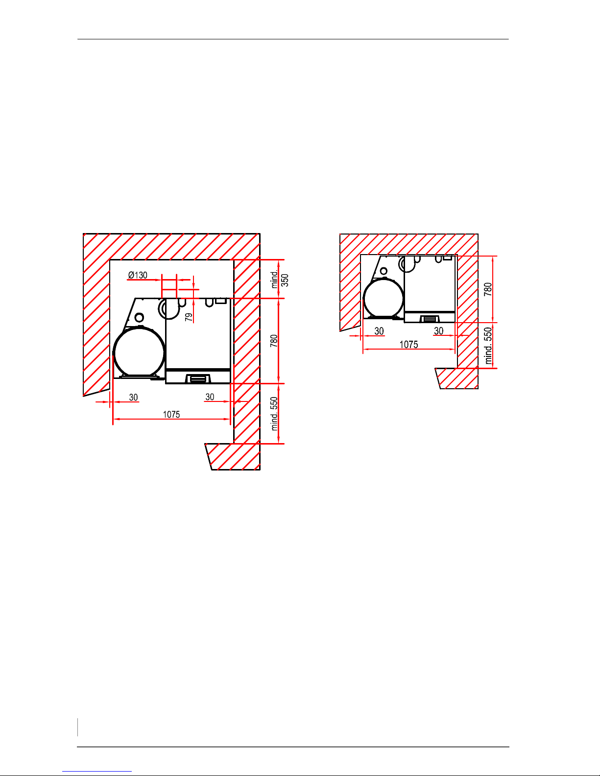
REQUIRED ROOM SIZES AND MINIMUM CLEARANCES
* for HDG K21/26/33. For HDG K10/15 = 710 mm
** with 107 kg reservoir. With 200 kg reservoir = 1425 mm
Minimum room height: 1850 mm
Recommended room height: 2250 mm
Figure 4/1 - Room sizes and minimum clearances in mm
*
**
*
**
Flue pipe behind Flue pipe above
Page 19
4 Planning and installation – Planning the heating system
19
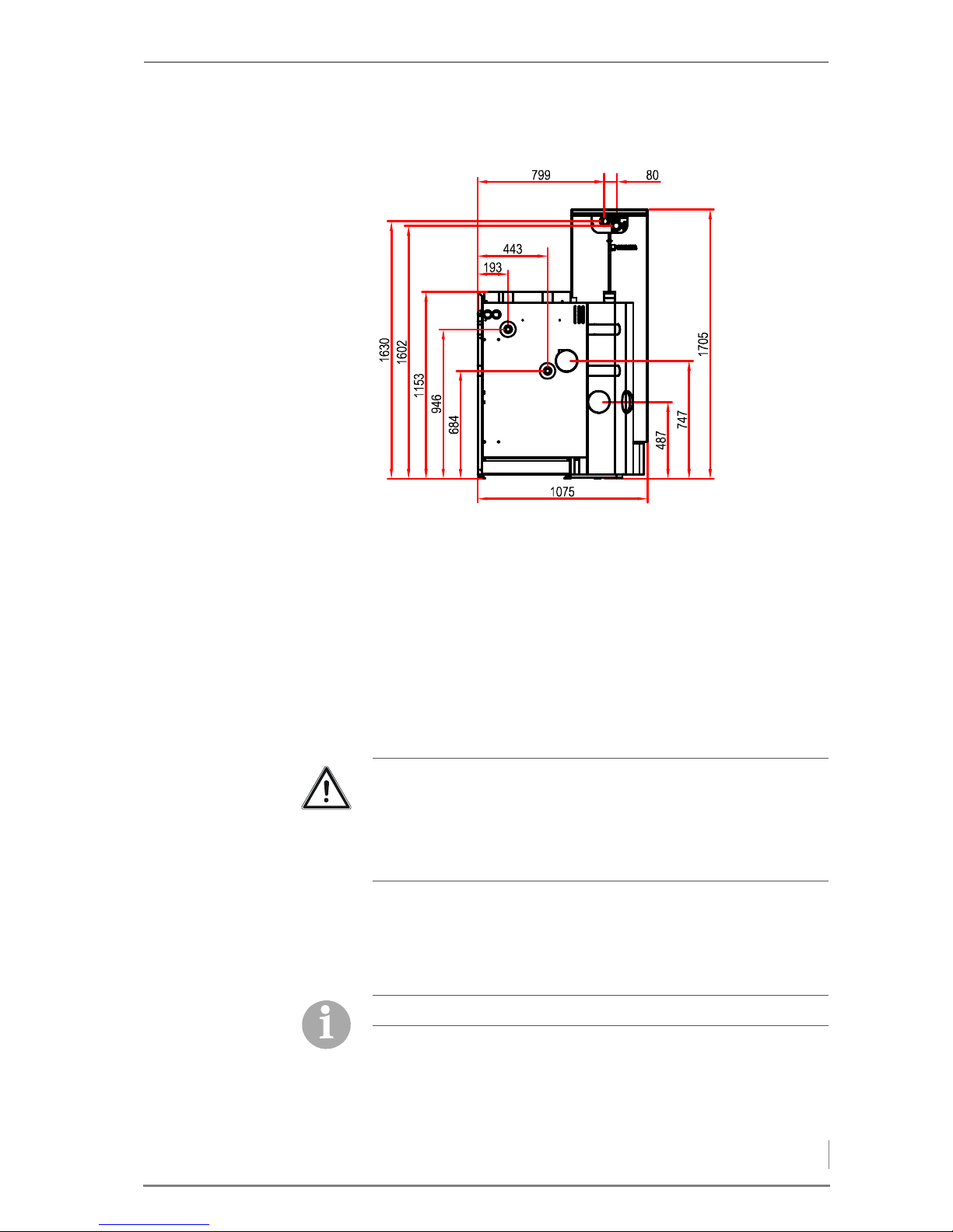
DIMENSIONS AND CONNECTIONS
* with 107 kg reservoir. With 200 kg reservoir = 1470 mm
** with 107 kg reservoir. With 200 kg reservoir = 1425 mm
1 Boiler supply connection (DN 25, outside thread)
2 Boiler return connection (DN 25, outside thread)
FURNACE ROOM
APPLICABLE REGULATIONS Local building regulations always apply. In Germany, individual state
regulations on boilers and furnaces (FeuVO) also apply.
Make sure there is an adequate supply of fresh air to the boiler room
so that there is enough air available for the combustion process and
to protect the operator from the hazards of insufficient oxygen.
I
NSTALLATION A base is not necessary for installation of the heating system. Ensure
alignment on a horizontal plane.
To ensure unhindered operation and maintenance of the heating
system, it is imperative that the heating system is installed in
accordance with the specifications of HDG Bavaria and that the
minimum spacing requirements are observed.
Figure 4/2 - Dimensions (mm) and connections
*
**
1
2
Important!
Building regulations may differ from country to country and state to
state.
For this reason, consult a qualified specialist for the planning and
installation of your boiler room.
Observe the fire safety regulations.
Page 20

4 Planning and installation – Connections
20
Also note that the thresholds in DIN 4109 “Soundproofing in building
construction” may not be exceeded.
More detailed information can be found in the relevant local and
national regulations.
We recommend that objects which are not needed for the operation
or maintenance of the heating system not be stored in the boiler
room.
4.2 Connections
CHIMNEY
The benefits of the HDG K10 - 33 can only be enjoyed if all of the
prerequisites for good combustion are ensured. The heating system
and chimney form a single functional unit and must be adapted to
one another in order to guarantee fault-free and economical
operation.
Since the flue temperature may lie below 100°C when the system is
partially loaded, a chimney/flue is required which meets the
requirements of DIN EN 13384-1: 2003-03 “Thermal and fluid
dynamic calculation methods”. If it does not meet this standard,
contact your specialist heating company or chimney engineer.
Another essential criterion is to achieve the correct flue draught. This
depends on three major factors.
C
HIMNEY CHARACTERISTICS The requirements for minimising the draught loss in the chimney are:
• Good thermal insulation to avoid the flue gases cooling down too
quickly.
• Smooth interior surface to reduce the flow resistance.
• Chimney well-sealed to avoid outside air leaking in. Air
penetrating from the outside speeds up the cooling of the flue
gases.
Also observe the accident prevention regulations of the official
safety organisations.
According to EN 303-5, the entire flue system must be installed in
such a way that contamination, condensation and insufficient flue
draught are avoided. Note here that in the accessible operational
area of the boiler, flue gas temperatures of less than 160 K above
room temperature may arise.
✎ The required flue gas values are listed in chapter “3 Mode of
operation”, section “3.3 Technical data”.
When planning the flue system, a flue calculation based on DIN EN
13384-1 must be performed by authorised specialists.
Page 21

4 Planning and installation – Connections
21
These requirements correspond to chimneys of the type according
to DIN EN 13384-1: 2003-03 “Thermal and fluid dynamic calculation
methods”.
Insulated chimneys used today, consisting of a fireclay or stainless
steel pipe with an insulating jacket and cladding bricks (three shell
design), are to be assigned to groups I - II.
Uninsulated chimneys made of bricks or similar material correspond
to design type III and are unsuitable.
Free-standing chimneys require particularly good insulation.
C
HIMNEY DIMENSIONS The system may only be connected to a chimney which has been
dimensioned in accordance with DIN EN 13384-1, taking into
account the fuel planned and the expected load, and which meets
local building regulations for the installation site.
A chimney can only be designed with full knowledge of the on-site
conditions. This includes taking into account the following factors:
• Building location
– Surrounding hills/slopes
– Wind direction
• Location of the chimney in the roof
– The opening of the chimney must be at least 0.5 m above the
highest edge of roofs with a slope of more than 20° or at least
1.0 m higher than roof surfaces which slope at 20° or less.
• The effective height of a chimney is measured from the flue
entrance into it to the end of the chimney.
C
ONNECTING THE BOILER TO
THE CHIMNEY
The firing system must be connected with a connecting piece which
is as short as possible, at an angle which is less than 30 - 45° to the
chimney.
You should aim for a connecting piece with a maximum length of 1
m using just one fitting. Every additional fitting results in a greater
pressure loss in the exhaust path and should thus be avoided. The
same is true for overly long connecting pieces. If, for constructional
reasons, they have to be longer than 1 m, they should be adequately
insulated (at least 5 cm of mineral wool or equivalent material) and, if
possible, should be fitted with an upward inclination.
1 Auxiliary air unit
2Cleaning door
A) Chimney approx. 30° - 45°
B) Clearance at least 50 cm
Figure 4/3 - Chimney connection
2
A
B
1
Page 22

4 Planning and installation – Connections
22
To compensate for irregularities in the flue draught of the chimney,
HDG Bavaria recommends installing an auxiliary air unit in the flue
gas pipe, or even better, in the chimney itself as shown in Figure 4/3
- Chimney connection.
The following should also be considered:
• The connecting piece may not protrude into the chimney.
• If the system flue gas pipe has a larger diameter than the chimney,
the connecting piece must reduce its diameter to that of the
connection. In this case, the connecting piece should taper as
gently as possible.
• Use bends rather than elbows; the radius of the elbow may not be
less than the diameter of the pipe.
• The chimney should be vertical and straight, if possible without
deformations (take particular care in older buildings).
• All of the cleaning doors and measurement hatches on the
chimney must have tight seals.
• To reduce the entry of additional cold air, only one heat source
should be attached to each chimney.
• To prevent dust from escaping, the flue gas pipe must be sealed
with heat-resistant silicone.
ELECTRICAL SYSTEM
The instructions in 2006/95/EC (low voltage directive) must be
followed for the electrical connections to the system.
No electrical installations, such as power sockets, distribution boxes,
lights or light switches may be located in the pellet storage room.
Any lights must be suitable for use in areas at risk of explosion. The
VDE regulations for rooms with a risk of dust explosion must be
followed.
✎ The required connection values are listed in chapter “3 Mode of
operation”, section “3.3 Technical data”.
L
IGHTNING/SURGE PROTECTION
WATER
The coatings formed by stones in the heat generator can have a
detrimental effect on the efficiency (energy efficiency) of the
heating/boiler system and can lead to damage and faults.
Important!
To operate the heating system safely and properly we recommend
protecting the electronic components with a lightning and surge
protection according to DIN EN 62305 or DIN VDE 0100-443. Please
contact your specialist electrical service.
Page 23

4 Planning and installation – Connections
23
OPERATION WITHOUT AN
ACCUMULATOR
In principle the heating system HDG K10 - 33 does not need an
accumulator. This requires a guaranteed minimum heat transfer
capacity, for example, a demand circuit that cannot be disabled or no
thermostat valves on any radiator.
Exception:
If the entire heat requirement of the object according to calculations
in accordance with DIN EN 12831 is less than 50% of the nominal
thermal power, we recommend installing an accumulator. This
means that the HDG K10 - 33 boiler charges the accumulator by
means of a return flow boost assembly.
U
SING AN ACCUMULATOR When calculating the thermal requirements of buildings, e.g.
according to DIN EN 12831 “Method for calculating the normal
heating load”, the lowest outside temperature of the relevant climate
zone (e.g. -15 °C) is used. This condition only applies a few days per
year, thus, the thermal performance of the heating system is greater
than required on most days when heating is needed.
For this reason, the HDG K10 - 33 is fitted with power control as
standard and with automatic ignition.
It is, however, highly recommended to use an accumulator even
with automatic boiler systems.
The size of the accumulator will depend on the nominal thermal
power of the boiler and on the thermal requirements of the building.
As a guide, the recommended value of 20 litres per kW boiler output
can be used.
An advantage of using an accumulator lies in the lower operating
hours of the system and fewer start-up phases due to the extension
of the heating intervals. This leads to a reduction in the proportion of
external energy supplied and to lower wear of the mechanical
components.
For the above-mentioned reasons, we recommend an
accumulator even for automatic boiler systems.
S
AFETY DEVICES Safety devices (e.g. boiler safety module, low-water-level switch etc.)
must be installed in accordance with DIN EN 12828: “Design for
water-based heating systems in buildings”.
R
ETURN TEMPERATURE Operating temperatures which are too low, significantly shorten the
service life of the boiler. Water vapour contained in the flue gas could
be released in the form of condensation if the temperature drops
below the dew point (approx. 50 - 55 °C), especially in the area
Important!
The heating system must be filled with water in accordance with
VDI guideline 2035, “Avoiding damage in hot water heating
systems”.
Antifreeze agents may only be used after prior consultation with
HDG.
Page 24

4 Planning and installation – Scope of delivery
24
around the water-cooled heat-exchanger surfaces. This
condensation, in combination with combustion residue, can lead to
corrosion.
As a result of the built-in standard return flow boost assembly, the
HDG K10 - 33 boiler can be operated up to a return temperature of at
least 20°C. In this case no external return temperature control is
required.
Exception:
For heating systems with accumulators, which are directly charged
by the boiler, an external return temperature control must be used.
The return temperature control causes the water from the boiler
return flow to be mixed with the water from the boiler supply flow
until the minimum return temperature has been reached.
✎ The minimum return temperature is listed in chapter “3 Mode of
operation”, section “3.3 Technical data”.
The control of the return temperature is handled by the HDG Control
control unit.
The return temperature control consists of a 3-way mixing valve with
a 230 V servo drive (running time 120-240 s) and a circulation pump
from energy efficiency class A. For the HDG K10 - 33, we recommend
• Wilo 25/1-6, 3-way mixing valve DN 25 (or equivalent)
The return temperature control may not be further than 5 metres
from the boiler.
The hydraulic system must be installed in accordance with specific
technical principles of the heating construction industry. Take into
account the stop cocks required for maintenance work and repairs.
The return temperature control must be installed according to the
specifications of HDG Bavaria.
4.3 Scope of delivery
BOILER The boiler and the reservoir are delivered wrapped in plastic foil,
each in a sturdy transport crate. The cladding and components to be
installed are in separate boxes. The cleaning tools are enclosed with
the boiler.
The pipe dimensions must be adapted to meet the requirements at
the site. Take the water-side connections of the boiler for the supply
and return into account.
✎ See chapter “3 Mode of operation”, section “3.3 Technical data”.
The return temperature control is not designed for the use of a
gravity brake and this should therefore not be installed.
Page 25
4 Planning and installation – Installing the heating system
25
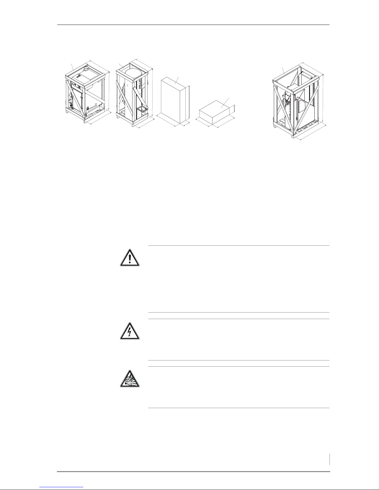
ORIGINAL STATE ON DELIVERY
1Boiler
2 Day container
3Week container
4Cladding
5Ash container
4.4 Installing the heating system
The heating system is installed by specialists from HDG Bavaria
GmbH or an authorised HDG partner and a qualified electrician.
Figure 4/4 - Original state on delivery
612
812
1161
1115
225
515
670
235
660
767
6821
1015
820
5
1
6
1
L
720
(BW 212/262)
670
(BW 102/152)
12
4
5
3
Danger!
Risk of material damage and injury due to incorrect installation
Installing the heating system requires comprehensive specialist
knowledge. If installed by untrained persons, the heating system
can be damaged and persons may be injured due to secondary
damage.
Only allow authorised specialists to perform the installation.
Danger!
Dangerous electrical current or voltage
Switch off the mains supply to the heating system during the
installation.
Danger!
Dust explosion due to build-up of static charge
Only qualified electricians certified according to TRBS 1203-1 may
perform work on electrical systems in areas at risk of explosion.
Page 26
4 Planning and installation – Installing the heating system
26
SUPPLY
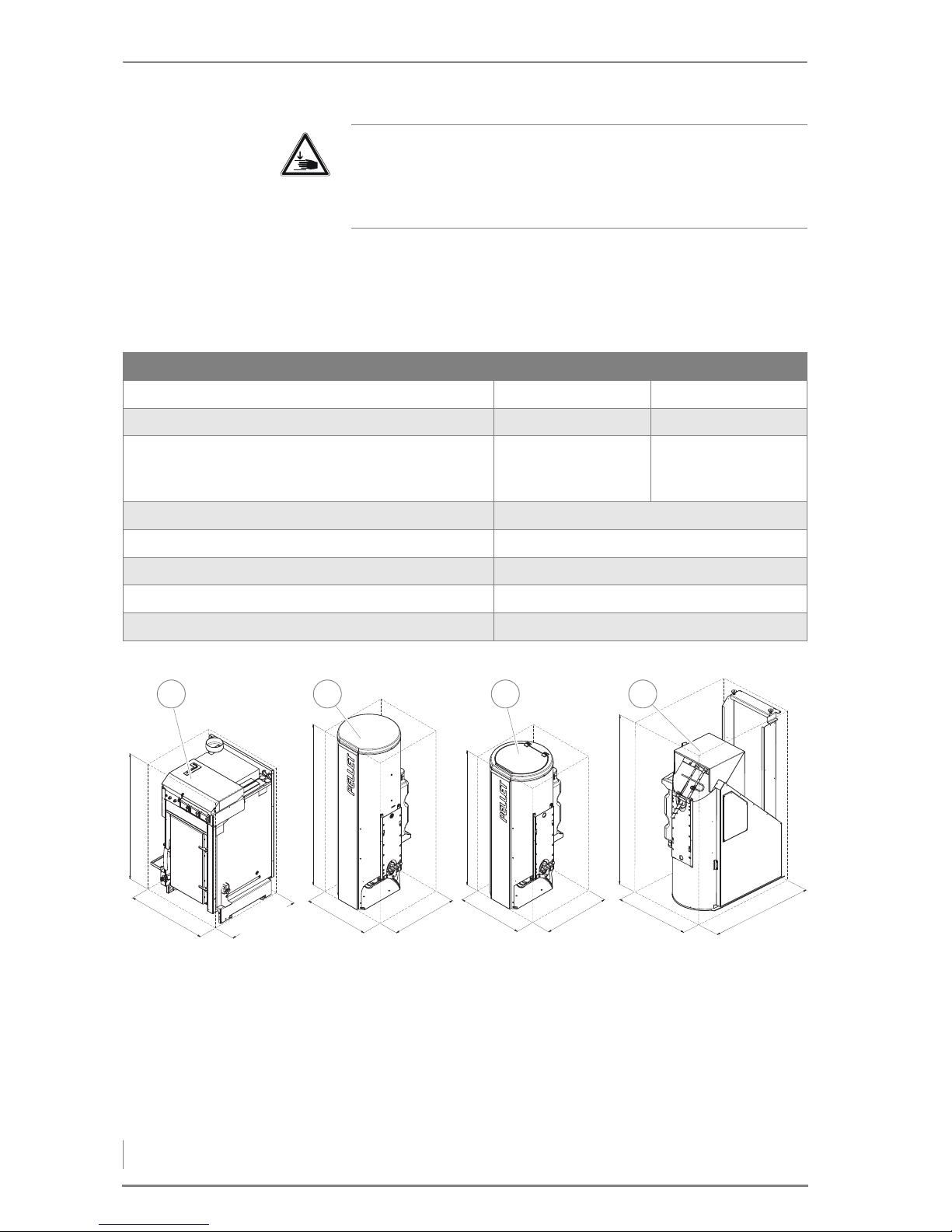
If possible, the boiler and the reservoir are brought by lift truck to the
installation site in their crates.
1Boiler
2 Reservoir with suction system
3 Reservoir with suction system (day container)
4 Week container
Caution!
Danger of injury
Some of the components being installed are heavy. Hands and feet
could be crushed if installation is not performed properly.
Net weight HDG K10/15 HDG K21/26/33
Boiler incl. transport crate 218 kg 239 kg
Boiler 200 kg 221 kg
Minimum boiler weight (without combustion
chamber door, cleaning shaft lid, cone, primary air
pin)
170 kg 191 kg
Day container incl. transport crate 56 kg
Day container 42 kg
Week container incl. transport crate 107 kg
Week container 81 kg
Ash container 12 kg
Table 4/1 - Net weight
Figure 4/5 - Boiler and reservoir without crate
714
650 (BW 102/152)
720 (BW 212/262)
1146
584
592
1231
584
592
1471
680
936
3
7
4
1
714
650 (BW 102/152)
720 (BW 212/262)
1146
584
592
1231
584
592
1471
680
936
3
7
4
1
1 2 3 4
Page 27
4 Planning and installation – Installing the heating system
27
REMOVING THE TRANSPORT PALLET
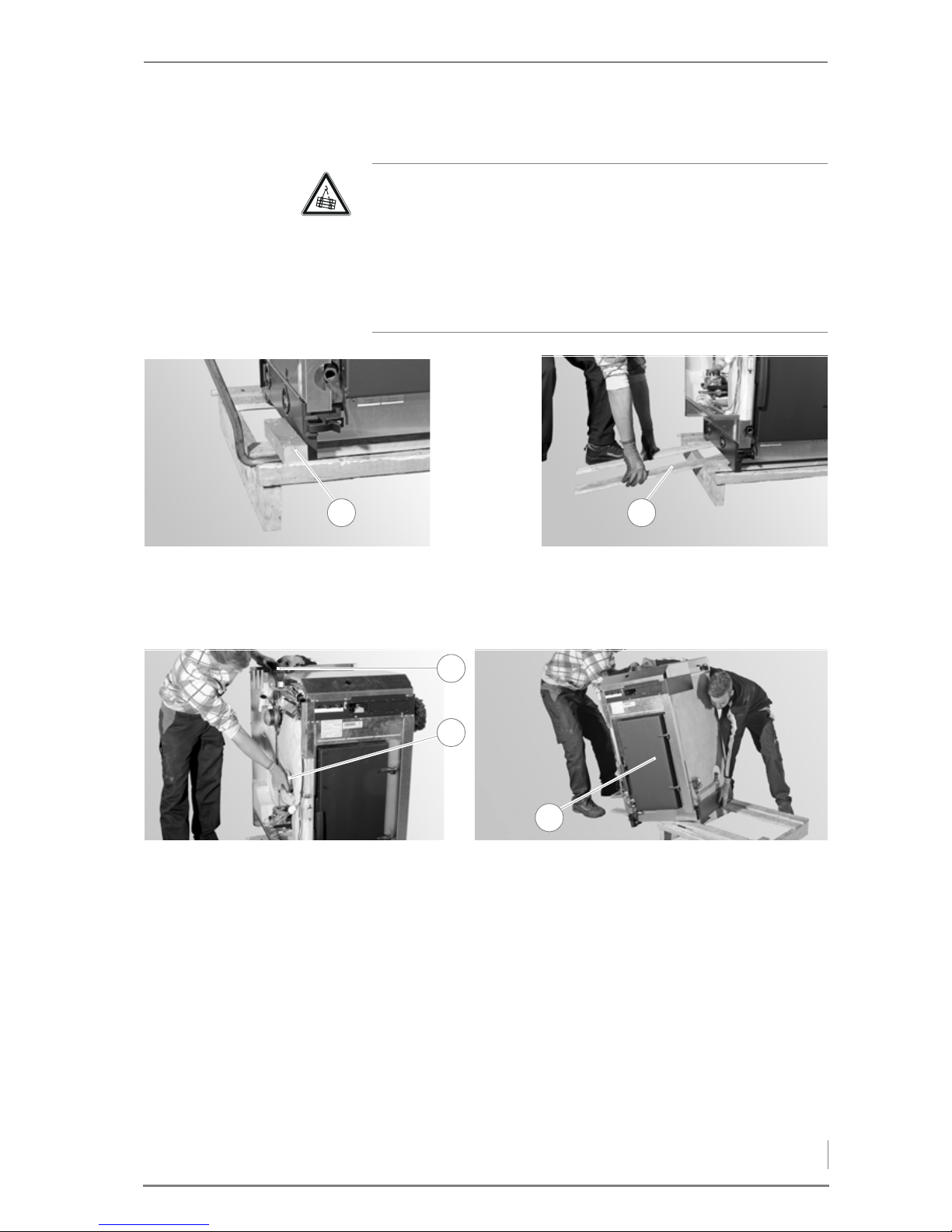
MANUALLY
1. Remove the wood block at the base (1).
2. Lay the dismantled crate planks (2) on the pallet to use as a ramp.
3. Grip into the auger pipe (2) and the flue pipe connection (1).
4. Push the boiler (3) off the pallet.
Caution!
Danger from suspended loads
The boiler weighs over 200 kg. If the boiler is dropped during
transport, persons can be seriously injured and the boiler can be
damaged.
Make sure that you use appropriate lifting gear when installing the
boiler.
Figure 4/6 - Removing the transport pallet - 1
1 2
Figure 4/7 - Removing the transport pallet - 2
2
3
1
Page 28
4 Planning and installation – Installing the heating system
28
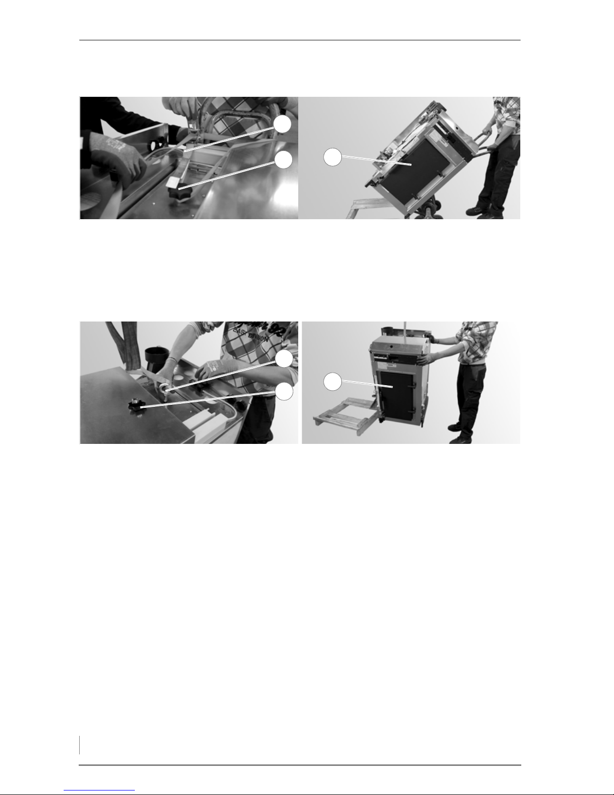
WITH A SACK TRUCK
5. Lay the ratchet strap (1) around the star-grip screw (2) on the
cleaning shaft lid.
6. Fasten the ratchet strap (1) to the sack truck.
7. Lift the boiler (3) off the pallet with the sack truck.
B
Y CRANE
8. Remove the star-grip screw (2) from the cleaning shaft lid.
9. Screw an M12 crane eyelet (1) (not supplied) into the threaded
pin.
10.Lift the boiler (3) off the pallet by crane.
✓ The transport pallet has been removed.
INSTALLING THE BOILER
1. Place the boiler in the planned location.
2. Ensure the minimum clearances.
✎ See section “4.1 Planning the heating system”, under “Required
room sizes and minimum clearances”.
Figure 4/8 - Removing the transport pallet using a sack truck
2
3
1
Figure 4/9 - Removing the transport pallet using a crane
2
3
1
Page 29
4 Planning and installation – Installing the heating system
29
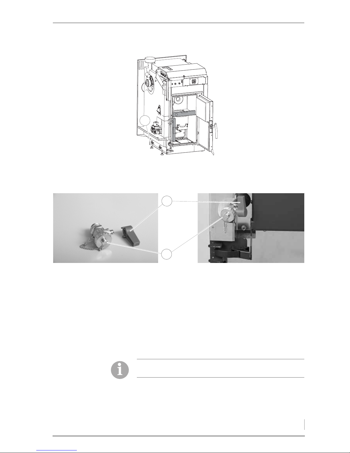
FITTING THE FILLING AND DRAIN COCK
1. Pull the handle (1) off the filling and drain cock (2).
2. Screw the filling and drain cock (2) into the bottom left connection
on the boiler.
3. Make sure the handle is on the right.
4. Push the handle (1) back onto the filling and drain cock (2).
✓ The filling and drain cock is now fitted.
CONVERTING THE FLUE PIPE CONNECTION
3. Adjust the boiler horizontally
or slightly sloping upwards to
the rear using the four
positioning screws (1).
✓ The boiler is erected.
Figure 4/10 - Aligning the boiler
1
Figure 4/11 - Fitting the filling and drain cock
2
1
On delivery, the flue pipe connection is at the top. If necessary, the
flue pipe connection can be moved to the rear.
Page 30
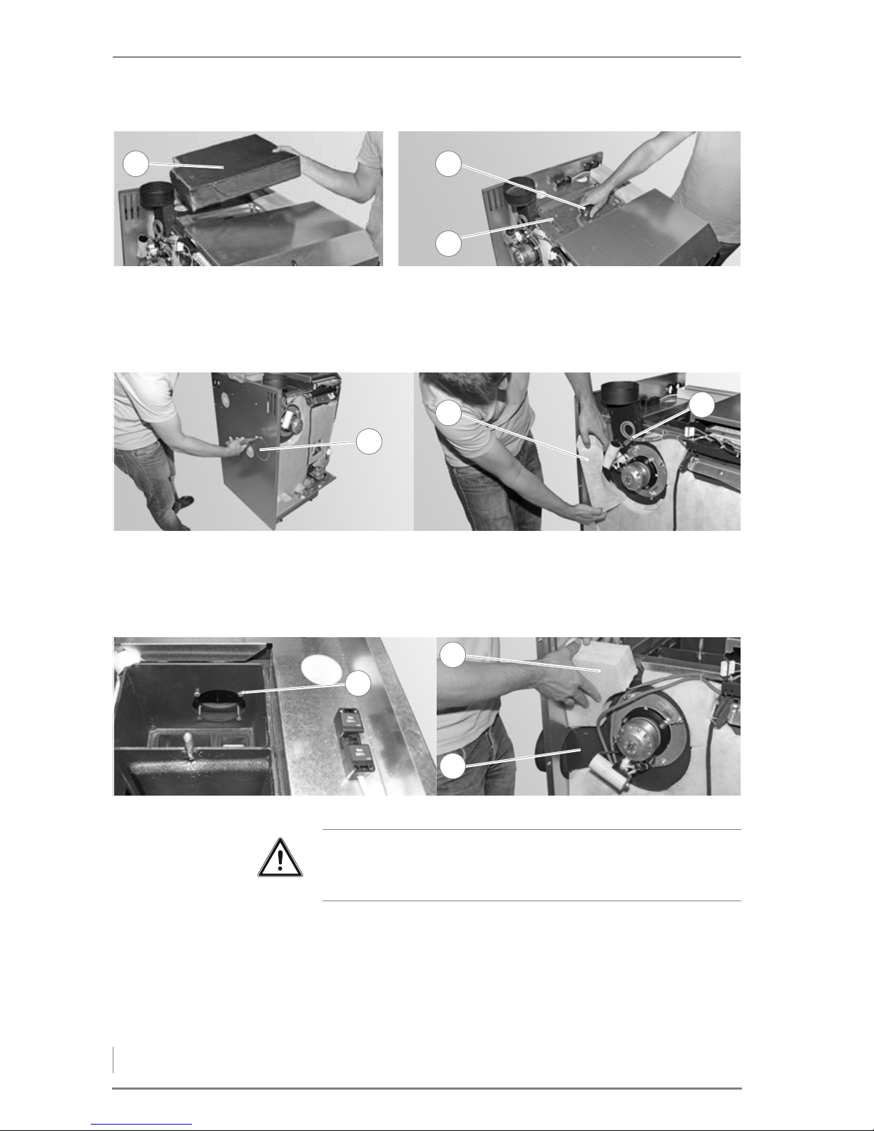
4 Planning and installation – Installing the heating system
30
1. Remove the insulation (1) above the cleaning shaft lid.
2. Release the star-grip screw (2).
3. Lift off the cleaning shaft lid (3).
4. Break out the perforation (1) on the rear wall.
5. Remove the insulation around the (2) flue gas casing.
6. Cut the cable ties (3) on the fan cable.
7. Undo the four hex socket screws (1) in the cleaning shaft lid.
8. Carefully take off the flue gas housing.
9. Turn the flue gas housing (3) by 90° and screw it on again.
10.Put the insulation (2) back in on the left (enclosed, on the side
below the flue gas housing).
✓ The flue gas connection gas been converted.
Figure 4/12 - Opening the cleaning shaft lid
1 2
3
Figure 4/13 - Removing the rear wall
1
2
3
Figure 4/14 - Turning the flue gas housing
1
2
3
Important!
The seal between the flue gas housing and the boiler must not be
damaged.
Page 31
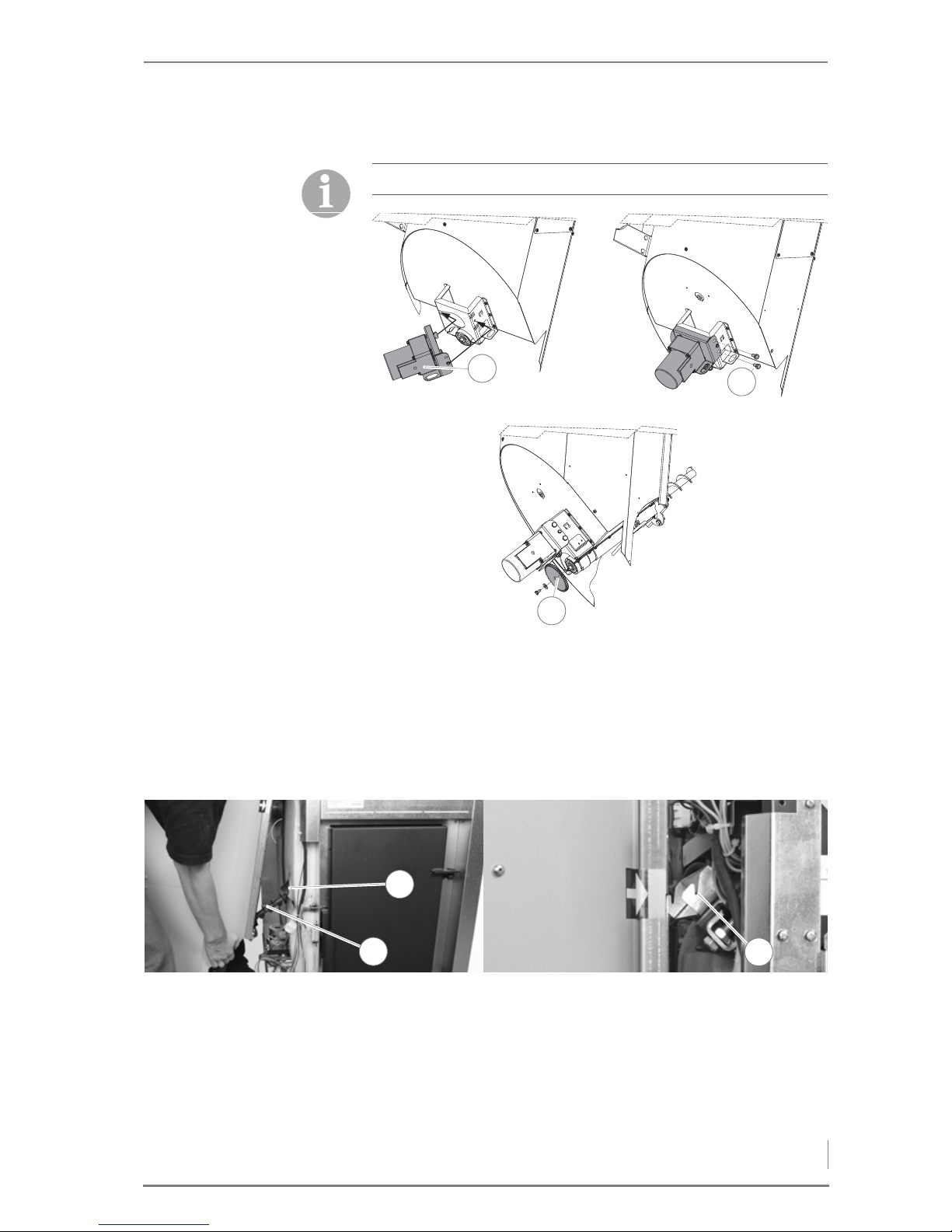
4 Planning and installation – Installing the heating system
31
INSTALLING THE RESERVOIR
1. Attach the auger motor (1) (contained in the combustion chamber
on delivery) to the holder with the lug at the back and the centring
screw at the front.
2. Fasten the auger motor with the two M8 screws (SW13) (2).
3. Screw the gear wheel (3) using the M6 screw (SW10) and a washer
onto the auger at the bottom of the reservoir.
4. Thread the in the reservoir with the conveyor auger (2) into the
auger pipe (1).
5. Attach the reservoir at the top by the yellow markings into the two
hooks (3).
The auger motor is installed under the reservoir on the auger.
Figure 4/15 - Installing the auger motor
1
2
3
2
3
1
Figure 4/16 - Attaching the reservoir
2
3
1
Page 32
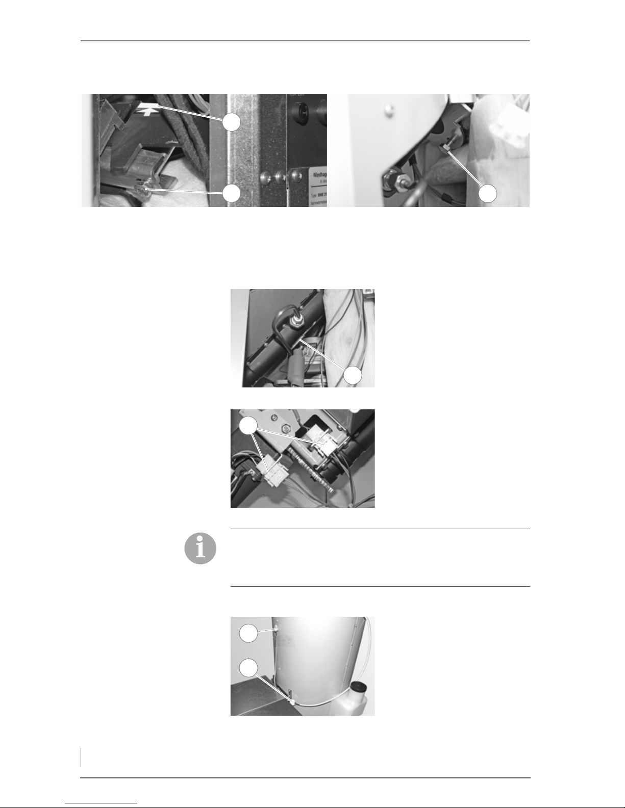
4 Planning and installation – Installing the heating system
32
6. Screw the upper fastening screws (2) all the way in (to the
marking).
7. At the bottom, fasten the reservoir using the M8 screw (SW13)
(enclosed in a plastic bag in the reservoir) (3).
R
ESERVOIR WITH SUCTION
SYSTEM
Figure 4/17 - Fastening the reservoir
2
3
1
8. Push the sensor (1) for the
auger pipe safety thermostat
all the way into the holder.
Figure 4/18 - Installing the safety thermostat
1
9. Connect the plugs (1) of the
auger motor and the
proximity switch.
Figure 4/19 - Connecting the plugs
1
Depending whether or not the reservoir is fitted with a suction
system, either the mains plug and the upper proximity switch, or
corresponding plugs with jumpers must be connected to the
automatic burner.
10.Lay the mains plug (2) from
the vacuum fan to the
automatic burner.
11.Lay the cable from the upper
proximity switch (1) to the
automatic burner.
Figure 4/20 - Connecting the vacuum fan mains plug
1
2
Page 33
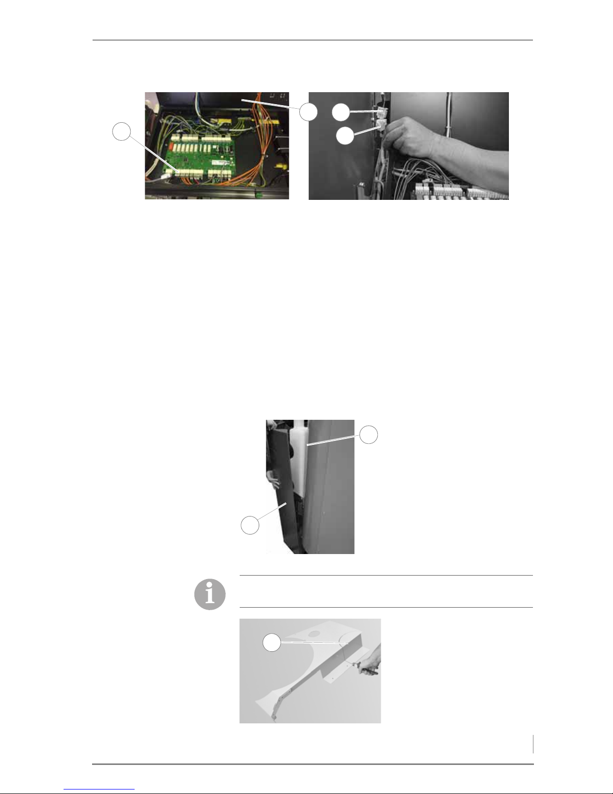
4 Planning and installation – Installing the heating system
33
12.Fold back the cover (2) of the control panel.
13.Connect the line from the upper proximity switch to the plug X22
(1).
14.Connect the mains plug (2) of the vacuum fan to the plug (4) of the
connecting line to the automatic burner.
R
ESERVOIR FOR MANUAL
FILLING
15.Connect the plug (3 pin) with a jumper to the socket X22 (1).
16.Connect the plug (6 pin) with a jumper to the socket (4) for the
vacuum fan mains plug.
✓ The reservoir is installed.
FITTING THE CLADDING
RESERVOIR CLADDING
Figure 4/21 - Connecting in the plugs and jumpers
4
1
3
2
1. Attach the rear cladding (2) to
the pins (1) on the reservoir
and the rear cladding of the
boiler.
Figure 4/22 - Fitting the rear cladding
2
1
If the flue pipe connection is fitted at the top, the upper cladding of
the reservoir must be broken out.
2. Break out the perforation (1)
on the rear wall if necessary.
Figure 4/23 - Breaking out the upper left cladding
1
Page 34
4 Planning and installation – Installing the heating system
34
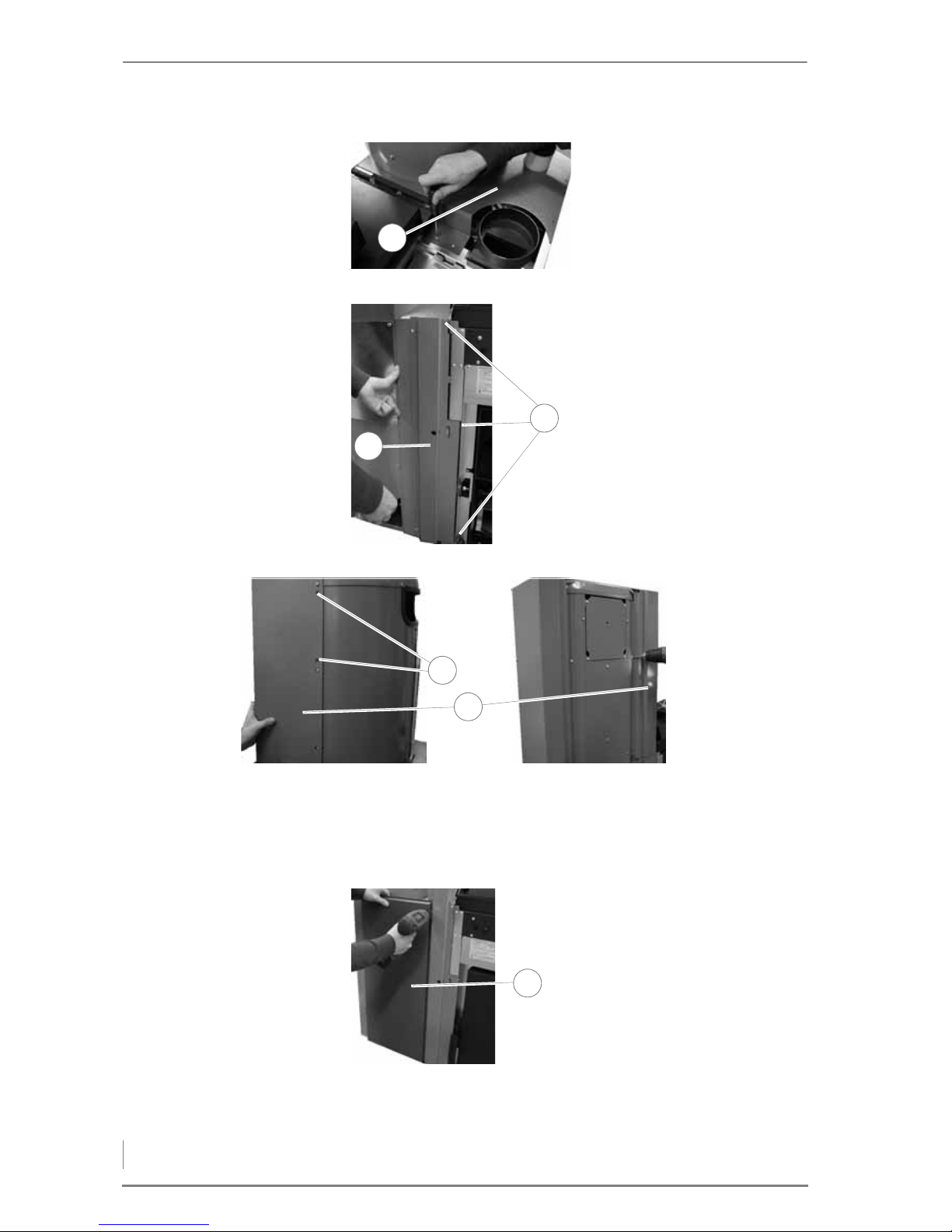
7. Mount the right container cladding (2) to the side of the reservoir
on the 2nd and 3rd hole (1) from the top with the Torx screws.
8. Mount the right container cladding (2) to the front of the reservoir
with the Torx screws.
3. Place the upper cladding (1)
above the water tank onto the
boiler.
4. Mount the upper cladding (1)
with the Phillips screws.
Figure 4/24 - Installing the upper cladding
1
5. Push the middle orifice plate
(1) under the cladding or
sideways into the recesses on
the boiler.
6. Fasten the middle orifice
plate (1) with the Phillips
screws (2).
Figure 4/25 - Mounting the middle orifice plate
1
2
Figure 4/26 - Mounting the right container cladding
2
1
9. Mount the lower front
cladding (1) with the coated
Torx screws on the middle
orifice plate and the left
container cladding.
Figure 4/27 - Installing the front cladding at the bottom
1
Page 35
4 Planning and installation – Installing the heating system
35
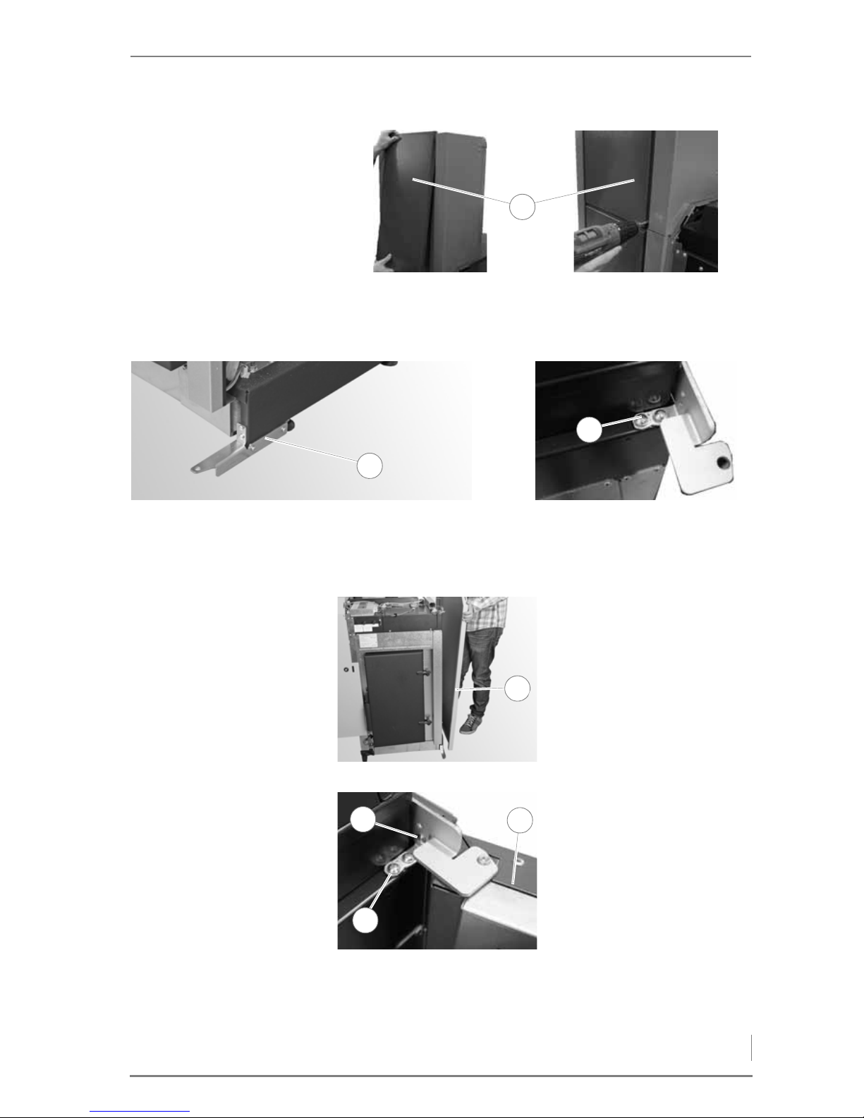
10.Hang the front cladding (1) in the left and right container cladding
and fasten it at the bottom with the Torx screws.
B
OILER CLADDING
11.Mount the lower door hinge (1) with the four Torx screws.
12.Mount the upper door hinge (2) loosely - so that it can still move -
with the two Phillips screws.
Figure 4/28 - Installing the front cladding at the top
1
Figure 4/29 - Mounting the door hinges
1
2
13.Attach the side wall (1).
Figure 4/30 - Attaching the side wall
1
14.Hang the housing door (3) in
the upper and lower hinge.
15.Tighten the Phillips screws (2)
of the upper door hinge.
16.Fasten the side wall with the
Phillips screw (1).
Figure 4/31 - Mounting the housing door and the side wall
3
1
2
Page 36
4 Planning and installation – Installing the heating system
36
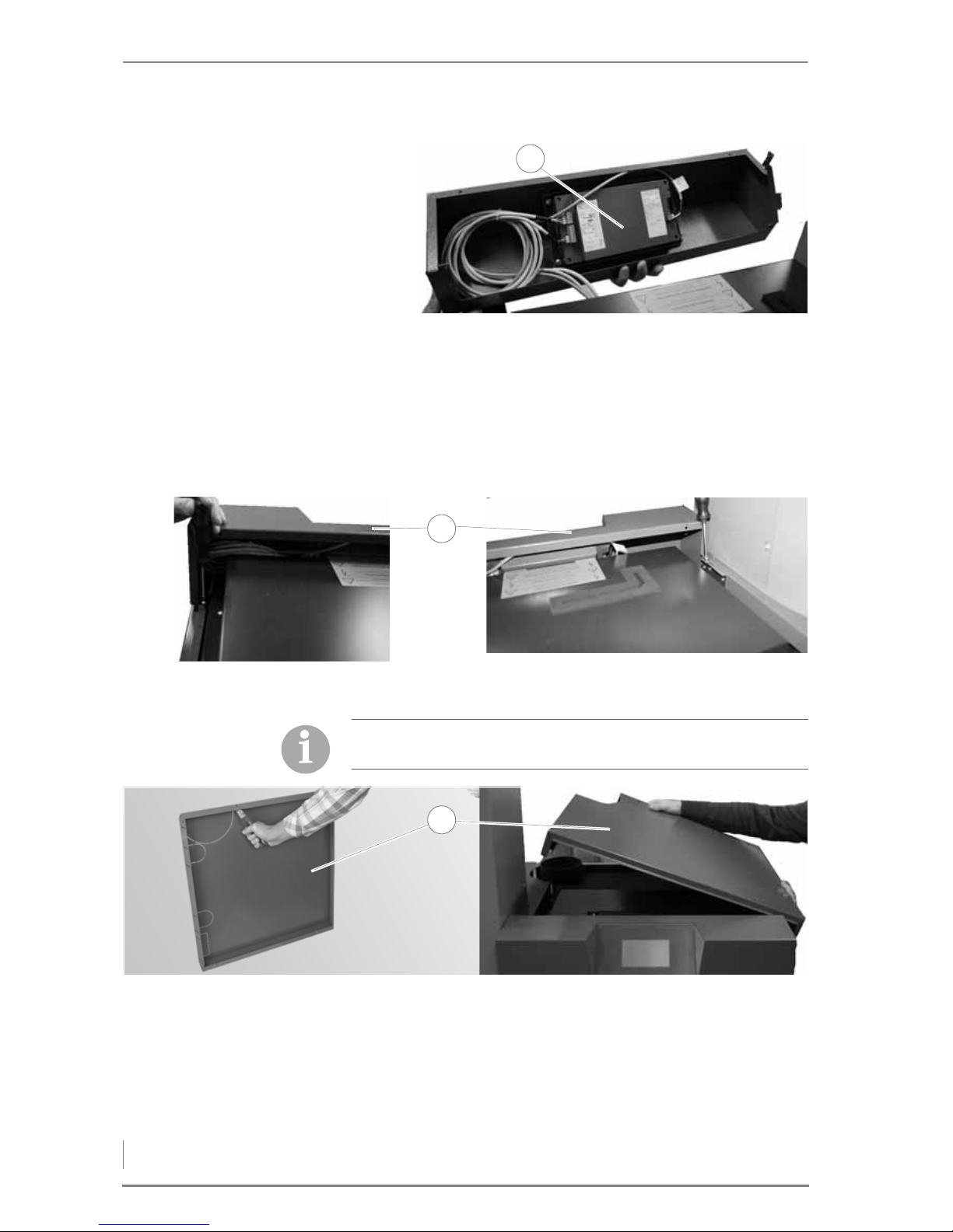
17.Fit the control panel (1) on the support plate from the rear with
the four Phillips screws.
18.Plug the outside temperature sensor – if present – into the control
unit.
19.Connect the connecting lines according to the control unit (1).
✎ See “Electrical plans for HDG K10 - 60”.
20.Mount the support plate (1) with the Phillips screws.
21.Break out the perforation on the upper cover (1) if necessary.
22.Place the upper cover (1) on the boiler.
✓ The cladding is installed.
Figure 4/32 - Installing the control unit
1
Figure 4/33 - Mounting the support plate
1
If the flue pipe connection is fitted at the top, the upper cover must
be broken out.
Figure 4/34 - Installing the upper cover
1
Page 37
4 Planning and installation – Installing the heating system
37
INSTALLING THE ASH CONTAINER
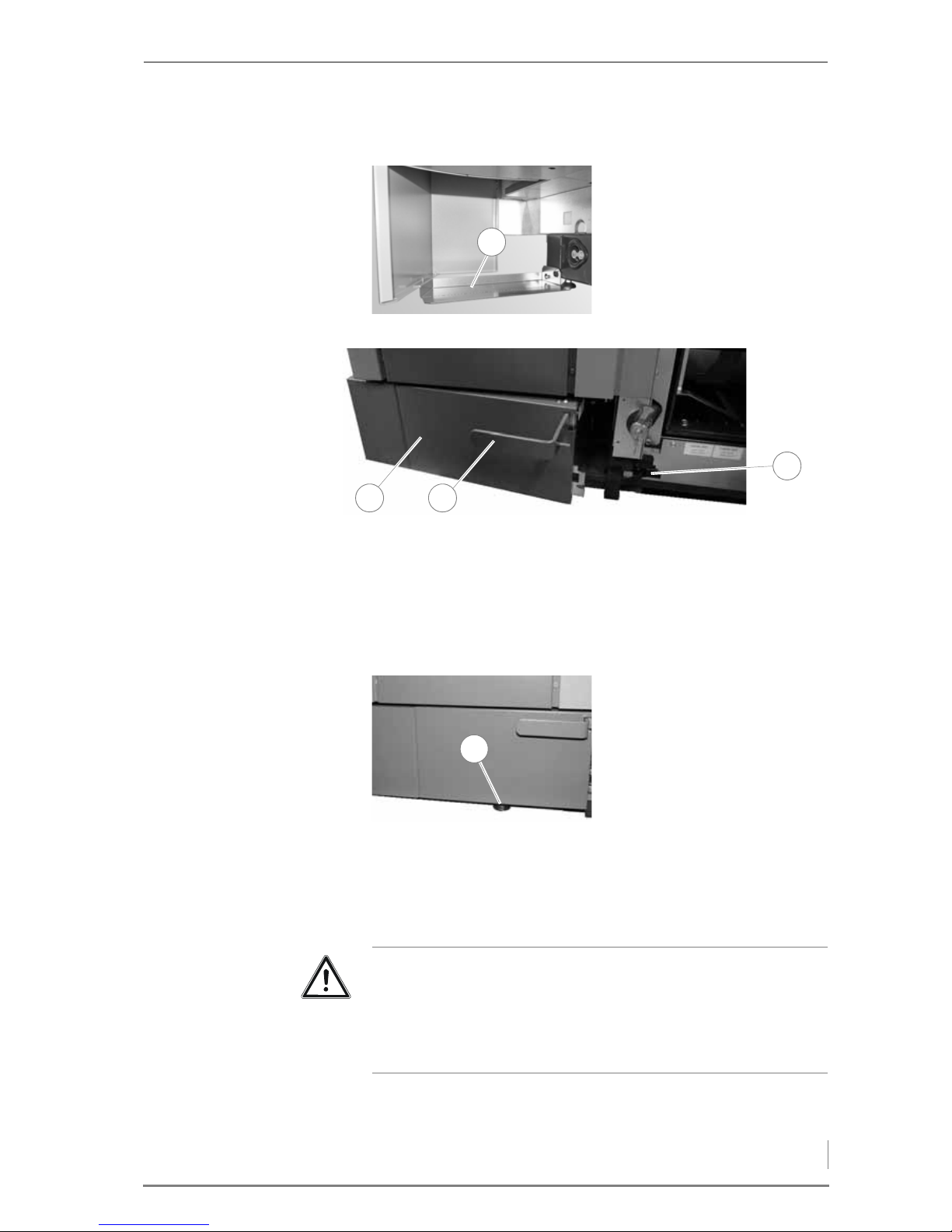
1. Push the ash container (1) diagonally from the left under the
reservoir.
2. Push the handle (2) all the way in.
✓ The opening s in the ash container are open.
3. Close the clamp lock (3).
✓ The ash container is installed.
MOUNTING THE EXPANSION MODULES
1. Attach the base plate (1)
under the reservoir on the
boiler and bend the front part
down to the ground.
Figure 4/35 - Mounting the base plate
1
Figure 4/36 - Mounting the support plate
1
3
2
4. Adjust the foot (1) of the ash
container.
Figure 4/37 - Adjusting the foot
1
Important!
If an EM4 or EM8 expansion module is used, these can be mounted
directly on the plate above the automatic burner.
✎ For connecting the expansion module, see the “Electrical plans
for the HDG K10 - 60”.
Page 38
4 Planning and installation – Installing the heating system
38
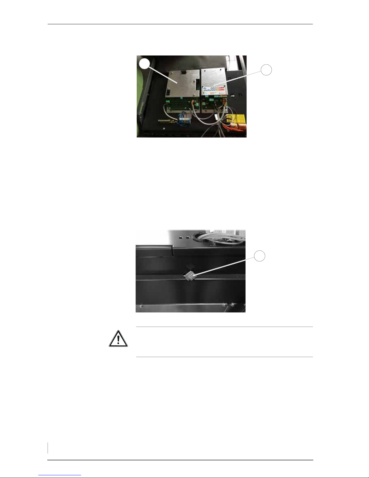
1. Mount the EM4 expansion module (2) if necessary.
2. Mount the EM8 expansion module (1) if necessary.
3. Connect the EM4 expansion modules (1 + 2).
✎ See “Electrical plans for HDG K10 - 60”.
4. Install the cables and sensors on the expansion modules
according to the hydraulic wiring diagram.
✓ The EM4 / EM8 expansion modules are fitted.
S
ERVICE PLUG
Figure 4/38 - Mounting the expansion modules
2
1
Figure 4/39 - Service plug
1
Important!
The service plug (1) is only intended for HDG customer service and
may not be connected to any module!
Page 39
4 Planning and installation – Connecting the chimney
39
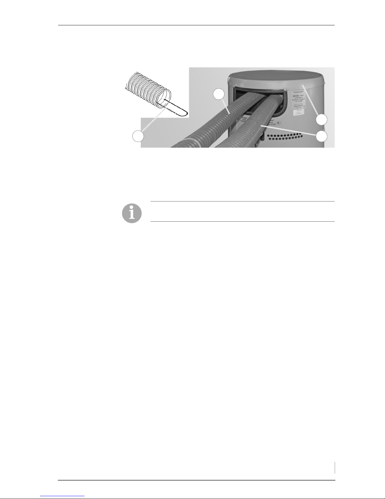
CONNECTING THE SUCTION AND RETURN HOSES
1. Lay bare about 10 cm of the end of the braid (1) embedded in the
return hose.
2. Bend the braid (1) inwards into the hose.
3. Undo the four screws and remove the cover (4) of the reservoir.
4. Fit the suction hose (2) with a hose clip on the left connecting port
of the reservoir.
5. Fit the return hose (3) with a hose clip on the right connecting port
of the reservoir.
✓ The suction and return hose is connected.
4.5 Connecting the chimney
1. Connect the flue gas pipe to the chimney connection.
2. Make sure that the connecting piece does not protrude into the
chimney.
3. Seal the connection to the chimney with highly fireproof silicone
or with a suitable mortar.
✓ The boiler is now connected to the chimney.
4.6 Electrical system
The electrical connections should be made in accordance with VDE
guideline 0100, “Electrical systems in buildings”.
✎ The technical details are described in chapter “3 Mode of
operation”, section “3.3 Technical data”.
✎ The circuit diagrams for the HDG K10 - 33 can be found in
“Electrical plans for the HDG K10 - 60”. The connections for the
mains supply line can also be found in this document.
Figure 4/40 - Removing the packaging
1
4
3
2
In the event that the connections do not move easily when
attached, only moisten with water (do not use grease).
Page 40

4 Planning and installation – Water
40
4.7 Water
The diaphragm expansion vessel must be constructed in accordance
with DIN EN 13831 “Closed expansion vessels with built-in
diaphragm for integration in water installations”. Before putting the
system into operation, the pressure of the diaphragm expansion
vessel must be adjusted for the conditions in the heating system and
in the building.
After putting the system into operation, heat up the system to the
maximum boiler temperature and bleed air from the system again to
make sure that there are no air pockets.
The safety devices must be implemented in accordance with DIN EN
12828 “Heating systems in buildings” and the correspondingly
harmonised national standard DIN 4751, Part 2 “Closed,
thermostatically safeguarded heat generating systems with supply
temperatures of up to 120°C; safety equipment”.
In Germany, the requirements of the German energy conservation
ordinance (EnEV) must be met.
Important!
The heating system must be filled with water in accordance with
VDI guideline 2035, “Avoiding damage in hot water heating
systems”.
Page 41
5 Commissioning the system – Requirements
41
5 Commissioning the system
The heating system is initially commissioned by specialists from HDG
Bavaria or from an authorised HDG partner.
The commissioning includes an introduction to the operation and
maintenance of the heating system as well as performing
measurements on the system to determine exhaust emissions and
firing performance.
5.1 Requirements
The following conditions must be met before the system can be
commissioned without faults:
S
WITCH OFF THE MAINS SUPPLY • Is the circuit breaker of the mains supply to the heating system
switched off?
C
HECK THE MECHANICAL
ASSEMBLY
• Have the system components been correctly installed?
• Have all of the mechanical components been firmly screwed
together?
• Does the mechanical structure of the boiler meet the
specifications of this operating manual?
• Has the water tank been filled with water?
C
HECK THE HYDRAULIC
CONNECTIONS
• Do the hydraulic connections meet the specifications of this
operating manual?
• Has the safety equipment been installed to conform to the
applicable standards and guidelines?
• Has the system been flushed, filled and bled (heat transfer must
be possible)?
C
HECK THE ELECTRICAL
CONNECTIONS
• Are all of the sensors and actuators correctly connected and
properly plugged in to the control panel?
• Has the mains power supply cable been correctly connected?
Danger!
Material damage and injury due to incorrect commissioning
Commissioning the system requires comprehensive expertise. If
this commissioning is done by an untrained person, the heating
system could be damaged.
Only allow authorised specialists to perform the commissioning.
Danger!
Dangerous electrical current or voltage
Isolate the mains cable to the heating system.
Page 42
5 Commissioning the system – Procedure
42
FUEL • Is there a sufficient quantity of fuel?
5.2 Procedure
✎ See also operating manual “HDG Control”, Chapter “4
Commissioning the system”.
SETTING THE FUEL QUANTITY
1. Start the conveyor auger in manual mode.
2. Collect the pellets with a suitable container.
3. Repeat the cycle two (with HDG K21/26/33) or three times (with
HDG K10/15).
4. Weigh the amount of pellets collected in the second or third cycle.
5. Multiply the weight by a factor of 10 (= fuel quantity in kg/h).
6. Enter the calculated value in the boiler control system.
✎ See operating manual “HDG Control”, chapter “7 HDG K10 - 60
parameters”.
✓ The fuel quantity has been calculated.
PERFORM ACTUATOR TEST
In addition to the automatic self-test, individual actuators can also be
manually activated as required.
✎ See operating manual “HDG Control”, chapter “7 HDG K10 - 60
parameters”.
ADAPTING PARAMETERS
If the heating system does not work correctly, the parameters must
be adjusted accordingly.
✎ See operating manual “HDG Control”, chapter “7 HDG K10 - 60
parameters”.
Important!
Commission the HDG K10 - 33 heating system in accordance with
the specifications from the supplied commissioning protocol.
One cycle of the conveyor auger lasts 6 mins.
Page 43
6 Using the heating system – Control unit for HDG Control
43
6 Using the heating system
6.1 Control unit for HDG Control
✎ You can find all information and instructions for setting up and
operating the boiler and weather-compensated heating control
of the HDG Control in the “HDG Control” operating manual.
6.2 Filling the pellet storage room
REQUIREMENTS
The following requirements must be met before the pellet storage
room can be filled:
• The pellet storage room has been initially approved by an
authorised specialist.
• The pellet storage room is dry and free of any foreign bodies.
• Thick layers of dust must be removed.
✎ See chapter “3 Mode of operation”, section “3.4 Fuel quality
requirements”.
• The requirements of government safety organisations must be
met.
PROCEDURE
1. Switch the heating system off.
✓ See the “HDG Control” operating manual, chapter “5 Using the
control unit”, section “5.3 Switching off the heating system”.
2. Double check that the heating system is switched off.
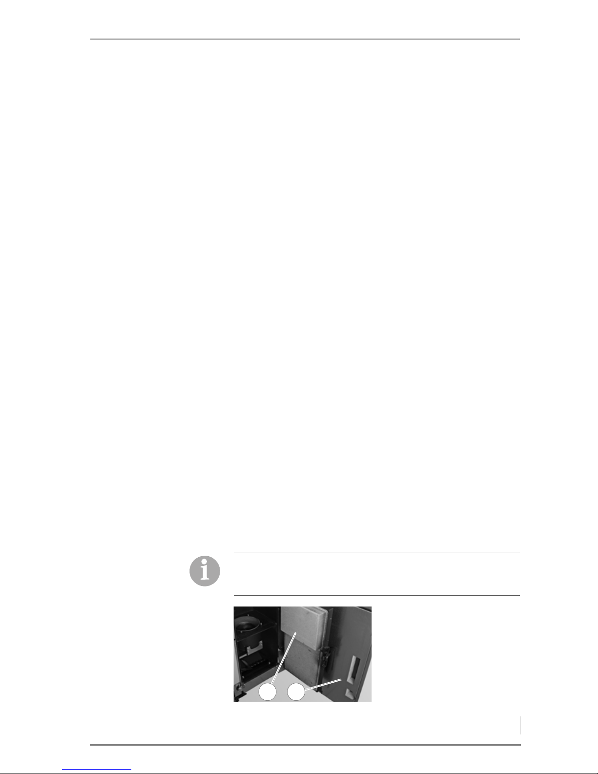
To prevent negative pressure from being created in the boiler
during filling of the pellet storage room, you can open the
combustion chamber door.
3. Open the housing door (2).
4. Open the combustion
chamber door (1).
Figure 6/1 - Opening the doors
21
Page 44

6 Using the heating system – Filling the reservoir
44
5. Inform the tanker driver that the pellet storage room can be filled.
6. After filling is completed, close the injection and extraction
nozzles.
7. Close the reservoir inspection hatch.
9. Switch the heating system on.
✎ See the “HDG Control” operating manual, chapter “5 Using the
control unit”, section “5.2 Switching on the heating system”.
✓ The filling of the pellet storage is completed.
6.3 Filling the reservoir
MANUAL FILLING When operating without an automatic pellet suction system, the
reservoir is manually filled.
1. Open the reservoir cover.
2. Fill the reservoir with pellets up to a maximum of 1 cm below the
rim.
✓ The reservoir is filled.
P
ELLET SUCTION SYSTEM The reservoir is filled by the automatic pellet suction system. Initial
filling is performed during commissioning of the system. Each further
filling is automatic as required by the boiler control system.
6.4 Performing a chimney sweep measurement
✎ See the “HDG Control” operating manual, chapter “5 Using the
control unit”, section “5.8 Performing a chimney sweep
measurement”.
8. Document the filling of the
storage room on the “Filling
the fuel storage room” sticker.
Figure 6/2 - Filling the fuel storage room
002357/00
01/2010
Befüllung Lagerraum
Filling date and volume
Remplissage du silo de stockage
Datum/Date/Date
Menge/Volume/Quantité
kg
kg
kg
kg
kg
kg
kg
kg
kg
kg
kg
kg
kg
kg
kg
kg
kg
kg
kg
kg
kg
kg
kg
Page 45
6 Using the heating system – Switching off the heating system for repair work
45
6.5 Switching off the heating system for repair
work
1. Allow the fire in the boiler to burn out and cool off.
2. Switch the heating system off.
✎ See the “HDG Control” operating manual, chapter “5 Using the
control unit”, section “5.3 Switching off the heating system”.
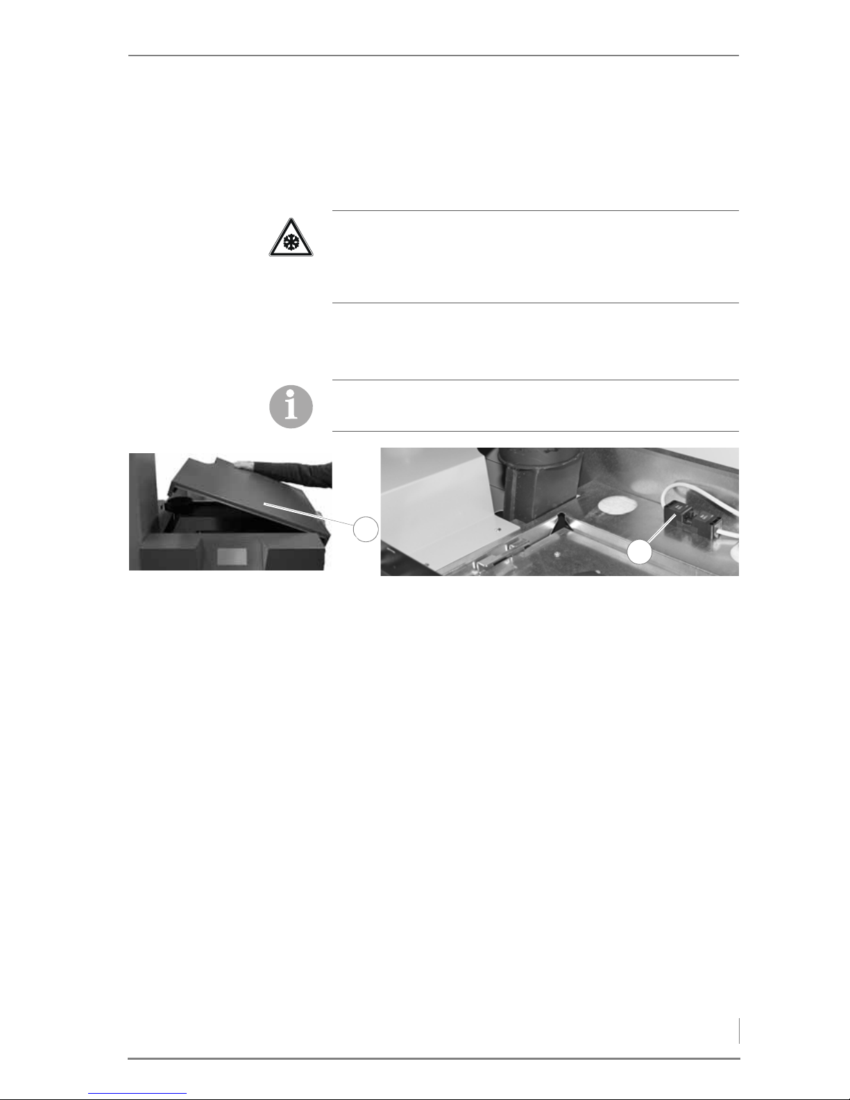
3. Lift off the top right cover (1) of the boiler.
4. Pull out the machine’s mains plug (2).
✓ The heating system is switched off and without current.
Important!
Frost danger
Only completely shut off the power to the heating system if the
danger of frost can be ruled out.
There is still electrical voltage in the system.
Figure 6/3 - Removing the mains plug
1
2
Page 46
7 Cleaning and servicing the heating system – Cleaning and servicing schedule
46
7 Cleaning and servicing the
heating system
GENERAL INFORMATION To ensure fault-free and safe operation, certain cleaning and
maintenance work is necessary. This effort will also help you avoid
expensive repairs, provided you observe the recommended
intervals.
The cleaning and maintenance work can also be performed by an
authorised specialist heating company where a servicing contract
has been concluded.
The HDG K10 - 33 heating system is fitted a cleaning and de-ashing
interval display. The "clean" or “main cleaning” prompt appears on
the boiler control system display and must be reset after cleaning/
de-ashing.
S
PARE PARTS
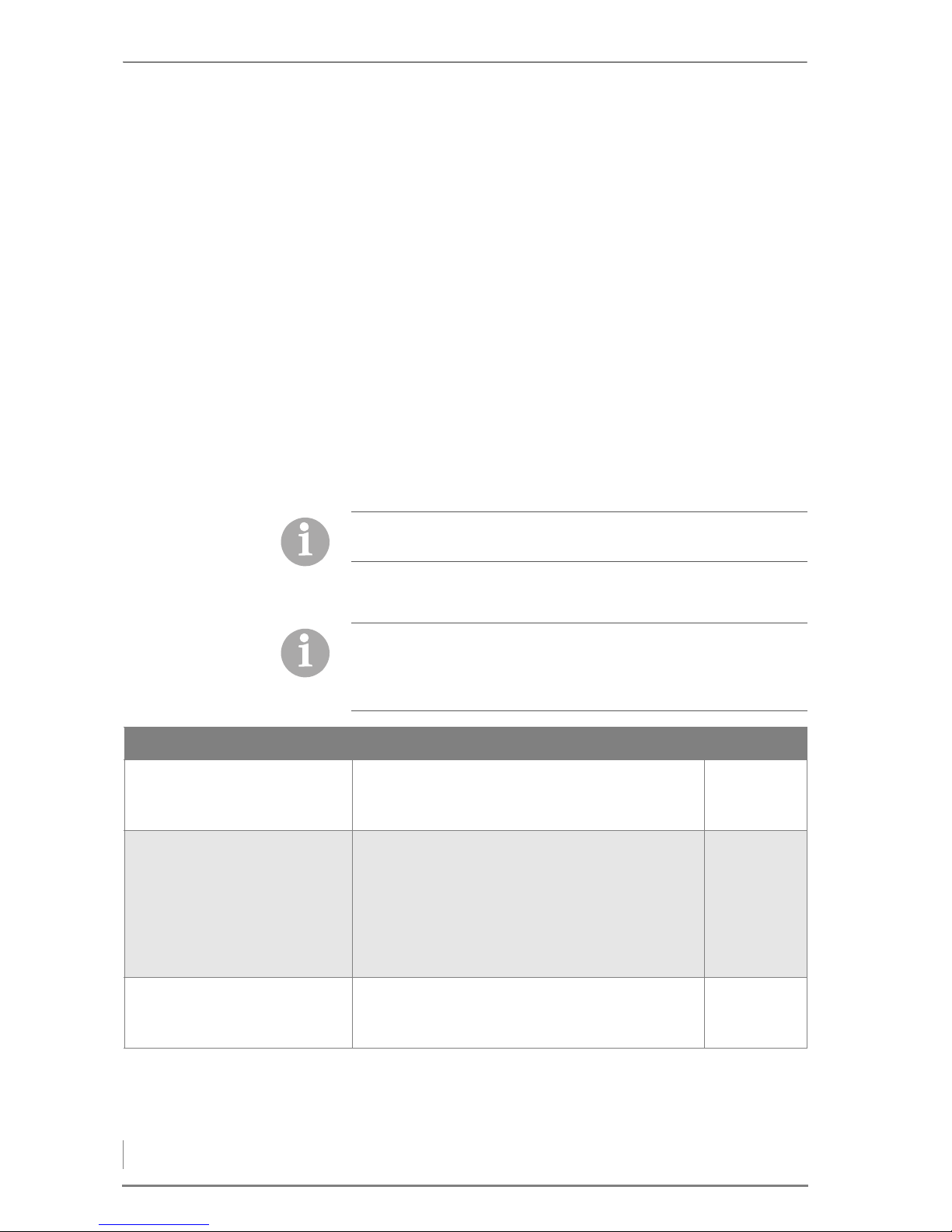
7.1 Cleaning and servicing schedule
Only use genuine HDG spare parts. You can obtain HDG spare parts
from your specialist heating company.
The specified cleaning intervals are guidelines.
Depending on the quality of the pellets and the power used by the
heating system (more frequent on/off operation) the intervals may
be extended.
Interval Component See page ...
Indication in display:
Cleaning
Emergency cleaning
• Empty the ash box
• Clean the combustion chamber and burner pot
(Confirm cleaning)
48
49
Indication in display:
Main cleaning
Emergency main
cleaning
or
At least 1 x per heating period
• Clean flue gas fan and cleaning shaft
• Clean the flue gas pipe
• Check the fill level of the water tank
• Check and clean the reservoir and flap of the
delivery unit
• Clean the pellet storage room
(Confirm main cleaning)
52
53
53
54
56
Indication in display:
Mainten.
• Have maintenance carried out by HDG or an
authorised specialist heating installer within 3
months
Table 7/1 - Cleaning and servicing schedule
Page 47
7 Cleaning and servicing the heating system – Procedure
47
7.2 Procedure
GENERALLY APPLICABLE SAFETY INSTRUCTIONS
Warning!
Danger of asphyxiation due to lack of oxygen
If the boiler is in operation, carbon monoxide can be emitted
through the open doors, lids or other cleaning openings.
When performing cleaning and maintenance work, do not leave the
cleaning openings, doors and lids open any longer than necessary.
Caution!
Danger of burns from hot surfaces
During operation, the boiler surfaces under the cladding are hot.
Even when turned off, they only cool down slowly.
Switch the heating system off and only start with the cleaning and
maintenance work when the surfaces have cooled down.
Caution!
Danger of fire from combustion residues
Hot combustion residues (ash, coal etc) can pose the danger of fires.
Allow the hot combustion residues to cool down in the cleaning
and maintenance work before pouring these into a non-flammable
container.
Turn the heating system off before carrying out the tasks described
below.
✎ See chapter “6 Using the heating system”, section “6.5 Switching
off the heating system for repair work”.
Only turn the heating system back on again after carrying out the
tasks described below.
✎ See the “HDG Control” operating manual, chapter “5 Using the
control unit”, section “5.2 Switching on the heating system”.
Page 48
7 Cleaning and servicing the heating system – Procedure
48
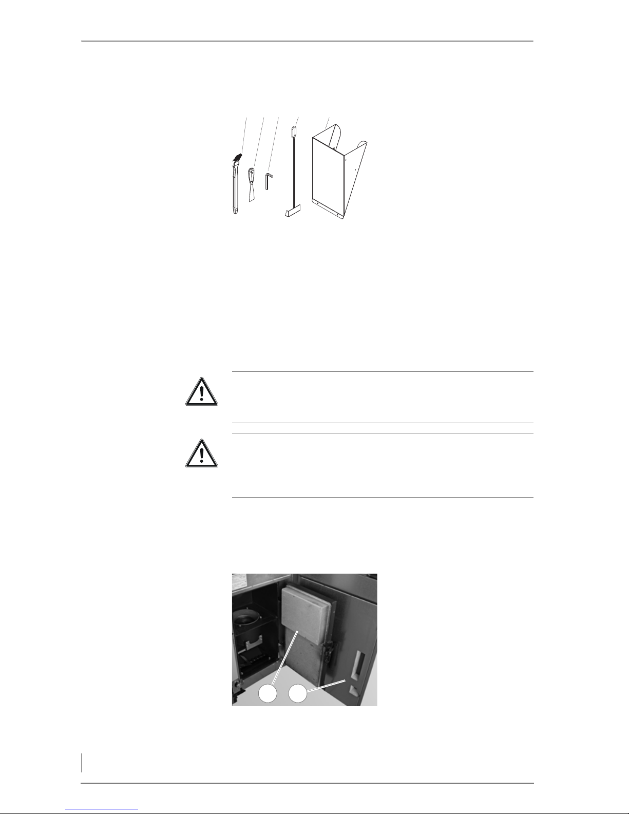
CLEANING TOOLS
1 Cleaning brush
2Scraper
3Allen key
4Scraper
5 Pellet scuttle (optional)
EMPTYING THE ASH CONTAINER
1. Switch the heating system off.
✎ See the “HDG Control” operating manual, chapter “5 Using the
control unit”, section “5.3 Switching off the heating system”.
2. Allow the fire in the heating system to burn out and cool down.
Figure 7/1 - Cleaning tools
1 2 3 4 5
Important!
Observe the “Generally applicable safety instructions” in this
section.
Important!
The combustion chamber door must not be opened during
continuous operation. Always switch off the boiler first and wait
until burn-out mode has finished.
3. Open the housing door (2).
4. Open the combustion
chamber door (1).
Figure 7/2 - Opening the doors
21
Page 49
7 Cleaning and servicing the heating system – Procedure
49
9. Open the lid of the ash container (1) and empty the combustion
residues into a non-flammable container.
10.Reinstall the ash container (1) in the reverse sequence.
11.Re-starting the heating system.
✎ See the “HDG Control” operating manual, chapter “5 Using the
control unit”, section “5.2 Switching on the heating system”.
✓ The ash container has been emptied.
CLEANING THE COMBUSTION CHAMBER AND BURNER POT
1. Switch the heating system off.
✎ See the “HDG Control” operating manual, chapter “5 Using the
control unit”, section “5.3 Switching off the heating system”.
2. Allow the fire in the heating system to burn out and cool down.
3. Open the housing door and the combustion chamber door.
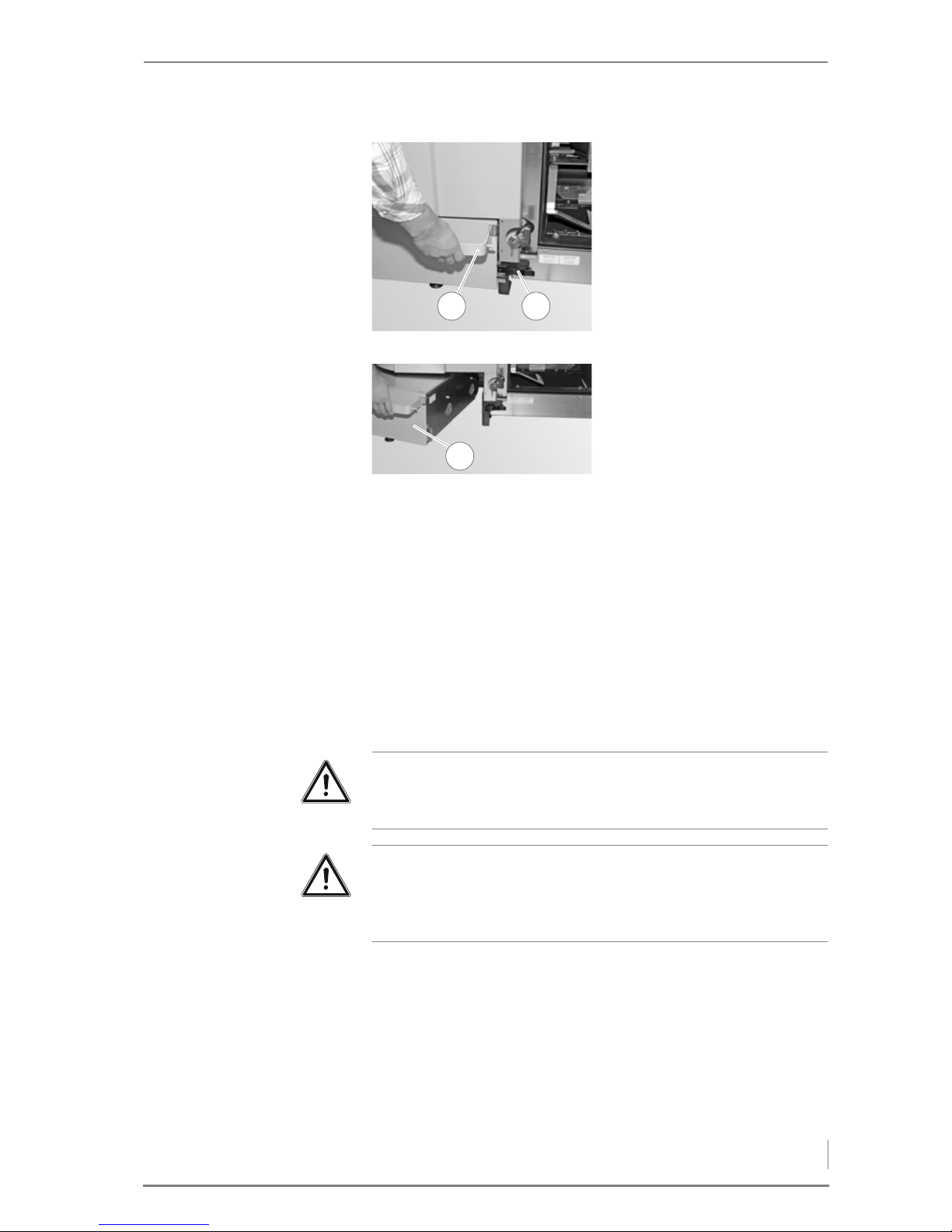
5. Pull the handle (1) of the ash
container all the way out.
✓ The side openings of the ash
container are locked.
6. Release the lower right clamp
lock (2).
Figure 7/3 - Locking the ash container
21
7. Push the ash container (1)
slightly to the left.
8. Pull out the ash container (1).
Figure 7/4 - Removing the ash container
1
Important!
Observe the “Generally applicable safety instructions” in this
section.
Important!
The combustion chamber door must not be opened during
continuous operation. Always switch off the boiler first and wait
until burn-out mode has finished.
Page 50
7 Cleaning and servicing the heating system – Procedure
50
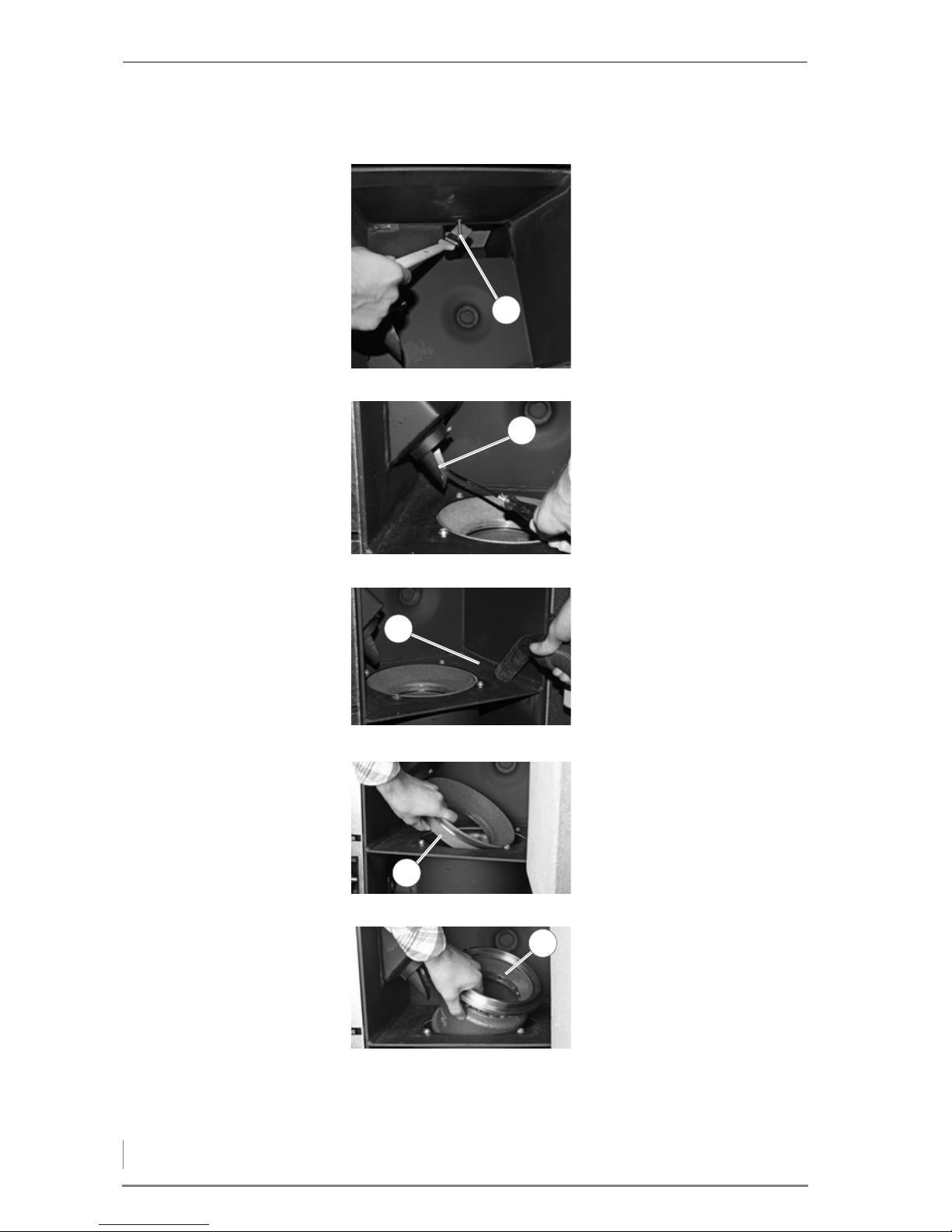
CLEANING THE COMBUSTION
CHAMBER
C
LEANING THE BURNER POT
4. Clean the combustion
chamber temperature sensor
(1) using the cleaning brush.
Figure 7/5 - Cleaning the combustion chamber temperature sensor
1
5. Clean the drop chute (1) if
necessary, for example using
a screwdriver.
Figure 7/6 - Cleaning the drop chute
1
6. Remove the combustion
residue from the combustion
chamber with a vacuum
cleaner.
Figure 7/7 - Cleaning the combustion chamber
1
7. Lift the upper part of the cone
(1) out of the burner pot.
Figure 7/8 - Removing the upper part of the cone
1
8. Lift the lower part of the cone
(1) out of the burner pot.
Figure 7/9 - Removing the lower part of the cone
1
Page 51
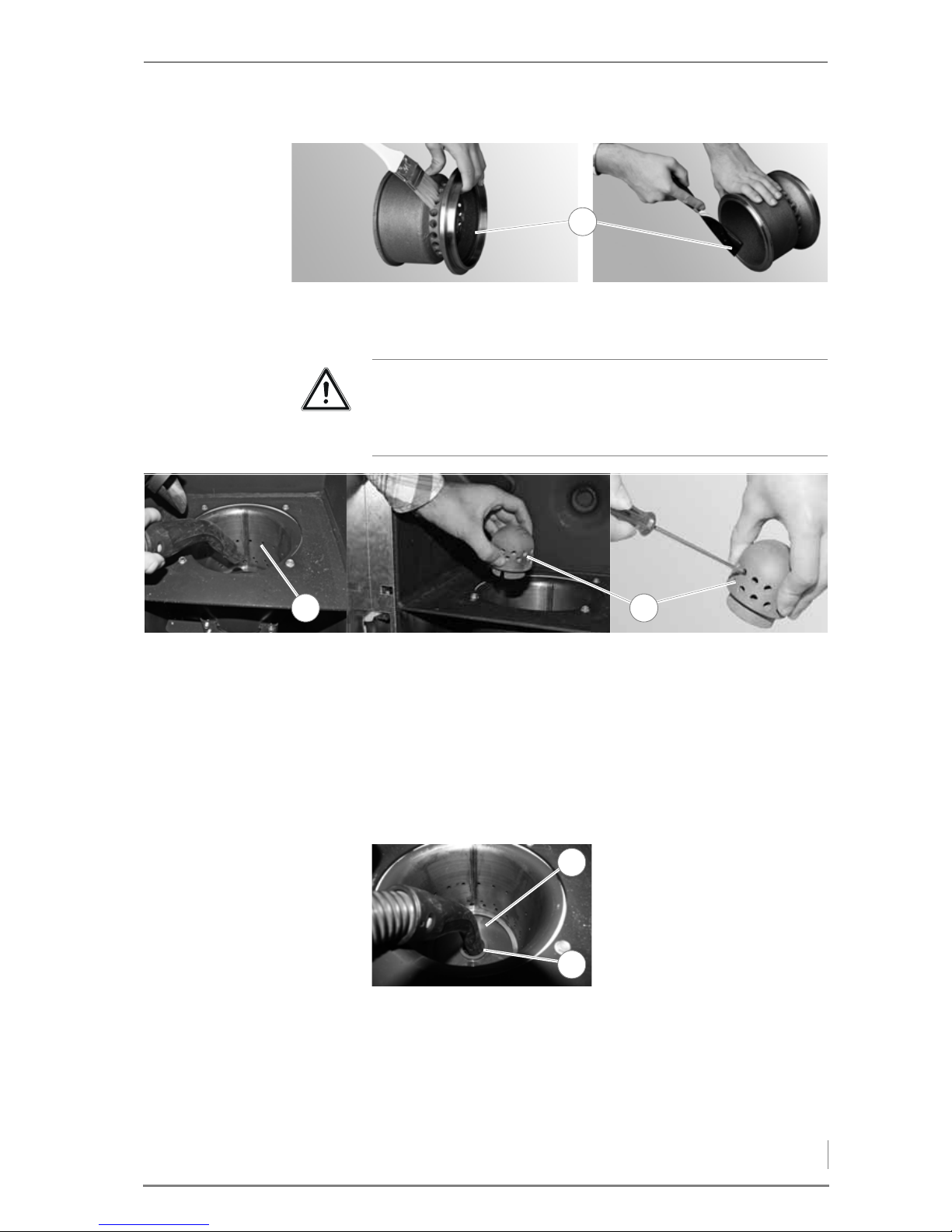
7 Cleaning and servicing the heating system – Procedure
51
9. Clean the cone (1) on all sides using a brush and remove any hard
deposits with a scraper.
10.Clean the burner pot (1) with a vacuum cleaner.
11.Make sure that the secondary air openings in the burner pot (1)
are free.
12.Take the primary air pin (2) out of the burner pot.
13.Carefully clean the primary air pin (2) and the primary air holes
with a suitable tool (such as a screwdriver).
14.Make sure that the primary air holes are free.
16.Clean the remaining combustion residues in the burner pot and
the primary air pipe (1) using a vacuum cleaner.
17.Ensure that there are no more combustion residues in the primary
air pipe since otherwise the ignition element can be damaged.
Figure 7/10 - Cleaning the cone
1
Important!
Always remove all the ash from the combustion chamber and
burner pot first. Only then can you take out the primary air pin for
cleaning.
Figure 7/11 - Cleaning the combustion chamber and primary air pin
1 2
15.Use the cleaning tool to
remove any combustion
residue from the bottom of
the burner pot (1).
Figure 7/12 - Cleaning the primary air pipe
1
2
Page 52
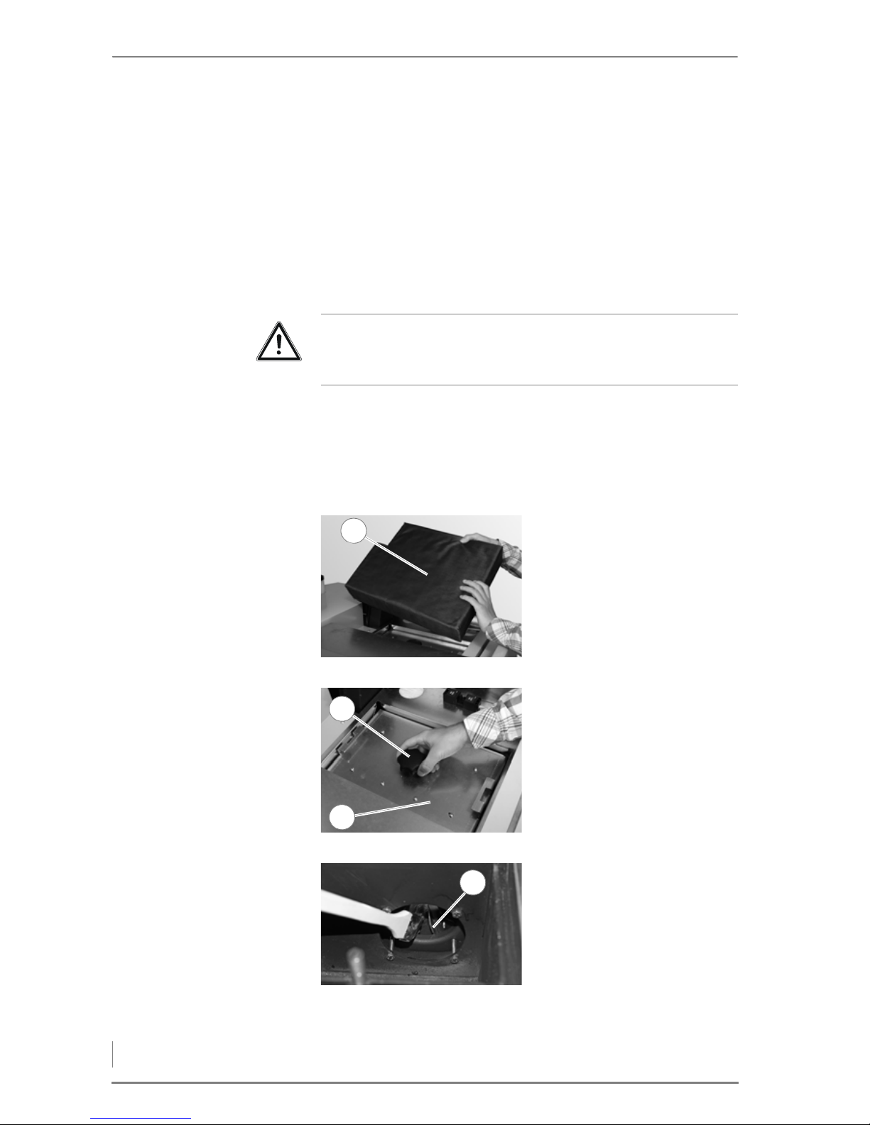
7 Cleaning and servicing the heating system – Procedure
52
18.If necessary clean the primary air pipe once again with a vacuum
cleaner.
19.Reinstall the burner pot in the reverse order.
20.Reset the cleaning prompt in the boiler control system for the
combustion chamber and burner pot.
✓ The combustion chamber and the burner pot are now clean.
CLEANING THE FLUE GAS FAN AND CLEANING SHAFT
1. Switch the heating system off.
✎ See the “HDG Control” operating manual, chapter “5 Using the
control unit”, section “5.3 Switching off the heating system”.
2. Allow the fire in the heating system to burn out and cool down.
3. Remove the top right cladding.
Important!
Observe the “Generally applicable safety instructions” in this
section.
4. Remove the insulation (1)
from the cleaning shaft lid.
Figure 7/13 - Removing the insulation
1
5. Release the star-grip screw (1)
and lift off the cleaning shaft
lid (2).
Figure 7/14 - Dismantling the cleaning shaft lid
1
2
6. Clean the fan wheel (1) with a
brush or a vacuum cleaner.
Figure 7/15 - Cleaning the fan wheel
1
Page 53
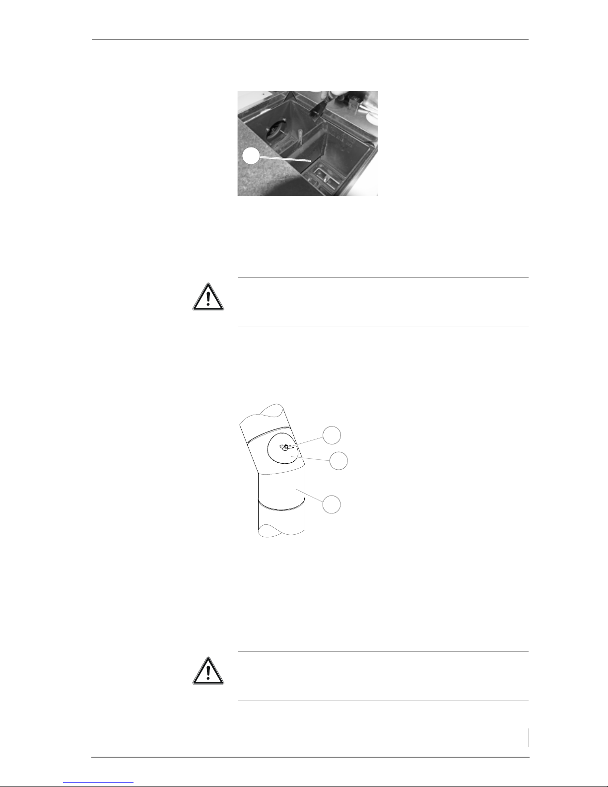
7 Cleaning and servicing the heating system – Procedure
53
✓ The flue gas fan and the cleaning shaft are now clean.
CLEANING THE FLUE GAS PIPE
1. Switch the heating system off.
✎ See the “HDG Control” operating manual, chapter “5 Using the
control unit”, section “5.3 Switching off the heating system”.
2. Allow the fire in the heating system to burn out and cool down.
7. Screw the inspection hatch (2) securely onto the flue gas pipe (3)
with the wing nut (1).
✓ The cleaning of the flue gas pipe is completed.
CHECK THE FILL LEVEL OF THE WATER TANK
7. Clean the cleaning shaft lid (1)
using a scraper.
8. Remove the flue ash in the
cleaning shaft (1) with a
vacuum cleaner.
9. Close the boiler in the reverse
order.
Figure 7/16 - Cleaning the cleaning shaft
1
Important!
Observe the “Generally applicable safety instructions” in this
section.
3. Unscrew the wing nut (1) on
the inspection hatch lid (2).
4. Remove the inspection hatch
lid (2) from the flue gas pipe
(3).
5. Check whether the flue gas
pipe (3) needs cleaning.
6. If necessary, suction the ash
out of the flue gas pipe using
a vacuum cleaner (3).
Figure 7/17 - Clean the flue gas pipe
1
2
3
Important!
Observe the “Generally applicable safety instructions” in this
section.
Page 54
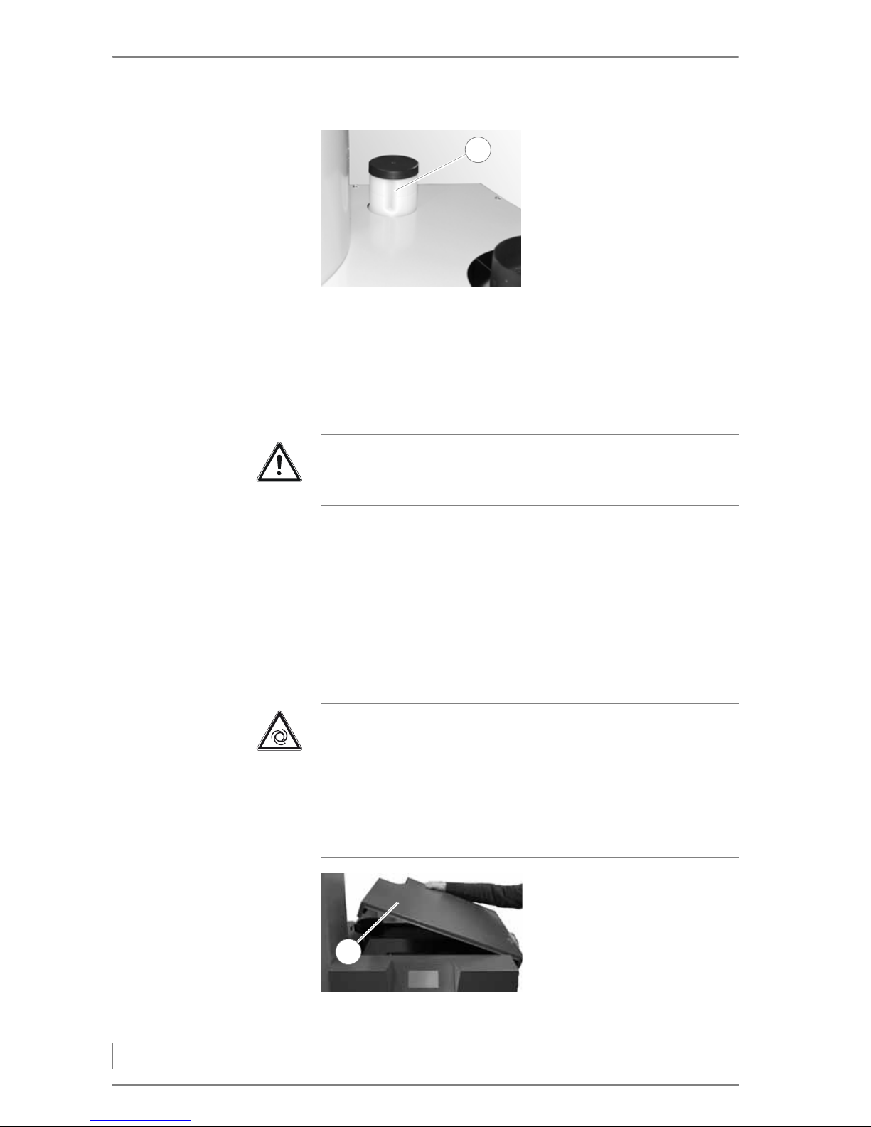
7 Cleaning and servicing the heating system – Procedure
54
✓ The fill level of the water tank has been checked.
CHECKING AND CLEANING THE RESERVOIR AND FLAP OF THE DELIVERY
UNIT
The reservoir and the flap of the delivery unit have to be cleaned
when too much dust has accumulated or there is a foreign body in
the reservoir. If no pellets can be delivered to the reservoir by the
pellet suction system, emergency manual filling is possible via the
inspection hatch.
1. Switch the heating system off.
✎ See the “HDG Control” operating manual, chapter “5 Using the
control unit”, section “5.3 Switching off the heating system”.
2. Allow the fire in the heating system to burn out and cool down.
1. Check the fill level of the
water tank (1) (volume
approx. 8 l).
✓ If the minimum fill level
indicator is not reached,
water must be added.
2. Top up the water tank (1).
Figure 7/18 - Water tank fill level
1
Important!
Observe the “Generally applicable safety instructions” in this
section.
Caution!
Risk of serious injury if the stoker auger starts up
The stoker auger can start up unexpectedly. When the inspection
hatch is open, you hands or fingers can be crushed.
Before opening the inspection hatch on the reservoir, always
disconnect the boiler from the power supply (pull out the mains
plug) and secure it against being switched on again.
3. Lift off the top right cover (1)
of the boiler.
Figure 7/19 - Removing the upper cover
1
Page 55
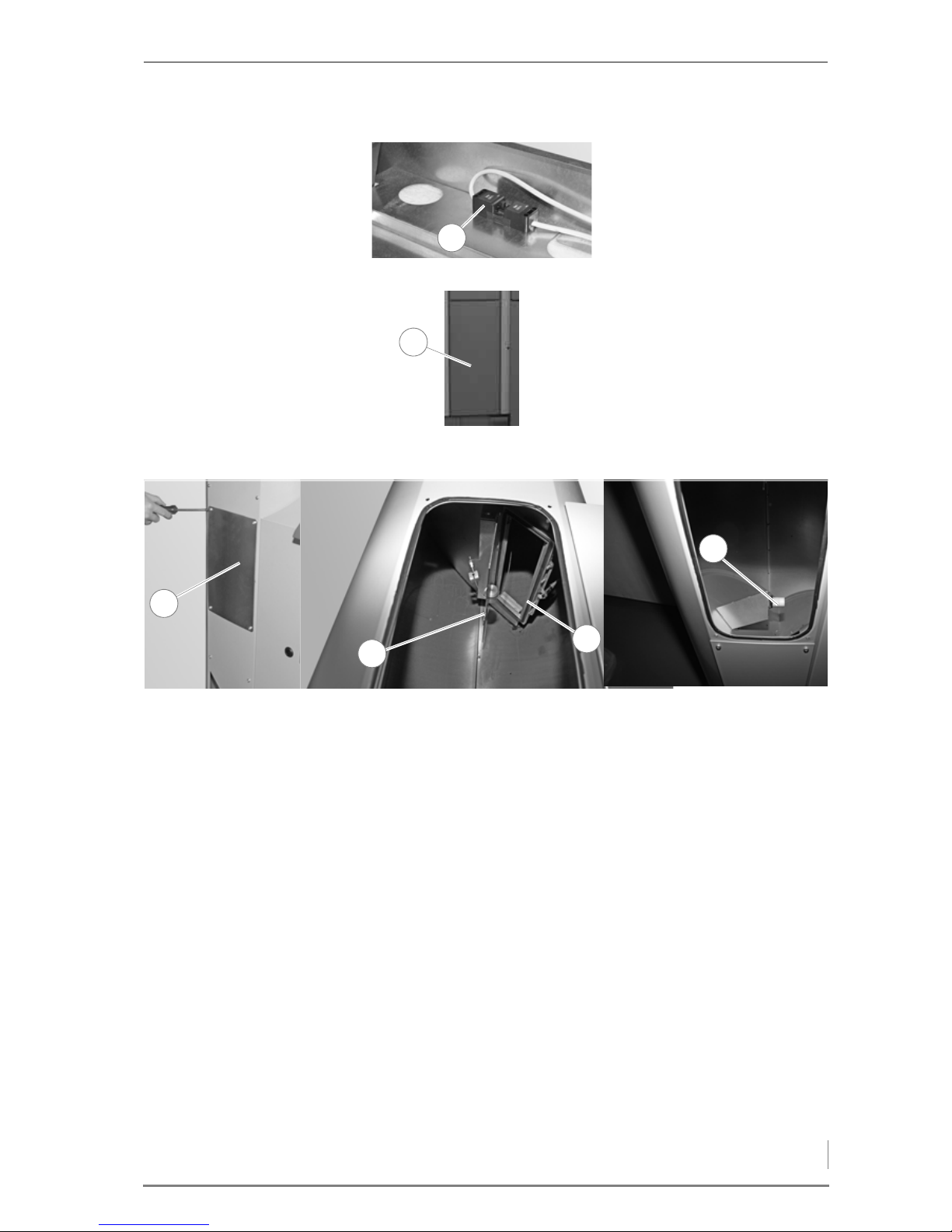
7 Cleaning and servicing the heating system – Procedure
55
6. Have a container ready for the pellets.
7. Undo the four screws of the inspection hatch (1) and remove
them.
8. Remove the pellets and dust from the reservoir.
9. Remove the dust in the on the flap (2) of the delivery unit and the
proximity switch (4) with a vacuum cleaner.
10.Check that the flap (2) moves smoothly.
11.Ensure that the entire surface of the flap (2) touches the seal (3).
4. Pull out the mains plug (1).
Figure 7/20 - Removing the mains plug
1
5. Undo the four screws and
remove the lower front
cladding (1) of the reservoir.
Figure 7/21 - Removing the lower front cladding
1
Figure 7/22 - Checking and cleaning the reservoir and flap of the delivery unit
1
4
2
3
Page 56
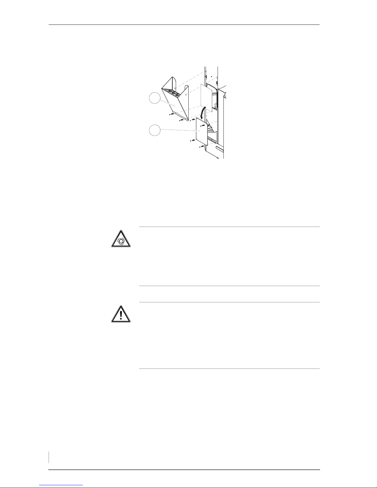
7 Cleaning and servicing the heating system – Procedure
56
EMERGENCY FILLING OF THE
RESERVOIR
15.Close the reservoir and the boiler in the reverse order.
✓ The reservoir and the flap of the delivery unit have been cleaned.
CLEANING THE PELLET STORAGE ROOM
HDG AUGER
HDG
SUCTION SYSTEM WITH
SUCTION PROBES
GENERAL INFORMATION 1. Switch the heating system off.
✎ See the “HDG Control” operating manual, chapter “5 Using the
control unit”, section “5.3 Switching off the heating system”.
2. Allow the fire in the heating system to burn out and cool down.
3. Open the access hatch of the pellet storage room.
4. Remove the wooden boards inside the access hatch.
12.Mount the inspection hatch
(2) as touch protection on the
opening for the conveyor
auger.
13.If necessary, fasten the pellet
scuttle (1) to the reservoir.
14.Fill the pellets into the
reservoir (using the pellet
scuttle (1) if necessary).
Figure 7/23 - Emergency filling
1
2
Caution!
Danger of injury from the rotating auger!
When the heating system is turned on, the auger rotates in the
pellet storage room. Hands and feet could thereby be crushed.
Switch the heating system off before you enter the pellet storage
room.
Caution!
Material compression at the suction probes
If the pellet storage room is entered, there can be material
compression in the suction probes. This can lead to the pellet
delivery being impaired.
When you enter the pellet storage room, be sure not to stand on the
pellets in the area of the suction sensors.
Page 57

7 Cleaning and servicing the heating system – Procedure
57
5. Check the pellet storage room for foreign objects and remove
them if necessary.
6. Clean the pellet storage room with a vacuum cleaner.
7. Check tha t no p ellets are swollen, if moistur e has gotten inside the
pellet storage room.
8. Close the access hatch in the reverse sequence.
✓ The pellet storage room has been cleaned.
Leading pellet suppliers recommend completely emptying the
pellet storage room every 2–3 years. When operating the heating
system with HDG suction system and suction probes, you can
deactivate the automatic changeover between the three suction
probes using the boiler control system.
✎ See chapter “6 Using the heating system”, section “Operator
level”, paragraph “Sensor changeover”.
In this way you can completely empty the fuel storage room at a
probe (that is, 1/3 of the fuel storage room) and continue heating
with the other two suction probes. If you repeat this process every
year with one of the other sensors, "renew" your entire pellet supply
every three years.
Page 58
8 Notes on dismantling and disposal – Dismantling
58
8 Notes on dismantling and
disposal
8.1 Dismantling
The heating system can be dismantled as follows.
1. Allow the fire in the boiler to burn out and cool off.
2. Switch the heating system off.
✎ See chapter “6 Using the heating system”, section “6.5 Switching
off the heating system for repair work”.
3. Switch the circuit breaker for the heating system off.
4. Disconnect the heating system from the electrical power supply.
5. Once it has cooled down, drain the heating water from the system.
6. Observe the safety regulations for personnel when disconnecting
the boiler from the heating system.
7. Dismantle the individual components of the heating system.
✓ The heating system has been dismantled.
8.2 Disposal
The following components are made of steel and can be recycled via
a local recycling centre.
• Boiler
• Cladding
• Reservoir
• Conveyor auger without motor
• Transfer station without motor
• Delivery system
• Pressure relief baffle
• Sloping floor supports
Danger!
Material damage and injury due to incorrect dismantling.
Dismantling the system requires comprehensive specialist
knowledge. If the heating system is dismantled by an untrained
person, injuries are possible.
Only allow authorised specialists to dismantle the system.
Page 59

8 Notes on dismantling and disposal – Disposal
59
The electrical components can also be recycled via a local recycling
centre.
Fibreglass, mineral wool and plastic parts such as suction hoses etc.
should be handed in to the respective waste disposal centres.
The geared motors used consist largely of materials which can be
recycled. If a geared motor cannot be handed over complete to a
suitable company for proper disposal, proceed as follows:
1. The gear oil must be drained into a suitable container.
2. The geared motor should be dismantled into its separate
components and cleaned if necessary.
3. Metal parts should be recycled.
Oily or greasy components and condensers may only be disposed
of through a specialist waste disposal centre.
Page 60

9 Declaration of Conformity
60
HDG K10 - 33 - Version 1 - de © HDG Bavaria GmbH 07/2008
9 Declaration of Conformity
EC Declaration of Conformity
in accordance with Section A of Part 1 of Annex II of the
EC Directive 2006/42 on machinery
Producer:
HDG Bavaria GmbH
Heating syst em for wood
Siemensstraße 22
D - 84323 Massing
Resident of the EC authorized to assemble the
adequate technical documentation
Stefan Holfelder
HDG Bavaria GmbH
Heating syst em for wood
Siemensstraße 22
D - 84323 Massing
Description and identification of the machinery
Product HDG pellet boiler
Type
HDG K10/15/ 21/26
/33
We definitely declare hereby that the machinery complies with each and every relevant provision of the
following EC Directives
.
2006/42/EC
2004/108/EC
Directive 2006/42/EC of the European Parliament and of the Council of 17 May 2006 on machinery,
and amending D irective 95/16/EC (recast) (1 )
Directive 2004/108/EC of the European Parliament and of the Council of 15 December 2004 on
the approximation of the laws of the Member States relating to electromagnetic compatibility and
repealing Directive 89/336/EEC
In accordance with section 2 of article 7 the applied harmonized regulations are to be found under
EN 303-5:2012
Part 5: Heating boilers for solid fuels, hand and automatically fired, nominal heat output of
up to 500 kW. Terminology, requirements, testing and marking
Massing, 02.08.2017
Place, date
Signature
Martin Eck er
CEO
Page 1/1
Page 61

10 Index
61
10 Index
A
Accumulator . . . . . . . . . . . . . . . . . . . . . . . . . . . . . . . 23
Actuator . . . . . . . . . . . . . . . . . . . . . . . . . . . . . . . . . . . . 6
Air inlet cross section . . . . . . . . . . . . . . . . . . . . . . . 16
Ash compartment . . . . . . . . . . . . . . . . . . . . . . . . . . 13
Ash container . . . . . . . . . . . . . . . . . . . . . . . . . . . . . . 13
- Emptying . . . . . . . . . . . . . . . . . . . . . . . . . . . . . 48
B
Boiler class . . . . . . . . . . . . . . . . . . . . . . . . . . . . . . . . . 16
Boiler control unit . . . . . . . . . . . . . . . . . . . . . . . . . . 14
Boiler flow
- Connection . . . . . . . . . . . . . . . . . . . . . . . . . . . 19
Boiler installation site . . . . . . . . . . . . . . . . . . . . . . 19
Boiler return
- Connection . . . . . . . . . . . . . . . . . . . . . . . . . . . 19
Burner pot . . . . . . . . . . . . . . . . . . . . . . . . . . . . . . . . . 13
- Cleaning . . . . . . . . . . . . . . . . . . . . . . . . . . . . . . 49
C
Chimney . . . . . . . . . . . . . . . . . . . . . . . . . . . . . . . . . . . 20
- Connecting . . . . . . . . . . . . . . . . . . . . . . . . . . . 39
Chimney sweep test . . . . . . . . . . . . . . . . . . . . . . . . 44
Cleaning and servicing schedule . . . . . . . . . . . . 46
Cleaning shaft
- Cleaning . . . . . . . . . . . . . . . . . . . . . . . . . . . . . . 52
Cleaning tools . . . . . . . . . . . . . . . . . . . . . . . . . . . . . 48
Combustion chamber
- Cleaning . . . . . . . . . . . . . . . . . . . . . . . . . . . . . . 49
Combustion chamber temperature sensor . . 13
Combustion process . . . . . . . . . . . . . . . . . . . . . . . 13
Commissioning the system . . . . . . . . . . . . . . . . . 41
Conveyor auger . . . . . . . . . . . . . . . . . . . . . . . . . . . . 12
D
Declaration of Conformity . . . . . . . . . . . . . . . . . . 60
Delivery system . . . . . . . . . . . . . . . . . . . . . . . . . 6, 14
Dimensions . . . . . . . . . . . . . . . . . . . . . . . . . . . . . . . . 19
DIN EN 13384-1 . . . . . . . . . . . . . . . . . . . . . . . . . . . . 20
DIN EN ISO 17225 . . . . . . . . . . . . . . . . . . . . . . . . . . 17
DINplus . . . . . . . . . . . . . . . . . . . . . . . . . . . . . . . . . . . . 17
Dismantling . . . . . . . . . . . . . . . . . . . . . . . . . . . . . . . 58
Display . . . . . . . . . . . . . . . . . . . . . . . . . . . . . . . . . . . . . 6
Disposal . . . . . . . . . . . . . . . . . . . . . . . . . . . . . . . . . . . 58
Drop chute . . . . . . . . . . . . . . . . . . . . . . . . . . . . . . . . 13
E
Efficiency . . . . . . . . . . . . . . . . . . . . . . . . . . . . . . . . . . 16
Electrical connection . . . . . . . . . . . . . . . . . . . . . . . 16
Electrical system . . . . . . . . . . . . . . . . . . . . . . . 22, 39
ENplus . . . . . . . . . . . . . . . . . . . . . . . . . . . . . . . . . . . . . 17
Expansion module EM4
- Mounting . . . . . . . . . . . . . . . . . . . . . . . . . . . . . 37
Expansion modules . . . . . . . . . . . . . . . . . . . . . . . . 37
F
Flap of the delivery unit . . . . . . . . . . . . . . . . . . . . 12
- Cleaning . . . . . . . . . . . . . . . . . . . . . . . . . . . . . . 54
Flue calculation . . . . . . . . . . . . . . . . . . . . . . . . 16, 20
Flue draught requirement . . . . . . . . . . . . . . . . . . 16
Flue gas fan
- Cleaning . . . . . . . . . . . . . . . . . . . . . . . . . . . . . . 52
Flue gas mass flow . . . . . . . . . . . . . . . . . . . . . . . . . 16
Flue gas pipe
- Cleaning . . . . . . . . . . . . . . . . . . . . . . . . . . . . . . 53
Flue gas pipe connection . . . . . . . . . . . . . . . . . . . 16
Flue gas temperature . . . . . . . . . . . . . . . . . . . . . . 16
Fuel . . . . . . . . . . . . . . . . . . . . . . . . . . . . . . . . . . . . . . . 17
G
Glossary . . . . . . . . . . . . . . . . . . . . . . . . . . . . . . . . . . . . 6
H
HDG Control . . . . . . . . . . . . . . . . . . . . . . . . . . . 14, 43
Heating system
- Switching off . . . . . . . . . . . . . . . . . . . . . . . . . . 45
I
Installing the boiler . . . . . . . . . . . . . . . . . . . . . . . . . 28
L
Level indicator . . . . . . . . . . . . . . . . . . . . . . . . . . . . . 12
Lightning/surge protection . . . . . . . . . . . . . . . . . 22
Low voltage directive . . . . . . . . . . . . . . . . . . . . . . 22
M
Minimum clearances . . . . . . . . . . . . . . . . . . . . . . . 18
N
Nominal thermal power . . . . . . . . . . . . . . . . . . . . 16
O
Operating pressure . . . . . . . . . . . . . . . . . . . . . . . . . 16
Original state on delivery . . . . . . . . . . . . . . . 25, 26
P
Pellet storage room
- Cleaning . . . . . . . . . . . . . . . . . . . . . . . . . . . . . . 56
Page 62

10 Index
62
HDG Compact 25/35 - Version 2 - de © HDG Bavaria GmbH Oktober 2007
- Filling . . . . . . . . . . . . . . . . . . . . . . . . . . . . . . . . . 43
- Safety instructions . . . . . . . . . . . . . . . . . . . . . 11
Pellet suction system . . . . . . . . . . . . . . . . . . . . 6, 15
Pellets . . . . . . . . . . . . . . . . . . . . . . . . . . . . . . . . . . . . . . 6
Pipe dimensions . . . . . . . . . . . . . . . . . . . . . . . . . . . 16
Primary air pin . . . . . . . . . . . . . . . . . . . . . . . . . . . . . 13
Proper and improper operation . . . . . . . . . . . . . . 7
R
Reservoir . . . . . . . . . . . . . . . . . . . . . . . . . . . . . . . 6, 12
- Cleaning . . . . . . . . . . . . . . . . . . . . . . . . . . . . . . 54
- Filling . . . . . . . . . . . . . . . . . . . . . . . . . . . . . . . . . 44
Residual risks . . . . . . . . . . . . . . . . . . . . . . . . . . . . . . . 8
Return temperature . . . . . . . . . . . . . . . . . . . . . . . . 23
Return temperature, minimum . . . . . . . . . . . . . 16
Room sizes . . . . . . . . . . . . . . . . . . . . . . . . . . . . . . . . . 18
running time . . . . . . . . . . . . . . . . . . . . . . . . . . . . . . . 12
S
Safety devices . . . . . . . . . . . . . . . . . . . . . . . . . . . . . . 23
Scope of delivery . . . . . . . . . . . . . . . . . . . . . . . . . . . 24
Sensor . . . . . . . . . . . . . . . . . . . . . . . . . . . . . . . . . . . . . . 6
Sound pressure level . . . . . . . . . . . . . . . . . . . . . . . 16
Spare parts . . . . . . . . . . . . . . . . . . . . . . . . . . . . . . . . 46
Supply . . . . . . . . . . . . . . . . . . . . . . . . . . . . . . . . . . . . . 26
Supply temperature, maximum . . . . . . . . . . . . . 16
T
Technical data . . . . . . . . . . . . . . . . . . . . . . . . . . . . . 16
V
VDI 2035 . . . . . . . . . . . . . . . . . . . . . . . . . . . . . . . 23, 40
VDI 3464 . . . . . . . . . . . . . . . . . . . . . . . . . . . . . . . . . . . 11
W
Warnings and safety symbols . . . . . . . . . . . . . . . . 9
Water . . . . . . . . . . . . . . . . . . . . . . . . . . . . . . . . . . 22, 40
Water capacity . . . . . . . . . . . . . . . . . . . . . . . . . . . . . 16
Water tank
- Checking the fill level . . . . . . . . . . . . . . . . . . 53
Weight . . . . . . . . . . . . . . . . . . . . . . . . . . . . . . . . . . . . 16
Page 63

Page 64

HDG Bavaria GmbH
Heizsysteme für Holz
Siemensstraße 22
D-84323 Massing
Tel. +49(0)8724/ 897-0
[email protected]
www.hdg-bavaria.com
Art.Nr: 9980001814 - V 05 - en - 08/2017 Translation of the original operating instructions
 Loading...