

Page 1

hdg-bavaria.com
HDG Compact 99 - 200
Operation Manual
Page 2

Page 3

Operation Manual HDG Compact 99 - 200 - Content
3
Content
1 Notes on this manual . . . . . . . . . . . . . . . . . . . . . . . . . . . . . . . . . . . . . . . . . . . . . . . . . . . . . . . .8
1.1 Introduction. . . . . . . . . . . . . . . . . . . . . . . . . . . . . . . . . . . . . . . . . . . . . . . . . . . . . . . . . . . . . . . . .8
1.2 Structure of the operating manual . . . . . . . . . . . . . . . . . . . . . . . . . . . . . . . . . . . . . . . . . . .9
1.3 Glossary. . . . . . . . . . . . . . . . . . . . . . . . . . . . . . . . . . . . . . . . . . . . . . . . . . . . . . . . . . . . . . . . . . . .10
2 Safety instructions. . . . . . . . . . . . . . . . . . . . . . . . . . . . . . . . . . . . . . . . . . . . . . . . . . . . . . . . . .11
2.1 Intended use . . . . . . . . . . . . . . . . . . . . . . . . . . . . . . . . . . . . . . . . . . . . . . . . . . . . . . . . . . . . . . .11
Basic system design principles. . . . . . . . . . . . . . . . . . . . . . . . . . . . . . . . . . . . . . . . . . . . .11
Basic principles on the content of the operating manual . . . . . . . . . . . . . . . . . . .11
Proper and improper manner of operation. . . . . . . . . . . . . . . . . . . . . . . . . . . . . . . . .11
2.2 Residual risks. . . . . . . . . . . . . . . . . . . . . . . . . . . . . . . . . . . . . . . . . . . . . . . . . . . . . . . . . . . . . . .12
2.3 Warnings and safety symbols used . . . . . . . . . . . . . . . . . . . . . . . . . . . . . . . . . . . . . . . . . .14
2.4 Duty of information . . . . . . . . . . . . . . . . . . . . . . . . . . . . . . . . . . . . . . . . . . . . . . . . . . . . . . . .15
3 Mode of operation . . . . . . . . . . . . . . . . . . . . . . . . . . . . . . . . . . . . . . . . . . . . . . . . . . . . . . . . .16
3.1 Overview. . . . . . . . . . . . . . . . . . . . . . . . . . . . . . . . . . . . . . . . . . . . . . . . . . . . . . . . . . . . . . . . . . .16
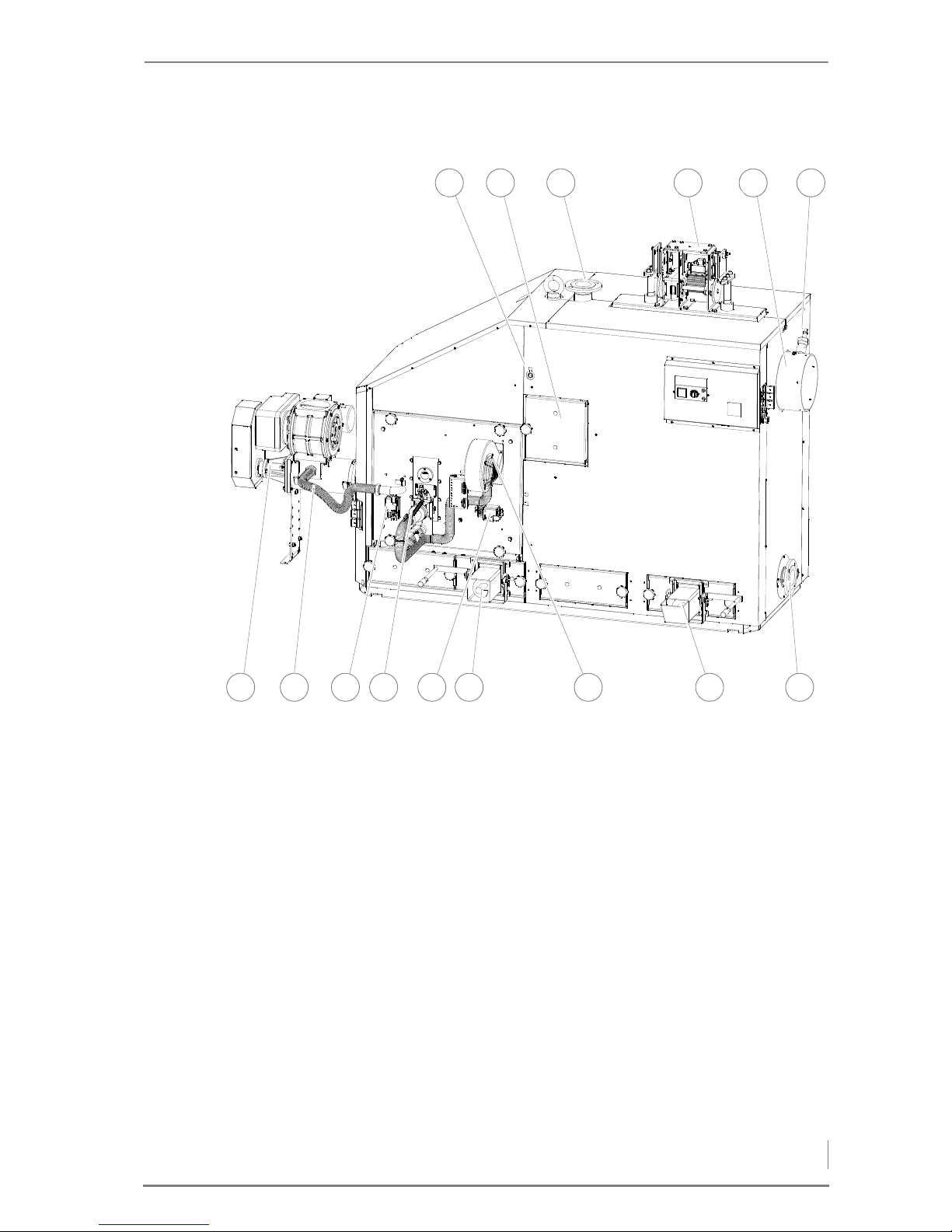
Front side of HDG Compact 99/100/105/115 . . . . . . . . . . . . . . . . . . . . . . . . . . . . . . .17
Back side of HDG Compact 99/100/105/115. . . . . . . . . . . . . . . . . . . . . . . . . . . . . . . .18
Front side of HDG Compact 150/194/199/200. . . . . . . . . . . . . . . . . . . . . . . . . . . . . .19
Back side of HDG Compact 150/194/199/200 . . . . . . . . . . . . . . . . . . . . . . . . . . . . . .20
3.2 Functional description. . . . . . . . . . . . . . . . . . . . . . . . . . . . . . . . . . . . . . . . . . . . . . . . . . . . . .21
Combustion process . . . . . . . . . . . . . . . . . . . . . . . . . . . . . . . . . . . . . . . . . . . . . . . . . . . . . .21
Delivery system . . . . . . . . . . . . . . . . . . . . . . . . . . . . . . . . . . . . . . . . . . . . . . . . . . . . . . . . . . .22
HDG Control . . . . . . . . . . . . . . . . . . . . . . . . . . . . . . . . . . . . . . . . . . . . . . . . . . . . . . . . . . . . . .22
Control modes. . . . . . . . . . . . . . . . . . . . . . . . . . . . . . . . . . . . . . . . . . . . . . . . . . . . . . . . . . . .23
3.3 Technical data. . . . . . . . . . . . . . . . . . . . . . . . . . . . . . . . . . . . . . . . . . . . . . . . . . . . . . . . . . . . . .24
3.4 Fuel quality requirements. . . . . . . . . . . . . . . . . . . . . . . . . . . . . . . . . . . . . . . . . . . . . . . . . . .26
Permissible fuel . . . . . . . . . . . . . . . . . . . . . . . . . . . . . . . . . . . . . . . . . . . . . . . . . . . . . . . . . . .26
Wood chips . . . . . . . . . . . . . . . . . . . . . . . . . . . . . . . . . . . . . . . . . . . . . . . . . . . . . . . . . . . . . .27
Wood pellets . . . . . . . . . . . . . . . . . . . . . . . . . . . . . . . . . . . . . . . . . . . . . . . . . . . . . . . . . . . . .28
Recommended fuel . . . . . . . . . . . . . . . . . . . . . . . . . . . . . . . . . . . . . . . . . . . . . . . . . . . . . . .29
4 Planning and installation . . . . . . . . . . . . . . . . . . . . . . . . . . . . . . . . . . . . . . . . . . . . . . . . . . .31
4.1 Planning the heating system. . . . . . . . . . . . . . . . . . . . . . . . . . . . . . . . . . . . . . . . . . . . . . . .31
Required room sizes and minimum spacing. . . . . . . . . . . . . . . . . . . . . . . . . . . . . . . .31
Dimensions. . . . . . . . . . . . . . . . . . . . . . . . . . . . . . . . . . . . . . . . . . . . . . . . . . . . . . . . . . . . . . .32
Boiler room . . . . . . . . . . . . . . . . . . . . . . . . . . . . . . . . . . . . . . . . . . . . . . . . . . . . . . . . . . . . . . .32
Fuel bunker. . . . . . . . . . . . . . . . . . . . . . . . . . . . . . . . . . . . . . . . . . . . . . . . . . . . . . . . . . . . . . .33
Delivery system versions . . . . . . . . . . . . . . . . . . . . . . . . . . . . . . . . . . . . . . . . . . . . . . . . . .34
4.2 Connections . . . . . . . . . . . . . . . . . . . . . . . . . . . . . . . . . . . . . . . . . . . . . . . . . . . . . . . . . . . . . . .36
Chimney . . . . . . . . . . . . . . . . . . . . . . . . . . . . . . . . . . . . . . . . . . . . . . . . . . . . . . . . . . . . . . . . .36
Electrical system . . . . . . . . . . . . . . . . . . . . . . . . . . . . . . . . . . . . . . . . . . . . . . . . . . . . . . . . . .38
Water. . . . . . . . . . . . . . . . . . . . . . . . . . . . . . . . . . . . . . . . . . . . . . . . . . . . . . . . . . . . . . . . . . . . .39
Dimensions of the flue pipe side of the HDG Compact 99 - 115 . . . . . . . . . . . . .41
Dimensions of the back side of HDG Compact 99 - 115 . . . . . . . . . . . . . . . . . . . . .42
Page 4

Operation Manual HDG Compact 99 - 200 - Content
4
Dimensions of the flue pipe side of the HDG Compact 150 - 200 . . . . . . . . . . . 43
Dimensions of the back side of HDG Compact 150 - 200 . . . . . . . . . . . . . . . . . . . 44
4.3 Scope of delivery . . . . . . . . . . . . . . . . . . . . . . . . . . . . . . . . . . . . . . . . . . . . . . . . . . . . . . . . . . 45
4.4 Installing the heating system . . . . . . . . . . . . . . . . . . . . . . . . . . . . . . . . . . . . . . . . . . . . . . 46
Requirements. . . . . . . . . . . . . . . . . . . . . . . . . . . . . . . . . . . . . . . . . . . . . . . . . . . . . . . . . . . . 46
Placing the boiler . . . . . . . . . . . . . . . . . . . . . . . . . . . . . . . . . . . . . . . . . . . . . . . . . . . . . . . . 47
Installing the feeding system . . . . . . . . . . . . . . . . . . . . . . . . . . . . . . . . . . . . . . . . . . . . . 47
Attaching the pressure equalisation hose . . . . . . . . . . . . . . . . . . . . . . . . . . . . . . . . . 49
Installing ash container(s) . . . . . . . . . . . . . . . . . . . . . . . . . . . . . . . . . . . . . . . . . . . . . . . . 50
Installing the central ash removal system . . . . . . . . . . . . . . . . . . . . . . . . . . . . . . . . . 51
Fitting the buffer probe . . . . . . . . . . . . . . . . . . . . . . . . . . . . . . . . . . . . . . . . . . . . . . . . . . 54
Installing the EMD-C 215 Exclusiv control cabinet . . . . . . . . . . . . . . . . . . . . . . . . . 55
Connecting the chimney . . . . . . . . . . . . . . . . . . . . . . . . . . . . . . . . . . . . . . . . . . . . . . . . . 55
4.5 Delivery system . . . . . . . . . . . . . . . . . . . . . . . . . . . . . . . . . . . . . . . . . . . . . . . . . . . . . . . . . . . 55
General information. . . . . . . . . . . . . . . . . . . . . . . . . . . . . . . . . . . . . . . . . . . . . . . . . . . . . . 55
HDG hose junction . . . . . . . . . . . . . . . . . . . . . . . . . . . . . . . . . . . . . . . . . . . . . . . . . . . . . . . 56
4.6 HDG cyclone dust extractor . . . . . . . . . . . . . . . . . . . . . . . . . . . . . . . . . . . . . . . . . . . . . . . . 60
4.7 Electrical system. . . . . . . . . . . . . . . . . . . . . . . . . . . . . . . . . . . . . . . . . . . . . . . . . . . . . . . . . . . 60
4.8 Water . . . . . . . . . . . . . . . . . . . . . . . . . . . . . . . . . . . . . . . . . . . . . . . . . . . . . . . . . . . . . . . . . . . . . 60
4.9 Thermal safety device . . . . . . . . . . . . . . . . . . . . . . . . . . . . . . . . . . . . . . . . . . . . . . . . . . . . . 61
4.10 Hydraulic system . . . . . . . . . . . . . . . . . . . . . . . . . . . . . . . . . . . . . . . . . . . . . . . . . . . . . . . . . . 63
5 Commissioning the system . . . . . . . . . . . . . . . . . . . . . . . . . . . . . . . . . . . . . . . . . . . . . . . . 64
5.1 Requirements . . . . . . . . . . . . . . . . . . . . . . . . . . . . . . . . . . . . . . . . . . . . . . . . . . . . . . . . . . . . . 64
5.2 Procedure . . . . . . . . . . . . . . . . . . . . . . . . . . . . . . . . . . . . . . . . . . . . . . . . . . . . . . . . . . . . . . . . . 65
Switching on the heating system . . . . . . . . . . . . . . . . . . . . . . . . . . . . . . . . . . . . . . . . . 65
Setting the display language . . . . . . . . . . . . . . . . . . . . . . . . . . . . . . . . . . . . . . . . . . . . . 65
Checking the actuators in manual operation . . . . . . . . . . . . . . . . . . . . . . . . . . . . . . 65
Filling the ash accumulation bin . . . . . . . . . . . . . . . . . . . . . . . . . . . . . . . . . . . . . . . . . . 67
Filling the fuel bunker . . . . . . . . . . . . . . . . . . . . . . . . . . . . . . . . . . . . . . . . . . . . . . . . . . . . 68
Adapting parameters . . . . . . . . . . . . . . . . . . . . . . . . . . . . . . . . . . . . . . . . . . . . . . . . . . . . 68
6 Using the heating system . . . . . . . . . . . . . . . . . . . . . . . . . . . . . . . . . . . . . . . . . . . . . . . . . . 69
6.1 Overview of the controls and display components. . . . . . . . . . . . . . . . . . . . . . . . . . 69
Main switch. . . . . . . . . . . . . . . . . . . . . . . . . . . . . . . . . . . . . . . . . . . . . . . . . . . . . . . . . . . . . . 69
Emergency stop . . . . . . . . . . . . . . . . . . . . . . . . . . . . . . . . . . . . . . . . . . . . . . . . . . . . . . . . . 69
Additional controls. . . . . . . . . . . . . . . . . . . . . . . . . . . . . . . . . . . . . . . . . . . . . . . . . . . . . . . 69
Control cabinet model EMD-C 215 Exclusiv . . . . . . . . . . . . . . . . . . . . . . . . . . . . . . . 70
HDG Controlunit . . . . . . . . . . . . . . . . . . . . . . . . . . . . . . . . . . . . . . . . . . . . . . . . . . . . . . . . . 71
6.2 Switching on the heating system. . . . . . . . . . . . . . . . . . . . . . . . . . . . . . . . . . . . . . . . . . . 72
6.3 Switching off the heating system . . . . . . . . . . . . . . . . . . . . . . . . . . . . . . . . . . . . . . . . . . 73
6.4 Operating statuses . . . . . . . . . . . . . . . . . . . . . . . . . . . . . . . . . . . . . . . . . . . . . . . . . . . . . . . . 73
6.5 Calling up information, selecting and modifying parameters . . . . . . . . . . . . . . . . 75
6.6 ON/OFF menu. . . . . . . . . . . . . . . . . . . . . . . . . . . . . . . . . . . . . . . . . . . . . . . . . . . . . . . . . . . . . 77
Procedure . . . . . . . . . . . . . . . . . . . . . . . . . . . . . . . . . . . . . . . . . . . . . . . . . . . . . . . . . . . . . . . 77
Setting the base load / peak load boiler . . . . . . . . . . . . . . . . . . . . . . . . . . . . . . . . . . 77
Setting operating times . . . . . . . . . . . . . . . . . . . . . . . . . . . . . . . . . . . . . . . . . . . . . . . . . . 78
Setting the control, boiler activation, ignition and Lambda Stop . . . . . . . . . . . 80
Adjusting the ash removal setting . . . . . . . . . . . . . . . . . . . . . . . . . . . . . . . . . . . . . . . . 82
Page 5

Operation Manual HDG Compact 99 - 200 - Content
5
Changing the cleaning system setting . . . . . . . . . . . . . . . . . . . . . . . . . . . . . . . . . . . . .82
Modifying the dust removal setting . . . . . . . . . . . . . . . . . . . . . . . . . . . . . . . . . . . . . . .83
Modifying the extraction setting . . . . . . . . . . . . . . . . . . . . . . . . . . . . . . . . . . . . . . . . . .84
Modifying the pellet vacuum delivery system setting . . . . . . . . . . . . . . . . . . . . . .84
Modifying the moving floor setting. . . . . . . . . . . . . . . . . . . . . . . . . . . . . . . . . . . . . . . .85
6.7 °C/QUANTITY menu . . . . . . . . . . . . . . . . . . . . . . . . . . . . . . . . . . . . . . . . . . . . . . . . . . . . . . . .86
Procedure . . . . . . . . . . . . . . . . . . . . . . . . . . . . . . . . . . . . . . . . . . . . . . . . . . . . . . . . . . . . . . . .86
Viewing flue gas temperature . . . . . . . . . . . . . . . . . . . . . . . . . . . . . . . . . . . . . . . . . . . . .86
Setting the boiler supply and return temperature . . . . . . . . . . . . . . . . . . . . . . . . . .87
Reading values from the controller . . . . . . . . . . . . . . . . . . . . . . . . . . . . . . . . . . . . . . . .87
Fixed value - Setting the material and air quantity. . . . . . . . . . . . . . . . . . . . . . . . . .87
Selecting a material type . . . . . . . . . . . . . . . . . . . . . . . . . . . . . . . . . . . . . . . . . . . . . . . . . .88
Defining the switch on/off times for the boiler . . . . . . . . . . . . . . . . . . . . . . . . . . . . .88
Integrating the peak load boiler . . . . . . . . . . . . . . . . . . . . . . . . . . . . . . . . . . . . . . . . . . .89
Peak load boiler monitoring . . . . . . . . . . . . . . . . . . . . . . . . . . . . . . . . . . . . . . . . . . . . . . .90
Entering the combustion chamber temperature setting . . . . . . . . . . . . . . . . . . . .90
Entering material and temperature settings. . . . . . . . . . . . . . . . . . . . . . . . . . . . . . . .91
Entering the primary air setting . . . . . . . . . . . . . . . . . . . . . . . . . . . . . . . . . . . . . . . . . . .91
Entering the residual oxygen setting . . . . . . . . . . . . . . . . . . . . . . . . . . . . . . . . . . . . . .92
Entering the secondary air setting . . . . . . . . . . . . . . . . . . . . . . . . . . . . . . . . . . . . . . . . .92
Adapting the material quantity/O2 . . . . . . . . . . . . . . . . . . . . . . . . . . . . . . . . . . . . . . . .93
Setting underpressure control values . . . . . . . . . . . . . . . . . . . . . . . . . . . . . . . . . . . . . .94
6.8 TIME menu . . . . . . . . . . . . . . . . . . . . . . . . . . . . . . . . . . . . . . . . . . . . . . . . . . . . . . . . . . . . . . . . .94
Procedure . . . . . . . . . . . . . . . . . . . . . . . . . . . . . . . . . . . . . . . . . . . . . . . . . . . . . . . . . . . . . . . .94
Setting the filling, ignition and fan activation . . . . . . . . . . . . . . . . . . . . . . . . . . . . . .95
Setting pre-air, heating up and burning out. . . . . . . . . . . . . . . . . . . . . . . . . . . . . . . .95
Setting the ash removal and ember sustaining functions . . . . . . . . . . . . . . . . . . .95
Setting the cleaning function. . . . . . . . . . . . . . . . . . . . . . . . . . . . . . . . . . . . . . . . . . . . . .96
Setting filling delay of dosage tank . . . . . . . . . . . . . . . . . . . . . . . . . . . . . . . . . . . . . . . .96
Setting filling delay of dosage transition . . . . . . . . . . . . . . . . . . . . . . . . . . . . . . . . . . .97
Setting the moving floor delivery system . . . . . . . . . . . . . . . . . . . . . . . . . . . . . . . . . .97
Setting the agitator . . . . . . . . . . . . . . . . . . . . . . . . . . . . . . . . . . . . . . . . . . . . . . . . . . . . . . .98
Setting the peak load boiler . . . . . . . . . . . . . . . . . . . . . . . . . . . . . . . . . . . . . . . . . . . . . . .98
Setting the cycles of the pellet auger . . . . . . . . . . . . . . . . . . . . . . . . . . . . . . . . . . . . . .98
Setting the hopper extraction system. . . . . . . . . . . . . . . . . . . . . . . . . . . . . . . . . . . . . .99
Hopper extraction system - setting additional parameters. . . . . . . . . . . . . . . . . .99
Central ash removal system - setting lag time . . . . . . . . . . . . . . . . . . . . . . . . . . . . 100
Service messages - setting reminder time. . . . . . . . . . . . . . . . . . . . . . . . . . . . . . . . 100
Main cleaning - setting times . . . . . . . . . . . . . . . . . . . . . . . . . . . . . . . . . . . . . . . . . . . . 101
Setting the day, date and time. . . . . . . . . . . . . . . . . . . . . . . . . . . . . . . . . . . . . . . . . . . 101
6.9 MANUAL menu. . . . . . . . . . . . . . . . . . . . . . . . . . . . . . . . . . . . . . . . . . . . . . . . . . . . . . . . . . . 102
Procedure . . . . . . . . . . . . . . . . . . . . . . . . . . . . . . . . . . . . . . . . . . . . . . . . . . . . . . . . . . . . . . 102
Combustion air and ignition fan . . . . . . . . . . . . . . . . . . . . . . . . . . . . . . . . . . . . . . . . . 103
Ash removal, main cleaning, dust removal and cleaning system . . . . . . . . . . 103
Return pump and return mixing valve . . . . . . . . . . . . . . . . . . . . . . . . . . . . . . . . . . . 103
Feeding and dosage . . . . . . . . . . . . . . . . . . . . . . . . . . . . . . . . . . . . . . . . . . . . . . . . . . . . 104
Feeding, dosage and delivery system . . . . . . . . . . . . . . . . . . . . . . . . . . . . . . . . . . . . 104
Feeding, metering, vacuum fan and delivery system . . . . . . . . . . . . . . . . . . . . . 105
Hose junction and pellet auger . . . . . . . . . . . . . . . . . . . . . . . . . . . . . . . . . . . . . . . . . . 105
Feeding, metering and lateral auger . . . . . . . . . . . . . . . . . . . . . . . . . . . . . . . . . . . . . 105
Page 6

Operation Manual HDG Compact 99 - 200 - Content
6
Moving floor . . . . . . . . . . . . . . . . . . . . . . . . . . . . . . . . . . . . . . . . . . . . . . . . . . . . . . . . . . . . 106
6.10 SERVICE menu. . . . . . . . . . . . . . . . . . . . . . . . . . . . . . . . . . . . . . . . . . . . . . . . . . . . . . . . . . . . 106
Procedure . . . . . . . . . . . . . . . . . . . . . . . . . . . . . . . . . . . . . . . . . . . . . . . . . . . . . . . . . . . . . . 106
Chimney sweep test . . . . . . . . . . . . . . . . . . . . . . . . . . . . . . . . . . . . . . . . . . . . . . . . . . . . 108
Operating hours counter . . . . . . . . . . . . . . . . . . . . . . . . . . . . . . . . . . . . . . . . . . . . . . . . 108
Setting reverse feeding and ignition temperature . . . . . . . . . . . . . . . . . . . . . . . . 109
Setting the boiler overheating temperature or hysteresis, minimum return
temperature and combustion chamber stop temperature . . . . . . . . . . . . . . . . 110
Modifying the dosage pause min. or impulse min. and feed system lag time or
feed system lead time parameters . . . . . . . . . . . . . . . . . . . . . . . . . . . . . . . . . . . . . . . 110
Ignition fan . . . . . . . . . . . . . . . . . . . . . . . . . . . . . . . . . . . . . . . . . . . . . . . . . . . . . . . . . . . . . 111
Fuel quantity 1st Modifying filling and air start setting . . . . . . . . . . . . . . . . . . . 111
Ash removal system minimum pause . . . . . . . . . . . . . . . . . . . . . . . . . . . . . . . . . . . . 112
Testing servo motors for air control units . . . . . . . . . . . . . . . . . . . . . . . . . . . . . . . . 112
Calibrating the lambda sensor. . . . . . . . . . . . . . . . . . . . . . . . . . . . . . . . . . . . . . . . . . . 112
Flue gas temperature . . . . . . . . . . . . . . . . . . . . . . . . . . . . . . . . . . . . . . . . . . . . . . . . . . . 113
Underpressure control . . . . . . . . . . . . . . . . . . . . . . . . . . . . . . . . . . . . . . . . . . . . . . . . . . 114
Setting chimney sweep test . . . . . . . . . . . . . . . . . . . . . . . . . . . . . . . . . . . . . . . . . . . . . 114
Setting interface RS485 . . . . . . . . . . . . . . . . . . . . . . . . . . . . . . . . . . . . . . . . . . . . . . . . . 115
Modbus RTU - setting web server . . . . . . . . . . . . . . . . . . . . . . . . . . . . . . . . . . . . . . . . 116
Modbus RTU - setting DDC . . . . . . . . . . . . . . . . . . . . . . . . . . . . . . . . . . . . . . . . . . . . . . 116
Setting Profibus DP- DDC . . . . . . . . . . . . . . . . . . . . . . . . . . . . . . . . . . . . . . . . . . . . . . . 116
Entering password . . . . . . . . . . . . . . . . . . . . . . . . . . . . . . . . . . . . . . . . . . . . . . . . . . . . . . 117
Resetting parameters to the factory default . . . . . . . . . . . . . . . . . . . . . . . . . . . . . . 117
6.11 INFO menu. . . . . . . . . . . . . . . . . . . . . . . . . . . . . . . . . . . . . . . . . . . . . . . . . . . . . . . . . . . . . . . 118
6.12 Filling the fuel bunker . . . . . . . . . . . . . . . . . . . . . . . . . . . . . . . . . . . . . . . . . . . . . . . . . . . . 118
Requirements. . . . . . . . . . . . . . . . . . . . . . . . . . . . . . . . . . . . . . . . . . . . . . . . . . . . . . . . . . . 118
Procedure for filling with wood fuel products . . . . . . . . . . . . . . . . . . . . . . . . . . . . 119
Procedure for filling of pellets . . . . . . . . . . . . . . . . . . . . . . . . . . . . . . . . . . . . . . . . . . . 119
6.13 Performing the chimney sweep test. . . . . . . . . . . . . . . . . . . . . . . . . . . . . . . . . . . . . . . 119
Before the test . . . . . . . . . . . . . . . . . . . . . . . . . . . . . . . . . . . . . . . . . . . . . . . . . . . . . . . . . . 120
During the test . . . . . . . . . . . . . . . . . . . . . . . . . . . . . . . . . . . . . . . . . . . . . . . . . . . . . . . . . 120
7 Cleaning and servicing the heating system . . . . . . . . . . . . . . . . . . . . . . . . . . . . . . . . 122
7.1 Cleaning and maintenance schedule . . . . . . . . . . . . . . . . . . . . . . . . . . . . . . . . . . . . . . 122
7.2 Procedure . . . . . . . . . . . . . . . . . . . . . . . . . . . . . . . . . . . . . . . . . . . . . . . . . . . . . . . . . . . . . . . . 123
Generally applicable safety instructions. . . . . . . . . . . . . . . . . . . . . . . . . . . . . . . . . . 123
Cleaning tools . . . . . . . . . . . . . . . . . . . . . . . . . . . . . . . . . . . . . . . . . . . . . . . . . . . . . . . . . . 124
Checking and cleaning the stepped grate . . . . . . . . . . . . . . . . . . . . . . . . . . . . . . . 124
Checking and emptying the ash container . . . . . . . . . . . . . . . . . . . . . . . . . . . . . . . 125
Lubricating the feeding system. . . . . . . . . . . . . . . . . . . . . . . . . . . . . . . . . . . . . . . . . . 128
Checking the drive chains . . . . . . . . . . . . . . . . . . . . . . . . . . . . . . . . . . . . . . . . . . . . . . . 128
Cleaning the control unit. . . . . . . . . . . . . . . . . . . . . . . . . . . . . . . . . . . . . . . . . . . . . . . . 132
Check and clean the cleaning shaft and turbulators . . . . . . . . . . . . . . . . . . . . . . 132
Checking and cleaning the ignition fan . . . . . . . . . . . . . . . . . . . . . . . . . . . . . . . . . . 137
Checking and cleaning the lambda sensor . . . . . . . . . . . . . . . . . . . . . . . . . . . . . . 139
Inspecting and cleaning the flue pipe. . . . . . . . . . . . . . . . . . . . . . . . . . . . . . . . . . . . 140
Checking and cleaning the ash removal system . . . . . . . . . . . . . . . . . . . . . . . . . . 141
Checking and cleaning the pressure equalisation hose . . . . . . . . . . . . . . . . . . . 142
Checking the fill level indicator . . . . . . . . . . . . . . . . . . . . . . . . . . . . . . . . . . . . . . . . . . 143
Page 7

Operation Manual HDG Compact 99 - 200 - Content
7
Checking the plug contacts . . . . . . . . . . . . . . . . . . . . . . . . . . . . . . . . . . . . . . . . . . . . . 145
Inspecting the fuel bunker . . . . . . . . . . . . . . . . . . . . . . . . . . . . . . . . . . . . . . . . . . . . . . 146
8 Troubleshooting . . . . . . . . . . . . . . . . . . . . . . . . . . . . . . . . . . . . . . . . . . . . . . . . . . . . . . . . . 147
8.1 Procedure. . . . . . . . . . . . . . . . . . . . . . . . . . . . . . . . . . . . . . . . . . . . . . . . . . . . . . . . . . . . . . . . 147
8.2 Possible faults . . . . . . . . . . . . . . . . . . . . . . . . . . . . . . . . . . . . . . . . . . . . . . . . . . . . . . . . . . . . 147
9 Notes on dismantling and disposal . . . . . . . . . . . . . . . . . . . . . . . . . . . . . . . . . . . . . . . 156
9.1 Dismantling . . . . . . . . . . . . . . . . . . . . . . . . . . . . . . . . . . . . . . . . . . . . . . . . . . . . . . . . . . . . . . 156
9.2 Disposal. . . . . . . . . . . . . . . . . . . . . . . . . . . . . . . . . . . . . . . . . . . . . . . . . . . . . . . . . . . . . . . . . . 157
10 Warranty . . . . . . . . . . . . . . . . . . . . . . . . . . . . . . . . . . . . . . . . . . . . . . . . . . . . . . . . . . . . . . . . . 158
10.1 Scope . . . . . . . . . . . . . . . . . . . . . . . . . . . . . . . . . . . . . . . . . . . . . . . . . . . . . . . . . . . . . . . . . . . . 158
10.2 Conditions . . . . . . . . . . . . . . . . . . . . . . . . . . . . . . . . . . . . . . . . . . . . . . . . . . . . . . . . . . . . . . . 158
10.3 Warranty exclusions . . . . . . . . . . . . . . . . . . . . . . . . . . . . . . . . . . . . . . . . . . . . . . . . . . . . . . 158
11 Appendix . . . . . . . . . . . . . . . . . . . . . . . . . . . . . . . . . . . . . . . . . . . . . . . . . . . . . . . . . . . . . . . . 159
12 Index . . . . . . . . . . . . . . . . . . . . . . . . . . . . . . . . . . . . . . . . . . . . . . . . . . . . . . . . . . . . . . . . . . . . 160
Page 8

1 Notes on this manual – Introduction
8
HDG Compact 99 - 200 - Version 1 - en © HDG Bavaria GmbH 07/2008
1 Notes on this manual
1.1 Introduction
EASY AND SAFE OPERATION This operating manual contains important instructions on the
• HDG Compact 99/100/105/115
• HDG Compact 150/194/199/200
and how to operate it properly and safely. Following these instructions helps to avoid dangers, prevent repair costs and downtimes,
maintain reliability and extend the service life of the heating system.
R
EADING THE OPERATING
MANUAL
This operating manual must be read and applied by everyone who
operates or works on the heating system HDG Compact 99 - 200.
T
ECHNICAL CHANGES We continuously develop and improve our boilers. The information
in this edition was correct at the time of going to press.
All details in these instructions on standards, regulations and worksheets should be checked before use and should be compared with
the regulations applying locally at the site where the system is installed.
We reserve the right to make changes which may then differ from the
technical details and illustrations in this operating manual.
C
OPYRIGHT Written permission is required from HDG Bavaria GmbH for reprin-
ting, storage in a data-processing system or transmission by electronic, mechanical, photographic or any other means, and for copies
or translations of this publication, in whole or in part.
S
YMBOLS USED In this operating manual, the following designations and symbols are
used for particularly important information:
1. Instructions to the operator
✓ Result of the action described
✎ Cross reference for more explanation
• List
–List
Page 9
© HDG Bavaria GmbH 07/2008 HDG Compact 99 - 200 - Version 1 - en
1 Notes on this manual – Structure of the operating manual
9
1.2 Structure of the operating manual
The operating manual is structured as follows:
Chapter This explains ...
1 Notes on this manual ... how to use this operating manual.
2 Safety notes ... everything on the subject of safety that you should consider
when using the heating system.
3 Mode of operation ... the structure and all of the features of the heating system
4 Planning and installation ... how to properly plan and install the heating system.
5 Commissioning the system ... how the heating system is put into initial service.
6 Using the heating system ... how to properly operate the heating system.
7 Cleaning and servicing the
heating system
... how to clean the heating system and who is responsible for its
maintenance.
8 Troubleshooting ... how to rectify faults in the heating system.
9 Notes on dismantling and
disposal
... what has to be considered when dismantling and disposing of
the heating system.
10 Warranty . . . the terms and conditions of the warranty.
Table 1/1 - Structure of the operating manual
Page 10
1 Notes on this manual – Glossary
10
HDG Compact 99 - 200 - Version 1 - en © HDG Bavaria GmbH 07/2008
1.3 Glossary
Term Explanation
Actuator This is a component which carries out a certain function in the hea-
ting system, e.g. the stoker auger.
Ash walking floor Transport unit for carrying the fly ash to the ash removal auger.
Delivery system Fuel transport system - carries fuel from the bunker to the dosing
unit or to the intermediate container.
Feeding system Feeds the fuel to the boiler by means of the rotary feeder and the
stoker auger.
Display Display of the HDG Control unit in the refrigerator.
Ash removal motor Powers the ash removal augers and the ash walking floor
Ash removal augers These transport the combustion chamber ash and fly ash into the
exterior ash containers.
Main switch Switches off the mains supply to the entire heating system.
HDG Compact 99 - 200 Boiler for burning wood chips, shavings and wood pellets
HDG Control Electronic control unit of the boiler, feeding system and delivery
system.
Heating system Comprised of boiler and corresponding accessories.
Extinguishing device Extinguishes what is within the delivery system if the temperature
of the contents exceeds 90 ?.
Emergency stop Must be used in an emergency - interrupts all actuators; does not
switch off the mains supply to the entire heating system.
Sensor Records certain parameters (temperature, fill level) and forwards
them to the control for analysis.
Stoker auger Carries the fuel from the rotary feeder into the combustion cham-
ber.
Turbulator Component for improving heat transfer from the flue gas to the
heat exchanger surface
Rotary feeder Part of the feeding system - separates the combustion chamber
from the silo and transport unit and acts as back-burn protection.
Table 1/2 - Glossary
Page 11

© HDG Bavaria GmbH 07/2008 HDG Compact 99 - 200 - Version 1 - en
2 Safety instructions – Intended use
11
2 Safety instructions
2.1 Intended use
BASIC SYSTEM DESIGN PRINCIPLES
BASIC PRINCIPLES The heating system was built using state-of-the-art technology and
conforms to recognised safety regulations. Nevertheless, there is still
a risk of injury or death to users or bystanders, and of adverse effects
upon the heating system or upon other material goods.
Have your specialist heating company provide you with detailed instructions on the operation of the heating system.
U
SING THE HEATING SYSTEM Only use the heating system when it is in perfect condition. Use it
properly, as intended, be aware of safety and hazards, and observe
the Operating manual. Have any faults which could impair safety
fixed immediately.
BASIC PRINCIPLES ON THE CONTENT OF THE OPERATING MANUAL
SCOPE The content of this operating manual is intended exclusively for the
planning, installation and operation of the HDG Compact 99 200heating systems. Any further implementation of applicable standards, for example with regard to the installation of the heating
system (pipework, etc.) is not part of this operating manual. HDG Bavaria does not assume any liability for this.
PROPER AND IMPROPER MANNER OF OPERATION
PURPOSE OF THE HEATING
SYSTEM
The HDG Compact 99 - 200 heating system is designed for the standard use of burning wood fuel products made from untreated wood
in the form of wood chips, shavings and pellets for the purpose of
warm water heating.
Any other application is considered improper use. The manufacturer
will accept no liability for any damage resulting from improper use.
The operator bears sole responsibility in such cases.
Proper use includes adherence to the installation, operation and
maintenance requirements specified by the manufacturer.
Modification of the specified operating values will affect the heating
system's control program and could lead to malfunctions. Only
trained maintenance and operating personnel may undertake modifications to the operating values.
The use of materials with other technical burning characteristics requires comprehensive modification of the control parameters by
qualified specialists.
Page 12
2 Safety instructions – Residual risks
12
HDG Compact 99 - 200 - Version 1 - en © HDG Bavaria GmbH 07/2008
2.2 Residual risks
Despite all precautions, the following residual risks remain:
✎ For more information on fuel, see section "3 Mode of operation"
in chapter "3.4 Fuel quality requirements".
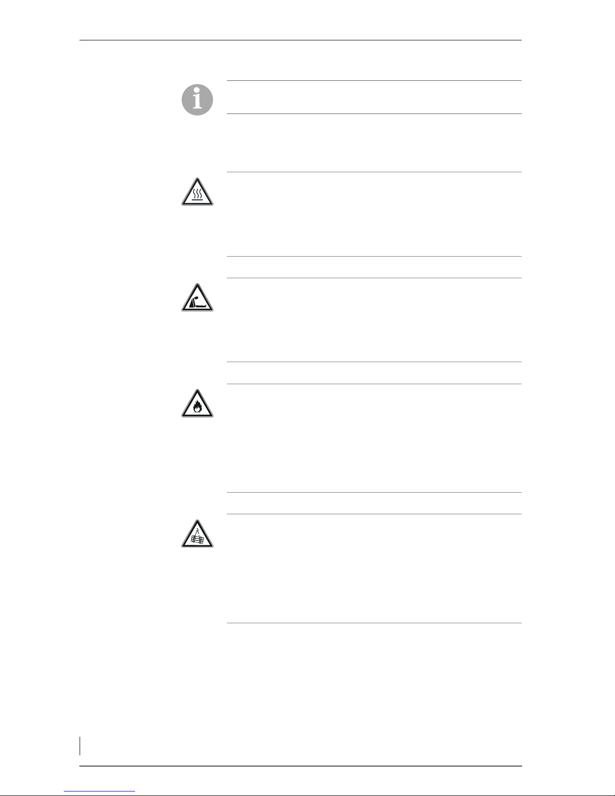
Caution!
Hot surfaces
Contact with the hot surfaces of the boiler can lead to burns.
Wait until the boiler has cooled down before touching non-insulated components.
Danger!
Danger of asphyxiation due to lack of oxygen
If the boiler is operating, carbon monoxide can be emitted through
the cleaning or inspection openings.
Do not leave these open any longer than necessary.
Warning!
Danger of fire
Opening doors and lids to hot combustion residues can pose the
danger of fires.
Keep the openings closed during operation, and when performing
cleaning work, allow the combustion residues to cool down before
you place them in a fireproof container.
Warning!
Danger from suspended loads
The boiler weighs over 1000 kg. If the boiler is dropped during
transport, persons can be seriously injured and the boiler can be damaged.
Make sure that you use appropriate lifting gear when placing the
boiler.
Page 13
© HDG Bavaria GmbH 07/2008 HDG Compact 99 - 200 - Version 1 - en
2 Safety instructions – Residual risks
13
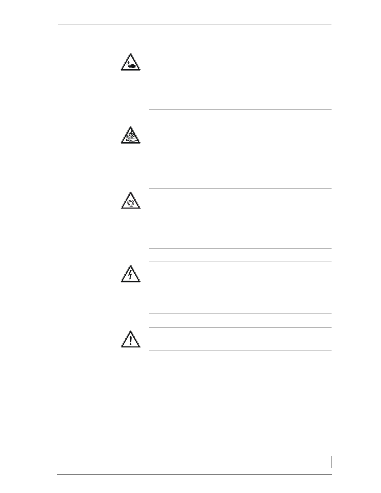
Warning!
Danger of injury
The cleaning shaft lid is very heavy and can fall shut. Hands and
arms could thereby be crushed.
Take care not to bump into the opened cleaning shaft lid and cause
it to fall shut.
Danger!
Danger of explosion due to carbon monoxide
When the boiler is in operation, carbon monoxide escaping from
open cleaning or inspection hatches can cause explosions.
Do not leave these open any longer than necessary.
Warning!
Risk of injury from automatically driven components
When working on the automatic ash removal or automatic cleaning
systems, hands and arms could be injured.
Turn off the main switch when performing any work on automatically driven components.
Danger!
Dangerous electrical current or voltage
The circuit boards and electrical components carry current.
Have work on electrical components performed only by a qualified
electrician and turn the main switch off.
Warning!
The boiler is under pressure.
Page 14
2 Safety instructions – Warnings and safety symbols used
14
HDG Compact 99 - 200 - Version 1 - en © HDG Bavaria GmbH 07/2008
2.3 Warnings and safety symbols used
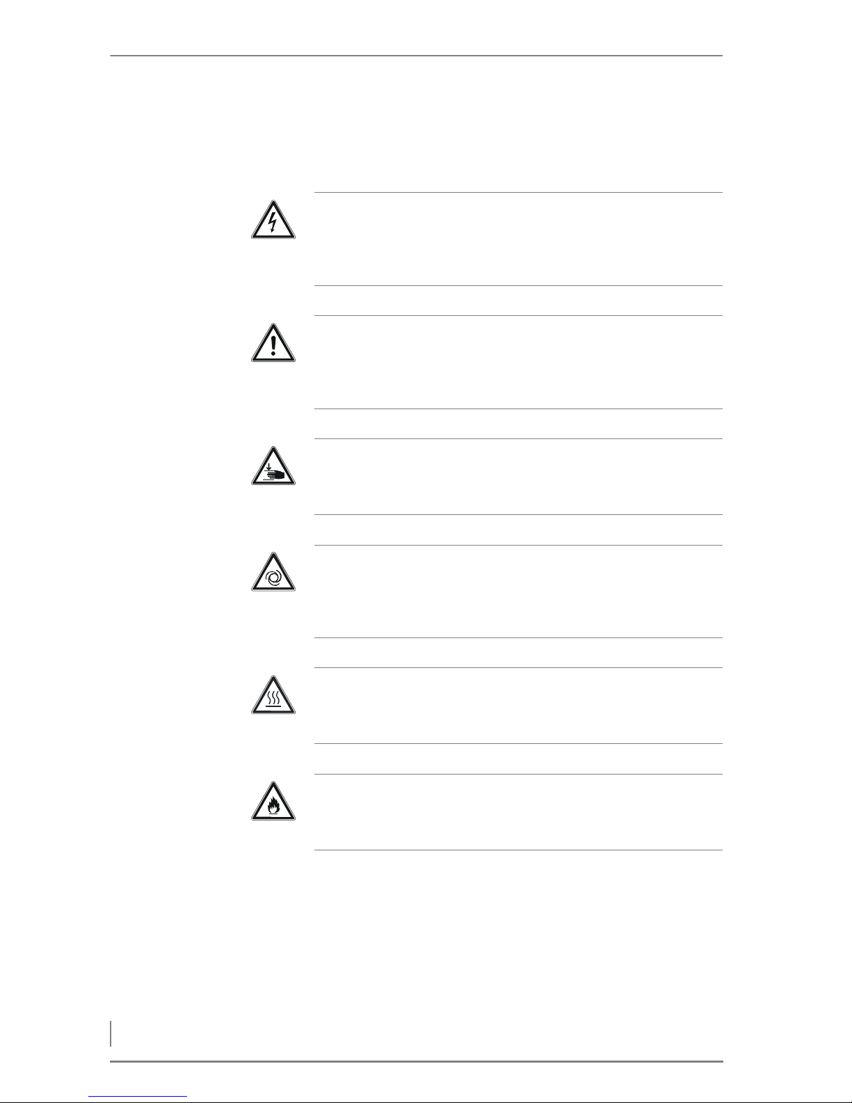
The following warnings and safety symbols are used in this Operating manual:
Danger!
Dangerous electrical current or voltage
Work in areas marked with this symbol may only be performed by a
qualified electrician.
Warning!
Hazardous area
Working in areas marked with this symbol can lead to serious injuries or to extensive material damage.
Warning!
Hand injuries can occur
Working in areas marked with this symbol can lead to hand injuries.
Warning!
Automatic start-up
Working in areas marked with this symbol can lead to injuries due
to automatic start-up.
Caution!
Hot surfaces
Working in areas marked with this symbol can lead to burns.
Warning!
Danger of fire
Working in areas marked with this symbol can lead to a fire.
Page 15
© HDG Bavaria GmbH 07/2008 HDG Compact 99 - 200 - Version 1 - en
2 Safety instructions – Duty of information
15
2.4 Duty of information
READING THE OPERATING
MANUAL
Every person performing any tasks on the system is required to read
the Operating manual prior to beginning work, particularly the
chapter “2 Safety instructions”.
This is especially important for persons who only occasionally work
on the heating system, for example when cleaning or servicing it.
The Operating manual must always be kept readily accessible at the
place where heating system is installed.
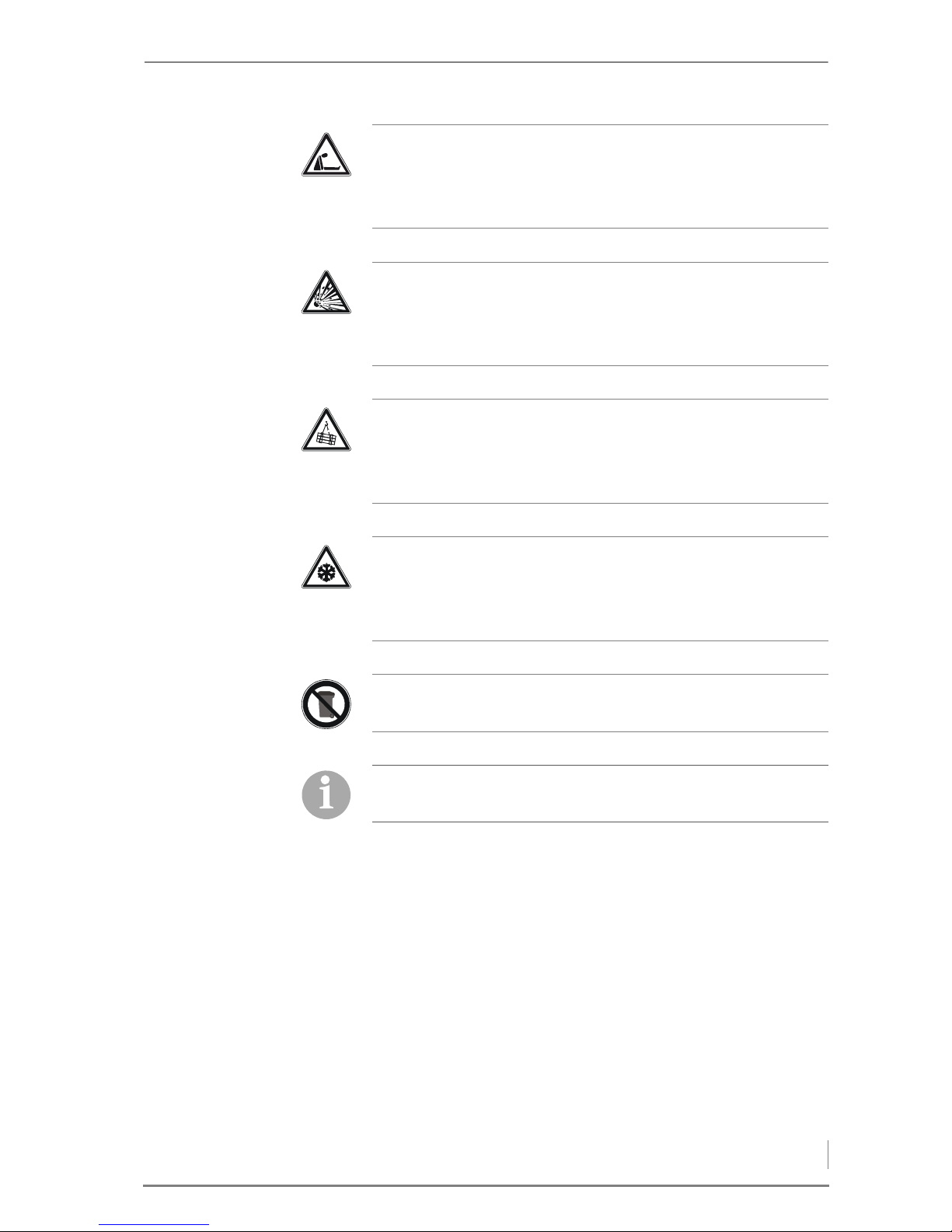
Danger!
Danger of asphyxiation due to lack of oxygen
When working in areas marked with this symbol, there is a danger
of asphyxiation due to high concentrations of carbon monoxide.
Danger!
Danger of explosion
When working in areas marked with this symbol, there is a danger
of explosion due to high concentrations of carbon monoxide.
Warning!
Suspended loads
When working in areas marked with this symbol, there is a danger
of falling objects.
Caution!
Frost danger
Work on locations marked with this symbol can lead to frost damage.
Instructions regarding disposal
Additional information for the operator
Page 16

3 Mode of operation – Overview
16
HDG Compact 99 - 200 - Version 1 - en © HDG Bavaria GmbH 07/2008
3 Mode of operation
3.1 Overview
The heating system HDG Compact 99 - 200 is equipped as standard
with the following:
• Automatic ash removal to the exterior ash container.
• Automatic cleaning of the heat exchanger surfaces.
The version of the heating system installed depends on whether the
feed system is to be fitted
• on the right side or
• on the left
side.
When selecting the feeding unit for the HDG Compact 99 - 200 heating system, you can choose between the following:
• TBZ 150 for feeding wood chips, planing shavings and pellets.
• Pellet vacuum delivery system with TBZ 80 for feeding the pellets.
The HDG Compact 99 - 200 heating system can also be equipped
with the following delivery systems:
• Flexi-blade delivery system FRA
• Jointed arm delivery system
• Walking floor delivery system
• Silo delivery system
• Pellet delivery system
Regarding the volume of the ash box, there are three different options:
• 80 l (standard)
• 140 l (optional)
• 240 l (central ash removal)
Unless otherwise specified, the product version with the TBZ 150
feed system on the left-hand side and the ash box with 80 l volume
will be illustrated and described in this Operating manual.
Page 17
© HDG Bavaria GmbH 07/2008 HDG Compact 99 - 200 - Version 1 - en
3 Mode of operation – Overview
17
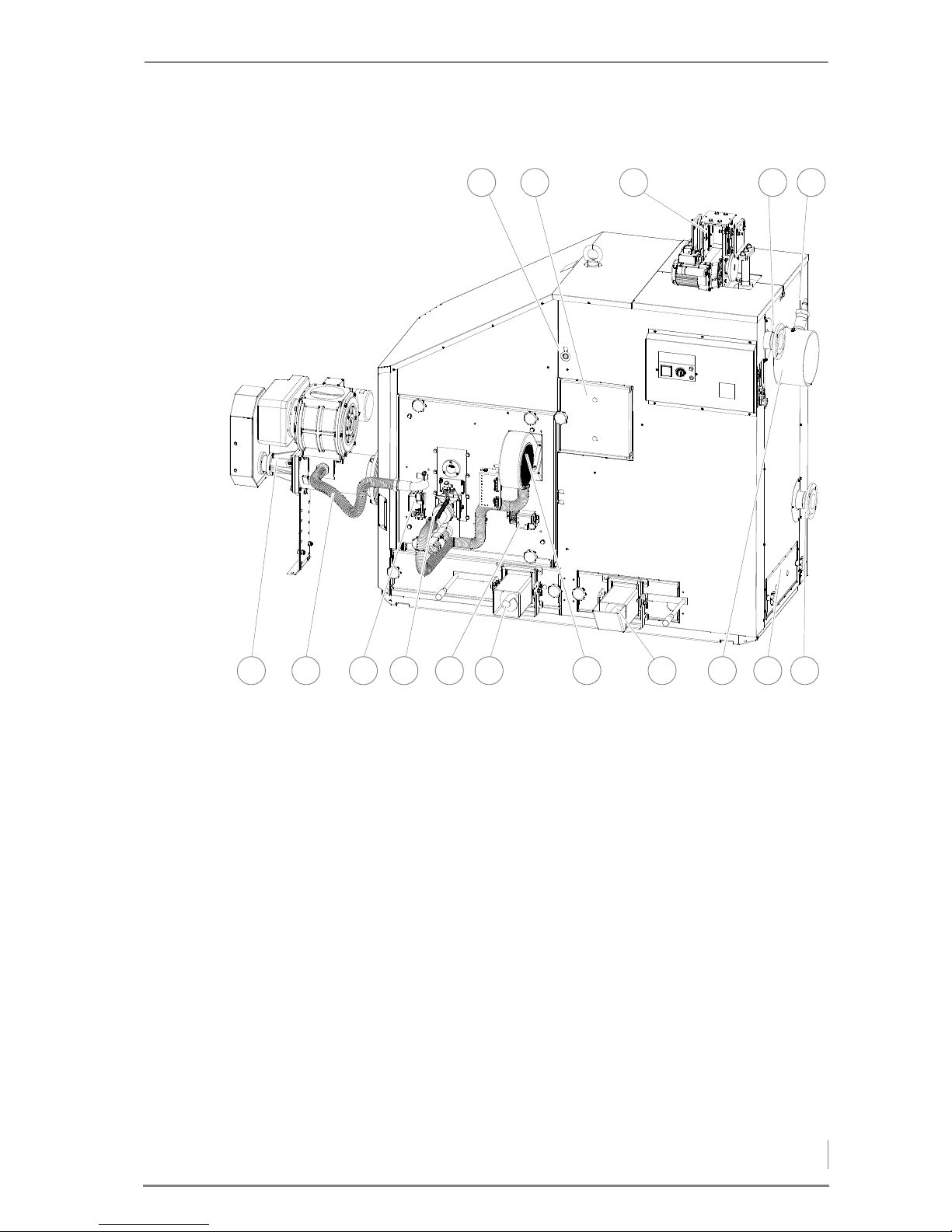
FRONT SIDE OF HDG COMPACT 99/100/105/115
1 Combustion chamber temperature sensor
2 Fly ash chamber inspection door
3 Cleaning system drive
4 Boiler supply connection (DN 65)
5 Lambda sensor
6 Boiler return connection (DN 65)
7 Fly ash chamber cleaning door
8 Flue pipe connection
9 Fly ash removal auger
10 Combustion fan
11 Combustion chamber ash removal auger
12 Servo motor for secondary air
13 Ignition fan
14 Servo motor for primary air
15 Pressure equalisation hose
16 Feeding system
Figure 3/1 - Front side of HDG Compact 99/100/105/115
9 8 7 6
4321
1013 12 1116 15 14
5
Page 18
3 Mode of operation – Overview
18
HDG Compact 99 - 200 - Version 1 - en © HDG Bavaria GmbH 07/2008
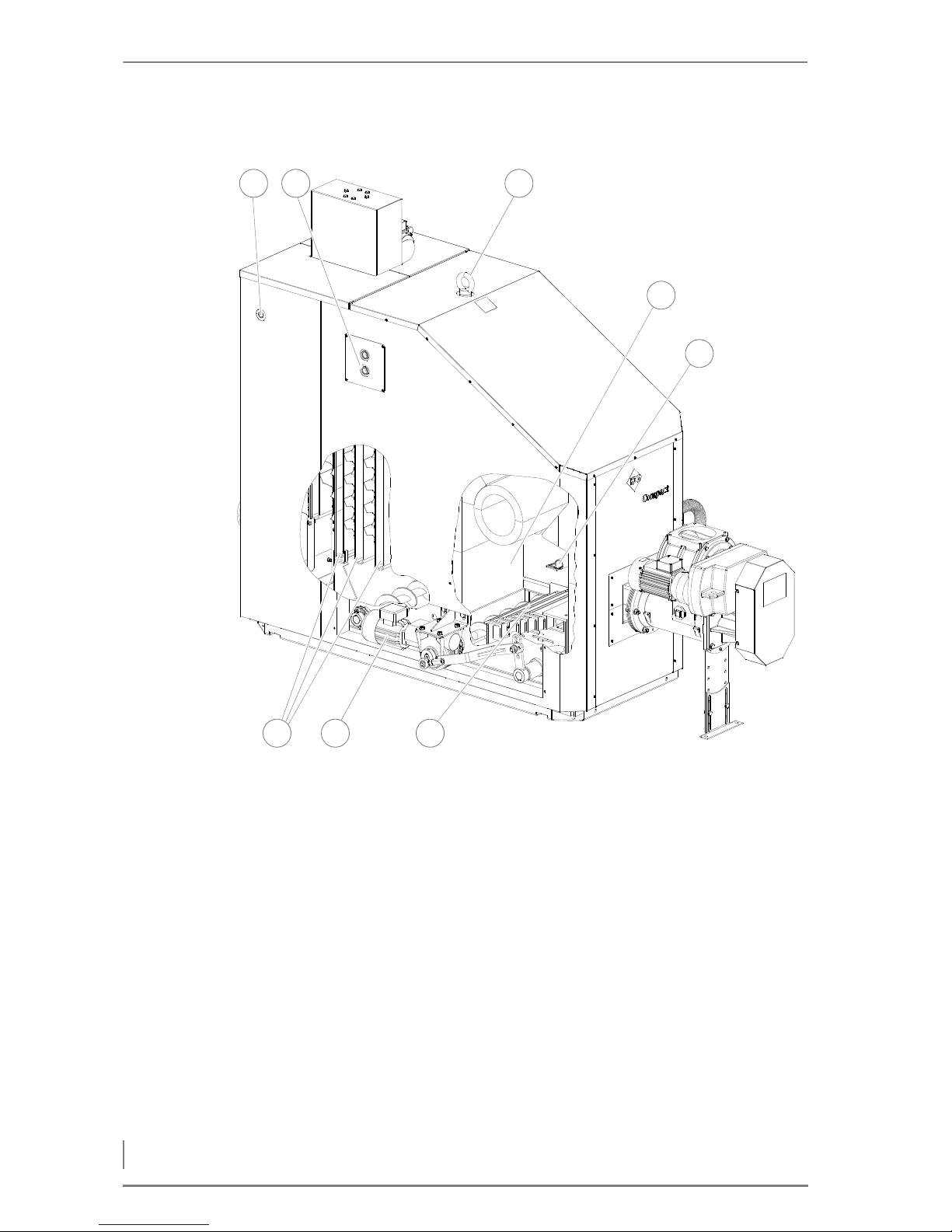
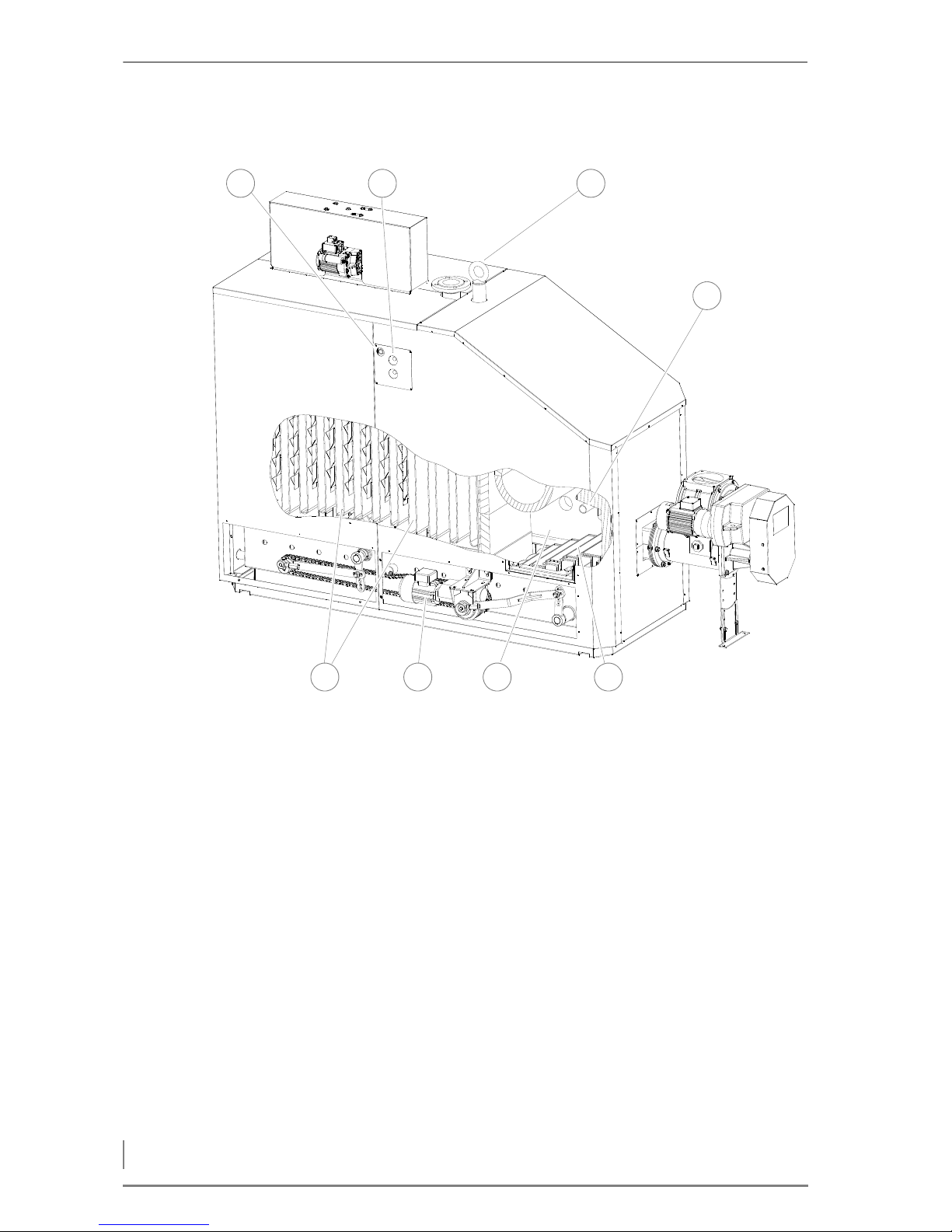
BACK SIDE OF HDG COMPACT 99/100/105/115
1 Connection of immersion sleeve for thermal safety device (DN 15,
inside thread)
2 Safety heat exchanger connections (DN 20, outside thread)
3 Eyebolt for crane transport
4 Combustion chamber
5 Fill level indicator
6 Stepped grate
7 Ash removal motor
8 Heat exchanger surfaces with cleaning turbulators in between
Figure 3/2 - Back side of HDG Compact 99/100/105/115
8 7 6
4
5
321
Page 19
© HDG Bavaria GmbH 07/2008 HDG Compact 99 - 200 - Version 1 - en
3 Mode of operation – Overview
19
FRONT SIDE OF HDG COMPACT 150/194/199/200
1 Combustion chamber temperature sensor
2 Fly ash chamber inspection doors
3 Boiler supply connection (DN 80)
4 Cleaning system drive
5 Flue pipe connection
6 Lambda sensor
7 Boiler return connection (DN 80)
8 Fly ash removal auger
9Combustion fan
10 Combustion chamber ash removal auger
11 Servo motor for secondary air
12 Ignition fan
13 Servo motor for primary air
14 Pressure equalisation hose
15 Feeding system
Figure 3/3 - Front side of HDG Compact 150/194/199/200
9 8
654321
713 12 11 101415
Page 20
3 Mode of operation – Overview
20
HDG Compact 99 - 200 - Version 1 - en © HDG Bavaria GmbH 07/2008
BACK SIDE OF HDG COMPACT 150/194/199/200
1 Connection of immersion sleeve for thermal safety device (DN 15,
inside thread)
2 Safety heat exchanger connections (DN 20, outside thread)
3 Eyebolt for crane transport
4 Fill level indicator
5 Stepped grate
6 Combustion chamber
7Ash removal motor
8 Heat exchanger surfaces with cleaning turbulators in between
Figure 3/4 - Back side of HDG Compact 150/194/199/200
4
4
8 7 6 5
321
Page 21
© HDG Bavaria GmbH 07/2008 HDG Compact 99 - 200 - Version 1 - en
3 Mode of operation – Functional description
21
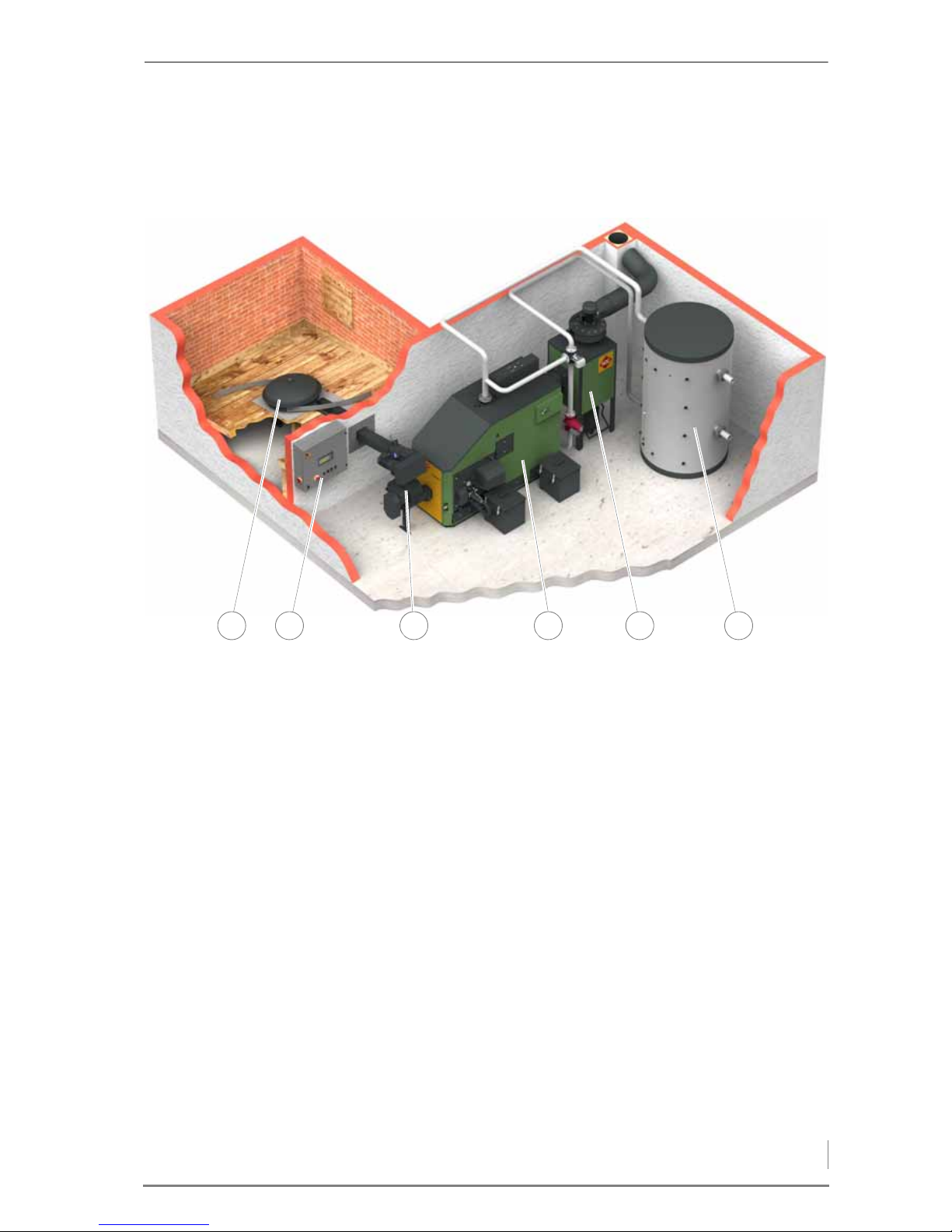
3.2 Functional description
The HDG Compact 99 - 200 heating system may contain the following components:
1 Delivery system
2 Control cabinet
3 Feeding system
4 HDG Compact 99 - 200 boiler
5 HDG cyclone dust extractor
6 Accumulator
COMBUSTION PROCESS
With the HDG Compact 99 - 200 heating system, the fuel is automatically fed from the bunker into the combustion chamber of the boiler
via the delivery and feeding systems. The combustion fan is already
activated here in order to eliminate any possible residual combustion
gases or negative flue pressure conditions along the combustion
path.
Once the filling cycle is complete, the fuel introduced into the combustion chamber is automatically ignited with an electrical ignition
fan. During the subsequent heating-up phase, the specified fuel feed
quantity is set.
Figure 3/5 - Overview
65321 4
Page 22

3 Mode of operation – Functional description
22
HDG Compact 99 - 200 - Version 1 - en © HDG Bavaria GmbH 07/2008
Following the heating-up phase, the system switches to automatic
operation. In this mode, combustion is carried out according to the
entered control options.
In order to free the grate from ash which collects during combustion,
every second grate segment of the grating moves back and forth periodically. The automatic cleaning system cleans the heat exchanger
surfaces using the turbulators which move up and down.
The combustion chamber ash and air space ash are propelled into
the individual external ash containers by the automatic ash removal
system using delivery augers.
The air necessary for combustion is supplied as required via two
servo motors.
Via sensors:
– Continuously monitor the firing;
– Adapt boiler output for the heat requirements
– Minimise emissions; and
– Optimise boiler efficiency.
DELIVERY SYSTEM
The delivery system is in the fuel bunker.
The fuel is transported from the fuel bunker to the dosing unit or to
the intermediate container.
The delivery system is controlled through the HDG Control.
HDG CONTROL
The boiler control HDG Control unit in the control cabinet is the electronic hub. This is a freely programmable PLC control.
Via the control unit, you can adjust the heating system HDG Compact
99 - 200 and obtain information on the current process status.
The current operating temperature is displayed.
Figure 3/6 - HDG Control control unit
$POmH
.POJUPS
J
Page 23

© HDG Bavaria GmbH 07/2008 HDG Compact 99 - 200 - Version 1 - en
3 Mode of operation – Functional description
23
CONTROL MODES
You can choose between four control modes:
• Fixed value:
– Constant feed rate and constant combustion air flow-rate
(even in emergency operation)
• Combustion control:
– Constant, specified combustion chamber temperature and op-
timal combustion through modification of primary and secondary air and fuel quantity
– No output regulation
– Preferred method of operation with buffer tank
• Control of combustion and power:
– Output supplied is adjusted to heat used with optimised com-
bustion
– Operation without accumulator
• Oil burner
– An oil burner is also fitted to the boiler.
• Log wood:
– Only suitable for emergency operation
Page 24
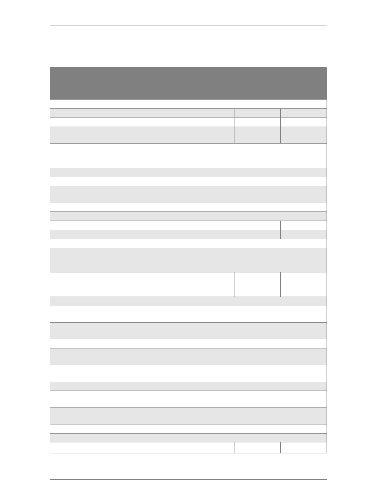
3 Mode of operation – Technical data
24
HDG Compact 99 - 200 - Version 1 - en © HDG Bavaria GmbH 07/2008
3.3 Technical data
*in combination with the HDG cyclone dust separator with flue gas fan
Boiler type
HDG Compact
99
Wood chips /
pellets
HDG Compact
100
Wood chips /
pellets
HDG Compact
105
Wood chips /
pellets
HDG Compact
115
Wood chips /
pellets
Performance data (measured according to DIN EN 303-5)
Nominal thermal power 99.0 kW 100.0 kW 105.0 kW 115.0 kW
Minimum thermal output 30.0 kW 30.0 kW 31.5 kW 34.5 kW
Boiler efficiency at nominal
thermal power
90.4 / 91.5 % 90.4 / 91.5 % 90.4 / 91.4 % 90.4 / 91.3 %
Electrical connection: Voltage
Frequency
Back-up fuse
230 / 400 V
50 Hz
20 A
General boiler data
Boiler class 3
Maximum permissible opera-
ting pressure
3.0 bar
Maximum supply temperature 95 °C
Minimum return temperature 60 °C
Water capacity 210 l 225 l
Weight (net) 1540 kg 1585 kg
Planning data for flue calculation (DIN EN 13384-1)
Flue gas temperature (Tw) at
• Nominal thermal power
• Minimum thermal power
200 °C
140 °C
Flue gas mass flow at
• Nominal thermal power
• Minimum thermal power
0.0610/0.0650kg/s
0.0210/0.0200kg/s
0.0610/0.0650kg/s
0.0210/0.0200kg/s
0.0642/0.0673kg/s
0.0223/0.0209kg/s
0.0681/0.0682kg/s
0.0246/0.0223kg/s
Flue draught requirement (Pw) 20/10* Pa
Diameter of flue gas pipe con-
nection 250 mm
Height at middle of flue pipe
connection
1250 mm
Water-side connections
Supply and return connections
(flange)
DN 65
Connection for safety heat
exchanger (bushing) DN 20, inside thread
Connection for drain (bushing) DN 15, inside thread
Recommended pipe dimensi-
ons (minimum) DN 65
Water-side resistance at nomi-
nal thermal power,10 K
6500 Pa
Other
Sound pressure level emitted < 70 dB(A)
Minimum Air inlet cross-section
250 cm
2
250 cm
2
260 cm
2
280 cm
2
Table 3/1 - Technical data
Page 25
© HDG Bavaria GmbH 07/2008 HDG Compact 99 - 200 - Version 1 - en
3 Mode of operation – Technical data
25
*in combination with the HDG cyclone dust separator with flue gas fan
Boiler type
HDG Compact
150
Wood chips /
pellets
HDG Compact
194
Pellets
HDG Compact
199
Wood chips
HDG Compact
200
Wood chips /
pellets
Performance data (measured according to DIN EN 303-5)
Nominal thermal power 150.0 kW 194.0 kW 199.0 kW 190.0 kW
Minimum thermal output 45.0 kW 47.0 kW 57.0 kW 57.0/47.0 kW,
Boiler efficiency at nominal
thermal power
90.4 / 90.7 % 90.1 % 90.4 % 90.4 / 90.1 %
Electrical connection: Voltage
Frequency
Back-up fuse
230 / 400 V
50 Hz
20 A
General boiler data
Boiler class 3
Maximum permissible opera-
ting pressure
3.0 bar
Maximum supply temperature 95 °C
Minimum return temperature 60 °C
Water capacity 450 l
Weight (net) 2140 kg 2220 kg 2220 kg 2220 kg
Planning data for flue calculation (DIN EN 13384-1)
Flue gas temperature (Tw) at
• Nominal thermal power
• Minimum thermal power
200 °C
130°C
200 °C
140 °C
200 °C
150 °C
230°C
150°C
Flue gas mass flow at
• Nominal thermal power
• Minimum thermal power
0.0927/0.0878kg/s
0.0338/0.0294kg/s
0.1060kg/s
0.0370kg/s
0.1290kg/s
0.0460kg/s
0.1180/0.1060kg/s
0.0440/0.0370kg/s
Flue draught requirement (Pw) 20/13* 20/18* Pa 20/15* 20/15*
Diameter of flue gas pipe con-
nection 300 mm
Height at middle of flue pipe
connection
1250 mm
Water-side connections
Supply and return connections
(flange)
DN 80
Connection for safety heat
exchanger (bushing) DN 20, inside thread
Connection for drain (bushing) DN 25, inside thread
Recommended pipe dimensi-
ons (minimum) DN 80
Water-side resistance at nomi-
nal thermal power,10 K
6000 Pa
Other
Sound pressure level emitted < 70 dB(A)
Minimum Air inlet cross-section 350 cm 438 cm 468 cm 430 cm
Table 3/2 - Technical data
Page 26

3 Mode of operation – Fuel quality requirements
26
HDG Compact 99 - 200 - Version 1 - en © HDG Bavaria GmbH 07/2008
3.4 Fuel quality requirements
PERMISSIBLE FUEL
The HDG Compact 99 - 200 heating system is designed for the standard use of burning wood fuel products made from untreated wood
in the form of wood chips, shavings and wood pellets.
According to §3 (1) 1. In accordance with German law BimSchV, the
fuel classes 4, 5a, 6, and 7 may be used in this heating system.
F
UEL CLASS 4 Untreated log wood including adhering bark, such as wood chips.
F
UEL CLASS 5 Untreated wood (not log wood), such as shavings.
F
UEL CLASS 5A Pellets made of untreated wood in the form of wood pellets or wood
briquettes
F
UEL CLASS 6 Painted, varnished or coated wood including remains thereof, pro-
vided no wood protection agents have been applied or are present
as the result of a treatment, and coatings do not contain organic halogen compounds or containing heavy metals.
F
UEL CLASS 7 Plywood, chipboard, fibreboard or otherwise glued wood including
remains thereof, provided no wood protection agents have been applied or are present as the result of a treatment, and coatings do not
contain organic halogen compounds or heavy metals.
Fuel classes 6 or 7 may only be used in a wood processing plant at 30
kW or more nominal thermal power. In the case of painted, varnished
or coated wood, it should be noted that greater stress can be placed
on the wearing parts such as wall lining, fill level and lambda sensors,
which may reduce their service lives.
C
OMPOSITION OF THE FUEL Knowledge of the fuel composition forms the basis for the combus-
tion calculation and the treatment of operating issues relating to firing technology. In addition to combustible substances, the fuels
also contain varying amounts of non-combustible components, so
called inert components
With an increasing ratio of inert components, the thermal temperature drops and the amount of ash and cinder dirt on the heating surfaces is increased.
Page 27

© HDG Bavaria GmbH 07/2008 HDG Compact 99 - 200 - Version 1 - en
3 Mode of operation – Fuel quality requirements
27
WOOD CHIPS
Regarding the origin of the wood, a distinction is made between category A1 and A2. For A1 the wood comes from trunk wood and chemically untreated wood residue; for category A2 the wood of the
entire tree and forestry waste can be used. Wood from both category
A1 and A2 can be used in HDG boilers.
Essential criteria are the particle size, moisture content and ash content of the fuel.
P
ARTICLE SIZE In accordance with DIN EN 14961-4, the fuel specifications for wood
chips are separated into
• P31.5
Wood chips with a typical particle size smaller than 31.5 (P31.5) are a
machine-compatible material suitable primarily for small systems.
Oversized pieces (end pieces) could lead to malfunctions during
system operation. Higher proportions of finer content (dust) can lead
to high emissions and ejection of glowing particles.
Wood chips from category P31.5 can be used as fuel in all HDG wood
chip boilers. For P31.5 wood chips, at least 75% of the wood chips (by
weight) must be between 8 mm and 31.5 mm. The fine content
(<31.5 mm) may not exceed a max. of 8 % by weight. A max. of 6% by
weight of the wood chips may be longer than 45 mm; lengths greater than 120 mm are not allowed. The numeric value of the P class
refers to the size of the wood chips in mm, which fit through a round
opening with the indicated sieve opening size. The cross-section of
the outsized particles must be smaller than 2 cm
2
.
• P45
Medium wood chips with a particle size of up to 45 mm (P45) are
used in larger systems, but can however, depending on the diameter
of the conveyor auger, also still be suitable for small systems.
Wood chips from category 45 can be used as fuel in all HDG HDG
Compact 99 - 200 wood chip boilers. For P45 wood chips at least 75%
by weight of the wood chips must measure between 8 mm and 45
mm. The fine content (<31.5 mm) may not exceed a max. of 8 % by
weight. A max. of 6% by weight of the wood chips may be more than
63 mm and 3.5% by weight may be over 100 mm. Lengths greater
than 120 mm are not permissible. The numeric value of the P category refers to the size of the wood chips in mm, which fit through a
round opening with the indicated sieve size. The cross-section of the
outsized particles must be smaller than 5 cm
2
.
W
ATER CONTENT When selecting fuel, note that the heating value of the wood is pri-
marily dependent on the water content. The more water contained
in the wood, the smaller the thermal value since the water vaporises
in the course of the burning process and thereby consumes heat.
With regard to the quality standards for wood chips, DIN EN 149614 "Solid biofuels - fuel specifications and classes - wood chips for
non-industrial use" applies
Page 28
3 Mode of operation – Fuel quality requirements
28
HDG Compact 99 - 200 - Version 1 - en © HDG Bavaria GmbH 07/2008
This results in lower efficiency and thereby leads to greater wood
consumption. Increasing moisture in the fuel material also causes reduced efficiency, greater amounts of ash and smoke, as well as making it increasingly unfit for storage.
The maximum permissible water content of the wood chips for the
HDG Compact 99 - 200 is 30 % (M30).
For technical considerations, a representative thermal value is selected depending on water content. For burning that is both economical and low on emissions, the thermal value should not be less
than 3 kWh/kg.
A
SH CONTENT The ash content for wood in category 2 is higher than that of cate-
gory A1 due to the higher proportion of bark, needles and leaves.
The maximum permissible ash content of wood chips for the HDG
Compact 99 - 200 is 1.5 % by weight (A1.5).
WOOD PELLETS
Wood pellets are pressed into a cylindrical shape. They consist of untreated shavings and sawdust from the wood processing industry as
well as unprocessed forestry waste. They have a standardised diameter and length. They are pressed at a very high pressure and have
a very low water content. The energy contained in 2 kg of pellets corresponds approximately to the energy contained in a litre of heating
oil.
In accordance with DIN EN 14961-2, the fuel specifications for wood
pellets are separated into categories A1 and A2. The diameter of the
employed pellets must be in accordance with D06.
• A1/D06
The diameter of the pellets must be 6 mm +/- 1 mm. The length of
the pellets must measure between 31.5 mm and 40 mm. A maximum
of 1% by weight of the pellets may be longer than 45 mm. The water
content must be less than 10% (M10), the ash content must be less
than 0.7% by weight (A0.7).
Water content Moisture Thermal value
Relative wood
consumption
Combustion tem-
perature
10.0 % 11.1 % 3.9 kWh/kg 113 % 1150 °C
20.0 % 25.0 % 3.4 kWh/kg 130 % 1100 °C
26.0 % 35.0 % 3.1 kWh/kg 151 % 1070 °C
30.0 % 42.9 % 2.9 kWh/kg 171 % 1040 °C
Table 3/3 - Thermal value depending on water content
With regard to the quality standards for wood pellets, DIN EN
14961-2 "Solid biofuels - fuel specifications and classes - wood pellets for non-industrial use" applies.
Page 29
© HDG Bavaria GmbH 07/2008 HDG Compact 99 - 200 - Version 1 - en
3 Mode of operation – Fuel quality requirements
29
• A2/D06
The diameter of the pellets must be 6 mm +/- 1 mm. The length of
the pellets must measure between 31.5 mm and 40 mm. A maximum
of 1% by weight of the pellets may be longer than 45 mm. The water
content must be less than 10% (M10), the ash content must be less
than 1.5% by weight (A1.5).
RECOMMENDED FUEL
Suitable as fuel for the heating system HDG Compact 99 - 200 are
wood chips, shavings and wood pellets. In order to uphold the emission values specified in BImSchV, all fuel requirements, e.g. size,
water content, ash content, must be fulfilled.
W
OOD CHIPS HDG Bavaria recommends wood chips with particle size P31.5. The
fuel should have as little water content as possible, with a 20% water
content (M20) being ideal. The drier the fuel, the higher the thermal
value and the better the burning that is achieved. High quality fuel
aids in energy conservation and maintains the operating safety of
your heating system. The optimal ash content is 1% by weight (A1.0).
For HDG Compact 99 - 200 heating systems, it is possible to use wood
fuel products of grain size P45 with a maximum water content of up
to 30 %. However, reduced nominal thermal power, reduced efficiency, increased fuel consumption and greater wear and tear on the
Standard A1 wood pellets A2 wood pellets
Length 3.15 - 40 mm 3.15 - 40 mm
Diameter Ø D06: 6 mm +/-1 mm D06: 6 mm +/-1 mm
Thermal value 16.5 - 19 mJ/kg or
4.6 - 5.3 kWh/kg
16.3 - 19 mJ/kg or
4.5 - 5.3 kWh/kg
Density (spec. gravity)
1.0 – 1.4 kg/dm
3
min. 1.12 kg/dm
3
Bulk weight
min. 600 kg/m
3
min. 600 kg/m
3
Water content max. 10 % max. 10%
Ash content max. 0.7 % max. 1.5%
Fine material max. 1.0 % max. 1.0 %
Sulphur content max. 0.03 % max. 0.03%
Nitrogen content max. 0.3 % max. 0.5%
Chlorine content max. 0.02 % max. 0.02%
Additive max. 2.0 % max. 2.0 %
Table 3/4 - Burning characteristics of wood pellets
Page 30
3 Mode of operation – Fuel quality requirements
30
HDG Compact 99 - 200 - Version 1 - en © HDG Bavaria GmbH 07/2008
heating system may then result. Fuels with a higher water content
are not suitable for burning. The maximum permissible ash content is
1.5 .% by weight. (A1.5).
W
OOD PELLETS For operation of the heating system with wood pellets, HDG Bavaria
recommends wood pellets from category A1 according to DIN EN
14961-2 or, alternatively, with the certificate "ENplus" or "DINplus".
N
OMINAL THERMAL VALUE
DEPENDING ON WATER
CONTENT
The following table indicates the maximum nominal thermal value
depending on water content, in reference to the fuels approved for
the HDG Compact 99 - 200 in accordance with DIN EN 14961 "Solid
biofuels - fuel specifications and classes".
Pay particular attention to the fuel quality, both when ordering and
during the delivery.
Important!
If there is a significant change of fuel, the system must be reset accordingly and checked for emissions by authorised specialists.
Wood chips
P45, M20, A1.0
(A1.5) or
Pellets A1, A2
Wood chips
P45, M25, A1.0
(A1.5)
Wood chips
P45, M30, A1.0
(A1.5)
Shaving
briquettes A1,
A2, D60, L50
Planing/saw
shavings A1,
A2, M20, A1.0
(A1.5)
HDG Compact
99
99 kW 89 kW, (86 kW) 84 kW, (79 kW) 92 kW 84 kW, (79 kW)
HDG Compact
100
100 kW 90 kW, (87 kW) 85 kW, (80 kW) 93 kW 85 kW, (80 kW)
HDG Compact
105
105 kW 93 kW, (90 kW) 87 kW, (82 kW) 95 kW 87 kW, (82 kW)
HDG Compact
115
115 kW 103 kW,
(100 kW)
97 kW, (92 kW) 105 kW 97 kW, (92 kW)
HDG Compact
150
150 kW 145 kW
(140 kW)
138 kW
(135 kW)
145 kW 138 kW
(135 kW)
HDG Compact
194
194 kW - - - -
HDG Compact
199
199 kW 179 kW
(174 kW)
172 kW
(169kW)
184 kW 172 kW
(169 kW)
HDG Compact
200
190 kW 180 kW
(175 kW)
173 kW
(170 kW)
185 kW 173 kW
(170 kW)
Table 3/5 - Max. nominal thermal value depending on water content
Page 31
4 Planning and installation – Planning the heating system
31
4 Planning and installation
4.1 Planning the heating system
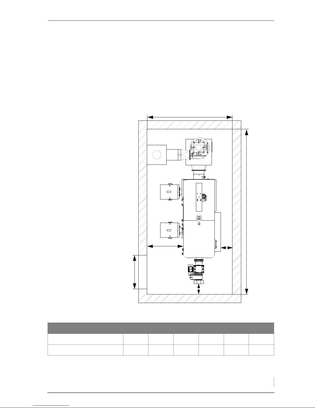
REQUIRED ROOM SIZES AND MINIMUM SPACING
• Minimum ceiling height: 2250 mm / optimal ceiling height:
2500-2750 mm
Figure 4/1 - Necessary room sizes and minimum spacing
E
F
D
B
C
A
A B C D E F
HDG Compact 99/100/105/115 2280 3500 813 280 330 1000
HDG Compact 150/194/199/200 2400 4650 935 280 330 1000
Table 4/1 - Minimum size (mm)
Page 32

4 Planning and installation – Planning the heating system
32
DIMENSIONS
The following table contains the dimensions of the boiler.
*without ash container
BOILER ROOM
Furnaces for solid fuels with a nominal thermal power of more than
50 kW may only be installed in special boiler rooms.
A
PPLICABLE REGULATIONS Local building regulations always apply. In Germany, individual state
regulations on boilers and furnaces (FeuVO) also apply.
Make sure there is an adequate supply of fresh air to the boiler room
so that there is enough air available for the combustion process and
to protect the operator from the hazards of insufficient oxygen.
I
NSTALLATION A base is not necessary for installation of the heating system. Ensure
that it is aligned on a horizontal plane.
To ensure unhindered operation and maintenance of the heating
system, you must ensure that the heating system is installed to our
specifications and that the minimum spacings are maintained.
Also note that the thresholds in DIN 4109 “Soundproofing in building
construction” may not be exceeded.
More detailed information can be found in the respective ordinances
of the German states.
We recommend that objects which are not needed for the operation
or maintenance of the heating system, are not stored in the boiler
room.
HDG Compact 99/100/105/115 HDG Compact 150/194/199/200
Length 1130 mm* 1370 mm*
Width 1980 mm 2410 mm
Height 1890 mm 1940 mm
Table 4/2 - Dimensions
Building regulations may differ from country to country and state to
state.
For this reason, consult a qualified specialist for the planning and installation of your heating room.
Observe the fire safety regulations.
Also observe the accident prevention regulations of the official safety organisations.
Page 33

4 Planning and installation – Planning the heating system
33
FUEL BUNKER
The fuel bunker should have the following characteristics:
•dry
•dust-proof
• statically suitable
• accessible for the filling process
• free of other installations, especially in existing buildings
• adapted to fuel requirements
The refilling intervals should be kept as long as possible. The heating
system should be located so that the noise generated does not exceed DIN 4109, “Soundproofing in building construction”.
P
ROPER DIMENSIONING The size of the fuel bunker depends on the heating system, the deter-
mined thermal load, the resulting annual fuel requirements and existing building conditions. Practice has shown that filling the fuel
bunker four to six times per heating period is desirable.
P
ASSAGE THROUGH THE WALL The passage through the wall normally has to be made in the wall
between the heating room and the fuel bunker. Its position depends
on the distance and the position of the HDG Compact heating
system within the room and the customer's installation diagram. The
passage through the wall between the heating room and the fuel
bunker should have a width of 70 cm and height of 70 cm in order to
allow the assembly of the delivery auger.
V
ENTILATION OF FUEL BUNKERS Wood fuel products with higher moisture can cause relatively high
air humidity in the fuel bunker. Cold surfaces may thereby experience a drop below the dew point and develop condensation water.
This condensation water often occurs on non-insulated lids, doors or
cold walls and can result in a further moistening of the fuel.
It is therefore recommended to provide a suitable ventilation system
that corresponds to the building's features.
Page 34
4 Planning and installation – Planning the heating system
34
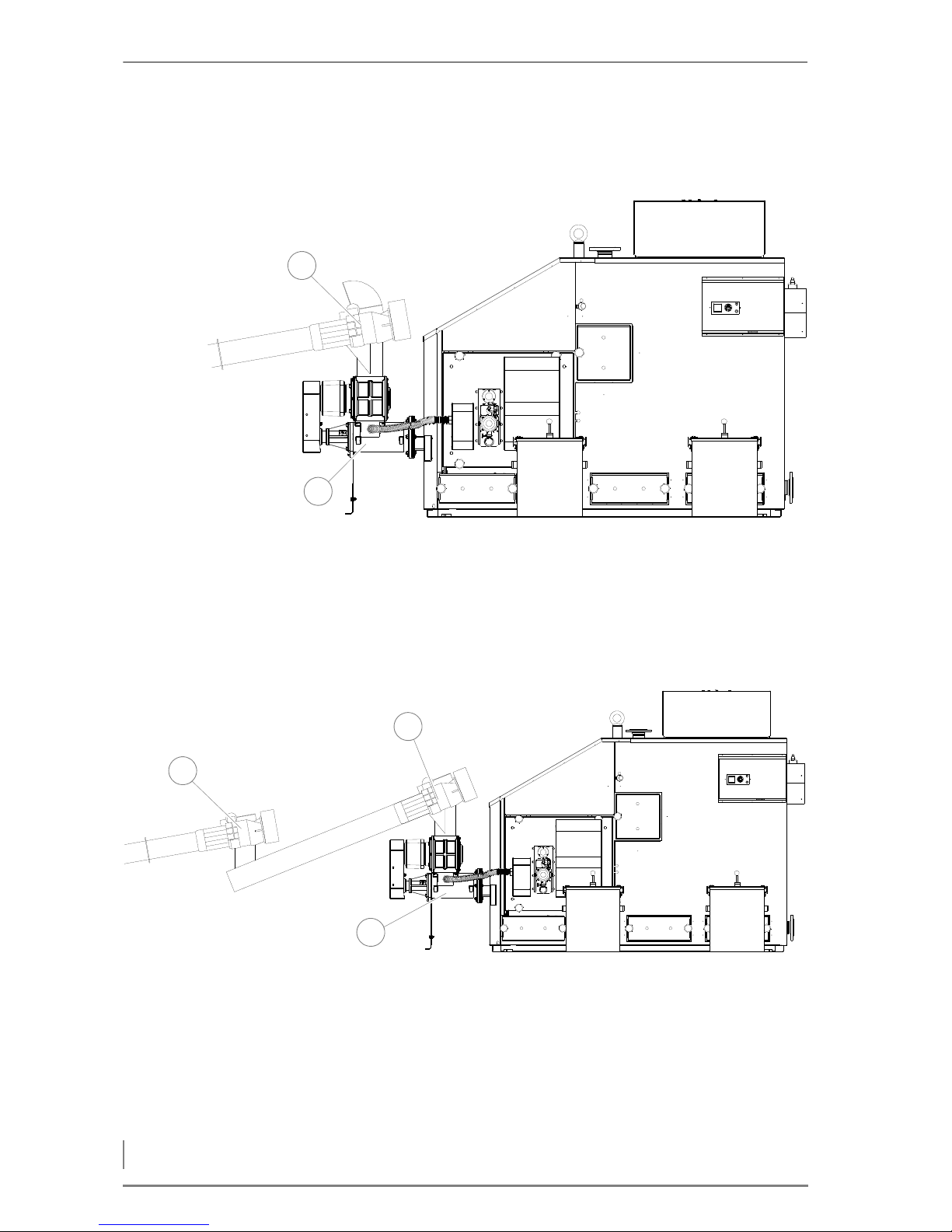
DELIVERY SYSTEM VERSIONS
Delivery version 1 - Dosage directly to TBZ
1Dosage
2Feeding system
Delivery version 2 - Dosage, conveyor auger to TBZ
1 Dosage system II (motor of delivery system runs along with do-
sage system)
2Dosage
3Feeding system
Figure 4/2 - Delivery system version 1
1
2
Figure 4/3 - Delivery system version 2
1
3
2
Page 35
4 Planning and installation – Planning the heating system
35
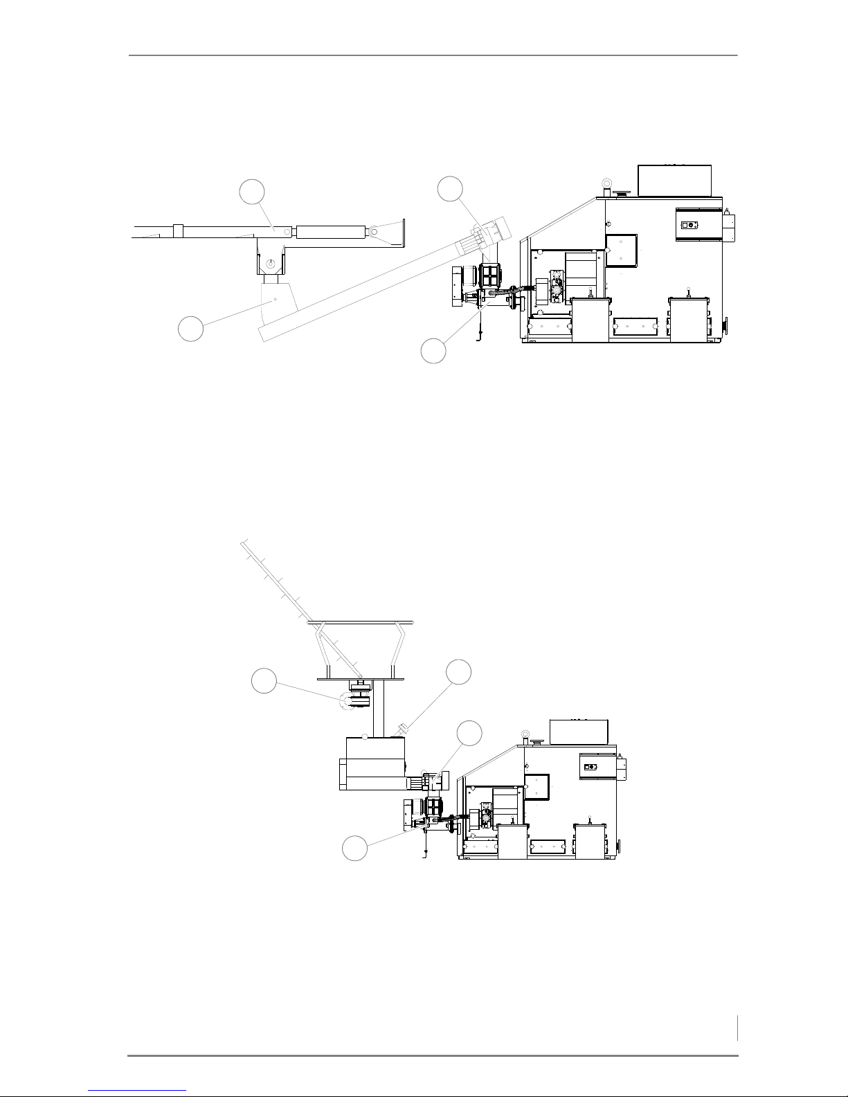
Delivery version 3 - External delivery
1 Delivery system
2Dosage
3 Feeding system
4 Fill level indicator
Delivery version 4 - sloping auger delivery, silo delivery system
1 Delivery system
2 Fill level indicator
3Dosage
4 Feeding system
Figure 4/4 - Delivery system version 3
1
4
3
2
Figure 4/5 - Delivery system version 4
4
3
2
1
Page 36
4 Planning and installation – Connections
36
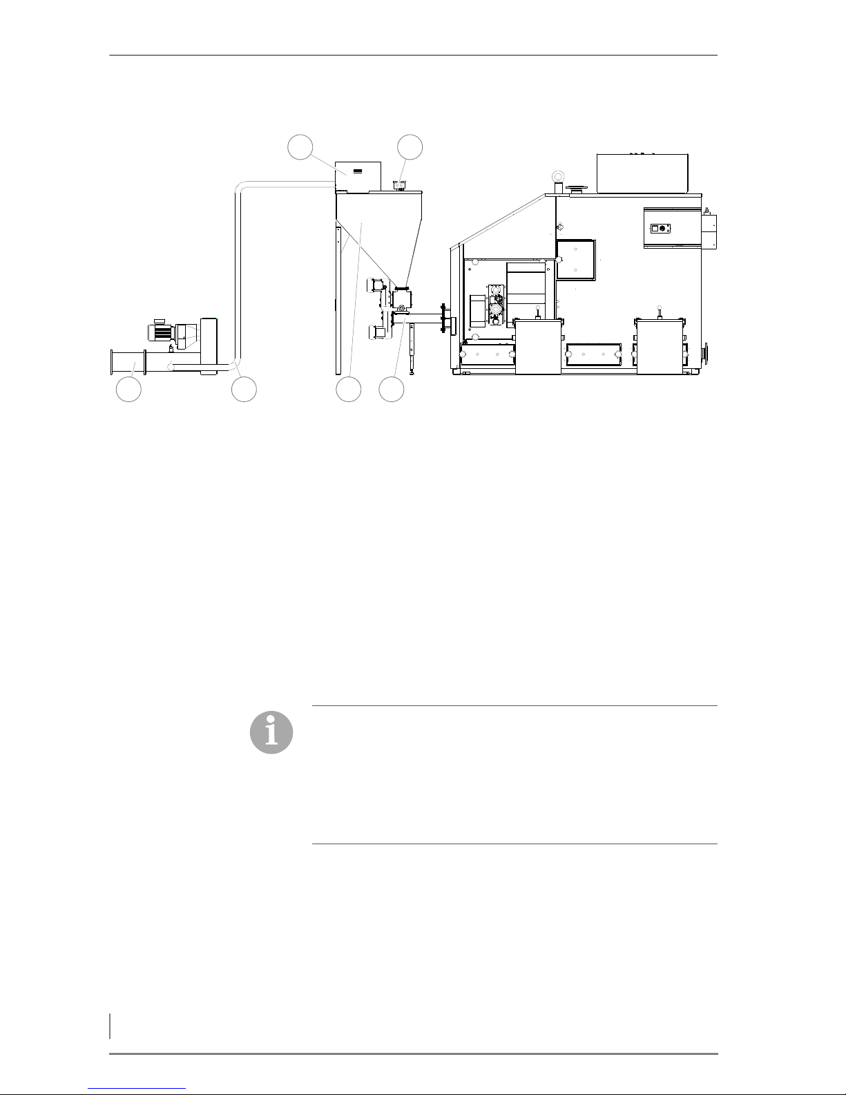
Delivery version 5 - pellet vacuum container
1 Vacuum + noise insulation hood
2 Fill level indicator
3Feeding system
4 Pellet vacuum container
5 Pellet suction line
6 Pellet delivery auger
4.2 Connections
CHIMNEY
The benefits of the HDG Compact 99 - 200 can only be reaped if all of
the factors necessary for good combustion are carefully adjusted.
The heating system and chimney form a single functional unit and
must be adapted to one another in order to guarantee fault-free and
economical operation.
Figure 4/6 - Delivery system version 5
6 5 4 3
21
According to EN 303-5, the entire flue system must be installed in
such a way that contamination, condensation and insufficient flue
draught are avoided. Here it is to be noted that, in the accessible
operational area of the boiler, flue gas temperatures of less than 160
K above room temperature may arise.
✎ The required flue gas values are listed in chapter “3 Mode of ope-
ration”, section “3.3 Technical data”.
Page 37

4 Planning and installation – Connections
37
Since the flue temperature may lie below 100 °C when the system is
partially loaded, a chimney/flue is required which meets the requirements of DIN EN 13384-1: 2003-03 “Thermal and fluid dynamic calculation methods”. If it does not meet this standard, contact your
specialist heating company or chimney technician.
Another essential criterion is to achieve the correct conveying pressure. This depends on three major factors.
C
HIMNEY CHARACTERISTICS The requirements for minimising the draught loss in the chimney are:
• Good thermal insulation to avoid the flue gases cooling down too
quickly.
• Smooth interior surface to reduce the flow resistance.
• Chimney well-sealed to avoid outside air leaking in. Air penetrating from the outside speeds up the cooling of the flue gases.
These requirements correspond to chimneys of the type according
to DIN EN 13384-1: 2003-03 “Thermal and fluid dynamic calculation
methods”.
Free-standing chimneys require particularly good insulation.
C
HIMNEY DIMENSIONS The system may only be connected to a chimney which has been di-
mensioned in accordance with DIN EN 13384-1, taking into account
the fuel planned and the expected load, and which meets local building regulations for the installation site.
A chimney can only be designed with full knowledge of the on-site
conditions. This includes taking into account the following factors:
• Location of the house
– Surrounding hills/slopes
– Wind direction
• Location of the chimney in the roof
– The opening of the chimney must be at least 0.5 m above the
highest edge of roofs with a slope of more than 20° or at least
1.0 m higher than roof surfaces which slope at 20° or less.
• The effective height of a chimney is measured from the entrance
into the flue to the end of the chimney.
C
ONNECTING THE BOILER TO
THE CHIMNEY
The boiler must be connected to the flue with a connecting piece
which is as short as possible, at an angle which is less than 30-45° to
the chimney. You should aim for a connecting piece with a maximum
length of 1 m using just one fitting.
Every additional fitting results in a greater pressure loss in the exhaust path and should thus be avoided. The same is true for overlong
connecting pieces. If, for constructional reasons, they have to be
When planning the flue system, a flue calculation based on DIN EN
13384-1 must be performed by authorised specialists.
Page 38
4 Planning and installation – Connections
38
longer than 1 m, they should be adequately insulated (at least 5 cm
of mineral wool or equivalent material) and, if possible, should be
fitted with an upward inclination.
To compensate for irregularities in the flue draught of the chimney,
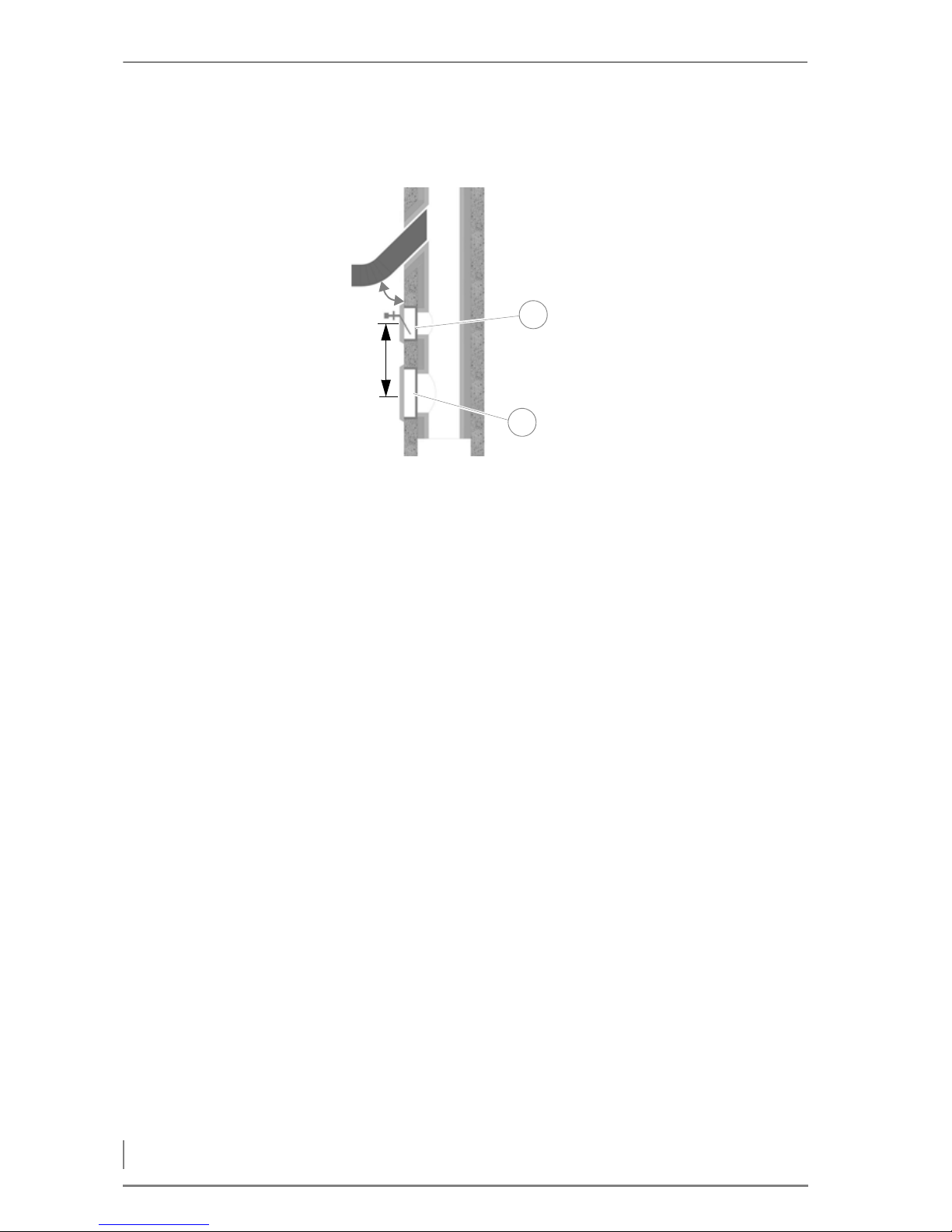
HDG Bavaria recommends installing an auxiliary air unit in the flue
pipe, or even better, in the chimney itself as shown in Figure 4/7 -
Connection to the chimney.
The following should also be considered:
• The connecting piece may not protrude into the chimney.
• If the system flue pipe has a larger diameter than the chimney, the
connecting piece must reduce to the diameter of the connection.
In this case, the connecting piece should taper as gently as possible.
• Use bends rather than elbows; the radius of the elbow may not be
less than the diameter of the pipe.
• The chimney should be vertical and straight, if possible without
kinks (take particular care in older buildings).
• All of the cleaning and measurement hatches on the chimney
must be tightly sealed.
• To reduce the entry of additional cold air, only attach one heat generator per chimney.
• To prevent dust from escaping, the flue pipe must be sealed with
heat-resistant silicone.
ELECTRICAL SYSTEM
The directives of 2006/95/EC (low voltage guidelines) must be followed for the electrical connections to the system.
No electrical installations, such as power sockets, distribution boxes,
lights or light switches may be located in the fuel bunker. Any lights
must be suitable for use in areas at risk of explosion. The VDE regulations for rooms with a risk of dust explosion must be followed.
1 Auxiliary air unit
2Cleaning door
A) Chimney approx. 30° - 45°
B) Clearance at least 50 cm.
Figure 4/7 - Connection to the chimney
2
A
B
1
Page 39

4 Planning and installation – Connections
39
✎ The required connection values are described in chapter “3 Mode
of operation”, section “3.3 Technical data”.
C
ONTROL CABINET The HDG Control unit is located in the EMD-C 215 Exclusiv control ca-
binet. The cables are inserted from the top of the control cabinet and
the wiring is connected in accordance with the supplied circuit diagrams.
A
CCUMULATOR SENSOR The temperature sensors are immersion sensors with a moulded
cable and serve to measure the temperature of the buffer tank.
WATER
The heating system must be filled with water in accordance with VDI
guideline 2035, “Avoiding damage in hot water heating systems”.
U
SING AN ACCUMULATOR When calculating the thermal requirements of buildings, e.g. accor-
ding to DIN EN 12831 “Method for calculating the normal heating
load”, the lowest outside temperature of the relevant climate zone
(e.g. -15 °C) is used. This condition only applies a few days per year,
thus, the thermal performance of the heating system is greater than
required on most days when heating is needed. For this reason, the
HDG Compact 99 - 200 is fitted as standard with power control and
automatic ignition.
It is, however, highly recommended to use an accumulator even
with automatic boiler systems.
The size of the accumulator will depend on the nominal thermal
power of the boiler and on the thermal requirements of the building.
As a benchmark value, 20 litres per kilowatt boiler power can be
used. This results in a boiler burning duration of approximately one
hour at full-capacity operation, during which the accumulator is
completely filled. The emptying time of the accumulator at 25% nominal load amounts to 3.7 hours for this type of design, with an assumed usable temperature difference of 40 Kelvin.
One advantage of a buffer tank is the low number of operating hours
for the system and fewer start phases due to extended heating periods, which leads to a reduction in the proportion of external energy
and to lower wear of the mechanical components.
One further advantage of the accumulator is in summer operation
when only hot water is required. When operating in this mode, the
accumulator helps avoid frequent ON/OFF switching.
For the above-mentioned reasons, we recommend a buffer tank
even for automatic boiler systems.
S
AFETY DEVICES Safety devices are to be installed in accordance with DIN EN 12828:
2003 “Design of water-based heating systems in buildings”.
Antifreeze agents may only be used after consultation with HDG.
Page 40

4 Planning and installation – Connections
40
RETURN TEMPERATURE
CONTROL
Operating temperatures which are too low significantly shorten the
service life of the boiler. Water vapour contained in the flue gas could
be released in the form of condensation if the temperature drops
below the dew point (approx. 50 - 55 °C), especially in the area
around the water-cooled heat-exchanger surfaces. This condensation, in combination with combustion residue, can lead to corrosion.
For these reasons, a return temperature control must be installed for
the HDG Compact 99 - 200 heating system. The return temperature
control causes the water from the boiler return line to be mixed with
the water from the boiler supply line until the minimum return temperature has been reached.
✎ The minimum return temperature is listed in chapter “3 Mode of
operation”, section “3.3 Technical data”.
The return temperature is regulated by the HDG control unit.
The return temperature control consists of a 3-way mixing valve with
a 230 V servo drive (running time 120-140 s) and a circulation pump
from energy efficiency class A. We recommend for the
• HDG Compact 99/100/105/115: Wilo 30/1-8, 3-way mixer DN 40
(or comparable)
• HDG Compact 150/194/199/200: Wilo 50/1-9, 3-way mixer DN 65
(flange) (or comparable)
The hydraulic system must be installed in accordance with specific
technical principles of the heating construction industry. Take into
account the stop cocks required for maintenance work and repairs.
The return temperature control must be installed according to the
specifications of HDG Bavaria.
The pipe dimensions must be adapted to meet the requirements at
the site. Take the water-side connections of the boiler for the supply
and return into account.
✎ See the chapter entitled “3 Mode of operation”, section
“3.3 Technical data”.
The use of a gravity brake is not intended for the return temperature control and should therefore not be installed.
Page 41
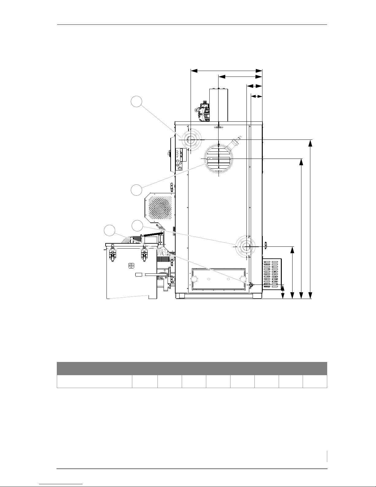
4 Planning and installation – Connections
41
DIMENSIONS OF THE FLUE PIPE SIDE OF THE HDG COMPACT 99 - 115
1 Boiler supply connection (DN 65 flange)
2 Flue pipe connection Ø 250 mm
3 Boiler supply connection (DN 65 flange)
4 Filling / draining connection (DN 15, inside thread)
Figure 4/8 - Dimensions of the flue pipe side of the HDG Compact 99 - 115
A
C
F
G
H
B
D
E
3
2
1
4
A B C D E F G H
HDG Compact 99 - 115 640 390 140 104 1420 1250 464 124
Table 4/3 - Dimensions of the flue pipe side of HDG Compact 99 - 115 (mm)
Page 42
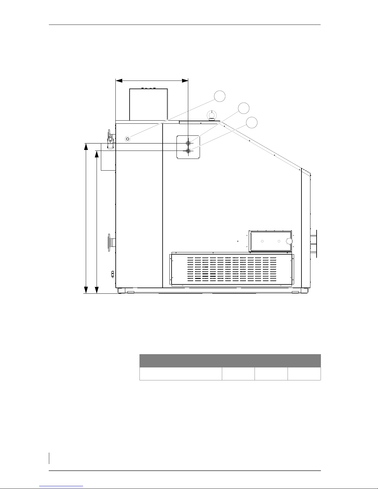
4 Planning and installation – Connections
42
DIMENSIONS OF THE BACK SIDE OF HDG COMPACT 99 - 115
1 Connection of immersion sleeve for thermal safety device (DN 15,
inside thread)
2 Safety heat exchanger inlet (DN 20, inside thread)
3 Safety heat exchanger outlet (DN 20, inside thread)
Figure 4/9 - Dimensions of the back side of HDG Compact 99 - 115
A
B
C
1
2
3
A B C
HDG Compact 99 - 115 666 1374 1304
Table 4/4 - Dimensions of the flue pipe side of HDG Compact 100/105 (mm)
Page 43
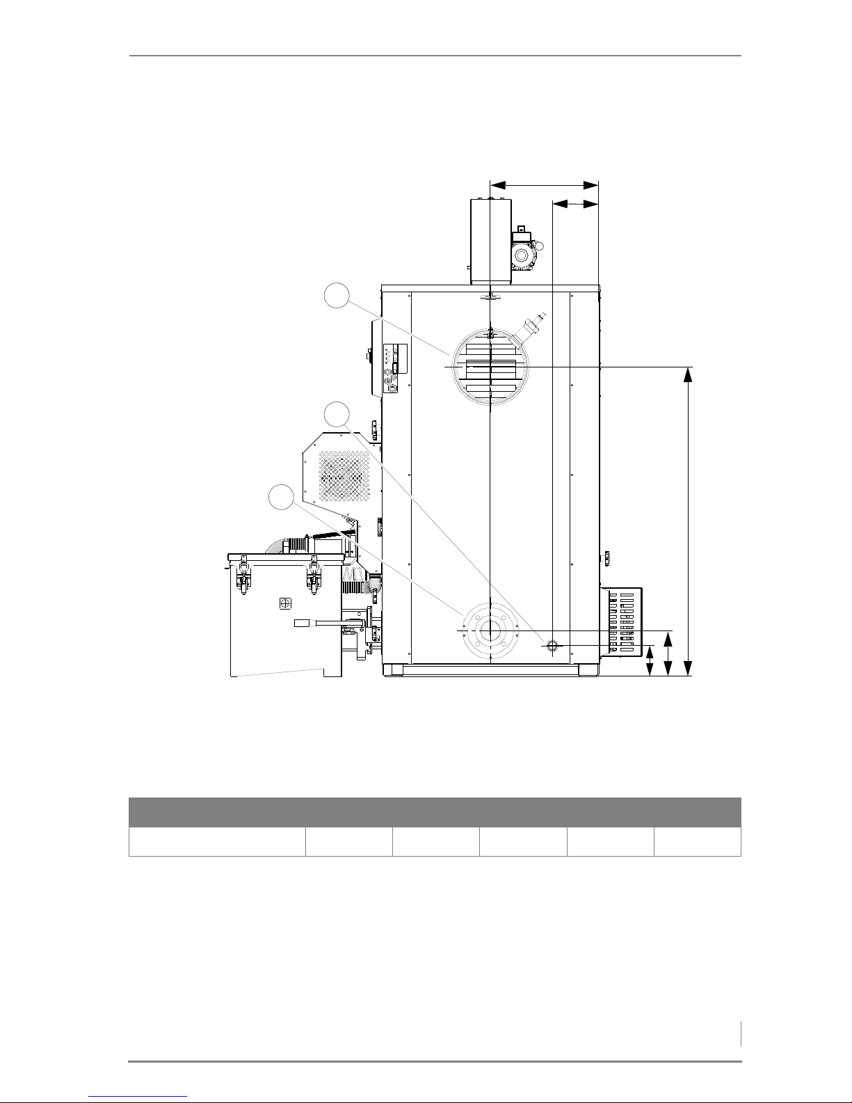
4 Planning and installation – Connections
43
DIMENSIONS OF THE FLUE PIPE SIDE OF THE HDG COMPACT 150 - 200
1 Flue pipe connection Ø 300 mm
2 Filling / draining connection (DN 25, inside thread)
3 Boiler supply connection (DN 80 flange)
Figure 4/10 - Dimensions of the flue pipe side of the HDG Compact 150 - 200
A
B
C
E
D
3
2
1
Model A B C D E
Compact 150 - 200 440 190 1250 184 124
Table 4/5 - Dimensions of the flue pipe side of HDG Compact 150/200 (mm)
Page 44
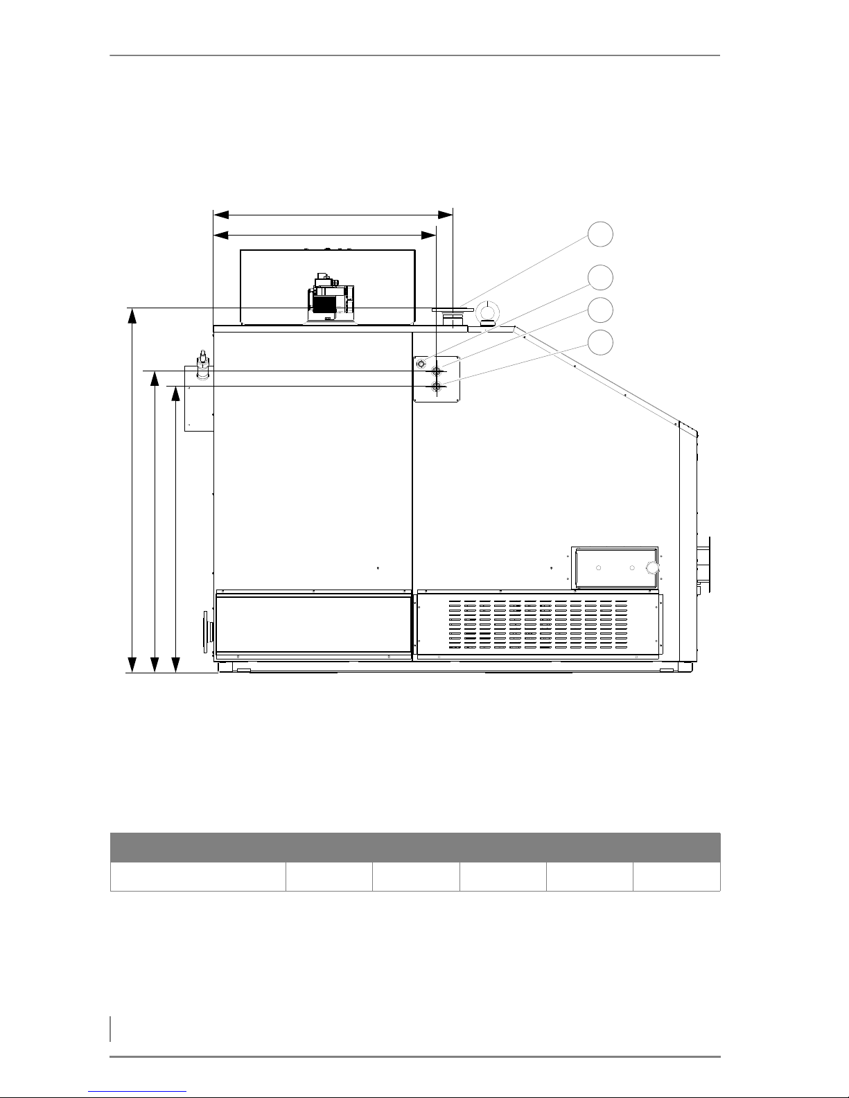
4 Planning and installation – Connections
44
DIMENSIONS OF THE BACK SIDE OF HDG COMPACT 150 - 200
1 Boiler supply connection (DN 80 flange)
2 Connection of immersion sleeve for thermal safety device (DN 15,
inside thread)
3 Safety heat exchanger inlet (DN 20, inside thread)
4 Safety heat exchanger outlet (DN 20, inside thread)
Figure 4/11 - Dimensions of the back side of HDG Compact 150 - 200
A
B
C
D
E
1
2
3
4
Model A B C D E
Compact 150/200 1100 1014 1650 1374 1304
Table 4/6 - Dimensions of the flue pipe side of HDG Compact 150 - 200 (mm)
Page 45
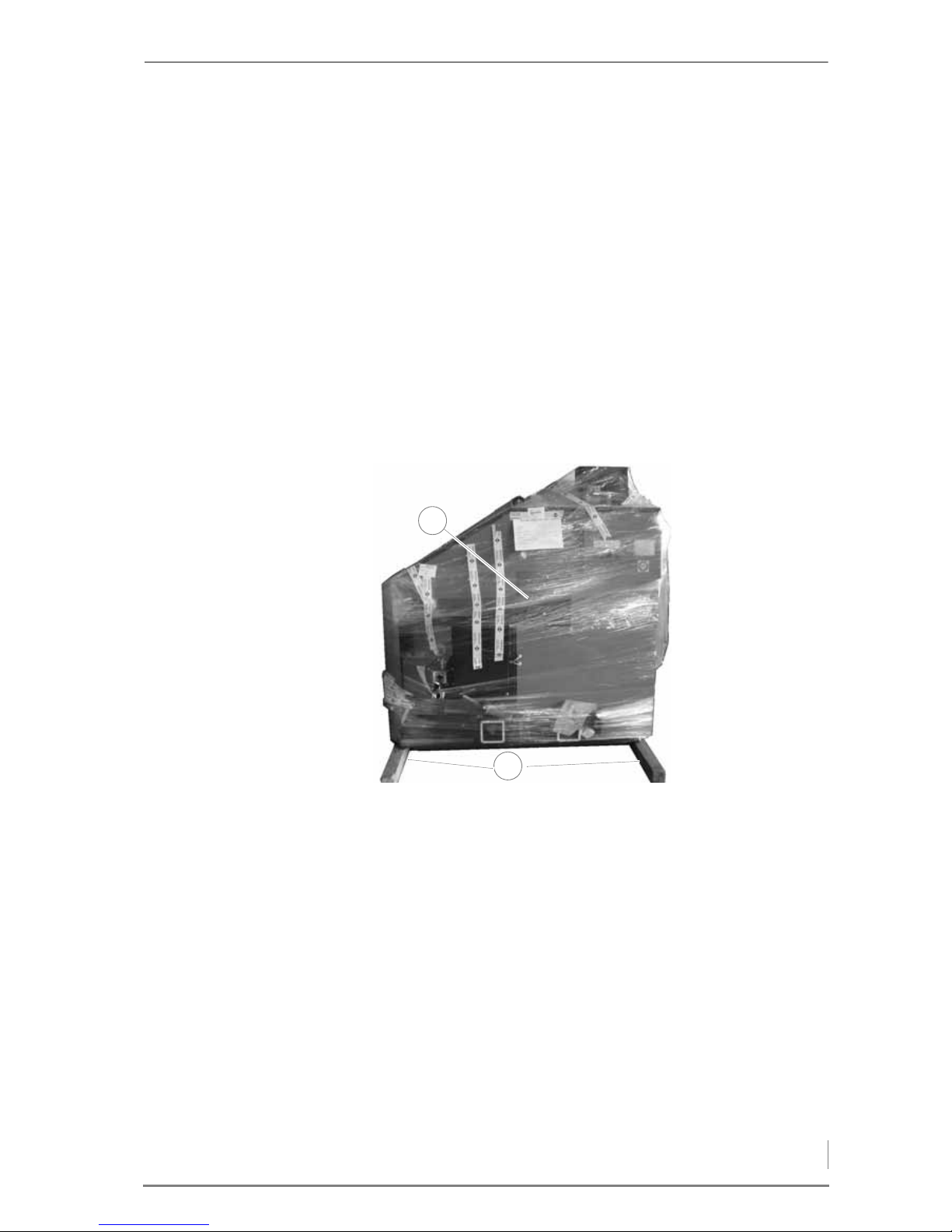
4 Planning and installation – Scope of delivery
45
4.3 Scope of delivery
Included in the scope of delivery:
• HDG Compact 99 - 200 boiler
• Control cabinet model EMD-C 215 Exclusiv
• Feeding system (customer-specific)
• Delivery system (customer-specific)
•Cleaning tools
• Operating documentation
Upon delivery, check that the scope of delivery matches the information on the delivery note.
The heating system HDG Compact 99 - 200 (1) is delivered on two
rectangular wooden planks (2). These wooden planks are intended
only for transportation and should be removed before installing the
system in its planned location.
Figure 4/12 - HDG Compact 100 boiler condition as delivered
1
2
Page 46
4 Planning and installation – Installing the heating system
46
4.4 Installing the heating system
REQUIREMENTS
The heating system will initially be commissioned by specialists from
HDG Bavaria or from an authorised HDG partner and a qualified electrician.
Danger!
Risk of material damage and injury due to incorrect installation
Installing the system requires comprehensive specialist knowledge.
If installed by untrained persons, the heating system can be damaged and persons may be injured due to secondary damage.
Only allow authorised specialists to perform the installation.
Danger!
Dangerous electrical current or voltage
Working on live components can result in an electric shock.
Switch off the mains supply to the heating system during the installation.
Important!
When laying the pipelines, observe the minimum required clearances.
✎ See section “4.1 Planning the heating system” in this chapter.
Important!
Due to the noise, we recommend acoustic insulation measures for
components which are in contact with the floor, wall or ceiling of
the heating room.
The following figures and diagrams show the version of the heating
system HDG Compact 99 - 200 with the feeding system TBZ 150 on
the left side of the boiler.
Please keep this in mind if your version has a feeding system on the
right.
Page 47
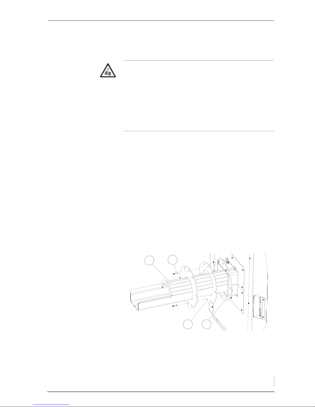
4 Planning and installation – Installing the heating system
47
PLACING THE BOILER
TRANSPORT
There are several options for transporting the HDG Compact 99 - 200
boiler. It can be performed with a crane, forklift or a lifting truck.
I
NSTALLATION SITE 1. Transport the boiler using suitable lifting equipment.
2. Place the boiler at the planned location while observing the mi-
nimum clearances.
✎ See section “4.1 Planning the heating system”, paragraph “Re-
quired room sizes and minimum spacing” in this chapter.
3. Align the boiler with plastic plates or flat steel strips (not included
in the scope of delivery) so that it is horizontal.
4. Unscrew the ring bolt from the boiler.
✓ The boiler has been set up.
INSTALLING THE FEEDING SYSTEM
ATTACHING THE ADAPTER PIPE
1. Slide the adapter pipe (1) with the seal (3) into the
feed channel (4).
2. Align the seal (3) with the holes.
3. Poke a hole through the seal (3) for the centring screw (2).
Warning!
Danger from suspended loads
The boiler weighs over 1000 kg. If the boiler is dropped during
transport, persons can be seriously injured and the boiler can be damaged.
Make sure that you use appropriate lifting gear when placing the
boiler.
Ensure that the chain hoist is correctly secured to the eyebolt of the
boiler during crane transport of the heating system.
Figure 4/13 - Attaching the adapter pipe
4
1
3
2
Page 48
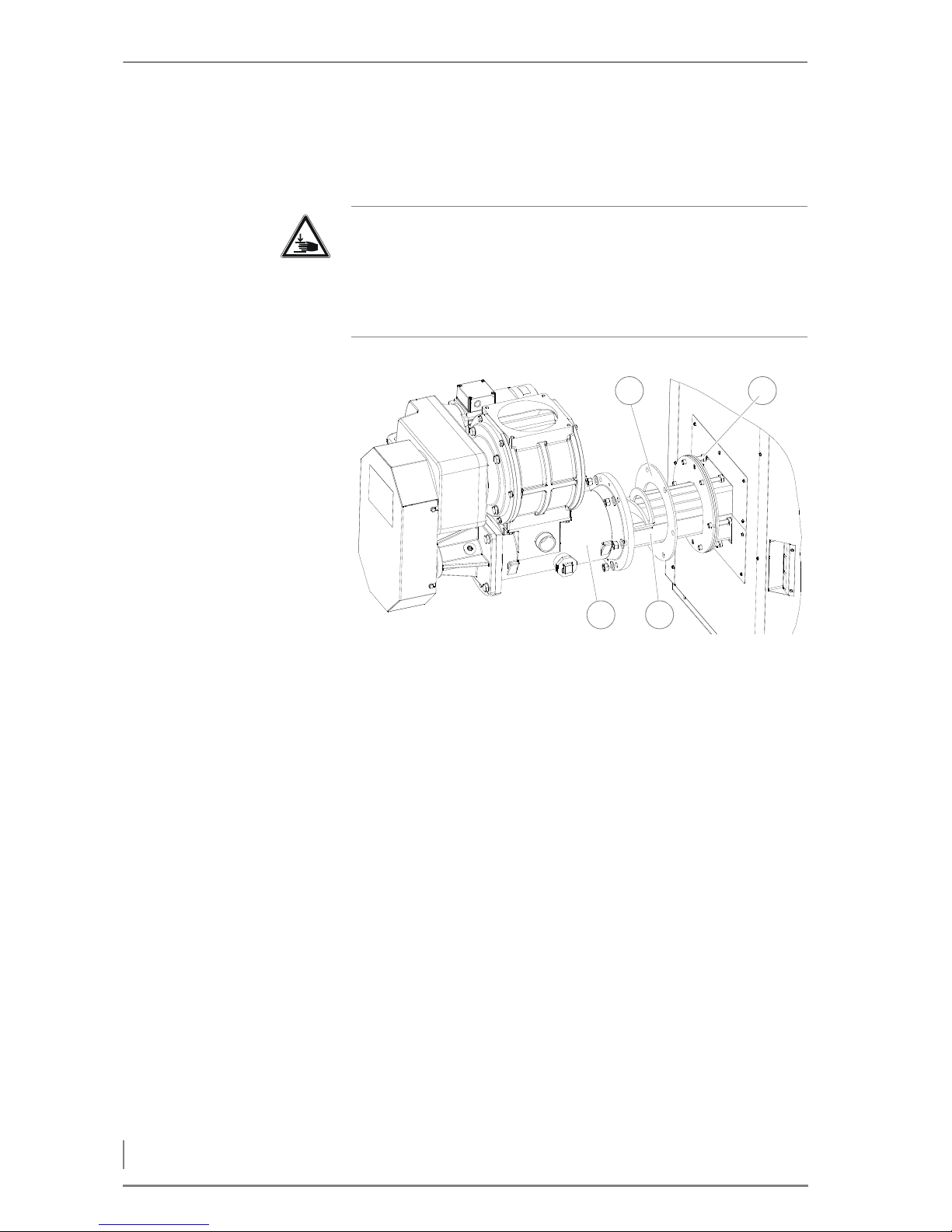
4 Planning and installation – Installing the heating system
48
4. Insert the centring screw (1) toward the boiler through the holes
and screw it tight with the M6 nut using a 10 mm spanner.
A
TTACHING THE FEEDING
SYSTEM
5. Insert the M12 screws (2) from the boiler through the holes.
6. Insert the second seal (1) on the adapter pipe (4).
7. Slide the feeding system (3) onto the adapter pipe (4).
8. Bolt on the feeding system (3) with the M12 nuts using an SW19
spanner.
Warning!
Danger of injury
The feeding system is very heavy. Hands and feet could be crushed
when it is lifted.
Only lift the feed system using suitable lifting equipment.
Figure 4/14 - Attaching the feeding system
4
21
3
Page 49
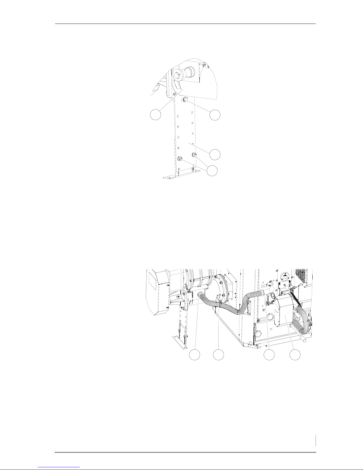
4 Planning and installation – Installing the heating system
49
FITTING THE SUPPORT LEG
✓ The support leg is attached.
C
ONNECTING THE FEEDING
SYSTEM
12.Connect the plug of the feeding system at the appropriate place
on the plug board at the front of the boiler.
✎ See the provided circuit diagram.
✓ The feeding system is connected and mounted.
ATTACHING THE PRESSURE EQUALISATION HOSE
1. Place the rubber seal on the connections of the pressure equalisa-
tion hose (2).
2. Attach the union nuts DN 32 to the feed system (1) and the boiler
(3).
✓ The pressure equalisation hose is connected.
3. Remove the servo motor cover (4).
9. Bolt the support leg (3) with
an M12 screw (2) onto the feeding system (1) using an
SW19 spanner.
10.Fix the support leg (3) to the
floor as required (screws and
screw anchors are not included in the scope of delivery).
11.Align the feeding system (1)
horizontally with the two M10
screws (4).
Figure 4/15 - Fitting the support leg
1
3
1
2
4
Figure 4/16 - Attaching the pressure equalisation hose
A
u
f
Z
u
21 3 4
Page 50
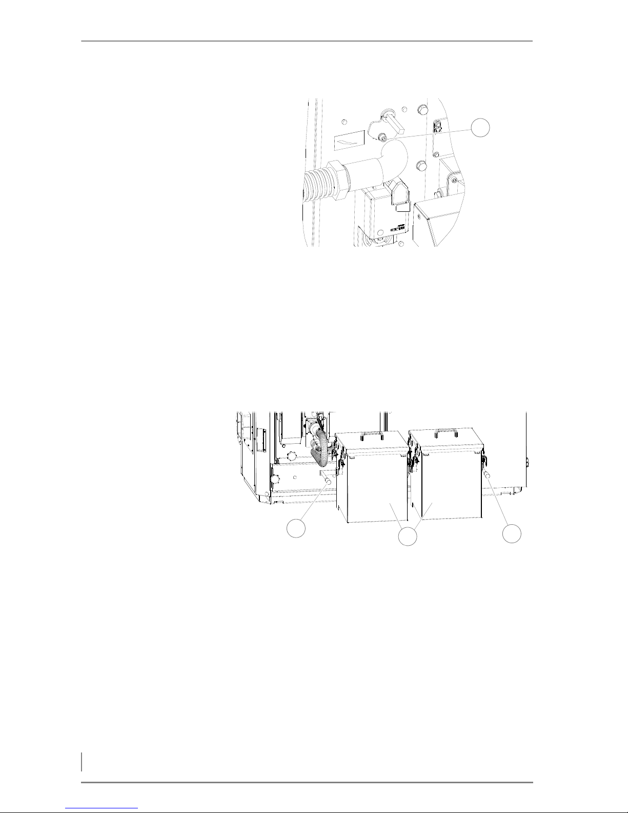
4 Planning and installation – Installing the heating system
50
4. Set the position indicator (1) for the pressure equalisation regulator to approximately “Half open” using a 5 mm hexagon socket
screw.
5. Fit the servo motor cover.
✓ The pressure equalisation regulator is set.
INSTALLING ASH CONTAINER(S)
ASH CONTAINER 80 L 1. Remove the ash containers from the packaging.
2. Lift up the two clamp handles (1, 3).
3. Insert the ash containers (2) on the ash removal pipe.
4. Press the clamp handles downward.
✓ Grasp the clamp handles and press the ash containers against the
seal of the ash removal door.
5. If the clamp handles do not clamp, adjust them as follows.
Figure 4/17 - Setting the pressure equalisation regulator
A
u
f
Z
u
1
Figure 4/18 - Installing ash container(s)
3
2
1
Page 51
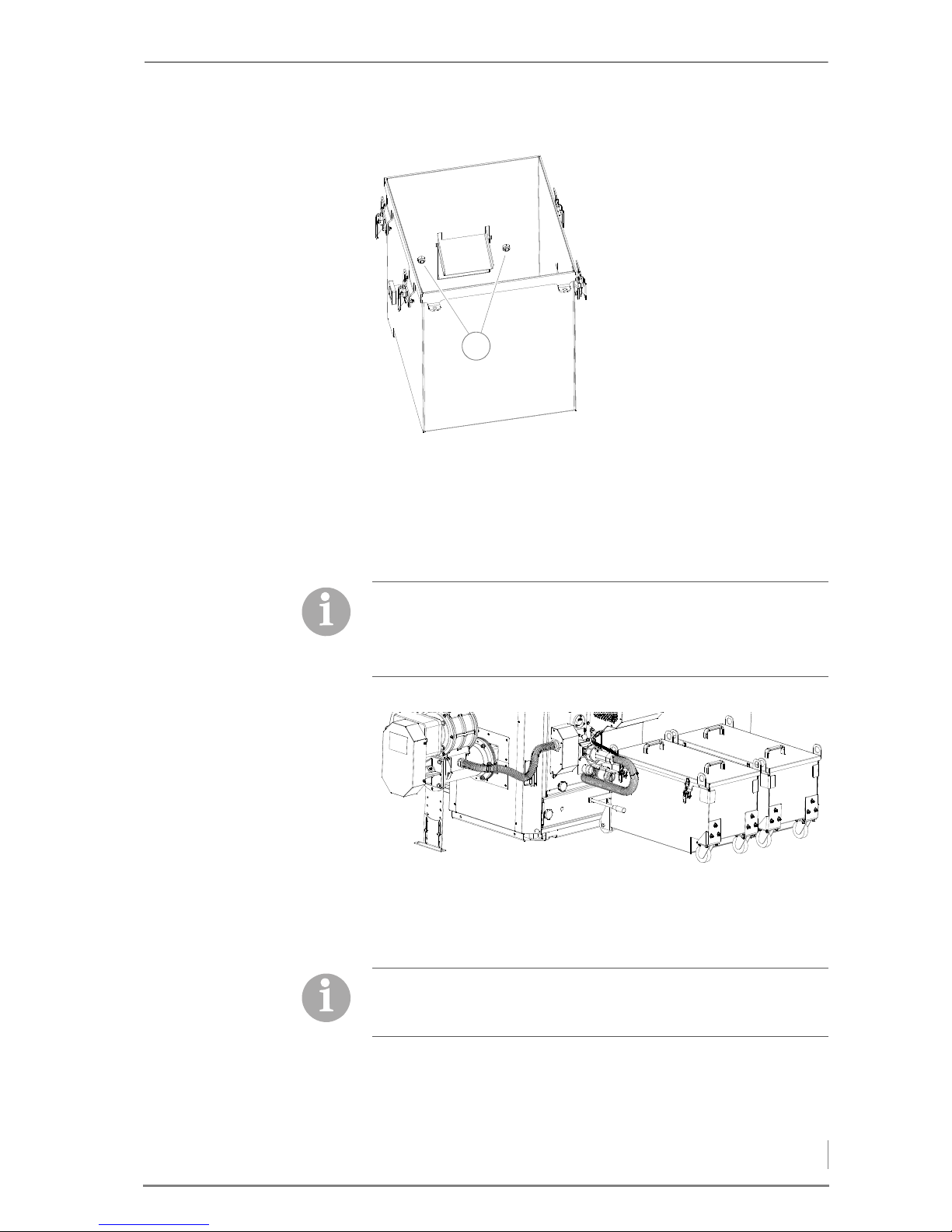
4 Planning and installation – Installing the heating system
51
✓ Grasp the clamp handles and tighten the ash containers solidly on
the ash removal door.
5. Close the ash containers in the reverse sequence.
✓ The ash containers are mounted and adjusted.
A
SH CONTAINER 140 L
INSTALLING THE CENTRAL ASH REMOVAL SYSTEM
1. Remove the cover from the
ash container.
2. Release the external nuts on
the ash container.
3. Adjust the ash container with
the interior nuts (1) until the
clamping handles latch firmly.
4. Screw on the nuts and check
that the clamp handles clamp
firmly.
Figure 4/19 - Adjusting the ash containers
1
Optionally, for the HDG Compact 99 - 200 heating system 140 l ash
containers can be installed instead of 80 l ash containers.
Installation and adjustment is performed in the same way as with
the 80 l ash containers.
Figure 4/20 - Ash container 140 l
For the HDG Compact 99 - 200 heating system, a central ash removal system is optionally available for delivering the combustion
ash and fly ash to a 240 l ash bin.
Page 52
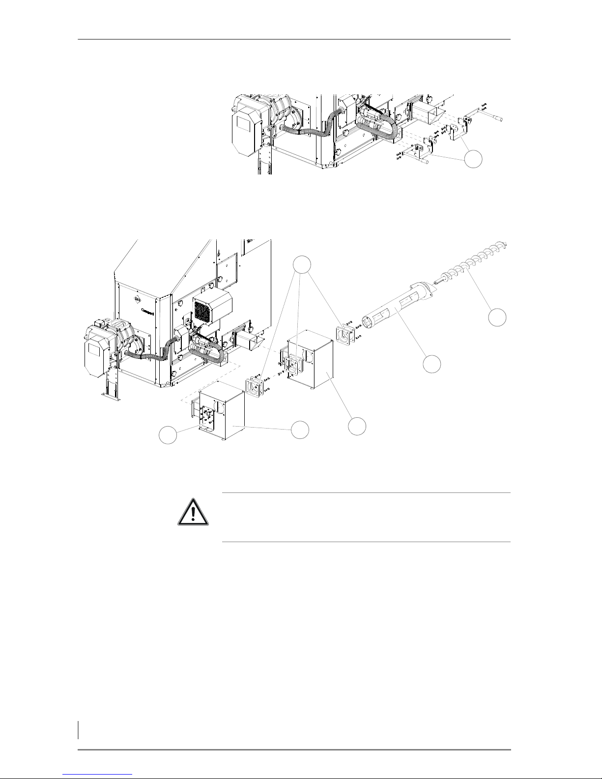
4 Planning and installation – Installing the heating system
52
1. Remove both clamping devices (1) from the ash removal doors
using an SW13 spanner.
2. Push the auger trough (5) through the flange plates (1) and seals
into the ash accumulation bins (3, 4).
3. Install the flange plates (1) with the M10 screws (spanner size
SW17) and washers on the ash accumulation bins (3, 4).
4. Install the torque support (2) using the M10 hexagon socket
screws (spanner size SW6) on the ash accumulation bin (3).
5. Install the auger trough (5) using the M8 hexagon socket screws
(spanner size SW5) on the torque support (2).
6. Push the ash removal auger (6) through the auger trough (5).
Figure 4/21 - Removing clamping devices
1
Figure 4/22 - Pre-assembling the central ash removal system
6
5
3
2
1
4
Important!
Then secure all screws for the assembly of the central ash removal
system, without tightening them.
Page 53
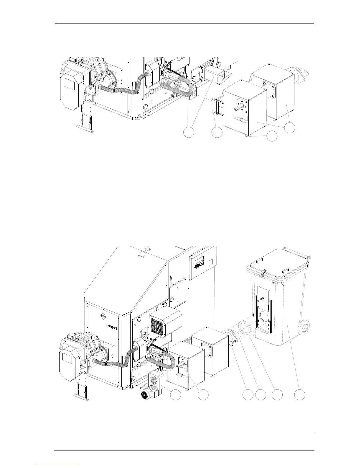
4 Planning and installation – Installing the heating system
53
7. Push both ash accumulation bins (4) onto the door necks of the
ash removal doors (1).
8. Use the spacers (2) during installation of the ash accumulation
bins (4).
9. Install the ash accumulation bins (4) on the ash removal doors (1)
with the M12 screws and nuts (spanner size SW19) and washers.
10.If necessary, compensate for any unevenness on the floor with the
aid of the adjustable legs (3) on the ash accumulation bins (4).
11.Tighten all the screws on the central ash removal system.
12.Insert the feather key (2) into the ash removal auger.
Figure 4/23 - Installing the ash accumulation bins
2
4
1
3
Figure 4/24 - Installing the motor and ash bin
2 651 3 4
Page 54
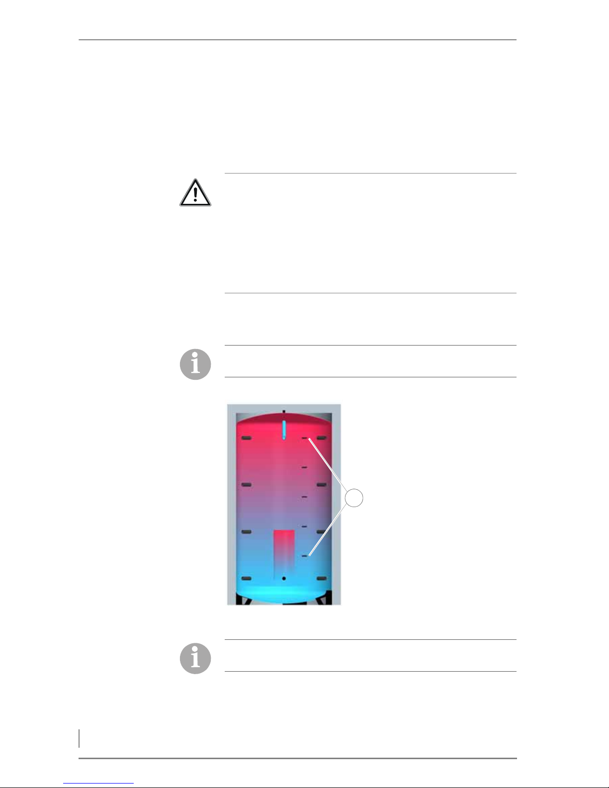
4 Planning and installation – Installing the heating system
54
13.Install the drive motor (1) on the ash removal auger using the M8
screw (spanner size SW13) including the spring ring and washers.
14.Slide the ash bin (6) with the intermediary seal (5) onto the auger
trough (4).
15.Secure the ash bin (6) using the star-grip screws (3).
✓ The central ash removal system is now installed.
FITTING THE BUFFER PROBE
✓ The sensors are installed.
Caution!
Material damage and injury due to burn-back or smoke
If the ash accumulating bins are not at least half-filled when commissioning or re-starting after a cleaning, there is a danger of backfiring or smoke from the boiler. This can cause damage to the
heating system or injury to persons.
Make sure that both ash accumulation bins (1) are at least half-filled
with ash, sand, etc.
The sensors for the buffer tank are in the EMD-C 215 Exclusiv control
cabinet for further use.
1. Seal the immersion sleeves of
the sensors with a suitable
sealing material and position
them at the points indicated
in the figure 4/25.
2. Guide the sensors into the immersion sleeves.
3. Insert the prefabricated plug
connections into the terminals specified in the circuit
diagram.
Figure 4/25 - Installing the sensors
1
For a hydraulic diagram without buffer tank, these sensors are not
present and must be taken out of the corresponding parameters.
Page 55

4 Planning and installation – Delivery system
55
INSTALLING THE EMD-C 215 EXCLUSIV CONTROL CABINET
Observe the following when installing the EMD-C 215 Exclusiv control cabinet:
• The HDG Compact 99 - 200 heating system is supplied with a 10 m
cable for connecting the boiler with the control cabinet. Install the
control cabinet within range of the connection cable.
• Install the control cabinet at least one metre from the flue pipe.
• Prevent the control cabinet from tipping by fixing it to the wall securely.
• If possible, install the control cabinet in such a way that you can
see boiler when operating the control panel of HDG Control.
• Install the control cabinet at a height comfortable for you to operate.
CONNECTING THE CHIMNEY
✎ See section “4.2 Connections” in this chapter.
1. Connect the flue pipe to the chimney connection or with the HDG
cyclone dust extractor.
2. Make sure that the connecting piece does not protrude into the
chimney.
3. Seal the connection to the chimney with highly fireproof silicone
or with a suitable mortar.
✓ The boiler is now connected to the chimney.
4.5 Delivery system
GENERAL INFORMATION
The description for planning, installation and operation of the employed delivery system can be found in the corresponding operating
manual.
✎ See the operating manual, "Delivery system".
Warning!
Danger of injury
The control cabinet is heavy. Hands and feet could be crushed during installation.
Page 56
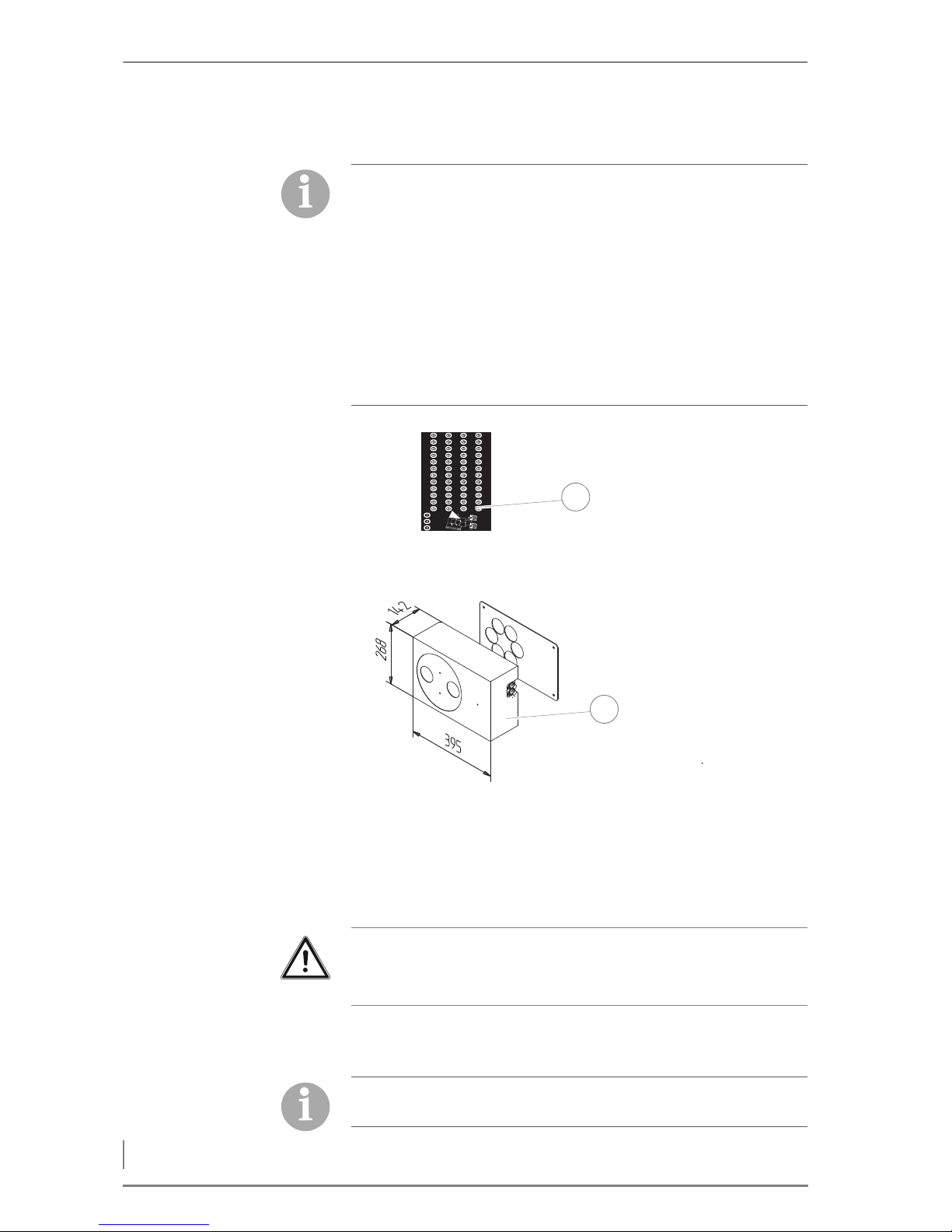
4 Planning and installation – Delivery system
56
HDG HOSE JUNCTION
SCOPE OF DELIVERY
1 Hose junction incl. cover plate
2 Label for inscription
G
ENERAL INFORMATION The HDG hose junction can be installed on a wall or free-standing
with the stand.
Using the stand, the hose junction can be installed free-standing in
the room.
L
ABEL
In order to combine several HDG PSS or FRA-PSS pellet delivery systems on an HDG pellet vacuum container, the HDG hose junction
can be used. It is positioned between the transfer stations of the PSS
augers and pellet vacuum container.
Accordingly, installation of the hose junction is performed after installation of the vacuum and return hose on the transfer station of
the PSS auger.
✎ See the operating manual for the HDG pellet delivery system PSS
or FRA-PSS and the HDG pellet vacuum system, chapter 4 "Planning and Installation", section 4.5 "HDG pellet vacuum system",
paragraph "Installing the vacuum and return hose".
Figure 4/26 - Accessories for delivery system with suction sensors
05/2010 007057/01
1
2
Important!
The hose junction must be installed using the supplied metal dowels in such a way as to ensure problem-free access from outside.
The vacuum hoses are labelled A1, A2 or A3, and the return hoses
B1, B2 or B3, depending on the number of pellet augers.
Page 57
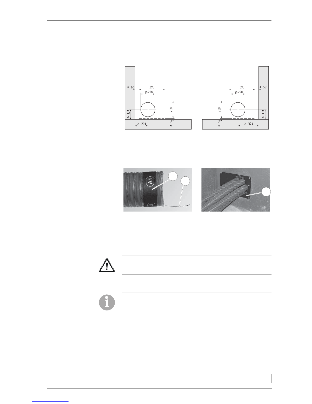
4 Planning and installation – Delivery system
57
WALL PENETRATION A wall penetration of ca. 220 mm is necessary to mount the hose
junction on a wall.
I
NSTALLATION 1. Mount the cover plate provisionally on the interior wall using the
dowels, diameter 8 mm, and the provided screws.
2. Expose the earthing lead (2) at the hose end.
3. Label the hose end with the provided A1 label (1).
4. Insert the hose end through the A1 opening in the cover plate (3)
until the outside of the hose is flush with the wall.
5. Proceed with hoses A2, A3 or B1, B2, B3 exactly as described
above.
Figure 4/27 - Wall penetration for hose junction
Figure 4/28 - Cutting and laying hose
2
3
1
Important!
Observe the minimum bending radius of 30 cm.
For easier hose mounting, the hose junction should be at the same
height as the hose (e.g. support with wooden boards).
Page 58
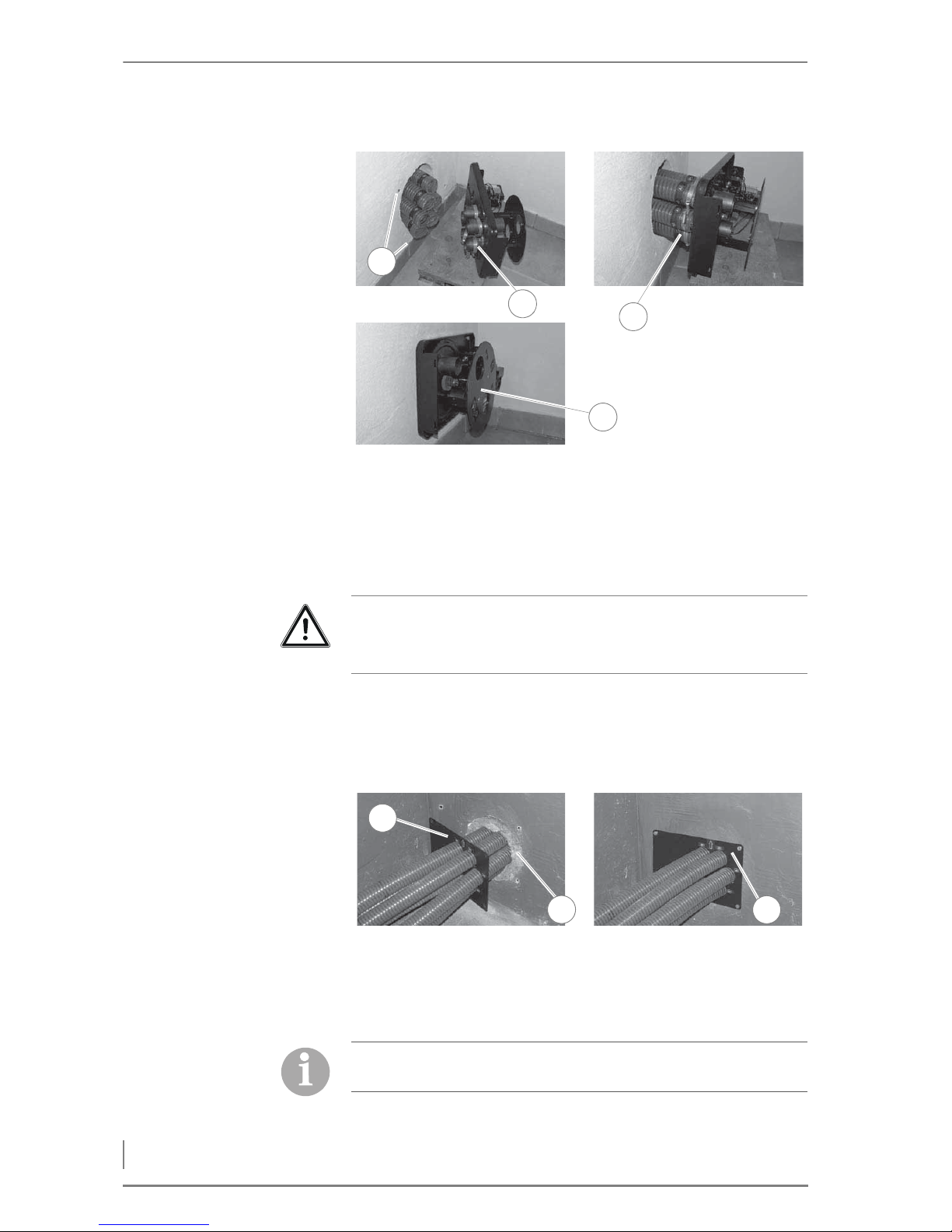
4 Planning and installation – Delivery system
58
6. Drill the mounting holes (1) for the metal dowels, diameter 10
mm, in the wall.
7. Remove the cover on the front of the hose junction.
8. Place the hose clamps (2) over the connection nozzles of the hose
junction.
9. Place the labelled hoses (3) on the hose junction connections.
10.Secure the hoses (3) with the aid of the hose clamps.
11.Mount the hose junction (4) on the wall.
12.Dismantle the cover plate (1) in the storage room.
13.Fill the wall penetration with mineral wool (2).
14.Mount the cover plate (3) on the wall.
Figure 4/29 - Installing hose on hose junction
Fig. 1-10 Schlauchklemmen aufstecken Fig. 1-11 Schläuche mit Schlauchklemmen b
e
gen
3
1
2
4
Important!
The earthing leads in the hoses must be in contact with the connection nozzles!
Figure 4/30 - Installing the cover plate
3
1
2
We recommend laying the vacuum and return air hose between the
hose junction and the boiler in Polokal pipes.
Page 59
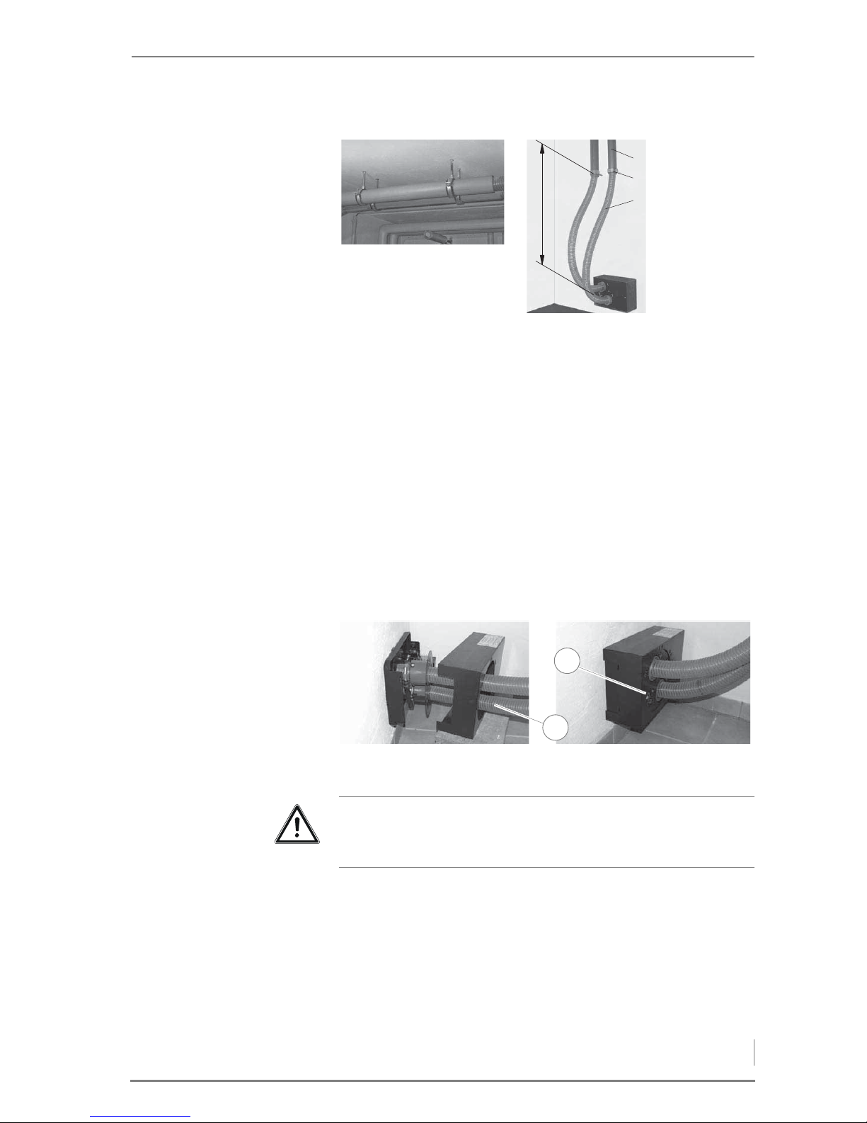
4 Planning and installation – Delivery system
59
1) Polokal pipes 80 mm
2) Do not clamp hoses in a fixed position
3) Hose length up to first attachment min. 1450 mm
The hoses must be long enough for the hose junction and may not
be attached in a fixed position (hoses are rotated 180°). Distance and
hose length to the initial attachment must be upheld.
15.Adapt the length of the vacuum and return air hoses.
16.Expose the earthing lead at the hose end ca. 5 cm.
17.Bend the earthing lead inward.
18.Label both hoses with the provided A and B labels.
19.Place the hose clamps on the hose junction connections.
20.Place the labelled hoses (1) on the hose junction connections.
21.Secure the hoses (1) with the aid of the hose clamps.
22.Replace the cover (2) on the hose junction.
✓ The HDG hose junction is now installed.
Figure 4/31 - Vacuum and return air hose in Polokal pipes
Fig. 1-20 Förderschläuche in Polokalrohr
1000 mm
1
2
3
Figure 4/32 - Connecting the suction and return hoses
1
2
Important!
The earthing leads in the hoses must be in contact with the connection nozzles!
Page 60

4 Planning and installation – HDG cyclone dust extractor
60
✎ For further procedures in the attachment of the hoses, see the
operating manual for the HDG pellet delivery system PSS or FRAPSS and the HDG pellet vacuum system, chapter 4 "Planning and
Installation", section 4.5 "HDG pellet vacuum system", paragraph
"Installing the vacuum and return hose".
4.6 HDG cyclone dust extractor
✎ All information and instructions regarding the functioning, instal-
lation, start-up, maintenance/cleaning etc. can be found in the accompanying "Operating and Maintenance Manual for the HDG
Cyclone Dust Extractor".
U
NDERPRESSURE CONTROL Optionally available is an HDG underpressure control with frequency
converter and differential pressure transmitter for adaptation to
changing chimney conditions. It creates an automatic adjustment to
the underpressure required with output and combustion control and
thereby improves the of the partial load capacity of the system.
✎ See the "HDG underpressure control" manual.
4.7 Electrical system
The electrical connections must be made in accordance with DIN IEC
60364 “Setting up low-voltage electrical installations”.
✎ The technical details are described in the chapter “3 Mode of ope-
ration”, section “3.3 Technical data”.
1. Install the electrical connections in accordance with the provided
circuit diagrams.
✎ The circuit diagrams can be found in the supplied documentation.
4.8 Water
The heating system must be filled with water in accordance with VDI
guideline 2035, “Avoiding damage in hot water heating systems”.
The diaphragm expansion vessel must be constructed in accordance
with DIN EN 13831 “Closed expansion vessels with built-in diaphragm for integration in water installations”.
Before putting the system into operation, the pressure of the diaphragm expansion vessel must be adjusted for the conditions in the
heating system and in the building.
After putting the system into operation, heat up the system to the
maximum boiler temperature and bleed air from the system again to
make sure that there are no air pockets.
Page 61
4 Planning and installation – Thermal safety device
61
The safety devices must be implemented in accordance with DIN EN
12828 “Heating systems in buildings” and the correspondingly harmonised national standard DIN 4751, Part 2 “Closed, thermostatically
safeguarded heat generating systems with supply temperatures of
up to 120 °C; safety equipment”.
In Germany, the requirements of the German energy conservation
ordinance (EnEV) are to be met.
4.9 Thermal safety device
In accordance with DIN EN 12828, heating systems must be
equipped with safety devices to prevent the maximum operating
temperature from being exceeded. The safety heat exchanger serves
to protect the boiler against overheating and may not be used for
other purposes (i.e. as a regular heat exchanger). If the heat transfer
capacity is suddenly lost (for example if the circulation pump for raising the return temperature fails), heat production cannot be
stopped as quickly as with an oil- or gas-fired boiler. When the maximum operating temperature is exceeded, the thermal safety device
(TAS) is triggered and cold water flows through the safety heat exchanger. The excess energy generated is thus dissipated by the
“emergency cooling”. (This is an alternative to fast regulation.)
However, the safety heat exchanger and thermal safety device can
only serve their purpose if the following requirements have been
met:
• A flow pressure of at least two bar and a flow rate of 1800 l/h must
be available at the cold water inlet of the safety heat exchanger.
• The distance between the supply and return lines of the thermal
safety device and the safety heat exchanger should be less than
their nominal width. The supply line may not be equipped with a
shut-off valve.
• Water must be able to flow freely through the system.
• The flow pressure at the flue connection on the boiler may not si-
gnificantly exceed the prescribed value.
The thermal safety device must be installed according to guidelines
from HDG Bavaria.
Mains-dependent, stand-alone supply systems are not safe enough
due to dependence upon the power supply!
The thermal safety device is to be inspected annually by an authorised, qualified technician to verify that it is functional.
Important!
In order to prevent leaks, avoid turning the connections of the safety heat exchanger anticlockwise when installing the thermal safety device.
Page 62
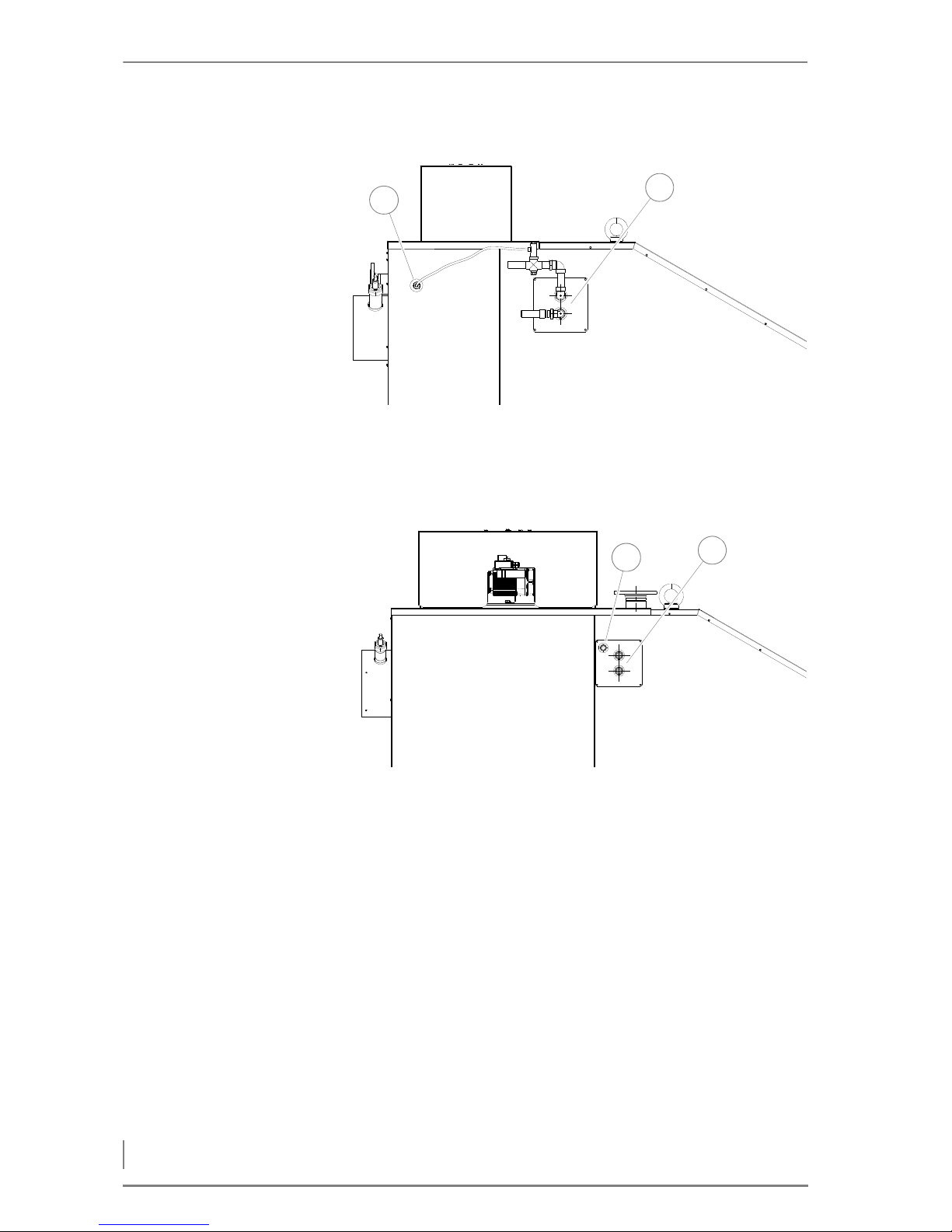
4 Planning and installation – Thermal safety device
62
HDG COMPACT 99 - 115
1 Connection of immersion sleeve for thermal safety device (DN 15
female)
2 Safety heat exchanger connections (DN 20, inside thread)
HDG C
OMPACT 150 - 200
1 Connection of immersion sleeve for thermal safety device (DN 15
female)
2 Safety heat exchanger connections (DN 20, inside thread)
Figure 4/33 - Installing the HDG Compact 99 - 115 thermal safety device
1
2
Figure 4/34 - Installing the HDG Compact 150 - 200 thermal safety device
1
2
Page 63
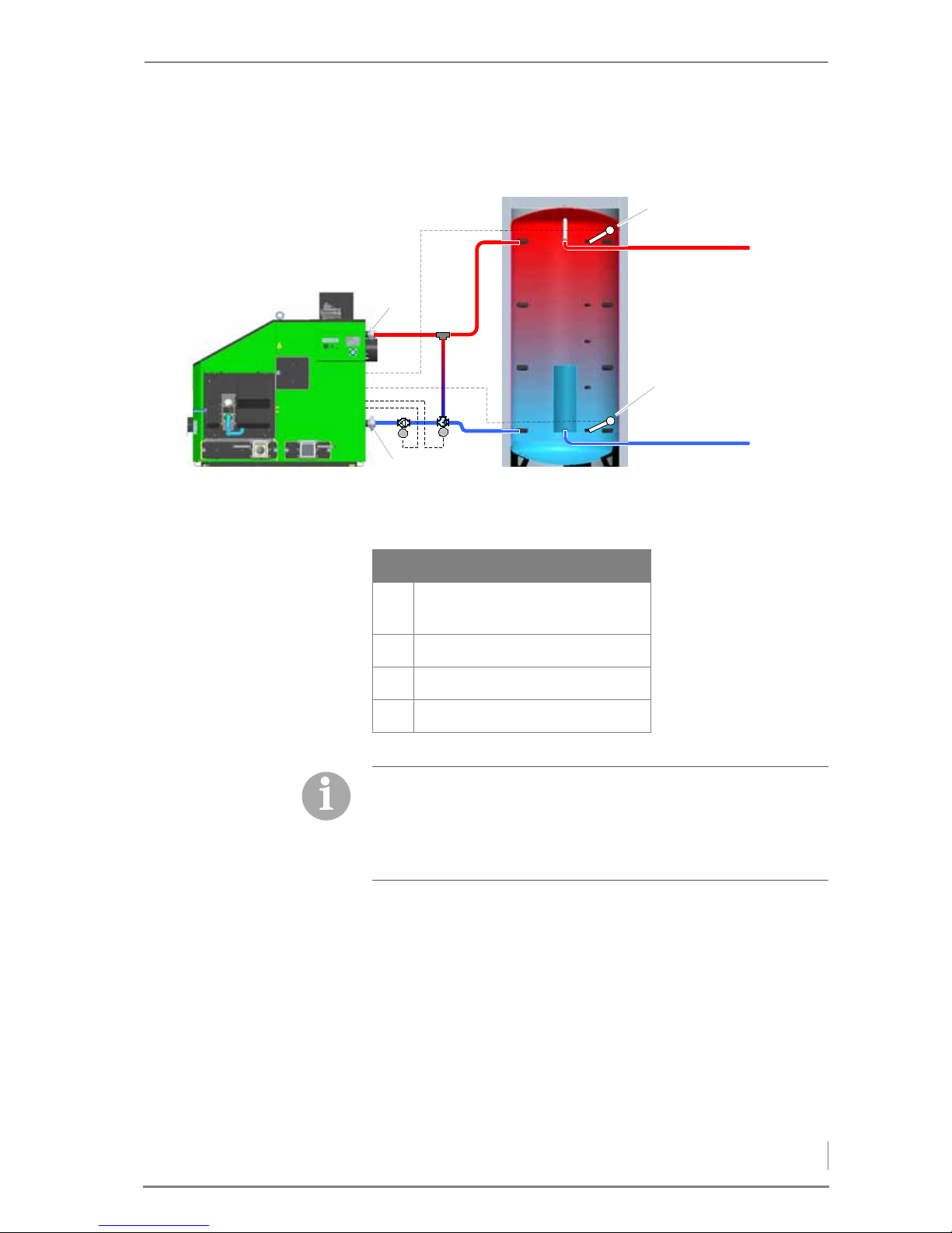
4 Planning and installation – Hydraulic system
63
4.10 Hydraulic system
Figure 4/35 - Hydraulic system
0
0
At
Ab
RT
ST
HDG Control
ST Supply temperature sensor (boi-
ler temperature)
RT Return temperature sensor
At Acc. top
Ab Acc. bottom
The hydraulic system is only suitable for the indicated purpose and
in the specified manner. Any deviation from this usage could make
adjustments necessary.
Consult with a trained specialist on issues relating to the hydraulic
system.
Page 64
5 Commissioning the system – Requirements
64
HDG Compact 99 - 200 - Version 1 - en © HDG Bavaria GmbH 07/2008
5 Commissioning the system
The heating system is initially commissioned by specialists from HDG
Bavaria or from an authorised HDG partner.
The commissioning includes an introduction to the operation and
maintenance of the heating system as well as performing measurements on the system to determine exhaust emissions and firing performance.
5.1 Requirements
The following conditions must be met before the system can be commissioned without faults:
S
WITCH OFF THE MAINS SUPPLY • Is the circuit breaker of the mains supply to the heating system
switched off?
C
HECK THE MECHANICAL
STRUCTURE OF THE FEEDING
SYSTEM
• Does the mechanical structure meet the specifications of this ope-
rating manual?
C
HECK THE HYDRAULIC
CONNECTIONS
• Do the mechanical connections meet the specifications of this
operating manual?
• Has the safety equipment been installed to conform to the appli-
cable standards and guidelines?
C
HECK THE MECHANICAL
STRUCTURE OF HDG COMPACT
• Does the mechanical structure meet the specifications of this ope-
rating manual?
Danger!
Material damage and injury due to incorrect commissioning
Commissioning the system requires comprehensive expertise. If
this commissioning is done by an untrained person, the heating
system could be damaged.
Only allow authorised specialists to perform the commissioning.
Page 65
© HDG Bavaria GmbH 07/2008 HDG Compact 99 - 200 - Version 1 - en
5 Commissioning the system – Procedure
65
CHECK THE ELECTRICAL
CONNECTIONS
• Are all the sensors and actuators connected correctly?
• Has the mains power supply cable been correctly connected?
–L1 on terminal X11
–L2 on terminal X12
–L3 on terminal X13
– Neutral conductor on terminal X14
– Earthing conductor on terminal X15.
• Are the connection cables properly attached between the boiler
and the control cabinet?
5.2 Procedure
SWITCHING ON THE HEATING SYSTEM
1. Turn the heating system main switch on.
✓ The control is activated.
✓ After a start-up phase, the display will first of all show a switch-on
message and then the standard display.
2. Set the engage switch to “1”.
✓ The display switches to Heating ON.
✓ The heating system is now switched on.
SETTING THE DISPLAY LANGUAGE
Different languages can be set for the display texts.
✎ See the chapter entitled “6 Using the heating system”, section
“6.5 Calling up information, selecting and modifying parameters”.
CHECKING THE ACTUATORS IN MANUAL OPERATION
In the MANUAL menu you can manually test the functionality of all
actuators, e.g. drive motors, fans and electrical mounted parts.
Danger!
Danger from electrical current or voltage!
Isolate the mains cable to the heating system.
Page 66

5 Commissioning the system – Procedure
66
HDG Compact 99 - 200 - Version 1 - en © HDG Bavaria GmbH 07/2008
COMBUSTION AIR AND IGNITION
FAN
The fans can be activated manually in this sub-menu.
✎ See chapter “6 Using the heating system”, section “6.9 MANUAL
menu”, paragraph “Combustion air and ignition fan”.
A
SH REMOVAL, MAIN CLEANING,
DUST REMOVAL AND CLEANING
SYSTEM
In this submenu, the grate with the ash removal auger, main
cleaning, dust removal and cleaning system can be activated manually.
✎ See chapter “6 Using the heating system”, section “6.9 MANUAL
menu”, paragraph “Ash removal, main cleaning, dust removal and
cleaning system”.
B
ACKFLOW PUMP AND
BACKFLOW VALVES
This submenu is used to activate the return pump and return mixing
valve.
✎ See chapter “6 Using the heating system”, section “6.9 MANUAL
menu”, paragraph “Return pump and return mixing valve”.
F
EEDING AND METERING This submenu is used to manually activate the feeding and metering
from the wood fuel product bunker.
✎ See chapter “6 Using the heating system”, section “6.9 MANUAL
menu”, paragraph “Feeding and dosage”.
F
EEDING, METERING AND
EXTRACTION
In this submenu, the feeding and the delivery system can optionally
be activated together with the dosing auger lying in between.
✎ See chapter “6 Using the heating system”, section “6.9 MANUAL
menu”, paragraph “Feeding, dosage and delivery system”.
F
EEDING, METERING, VACUUM
FAN AND DELIVERY SYSTEM
In this submenu, the feeding, vacuum fan and delivery system can
optionally be activated together with a dosing auger lying in between.
✎ See chapter “6 Using the heating system”, section “6.9 MANUAL
menu”, paragraph “Feeding, metering, vacuum fan and delivery
system”.
H
OSE JUNCTION AND PELLET
AUGER
This submenu is used to manually activate the hose junction and corresponding pellet auger.
✎ See chapter “6 Using the heating system”, section “6.9 MANUAL
menu”, paragraph “Hose junction and pellet auger”.
Danger!
Material damage and injury due to incorrect operation.
Activating the following parameters requires comprehensive technical expertise. If the parameters are not activated by trained personnel, the heating system can be damaged and dangerous
operating conditions can arise.
Page 67
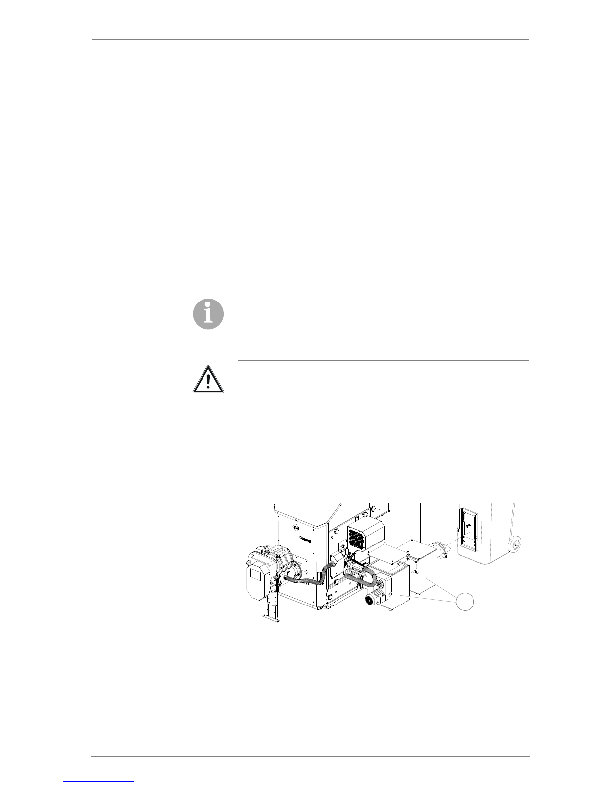
© HDG Bavaria GmbH 07/2008 HDG Compact 99 - 200 - Version 1 - en
5 Commissioning the system – Procedure
67
FEEDING, METERING AND
LATERAL AUGER
In this submenu, the feeding and the transverse auger can optionally
be activated together with the dosing auger lying in between.
See chapter “6 Using the heating system”, section “6.9 MANUAL
menu”, paragraph “Feeding, metering and lateral auger”.
S
LIDING TRAY This submenu is used to manually activate the drive of the moving
floor (if installed).
✎ See chapter “6 Using the heating system”, section “6.9 MANUAL
menu”, paragraph “Moving floor”.
Once the functionality of all the actuators is checked in manual operation, the HDG Compact 99 - 200 heating system can be operated in
accordance with the set control mode.
FILLING THE ASH ACCUMULATION BIN
1. When commissioning the system, make sure that both ash accu-
mulation bins (1) are at least half-filled with ash, sand, etc.
The following section is only relevant when operating theHDG
Compact 99 - 200 heating system with a central ash removal
system.
Caution!
Material damage and injury due to backfiring or smoke
If the ash accumulation bins are not at least half-filled when commissioning or re-starting after a cleaning, there is a danger of backfiring or smoke from the boiler. This can cause damage to the
heating system or injury to persons.
Make sure that both ash accumulation bins are at least half-filled
with ash or sand.
Figure 5/1 - Filling the ash accumulation bin
1
Page 68
5 Commissioning the system – Procedure
68
HDG Compact 99 - 200 - Version 1 - en © HDG Bavaria GmbH 07/2008
FILLING THE FUEL BUNKER
1. Before filling the fuel bunker, check the rotational direction, the
intermediate base, the leaf springs and the dosing plate of the delivery system.
2. Fill the fuel bunker.
✎ See the chapter entitled “6 Using the heating system”, section
“6.12 Filling the fuel bunker”.
✓ The fuel bunker is filled.
ADAPTING PARAMETERS
The parameters of the HDG Control unit are programmed with the
predefined factory settings upon delivery. The predefined values of
the factory settings are intended for operation with wood chips.
In practice, operators usually have their own heating system requirements. Differences result from, for example, the sit-specific requirements or the heating fuel. If the heating system is operated with
wood pellets or chips, the relevant parameters must be changed.
In all cases, it is necessary to check the predefined parameters and, if
necessary, change them accordingly before commissioning the
system.
The fuel bunker may only be filled once the actuators have been
tested.
Warning!
Damage to delivery system during filling
If the heating system is not switched on during filling of the fuel
bunker, the overload protection of the delivery system could be
triggered when the heating system is switched on after the filling.
When filling the fuel bunker for the first time, activate the delivery
system by switching in manual operation.
Danger!
Material damage and injury due to incorrect settings!
Adjusting these parameters requires comprehensive specialist
knowledge. If the parameters are adjusted by an untrained person,
the heating system can be damaged.
Only allow authorised specialists to make adjustments to the parameters.
Page 69
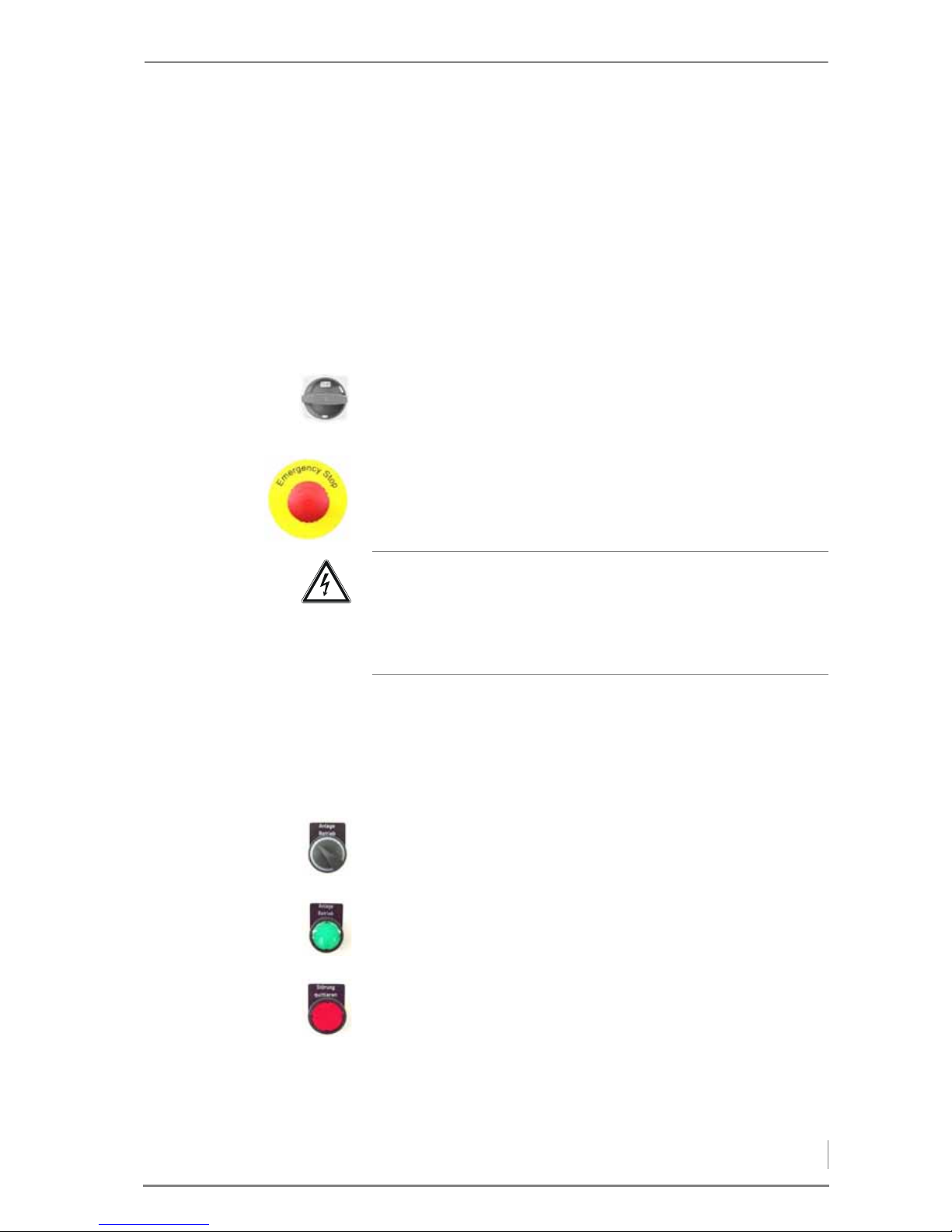
© HDG Bavaria GmbH 07/2008 HDG Compact 99 - 200 - Version 1 - en
6 Using the heating system – Overview of the controls and display components
69
6 Using the heating system
6.1 Overview of the controls and display components
MAIN SWITCH
The main switch is located on the side of the control cabinet. The
heating system can be shut down using the main switch.
EMERGENCY STOP
The emergency stop switch is located on the front plate of the control cabinet. If the emergency stop switch is pressed, all moving parts
of the heating system are switched off.
If the emergency stop switch is pulled out, the Acknowledge fault
button must first be pressed. Only then will all moving parts of the
heating system be switched back on and operational.
ADDITIONAL CONTROLS
Engage switch:
• switches the heating system on or off.
“System operation” indicator light
• lights up when the heating system is switched on.
Acknowledge fault key
• flashes when there is a fault.
• lights up when a fault is eliminated.
• must be pressed after rectifying a fault.
Danger!
Danger from electrical current or voltage!
The heating system is not rendered voltage-free by switching off
with the emergency stop switch. The heating system is only voltage-free if the main switch is turned off.
Page 70
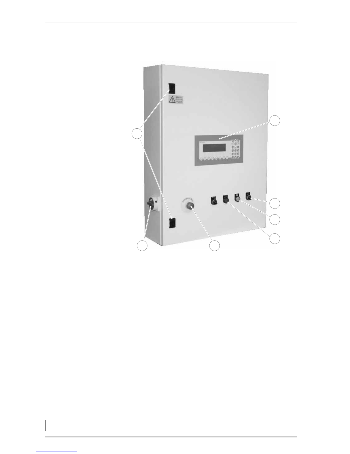
6 Using the heating system – Overview of the controls and display components
70
HDG Compact 99 - 200 - Version 1 - en © HDG Bavaria GmbH 07/2008
CONTROL CABINET MODEL EMD-C 215 EXCLUSIV
1 Lock mechanism of control cabinet
2Main switch
3Emergency stop
4 Acknowledge fault button with fault light
5 “System operation” indicator light
6Engage switch
7 HDG Control control unit
Figure 6/1 - Control cabinet model EMD-C 215 Exclusiv
1
32
7
6
4
5
Page 71
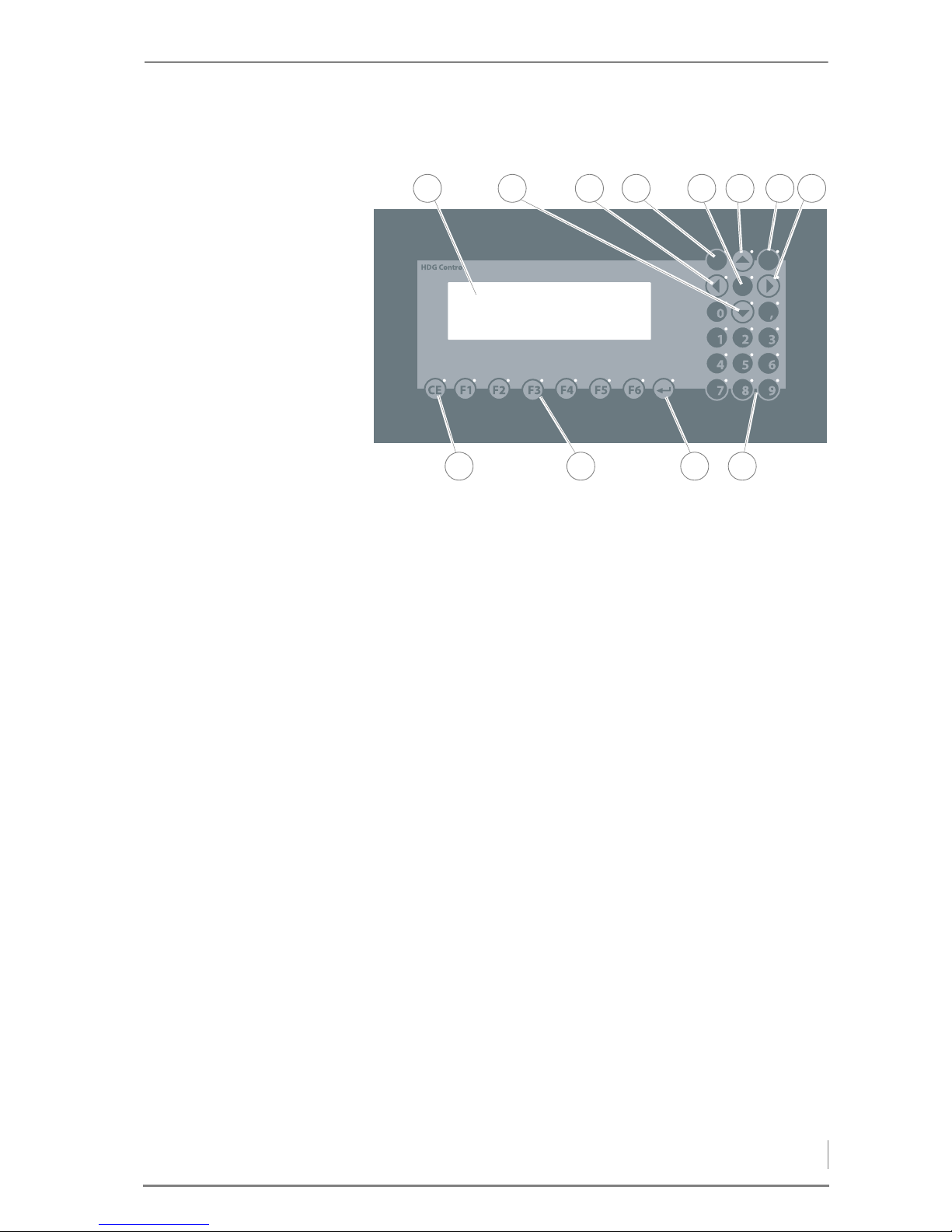
© HDG Bavaria GmbH 07/2008 HDG Compact 99 - 200 - Version 1 - en
6 Using the heating system – Overview of the controls and display components
71
HDG CONTROLUNIT
1Display
2 Down arrow button
3 No function assigned
4 Plus/minus sign change button
5 Program version info / Language selection button
6 Up arrow button
7 Configuration button
8 No function assigned
9 Numerical keypad
10 Enter or Input button
11 Function buttons (F1 to F6)
12 CE button
The control unit of the HDG Control is located in the front plate of the
control cabinet.
Through the control unit, you can adjust the HDG Control and obtain
information on current processes.
DISPLAY The display shows the selected information and parameters.
Figure 6/2 - HDG Control control unit
$POmH
.POJUPS
J
1 2 3 4 5 6 7 8
101112 9
Page 72
6 Using the heating system – Switching on the heating system
72
HDG Compact 99 - 200 - Version 1 - en © HDG Bavaria GmbH 07/2008
BUTTONS The heating system can be operated using the buttons.
The individual buttons have the following functions:
Arrow keys
• Switch between individual parameters in a display.
Plus/Minus button
• Changes the initial sign in front of numerical values.
Program version info key
• Displays the software version and enables changing the language.
Function (1 - 5) keys
• In the standard display, these buttons enable access to various
menus, e.g. the ON/OFF menu, as well as the triggering of functions which are shown in the bottom line of the display.
Function F6 key
• In the bottom line above the F6 button, END is always visible.
Press the F6 button to exit any submenu and return to the standard display.
Keys of the numerical keypad
• The keys of the numerical keypad are used to enter settings and
times.
Enter or Input key
• Confirms the changed value.
• One step forwards.
Configuration button
• If the HDG Control is traded, the configuration key is used to con-
firm adoption of the previous hours of operation.
6.2 Switching on the heating system
REQUIREMENTS Before the heating system is switched on, the following require-
ments must be met:
• The heating system has been commissioned by authorised specia-
lists.
• The fuses of the power supply are switched on.
• The main switch on the heating system is turned off.
• No operating mode is displayed on the control unit of the HDG
Control.
Not all keys are always activated on the keypad.
Depending on the menu, various buttons may be deactivated.
If a button is activated, a diode is lit in the upper right corner of the
button. Pressing the button will trigger the respective function.
Page 73
© HDG Bavaria GmbH 07/2008 HDG Compact 99 - 200 - Version 1 - en
6 Using the heating system – Switching off the heating system
73
• The fuel bunker is filled.
✎ See section “6.12 Filling the fuel bunker” in this chapter.
P
ROCEDURE 1. Turn the heating system main switch on.
✓ The control is activated.
✓ After a start-up phase, the display will first of all show a switch-on
message and then the standard display.
2. Set the engage switch to “1”.
✓ The display switches to Heating ON.
✓ The heating system is now switched on.
6.3 Switching off the heating system
The heating system can be switched off from any operating mode.
1. Set the engage switch to “0”.
✓ The heating system is switched off; the supplying of fuel is
stopped; the combustion air fan continues running for a preset
burn-out time.
2. Allow the heating system to burn out until the combustion air fan
switches off.
3. Turn the heating system main switch off.
✓ No operating mode is displayed on the control unit of the HDG
Control.
✓ The heating system has been de-energised.
6.4 Operating statuses
The heating system goes through the following states during operation:
Warning!
Frost danger!
Only switch off the heating system completely if you are certain
there is no danger of frost.
Operating status Description
Heating OFF • The main switch is turned on.
• The engage switch is at “0”.
Table 6/1 - Operating statuses
Page 74
6 Using the heating system – Operating statuses
74
HDG Compact 99 - 200 - Version 1 - en © HDG Bavaria GmbH 07/2008
1.Filling furnace • The current combustion chamber temperature is lower than the
preset ignition temperature.
• This operating status is maintained until the preset time for filling
the combustion chamber has been reached, the fill level indicator
signals or the combustion chamber temperature exceeds the ignition temperature.
Ignition • The preset ignition temperature has not been exceeded.
• The ignition fan is running and the combustion fan will start after
the preset delay.
• This operating status is maintained until the preset time for igni-
tion has been reached or the combustion chamber temperature
exceeds the ignition temperature.
Pre-ventilation • The fan is activated in order to remove the remaining gases from
the combustion chamber.
Heating-up phase • The feed quantity is increased by increments.
• This operating status is maintained until the preset time for hea-
ting up or the preset temperature in the combustion chamber
have been reached.
Automatic control • Only for “Combustion control” or “Combustion and output con-
trol” mode.
• The heating system runs automatically according to the configu-
red control mode.
Autom. uncontrolled • Operation of the heating system in “Fixed value” mode.
Burn-out phase • The preset boiler temperature has been reached.
• The boiler has been switched off.
• This operating status is maintained until the preset burn-out time
has elapsed.
Log wood emergency
operation
• Emergency operation of the heating system in “Log wood” mode.
• The combustion chamber must be filled through the inspection
door and ignited manually.
Temperature reached • The current boiler temperature is higher than the preset boiler
temperature.
• No demand on buffer.
• The boiler temperature is higher than the set temperature on the
regulating thermostat and the burn-out phase is complete.
Timer off • Operating status outside of the set enable time.
• The heating system is not in operation.
Emergency operation
active
• A sensor in the heating system is faulty.
• The boiler operates in accordance with the parameter values from
the submenu “Fixed value settings”.
Operating status Description
Table 6/1 - Operating statuses (continuation)
Page 75
© HDG Bavaria GmbH 07/2008 HDG Compact 99 - 200 - Version 1 - en
6 Using the heating system – Calling up information, selecting and modifying parameters
75
6.5 Calling up information, selecting and modifying parameters
On the display of the control panel for the HDG Control, you can call
up various information as well as select and modify parameters.
Due the freely programmable design and the numerous options in
heating system combinations, especially in regard to the extraction
technology, the number of parameters can vary greatly.
S
TANDARD DISPLAY The standard display shows you various information, such as opera-
ting status of the heating system, hours of operation, boiler temperature and the time.
Not enabled • The heating system is controlled via an external heating circuit
regulator.
• There was no enable command from the superordinate heating
circuit regulator.
Lambda stop • The residual oxygen value for combustion has fallen below the
minimum.
• The heating system waits until the minimum residual oxygen
value has been reached again.
Material stop • The fill level indicator in the combustion chamber has signalled.
• There is too much material in the combustion chamber.
• The heating system waits until the fill level indicator enables fil-
ling again.
Combustion chamber
temperature stop
• The maximum permitted temperature in the combustion cham-
ber has been exceeded.
• The heating system waits until the combustion chamber falls back
below the maximum permitted temperature.
Operating status Description
Table 6/1 - Operating statuses (continuation)
Heating OFF 0.0
hours
Boiler temp. : 40 °C 15:55
ON
OFF
°C
QUANT
ITY
TIME MAN. SERVICE INFO
Page 76
6 Using the heating system – Calling up information, selecting and modifying parameters
76
HDG Compact 99 - 200 - Version 1 - en © HDG Bavaria GmbH 07/2008
PROGRAM VERSION /
L
ANGUAGE SELECTION
1. Press the information key.
✓ The program version will appear in the display.
2. Press the F6 key to select the menu language
✓ The display switches to the submenu Language selection.
3. Press the F4 key under the FIELD command.
4. Press the F4 key under the CHOOSE command and select the
desired menu language.
5. Confirm the desired menu language with the Enter key.
✓ The desired menu language is set.
Program info
Basic program: COMP_12a / 15.12.11
Program file:
Program date: 15.12.11 Doebereiner
Program update:
Language selection
1-13
Language : 1 - German
FIELD CHOOSE END
By pressing the F6 key under the END command, you can exit the
Language selection menu window without changing the set-
ting.
The following pages show all practically available menu windows.
In actuality, only those menu windows are available to the operator
which are relevant for the heating system version.
Danger!
Material damage and injury due to incorrect settings!
Changing the following parameters requires comprehensive technical expertise. If the parameters are changed by untrained individuals, the heating system can be damaged and dangerous
operating conditions can arise.
Have ch ange s to the followi ng parameters made only by au thorised
specialists.
Page 77
© HDG Bavaria GmbH 07/2008 HDG Compact 99 - 200 - Version 1 - en
6 Using the heating system – ON/OFF menu
77
6.6 ON/OFF menu
PROCEDURE
1. Press the F1 key under the standard display screen.
✓ You are in the ON/OFF menu.
2. Scroll with the F1 or F2 key to the previous or next submenu.
3. Use the F3 key under the FIELD command in the respective sub-
menu to select the desired parameter.
4. Press the F4 key under the CHOOSE command and select the
desired setting.
5. Confirm each change with the Enter key.
✓ The desired parameter is set.
6. Press the F6 key under the END command to exit the submenu.
✓ The standard display is restored.
SETTING THE BASE LOAD / PEAK LOAD BOILER
This menu can be used to integrate an additional peak load boiler
using a third accumulator temperature sensor. With a double heating system, both boilers store energy in the accumulator. If the base
load boiler cannot charge the accumulator by itself, the peak load
boiler switches on for support.
This menu allows you to configure which heating system will be the
base load boiler and the which will be the peak load boiler in a
double heating system. A changeover is required after a certain
amount of operating hours so that both boilers will have approximately the same number of operating hours over several years.
✎ See “Procedure” in this section.
This is an optional submenu and only available with double heating
systems.
Changeover base load/peak load 1-01
Base load Peak load
Boiler-1 Boiler-2
After operating hours : 0 / 0 hr
FIELD CHOOSE END
Page 78
6 Using the heating system – ON/OFF menu
78
HDG Compact 99 - 200 - Version 1 - en © HDG Bavaria GmbH 07/2008
CONTROLLING BOILER-2 Boiler activation must be set to “External” on Boiler 2 with para-
meter 1-05 . Boiler 2 is controlled by a relay (K21) of Boiler 1. A normally-open contact of K21 is wired to the outgoing terminals 68/69/
70 on terminal strip X2. Boiler 2 likewise has terminals 68/69/70 on
terminal strip X2, which are internally wired to the PLC input “External demand”. In order to ensure this function works properly, it is
necessary to lay a connecting line (recommended: flexible control
cable of the type YSLY-JZ 3 x 1.0 mm ) between the two control cabinets.
F
UNCTION OF THE RETURN
PUMP
The return pump always runs if there is demand on the boilers and
the combustion chamber temperature exceeds 200 °C. This means
that Boiler 1 must receive demand signals from the accumulator
sensor and Boiler 2 must receive the external demand signal from
Boiler 1.
SETTING OPERATING TIMES
In this menu you can view and set the operating times of the heating
system. There are two switch-on and switch-off cycles available per
weekday.
B
OILER OPERATING TIMES ✎ See “Procedure” in this section.
1. In the Show switch on/off time 1-02 submenu, press the
F4 key under the EDITcommand in the bottom line of the display.
✓ The display switches to the Enter switch on/off time 1-
03 submenu.
✓ The day of the week and the first switch-on time are shown in
black.
2. Press the F4 key under the CHOOSE command in the display to se-
lect the day of the week that is to be reset.
3. Set the times using the numerical keypad.
Switch on/off times - Display 102
On: 00:00 On: 00:00 Time:15:55
Off: 24:00 Off: 00:00
: Day : Monday
EDIT END
Enter switch on/off time 1-03
On: 00:00 On: 00:00 Time:15:55
Off: 24:00 Off: 00:00
Day : Monday
CHOOSE END
Page 79
© HDG Bavaria GmbH 07/2008 HDG Compact 99 - 200 - Version 1 - en
6 Using the heating system – ON/OFF menu
79
4. Confirm each change with the Enter key.
✓ The cursor moves to the next digit pair.
5. Press the F4 key again under the CHOOSE command in the display
to select the next day of the week that is to be reset.
6. Press the F6 key under the END command to exit the Enter
switch on/off time 1-03 submenu.
✓ The operating times of the heating system are set.
✓ The display switches to Show switch on/off time 1-02.
7. Press the F6 key under the END command to exit the Display
switch on/off time 1-02 submenu.
✓ The standard display is restored.
P
ELLET HOPPER OPERATING
TIMES
1. Press the F1 key under the standard display screen.
✓ You are in the ON/OFF menu.
2. Scroll with the F2 key to the submenu Switch on/off time
- Hopper 1-04.
✓ The first switch-on time is shown in black.
3. Set the times using the numerical keypad.
4. Confirm each change with the Enter key.
✓ The cursor moves to the next digit pair.
5. Press the F6 key under the END command to exit the Switch
on/off time - Hopper 1-04 submenu.
✓ The standard display is restored.
If you want the heating system to be ready for operation 24 hours a
day, the first switch-on time must be set to ON: 00:00 and the
first switch-off time to OFF: 24:00!
This is an optional submenu and only available with pellet hoppers.
Switch on/off time - Hopper 1-04
On: 00:00 On: 00:00 Time:15:55
Off: 24:00 Off: 00:00
Day : Monday
EDIT END
Page 80
6 Using the heating system – ON/OFF menu
80
HDG Compact 99 - 200 - Version 1 - en © HDG Bavaria GmbH 07/2008
SETTING THE CONTROL, BOILER ACTIVATION, IGNITION AND LAMBDA
STOP
SETTING THE CONTROL MODES The heating system can be operated in different control modes.
These are:
• Fixed value
– In this version, the combustion is not optimised and there is no
output regulation. The combustion air supply and fuel quantity
is fixedly set and remains unchanged.
• Combustion control
– In this version the combustion is optimised. The primary and
secondary air supplies and the fuel quantity are adapted automatically within a specified range of combustion. There is no
output regulation. (Standard setting for use of accumulator).
• Control of combustion and output
– In addition to the combustion control, this version also regu-
lates the output of the heating system for the demand.
• Oil burner
– In this version, an oil burner must be installed in the boiler. This
control mode switches off all units except the return pump and
return mixing valve. If the regulating thermostat on the boiler
has enabled this, the oil burner and the return mixing valve regulate according to the set return temperature. If not enabled,
the return mixing valve closes and only opens briefly in the
case of a higher temperature.
• Log wood
– This mode is suitable only for emergency operation. The com-
bustion air fans are switched on or off according to the boiler
temperature.
✎ See “Procedure” in this section.
Setting 1-05
Control : Fixed value
Activate boiler : Accumulator temperature sensor
Ignition : On
Lambda stop : On
FIELD CHOOSE END
The standard setting for systems with accumulators is Combustion control.
Page 81

© HDG Bavaria GmbH 07/2008 HDG Compact 99 - 200 - Version 1 - en
6 Using the heating system – ON/OFF menu
81
SELECTING AND SETTING BOILER
ACTIVATION
In boiler activation mode, there are various ways of switching the
heating system on and off.
• Accumulator temperature sensor
– In this version, the heating system is switched on and off
through two accumulator temperature sensors. After falling
below the preset temperature at the “Acc. top” sensor, the
boiler is started. After exceeding the preset temperature at the
“Acc. bottom” sensor, the boiler is switched off.
✎ See section “6.7 °C/QUANTITY menu” in this chapter.
• Accumulator and external
– In this version, the heating system is switched on and off if the
accumulator temperature sensor has enabled this and there is
a simultaneous external demand.
• Accumulator or external
– In this version, the heating system is switched on and off if the
accumulator temperature sensor has enabled this or there is a
simultaneous external demand.
• On
– In this version, the heating system is switched on and off
through the boiler supply temperature sensor. The accumulator temperature sensors are ignored.
• Thermostat
– In this version, the heating system is switched off through the
boiler supply temperature sensor and switched on through the
accumulator thermostat.
• External
– In this version, the heating system is switched on and off
through an external controller. Observe the terminal connection points on the circuit diagram in the control cabinet.
✎ See “Procedure” in this section.
A
CTIVATING OR DEACTIVATING
AUTOMATIC IGNITION
The automatic ignition function can be switched off, thus activating
the function for sustaining the embers.
✎ See “Procedure” in this section.
The standard setting for systems with accumulators is Acc.
temp. sensor.
The standard setting is On.
Sustaining the embers is only performed in emergency operation!
Page 82
6 Using the heating system – ON/OFF menu
82
HDG Compact 99 - 200 - Version 1 - en © HDG Bavaria GmbH 07/2008
ACTIVATING THE FUNCTION
“L
AMBDA STOP”
If the specified minimum residual oxygen value is not met, the fuel
feeding is interrupted until the residual oxygen values are again
within the acceptable range.
✎ See “Procedure” in this section.
✎ For the setting of the minimum lambda value, see section “6.7 °C/
QUANTITY menu”, paragraph “Entering the residual oxygen setting”.
ADJUSTING THE ASH REMOVAL SETTING
The movement of the stepping grate and the ash removal system
can be switched off.
✎ See “Procedure” in this section.
CHANGING THE CLEANING SYSTEM SETTING
The automatic heat exchanger cleaning system can be switched off.
✎ See “Procedure” in this section.
Setting 1-06
Ash removal : Automatic
CHOOSE END
The standard setting is Automatic.
Setting 1-07
Cleaning system : On
CHOOSE END
The standard setting is On.
Page 83
© HDG Bavaria GmbH 07/2008 HDG Compact 99 - 200 - Version 1 - en
6 Using the heating system – ON/OFF menu
83
MODIFYING THE DUST REMOVAL SETTING
The fan for the HDG cyclone dust extractor, if available, can be set to
four different operating modes.
• 0-Off
– In this mode, the fan for the de-dusting function is not
available or not in operation.
• 1-Continuous
– In this mode, the fan is continuously in operation, e.g. for
cleaning work.
• 2-Heating up
– In this mode, the fan for the de-dusting function is only in ope-
ration during the heating up phase. After the heating up phase,
it switches off.
• 3-Automatic
– Depending on the local site conditions and fuel characteristics,
this mode may be required as a flue support to stabilise operation. The fan starts and continues running through the operating mode Automatic. Afterwards it switches off.
• 4-During combustion
– In this mode, the fan is in operation if the combustion fan of the
heating system is running.
In addition, in this menu it can be set if an underpressure control was
activated.
✎ See “Procedure” in this section.
Setting 1-08
Dust removal : 4-During combustion
Underpressure control On
FIELD CHOOSE END
Standard setting for dust removal is 4-with combustion.
The mechanical setting options on the fan itself should also be
noted.
Page 84
6 Using the heating system – ON/OFF menu
84
HDG Compact 99 - 200 - Version 1 - en © HDG Bavaria GmbH 07/2008
MODIFYING THE EXTRACTION SETTING
The heating system can, for example, include a separate delivery
system for a shaving silo. In addition, the flexi blade delivery system
can be employed for extraction in combination with an additional
conveyor auger. Extraction can be controlled in various ways.
• Cycles
– In this version, the extraction runs in a cycle with configurable
pause intervals and runtimes.
✎ For setting options, see the section “6.8 TIME menu” in this
chapter.
• Continuous running
– In this version, the extraction runs continuously upon demand.
✎ See “Procedure” in this section.
MODIFYING THE PELLET VACUUM DELIVERY SYSTEM SETTING
Optionally, the heating system can also be operated with a pellet vacuum delivery system.
• 1 Suction point
– In this variant, the pellet vacuum delivery system is operated
without hose junction.
• 2/3 Suction points
– In this variant, the pellet vacuum delivery system is operated
with hose junction with 2 or 3 suction points.
✎ See “Procedure” in this section.
Setting 1-09
Delivery system : Cycles
CHOOSE END
The standard setting is Cycles.
Setting Pellet vacuum delivery
system 1-10
Vacuum delivery system : 1 Suction point
Operating mode : Automatic
FIELD END
Page 85
© HDG Bavaria GmbH 07/2008 HDG Compact 99 - 200 - Version 1 - en
6 Using the heating system – ON/OFF menu
85
MODIFYING THE MOVING FLOOR SETTING
A moving floor delivery system can be an optional component of a
heating system. The individual scraper blades of the moving floor
can be separately controlled.
• Off
– In this version, all scraper blades are switched off.
• Auto scraper 1
– In this version, only scraper 1 of the moving floor is controlled.
• Auto scraper 2
– In this version, only scraper 2 of the moving floor is controlled.
• Auto scraper 1 + 2
– In this version, both scraper blades of the moving floor are al-
ternately controlled.
• Manual mode
– In this version, the moving floor scrapers can be controlled by
hand. The manual control function in the Manual menu is
enabled.
✎ See “Procedure” in this section.
The standard setting is 1 Suction point.
Setting 1-11
Moving floor : Manual mode
FIELD END
Page 86
6 Using the heating system – °C/QUANTITY menu
86
HDG Compact 99 - 200 - Version 1 - en © HDG Bavaria GmbH 07/2008
6.7 °C/QUANTITY menu
In this menu, you can view and set temperatures, combustion air
quantity, fuel type/quantity and control parameters. All target values
can be modified. The actual values displayed indicate the current
status.
PROCEDURE
1. Press the F2 key under the standard display screen.
✓ You are in the °C/Quantity menu.
2. Scroll with the F1 or F2 key to the previous or next submenu.
✓ The first resettable parameter is shown in black.
3. Enter the desired value using the numerical keypad.
4. Confirm each change with the Enter key.
✓ The desired parameter is set.
5. Scroll with the Up or Down key to the previous or next submenu.
✓ The next resettable parameter is shown in black.
6. Repeat steps 3 to 5 for additional parameters.
7. Press the F6 key under the END command to exit the submenu.
✓ The standard display is restored.
VIEWING FLUE GAS TEMPERATURE
✎ See “Procedure” in this section.
This is an optional submenu and only available when operating the
boiler with flue gas temperature sensor.
°C /
Quantity 2-01
Flue gas temperature
:99°C
END
Page 87
© HDG Bavaria GmbH 07/2008 HDG Compact 99 - 200 - Version 1 - en
6 Using the heating system – °C/QUANTITY menu
87
SETTING THE BOILER SUPPLY AND RETURN TEMPERATURE
✎ See “Procedure” in this section.
READING VALUES FROM THE CONTROLLER
You can read off the relevant values in the display.
✎ See “Procedure” in this section.
FIXED VALUE - SETTING THE MATERIAL AND AIR QUANTITY
✎ See “Procedure” in this section.
°C /
Quantity 2-02
Boiler temp. : 80 / 60 °C
Return temp. : 60 / 50 °C
Comb. chamber temp. : 600 / 331 °C
Residual oxygen : 8.0 /8.6 %
END
The Boiler temperature target value must not fall below 70°C
and must not exceed 85°C. The Return temperature target
value must not fall below 60°C. Comb. chamber temp. and Re-
sidual oxygen cannot be changed!
Values from controller
2-03
Material quantity : 50.0 /.40.0 %
Material difference : .0 /50.0 %
Primary air : 25 / 1 %
Secondary air : 20 / 1 %
END
Fixed value settings 2-04
Material quantity : 40.0 /.40.0 %
Primary air : 15 / 1 %
Secondary air : 80 / 1 %
Comb. chamber temp. : 600 / 331 °C
END
Page 88
6 Using the heating system – °C/QUANTITY menu
88
HDG Compact 99 - 200 - Version 1 - en © HDG Bavaria GmbH 07/2008
SELECTING A MATERIAL TYPE
In this menu you can choose from four different heating material settings. The varying quality of the heating material can also be taken
into account. All parameters can be newly defined and reset for each
type of material.
✎ See “Procedure” in this section.
DEFINING THE SWITCH ON/OFF TIMES FOR THE BOILER
This menu is used to define the switch on/off times of the boiler
based on the temperature sensor of the accumulator. The switching
on and off of the boiler can be changed by adapting the temperature.
• Temp. acc. top below
– If this temperature set for the top accumulator sensor is not
met, the boiler switches back on.
• Temp. acc. bottom above
– If the temperature set for the bottom accumulator sensor is ex-
ceeded, the boiler switches off.
In this menu, the settings of the fuel and air quantities are fixed
value presets for “Fixed value” operation only.
✎ See section “6.6 ON/OFF menu”, under “Setting the control,
boiler activation, ignition and Lambda Stop”.
Material type 205
Material 1 : ( Material_1 )
END
The standard setting for start-up is usually Material: 1.
Independent modification of settings for adapting to the fuel
should be made under another fuel type so as not to change the
startup settings. For example, save the start-up setting under Ma-
terial: 2 and only then modify this setting.
Page 89
© HDG Bavaria GmbH 07/2008 HDG Compact 99 - 200 - Version 1 - en
6 Using the heating system – °C/QUANTITY menu
89
✎ See “Procedure” in this section.
INTEGRATING THE PEAK LOAD BOILER
This menu can be used to integrate an additional peak load boiler
using a third accumulator temperature sensor. The switch-on and
switch-off temperatures of the accumulator for the peak load boiler
are set here.
• Temp. acc. top below
– If this temperature set for the upper accumulator sensor is not
met, the peak load boiler switches on.
• Temp. acc. middle above
– If this temperature set for the middle accumulator sensor is ex-
ceeded, the peak load boiler switches off.
✎ See “Procedure” in this section.
Temperature adjustment using the accumulator sensors is only
available if the boiler activation is set to “Accumulator temperature
sensor”.
✎ See section “6.6 ON/OFF menu”, under “Selecting and setting
boiler activation”.
Boiler on/off 2-06
On: Temp. acc. top below 70 / 58°C
Off: Temp. acc. bottom above 65 / 51°C
END
The standard setting for the boiler switch-on temperature for
Temp. acc. top below is 70 °C.
The standard setting for the boiler switch-off temperature for
Temp. acc. bottom above is 65 ?.
This is an optional submenu and only available with double heating
systems (if necessary, also with oil/gas boilers).
Peak load boiler 2-07
On: Temp. acc. top below 55 / 68°C
Off: Temp. acc. middle above 65 / 65°C
END
Page 90
6 Using the heating system – °C/QUANTITY menu
90
HDG Compact 99 - 200 - Version 1 - en © HDG Bavaria GmbH 07/2008
PEAK LOAD BOILER MONITORING
This menu can be used to integrate an additional peak load boiler
using a third accumulator temperature sensor.
The ACT temperature on the accumulator middle sensor must be
below the SET temperature
If the set value for the temperature increase is not reached within the
specified delay time, the peak load boiler is automatically activated.
✎ See “Procedure” in this section.
ENTERING THE COMBUSTION CHAMBER TEMPERATURE SETTING
This menu is used to set the furnace temperature range for operation
with combustion and output control.
• MAX
– The boiler attempts to reach this maximum temperature at full
load.
• MIN
– This minimum temperature is the lower limit for partial-load
operation of the boiler.
✎ See “Procedure” in this section.
This is an optional submenu and only available with double heating
systems (if necessary, also with oil/gas boilers).
Peak load boiler 2-08
Monitoring of accumulator temp. at top
Temp. rise less than 5 / 68°C
Delay time 30 / 0 m
END
The combustion chamber temperature settings apply for Combustion control as well as Combustion and output control.
✎ See section “6.6 ON/OFF menu”, under “Setting the control,
boiler activation, ignition and Lambda Stop”.
Comb. chamber temp. PID-1 6-01
MAX: 600°C T_SET: 80°C KP: 5.00
MIN: 400°C T_ACT: 0°C TN: 900.00
TV: 10.00
SET: 600°C
END
Page 91
© HDG Bavaria GmbH 07/2008 HDG Compact 99 - 200 - Version 1 - en
6 Using the heating system – °C/QUANTITY menu
91
ENTERING MATERIAL AND TEMPERATURE SETTINGS
In this menu, you can define the fuel quantity for controlled operation of the boiler. The furnace temperature setting is also set for the
control type “Combustion control”.
✎ See “Procedure” in this section.
ENTERING THE PRIMARY AIR SETTING
In this menu, you can set the primary air quantity for controlled operation of the boiler.
✎ See “Procedure” in this section.
The standard setting is MAX 600°C and MIN 400°C.
The material settings apply for Combustion control as well as
Combustion and output control.
✎ See section “6.6 ON/OFF menu”, under “Setting the control,
boiler activation, ignition and Lambda Stop”.
Material quantity PID-2 6-02
MAX: 28.0% CCT_SET: 600°C KP: 5.00
MIN: 15.0% CCT_ACT: 50°C TN: 100.00
TV: 0.00
SET: 15.0% Factor : 50% KP_ 17.90
END
The difference between fuel quantity MAX and MIN should be specified as a range (approx. 25%) adapting to the required value.
The primary air settings apply for Combustion control as well
as Combustion and output control.
✎ See section “6.6 ON/OFF menu”, under “Setting the control,
boiler activation, ignition and Lambda Stop”.
Primary air R-1 6-03
Air_Max : 30% Fue_Set: 15.0%
Air_Min : 25% Set_Air: 25.0%
END
Page 92
6 Using the heating system – °C/QUANTITY menu
92
HDG Compact 99 - 200 - Version 1 - en © HDG Bavaria GmbH 07/2008
ENTERING THE RESIDUAL OXYGEN SETTING
This menu is used to enter the residual oxygen setting for controlled
operation of the boiler.
✎ See “Procedure” in this section.
ENTERING THE SECONDARY AIR SETTING
In this menu, you can set the secondary air quantity for controlled
operation of the boiler. The O2 minimum value for the Lambda Stop
function can also be defined.
✎ See “Procedure” in this section.
The difference between primary air quantity Air_Max and
Air_Min should be specified as a range adapting to the required
value (approx. 25 %).
The residual oxygen setting applies for Combustion control as
well as Combustion and output control.
✎ See section “6.6 ON/OFF menu”, under “Setting the control,
boiler activation, ignition and Lambda Stop”.
O2 preset value R-2 6-04
O2_MAX: 8.0 % CCT_SET: 600°C
O2_MIN: 8.0 % CCT_ACT: 50°C
O2_SET: 8.0 %
O2_ACT: 12.8
END
The standard setting for O2_Max and O2_Min is 8.0%.
The secondary air setting applies for Combustion control as
well as Combustion and output control.
✎ See section “6.6 ON/OFF menu”, under “Setting the control,
boiler activation, ignition and Lambda Stop”.
Page 93
© HDG Bavaria GmbH 07/2008 HDG Compact 99 - 200 - Version 1 - en
6 Using the heating system – °C/QUANTITY menu
93
ADAPTING THE MATERIAL QUANTITY/O2
This menu allows fuel to be increased or adapted within a range defined by the Delta Min/Max values.
✎ See “Procedure” in this section.
Secondary air O2 PID-3 6-05
Max: 100% SET: 8.0% KP: 200.0
Min: 20% ACT: 12.8% TN: 200.0
ACT: 100% MIN: 5.0% TV: 0.0
END
The standard setting for the secondary air is 100% for Max and 20%
for Min.
If this O2 minimum value is not met, the Lambda Stop function is
triggered.
✎ See section “6.6 ON/OFF menu”, under “Activating the function
“Lambda Stop””.
The material quantity/O2 settings apply for Combustion con-
trol as well as Combustion and output control.
✎ See section “6.6 ON/OFF menu”, under “Setting the control,
boiler activation, ignition and Lambda Stop”.
Fuel quantity modification by O2 R-3 6-06
Delta_FUE_MIN: -10% FUE_SET: 15.0%
Delta_FUE_MAX: 10% FUE_ACT: 15.0%
Delta_FUE_ACT: 0%
Delay : 10s
END
The standard setting for Delta FUE_MIN is -10 % and 10 % for
Delta FUE_MAX.
Page 94
6 Using the heating system – TIME menu
94
HDG Compact 99 - 200 - Version 1 - en © HDG Bavaria GmbH 07/2008
SETTING UNDERPRESSURE CONTROL VALUES
In this menu, the settings for fan speed with the HDG cyclone dust
extractor and the underpressure value for the underpressure control
can be defined.
✎ See “Procedure” in this section.
6.8 TIME menu
In this menu you can view and set all time parameters relating to ignition, de-ashing, cleaning and delivery systems. All target values can
be modified. The actual values displayed indicate the current status.
PROCEDURE
1. Press the F3 key under the standard display screen.
✓ You are in the Time menu.
2. Scroll with the F1 or F2 key to the previous or next submenu.
✓ The first resettable parameter is shown in black.
3. Enter the desired value using the numerical keypad.
4. Confirm each change with the Enter key.
✓ The desired parameter is set.
5. Scroll with the Up or Down key to the next submenu.
✓ The next resettable parameter is shown in black.
6. Repeat steps 3 to 5 for additional parameters.
7. Press the F6 key under the END command to exit the submenu.
✓ The standard display is restored.
PID pressure control fan 6-07
MAX : 100% P_Min : -10pa KP: 20
MIN : 20% P_Max : -50pa TN: 40
ACT : 90% P_Set: -20pa TV: 0
Fact.: 73% P_Ist : -25pa KP_: 30.0
END
The standard setting is 100% for MAX and 20% for MIN.
Page 95
© HDG Bavaria GmbH 07/2008 HDG Compact 99 - 200 - Version 1 - en
6 Using the heating system – TIME menu
95
SETTING THE FILLING, IGNITION AND FAN ACTIVATION
This submenu is used to set the time for the initial filling with fuel and
the running time of the ignition fan. You can also set the time after
which the combustion fan is added during the igniting phase.
✎ See “Procedure” in this section.
SETTING PRE-AIR, HEATING UP AND BURNING OUT
This submenu enables you to set the pre-ventilation time for fanning
the fuel without material feeding, the heating up time during which
the fuel quantity is heated to the target value, and the burn-out time
during which material feeding is stopped and the combustion fan
switches off after a specified time.
✎ See “Procedure” in this section.
SETTING THE ASH REMOVAL AND EMBER SUSTAINING FUNCTIONS
This submenu is used to set the time for the grate motion and thus
the de-ashing interval. In addition, the time interval for the material
feeding can be influenced if the Ignition parameter is set to Off.
✎ See “Procedure” in this section.
Time 3-01
1st filling : 6.0 / 0.0 m
Ignition : 6.0 / 0.0 m
Fan activation : 3.0 / 0.0 m
END
When changing the fuel, the parameters 1st filling and Ignition must be regulated to avoid malfunctions during ignition.
Time 3-02
Pre-ventilation : 30 / 0 s
Heating up : 7.0 / 0.0 m
Burning out : 30.0 / 0.0 m
END
The Keep glow setting is only used as an “emergency” function
should the ignition fan fail!
Page 96
6 Using the heating system – TIME menu
96
HDG Compact 99 - 200 - Version 1 - en © HDG Bavaria GmbH 07/2008
SETTING THE CLEANING FUNCTION
In this submenu you can set the time for the movements of the
cleaning system as well as scanning of the limit switch.
✎ See “Procedure” in this section.
SETTING FILLING DELAY OF DOSAGE TANK
In this submenu you can set a time-delayed switching on for the silo
delivery system. If the fill level indicator in the dosage tank signals
that more fuel is required, the extraction switches back on after the
specified time has elapsed.
Time 3-03
Ash removal runtime : 12 / 0 s
Ash removal pause time : 70.0 / 0.0 m
Keep glow runtime : 10 / 0 s
Keep glow pause time : 10.0 / 0.0 m
END
When changing the heating material, the burn-out behaviour must
be checked on the grate of the boiler. If necessary, adjust the Ash
removal pause parameter. In general, only this parameter
should be changed and the Ash removal feed parameter only
changed in exceptional instances.
Time 3-04
Cleaning system pause time : 24.0 / 0.0 h
Cleaning system runtime : 140 / 0 m
Cleaning system monitoring : 40 / 0 s
END
When changing the heating material, the burn-out behaviour of the
boiler must be checked in the area of the heat exchanger surfaces.
If necessary, adjust the Cleaning pause time parameter. In
general, only this parameter should be changed and the
Cleaning system runtime parameter only changed in exceptional instances.
This parameter is an optional submenu and only available for heating systems with metering tank and fill level indicator.
Page 97
© HDG Bavaria GmbH 07/2008 HDG Compact 99 - 200 - Version 1 - en
6 Using the heating system – TIME menu
97
✎ See “Procedure” in this section.
SETTING FILLING DELAY OF DOSAGE TRANSITION
In this submenu you can set a time-delayed switching on for the silo
delivery system. If the fill level indicator in the dosage transition signals that more fuel is required, the extraction switches back on after
the specified time has elapsed.
✎ See “Procedure” in this section.
SETTING THE MOVING FLOOR DELIVERY SYSTEM
In this submenu you can enter settings for a moving floor delivery
system.
✎ See “Procedure” in this section.
Time 3-05
Delay filling
Dosage tank TFD 160 : 3.0 / 0.0 m
END
This is an optional submenu and only available for heating systems
with dosage transition and fill level indicator.
Time 3-06
Delay filling
Dosage transition : 3.0 / 0.0 s
END
This parameter is an optional submenu and only available with moving floor delivery systems.
Moving floor 3-07
Moving floor runtime : 10.0 / 0.0 s
Moving floor pause time : 10.0 / 0.0 s
Moving floor delay time : 10.0 / 0.0 s
Moving floor lead time : 0.0 / 0.0 s
END
Page 98
6 Using the heating system – TIME menu
98
HDG Compact 99 - 200 - Version 1 - en © HDG Bavaria GmbH 07/2008
SETTING THE AGITATOR
In this submenu you can enter the settings for the lag time of the agitator in connection with a moving floor delivery system.
✎ See “Procedure” in this section.
SETTING THE PEAK LOAD BOILER
In this submenu you can set the times for the peak load boiler.
✎ See “Procedure” in this section.
SETTING THE CYCLES OF THE PELLET AUGER
In this submenu you can set the time interval for a timed cycle of the
pellet auger.
✎ See “Procedure” in this section.
This is an optional submenu and only available with moving floor
delivery systems and double heating systems.
Agitator 3-08
Agitator lag time : 2.0 / 0.0 s
END
This is an optional submenu and only available with peak load boilers.
Time 3-09
Peak-load boiler
Delay time 10 / 0 m
Minimum runtime : 20 / 0 m
END
This is an optional submenu.
This setting is only available when the delivery system is set to “Cycles”.
✎ See section “6.6 ON/OFF menu”, under “Modifying the extraction
setting”.
Page 99
© HDG Bavaria GmbH 07/2008 HDG Compact 99 - 200 - Version 1 - en
6 Using the heating system – TIME menu
99
SETTING THE HOPPER EXTRACTION SYSTEM
In this submenu you can enter settings for a hopper extraction
system, such as the lead times and lag times.
✎ See “Procedure” in this section.
HOPPER EXTRACTION SYSTEM - SETTING ADDITIONAL PARAMETERS
In this submenu you can enter additional settings for a hopper extraction system.
✎ See “Procedure” in this section.
Time 3-10
Delivery system runtime : 2.0 / 0.0 s
Delivery system pause time : 4.0 / 0.0 s
END
This is an optional submenu and only available with hopper extraction systems.
Pellet hopper 3-11
Vacuum fan lead time : 10 / 0 s
Vacuum fan lag time : 10 / 10 s
Delay fill level indicator : 60 / 60 s
Start filling hopper in : 30 / 1.0 m
END
This is an optional submenu and only available with hopper extraction systems.
Pellet hopper 3-12
Max. vacuum fan runtime : 25 / 0 m
Max. vacuum fan pause time : 25 / 0 m
Number of fill attempts : 3 / 0 x
END
Page 100
6 Using the heating system – TIME menu
100
HDG Compact 99 - 200 - Version 1 - en © HDG Bavaria GmbH 07/2008
CENTRAL ASH REMOVAL SYSTEM - SETTING LAG TIME
This submenu is used to set the lag time for the central ash removal
system.
✎ See “Procedure” in this section.
SERVICE MESSAGES - SETTING REMINDER TIME
This submenu can be used to set various times at which service messages should appear.
• WA Empty ash box
– When the set runtime of the ash removal auger is exceeded,
the warning "Please empty ash box" appears. The heating
system d oes not shut off at the ap pearance of this warnin g. The
"0" setting deactivates this function.
• ST Empty ash box
– When the set runtime of the ash removal auger is exceeded,
the fault message "Ash box full" appears. The heating system
shuts off at this fault. The "0" setting deactivates this function.
• WA Lubricate screw stoker
– When the set runtime of the screw stoker is exceeded, the war-
ning "Please lubricate screw stoker" appears. The heating
system d oes not shut off at the ap pearance of this warnin g. The
"0" setting deactivates this function.
• WA Lubricate cleaning system
– When the set runtime of the cleaning system is exceeded, the
warning "Please lubricate cleaning system" appears. The heating system does not shut off at the appearance of this warning. The "0" setting deactivates this function.
✎ See “Procedure” in this section.
This is an optional submenu and only available with central ash removal systems.
Time 3-13
Ash conveyor lag time : 120 / 0 s
END
 Loading...