

Page 1
®
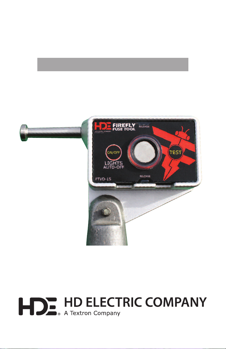
FIREFLY
FUSE TOOL & VOLTAGE DETECTOR
a n d T E S TER
Operating Instruction Manual
Making the Invisible Visible
14 75 Lak esi de Drive • Wa uke gan , I llinois 60 085 U. S.A . • 847.473.4980
f ax 8 4 7 . 4 7 3 . 49 81 • we bs it e: w ww . HD El ec tr ic Co mp an y .c o m
TM
Page 2

®
FIREFLY
FUSE TOOL & VOLTAGE DETECTOR
a n d T E S TER
Operating Instruction Manual
IMPORTANT SAFETY INFORMATION . . . . . . . . . . . . . . . . . . . . . . . . . . . . . . . . . . . . . . . . . . . . . . . . . . . . . . .3
DESCRIPTION . . . . . . . . . . . . . . . . . . . . . . . . . . . . . . . . . . . . . . . . . . . . . . . . . . . . . . . . . . . . . . . . . . . . . . . . . . . . . .4
VOLTAGE DETECTOR SELF-TEST OPERATION . . . . . . . . . . . . . . . . . . . . . . . . . . . . . . . . . . . . . . . . . . . . . . .5
INSTRUCTIONS FOR USE . . . . . . . . . . . . . . . . . . . . . . . . . . . . . . . . . . . . . . . . . . . . . . . . . . . . . . . . . . . . . . . . . . .6
OPERATION . . . . . . . . . . . . . . . . . . . . . . . . . . . . . . . . . . . . . . . . . . . . . . . . . . . . . . . . . . . . . . . . . . . . . . . . . . . . . . . .7
BATTERY REPLACEMENT . . . . . . . . . . . . . . . . . . . . . . . . . . . . . . . . . . . . . . . . . . . . . . . . . . . . . . . . . . . . . . . . . . .8
MAINTENANCE AND CARE . . . . . . . . . . . . . . . . . . . . . . . . . . . . . . . . . . . . . . . . . . . . . . . . . . . . . . . . . . . . . . . .9
TECHNICAL SPECIFICATIONS . . . . . . . . . . . . . . . . . . . . . . . . . . . . . . . . . . . . . . . . . . . . . . . . . . . . . . . . . . . . . .9
OPTIONAL ACCESSORIES . . . . . . . . . . . . . . . . . . . . . . . . . . . . . . . . . . . . . . . . . . . . . . . . . . . . . . . . . . . . . . . . .10
WARRANTY AND LIABILITY . . . . . . . . . . . . . . . . . . . . . . . . . . . . . . . . . . . . . . . . . . . . . . . . . . . . . . . . . . . . . . .12
14 75 Lakeside Dr ive • Waukegan, I llinois 60085 U.S .A. • 847.473.498 0
f ax 8 4 7. 47 3. 4 9 8 1 • w eb si te : w ww . HD El ec tr ic Co m p a ny. co m
2
Page 3

IMPORTANT SAFETY INFORMATION
READ AND UNDERSTAND ALL ELEMENTS OF THIS MANUAL PRIOR TO USE.
WARNING: Use of the FireFly Fuse Tool Voltage Detector in certain corner locations
may result in incorrect indications. Those conditions should be avoided or re-tested
in a nearby location. Voltage cancellation effects inside right angles (conductors
approximately 90° apart) may cause false indications if the Detector is used within
3 feet (1 meter) of the conductors joining. Other operating limitations may exist.
These are found in the Instructions for Use section of this manual (page 6).
DANGER: Never insert the FireFly Detector into metal enclosures, switchgear, through
access holes or use in any situations other than overhead conductors. Incorrect
use of the FireFly Detector can lead to severe injury or death.
SAFETY
Rigorous hotstick work practices should be used at all times. All industry, OSHA and
company work practices and safety procedures shall apply when working on or near
high voltage systems. When used properly, the FireFly Detector reliably provides an
alarm warning of energized conductors.
• Only trained, professional operating personnel should use this equipment. The
voltages these instruments operate at are to be considered live and dangerous
and are lethal. Severe injury or death can occur if improperly used.
• Make certain all other safety considerations have been identified, implemented
and are in place prior to using this equipment. Maintain proper work clearances
at all times.
• Make certain the FireFly Detector is properly rated for use on the system voltages
you will test.
• Prior to using, make certain to inspect the instrument for any physical damage,
cleanliness and check for proper working order using the test button. Remove
from service and do not use if you suspect a problem with any of the above.
• Test the instrument before and after each use by testing on a known voltage source
such as the PT-FTVD Proof Tester® Detector Tester for FireFly Voltage Detectors.
• Never allow another high voltage conductor, or grounded point, to come in
contact with the tool during use. Keep housing of FireFly Detector free and
clear of all structures at all times.
• Hotsticks must be used at all times per industry, OSHA and company work practices.
• Never touch the detector or control panel during contact with high voltage. The FireFly
Detector should be considered to be at the same voltage as the conductor under test.
3
Page 4

DESCRIPTION
The FireFly Detector combines a lighted fuse tool with voltage detection adding
an extra margin of safety for those working on distribution lines. Operating
frequency is 60Hz (optional 50Hz available).
The FireFly Detector includes is a single range voltage detector. One range of
operating voltages is set within the unit. A typical range is 4kV-12kV. If the unit
contacts a conductor energized from 4kV (line-to-line) to 12kV (line-to-line),
red LEDs flash and an audible alarm is activated.
Other FireFly Detector voltage ranges are available up to and including 35kV.
Do not use the detector at voltages higher or lower than it is rated. Consult
the product label for the specific range or levels for the unit supplied.
When operating within the unit’s voltage range (see product label), the FireFly
Detector will provide both an audible and visual alarm upon making contact
with an energized conductor. The FireFly Detector units will not give an alarm
due to induced voltage on de-energized conductors, unless the induced voltage
level exceeds the threshold voltage of the detector.
The FireFly Detector should be tested both prior to and after line testing to make
certain the unit is working properly. The FireFly Voltage Detector has a built-in
self-test feature to make certain the unit is working properly. Push the TEST button,
which will test the battery, the electronic circuitry and the audible and visual alarm
(see page 5 for more information). To test the FireFly Detector on a known voltage
source before and after each use, the PT-FTVD Proof Tester FireFly Voltage Detector
Tester can be used (see page 10 for more information).
If the FireFly Detector does not pass the self-test, the voltage detector batteries
should be replaced and the unit re-tested. If the unit still does not pass the test,
the unit should be sent in for repair. NEVER USE THE FIREFLY DETECTOR IF THE
SELF-TEST IS NOT SUCCESSFULLY PASSED! See Self-Test Operation Section (page 5).
Four (4) 3V lithium batteries power the FireFly Voltage Detector and white lights.
Even though the voltage detector is always “ON” and sensing voltage, the voltage
sensor batteries should last for approximately one year under normal use. We do
recommend however, replacing the batteries every six months. If the instrument
is to be stored for a year or more, remove the battery during storage.
A universal spline adapter is built into the aluminum housing of the FireFly Detector
units. Extension hotsticks are required for use at all times. Hotsticks are available from
HD Electric Company and must be used when placing the FireFly Detector in contact
with any conductor.
4
Page 5
VOLTAGE DETECTOR SELF-TEST OPERATION
The self-test feature provides a full test of the battery, the voltage detection circuitry
and the audible and visual alarm.
NOTE: The self-test should be used both prior to and after testing the conductor to
confirm proper operation.
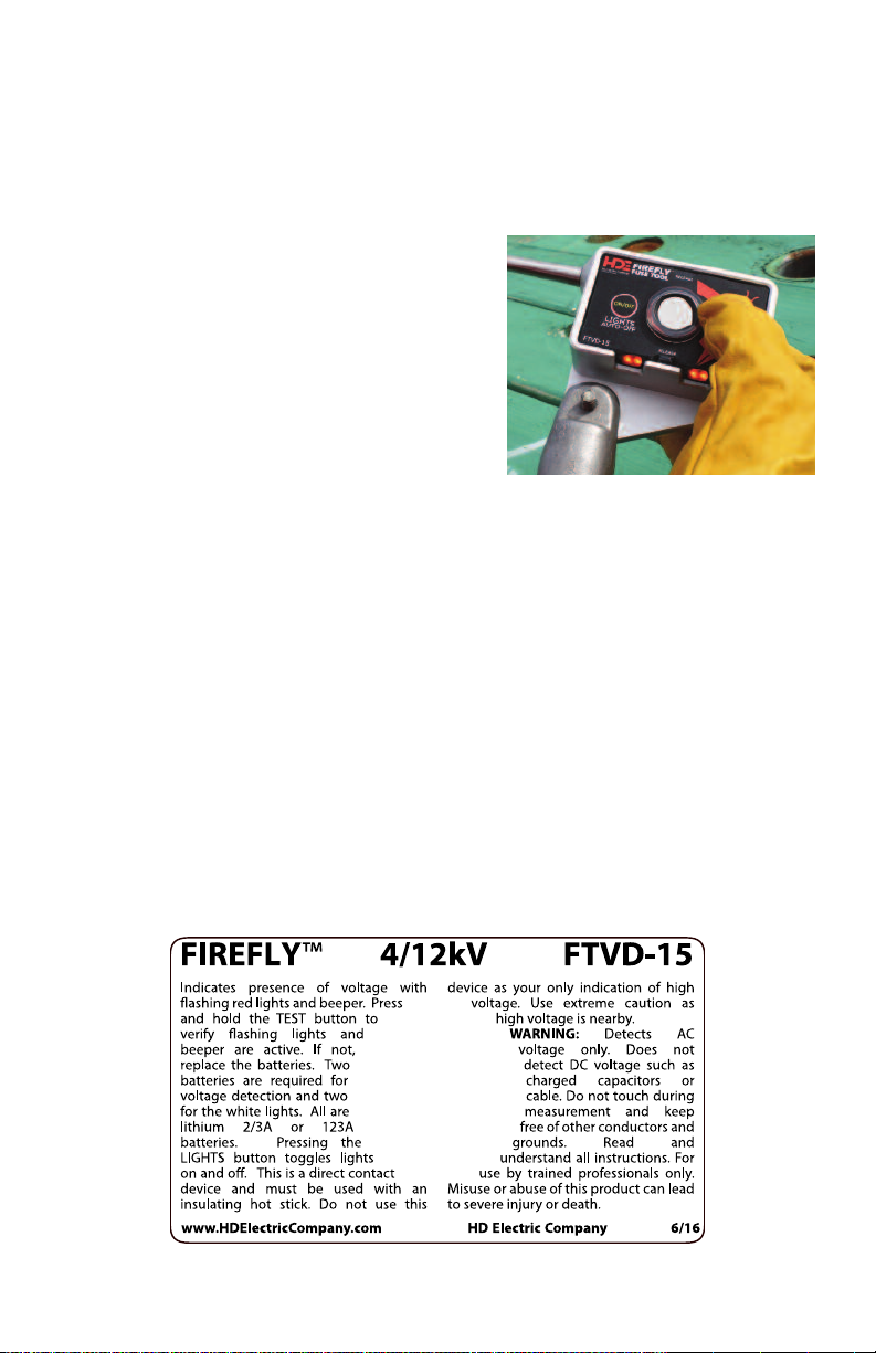
1) Push and hold the self-test button on
the front panel to operate the self-test.
The red (alarm) LED lights will flash
and the buzzer will beep. The unit
is ready for operation (Figure 1).
2) If pressing the test button does not cause
the events listed in Step 1, the unit should
not be placed in operation. The battery
may need replacement, see Battery
Replacement section (page 8). If changing
the battery does not produce the results
shown in Step 1, remove the unit from service
and send in for repair.
3) After completing the voltage detection on the conductor (see next section), always
confirm proper function of the FireFly Detector by completing Step 1 again. If the
self-test does not function as above, DO NOT assume that the test results are correct.
Re-test the conductor, preferably with a different FireFly Detector.
Figure 1
4) Verify the operation of the white lights by pressing the Lights ON/OFF button.
Verify both the top and side white lights turn on. Replace the two Lights batteries
if the lights do not come on (page 8).
NOTE: Never use the self-test if the FireFly Detector is in contact with any voltage source.
5
Page 6
INSTRUCTIONS FOR USE
Situations To Avoid
Within certain situations and because of various system configurations, electrical field
interference capable of affecting the operation of the FireFly Voltage Detector may
occur. Within these areas it is imperative that you be aware of and identify all such
conditions which may exist. Some examples of these situations are discussed here.
1) 90° CORNER CONFIGURATIONS: Using the FireFly Detector on the inside of 90°
corners may cause reduced voltage sensitivity or a failure to indicate voltage.
2) SAME PHASE INTERFERENCE: When two conductors of the same phase are
in close proximity to one another, the field generated could shield the FireFly
Detector, causing it not to operate.
3) OPPOSITE PHASE INTERFERENCE: This condition may occur when testing
a grounded and de-energized conductor which is in close proximity to
a live, ungrounded conductor. In this situation the FireFly Detector may indicate live
voltage when the conductor being contacted is at ground potential.
NOTE: Only use the FireFly Detector within the voltage range specified on the product
label. Do not use the FireFly Detector above or below the product label rating.
DANGER: Never allow the body of the FireFly Detector to bridge across, or come
in contact with, another conductor or grounded point.
6
Page 7

OPERATION
NOTE: Direct, metal-to-metal contact with the conductor must be made for the
FireFly Voltage Detector to operate correctly.
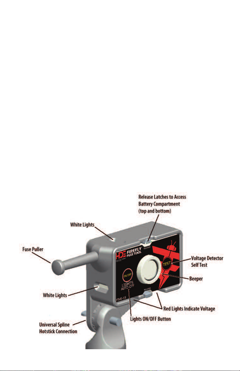
1) Place the FireFly Detector at the end of a hotstick adequate for protection for the
voltage range being tested. Company, OSHA and industry safety procedures
MUST BE FOLLOWED AT ALL TIMES. Connect the detector to the hotstick by
way of the built-in universal spline, making certain it is securely attached.
2) If the FireFly Detector will be used at night or in the dark, test the Lights before
use. The lights will shut off automatically 10 minutes after the most recent
voltage detection or self-test, or they can be turned off manually.
3) Place the FireFly Detector in direct contact with the conductor being tested for
voltage or inside the loop of the fuse cutout or switch. The FireFly Detector
should be positioned as close to a 90° orientation (perpendicular) to the fuse
or switch as possible. If the conductor is energized, the detector will give both
an audible (beeping tone) and visual (red blinking lights) indication. If the
conductor is not energized no signal is given.
When operating within the unit’s voltage range (see product label), the FireFly
Detector will provide both an audible and visual alarm upon making contact
with an energized conductor. The FireFly Detector unit will not give an alarm
due to induced voltage on de-energized conductors, unless the induced
voltage level exceeds the threshold voltage of the detector.
4) Test the FireFly Detector for proper voltage detection after each use by
pushing the TEST button. See the Self-Test Operation section (page 5).
The PT-FTVD Proof Tester FireFly Voltage Detector Tester can also be used to
test the FireFly on a known voltage source before and after use (page 10).
7
Page 8
BATTERY REPLACEMENT
Replace the four batteries as needed with IEC type CR17345 including Duracell® 123,
Panasonic® CR123A and Energizer® 123. Note: Panasonic® type CR17335 or BR-2/3A
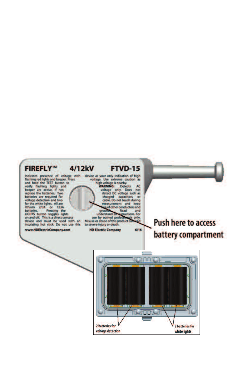
are not acceptable replacements. Two of the four batteries power the voltage detector
and the other two power the white lights. Always replace the two batteries for each
function in pairs, but it is not necessary to replace all four batteries at the same time.
1) Remove the molded plastic inner housing from the aluminum outer housing by
pressing and holding the two latches on the front of the unit and pushing through
the hole in the back of the unit.
2) Pull the battery cover off of the back of the molded housing.
3) Replace batteries as needed for the voltage detector and/or the white lights. Verify
correct battery polarity.
4) Replace the battery compartment cover and push the molded housing back into
the aluminum holder right side up. Ensure both latches snap into place.
8
Page 9

MAINTENANCE AND CARE
STORAGE - It is recommended for protection of the FireFly Detector that you always
store it and its accessories in the carrying bag provided. If a prolonged period of
storage is anticipated (six or more months), remove the batteries. Remember to
replace the batteries prior to using the FireFly Detector again.
CLEANLINESS - The aluminum outer housing is very rugged, but it should be kept
clean and free of dirt, grease and any other foreign materials. The inner plastic housing
should also be kept clean and dry. If either housing surface integrity has been
compromised in any way, return the FireFly Detector to the factory for repair or
replacement. Do not use.
DAMAGE - If you suspect any mechanical or electrical damage, do not use the
FireFly Detector and arrange for repair by returning to the factory.
BATTERY REPLACEMENT - See Battery Replacement section (page 8)
for additional information.
CALIBRATION & TESTING - It is recommended that every twelve months the
FireFly Detector is sent in for testing, cleaning and inspection. We recommend
this to be done at a factory trained repair facility, the HD Electric Company factory,
or other qualified location.
Minimal maintenance is required for the FireFly Detector. The carrying bag that is supplied
with the unit is recommended for storage of the FireFly Detector when it is not in use.
TECHNICAL SPECIFICATIONS
ENVIRONMENTAL CONDITIONS
CONDITIONS - Indoor and outdoor use
ALTITUDE - Up to 6,566 ft. (2000M)
OPERATING TEMPERATURE -40°F to +120°F (-40°C to +49°C)
HUMIDITY - 95% to 49°C (non-condensing)
MEASUREMENT CATEGORY IV
OVERVOLTAGE CATEGORY IV
ENCLOSURE MATERIAL - Aluminum, polycarbonite
DIMENSIONS:
LENGTH - 6 in. (15cm), Width 1.2 in. (3cm), Height 6 in. (15cm)
WEIGHT - 1 lb. (454g)
BATTERY LIFE - Voltage detection - up to 40 hours continuous alert
White lights - up to 8 hours continuous
BATTERY - 3V lithium, ANSI-5018LC, IEC-CR17345
VOLTAGE DETECTION RANGE - Voltage ranges available from
4kV to 35kV system voltage, 50/60Hz.
9
Page 10
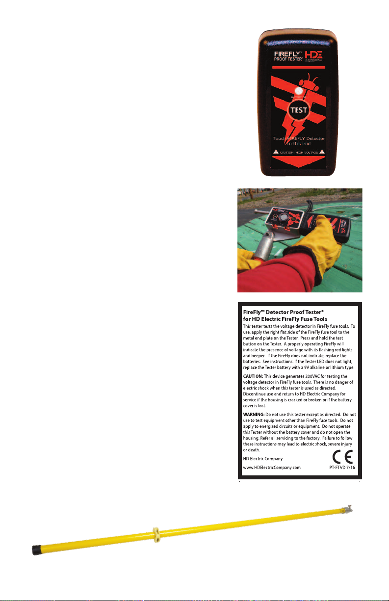
OPTIONAL ACCESSORIES
PT-FTVD TESTER FOR FIREFLY DETECTORS
The PT-FTVD Proof Tester® FireFly Detector Tester
is for use on all FireFly Detector models. This
tester generates high voltage AC for testing
the FireFly Voltage Detector.
To use, apply the metal plate on the bottom of the
FireFly Tester to the right side of the Firefly Detector
housing as shown. Press and hold the TEST button
on the Proof Tester. A properly operating FireFly
Detector will signal the presence of voltage with
both the beeper and red lights. If the FireFly Voltage
Detector does not operate, replace the Voltage
Detector batteries, per the instructions (page 8).
If the Proof Tester LED does not light, replace the
Proof Tester battery with a 9V lithium
or alkaline type battery.
CAUTION: This device generates high
voltage AC for testing the voltage detection
function in FireFly Detectors. There is no
danger of electric shock when this Tester
is used as directed. Discontinue use and
return to HD Electric Company for service
if the housing is cracked or broken,
or if the battery cover is lost.
WARNING: Do not use this Tester except
as directed. Do not use to test equipment
other than specified FireFly Voltage Detectors.
Do not apply to energized circuits or equipment.
Do not operate this Tester without the
battery cover and do not open the housing.
Refer all servicing to the factory. Failure to
follow these instructions may lead to
electric shock, severe injury or death.
HOTSTICKS
A range of hotsticks are available in lengths starting
at 4’. Contact HD Electric for more details.
10
Page 11

11
Page 12

LIMITED WARRANTY AND LIMITATION OF LIABILITY
his warranty applies to all products sold by HD Electric Company (the "Products"); provided, however, that the term Products does not include any
T
hird party products purchased through HD Electric Company, for which no warranties are made (the "Third Party Products"). Third Party Products
t
ay be subject to a separate manufacturer's warranty; [should you have any question regarding whether a separate warranty applies, please contact
m
D Electric Company].
H
OTICE: READ THIS LIMITATION OF WARRANTY AND LIABILITY BEFORE BUYING OR USING THE PRODUCTS CONTAINED HEREIN.
N
t is impossible to eliminate all risks associated with the use of the Products. Risks of serious injury or death, including risks associated with electrocution,
I
rcing and thermal burns, are inherent in work in and around energized electrical systems. Such risks arise from the wide variety of electrical systems
a
nd equipment to which Products may be applied, the manner of use or application, weather and environmental conditions or other unknown factors,
a
ll of which are beyond the control of HD Electric Company.
a
D Electric Company does not agree to be an insurer of these risks, and shall have no liability for any claims arising from such risks.
H
HEN YOU BUY OR USE THESE PRODUCTS, YOU AGREE TO ACCEPT THESE RISKS.
W
D Electric Company warrants to the original purchaser that the Products (excluding any third party products purchased through HD Electric Company,
H
or which no warranties are made) will be free from defects in material and workmanship, under normal use and regular service, and preventative
f
aintenance for a period of one (1) year (ten (10) years for HDE Capacitor Controls) from the date of shipment (the “Warranty Period”). Should any failure
m
o conform with this warranty be found during the Warranty Period, you must notify HD Electric Company of your claim within thirty (30) days of discovery,
t
nd within the Warranty Period. Your failure to give notice of claims of breach of warranty within the Warranty Period shall be deemed an absolute and
a
nconditional waiver of claims for such defects. HD Electric Company will have no responsibility to honor claims received after the date the applicable
u
arranty Period expires.
W
pon notice of your claim, HD Electric Company will provide a return authorization number, and further instructions on how to return the product for
U
ervice. You must follow HD Electric Company’s instruction. You are responsible for all Product removal, handling, re-installation, and shipping (both
s
o and from HD Electric Company). Products returned for repair, as well as repaired or replacement Products shall be sent postage / freight prepaid. After
t
eceipt of a product which HD Electric Company determines is defective, HD Electric will, at its option, either (1) repair (or authorize the repair of) the
r
Product or (2) replace the Product, subject to the following: The Products are made using parts sourced from a variety of manufacturers. Due to the rapidly
changing technology environment, parts may become obsolete / unavailable over time (end of life). In the event that a Product cannot be repaired or
replaced due to unavailability of parts, HD Electric Company will use commercially reasonable efforts to obtain substitute parts or conduct work around
design, but cannot guarantee its ability to do so.
Items not found defective will be returned at your expense, or failing receipt of instruction from you on return of such items within five (5) business days
of our notice to you that the product is not defective, HD Electric may dispose of the product at its discretion and with no liability to you. HD Electric
Company’s determination of defects is final. Products repaired or replaced during the Warranty Period shall be covered by the foregoing warranties for
the remainder of the original Warranty Period or ninety (90) days from the date of delivery of the repaired or replaced Products, whichever is longer.
LIMITATIONS:
This warranty is void in the event of misuse, alteration, faulty installation, or misapplication of the product.
This warranty does not cover failure of product or components due to any ACT OF NATURE; lightning, floods, hurricanes, tornadoes or any other such
catastrophic events.
HD Electric Company does not warrant any third party products or associated hardware or their performance or suitability for use and application. Such
items are provided “as-is”.
All repairs must be authorized by HD Electric Company. Unauthorized repairs will not be reimbursed under any circumstances.
HD Electric Company is not required to make replacement or loaner equipment available while Products are being repaired or replaced, or to compensate
you for any in/out labor charges or expenses associated with removal, handling or re-installation of the Products.
TO THE MAXIMUM EXTENT PERMITTED BY LAW, THIS WARRANTY AND THE REMEDIES SET FORTH ABOVE ARE EXCLUSIVE AND IN LIEU OF ALL OTHER
WARRANTIES, REMEDIES AND CONDITIONS, WHETHER ORAL OR WRITTEN, EXPRESS OR IMPLIED. HD ELECTRIC EXPRESSLY DISCLAIMS ALL OTHER
WARRANTIES OF ANY KIND, EXPRESS OR IMPLIED, INCLUDING WITHOUT LIMITATION IMPLIED WARRANTIES OF FITNESS FOR A PARTICULAR PURPOSE,
MERCHANTABILITY AND NON-INFRINGEMENT.
IN NO EVENT SHALL HD ELECTRIC COMPANY BE LIABLE FOR ANY INDIRECT, INCIDENTAL, CONSEQUENTIAL OR SPECIAL DAMAGES RESULTING FROM THE
USE OR HANDLING OF THESE PRODUCTS. THIS SHALL INCLUDE BUT, NOT LIMITED TO, LOST PROFITS OR REVENUE, LOSS OF USE OF THE PRODUCTS,
COST OF SUBSTITUTE PRODUCTS, FACILITIES OR SERVICES, OR DOWNTIME.
IN NO EVENT SHALL HD ELECTRIC COMPANY HAVE ANY LIABILITY FOR ANY THIRD PARTY PRODUCTS OR ASSOCIATED HARDWARE, OR
CUSTOMER-OWNED SYSTEMS, EQUIPMENT OR SOFTWARE.
HD Electric Company must have prompt notice of any claim so that an immediate product inspection and investigation can be made. Buyer and all
users shall promptly notify HD Electric Company of any claims, whether based on contract, negligence, strict liability, or other tort or otherwise be barred
from any remedy.
HD Electric Company is committed to ongoing review and improvement of its product lines,
and thus reserves the right to modify product design and specifications without notice.
Duracell® is a registered trademark of The Duracell Company. Panasonic® is a registered trademark
of Panasonic Corporation.Energizer® is a registered trademark of Energizer Brands, LLC.
HD Electric Company® products are available through HDE® sales representatives worldwide.
Printed in U.S.A. © HD Electric Company 2017 • Bulletin No. FF IM-100e
 Loading...