

Page 1

802.11g In-wall WLAN
Access Point
Model No. HD24613
User Guide
HD24613_UG_001
i
Page 2

Federal Communication Commission Interference Statement
This equipment has been tested and found to comply with the limits for a Class B digital device, pursuant to Part 15 of the FCC Rules. These limits are designed to provide reasonable protection against
harmful interference in a residential installation. This equipment generates, uses and can radiated radio frequenc y energy and, if not install ed and used in accordance with the instructions, may cause
harmful interference to radio communications. However, there is no guarantee that interference will
not occur in a particular installation. If this equipment does cause harmful interference to radio or television reception, which can be determined by turning the equipment off and on, the user is encouraged to try to correct the interference by one of the following measures:
z Reorient or relocate the receiving antenna.
z Increase the separation between the e qui pme nt an d re ce iver .
z Connect the equipment into an outlet on a circuit different from that to which the receiver is
connected.
z Consult the dealer or an experienced radio/TV technician for help.
FCC Caution: To assure continued compliance, (example – use only shielded interface cables when
connecting to computer or peripheral devices). Any changes or modifications not expressly approved
by the party responsible for compliance could void the user’s authority to operate this equipment.
This transmitter must not be co-located or operating in conjunction with any other antenna or transmitter.
FCC Radiation Exposure Statement
This equipment complies with FCC radiation exposure limits set forth for an uncontrolled environment. This equipment should be installed and operated with minimum distance 20 cm between the radiator & your body.
This device complies with Part 15 of the FCC Rules. Operation is subject to the following two conditions: (1) This device may not cause harmful interference, and (2) this device must accept any interference received, including interference that may cause undesired operation.
ii
Page 3

R&TTE Compliance Statement
This equipment complies with all the requirements of DIRECTIVE 1999/5/C E OF THE EUR OPE AN
PARLIAMENT AND THE COUNCIL OF 9 March 199 9 on radio equipment and teleco mmunicati on
terminal equipment and the mutual recognition of their conformity (R&TTE).
The R&TTE Directive repeals and repl aces in the dir ective 98/13/ EEC (Teleco mmunicati ons Termi nal Equipment and Satellite Earth Station Equipment) as of April 8,2000.
Safety
This equipment is designed with the utmost care for the safety of those who install and use it. However, special attention must be paid to the da ngers of electric shock and static electricity when working
with electrical equipment. All g uidelines of this and of the co mputer manufacture must ther efore be
allowed at all times to ensure the safe use of the equipment.
EU Countries Intended for Use
The ETSI version of this device is intended for home and office use in Austri a, Belgium, Denmark,
Finland, France (with Frequency channel restrictions), Germany, Greece, Ireland, Italy, Luxembourg,
Portugal, Spain, Sweden, The Netherlands, and United Kingdom.
The ETSI version of this device is also a uthorized fo r use in EFTA member states Norway and Switzerland.
EU Countries Not Intended for Use
None.
iii
Page 4

Table of Contents
1. Introduction ......................................................................................................................... 1
1.1. Overview ................................................................................................................... 1
1.2. Features .................................................................................................................... 1
1.3. LED Definitions ......................................................................................................... 3
2. First-Time Installation and Configuration ............................................................................ 4
2.1. Power ........................................................................................................................ 4
2.2. Installing the HD24613 ............................................................................................. 4
2.3. Connecting a Managing Computer ........................................................................... 5
2.4. Configuring the AP .................................................................................................... 5
2.4.1. Login ............................................................................................................... 6
2.4.2. Selecting Mode ............................................................................................... 7
2.4.3. Configuring TCP/IP Settings ........................................................................... 8
2.4.4. Configure IEEE 802.11 Settings ..................................................................... 9
2.4.5. Review and Apply Settings ........................................................................... 10
2.5. Setting up Client Computers ................................................................................... 10
2.5.1. Configure IEEE 802.11 Settings ................................................................... 10
2.5.2. Configure TCP/IP-Related Settings .............................................................. 11
2.6. Confirm Settings of the HD24613 and Client Computers ....................................... 11
2.6.1. Checking if the IEEE 802.11b-Related Settings Work .................................. 11
2.6.2. Checking if the TCP/IP-Related Settings Work ............................................ 11
3. Advanced Network Management ...................................................................................... 12
3.1. Overview ................................................................................................................. 12
3.1.1. Menu Structure ............................................................................................. 12
3.1.2. Save, Save & Restart, and Cancel Commands ............................................ 13
3.1.3. Home and Refresh Commands .................................................................... 14
3.2. Viewing Status ........................................................................................................ 15
3.2.1. Associated Wireless Clients ......................................................................... 15
3.2.2. Current DHCP Mappings .............................................................................. 15
3.2.3. System Log ................................................................................................... 15
3.2.4. Link Monitor .................................................................................................. 16
3.3. General Operations ................................................................................................ 16
3.3.1. Specifying Operational Mode ....................................................................... 16
3.3.2. Changing Password ..................................................................................... 18
3.3.3. Managing Firmware ...................................................................................... 18
3.3.3.1. Upgrading Firmware by HTTP ............................................................ 18
3.3.3.2. Backing up and Restoring Configuration Settings by HTTP ............... 19
3.3.3.3. Upgrading Firmware by TFTP ............................................................ 19
3.3.3.4. Backing up and Restoring Configuration Settings by TFTP ............... 21
3.3.3.5. Resetting Configuration to Factory Defaults ....................................... 22
3.4. Configuring TCP/IP Related Settings ..................................................................... 22
3.4.1. Addressing .................................................................................................... 22
3.4.2. DHCP Server ................................................................................................ 23
3.4.2.1. Basic ................................................................................................... 23
3.4.2.2. Static DHCP Mappings ....................................................................... 23
3.5. Configuring IEEE 802.11 Related Settings ............................................................. 24
3.5.1. Communication ............................................................................................. 24
3.5.1.1. Basic ................................................................................................... 24
3.5.1.2. Link Integrity ....................................................................................... 25
3.5.1.3. Association Control ............................................................................ 25
3.5.1.4. Load Balancing ................................................................................... 25
3.5.1.5. Wireless Distribution System .............................................................. 26
3.5.2. Security ......................................................................................................... 28
3.5.2.1. Selecting Wireless Security Mode ...................................................... 29
iv
Page 5

3.5.2.2. MAC-Address-Based Access Control ................................................ 31
3.5.3. IEEE 802.1x/RADIUS ................................................................................... 33
3.6. Advanced Settings .................................................................................................. 35
3.6.1. Packet Filters ................................................................................................ 35
3.6.1.1. Ethernet Type Filters .......................................................................... 35
3.6.1.2. IP Protocol Filters ............................................................................... 35
3.6.1.3. TCP/UDP Port Filters ......................................................................... 36
3.6.2. Management ................................................................................................. 36
3.6.2.1. UPnP .................................................................................................. 36
3.6.2.2. System Log ........................................................................................ 37
3.6.2.3. SNMP ................................................................................................. 37
Appendix A: Default Settings ................................................................................................ 39
Appendix B: Troubleshooting ................................................................................................ 40
B-1: Wireless Settings Problems ................................................................................... 40
B-2: TCP/IP Settings Problems ..................................................................................... 41
v
Page 6

1. Introduction
1.1. Overview
The HD24613 modular WLAN access point (AP) enables 802.11g or 802.11b client computers to
access the resources on an Ethernet network wirelessly or wired. It conveniently fits into standard
wall outlets and only takes a few minutes to install and configure for use. The HD24613 has a
built-in browser-based management application offering an easy to follow setup-wizard for novice
wireless users as well as comprehensiv e settings for more advanced users and/or network administrators.
1.2. Features
z HD24613 Firmware Features
Operational Modes
AP/Bridge. This mode provides both Access Point and Static LAN-to-L AN Bridg-
ing functionality. The static LAN-to-LAN bridging function is supported through
Wireless Distribution System (WDS).
AP Client. This mode is for Dynamic LAN-to-LAN Bridging. The AP Client auto-
matically establishes bridge links with APs from any vendor.
RF Type Selection.
IEEE 802.11b only, IEEE 802.11g only, or mixed mode (802.11g and 802.11b simultaneously).
64-bit and 128-bit WEP (Wired Equivalent Privacy).
encryption.
Enabling/Disabling SSID Broadcasts.
administrator can enable or disable the SSID broadcasts functionality for security reasons.
When the SSID broadcast functionality is disabled, a client computer cannot connect to the
HD24613 with “blank” network name (SSID, Service Set ID); the correct SSID has to be
specified on client computers.
MAC-address-based Access Control.
can be configured to block unauthorized wireless client computers based on MAC (Media
Access Control) addresses. Additionally, an ACL (Access Control List) can be downloaded
from a TFTP server.
The RF type of the WLAN interface can be configured to work in
For authentication and data
When the HD24613 is in AP/Bridge mode, the
When the HD24613 is in AP/Bridge mode, it
IEEE 802.1x/RADIUS.
to authenticate wireless users and distribute encryption keys dynamically by IEEE 802.1x
Port-Based Network Access Control and RADIUS (Remote Authentication Dial-In User
Service).
WPA (Wi-Fi Protected Access).
by the Wi-Fi Alliance (http://www.wi-fi.org
full WPA mode are supported. WPA is composed of TKIP (Temporal Key Integrity Protocol) and IEEE 802.1x and serves as a successor to WEP for better WLAN security.
1
When the HD24613 is in AP/Bridge mode, it can be configured
The HD24613 supports the WPA standard proposed
). Both WPA-PSK (Pre-Shared Key) mode and
Page 7

Repeater. When the HD24613 is in AP/Bridge mode, it can communicate with other APs
or wireless bridges via WDS (Wireless Distribution System). Therefore, a HD24613 can
wirelessly forward packets from wireless clients to another HD24613. Then the second
HD24613 forwards the packets to the Ethernet network.
Wireless Client Isolation.
When the HD24613 is in AP/Bridge mode, wireless-to-wireless traffic can be blocked so that the wireless clients cannot see each other.
This capability can be used in hotspots applications to prevent wireless hackers from attacking other wireless users’ computers.
AP Load Balancing.
Several HD24613’s can form a load-balancing group. Within a
group, wireless client associations and tr affic load can be shared among the de vices. This
function is available when the HD24613 is in AP/Bridge mode.
Transmit Power Control.
Transmit power of the HD24613’s RF module can be ad-
justed to desired RF coverage.
Link Integrity.
When the HD24613 is in AP/Bridge mode and its Ethernet LAN interface
is detected to be disconnected from the wired network, all currently associated wireless
clients are disassociated by the HD24613 and no wireless client can associate with it.
Association Control.
When the HD24613 is in AP/Bridge mode, it can be configured to
deny association requests when it has served too many wireless clients or traffic load is too
heavy.
Associated Wireless Clients Status.
When the HD24613 is in AP/Bridge mode, it
can show the status of all wireless clients that are currently associated or ‘connect ed’ .
Auto Channel Selection.
The auto channel sele ction feature allows the device to auto-
matically select the channel that will provide optimum performance on powering up the
HD24613.
z DHCP client. The HD24613 can automatically obtain an IP address from a DHCP server.
z DHCP server. The HD24613 can automatically assign IP addresses to computers or other de-
vices by DHCP (Dynamic Host Configuration Protocol).
Static DHCP Mappings.
The administrator can specify static IP address to MAC ad-
dress mappings so that IP addresses are always assigned to the hosts with the specified
MAC addresses.
Showing Current DHCP Mappings.
Displays which IP address is assigned to which
host identified by an MAC address.
z Packet Filtering. The HD24613 provides Layer 2, Layer 3, and Layer 4 filtering capabilities.
z Firmware Management Tools
Firmware Upgrade.
The firmware of the HD24613 can be upgraded in the following
methods:
TFTP-based. Upgrading firmware by TFTP (Trivial File Transfer Protocol).
HTTP-based. Upgrading firmware by HTTP (HyperText Transfer Protocol).
2
Page 8

Configuration Backup. The configuration settings of the HD24613 can be backed up to
a file via TFTP
or HTTP for later restoring.
Configuration Reset.
ry-default values.
z Management
Browser-based Network Manager
Web browser. The management protocol is HTTP (Hyper Text Transfer Protocol)-based.
SNMP.
IEEE 802.1x, and Private Enterprise MIB are supported.
UPnP.
can locate the HD24613 in My Network Places and use a Web browser to configure it.
System Log.
Local log. System events are logged to the on-board RAM of the HD24613 and can
Remote log by SNMP trap. Systems events are sent in the form of SNMP traps to
z Power over Ethernet. Power is supplied to the HD24613 via an Ethernet cable using an
802.3af compliant power injector.
SNMP (Simple Network Management Protocol) MIB I, MIB II, IEEE 802.1d,
The HD2 4613 responds to UPnP discovery messages so that a Windows XP user
For system operational status monitoring.
be viewed using a Web browser.
a remote SNMP management server.
Clears current configuration settings and restores to facto-
for configuring and monitoring the HD24613 via a
z Hardware Watchdog Timer. If the firmware “hangs” in an invalid state, the hardware
watchdog timer will detect this situation and restart the HD24613. This way, the HD24613 can
provide continuous services.
1.3. LED Definitions
There are several LED indicators on the front of the HD24613. Please refer to the definitions below:
A. Power: Green, solid when receiving power
B. WAN: Green, solid when connected, flashing when data activity
C. Wireless: Green, solid when on, flashing when wireless data activity
3
Page 9

D. RJ-45 LAN port
Amber, solid when LAN connection
Green, solid when LAN connection, flashing when activity
2. First-Time Installation and Configuration
2.1. Power
The HD24613 is powered using PoE (Power over Ethernet). The HD24613 automatically selects the
suitable power supply.
To power the AP by PoE:
1. Plug one connector of an Ethernet cable to an available port of a PoE injector or switch.
2. Plug the other connector of the Ethernet cable to the WAN port on the rear of the HD24613.
NOTE: The HD24613 is 802.3af compatible.
2.2. Installing the HD24613
The HD24613 has two options for installation: desktop/flat surface or into a standard Ethernet wall
jack.
Desktop or flat surface:
1. Remove the HD24613 from the box and snap apart the two pieces of the screw less faceplate
that are affixed to the HD24613.
2. Place the HD24613 in desired location upon the desk or flat surface.
3. Using the single-port PoE Injector, connect on e end of an Ethernet LA N cable from a LAN port
on the network router or switch and the opposite end to the port marked “Data In”. Use another
Ethernet LAN cable to connect th e port marked “Data Out” to the WAN port (on rear ) of the
HD24613.
4. Plug the single-port PoE power cord into an electrical outlet.
5. Check the LED indication lights. All three (Power, WAN, Wireless) should be properly lit.
Ethernet Wall Jack:
1. Remove the Ethernet wall jack faceplate and measure the depth of wall box.
2. Adjust the top and bottom brackets of the HD24613 accordingly.
3. Separate the cover (top) of the HD24613 faceplate from the frame (bottom).
4. With the HD24613 still in the faceplate frame, plug the wall jack LAN cable to the WAN port of
the HD24613. All three green LE Ds on the HD24613 should be lit if properly connected to a
router/switch and PoE power supply. If “yes”, proceed to step 5.
4
Page 10
5. Slowly insert the HD24613 into the wall box until the faceplate frame is flush to the wall.
6. Fasten both the HD24613 and the faceplate frame to the wall box with screws provided.
7. Line-up and push the faceplate cover onto the frame until it snaps securely into place.
2.3. Connecting a Managing Computer
To configure the HD24613 using the Advanced option, a managing computer with a Web browser is
needed.
NOTE: If you are using the browser, Opera, to co nfigure the HD24613, click the menu item File,
click Preferences..., click File types, and edit the MIME type, text/html, to add a file extension
“.sht” so that Opera can work properly with the Web management pages of the AP.
Since the configuration/management protocol is HTT P-based, make sure that the IP address of the
managing computer and the IP address of the managed AP are in the same IP subnet (the default
IP address of the HD24613 is 192.168.100.1 and the default subnet mask is 255.255.255.0.)
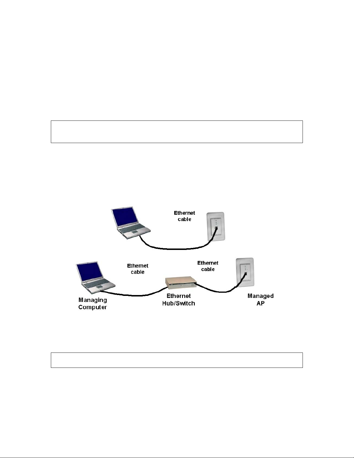
To connect the Ethernet managing computer and the managed HD24613 for first-time configuration,
you have two choices as illustrated in Fig. 1.
Fig. 1. Connecting a managing computer and the HD24613 via Ethernet
You can use either a standard Ethernet cable (included in the package) or a switch/hu b with two normal Ethernet cables.
NOTE: One connector of the Ethernet cable must be plugged into the HD2 4613 WAN port for con-
figuration.
2.4. Configuring the AP
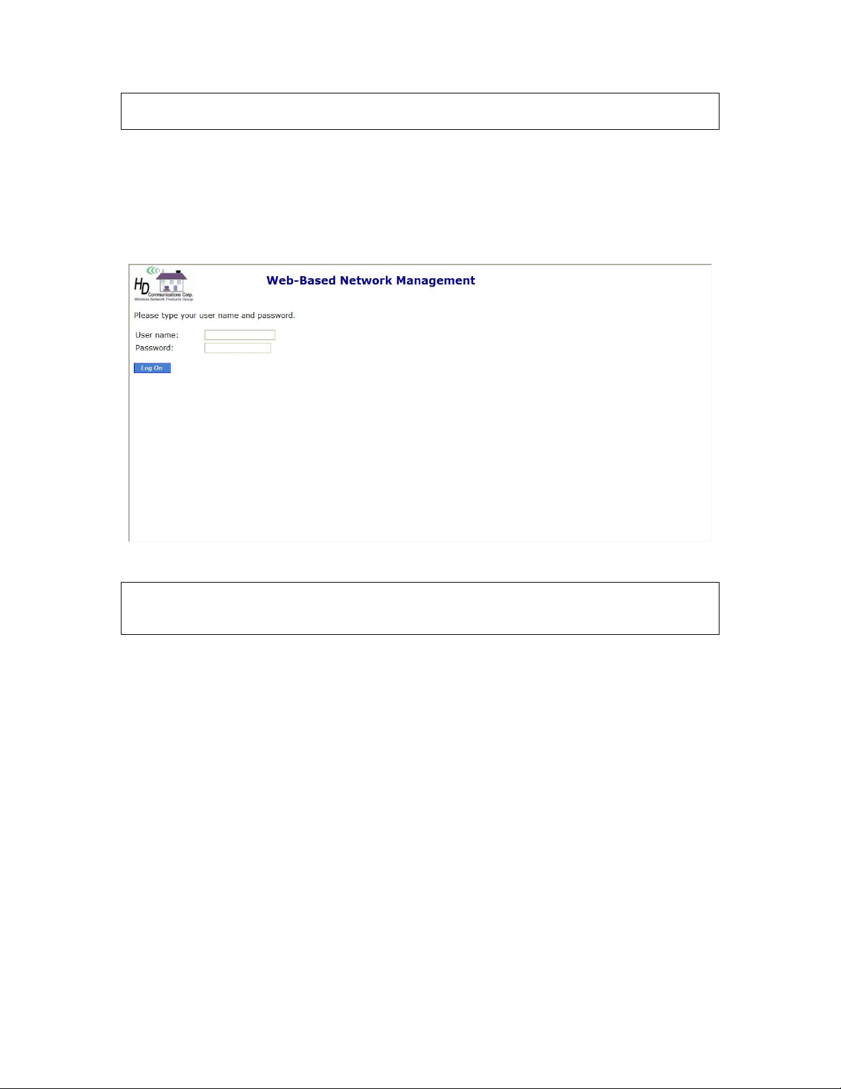
After the IP addressing issue is resolved, launch a Web browser on the managing computer. Then, go
to “http://192.168.100.1” to access the Web-based Network Manager login page.
5
Page 11
TIP: The HD24613 can be reached by its host name using a Web browser. For example, if the
HD24613 is named “AP”, you can use the URL “http://AP” to access.
2.4.1. Login
Before the Home page is shown, you will be prompted to enter the user name and password to gain
the right to access the Web-based Network Manager. For first-time configuration, use the default user
name “root” and default password “root”, respectively.
Fig. 2. The Login page
NOTE: It is strongly recommended that the password be changed for security reasons. On the start
page, click the General, Password link to change the value of the password (see Section 3.3.1 for
more information).
6
Page 12

Once you have successfully logged in, the Home page opens. Click the Setup Wizard option to
quickly setup the HD24613 for use in 4 steps. Alternately, click Advanced Setup to manually setup.
Fig. 3. The Home page
2.4.2. Selecting Mode
The HD24613 supports two operational modes:
AP/Bridge. This mode provides both Access Point and Static LAN-to-LAN Bridging
functionality. The static LAN-to-LAN bridging function is supported through Wireless
Distribution System (WDS).
AP Client. This mode is for Dynamic LAN-to-LAN Bridging. The AP Client automati-
cally establishes bridge links with APs from any vendors.
Fig. 4. Operational mode settings
1. Click on General from the side menu, and then select Operational Mode.
2. Select an operational mode and click Save to apply the setting.
In either mode, the HD24613 forwards packets between its Ethernet interface and wireless interface
for wired hosts on the Ethernet side and wireless host(s) on the wireless side.
There are two types of wireless links as specified by the IEEE 802.11 standard.
7
Page 13

STA-AP. This type of wireless li nk is establi shed bet ween an IEEE 802.11 Stat ion (STA)
and an IEEE 802.11 Access Point (AP). An STA is usually a client computer (PC or PDA)
with a WLAN network interface card (NIC). The AP Client mode is actually an STA.
WDS. This type of wireless link is established between two IEEE 802.11 HD24613’s.
Wireless packets transmitted along the WDS link comply with the IEEE 802.11 WDS
(Wireless Distribution System) format at the link layer.
The relationships among the operational modes and the wireless link types are shown in the following
table:
AP/Bridge AP Client
AP/Bridge WDS STA-AP
AP Client STA-AP
Table 1. Operational modes vs. wireless link types.
To establish a static bridge link based on WDS, the AP/bridges at both end of the WDS link must be
manually configured with each other’s MAC addresses (see Secti on 3. 5.1. 5 for more inf orma tion) . T o
establish a dynamic bridge link between an HD24613 and an AP Client, both devices have to be configured with the same SSID and WEP settings. The AP Client automatically scans for any HD24613
that is using the matched SSID and establishes a bridge link with the scanned HD24613.
NOTE: Although it’s more convenient to use dynamic bridging, it has a limitation—the AP Client
only can forward TCP/IP packets between its wirele ss interface and Ether net interface; other ty pe of
traffic (such as IPX and AppleTalk) is not forwarded.
TIP: When the HD24613 is configured to be in AP Client, it can be used as an Ethernet-to-wireless
network adapter. For example, a notebook computer equipped with an Ethernet adapter can be connected to this device with a crossover Ethernet cable for wireless connectivity to another access point.
2.4.3. Configuring TCP/IP Settings
The IP address can be manually set or automatically assigned by a DHCP server on the LAN. If you
are manually setting the IP address, Subnet mask, and Default gateway settings, set them appro-
priately, so that they comply with your LAN environment. In addition, you can specify the Host name
and Domain (DNS suffix) of the AP.
8
Page 14
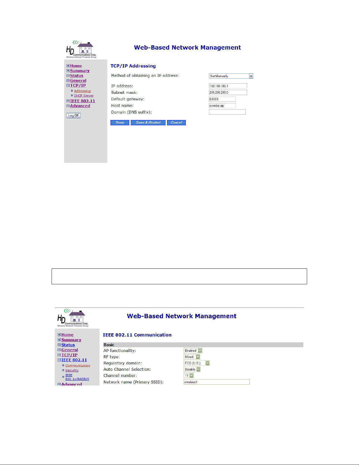
Fig. 5. TCP/IP settings
1. Click on TCP/IP from the side menu and select Addressing.
2. When you have finished making changes, click Save or Save & Restart.
2.4.4. Configure IEEE 802.11 Settings
The Network Manager utility allows the user to configure IEEE 802.11b-related communication settings, including Regulatory domain, Channel number, and Network name (SSID) of the HD24613.
The number of available RF channels depends on local regulations; therefore you have to choose an
appropriate regulatory domain to comply with local regulations. The SSID of a wireless client com-
puter and the SSID of the HD24613 must be identical for them to communicate with each other.
NOTE: Put a che ck in the Auto Channel Selection checkbox to allow the Frequency Channel of
the HD24613 to be automatically set.
Fig. 6. IEEE 802.11 communication settings
1. Click on IEEE 802.11 from the side menu, and then select Communication.
2. When you have finished, scroll to the bottom of the screen and click either Save or Save &
9
Page 15
Restart.
2.4.5. Review and Apply Settings
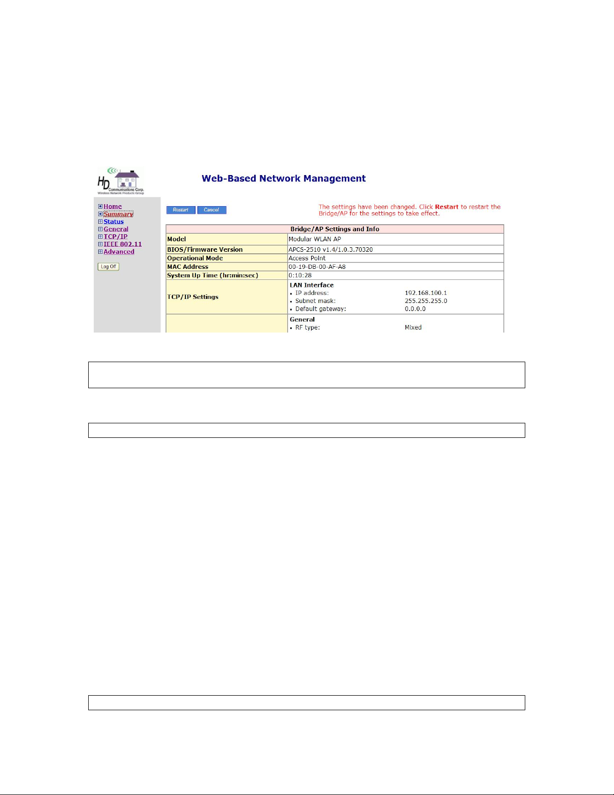
On the Summary page, you can review all the settings you have ma de. C hanges are hig hlighted in red.
If they are OK, click Restart to restart the HD24613 for the new settings to take effect.
Fig. 7. Settings changes are highlighted in red.
TIP: Since the Home page shows the c urrent settings and st atus of the AP, it can be save d or printed
within the Web browser for future reference.
NOTE: Allow 7 seconds for the HD24613 to complete its restart process.
2.5. Setting up Client Computers
The TCP/IP and IEEE 802.11b-related settings of wireless client computers must match th ose of the
HD24613 in order for a wireless link to be established.
2.5.1. Configure IEEE 802.11 Settings
Before the TCP/IP networking system of a wireless client computer can communicate with other hosts,
the underlying wireless link must be established between a wireless-enabled computer and the
HD24613.
To establish a wireless link:
Launch the configuration/monitoring utility provided by the vendor of the installed wireless adapter
OR
Use the automatic wireless network connection feature in Windows XP.
NOTE: A wireless client computer must be in infrastructure mode before it can associate with an AP.
10
Page 16

NOTE: The SSID of the wireless client comput er and the SSID of the HD24613 must be identical.
Or, in case the SSID broadcasts capability of the HD24613 is enabled (by default), the SSID of the
wireless client computer could be set to “any”.
NOTE: Both the wireless client computer and the HD24613 must have the same WEP settings for
them to communicate with each other.
NOTE: For better wireless security, IEEE 802.1x capability of the HD24613 must be enabled so that
only authenticated wireless users can access the wireless network.
2.5.2. Configure TCP/IP-Related Settings
Use Windows Network Control Panel Applet to change the TCP/IP settings of the client computers,
so that the IP addresses of the client computers and the IP address of the HD24613 are in the same IP
subnet.
If a client computer is originally set a static IP address, you can either change its IP address to match
the IP address of the AP, or select an au tomatically-obtain-an-IP-address option if there is a DHCP
server on the network.
NOTE: For some versions of Windows, the computer needs to be restarted f or the changes of TCP/IP
settings to take effect.
2.6. Confirm Settings of the HD24613 and Client
Computers
After configuring the HD24613 and setting up client computers, it is recommended that all settings
are checked and confirmed.
2.6.1. Checking if the IEEE 802.11b-Related Settings Work
To check if a wireless client computer can associate with the AP:
1. Launch the configuration/monitoring utility provided by the vendor of the installed WLAN NIC.
2. Check if the client computer is associated to an access point, and the access point is the
HD24613.
If the check fails, see Appendix B-1, “Wireless Settings Problems” for troubleshooting.
2.6.2. Checking if the TCP/IP-Related Settings Work
To check if a client computer can access the Internet:
1. Open a Windows Command Prompt window on the client computer.
2. Type “ping advap”, where advap is a placeh older for the IP address of the AP. Replace it with
your real IP address—for example, 192.168.0.1. Then press Enter.
If the HD24613 responds, go to the next step; else, see Appendix B-2, “TCP/IP Settings Problems” for troubleshooting.
11
Page 17
3. Type “ping default_gateway”, where default_gateway is a placeholder for the IP address of the
default gateway of the wireless client computer. Then press Enter.
If the gateway responds, go to the next step; else, see Appendix B-2, “TCP/IP Settings Problems” for troubleshooting.
4. Type “ping 1st_dns_server”, where 1st_dns_server is a placeholder for the IP address of the
primary DNS server of the wireless client computer. The n pre ss Enter.
If this DNS server responds, go to the next step; else, see Appendix B-2, “TCP/IP Settings
Problems” for troubleshooting.
5. Type “ping 2nd_dns_server”, where 2nd_dns_server is a placeholder for the IP address of the
secondary DNS server of the wireless client computer. Then press Enter.
If this DNS server responds the client should have no problem with TCP/IP networking; else,
see Appendix B-2, “TCP/IP Settings Problems” for troubleshooting.
3. Advanced Network Management
This section covers the options and settings available in the ‘Advanced’ mode of the Web-based
Network Manager utility.
3.1. Overview
To enter, simply click on the “Advanced” option on the Home page after login.
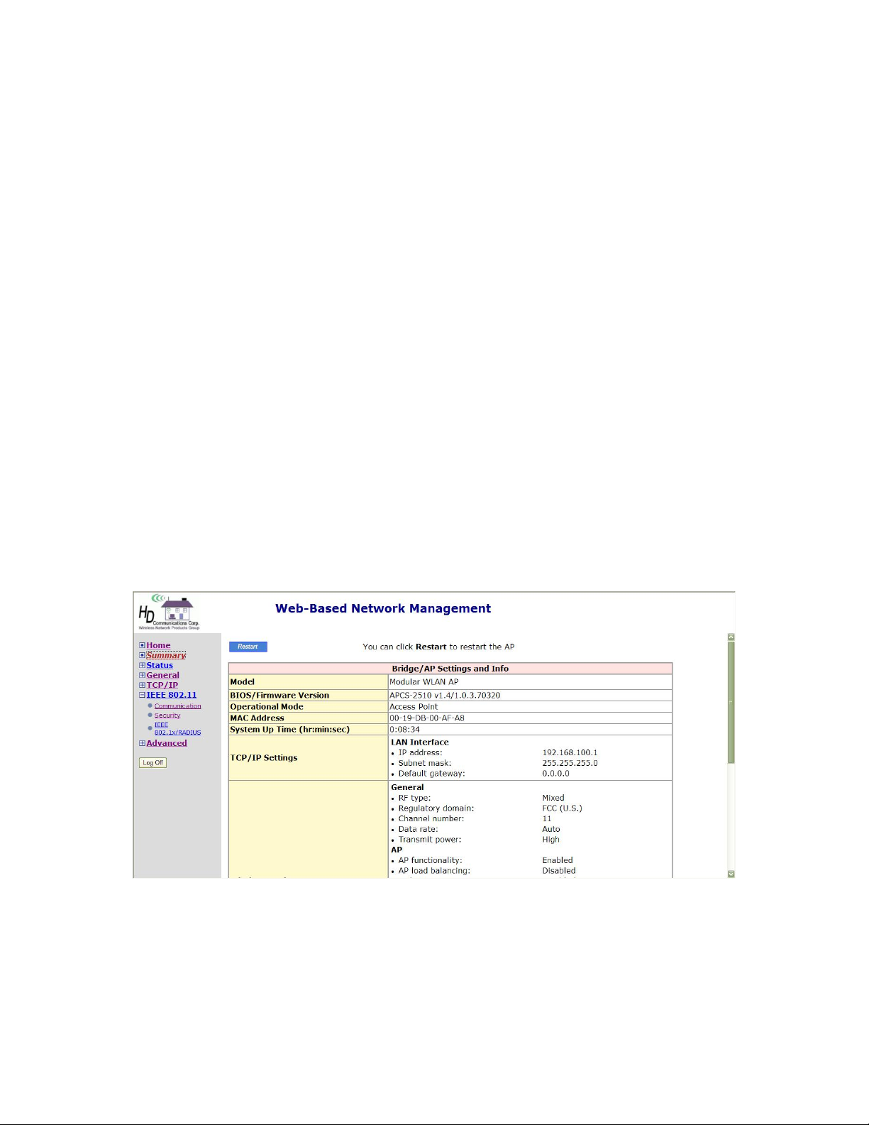
Fig. 8. The Summary page
3.1.1. Menu Structure
The left side of the screen contains a menu for you to carry out commands. Here is a brief description
of the menu options:
12
Page 18

z Home. Click this tab to return to the Home page.
z Summary. Click this tab to view a screen with at-a-glance status information.
z Status. Click this tab to access the following settings:
Wireless Clients. The status of the wireless clients currently associated with the AP.
DHCP Mappings. Current IP-MAC address mappings of the built-in DHCP server.
System Log. System events log.
Link Monitor. When the HD24613 is in AP Client mode, this page shows the signal
strength and link quality of the wireless link to its associated access point.
z General. Click this tab to access the following settings:
Operational Mode. Operational mode of the HD24613 —AP/Bridge or AP Client.
Password. Modify the login settings.
Firmware Tools. For upgrading the firmware of the HD24613, backing up and restoring
configuration, and configuration reset settings of the HD24613.
z TCP/IP. Click this tab to access the following settings:
Addressing. Modify IP address settings of the HD24613.
DHCP Server. Modify settings for the DHCP (Dynamic Host Configuration Protocol)
server.
z IEEE 802.11. Click this tab to access the following settings:
Communication. Modify basic IEEE 802.11b/g settings of the HD24613 to work prop-
erly with wireless clients.
Security. Modify security settings for authenticating wireless users and encrypting wire-
less data.
IEEE 802.1x/RADIUS. Modify IEEE 802.1x Port-Based Network Access Control and
RADIUS (Remote Authentication Dial-In User Service) security settings.
z Advanced. Advanced settings of the HD24613.
Packet Filters. Ethernet Type Filters, IP Protocol Filters, and TCP/UDP Port Filters set-
tings.
Management. Modify UPnP, System Log, and SNMP settings.
3.1.2. Save, Save & Restart, and Cancel Commands
At the bottom of each page that contains settings you can configure, there are up to three buttons—Save, Save & Restart, and Cancel. Clicking Save stores the settings changes to the memory of
the HD24613 and brings you back to the Summary page. Clicking Save & Restart stores the settings
changes to the memory of the HD24613 and restarts the HD24613 immediately for the settings
13
Page 19
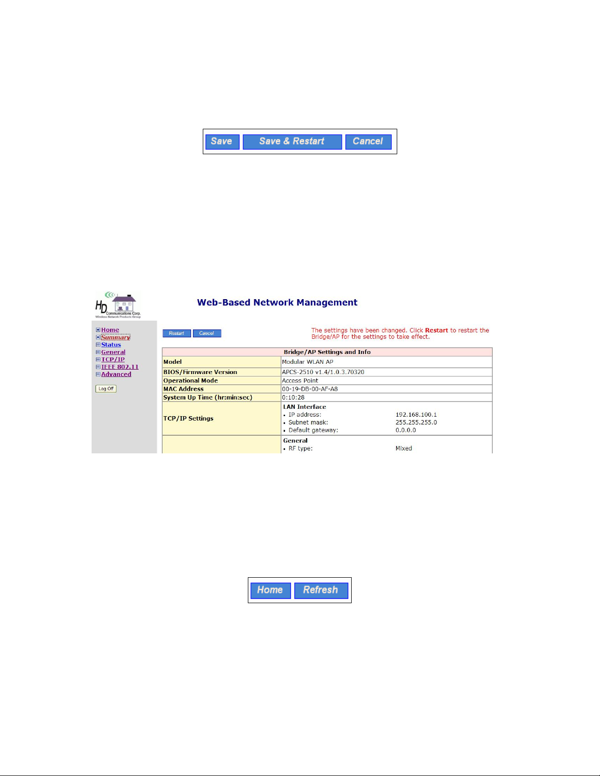
changes to take effect. Clicking Cancel discards any settings changes and brings you back to the start
page.
Fig. 9. Save, Save & Restart, and Cancel.
If you click Save, the start page will reflect the fact that the configuration settings have been changed
by showing t wo buttons— Restart and Cancel. In addition, changes are highlighted in red. Clicking
Cancel discards all the changes. Clicking Restart restarts the HD24613 for the settings changes to
take effect.
Fig. 10. Settings have been changed
3.1.3. Home and Refresh Commands
At the bottom of a status page, there are two buttons—Home and Refresh. Clicking Home brings you
back to the Summary page. Clicking Refresh updates the shown status information.
Fig. 11. Home and Refresh buttons
14
Page 20
3.2. Viewing Status
3.2.1. Associated Wireless Clients
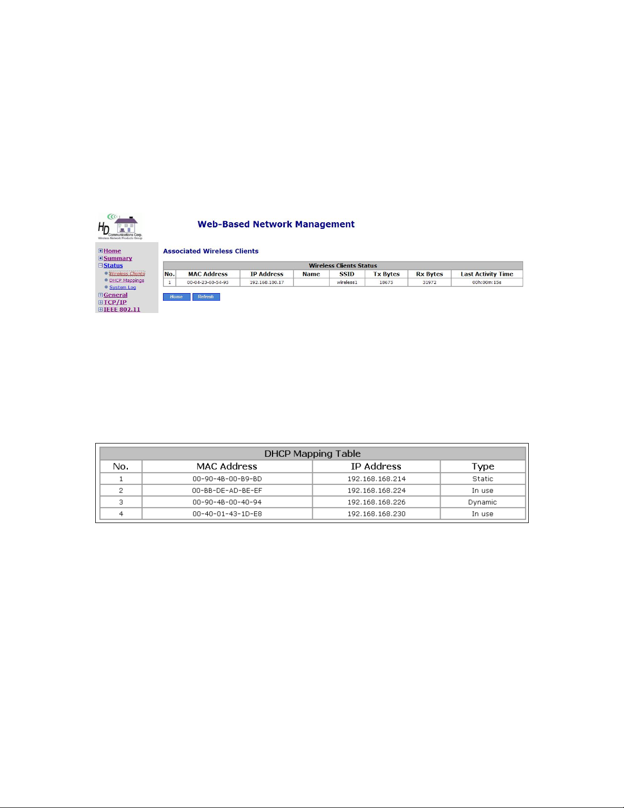
On this page, the status information of each associated client, including its MAC address, IP address,
user name (if the client has been IEEE 802.1x authenticated), number of bytes it has sent, number of
bytes it has received, and the time of its last activity, is shown.
Fig. 12. Status of associated wireless clients
3.2.2. Current DHCP Mappings
On this screen, all the current static or dynamic DHCP mappings are shown. A DHCP mapping is a
correspondence relations hip between an IP address assigned by the DHCP server and a computer or
device that obtains the IP address. A computer or device that acts as a DHCP client is identified by its
MAC address.
Fig. 13. Current DHCP mappings
A static mapping indicates that the DHCP client always obtains the specified IP address from the
DHCP server. You can set static DHCP mappings in the Static DHCP Mappings section of the
DHCP Server configuration page (see Section 3.4.2). A dynamic mapping indicates that the DHCP
server chooses an IP address fro m the IP address pool s pecified by the First al locateable IP address
and Allocateable IP address count settings on the DHCP Server configuration page.
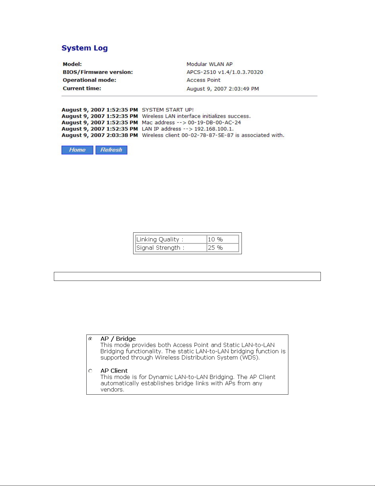
3.2.3. System Log
System events are recorded in the memory of the HD24613. The logged information is useful for
troubleshooting purposes. See Section 3.6.2.2 for more information.
15
Page 21
3.2.4. Link Monitor
Fig. 14. System log
When the HD24613 is in AP Client mode, use the Link Monitor feature to monitor the link quality
and signal strength of the connection. Larger values mean better wireless connectivity to the Access
Point.
Fig. 15. Link monitor
NOTE: The values are updated every 20 seconds.
3.3. General Operations
3.3.1. Specifying Operational Mode
Fig. 16. Operational mode settings
The HD24613 supports two operational modes:
AP/Bridge. This mode provides both Access Point and Static LAN-to-LAN Bridging
functionality. The static LAN-to-LAN bridging function is supported through Wireless
16
Page 22

Distribution System (WDS).
AP Client. This mode is for Dynamic LAN-to-LAN Bridging. The AP Client automati-
cally establishes bridge links with APs from any vendors.
In either mode, the HD24613 forwards packets between its Ethernet interface and wireless interface
for wired hosts on the Ethernet side and wireless host(s) on the wireless side.
There are 2 types of wireless links as specified by the IEEE 802.11 standard.
STA-AP. This type of wireless li nk is establi shed bet ween an IEEE 802.11 Stat ion (STA)
and an IEEE 802.11 Access Point (AP). An STA is usually a client computer (PC or PDA)
with a WLAN network interface card (NIC). The AP Client mode is actually an STA.
WDS. This type of wireless link is established between two IEEE 802.11 HD24613’s.
Wireless packets transmitted along the WDS link comply with the IEEE 802.11 WDS
(Wireless Distribution System) format at the link layer.
The relationships among the operational modes and the wireless link types are shown in the following
table:
AP/Bridge AP Client
AP/Bridge WDS STA-AP
AP Client STA-AP
Table 2. Operational modes vs. wireless link types
To establish a static bridge link based on WDS, the AP/bridges at both end of the WDS link must be
manually configured with each other’s MAC addresses (see Secti on 3. 5.1. 5 for more inf orma tion) . T o
establish a dynamic bridge link between a HD24613 and an AP Client, both devices have to be configured with the same SSID and WEP settings. The AP Client automatically scans for any HD24613
that is using the matched SSID and establishes a bridge link with the scanned HD24613.
NOTE: Although it’s more convenient to use dynamic bridging, it has a limitation—the AP Client
only can forward TCP/IP pac kets between its wireless interface and Ethernet interf ace; other type of
traffic (such as IPX and AppleTalk) is not forwarded.
TIP: When the HD24613 is configured to be in AP Client, it can be used as an Ethernet-to-wireless
network adapter. For example, a notebook computer equipped with an Ethernet adapter can be connected to this device with a crossover Ethernet cable for wireless connectivity to another access point.
17
Page 23
3.3.2. Changing Password
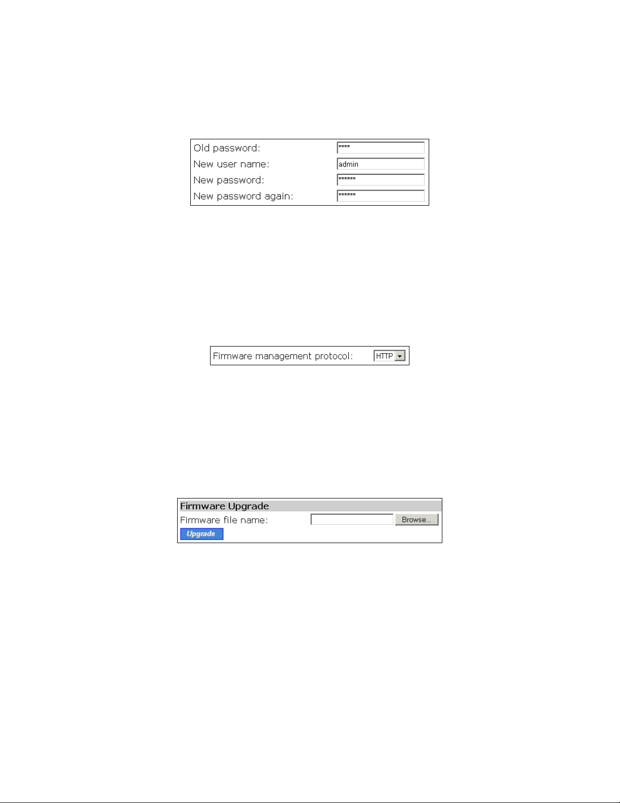
On this screen, the user name and password may be changed. The new password must be typed twice
for confirmation.
Fig. 17. Password
.
3.3.3. Managing Firmware
Firmware management operations for the HD24613 include firmware upgrade, configuration backup,
configuration restore, and configuration reset. Firmware upgrade, configuration backup, and configu-
ration restore can be achieved via HTTP or TFTP.
Fig. 18. Firmware management protocol setting
The HTTP method is suggested since it is more user friendly. However, due to different behavior of
various Web browsers, HTTP-based firmware management operations may not work properly with
some Web browsers. If you cannot successfully perform HTTP-based firmware management operations with your Web browser, try the TFTP-method.
3.3.3.1. Upgrading Firmware by HTTP
Fig. 19. Firmware upgrade by HTTP
To upgrade firmware of the HD24613 by HTTP:
1. Click Browse and then select a correct firmware .bin file. The fir mware file path will be shown
in the Firmware file name text box.
2. Click Upgrade to begin the upgrade process.
18
Page 24
3.3.3.2. Backing up and Restoring Configuration Settings by HTTP
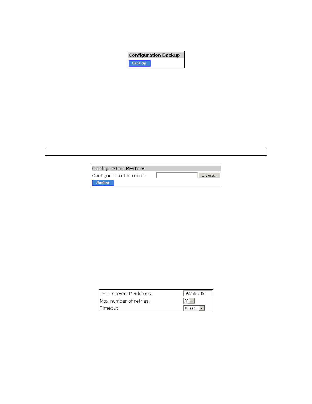
Fig. 20. Firmware backup by HTTP
To back up configuration of the HD24613 by HTTP:
1. Click Back Up.
2. You’ll be prompted to open or save the configuration file. Click Save.
3. The configuration file is named by the HD24613’s MAC address. For example, if the
HD24613’s MAC address is 00-01-02-33-44-55, the configuration backup file should be
“000102334455.hex”. Don’t change the configuration file name in the Save As dialog box. Select a folder in which the configuration file is to be stored. And then, click Save.
NOTE: The procedure may be a little different with different Web browsers.
Fig. 21. Configuration restore by HTTP
To restore configuration of the HD24613 by HTTP:
1. Click Browse and then select a correct confi guration .hex file. You have to make sure the file
name is the AP’s MAC address. The firmware file path will be shown in the Firmware file
name text box.
2. Click Restore to upload the configuration file to the HD24613
3.3.3.3. Upgrading Firmware by TFTP
To configure settings for the HD24613’s TFTP client to communicate with a TFTP server, select
TFTP as the firmware management protocol.
Fig. 22. TFTP server settings.
. If the TFTP client does not get a re sponse from the TFTP server within a period specified by the
Timeout setting, it will resend the previous request. The Max number of retries setting specifies the
maximal number of resend before the TFTP client stops communicating with the TFTP server.
19
Page 25
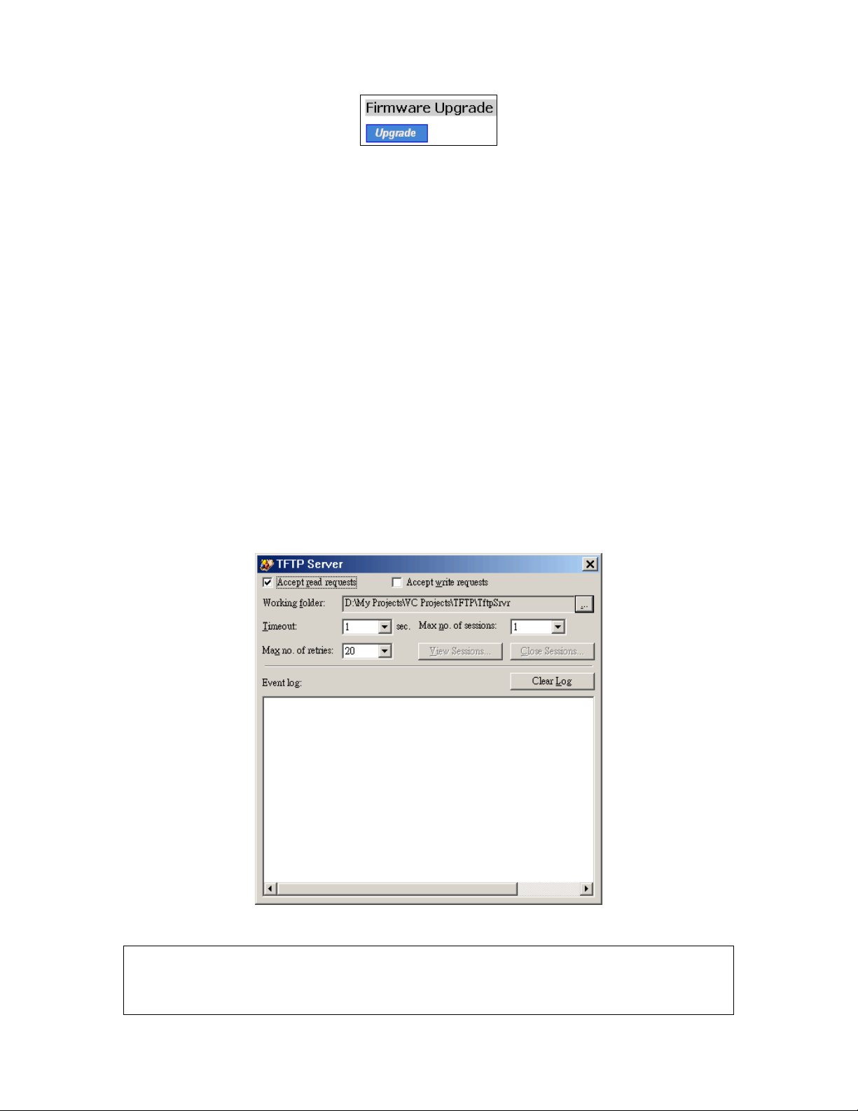
Fig. 23. Firmware upgrade by TFTP
To upgrade firmware of the HD24613 by TFTP:
1. Get a computer that will be used as a TFTP server and as a managing computer to trigger the
upgrade process .
2. Connect the computer and one of the LAN Ethernet switch port with a normal Ethernet cable.
3. Configure IP address of the comput er so that the HD24613 and t he computer are in the s ame IP
subnet.
4. On the computer, run the TFTP Server utility. And specify the folder in which the firmware files
reside.
5. On the computer, run a Web browser and click the General, Firmware Tools hyperlink.
6. Choose TFTP as the Firmware management protocol.
7. Specify the IP address of the computer, whic h acts as a TFTP server. If you don’t know the IP
address of the computer, open a Command Prompt, and type IpConfig, then press the Enter key.
8. Trigger the firmware upgrade process by clicking Upgrade.
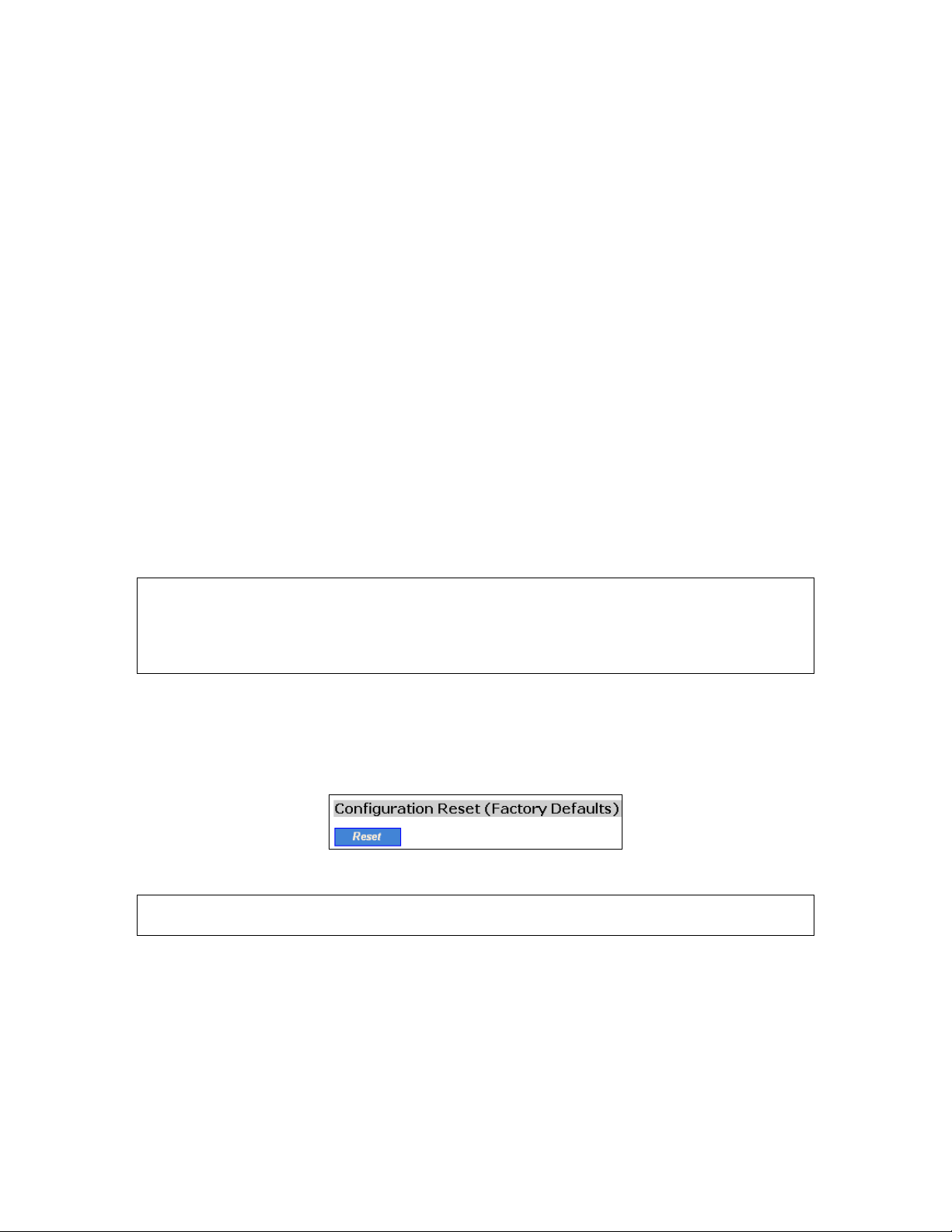
Fig. 24. TFTP Server.
NOTE: After the dialog box of the TFTP server program appears, be sure to specify the working
folder within which the downloaded firmware files reside.
NOTE: Make sure the Accept read requests check box of TFTP Server is selected.
20
Page 26

NOTE: The L AN IP address of the HD24613 and the IP ad dress of the TFTP server must be in the
same IP subnet for TFTP to work.
NOTE: Due to the unreliable natur e of w ir eless media, it’s hig hly r eco mmende d that t he TFTP serve r
and the to-be-upgraded wireless HD24613 be connected by Ethern et, and on the same LAN, so that
the upgrade process would be smooth.
NOTE: After the firmware is upgraded, be sure to delete the contents of the Web browser cache, so
that the Web management pages can be shown correctly.
NOTE: A failed upgrade may corrupt the firmware and make the HD24613 unbootable. When this
occurs, call for technical support.
TIP: If you want to remotely upgrade the firmware of a deployed HD24613 from the Internet, adjust
the Timeout and Max no. of retries settings of TFTP Server for remote TFTP upgrade to succeed.
3.3.3.4. Backing up and Restoring Configuration Settings by TFTP
Fig. 25. Configuration backup/restore
To back up configuration of the HD24613 by TFTP:
1. Get a computer that will be used as a TFTP server and as a managing computer to trigger the
backup process.
2. Connect the computer and one of the LAN Ethernet switch port with a normal Ethernet cable.
3. Configure the IP address of the computer so that the c omputer a nd the HD246 13 are in the sa me
IP subnet.
4. On the computer, run the TFTP Server utility. Select the Accept write requests check box, and
specify the folder to which the configuration settings of the HD24613 will be saved.
5. On the computer, run a Web browser and click the General, Firmware Tools hyperlink.
6. Choose TFTP as the Firmware management protocol.
7. Within the Configuration Backup/Restore section, specify the IP address of the computer,
which acts as a TFTP server. If you don’t know the IP address of the co mputer, open a Command Prompt, and type IpConfig, then press the Enter key.
8. Trigger the backup process by clicking Back Up. The HD24613’s configuration settings will be
saved as “AaBbCcDdEeFf.hex” by the TFTP server, where “AaBbCcDdEeFf” is the AP’s
MAC address. For example, if the AP’s MAC address is 00-01-02-33-44-55, the configurati on
backup file will be “000102334455.hex”.
NOTE: Remember to select the Accept write requests check b ox of TFTP Server.
21
Page 27
To restore configuration of the HD24613 by TFTP:
1. Get a computer that will be used as a TFTP server and as a managing computer to trigger the
restoring process.
2. Connect the computer and one of the LAN Ethernet switch port with a normal Ethernet cable.
3. Configure the IP address of the computer so that the c omputer a nd the HD246 13 are in the sa me
IP subnet.
4. On the computer, run the TFTP Server utility. And specify the folder in which the configuration
backup file resides. A configuration backup file is named by the AP’s MAC address. For example, if the AP’s MAC address is 00-01-02-33-44-55, the configuration backup file should be
“000102334455.hex”.
5. On the computer, run a Web browser and click the General, Firmware Tools hyperlink.
6. Choose TFTP as the Firmware management protocol.
7. Within the Configuration Backup/Restore section, specify the IP address of the computer,
which acts as a TFTP server. If you don’t know the IP address of the co mputer, open a Command Prompt, and type IpConfig, then press the Enter key.
8. Trigger the restoring process by clicking Restore. The HD24613 will then download the confi-
guration backup file from the TFTP server.
NOTE: Make sure the file is a valid configuration backup file for the HD24613.
TIP: If you want to remotely back up or restore configuration from the Internet, adjust the Timeout
and Max no. of retries settings of TFTP Server for remote TFTP configuration backup/restore to
succeed.
3.3.3.5. Resetting Configuration to Factory Defaults
Clicking the Reset button resets the device configuration to factory defaults.
Fig. 26. Configuration reset
WARNING: Think twice before using the Reset button, as all your current configuration settings will
be removed.
3.4. Configuring TCP/IP Related Settings
3.4.1. Addressing
The IP address of the HD24613 can be manually set (Set Manually) or automatically assigned by a
DHCP server on the LAN (Obtain from a DHCP Server). If you are manually setting the IP ad-
dress, Subnet mask, and Default gateway settings, set them appropriately, so that they comply with
22
Page 28
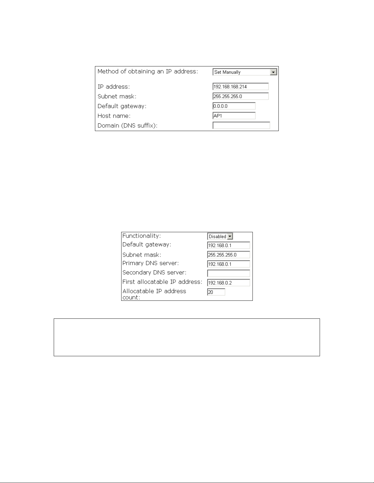
your LAN environment. In addition, you can specify the Host name and Domain (DNS suffix) of the
HD24613.
Fig. 27. TCP/IP settings
3.4.2. DHCP Server
3.4.2.1. Basic
The HD24613 can automatically assign IP addresses to client computers by DHCP. From this
screen, you can specify the Default gateway, Subnet mask , Primary DNS server, and Secondary
DNS server settings that will be sent to a client at its request. Additionally, you can specify the first
IP address that will be assigned to the clients and the number of IP addresses available for allocation.
Fig. 28. Basic DHCP server settings.
NOTE: There should be only one DHCP server on the LAN; otherwise, DHCP would not work prop-
erly. If there is already a DHCP server on the LAN, disable the DHCP server functionality of the
HD24613.
NOTE: By default the DHCP server function is disabled.
3.4.2.2. Static DHCP Mappings
IP addresses of servers are often static so that clients could alw ays locate the servers by the static IP
addresses. By Static DHCP Mappings, you can ensure that a host will get the same IP address when
it requests one from the DHCP server. Therefor e, instead of configuring the IP address of an intranet
server manually, you can configure the server to obtain an IP address by DHCP and it is always assigned the same IP address.
23
Page 29
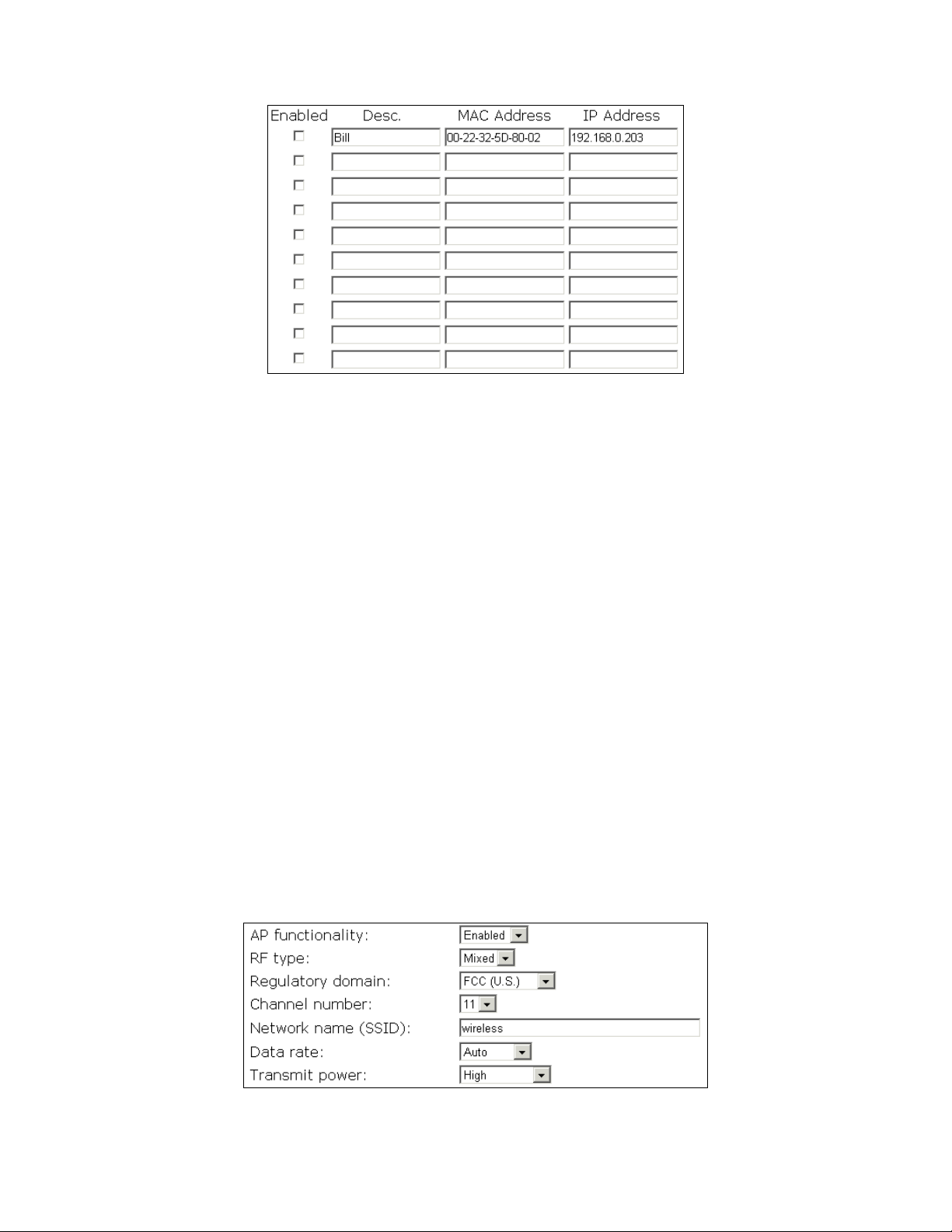
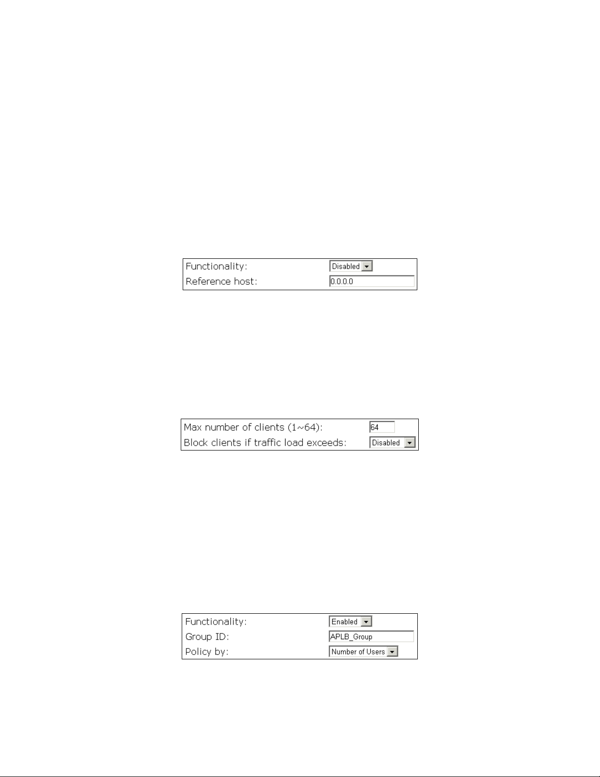
Fig. 29. Static DHCP mappings
To always assign a static IP address to a specific DHCP client:
1. Specify the MAC address of the DHCP c lient and th e IP address to be assigned to it. Then, gi ve
a description for this mapping.
2. Select the corresponding Enabled check box.
3.5. Configuring IEEE 802.11 Related Settings
3.5.1. Communication
3.5.1.1. Basic
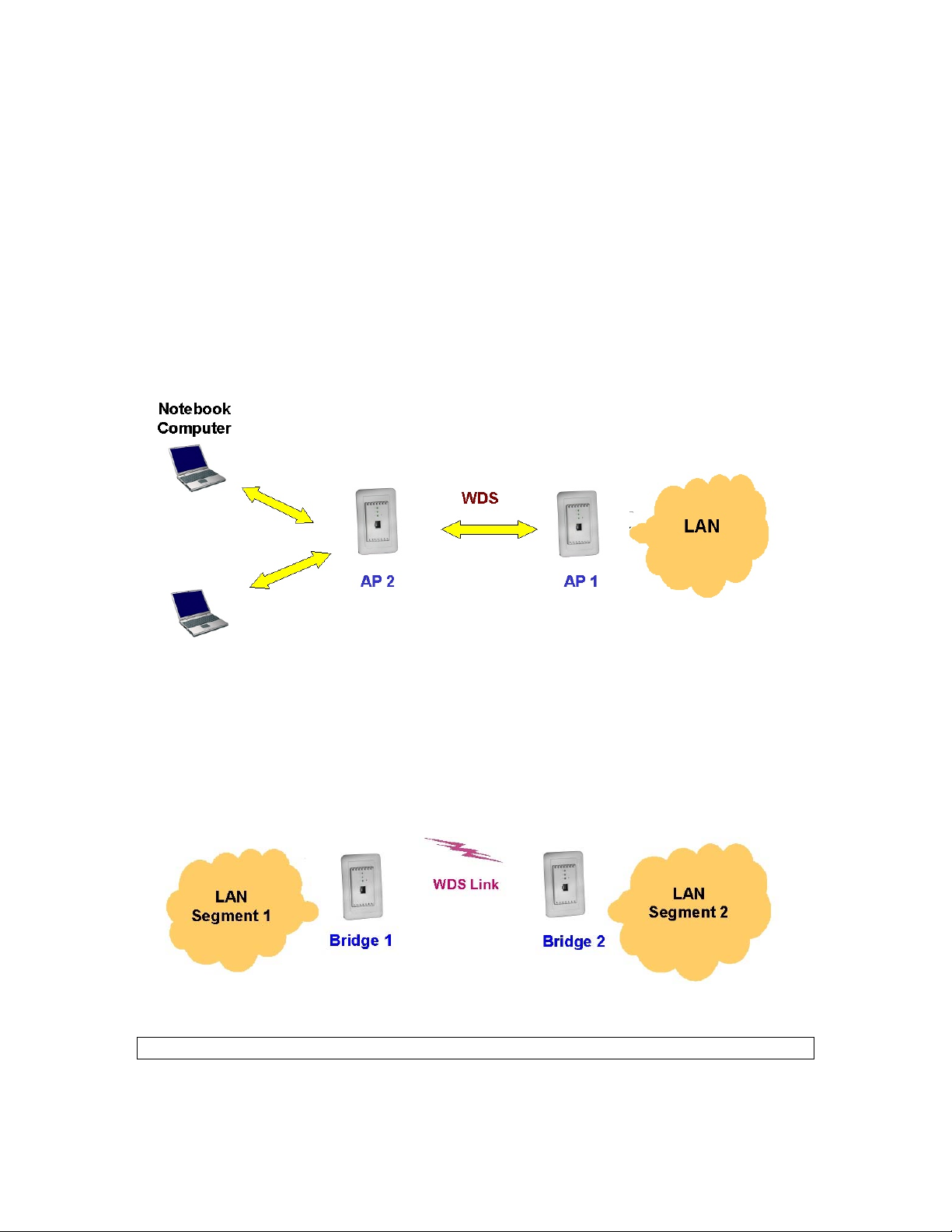
Basic IEEE 802.11g-related communication settings include HD2461 3 function ality, RF type, Regulatory domain, Channel number, Multiple Network name (SSID), Data rate, and Transmit
power.
For specific needs such as configuring the HD24613 as a wireless LAN-to-LAN bridge, the HD24613
functionality can be disabled, so that no wireless client can associate with the HD24613.
Fig. 30. Basic IEEE 802.11g communication settings
24
Page 30
The RF type of the WLAN interface can be configured to work in IEEE 802.11b only (b Only), IEEE
802.11g only (g Only), or mixed mode (Mixed—802.11g and 802.11b simultaneously).
The number of available RF channels depends on local regulations; therefore you have to choose an
appropriate regulatory domain to comply with local regulations. The SSID of a wireless client computer and the SSID of the HD24613 must be identical for them to communicate with each other.
If there is RF interference, you may want to reduce the Data rate for more reliable wireless transmission. In most cases, leave the setting to Auto.
The transmit power of the RF module of the HD2 4613 can be adj usted so that the RF covera ge of the
HD24613 can be changed.
3.5.1.2. Link Integrity
Fig. 31. Link integrity settings
When the Ethernet LAN interface is detected to be disconnected from the wired network, all currently
associated wireless clients are disassociated by the HD24613 and no wireless client can associate with
the HD24613. The detection mechanism is based on pinging the IP address specified in Reference
host.
3.5.1.3. Association Control
Fig. 32. Association control settings
If the number of currently associated wireless client s exceeds the value specified in the Max number
of clients setting, no more wireless client can associate with the HD24613. If traffic load of the
HD24613 exceeds the load specified in the Block clients if traffic load exceeds setting, no more
wireless client can associate with the HD24613.
3.5.1.4. Load Balancing
Several HD24613’s can form a load-balancing group if they are set with the same Group ID. The
load-balancing policy can be by Number of Users or by Traffic Load.
Fig. 33. HD24613 load balancing settings
25
Page 31
If the by-number-of-users policy is selected, a new wireless user can only a ssociate with an HD2461 3
that has the smallest number of associated wireless users in the group. On the other hand, if the
by-traffic-load policy is selected, a new wireless user can only associate with an HD24613 that has th e
less traffic load in the group.
3.5.1.5. Wireless Distribution System
Traditionally, access points are connected by Ethernet. By Wireless Distrib ution Syste m (WDS), APs
can communicate with one another wirelessly . For example, in Fig. 34, AP 2 acts as an access point
for the notebook computers and it forwards packets sent from the notebook computers to AP 1
through WDS. Then, AP 1 for wards the packets to the Et hernet LAN. Packets destin ed for the notebook computers follow a rever se path from the Ethernet L AN through the APs to the notebook computers. In this way, AP 2 plays a role of “AP repeater”.
Fig. 34. Wireless Distribution System
By WDS, two or more LAN segments can be connected wirelessly. As illustrated in Fig. 35, a pair of
wireless LAN-to-LAN bridges is used to connect two LAN segments. Since the HD24613 is
WDS-enabled, it can be used as a wireless bridge.
Fig. 35. LAN-to-LAN bridging
NOTE: A HD24613 can have up to 6 WDS links to other APs or wireless bridges.
26
Page 32
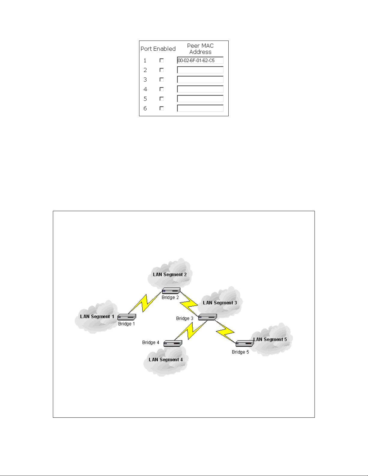
Fig. 36. Wireless Distribution System settings
To enable a WDS link:
1. Specify the MAC address of the HD24613 at the other end of the WDS link.
2. Select the corresponding Enabled check box.
For example, assume you want two HD24613’s with MAC addresses 00-02-65-01-62-C5 and
00-02-65-01-62-C6 to establish a WDS link between them. On HD24613 00-02-65-01-62-C5, set the
peer MAC address of port 1 to 00-02-65-01-62-C6 and on AP 00-02-65-01-62-C6, set the peer MAC
address of port 1 to 0 0 -02-65-01-C5.
TIP: Plan your wireless network and draw a diagra m, so that y ou know how a HD24613 i s conn ected
to other peer HD24613 s or wireless bridges by WDS.
TIP: Plan your wireless network and draw a diagram, so that you know how a bridge is connected to
other peer bridges by WDS. See the following figure for an example network-planning diagram.
Fig. 37. Sample wireless bridge network topology.
WARNING: Don’t let your network topology consisting of wireless bridges, Ethernet switches,
Ethernet links, and WDS links contain loops. If any loops exist, packets will circle around the loops
and network performance will be seriously degraded.
27
Page 33
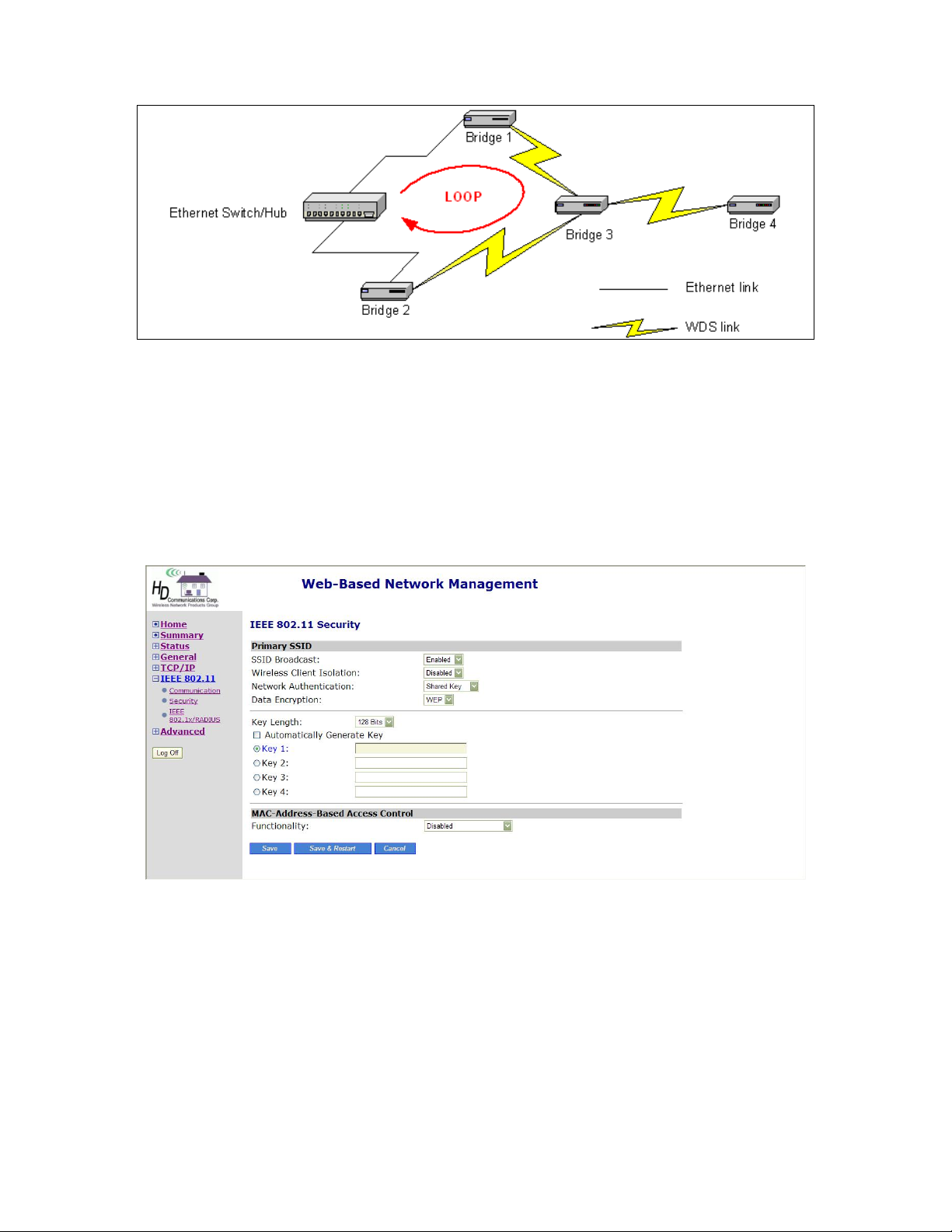
Fig. 38. Network topology containi n g a l o op
If external high-gain directional antennas are used, it’s difficult to align the antennas when the distance between the bridges is long.
3.5.2. Security
IEEE 802.11g security settings include SSID broadcasts, Wireless client isolation, Security mode,
IEEE 802.11 Authentication algorithm, WEP keys, MAC-Address-Based Access Control.
TABLE OF SECURITY SETTING DEFINITIONS
SSID The network name
SSID Broadcasts Enable or Disable SSID broadcast.
Enabling this feature broadcasts the SSID across the netw or k.
Wireless Client
Isolation
When the HD24613 is in AP/Bridge mode, wireless-to-wireless traffic can be blocked so
that the wireless clients cannot see each other. This capability can be used in hotspots applications to prevent wireless hackers from attacking other wireless users’ computers.
28
Page 34
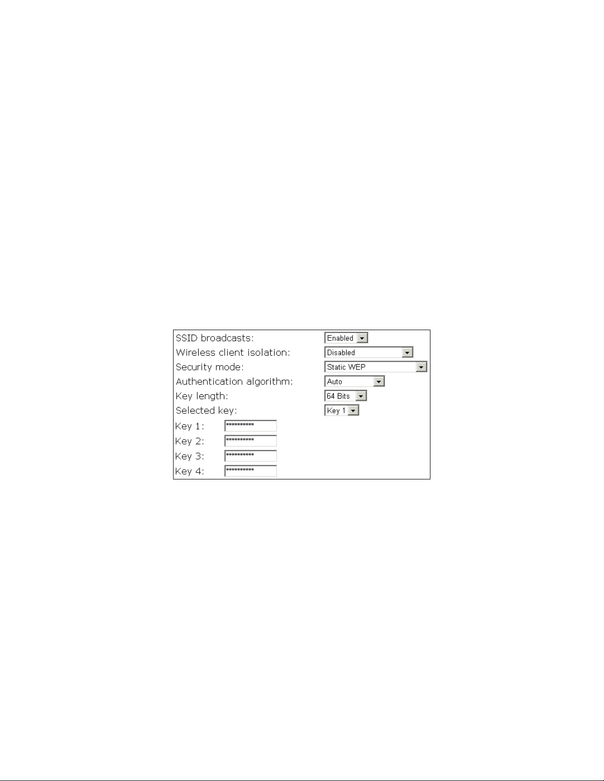
Security mode The Security options for the primary SSID (SSID1) are up to 9 security modes
depending on AP mo del variations :
Open System. No authentication, no data encryption.
Static WEP. WEP (Wired Equivalent Privacy) keys must be manually configured.
Key Length
Selected Key Select the 1st through the 4th key to be the active key. Enter the key that you need here.
Select 64-, 128-bits
3.5.2.1. Selecting Wireless Security Mode
For security reasons, it’s highly recommended that the security mode be set to options other than
Open System. When the security mode is set to Open System, no authentication and data encryption
will be performed. Additionally, you can disable t he SSID broad casts functionality so that a wireless
client computer with an “any” SSID cannot associate with the AP.
Fig. 38. Basic IEEE 802.11g security settings
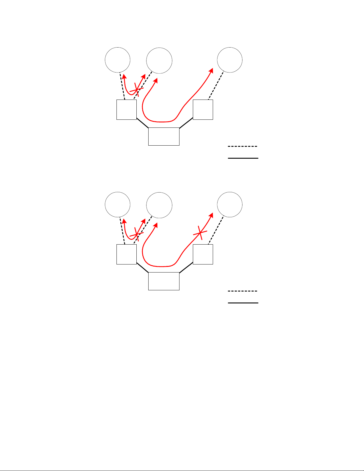
When the Wireless client isolation setting is set to This AP Only, wireless clients of this HD24613
cannot see each other, and wireless-to-wireless traffic is blocked. When the setting is set to All APs in
This Subnet, traffic among wireless users of different HD24613’s in the same IP subnet is blocked.
This feature is useful for WLANs deployed in public places. In this way, hackers have no chance to
attack other wireless users in a hotspot.
When the Wireless client isolation setting is set to This AP Only, wireless clients (STAs) of this
HD24613 cannot see each other, and wireless-to-wireless traffic between the STAs is blocked. When
the setting is set to All APs in This Subnet, traffic among wireless users of different HD24613’s in
the same IP subnet is blocked. The behaviors are illustrated in the followin g figures.
29
Page 35
STA 1
STA 2
STA 3
AP 1 AP 2
WCI:
This AP Only
WCI:
This AP Only
Switch
Wireless Link
Ethernet Link
Fig. 39. Behavior of the “This AP Only” wireless client isolation option
STA 1
STA 2
STA 3
AP 1 AP 2
WCI:
All APs in This
Subnet
Switch
WCI:
All APs in This
Subnet
Wireless Link
Ethernet Link
Fig. 40. Behavior of the “All APs on This Subnet” wireless client isolation option
As illustrated in Fig. 39 when AP 1 and AP 2 are using the “This AP Only” option, wireless traffic
between STA 1 and STA 2 is blocked by AP 1, while wireless t raffic between STA 2 and STA 3,
which are associated with different APs, is still allowed. If the “All APs in This Subnet” option is
used as shown in Fig. 4 0, AP 1 and AP 2 communicat es with each other via an inter-AP protocol to
share their STA association information to block wireless traffic among all the STAs.
Choose from up to 7 security modes:
z Open System. No authentication, no data encryption.
z Static WEP. WEP (Wired Equivalent Privacy) keys must be manually configured.
z Static TKIP (WPA-PSK). Only TKIP (Temporal Key Integrity Protocol) mechanism of WPA
(Wi-Fi Protected Access) is enabled. In this mode, you have to specify the Pre-shared key,
30
Page 36

which will be used by the TKIP engine as a master key to generate keys that actually encrypt
outgoing packets and decrypt incoming packets.
NOTE: The Pre-Shared Key has a minimum of 8 and maximum of 63 characters.
z IEEE 802.1x EAP without Encryption (EAP-MD5). The IEEE 802.1x functionality is
enabled and the user-name/password-based EAP-MD5 authentication is used. No data encryption.
z IEEE 802.1x EAP with Static WEP (EAP-MD5). The IEEE 802.1x functionality is enabled
and the user-name/password-based EAP-MD5 authentication is used. Data encryption is
achieved by static WEP.
z IEEE 802.1x EAP with Dynamic WEP (EAP-TLS, EAP-TTLS, PEAP). The IEEE 802. 1x
functionality is enabled and dynamic WEP key distribution authentication (EAP-TLS,
EAP-TTLS, or PEAP) is used. Data encryption is achieved by dynamic WEP.
z IEEE 802.1x EAP with Dynamic TKIP (WPA). This is a full WPA mode, in which both the
TKIP and IEEE 802.1x dynamic key exchange mechanisms are enabled. The HD24613 is highly
secured in this mode.
In the above security modes, a back-end RADIUS (Remote Authentication Dial-In User Service)
server is needed if IEEE 802.1x functionality is enabled. See Section 3.5.3 for more information about
IEEE 802.1x and RADIUS.
According to the IEEE 802.11 standard, WEP can be used for authentication and data encryption.
Normally, Shared Key authentication is used if WEP data encryption is enabled. In rare cases, Open
System authentication may be used whe n WEP data encryption is enabled. The Authenticati on algo-
rithm setting is provided for better compatibility with wireless clients with various WLAN network
adapters. There are three options available, including Open System, Shared Key, and Auto.
When WEP is ena ble d by a securi ty mode , the Key len gth can be specified to be 64 Bits or 128 Bits.
The Sele cted key setting specifies the key to be used as a send-key for encrypting traffic from the
HD24613 side to the wireless client side. All 4 WEP keys are used as receive-keys to decry pt traffic
from the wireless client side to the HD24613 side.
NOTE: Each field of a WEP key setting is a hex-decimal number f rom 00 to FF. For example, when
the security mode is Static WEP and the key length is 64 Bits, you could set Key 1 to
“00012E3ADF”.
3.5.2.2. MAC-Address-Based Access Control
When the MAC-Address-Based Access Control feature, the wir eless client computers that are permitted or not permitted to associate with the HD24613 can specified. Whe n the table type is set to
inclusive, entries in the table are permitted to associat e with the HD24613. When the table type is set
to exclusive, entries in the table are not permitted to associate with the HD24613.
31
Page 37
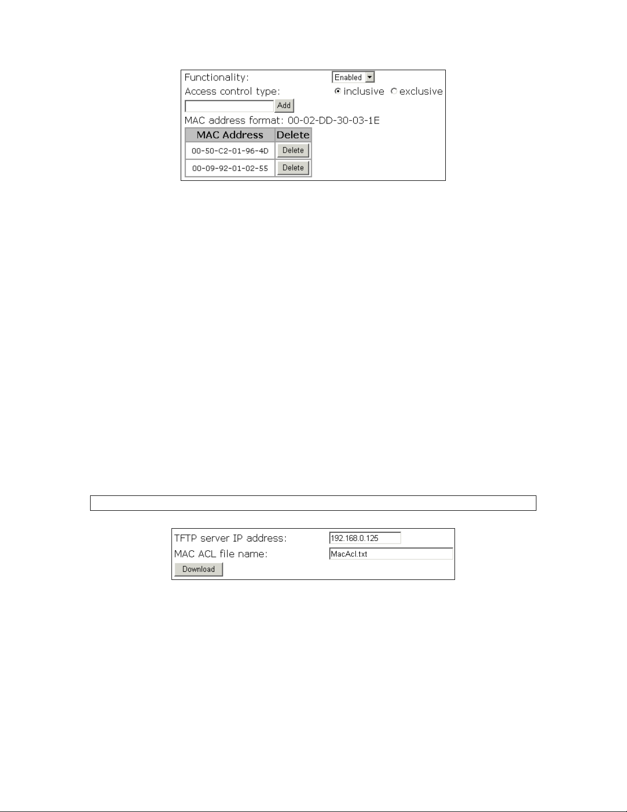
Fig. 41. MAC-address-based access control settings
To deny wireless clients’ access to the wireless network:
1. Select Enabled from the Functionality drop-down lis t.
2. Set the Access control type to exclusive.
3. Specify the MAC address of a wireless client to be denied access, and then click Add.
4. Repeat Steps 3 for other wireless clients.
To grant wireless clients’ access to the wireless network:
1. Select Enabled from the Functionality drop-down lis t.
2. Set the Access control type to inclusive.
3. Specify the MAC address of a wireless client to be denied access, and then click Add.
4. Repeat Steps 3 for other wireless clients.
To delete an entry in the access control table:
z Click Delete next to the entry.
NOTE: The size of the access control table is 64.
Fig. 42. MAC ACL do wnload settings
Instead of manually entering MAC addresses to the access contr ol table one by one , y ou can prepa re a
text file that contains all the MAC addresses and put it on a TFTP server, and then command the
HD24613 to download the MAC ACL (Access Control List) file from the TFTP server. Fig. 43 shows
the contents of a sample ACL file.
32
Page 38

Fig. 43. Sample MAC ACL file
To download a MAC ACL file from a TFTP server:
1. Specify the IP address of the TFTP server in the TFTP server IP address text box.
2. Specify the name of the MAC ACL file on the TFTP server in the MAC ACL file name text
box.
3. Click Download.
3.5.3. IEEE 802.1x/RADIUS
IEEE 802.1x Port-Based Network Access Control is a new standard for solving some security issues
associated with IEEE 802.11, such as lack of user-based authentication and dynamic encryption key
distribution. With IEEE 802.1x and the help of a RADIUS (Remote Authentication Dial-In User Service) server and a user account database, an enterpri se or ISP (Internet Service Provider) can manage
its mobile users’ access to its wireless LANs. B efore granted access to a wireless LAN supporting
IEEE 802.1x, a user has to issue his or her us er nam e and password or digital certificate to the backend RADIUS server by EAPOL (Extensible Authentication Pr otocol Over LAN). The R ADIUS server can record accounting information s uch as when a user logs on to the wireless LAN and logs off
from the wireless LAN for monitoring or billing purposes.
The IEEE 802.1x functionality of the access point is controlled by the security mode (see Section Er-
ror! Reference source not found.). So far, the wireless access point supports two authentication mechanisms—EAP-MD5 (Message Digest version 5), EAP-TLS (Transport Layer Security). If
EAP-MD5 is used, the user has to give his or her user name and password for authentication. If
EAP-TLS is used, the wireless client computer automatically gives the user’s digital certificate that is
stored in the computer har d disk or a smart card f or authentication. And afte r a successful EAP-TLS
authentication, a session key is automatically generated for wireless pack ets encryption between the
wireless client computer and its associated wireless access point. To sum up, EAP-MD5 supports only
user authentication, while EAP-TLS supports user authentication as well as dynamic encryption key
distribution.
33
Page 39
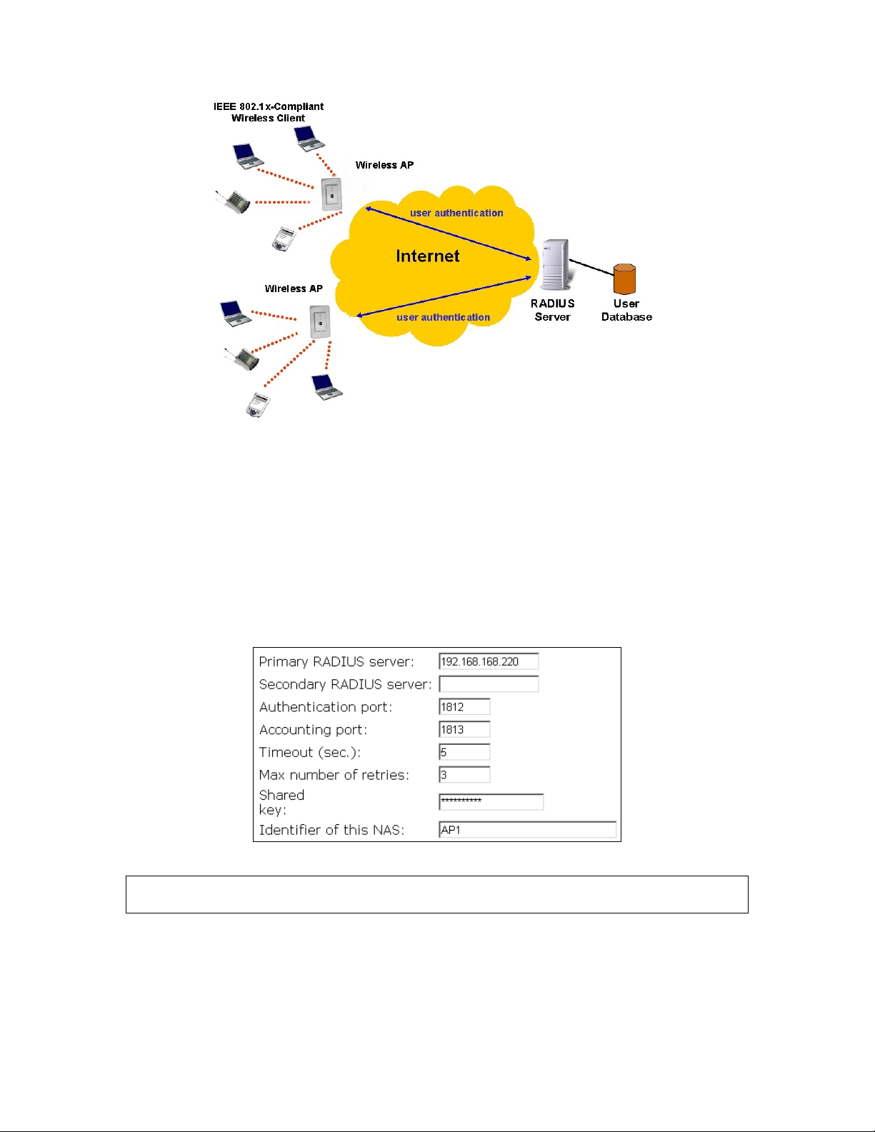
Fig. 44. How IEEE 802.1x and RADIUS works
An access point supporting IEEE 802.1x can be configured to communicate with two RADIUS servers. When the primary RADIUS server fails to respond, the wireless access point will try to communicate with the secondary RADIUS server. You can specify the length of timeout and the number of
retries before communicating with the secondary RADIUS server after failing to communicate with
the primary RADIUS server.
An IEEE 802.1x-capable wireless acce ss point and its RADIUS server(s) share a secret key so that
they can authenticate each other. In addition to its IP address, a wireless access point can identify itself by an NAS (Network Access Server) identifier. Each IEEE 802. 1x-capable wireless access point
must have a unique NAS identifier.
Fig. 45. IEEE 802.1x/RADIUS settings.
TIP: Refer to the IEEE 802.1x-related white papers on the companion CD-ROM for more informati on
about deploying secure WLANs with IEEE 802.1x support.
34
Page 40

3.6. Advanced Settings
3.6.1. Packet Filters
The HD24613 Web-Based Network Management provides layer 2 (Ethernet Type Filters), layer 3 (IP
Protocol Filters), and layer 4 (TCP/UDP Port Filters) filtering capabilities. The configuration
processes for the filters are similar.
Functionality: Sets the filtering as enabled or disabled.
Policy for matched packets: Choose to discard or to pass a matched packet.
To enable a filtering rule: Select the check box to the left of the rule to enable.
3.6.1.1. Ethernet Type Filters
When this feature is enabled, t he Ethernet type field of the MAC (Media Ac cess Control) header of a
packet incoming from the WLAN or Ethernet interface is inspected for filtering. To set a rule, specify
the hex-decimal Ethernet type numbe r and give the rule a name.
Fig. 46. Ethernet type filters settings
3.6.1.2. IP Protocol Filters
When this feature is enabled, the protocol, source address, and destination address fields of a packet
incoming from the WLAN or Ethernet interface is inspected for filtering. To set a rule, specify the
hex-decimal protocol number, source IP address range (Source IP Address AND Source Subnet
Mask), and destination IP address range (Destination IP Address AND Destination Subnet Mask).
35
Page 41
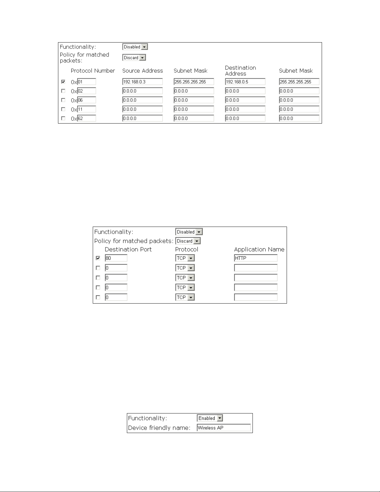
Fig. 47. IP protocol filters settings
A source (destination) IP address range is determined by performing an AND operation on the source
(destination) IP address field and the source (destination) subnet mask field. For example, if the
source IP address field is 192.168.0.1 and the source subnet mask field i s 255.255.255.0, t he resultant
source IP address range is 192.168.0.0 to 192.168.0.255.
3.6.1.3. TCP/UDP Port Filters
The destination port field the TCP or UDP header of a packet incoming from the WLAN or Ethernet
interface is inspected for filtering.
Fig. 48. TCP/UDP port filters settings
To set a rule, specify the decimal Destination Port, Protocol ty pe (TCP/UDP), and the name of the
higher-level protocol (Application Name).
3.6.2. Management
3.6.2.1. UPnP
The UPnP (Universal Plug and Play) features enables a Windows XP user to automatically discover
peripheral devices by HTTP.
Fig. 49. UPnP settings
36
Page 42

When the UPnP functionality is enabled, you can see the HD24613 in My Ne twork Places of Windows XP. The HD24613 can be given a friendly name that will be shown in My Network Places.
Double-clicking the HD24613 icon in My Network Places will launch the default Web browser for
you to configure the AP.
3.6.2.2. System Log
System events can be logged to the on-board RAM of the HD24613 (Local log) or sent to a remote
computer on which an SNMP trap monitor program runs (Remote log by SNMP trap). See the next
subsection for more information about SNMP trap settings.
Fig. 50. System log settings
The system events are divided into the following categories:
General: System and network connectivity status changes.
Built-in AP: Wireless client association and WEP authentication status changes.
MIB II traps: Cold Start, Warm Start, Link Up, Link Down and SNMP Authentication
Failure.
RADIUS user authentication: RADIUS user authentication status changes.
NOTE: The SNMP Authentication Failure trap is issued when using an incorrect community string to
manage the HD24613 via SNMP and the SNMP MIB II OID, snmpEnableAuthenTraps, is enabled
(disabled by default) .
3.6.2.3. SNMP
The SNMP (Simple Network Management Protocol) functionality can be disabled, and you can specify the name (used as a password) of the read-only and read-write community. In addition, up to 5
SNMP trap targets can be set in the SNMP Trap Table.
37
Page 43
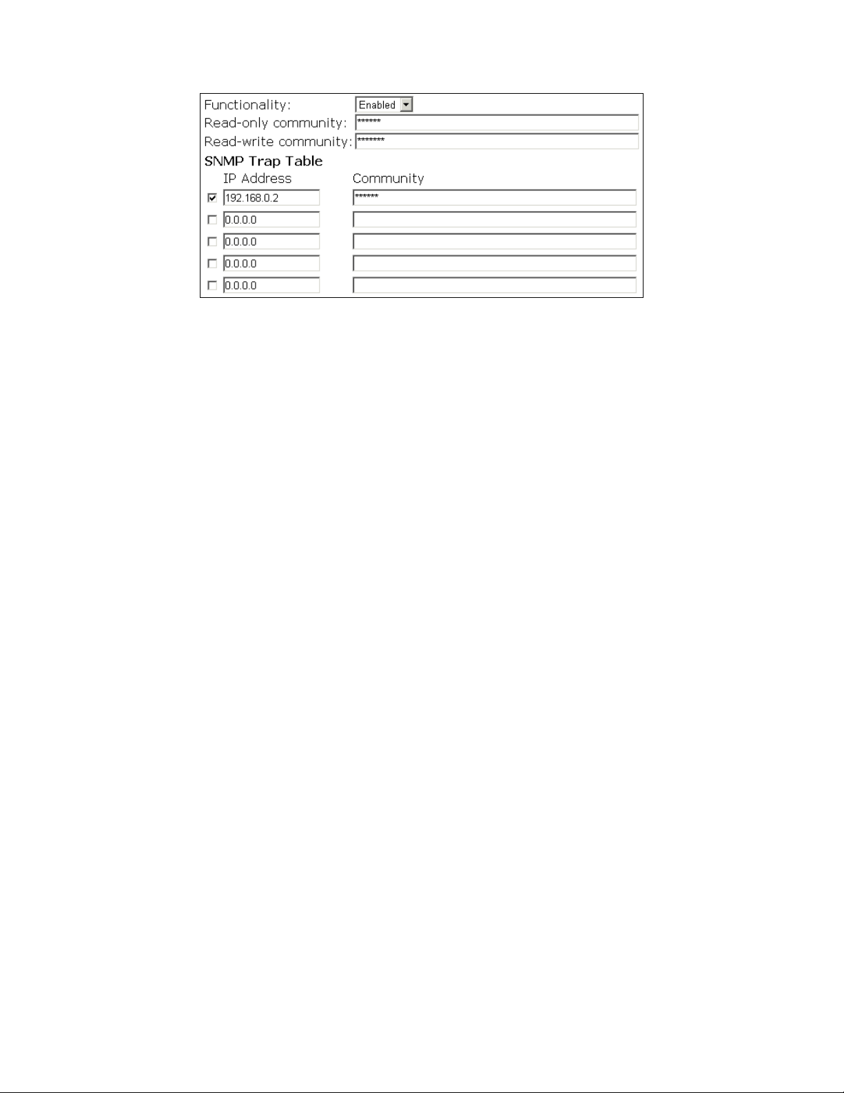
Fig. 51. SNMP settings
To specify a trap target:
1. Type the IP address of the target host.
2. Type the Community for the host.
3. Select the corresponding check box next to the IP address text box.
38
Page 44

Appendix A: Default Settings
TIP: Press the Default (SF-Reset, or Soft-Reset) sw itch on the ho using of a powered-on HD24613 to
reset the configuration settings to factory-default values.
Setting Name Default Value
Global
User Name root
Password root
IEEE 802.11g
Regulatory Domain FCC (U.S.)
Channel Number 11
SSID wireless
SSID Broadcasts Enabled
Transmission Rate Auto
Auto Channel Disabled
Transmit Power High
MAC Address See the label on the accompanying
PCMCIA card or the label on the housing
of the AP.
Security Mode Open System
Selected WEP Key Key #1
WEP Key #1 00-00-00-00-00
WEP Key #2 00-00-00-00-00
WEP Key #3 00-00-00-00-00
WEP Key #4 00-00-00-00-00
MAC-Address-Based Access
Control
Access Control Table Type Inclusive
Wireless Client Isolation Disabled
AP Load balancing Disabled
Link Integrity Disabled
Association Control
Max Number of Clients 64
Block Clients if Traffic Load
Exceeds
LAN Interface
Method of obtaining an IP Address Set manually
IP Address 192.168.100.1
Subnet Mask 255.255.255.0
Default Gateway 0.0.0.0
DHCP Server Disabled
Management
UPnP Enabled
System Log Local Log
SNMP Enabled
SNMP read community public
SNMP write community private
Disabled
Disabled
39
Page 45

Appendix B: Troubleshooting
Check the following first:
z Verify that HD24613 is powered-on and any Ethernet cables are connected firmly to the RJ-45
jacks of the HD24613.
z Verify that the LED ALV of the HD24613 is blinking to indicate the HD24613 is working.
z Check that the types of Ethernet cables are correct. Recall t hat there are two ty pes—normal and
crossover.
B-1: Wireless Settings Problems
z The wireless client computer cannot associate with the HD24613.
Is the wireless client in infrastructure mode?
Check the operating mode of the wireless adapter.
Is the SSID identical to that of the HD24613?
Verify that the SSID setting of the wireless adapter matches that of the HD24613.
Is the WEP enabled?
If necessary, ensure that the appropriate WEP settings of the client computer match
the HD24613.
Is the HD24613 within range of wireless communication?
Check the signal strength and link quality sensed by the wireless adapter.
40
Page 46
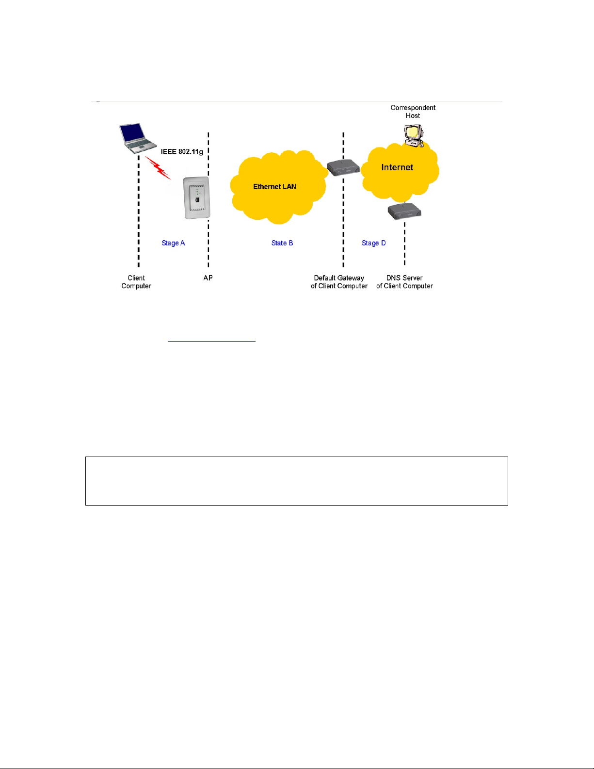
B-2: TCP/IP Settings Problems
Fig. 52. Communication stages for a client to reach its correspondent host
For a wireless client computer to communicate with a correspon dent host on the Internet by the host’s
domain name (e.g. http://www.wi-fi.com
), it first sends a DNS request to a DNS server on the Internet.
The DNS request travels first to the AP, then the HD24613 relays this request to the default gateway
of the client computer. Finally, this request is forwarded by the gateway to the DNS server on the Internet. The DNS reply issued by the DNS server is transmitted back to the client computer following a
reverse path. When the client computer receives the DNS reply, it knows the IP address of the correspondent host and sends further packet s to this IP address.
As illustrated in Fig. 52, the communication path could be broken at some of the stages. The
OS-provided ne twork dia gnostic to ol, ping.exe, can be employed to find out TCP/IP-related communication problems.
NOTE: If two or more NICs are installed and operating on a client compu ter, TCP/IP may not wor k
properly due to incorrect entries in the routing table. Use the OS-provided command-line network
tool, route.exe, to add or delete entries from the routing table. Or, use Windows-provided Device
Manager to disable unnecessary NICs.
Solve the following problems in order:
z The HD24613 does not respond to ping from the client computer.
Are two or more NICs installed on the client computer?
Use the OS-provided comma nd-line network tool, route.exe, to modify the contents
of the routing table.
Use Windows-provided Device Manager to disable unnecessary NICs.
Is the underlying link (Ethernet or IEEE 802.11g) established?
Make sure the Ethernet link is OK.
Make sure the wireless settings of the wireless client computer and of the HD24613
41
Page 47

match.
Are the IP address of the client computer and the IP address of the HD24613 in the same IP
subnet?
Use WinIPCfg.exe or IPConfig.exe to see the current IP address of the client com-
puter. Make sure the IP address of the client computer and the IP address of the
HD24613 are in the same IP subnet.
TIP: If you forget the current IP address of the AP, use Wireless Ro uter/AP Browser
to get the information (see Appendix B-3).
z The default gateway of the client computer does not respond to ping from the
client computer.
Solve the preceding problem first.
Are the IP address of the HD24613 and the IP address of the client computer in the same IP
subnet?
If you cannot find any incorrect settin gs of th e AP, the default gateway may be really down
or there are other communication problems on the network backbone.
z The DNS server(s) of the client computer do not respond to ping from the client
computer.
Solve the preceding problems first.
If you cannot find any incorrect settings of the AP, the default gateway of the HD24613
may be really down or there are other communicatio n problems on the network backbone.
42
 Loading...