


High Country Tek, Inc.
Plug Top Drivers
Electronic Controller Solutions for the
Mobile, Industrial & Marine Fluid Power Industry
High Country Tek, Inc. ( HCT )
Introduces the latest in a range of cost effective
proportional driver products.
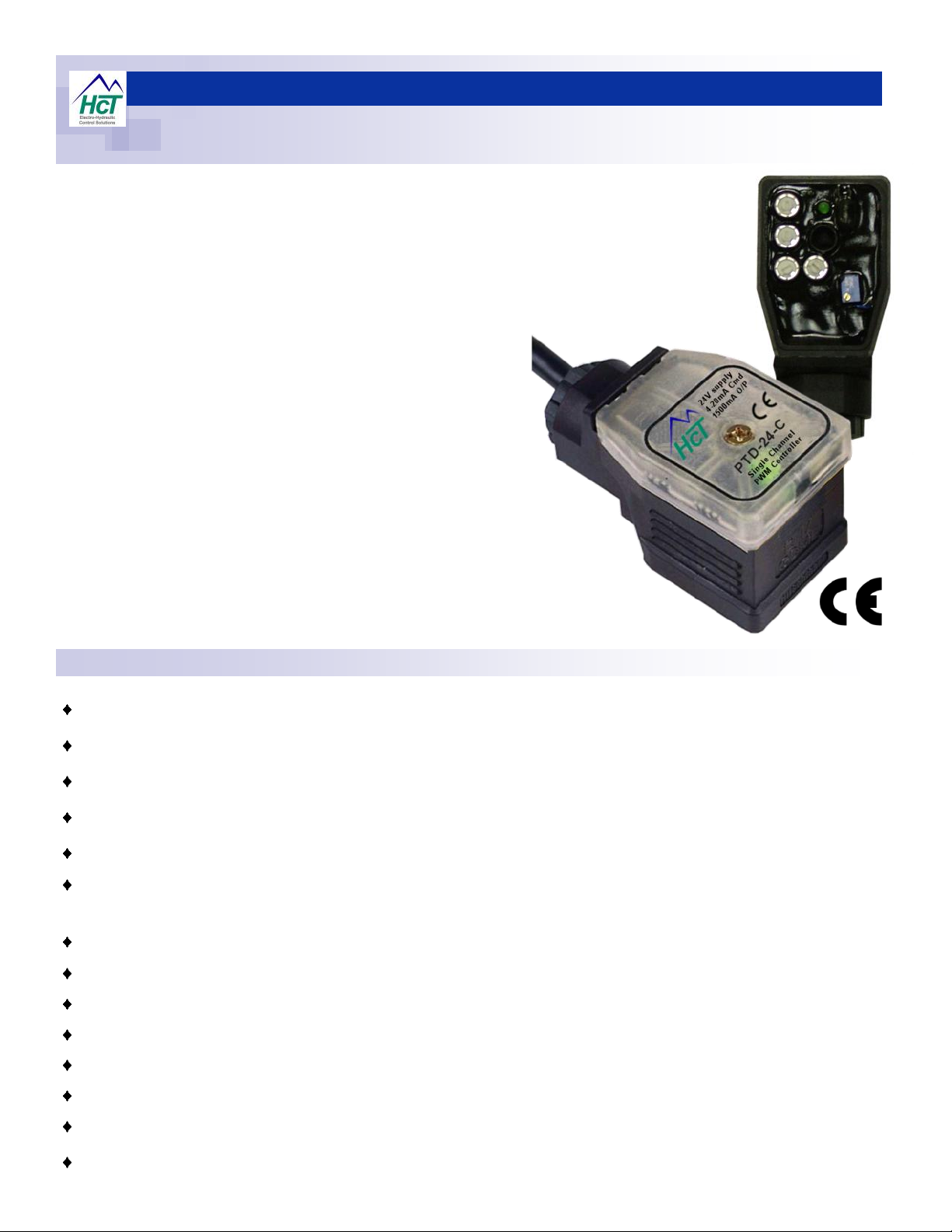
These Plug Top Drivers (PTD) are designed to control
single valve coils, and come in 12 or 24V versions that
can interface with 4-20mA or 0-10V command signals.
Simple analog technology, full CE compliance and HCT’s
signature potting process makes these very physically robust and
ideal for use in valve stack or manifold applications.
Each controller comes pre-wired with 3m/10 feet of 4 core color coded
cable as well as a complete mounting kit allowing secure connection to any
valve with a DIN 43650 interface.
Application Examples:
Single coil proportional pressure , flow or screw-in cartridge control valves.
System load / Unload valves - ‘bumpless’ decompression.
Pump stroker ( single side operation )
Mobile applications where ‘CHASSIS’ or ‘EXTERNALLY’ mounted.
High Vibration and /or ‘G’ force applications.
High Humidity applications and/or marine usage.
Cost conscious applications.
www.highcountrytek.com
Copyright © High Country Tek, Inc. - 2009

Electronic Controller Solutions for the Fluid Power Industry
Application Guidelines:
ALWAYS - Take a few minutes to FULLY read THESE information / data sheets BEFORE starting.
ALWAYS - Keep High Voltage AC cables separate from Low Voltage DC signal and supply cables.
ALWAYS - Make sure the unit supply voltage is the same as the coils on the valve being driven !
ALWAYS - Ensure that you are aware of the available adjustments and consequences on the electronics and hydraulics.
ALWAYS - Make sure you have the correct tools to do the intended job ( i.e. P.C., software ) e.t.c.
ALWAYS – ‘Isolate’ this unit from all other equipment BEFORE any form of welding takes place.
ALWAYS - Check ALL connections to and from this unit to ensure NO short or OPEN circuits.
ALWAYS - Check the units supply voltage is CORRECT, ‘ ELECTRICALLY CLEAN ’ and STABLE.
ALWAYS - Operate the units within specified operating temperature for best & reliable performance.
ALWAYS - Ensure that any unused wires / terminals are terminated safely and not shorted together.
ALWAYS - Isolate the controller if ANY form of battery charging or battery boosting takes place on the vehicle.
ALWAYS - Ensure ALL valve connectors are wired correctly, secure, locked and connected to correct coils.
ALWAYS - Use screened / shielded wires wherever possible to avoid electrical noise that may be present.
ALWAYS - Make sure the cable screen IS connected to GND at one end only - typically the user power supply terminal.
ALWAYS - Use a wire gage that is rated for the voltage and current associated with this units operations
ALWAYS - Observe the set-up procedures in this manual for best operational results.
ALWAYS - Follow and abide by local and country health and safety standards – protect yourself and others !
NEVER - Arc Weld or Charge Batteries with this driver unit connected as damage can occur.
NEVER - Attempt to use this unit if you are unsure of electrical OR hydraulic connections or expected operation.
NEVER - Attempt to use this unit in Areas where other AC or DC coils HAVE NOT been fully suppressed.
NEVER - Use a power supply that is not rated for the correct required O/P current under full load.
NEVER - Allow wires TO or FROM the unit to short circuit ( to each other or chassis/cabinet e.t.c. ).
NEVER - Attempt to use this unit in areas of intense RF without adequate screening measures.
NEVER - Disconnect or connect wires to or from this unit unless it isolated from the power supply.
NEVER - Use this unit in temperatures that exceed those specified as operation may be effected.
NEVER - Start this unit without ensuring ALL work areas are clear of personnel !
The information in this guide is the intellectual property of High Country Tek, Inc. and should be considered at all times
as strictly company confidential.
It shall not be copied or transmitted by any format to any third parties without our knowledge and express written
permission.
HCT reserves the right to improve this product at any time without notice.
Please check our website www.highcountrytek.com for latest versions of this manual.
Electronic Controller Solutions for the Fluid Power Industry
Plug Top Driver Overview:
The High Country Tek, range of PTD’s is available in four (4) versions to suit virtually any
application need.
The Voltage command versions can accept 0-10VDC while the Current Command versions
can use the industry standard 4-20mA.
Choose from one of the part numbers below for the correct unit that matches your
requirement:
Part Number -
PTD-12-V - 12V supply, Voltage command, 3000mA O/P current
PTD-24-V - 24V supply, Voltage Command, 1500mA O/P current
PTD-12-C - 12V supply, Current command, 3000mA O/P current
PTD-24-C - 24V supply, Current Command, 1500mA O/P current
12V and 24V PTD Technical Specifications::
Housing Type:- Plug top style using HCT unique ‘encapsulated’ process.
Input Supply Voltage: 12VDC or 24VDC nominal, both ±20% ( Absolute Maximum )
Input Supply Current: Valve Current Setting + ~200mA Quiescent (Max)
Command Input Type(s): Voltage OR Current depending on model used
Command Input Value(s): 0 to +Vref or external 0 - 10VDC max OR 4-20mA depending on model used.
User reference: +12V supply Vref = +8VDC ( ±5%) @ 5mA max
+24V supply Vref = 15VDC ( ±5%) @ 5mA max
Ramp Times (all models) : 300mS to ~8 Secs ( with I max at 100% ) with separate UP and Down settings
Dither Frequency (all models) : Adjustable, ~100 to ~250Hz ( ± 20%)
Housing Material:- High Impact resistance ABS.
Wire Connections:- 3Meters / 10feet pre-connected 4 core, color coded cable to DEF. standard.
Encapsulation:- Flameproof. Black epoxy resin filled
Mounting:- DIN 43650 connector footprint
Temperature range:- -20 to +70 ºC ( operational )
NEMA/IP Rating: NEMA 6P/67 when assembled and mounted to coil correctly

Electronic Controller Solutions for the Fluid Power Industry
+V Supply
0VDC
10K
Potentiometer
BLUE
GREEN
YELLOW
RED
+VRef
+V Supply
0VDC
+I-I
BLUE
GREEN
YELLOW
RED
External Signal
4-20mA
0VDC
0V
BLUE
GREENYELLOW
RED
+V
External Signal
0 to +10VDC
+VRef. NOT USED
Terminate Safely.
+V Supply
Voltage Command Connection Details:
PTD voltage input (GREEN wire ) is internally pulled to
0V to prevent spurious operation with no command
signal connected.
Ramps DO NOT work if power is dis-connected.
Use internal reference voltage +Vref for local control with
potentiometer or joystick e.t.c.
HCT recommends 10KΩ potentiometers / joysticks.
+Vref is protected and current limited to ~5mA.
12VDC PTD’s have +8VRef output.
24VDC PTD’s have +15VRef output.
Always use screened wires wherever possible.
PTD voltage input (GREEN wire ) is internally pulled to
0V to prevent spurious operation with no command
signal connected.
Ramps DO NOT work if power is dis-connected.
Use 0-10V maximum command signal input.
Ensure external command signal source is connected to
same GND (0V) as the PTD power supply for correct
operation.
Ensure +VRef is terminated safely to avoid shorts.
Always use screened wires wherever possible.
Current Command Connection Details:
PTD current input uses a 250Ω shunt resistor connected
to GND (0V) internally
Yellow wire (-ImA) is internally connected to GND (0v)
supply
4-20mA command is connected between +I and –I
Ramps DO NOT work if power is dis-connected.
Use 4-20mA maximum command signal input.
Always use screened wires wherever possible.
FUSES:
For clarity, no fuses are shown here.
HCT strongly recommends that the user installs a fuse
holder that if fit for purpose in the application and uses a
correctly rated fuse for each plug top driver to ensure
that damage does not occur under short circuit or wiring
circumstances.

Electronic Controller Solutions for the Fluid Power Industry
PWM
F.E.T.
output
stage
I Max ( 20 Turn potentiometer )
‘Di ther’ ( PWM )
frequ ency adjust
I Min adjust
Ramp UP
Ramp
DOWN
+V Supply
GND (0v)
Command
Sig + I/P
Internal
PSU
Current
Feedback
PWM ‘ f ’
generator
Output to
valve coil
interface
Command
Scalin g
Ramp
Generator
+Vref O/P
PWM
F.E.T.
output
stage
I Max ( 20 Turn potentiometer )
‘Di ther’ ( PWM )
frequ ency adjust
I Min adjust
Ramp UP
Ramp
DOWN
+V Supply
GND (0v)
Command
Sig + I/P
Internal
PSU
Current
Feedback
PWM ‘ f ’
generator
Output to
valve coil
interface
Command
Sig - I/P
250Ω
shunt
Ramp
Generator
Ful ly Anti-Clockwise = ~100Hz
Ful ly Clockwise = ~250Hz
Cmd
Clo ckwise adjustment =
Hig her I Min.
‘I Min’
adjustment.
Iout
Clo ckwise adjustment =
Slower ramp UP.
Output Current
Adjustment ‘I Max’
t
Clo ckwise adjustment =
Incr ease Output Current
‘Output ON’ led
Ramp ‘UP’ adjustment.
Ramp ‘DOWN’ adjustment.
t
Clo ckwise adjustment =
Slower ramp DOWN.
Dither Frequency
Adjustment.
Plug Top Driver adjustment Location Guide:
1. Ramp UP - single turn potentiometer
2. Ramp DOWN - Single turn Potentiometer
3. Imin adjust - single turn potentiometer
4. Dither Freq. - single turn potentiometer
5. Imax - 20 turn potentiometer
ALL potentiometers are clockwise to
increase their setting
Voltage Command Block Diagram:
Current Command Block Diagram:
RED - +V Supply Input
BLUE - GND (0V) Supply Input
GREEN - Voltage Command I/P
YELLOW - +Vref output to user
IMPORTANT NOTE:
DO NOT short circuit the +Vref to +Supply
or GND(0V) as damage to the PTD will
occur!
RED - +V Supply Input
BLUE - GND (0V) Supply Input
GREEN - +ImA Current Input
YELLOW - -ImA Current Input
NOTE:
-ImA current input is INTERNALLY
connected to GND (0v) supply input and
is NOT isolated.

Electronic Controller Solutions for the Fluid Power Industry
Adjustment Guide for all PTD series:
• Plug the PTD onto valve coil to be driven - DO NOT use mounting screw at this time.
• Remove securing screw and opaque lid to reveal internal adjustments.
• Ensure command signal ( voltage or current ) is set to zero.
• Ensure that all user made wire connections are correct and secure.
• Turn I Min potentiometer Anti-Clockwise to minimum - Single turn adjustment.
STEP 1
STEP 2
• Turn I Max potentiometer 20 turns Clockwise to maximum.
• Turn Ramp UP & DOWN potentiometers fully Anti-Clockwise to minimum.
• Apply correct supply voltage to the plug top driver.
• Slowly increase command voltage to approx 10% of maximum.
• Use the I Min adjustment to give minimum valve response ( flow or pressure ) required.
• Slowly Increase command signal to maximum setting.
• Adjust I Max until desired valve maximum response ( flow or pressure ) is achieved.
• Change command signal from zero to max and adjust RAMP UP setting to suit application.
• Change command signal from max to zero and adjust RAMP DOWN setting to suit application
• Confirm the ‘Output ON’ LED is changing brightness proportionally with command increase/de-
crease
STEP 3
STEP 4
NOTE:
If the ‘Output ON’ led is switches between OFF or ON bright, this indicates the PTD is not connected to the coil correctly
OR the coil is open circuit - check PTD connections and coil Ohmic integrity.
If the connections and coil are correct, the PTD has suffered internal damage and needs to be replaced.
• Adjust Dither frequency to suit valve product being driven. .
• Fully Anti-clockwise = approx. 100Hz
• Fully Clockwise = Approx.... 250Hz.
• Set command to zero
• Turn OFF supply voltage to PTD
NOTE:
Different valve types (i.e. cartridge or spool) require different dither frequencies to optimize the performance, stability and
repeatability. It is strongly reccomended that the OEM technical information is read to establish the correct frequency and
ensure the best operation is achieved on the application.
• Replace PTD lid ensuring that it ‘clicks’ into place and the inner seal is maintained.
• Replace securing screw and tighten ( do not over tighten or lid damage is seen )
• Unit is now ready for continuous application use
STEP 5

Electronic Controller Solutions for the Fluid Power Industry
Liquid tight cable
outlet
Rubber gasket seal in
lid recess.
Driver plug base
to valve coil
rubber gasket
supplied ( loose )
M3 x 40mm mounting
screw
If required, Apply
‘lithium grease’ under
lid ( fill ) and between
driver plug base,
gasket and valve coil
connector.
Mechanical Data:
NOTE:
Controller interfaces with industry standard
DIN 43650 - 3 pin connector as shown
Housing Type:- Self contained DIN ‘Plug Top’
Housing Material:- High Impact Resistant Molded ABS.
Housing Colour:- Black / dark Grey.
Surface Finish:- Matt.
Housing Thickness:- 2mm ( Mounting Flange and Face ), 1.7mm All Internal Dividers.
Lid material:- High Impact Resistant Molded ABS.
Lid Colour:- Opaque clear.
Lid finish:- Matt.
Unit size:- See above size detail drawings.
Unit Weight:- Approx.... 400 grams ( including Encapsulation material & Cable )
Wire entry:- Pre-wired and sealed via PG11 gland to fixed cable.
Encapsulation:- Flame Resistant, Black , Two Part Epoxy Resin.
Wire length:- Approx...... 3 Meters colour coded cable
Wire specification:- 4 core, 16/02 with PVC outer protection to Def Standard 16-12 Part 5
( Screened ) 2.5 Amps/core @ 70°C Max Operating Temperature.
Severe Environment Application Guide:
Wherever possible, mount valve and PTD
so that debris or liquid will drain away or off
the surface.
Mount PTD so that liquid tight cable exit
gland is facing down or away from the
direction of debris or liquid flow.
Use care when re-assembling unit after
adjustment and ensure that lid gasket is in
place. DO NOT over tighten the central M3
x 40mm mounting screw.
Ensure that flat rubber gasket
( supplied ) is fitted between valve coil
and driver plug.
For ‘high moisture’ applications apply ‘lithium grease’ between valve coil and driver plug base before final assembly and mounting
screw tightening process.
For total immersion applications, follow above step and additionally fill driver plug lid with ‘lithium grease’ after adjustment and
before final assembly to form liquid proof seal around all potentiometers and units plug base / valve coil joint.
Refrain from high pressure washing that enables liquids to get between the PTD and the coil connector.

Electronic Controller Solutions for the Fluid Power Industry
Troubleshooting Guide:
There is Not enough pressure or flow at maximum command input:
1) Increase the ‘I Max’ setting until the required levels are achieved.
There is very little control at the lower end of the command signal:
1) Increase the ‘I Min’ setting until the required levels are achieved.
Cannot achieve full flow or pressure at full command and full ‘I Max’ adjustment:
1) Check supply voltage is at nominal levels and is stable ( not collapsing ) under full load conditions.
2) Ensure that the coil fitted to the valve is correct for the supply voltage( I.e. 12V coil for 12V supply ).
3) Check that the command signal used is achieving expected maximum level at the PTD input wire.
4) If using a potentiometer or joystick, ensure that the value is 10K to avoid loading the PTD +Vref.
NOTE: Remember, if the supply voltage is reduced, the output current to the coil will also be reduced resulting in the valve not
being able to achieve full displacement.
The unit does not respond to an external command voltage:
1) Ensure that the external command source’s GND (0V) is connected to the PTD’s GND (0V) wire.
2) Check continuity of command cables between source and driver unit.
The output from the driver goes between zero and full on only with no proportionality:
1) Ensure that there is a coil connected to the PTD output.
2) Check that the coil is not open circuit.
3) Check the command voltage is proportional.
The unit is completely dead with the led not coming on at all:
1) Check that the supply voltage is present & correct
2) Check the supply input fuse for continuity and correct fitting.
3) Check that there is a command connected and correct to the PTD
4) The unit is damaged and needs to be replaced.
The unit is very slow to respond to command input signals:
1) Re-adjust the PTD’s ‘Ramp Generator’ settings to get required response.
The valve appears to have large hysteresis and does not respond correctly:
1) Adjust the driver units ‘Dither Frequency’ settings to get required response.
For more information on application of these plug top drivers, visit our website or contact our customer ser-
vice department, details on how to reach them are on the back page of this information manual.
www.highcountrytek.com

Command Signal 0 to 100%
Output Current into Inductive Coil Load
Curve applies to:
• PTD-12-C
• PTD-12-V
• PTD-24-C
• PTD-24-V
Product Operation Notes
Current set 600mA
High Country Tek, Inc PTD with Current regulation.
0
0.1
0.2
0.3
0.4
0.5
0.6
0.7
Time in Minutes
Current ( mA )
HCT PTD Current O/P
Voltage Control
Electronic Controller Solutions for the Fluid Power Industry
This diagram clearly
shows the linearity of the
controllers output current
relative to an analog
linear 0-100% command
signal.
The use of internal
current and other
innovative feedback
allows HCT to ensure
that the plug top driver
will not negatively
influence any product that
it is connected to and will
allow the user to faithfully
follow the mechanical/
fluid curves expected.
The diagram below shows how the use of current feedback allows HCT to provide an automatically compensated output
current, irrespective of minor supply voltage fluctuations and coil heating effects. This allows the operator to fully use the
characteristics of the product under control with virtually no reduction in specification.

Notes
Electronic Controller Solutions for the Fluid Power Industry

Notes
Electronic Controller Solutions for the Fluid Power Industry

Electronic Controller Solutions for the Fluid Power Industry
The electronic Plug Top Driver (PTD) unit described here MUST be used and mounted in the manner described in this Information
sheet to fall in line with current regulations on EMC.
By issuing this document, High Country Tek, Inc are showing their commitment and due diligence to the rules concerning EMC from a
global perspective.
A reduced supply voltage will directly effect the valves maximum achievable performance figures regarding flow or pressure.
ALWAYS ensure that the P.T.D. is supplied with the nominal supply voltage as recommended by this literature and the valve coil
manufacturer to get the best results and full control range from the hydraulic product being controlled.
ALWAYS follow connection, application and usage instructions provided with this electronic unit.
ALWAYS ensure that ANY Earth connection is to clean, bare metal and NOT a paint finish.
ALWAYS ensure that NO High Power RF is used near or inside an open enclosure.
ALWAYS mount this unit such that any collected moisture or liquid will be able to escape.
This unit is CE compliant, flame proof but NOT intrinsically safe rated.
Use a Switch Mode Power Supply (SMPS) where possible for the supply voltage on these plug top drivers as they are designed to
work from multiple line voltages/frequencies ( 50 or 60Hz), can supply the high instantaneous current demands created by PWM
control of valve coils and have integrated filters for electrical noise.
Mining & Exploration
Agriculture
Cranes & lifts
Refuse & Re-cycling
Construction
Off-Road vehicles
Forestry, Wood & Pulp
Reclamation & Salvage
Oil Field & Sands
Demolition Equipment
Cooling Solutions
Military Apparatus
Specialty Use
Remote Control
Power Generation
Emission Controls
www.highcountrytek.com
High Country Tek, Inc.
208 Gold Flat Court
Nevada City, CA, 95959
Tel: (1) 530 265 3236
Fax:(1) 530 265 3275
Integrated Drivers
This data sheet may contain mistakes and printing errors. The information in this
publication is regularly checked and corrections made in the next issue. Please
Valve & Pump Controls
PTD-XX-X-C.pub/GG/09 Copyright © High Country Tek, Inc. - 2009
check our website for latest version. HCT accepts NO liability for technical
mistakes or printing errors, or their consequences.
 Loading...