

HCT HGC-2 User Manual
Beware of HIGH VOLTAGE when operating any
generator system – high voltage can be LETHAL –
observe ALL laws, by-laws and health & Safety
recommendations for your immediate location,
state and/or country.
High Country Tek, Inc.
HGC-2 Initial Installation Guide
Electronic Control Solutions for the Global Fluid Power Industry
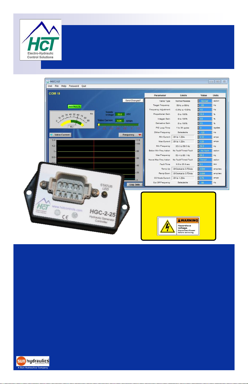
HGC-2 Product Features:
Full PID closed loop speed controller for use with AC generator systems
Customer selectable voltages and frequencies for global applications
Operates with all major OEM electro-hydraulic valve and pump equipment
Industry standard Deutsch 12 way connector protected to >IP69K ( NEMA 6P )
Environmentally hardened by ’Solid’ potting with flame retardant materials
Full CE compliance for confident global application on all mobile equipment
Comprehensive on-line literature, manuals, user guides and application information
Fully configurable by PC based user interface for set-up and diagnostics
Fast, easy and reliable development-to-production timeline across multiple platforms
U.S.A. designed, built and supplied
www.hctcontrols.com

Hydraulic generators can produce LETHAL voltages
when operating.
Remember to abide by all health and Safety rules and
keep yourself and work colleagues safe !
Electronic Controller Solutions for the Global Fluid Power Industry
Application Hints & Tips:
ALWAYS do the following:
Take a few minutes to FULLY read THESE information / data sheets BEFORE starting.
Isolate this unit from all other equipment BEFORE any form of welding takes place.
Isolate this unit if ANY form of battery charging or boosting takes place on the vehicle.
Isolate this unit if ANY form of alternator ‘load dump’ testing takes place.
Keep ALL High Voltage AC cables separate from Low Voltage DC cables.
Make sure the module supply voltage is correct and connected.
Ensure correct fuses are used and replaced with correct value to avoid system damage.
Ensure that you are aware of the adjustments and consequences on the electronics
Make sure you have the correct tools to do the intended job ( i.e. P.C., software ) etc.
Check ALL connections to and from this unit to ensure NO short or OPEN circuits.
Check the units supply voltage is CORRECT, ‘ ELECTRICALLY CLEAN ’ and STABLE.
Operate the units within specified operating temperature for best & reliable performance.
Ensure that any unused wires / terminals are terminated safely and not shorted together.
Ensure ALL connectors are wired correctly, secure and locked in place.
Observe the set-up procedures in this manual for best operational results.
ALWAYS follow and abide by local and country health & safety standards.
ALWAYS protect yourself and consider others !
NEVER do the following:
Arc Weld or Charge Batteries with this driver unit connected as damage can occur.
Use this unit if you are unsure of electrical OR hydraulic connections or expected operation
Use this unit in Areas where other AC or DC coils HAVE NOT been fully suppressed.
Use a power supply that is not rated for the correct required O/P current under full load.
Allow wires TO or FROM the unit to short circuit ( to each other or chassis/cabinet e.t.c. ).
Attempt to use this unit in areas of intense RF without adequate screening measures.
Disconnect or connect wires to or from this unit unless it isolated from the power supply.
Use this unit in temperatures that exceed those specified as operation may be effected.
Start this unit without ensuring ALL work areas are clear of personnel !
2
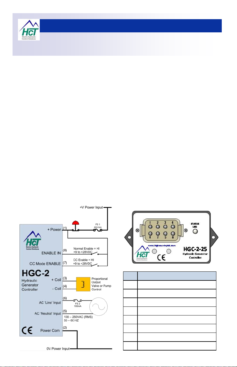
Pin Function
1 +VDC Input Supply
2 0VDC Input Supply
3 +Solenoid Connection O/P
4 -Solenoid Connection O/P
5 AC feedback Neutral I/P
6 AC feedback Line I/P
7 Constant Current Mode enable I/P
8 Controller ENABLE I/P
Electronic Controller Solutions for the Global Fluid Power Industry
HGC-2 Connection Information:
Housing Type:- HCT unique ‘encapsulated’ block.
Input Supply Voltage: 9 – 28VDC ( Absolute Maximum )
Input Supply Current: Valve Current Setting + 50mA Quiescent (Max)
Feedback Voltage:- 100 to 250VRMS
Feedback Frequency:- 50 or 60Hz with +/-3Hz adjustment
O/P Current Ranges:- 600mA, 1.2A or 2.5A
Dither Frequency : Software adjustable, ~50Hz to ~1KHz
Housing Material:- ABS, black
Wire Connections:- 8 pin Deutsch - DTS06 - Male
Encapsulation:- Flameproof epoxy resin
Mounting:- 2 x No. 6 ( 4mm ) screws .
Temperature range:- -20 to +80 ºC ( operational )
NEMA/IP Rating: NEMA 6 / 67 ( module only )
Operating System: Windows® XP Professional / Vista
Business and Ultimate Compatible
Unit Settings: All by PC user interface
3
 Loading...