

HCT HFS-3 User Manual
High Country Tek, Inc.
Hydraulic Fan System Controller - HFS-3-12v
Electro-Hydraulic Solutions for Mobile, Industrial & Marine Applications.
Hydraulic Fan System
Controller – 12V – 1200mA
Application, Set-up
&
Information Manual.
Part No. HFS-3-12v RevC November 2009

Hydraulic Fan System Controller – HFS-3-12v
Important Notes:
This product has been designed by High Country Tek, Inc ( HCT ) to interface directly with any manufacturers
range of proportional pressure and/or flow control valves, variable pumps, motors and manifold blocks currently
available for this type of system.
Please contact the factory by the e-mail address given below or nearest High Country Tek, Inc. distributor for
further technical information and availability.
Application Areas:
• ON and OFF road application suitability
• OEM, re-power and retro-fit markets
• Mining equipment – above and below ground
• Drill, exploration and blast hole rigs
• Chassis, bus and RV builders
• Static applications – standby generators
• Industrial cooling operations
• Liquid nitrogen/oxygen temperature conditioning
• Hydraulic system oil
• Automatic Transmission fluid
• Engine sump oil
• Air conditioner refrigerant
• Engine water jacket
• Engine charge air
• ‘External Attachment’ system fluids
• Diesel fuel conditioning
System Part Numbers:
• Controller Module with DIN 43650 connector :-………………………………………….….P/No: HFS-3-12v
• Controller info manual:-……………………………………………………..……….……..…………P/No: HFS-3-12v RevC
IMPORTANT NOTE:-
High Country Tek, Inc. reserves the right to upgrade, revise or better any controller as technology improves without
notice being given.
Wherever possible, full downwards compatibility for both hardware and software on replaced controllers will be
maintained but it is the users responsibility to ensure that the latest technical details or literature is being used for
application reference.
If you are unsure of the literature, hardware or software revisions you have, or suspect that it is an older revision,
please send an e-mail request for the latest releases to info@highcountrytek.com
ALL information contained herein is copyrighted to High Country Tek, Inc - © 2009.
2

Hydraulic Fan System Controller – HFS-3-12v
Product Overview:
This driver unit has been designed to interface and operate with:-
• Wide supply range 10VDC to 14VDC ( 12V nominal )
• Engine Control Unit ( ECU ) 5% to 95% PWM output with 0.5 to 4.5V ( based on 5V maximum ) and
• PWM frequency input from 20 – 125Hz.
• Fan system control manifold blocks.
• Vane and Gear motorswith internal or external pressure control valves.
• Piston pump with remotecompensatorusing proportional pilot pressurevalves.
• Systems with 12VDC cartridge valves as fluid controlling elementsPositive or Negative logic.
Product Features:
Self contained controller plug for Mobile, Industrial or Marine Hydraulic fan cooling systems.
Interfaces directly with engine PWM fan speed signal.
Space saving - ‘ON-Valve’ mounting using standard DIN 43650 connector.
EMC compliant product to EN50081-1 and EN50082-2 ( heavy industrial )
1 x proportional MosFet driver output ( PWM ) at upto 1200mA ( @12VDC ).
Sealed and environmentally protected to IP68 or NEMA 6P
Flame proof resin ‘Encapsulated’ version to suit application environment.
No extra DIN housing or ‘Card Holder’ to buy.
Pre-wired with 3 meters ( ≈10 ft ) of colour coded cable for fast reliable connection.
Fully ‘isolated’ design for improved safety and ease of application difficult areas.
Unit status ‘Diagnostic’ LED visible through opaque plug cover.
Low cost compared to other available modules with comparative functions.
Easy to use ‘top entry’ adjustments for all major parameters..
Single turn potentiometer ( 1 turns ) ‘I Min’ adjustment for driven solenoid
Multiturn potentiometer ( 20 turns ) ‘I Max’ adjustment for driven solenoid.
‘Dither’ frequency Variable ( single turn ) from 100Hz to 250Hz ( +/-20%).
Heavy duty approved cable for all application environments.
Protected inputs and user outputs for maximum reliability and product life.
ALL information contained herein is copyrighted to High Country Tek, Inc - © 2009.
3

Important Notes:
ALWAYS - Take a few minutes to FULLY read THESE information / data sheets BEFORE starting.
ALWAYS - Keep High Voltage AC cables separate from Low Voltage DC signal and supply cables.
ALWAYS - Make sure the unit supply voltage is the same as the coils on the valve being driven !
ALWAYS - Ensure that you are aware of the available adjustments and consequences on the electronics and hydraulics.
ALWAYS - Make sure you have the correct tools to do the intended job ( i.e. P.C., software ) e.t.c.
ALWAYS – ‘Isolate’ this unit from all other equipment BEFORE any form of welding takes place.
ALWAYS - Check ALL connections to and from this unit to ensure NO short or OPEN circuits.
ALWAYS - Check the units supply voltage is CORRECT, ‘ ELECTRICALLY CLEAN ’ and STABLE.
ALWAYS - Operate the units within specified operating temperature for best & reliable performance.
ALWAYS - Ensure that any unused wires / terminals are terminated safely and not shorted together.
ALWAYS - Isolate the controller if ANY form of battery charging or battery boosting takes place on the vehicle.
Hydraulic Fan System Controller – HFS-3-12v
ALWAYS - Ensure ALL valve connectors are wired correctly, secure, locked and connected to correct coils.
ALWAYS - Observe the set-up procedures in this manual for best operational results.
ALWAYS - Follow and abide by local and country health and safety standards – protect yourself and others !
NEVER - Arc Weld or Charge Batteries with this driver unit connected as damage can occur.
NEVER - Attempt to use this unit if you are unsure of electrical OR hydraulic connections or expected operation.
NEVER - Attempt to use this unit in Areas where other AC or DC coils HAVE NOT been fully suppressed.
NEVER - Use a power supply that is not rated for the correct required O/P current under full load.
NEVER - Allow wires TO or FROM the unit to short circuit ( to each other or chassis/cabinet e.t.c. ).
NEVER - Attempt to use this unit in areas of intense RF without adequate screening measures.
NEVER - Disconnect or connect wires to or from this unit unless it isolated from the power supply.
NEVER - Use this unit in temperatures that exceed those specified as operation may be effected.
NEVER - Start this unit without ensuring ALL work areas are clear of personnel !
The information in this guide is the intellectual property of High Country Tek, Inc. and should be considered at
all times as strictly company confidential.
It shall not be copied or transmitted by any format to any third parties without our knowledge and express
written permission.
4

Hydraulic Fan System Controller – HFS-3-12v
Important Notes:
High Country Tek, Inc ( HCT ) recognizes that fan drive systems are an important part of the protection
needed for the engine and associated peripheral components to ensure maximum reliability, productivity
and long term operation. The fan drive system controller, HFS-3-12v offered by HCT will save fuel, reduce
emissions ( particle and noise ) and increase application productivity by only operating the fan when
required and matching the fan speed to the heat load that requires dissipation.
For fail-safe operation, HCT strongly recommends that the hydraulic valves used are of the ‘Negative logic’
variety. This means that the valve gives less pressure for an increasing drive current. This choice results in
full pressure and therefore defaults to full fan speed in the event of the electronic controller or the fan
speed requirement signal being dis-connected or disabled.
There are situations where full fan speed with no drive current may not be optimal so the controller in this
manual allows the user the choice of either ‘negative logic’ or positive logic ( Increasing pressure with
increasing current ) valves by a simple link setting, found under the units lid.
Because the controller is designed to connect directly to the engine ECU, all the decisions on ramp rates,
proportionality, slope angle e.t.c. are already calculated to suit the application. This means that adjustment
of the controller is simple with only five potentiometers –
Dither frequency ( which is needed to ensure correct, repeatable and smooth valve operation ).
I Min ( which sets the Max fan speed on Negative logic valves or Min fan speed in positive logic circuits ).
I Max (which sets the Min fan speed on Negative logic valves or Max fan speed in positive logic circuits).
To maintain operational integrity and prevent unauthorized adjustments once set, the assembly of the
driver is such that the enclosure containing the electronics ( electronic printed circuit board and
components are fully isolated from the casing ) must be assembled as described in this manual and
mounted to the valve coil with the correct length screw.
The controller electronics are fully encapsulated in black flame proof resin to allow continuous operation in
adverse conditions while protecting them from vibration and external environmental influences.
This unit has been designed to meet all the current EMC requirements and is a well proven control circuit
with many years of field and time proven operation.
Important Note:-
Please be aware that fan blades can start rotating without warning and may cause
personal injury if precautions are not taken and safe working practices observed.
ALL information contained herein is copyrighted to High Country Tek, Inc - © 2009.
5
Hydraulic Fan System Controller – HFS-3-12v
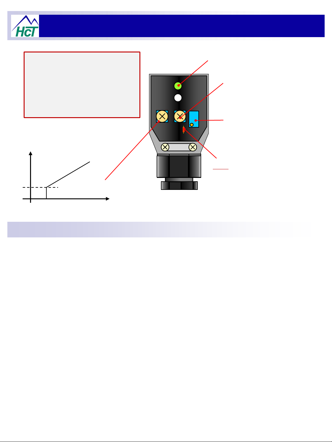
Note:
The output ramp UP and DOWN rate is
decided by the engine ECU rate of change
to the PWM signal.
The HFS3 controller is designed to track
and follow this command as closely as
possible to give optimized fan speed
operation.
TOP VIEW OF PLUG
DRIVER WITH LID
REMOVED.
‘Output ON’ led
Dither Frequency
Adjustment.
Fully Anti-Clockwise = ~100Hz
Fully Clockwise = ~250Hz
Output Current
Adjustment ‘I Max’
Clockwise adjustment =
Increase Output Current
‘I Min’ adjustment.
Iout
Clockwise adjustment
= Higher I Min.
Cmd
Output invert Select link
Default
Inverted valve drive O/P drive = link intact
Non-inverted valve O/P drive = link cut
Product Specifications:
1) Board Style: HCT Unique Size and Mounting.
2) Connector Type: DIN 43650
3) Cable Type: Pre-connected 3M (~10ft) colour coded cable fitted.
4) Input Supply Voltage(s): 12V D.C. ( +10 - +14VDC absolute maximum )
5) Input Supply Current ( Max ): Maximum Valve Current Setting + 50mA Quiescent (Max)
6) Command Input Type: PWM ( From ECU ).
7) Command Input Value: 5V ( 10% to 90% PWM typical range ).
8) Command Input Frequency: 20 to 125Hz
9) Available adjustments: I Max, I Min,
Dither Frequency adjust.
11) Dither Frequency : Variable from 100Hz to 250Hz ( +/- 20% )
12) Environmental: Totally ‘ENCAPSULATED’ Printed Circuit Board.
13) IP Rating: IP68 ( Min ) ( When assembled correctly )
14) NEMA Rating: NEMA 6P
15) Humidity: 95% Non Condensing.
16) Storage temp.: 120 Deg C ( Max )
17) Working temp.: -20 Deg C ( max ) to +70 Deg C ( Max ) Inc Ambient.
6
 Loading...