

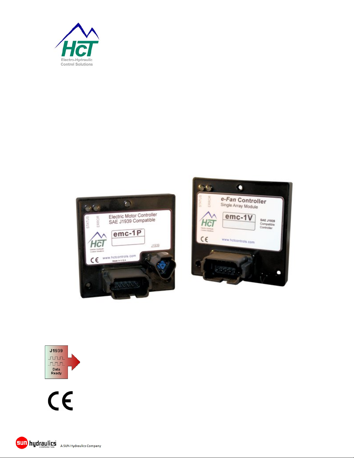
e-Fan Cooling System Controllers
with J1939 Interface
emc-1P & emc-1V
e-Fan Drive - System Controller
User Guide
High Country Tek, Inc. reserves the right to improve this product at any time and without
notice. This manual may contain mistakes and printing errors. The information in this
publication is regularly checked and corrections made in the next issue. Please check
our website or contact our customer support for latest version. HCT accepts NO liability
for technical mistakes or printing errors or their consequences.
Part No:- 021-00351 Rev 1.0 emc-1P & emc-1V e-Fan System Controller User Guide Page 1

e-Fan Cooling System Controllers
with J1939 Interface
High Country Tek, Inc. (HCT) is North America’s foremost independent designer and
producer of modular, ruggedized digital and analog electronic controller products for the fluid power
industry.
From our factory in California, we build, test and produce ‘specialty’ controllers that provide solutions
for specific everyday functions as well as our ‘DVC family’ of fully adaptable user programmable units
that can be integrated together to enable large area networked system solutions.
The modules are typically used in mobile, industrial and marine applications, but are also applied
successfully in several other growing global market segments.
Because High Country Tek has an industry unique non-repairable product protection system, with
every module encapsulated in solid flame resistant material for maximum durability, electrical integrity
and complete environmental security, we have to deliberately select the highest quality components
from our suppliers at all times, ensuring our 100% operating shipped product.
HCT is also a market leader in many application arenas, including hydraulic generator, e-Fan and
hydraulic fan system controls where significant fuel, emission and operational savings can be realized
by using one of the aforementioned specialty units to optimize the applications operation.
HCT’s market neutrality and flexible product configuration approach offers dependable integration
with virtually any hydraulic OEM products for easy, simple and accurate control of valves, pumps,
sub-systems or systems.
Our best-in-class customer service and product reliability is well known and trusted throughout the
fluid power network and we look forward to working with you in the future.
www.Hctcontrols.com
The information in this publication is intended as a guide only, and High Country Tek, Inc. (HCT) takes
NO responsibility for usage and implementation in any user entered values into the provided GUI
structure.
HCT strongly suggests that the user attends one of the product training courses to ensure correct and full
understanding of this information and to learn further optimized methods of control techniques.
Please contact HCT customer service to book one of the scheduled training dates or to di scuss arranging
a course specific to your company needs.
Thank you for using High Country Tek Inc. Products.
Part No:- 021-00351 Rev 1.0 emc-1P & emc-1V e-Fan System Controller User Guide Page 2

e-Fan Cooling System Controllers
with J1939 Interface
TableofContents
Welcome ....................................................................................................................... 4
Introduction .................................................................................................................. 4
Cautions ....................................................................................................................... 4
Warranty Information .................................................................................................. 4
Controller Updates: ..................................................................................................... 4
’emc-1P & emc-1V’ e-Fan System Controller ............................................................ 5
Product Overview ........................................................................................................ 6
Product Application Guidelines ................................................................................. 7
Software Safety ............................................................................................................ 7
emc-1P & emc-1v Electrical Specification Overview ................................................ 8
emc-1P Module Familiarity ......................................................................................... 9
emc-1P Connection Information ............................................................................... 10
emc-1V Module Familiarity ....................................................................................... 11
emc-1V Connection Information ............................................................................... 12
Error LED Code Descriptions for emc-1P & emc-1V .............................................. 13
Module Connection Descriptions ............................................................................. 14
Serial Communications ............................................................................................. 16
Loading the emc-1P or emc-1V GUI onto Host PC ................................................. 17
System Requirements ............................................................................................... 17
Controller adjustments and Monitor ........................................................................ 18
GUI Menu Options ................................................................................................................... 18
Password Protection ................................................................................................................ 19
Help ......................................................................................................................................... 20
GUI software – Main screen (Dashboard) ............................................................................... 21
Data Logging ........................................................................................................................... 22
General Settings ...................................................................................................................... 23
Unit Settings ............................................................................................................................ 23
Output Settings ........................................................................................................................ 24
Auto Reverse Settings ............................................................................................................. 24
Input Settings ........................................................................................................................... 25
Error Information Log ............................................................................................................... 27
Factory Information .................................................................................................................. 28
Temperature Sensor Information ............................................................................. 29
Main I/O connector & Accessories ........................................................................... 29
On Site Testing .......................................................................................................... 30
emc-1P & emc-1V Dimensional Information ............................................................ 32
RS232 Communication Cable ................................................................................... 33
Part No:- 021-00351 Rev 1.0 emc-1P & emc-1V e-Fan System Controller User Guide Page 3

e-Fan Cooling System Controllers
with J1939 Interface
Welcome
Welcome to the High Country Tek Inc. (HCT) e-Fan cooling systems controller user guide, and thank you
for selecting this HCT controller to use in your application
The following information is designed to allow you to connect, set-up and optimize the emc-1P and emc1V modules.
If you have used HCT products before, you will recognize some of the instructions and settings. For those
of you that are new to HCT, please read the directions with care and be sure that if you have any
questions regarding this industry unique controller, then please contact us using one of the numbers
given on the back page of this manual.
We value our customers, their experience and abilities and ask that if you would like to see any additions,
subtractions or find any errors in this publication, that you contact HCT’s customer service so that we can
correct the information and make sure that our programming community is using the latest information.
If you require urgent support, more information or would like specific programming areas clarified, you can
contact us on the customer support number at 1 530 265 3236 or E-mail us through our website at
www.hctcontrols.com
, giving details of your issue and how we can contact you.
Introduction
This manual is designed to provide information needed for the installation and use of the emc-1P & emc1V e-Fan Cooling System Controllers. Its intended user is qualified trained service personnel that
understand the hazards involved in an electromechanical environment. It is recommended that this
manual be read in its entirety before installation is begun with particular attention paid to caution and
safety information.
Cautions
Changing setup values and limits under computer control while the machine is operating may cause
sudden machine movement, which may lead to possible injury or death. It is strongly recommended that
any moving parts are disabled prior to any alignment procedure whenever possible. In any case, caution
should be exercised during any procedure and work should be completed only by qualified trained
personnel.
Warranty Information
High Country Tek Guarantees this product to be free of defects in materials and workmanship for a period
of one year extending from the date the unit was shipped from the factory. Within this time frame, High
Country Tek will provide evaluation of warranted items free of charge. Warranty repair or replacement will
be at the factory’s discretion. If necessary, contact the factory for return authorization by phone (530)
265-3236, Fax (530) 265-3275, E-Mail info@hctcontrols.com
High Country Tek, Service Dept., 208 Gold Flat Court, Nevada City, CA 95959. To help us serve you
better, please have the units full Model / Part Number and Serial Number available when contacting the
factory for any reason. Do not return products to the factory without prior authorization and a RMA
number attached.
or by writing our service department at,
Controller Updates:
HCT continuously improve the controllers and make additional information and/or features available.
Please check on-line at www.hctcontrols.com
controller information.
for the latest products, updated software and
Part No:- 021-00351 Rev 1.0 emc-1P & emc-1V e-Fan System Controller User Guide Page 4

e-Fan Cooling System Controllers
with J1939 Interface
’emc-1P & emc-1V’ e-Fan System Controller
The emc-1P and emc-1V are the latest additions to the High Country Tek (HCT) family of e-Fan control
modules. These highly cost effective controllers have all the features and input output functionality that
will support a wide range and configuration of e-Fan system applications. As with all of the HCT modules,
the controller is packaged in a small rugged enclosure and encapsulated in flame resistant resin to
withstand extreme conditions in the harsh mobile operating environment.
The modules are ideally suited for today’s OEM, distributor or system builder, with both mechanical and
electrical robustness paramount in the design priority, Windows™ compatible easy to use set-up software
and full CE compliance means this one product can be used across multiple platforms, markets and
applications. This unit’s cost effectiveness will become quickly apparent through the reduction in
inventory costs and stocking needs as well as in the engineering time taken usually associated with the
design to delivery cycle.
Programming of the controller parameters and all diagnostics is done through the RS232 connector
pendant. This is a separate connector from the main or SAE J1939 connector ( as fitted on the emc-1P )
so that optimization or operational observation can be carried out without disturbing the cooling system
operation. When programming, changes or observation of the module function is required, connection
can be made through a standard computer serial connection, either directly via a 9 way ‘D’ type connector
or through an HCT approved USB to serial converter. In all cases, the HCT programming interface cable
(Part No: 999 – 10075, RS232 programming cable) is required for communication from the controller to a
Windows™ based PC.
The controller is designed to make the fan system set-up easy to configure and control. The hardware
contains the framework software where the parameters can be changed depending on the user’s needs
via the PC graphical user interface (GUI).
The GUI has been organized into various user screens that are logical and simple to understand.
Terminology has been used that is commonplace through the mechanical, hydraulic, mobile and electric
fan drive industry to allow easy configuration, set-up and running and is intended to cater for a wide range
of users with varying levels of computer familiarity.
This controller is ideally suited to equipment upgrades as well as installation by OEM’s at machine build
time and offers all the necessary features required by today’s modern engines that use the J1939
communications standard.
The controller will take information directly from the J1939 bus for the common temperatures broadcast
such as Engine Coolant, Charge air and Transmission Oil Temperature making system integration very
quick and easy. Engine RPM is also monitored by the module giving the user an option to control the
engine load during the engine start cycle. (minimum RPM setting) Additional external inputs ( 1x emc-1P
& 2x emc-1V ) from Thermistors may be used to monitor non SAE J1939 temperatures and effect the fan
operation.
The emc-1P & emc-1V products are backed by High Country Tek’s industry leading product reliability,
easy to use software design and market leading customer service and technical support as well as ontime delivery while the well designed and intuitive graphical user Interface (GUI), allows you to program
multiple configurable modes of operation available within the one module.
Part No:- 021-00351 Rev 1.0 emc-1P & emc-1V e-Fan System Controller User Guide Page 5

e-Fan Cooling System Controllers
with J1939 Interface
Product Overview
NO software experience needed to apply this controller successfully.
Pre-written ‘e-Fan Drive’ software for easy, fast system configuration, development and production.
Intuitive Graphical User Interface (GUI) runs on any PC with Windows® XP or newer software (.net
compatible).
9 – 32VDC operation with full reverse polarity and SAE J1455 protection.
CE approved to latest international test standards.
J1939 CAN Bus communications for engine and temperature zone data Inputs
**J1939 temperature data hard coded for:
SPN 109, Engine Coolant Temperature; PGN 65262,
SPN 177, Transmission Oil Temperature; PGN 65272
SPN 105, Engine Intake Manifold 1 Temperature; PGN 65270
Extended -40ºC (-40ºF) to +85ºC (+185ºF) controller operational temperature range.
All inputs and outputs are protected from shorting to ground or the power supply.
Diagnostic LEDs display I/O status and module operation at a glance.
‘Blinking’ error codes for fast on-site ‘health check’.
System wiring and coil fault detection alarms.
Configurable Alarm output for integration into host system.
IP68 (NEMA 6P) rating on module for harsh environment reliability.
Deutsch IP69K connectors for reliable and easy system wiring.
Separate RS232 communications connector for programming, monitoring and diagnostics.
Rugged encapsulated product withstands harsh environments found in mobile applications.
Non Volatile Memory maintains ALL settings without power
Completely user configurable and settings are password protected.
**J1939 PGN Address Note**
If the standard SAE J1939 PGN address for Temperatures or RPM is NOT compatible for a
particular application, HCT can change the PGN numbers as needed and re-issue personalized
program code to you. Please use the contact numbers on the back page of this manual to discuss
this with our customer support personnel.
Part No:- 021-00351 Rev 1.0 emc-1P & emc-1V e-Fan System Controller User Guide Page 6

e-Fan Cooling System Controllers
with J1939 Interface
Product Application Guidelines
ALWAYS do the following
Take a few minutes to FULLY read this manual and accompanying data sheets BEFORE starting.
Keep High Voltage AC cables separate from Low Voltage DC signal and supply cables.
Make sure the unit output voltage is compatible with the equipment being driven!
Ensure that you are aware of the adjustments and consequences for the external equipment.
Make sure you have the correct tools to do the intended job (i.e. P.C., software) etc.
‘Isolate’ this unit from all other equipment BEFORE any form of welding takes place.
Check ALL wire connections to ensure there are no unintended SHORT or OPEN circuits.
Check that the units supply voltage is CORRECT, ‘ELECTRICALLY CLEAN’ and STABLE.
Operate the units within specified operating temperature for the best and most reliable performance.
Ensure that any unused wires / terminals are terminated safely and not shorted together.
Isolate the controller if ANY form of battery charging or battery boosting takes place on the vehicle.
Ensure ALL connectors are wired correctly, secure, locked and connected.
Observe all the set-up procedures in this manual for best operational results.
Follow and abide by local and country health & safety standards – protect yourself and others!
NEVER do the following
Arc Weld or Charge Batteries with this driver unit connected as damage can occur.
Attempt to use this unit if you are unsure of electrical OR mechanical connections or expected operation.
Use a power supply that is not rated for the correct required O/P current under full load.
Allow wires TO or FROM the unit to short circuit (to each other or chassis/cabinet etc).
Attempt to use this unit in areas of intense RF fields without adequate screening measures.
Disconnect or connect wires to or from this unit unless it isolated from the power supply.
Use this unit in temperatures that exceed those specified as operation may be effected.
Start this unit without ensuring ALL work areas are clear of personnel!
Software Safety
The software has been carefully written to give the user the maximum system configuration
flexibility while being transparent in operation and easy to use, even for novice system builders and
operators.
To ensure safety when using the software and to prevent accidental connection to another module
that is not an emc-1P or emc-1V, rules have been written into the software to ensure correct
operation at all times. After program entries, cycle power, to ensure changes are accepted by
the unit.
When the PC running the GUI is first connected to a powered controller, and before any data
exchange can be allowed, a ‘Handshake’ takes place that confirms the internal software (BIOS) is
compatible with the GUI software and only then allows the PC and the module to communicate and
share data.
If at any point during the process above an error or miss-match is detected, or loss of
communication, the GUI software will indicate “OFF LINE” and NOT allow communications until the
problem is corrected.
Part No:- 021-00351 Rev 1.0 emc-1P & emc-1V e-Fan System Controller User Guide Page 7

e-Fan Cooling System Controllers
with J1939 Interface
emc-1P & emc-1v Electrical Specification Overview
Board Style ...................................................... High Country Tek unique size and mounting
Connector Type (Main) ................................... 12 way male Deutsch IP69K rated
Connector SAE J1939 ..................................... 3 way male Deutsch IP69K rated
Communication I/O connector RS232 ............ 4 way Packard MALE (Tower) connector on 6 inch Cable
Communication Type ...................................... Serial data at 57.6K Baud through PC USB/Serial port
Input Supply Voltage ....................................... 9 – 32VDC (absolute maximums)
Input supply current ......................................... ~200mA quiescent + valve currents
Input supply protection SAE J 1455 & User supplied inline
fuse (AGC5 or compatible)
Command Input type Main .............................. SAE J1939 digital date OR
Command type additional - emc-1P ................ 1 x external discrete Thermistor
Command type additional - emc-1V ................ 2 x external discrete Thermistor
Thermistor types ............................................. 2 wire Resistance variety only (see page 29)
Proportional Output Type / Range
emc-1P .................................................... PWM / 33Hz to 500Hz, 0% – 100% Duty Cycle, 0 – 3000mA
emc-1V .................................................... Voltage, 0 – 5 VDC / 0 – 50mA ( short circuit protected )
Alarm Output Type / Range ............................ Discreet Active Low or High / 0 – 3000mA
Alarm Output Protection .................................. Short protection to power and ground
‘Reverse’ input signal range ............................ +5VDC to +V module supply momentary = ON
‘Reverse’ input signal impedance ................... 20K Ohm to ground
‘Fire Event’ input signal range ......................... +5V to +V module supply Fans turn OFF
(0V normal Fan operation)
‘Fire Event’ input signal impedance ................ 100K Ohm
‘Ignition’ input signal range .............................. +5VDC to +V module supply = ON
‘Ignition’ input signal impedance ..................... 20K Ohm to ground
Digital Input De-Bounce (Hold Time) .............. 150mS (triggered on rising edge)
Reverse Indicator output Type / Range .......... Discreet Active High / 0 – 3000mA
Reverse Output Protection .............................. Short protection to power and ground
Industry Compliant .......................................... CE certification to latest standards
SAE J1455 Load Dump
Environmental ................................................. Totally encapsulated unit for mechanical protection
IP rating ........................................................... IP 69K
NEMA rating .................................................... 6P
Humidity .......................................................... 95 – 100% Non-condensing
Storage Temp range ....................................... -60 to + 90°C
Operating temp range ..................................... -40 to + 85°C
Note:
ALL controller and system response adjustments are made through graphical user interface software.
See‘emc-1P & emc-1V Software’ section in this manual for full details.
Part No:- 021-00351 Rev 1.0 emc-1P & emc-1V e-Fan System Controller User Guide Page 8
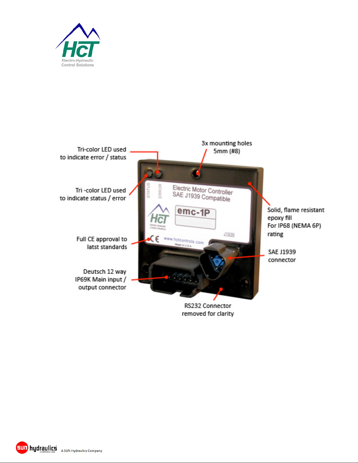
emc-1P Module Familiarity
e-Fan Cooling System Controllers
with J1939 Interface
Part No:- 021-00351 Rev 1.0 emc-1P & emc-1V e-Fan System Controller User Guide Page 9
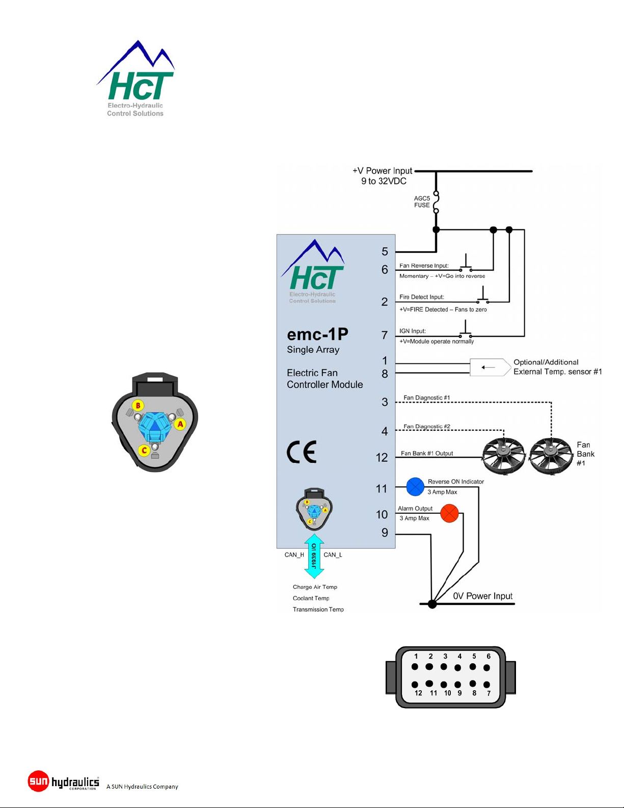
emc-1P Connection Information
NOTE:ControllerMUSThavein‐linefuse
fittedby
userinthe+VPowerInputforsystem
protection.
SAE J1939 Connections
Pin A CAN_Hi (SAE J1939)
Pin B CAN_Low (SAE J1939)
Pin C No connection
Pin 1 ................. Sensor #1 +signal input
Pin 2 ................. Fire detect input
Pin 3 ................. Fan #1 Diagnostic input
Pin 4 ................. Fan #2 Diagnostic input
Pin 5 ................. +Volts 9-32VDC input
Pin 6 ................. Reverse fan input (momentary)
Pin 7 ................. Ignition ON input
Pin 8 ................. Sensor #1 common
Pin 9 ................. Power supply return (GND)
Pin 10 ............... Alarm output (3A max sourcing)
Pin 11 ............... Reverse output (3A max sourcing)
Pin 12 ............... 0-100% PWM e-fan output
e-Fan Cooling System Controllers
with J1939 Interface
Part No:- 021-00351 Rev 1.0 emc-1P & emc-1V e-Fan System Controller User Guide Page 10
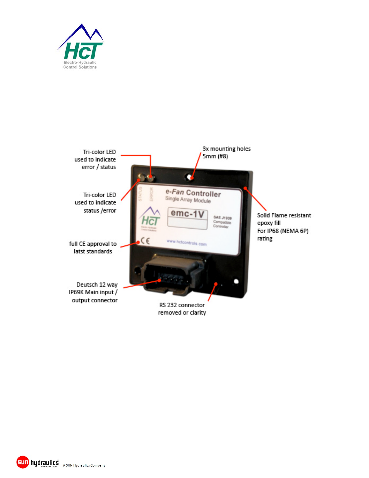
emc-1V Module Familiarity
e-Fan Cooling System Controllers
with J1939 Interface
Part No:- 021-00351 Rev 1.0 emc-1P & emc-1V e-Fan System Controller User Guide Page 11
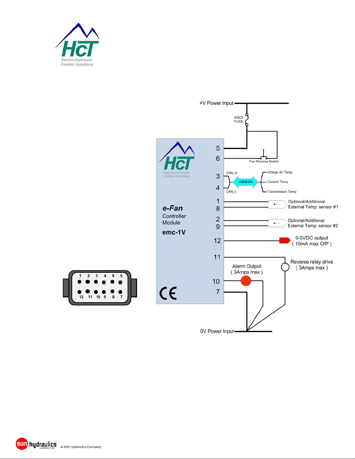
emc-1V Connection Information
NOTE:ControllerMUSThavein‐linefusefittedby
userinthe+VPowerInputforsystemprotection.
Pin 1 ....................... Sensor #1 +signal input
Pin 2 ....................... Sensor #2 +signal input
Pin 3 ....................... SAE J1939 HI input
Pin 4 ....................... SAE J1939 Low input
Pin 5 ....................... +Volts 9 to 32VDC power supply input
Pin 6 ....................... Reverse fan input (momentary)
Pin 7 ....................... Power supply return (GND)
Pin 8 ....................... Sensor #1 signal common
Pin 9 ....................... Sensor #2 signal common
Pin 10 ..................... Alarm out (3A max sourcing)
Pin 11 ..................... reverse out (3A max sourcing)
Pin 12 ..................... 0-5VDC e-fan out (10mA)
e-Fan Cooling System Controllers
with J1939 Interface
Part No:- 021-00351 Rev 1.0 emc-1P & emc-1V e-Fan System Controller User Guide Page 12
e-Fan Cooling System Controllers
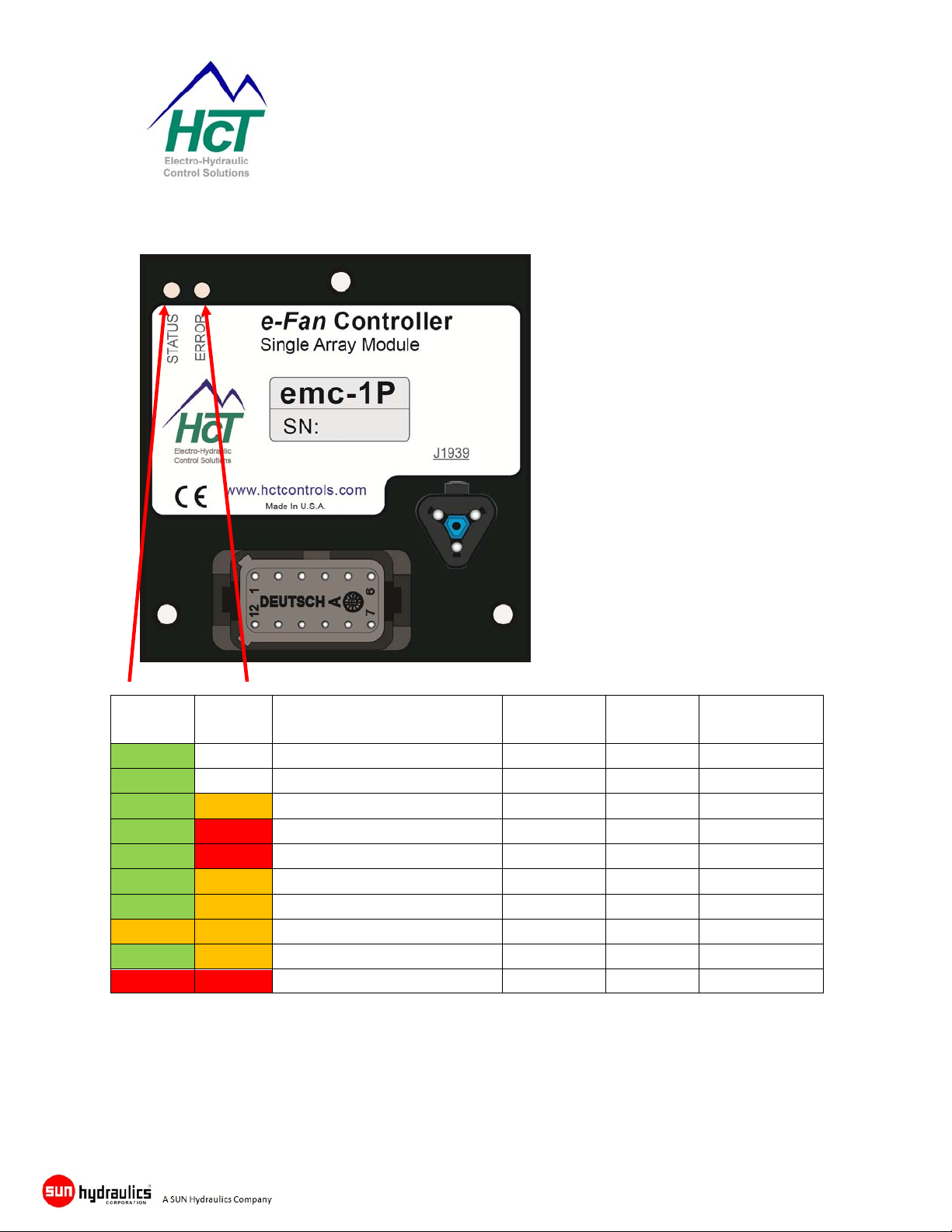
Error LED Code Descriptions for emc-1P & emc-1V
Status
Led
Static off
Flashing off
Static Static
Static Static
Static Flashing
Static Flashing
Static Flashing
Static Static
Flashing Flashing
Static Static
Note:*Fireinputisavailableontheemc‐1Ponly.
Error
LED
NormalOperation
ReverseCycle
FireInputon
Thermistoropen/short
FanDiag.Error
Alarmoutshort
Reverseoutshort
CanmessageTimeout
Coolingsystemover‐temp
Moduleovertemp
Description
AlarmOut FanOut
off normal normal
off revcycle cycleOn
on off off
on maximum normal
on retry normal
off normal normal
on normal off
on maximum normal
on maximum manualonly
on normal normal
with J1939 Interface
Reverse
operation
Part No:- 021-00351 Rev 1.0 emc-1P & emc-1V e-Fan System Controller User Guide Page 13

e-Fan Cooling System Controllers
with J1939 Interface
Module Connection Descriptions
Sensor #1 Input (emc-1P & emc-1V)
This input is designed to allow non SAE J1939 connected zones to be measured if required. The input
accepts a standard NTC thermistor. This input should be referenced to the Signal Ground (0V) on the
connector. The GUI is used to select / de-select and set-up the signal from this additional input and how it
effects the fan speed control. Note: Use Pin 8 for signal ground as the reference for temperature sensor
#1.
Sensor #2 Input (emc-1V only)
This input is designed to allow non SAE J1939 connected zones to be measured if required. The input
accepts a standard NTC thermistor. This input should be referenced to the Signal Ground (0V) on the
connector. The GUI is used to select / de-select and set-up the signal from this additional input and how it
effects the fan speed control. Note: Use Pin 9 for signal ground as the reference for temperature sensor
#2.
SAE J1939 High
This is the High side of the J1939 CAN Bus communication port. The cable used should be suitable for
this type of data connection. Reference, SAE J1939/01 3.1.8, J1939/11 and J1939/31, Please observe
proper Bus protocol including correct termination.
NOTE: The emc1P & emc-1V DO NOT have terminating resistors fitted – these must be system
supplied by others.
SAE J1939 Low
This is the Low side of the J1939 CAN Bus communication port. The cable used should be suitable for
this type of data connection. Reference, SAE J1939/01 3.1.8, J1939/11 and J1939/31, Please observe
proper Bus protocol including correct termination.
NOTE: The emc1P & emc-1V DO NOT have terminating resistors fitted – these must be system
supplied by others.
Power Supply Input
This terminal is the Main +Supply Voltage input on the controller. To provide the best possible noise
resistance and current capability, this input should be taken directly to battery Positive or the power
supply +V output using a large current capacity cable. An ACG 5, ATO 5 or compatible fuse should be
installed as close as practical to the originating power source.
Range – 9 to +32VDC
Note: Failure to install a proper fuse in-line with the controller will void the
warranty.
Part No:- 021-00351 Rev 1.0 emc-1P & emc-1V e-Fan System Controller User Guide Page 14

e-Fan Cooling System Controllers
with J1939 Interface
Fan Reverse Switch Input (Momentary contact)
This is a momentary signal input and only required that the input be pulled to +5V or Supply Power
Supply for approx. 500mS to initiate the reverse sequence settings, this input is debounced in the module
software to avoid false triggers.
This input may normally be referenced to chassis ground
Fire Detect Input: (emc-1P only)
Signal input must be pulled to +5V or Supply Power by the fire event. This will turn OFF the Fans.
This is not latched and will return to normal operation when off. (0V)
Connect to PWR common 0V (GND) if not used.
Ignition Input
Ignition input must be pulled to +5V or Supply Power to enable operation.
This is not latched, emc-1 will not be enabled when off.
Power Ground Input, (0V)
This terminal is the Main Power Ground or Power Common (0V) input on the controller. To provide the
best possible noise resistance and current capability, this input should be taken directly to battery
Negative or the power supply 0V (GND) output using a large current capacity cable. DO NOT use a
connection to chassis or false operation may occur.
Alarm Output
This output can SOURCE up to 3 amps at supply voltage and can be used to connect to an audio device
or light indicator to show the systems alarm condition. This output can be set active High, or active Low.
Output is reverse polarity and short circuit protected.
Reverse Indicator Output
This output can SOURCE up to 3 amps at supply voltage and can be used to connect to an indicator or
alarm to show reverse status. This is a normally OFF, output will go to supply voltage when energized.
Output is reverse polarity and short circuit protected.
NOTE:
The Alarm and Reverse Outputs, will source a small amount of current when OFF. The
currentavailableat32voltswouldbe~500uAand~200uAat12Volts.Thissmallamountof
currentshouldbeconsideredwhendrivinghighimpedanceinputsorhighefficiencyLEDs.
Proportional Output; The function of this pin is dependent on the model in use.
emc-1P
This is a proportional Pulse Width Modulation (PWM) output that vary between 0 to 100% and can source
up to 100mA and is intended to drive the command input of a ‘Smart’ electric fan that requires a low level
PWM input for control. The PWM frequency is adjustable from 33 to 500Hz through the GUI. This output
is reverse polarity, short and open circuit protected.
emc-1V
This is a proportional 0 to 5 Volt DC output that is capable of driving up to 10mA (or loads up to 100Ω)
and is intended to drive the command input typically seen on VFD converters. This output is reverse
polarity, short and open circuit protected.
Part No:- 021-00351 Rev 1.0 emc-1P & emc-1V e-Fan System Controller User Guide Page 15

e-Fan Cooling System Controllers
with J1939 Interface
Serial Communications
Controller monitoring, health checks, diagnostics and set-up can be accessed through the supplied GUI.
This program will operate on PC using a Windows® based operating system and is password protected
to maintain module parameter integrity by only allowing authorized users to access different levels of the
controller settings.
The interface is designed to be simple to use and follows the familiar Windows® menu format with drop
down option screens to select the various options available at the user level allowed.
Explanations of the screens are covered in detail, later in this guide.
Once the PC has been connected to a ‘live’ controller, and the GUI program started, a free
communications port will be allocated and communication with the GUI will begin.
Users running a computer without a 9 pin serial port MUST use one of the following approved
RS232/USB adaptors:
Manufacturer HCTPartNumber Notes
CommFront 108-00119
After communications have been established, the user will be presented with the initial information screen
that will give all the basic information needed to assess the health of the system.
Real time graphing is available to monitor a wide range of items (selectable from a drop down list) and for
remote diagnostics, a ‘Data Log’ button will start a Windows CSV file that can be used as a monitor for
comparison to other logged charts during the system’s life or can be E-mailed to an engineering source
for interpretation of system efficiency.
Passwords protect the settings of the module at all times and are needed to make any changes to the
operational parameters.
RS232 Serial Connection Cable: Part No- 999-10075 (see page 33 of this manual)
NOTE: The 4-pin shroud Weatherpack connector from the
controller has MALE pins, therefore the mating cable
needs to terminate in a Tower Weatherpack connector with
FEMALE pins.
CE certified
RoHS compliant
Part No:- 021-00351 Rev 1.0 emc-1P & emc-1V e-Fan System Controller User Guide Page 16

e-Fan Cooling System Controllers
with J1939 Interface
Loading the emc-1P or emc-1V GUI onto Host PC
Both controllers are set-up via a common GUI interface for ease of use.
GUI P/N: 023-00264
The PC Graphical User Interface (GUI) is a self-extracting and installing program that will reside on the
chosen host PC hard drive. It is recommended that the user allow the defaults to be used for easy future
update installation, but the option is given to allow the user to choose where the program should be
located.
It is NOT recommended that this program be run from a network as it needs access to certain files
available only in the Windows directories.
To start the installation process, insert the CD ROM or if this does not work, search for the “setup.exe”
Application and ‘run’.
System Requirements
Windows XP, Vista or Windows7
256MB or greater
Serial Port RS232 or USB Adapter
RS232 Serial Cable PN: 999-10075
Part No:- 021-00351 Rev 1.0 emc-1P & emc-1V e-Fan System Controller User Guide Page 17

Controller adjustments and Monitor
e-Fan Cooling System Controllers
with J1939 Interface
After program entries cycle power to ensure changes are accepted by the unit.
GUI Menu Options
File
-> Read file or Save File
The user has two simple options available:
1) Read settings from file.
This option allows the user to search for and find preciously saved settings files (*.DAT) and to load them
into a new controller or to reset a controller to a previous version e.t.c.
2) Save settings to file.
This option allows the user to save the current settings displayed on the GUI while connected to a
controller to a file name and destination of choice for retrieval at a later time.
These *.DAT files may also be E-mailed if required to other users to duplicate settings that may have
been optimized or changed.
Part No:- 021-00351 Rev 1.0 emc-1P & emc-1V e-Fan System Controller User Guide Page 18

-> Find Controller
e-Fan Cooling System Controllers
with J1939 Interface
Will search the com ports, find the controller, and read settings. Helpful if you have lost communication
and or want to do a clean read.
Password Protection
Enter Password
Password entry is started by clicking the ‘Password’ option in the top bar of the GUI screen.
This will open a box to enter the passwords.
Level 0) - NO Password
This allows the user to view the current operational, settings, and alarms. Operator may use the help
menu and log data. Cannot change settings or load new file.
Level 1) – OEM password (supplied with unit or contact HCT)
Access at this level gives the user full viewing as above and also allows changing of all of the system
settable parameters. This includes the resetting of the OEM password. Does NOT allow resetting of
highest values recorded. This is module warranty information for HCT.
Level 2) – High Country Tek Inc. (Safety Reset) Password
This level of password overrides all other password levels and allows HCT authorized personnel to
access the module and the software when required for factory settings.
Passwords are ‘cAsE
SeNsitivE’ so ensure
you have the ‘Caps
Lock’ off if required.
Part No:- 021-00351 Rev 1.0 emc-1P & emc-1V e-Fan System Controller User Guide Page 19

Menu Option
->Help
Help
e-Fan Cooling System Controllers
with J1939 Interface
View Help
This option directs you to emc-1 manual that is part of the installation package. You may add your own
docs by adding word.doc or other .pdf files to the same folder. (c:\HCT Products\Fan Drives\emc-1)
Print Parameter
This will print all settings to your PC default printer. Or print to a text file, tab delimited. The text file may
be viewed with Notepad, Word, or Excel. You could also set your default printer to ‘Adobe PDF’ for
storage on your PC.
->Quit or EXIT
This will insure that the unit is not left in the manual mode, it will then close the GUI and release
the communication port for future use.
Part No:- 021-00351 Rev 1.0 emc-1P & emc-1V e-Fan System Controller User Guide Page 20
e-Fan Cooling System Controllers
with J1939 Interface
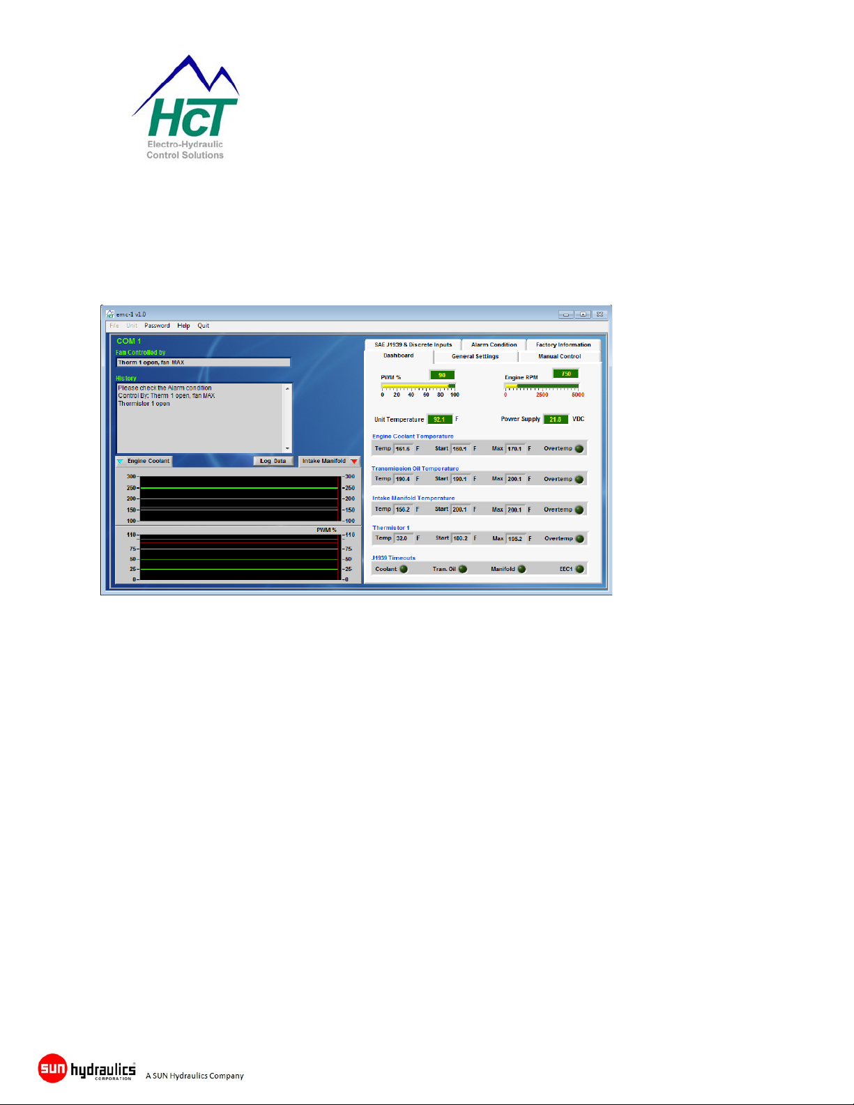
GUI software – Main screen (Dashboard)
The software has been designed such that there is NO nesting of menus so that it is easy to navigate
around the different screens without getting lost or having multiple windows open at any one time. The
five main screens are available via ‘Click Tabs’ from the ‘Dashboard’ and are:
The ‘Dashboard’ tab provides a quick user overview of the controller operation, system status and
condition of the J1939 data Bus. Error indicators change from Green (OK) to Red (error or alarm) with an
over temperature or a J1939 message timeout.
Fan Controlled by:
Displays what attribute is currently controlling the Fan.
History
Continuous updates of all changes in module operation as they happen, new changes are reported at the
top.
Graphs
There are two graphs displaying Temperature and PWM%. You may select which two Temperatures that
you want to monitor.
Each signal displayed will have a color coded individual scale on the ‘Y’ axis.
The History and Graphs are providing vital information on the operational status of the emc-1.
Part No:- 021-00351 Rev 1.0 emc-1P & emc-1V e-Fan System Controller User Guide Page 21

e-Fan Cooling System Controllers
with J1939 Interface
Data Logging
Start a data log by clicking on this button, data logging will continue until it is turned off by using the same
button now labeled “Logging Data”
Module Input Voltage
Module Internal Temperature
Proportional Valve Current
Thermistor #1 Temp I/P ( Actual )
Thermistor #2 Temp I/P ( Actual )
J1939 Coolant Temperature ( Actual )
J1939 Inlet Manifold Temperature ( Actual )
J1939 Transmission oil Temperature ( Actual
Note: you may also right click on the graph at any time to capture a window in spreadsheet format.
The file type will be saves as tab delimited file and may be viewed by any text editor or copied
directly into Excel for examination.
The user should be cautious when using this LOG function as the files can become very large if
logging is left to continue for long periods, making the files difficult to read and manage.
Experience has shown us that several smaller logs over adjacent periods are easier to
manipulate and view as graphical data.
Part No:- 021-00351 Rev 1.0 emc-1P & emc-1V e-Fan System Controller User Guide Page 22

General Settings
Selection Tab -> General Settings
e-Fan Cooling System Controllers
with J1939 Interface
On each tab changes must be ‘Applied’ to take effect. Cancel will restore values.
Unit Settings
Unit Disabled
The controller is shipped in a disabled state and should be enabled by the OEM or user by using the GUI.
Once this button is selected, the date from the enabling PC is taken and used as the ‘Born Date’ when
warranty starts.
Alarm Active High
This sets the default state of the alarm output to allow normally OFF or normally ON devices to be driven.
When enabled, the output is HIGH when alarm condition exists and LOW with NO alarm condition.
Retry Alarm and Reverse Shorts
If not checked and a short is detected on the Alarm output or the Reverse Indicator output, the software
will stop driving that circuit until a power cycle. Thus preventing damage to external hardware from high
current or overheating. This does not affect fan control.
Temperature Units
This setting selects either degrees Fahrenheit or degrees Centigrade and ripples through all the settings
that deal with temperature.
Part No:- 021-00351 Rev 1.0 emc-1P & emc-1V e-Fan System Controller User Guide Page 23

e-Fan Cooling System Controllers
with J1939 Interface
Output Settings
Refer to the requirements set by the fan manufacture for the following 3 adjustments:
1. Minimum PWM% (0-100%) output
2. Maximum PWM% (0-100%) output
3. PWM Freq ( 33-500Hz): This is the ‘dither’ or operating frequency for the PWM% output.
Minimum RPM (50-4000RPM)
This value is the engine RPM needed before the fan controller will start to operate above the minimum
system speed set by the motor pressure drop – this reduces the load on the starter motor.
NOTE: Information for this feature is taken from the J1939 Bus and cannot be used if not connected.
Start Up Delay (0-30 seconds)
Delay action is only triggered once when power is first applied to the module i.e. at key ON engine start
time. This feature is designed to reduce the load on the starter motor by holding off fan operation until the
time set has expired.
Input 0 to 30 seconds
Ramp UP & Down (0.5-30 seconds)
This will affect the output rate of change. These should be set to give smooth operation but not too long
or performance will be affected by slowing down fan speed response.
Auto Reverse Settings
Dwell Time (0-60 seconds)
This is the time that the controller allows for the fan to get to minimum speed before changing direction
when entering or leaving the reverse mode.
Time in Reverse (0-120 seconds)
Sets the duration for fan reverse operation.
Auto Reverse Time (1-1440min)
Sets the wait period between fan reverse cycles.
Disable Auto Reverse
When checked this will set the Auto Reverse Time to 0.0 and not allow the use of the setting.
Note: If J1939 messages are enabled, the RPM must be above minimum RPM setting for fans to work in
the forward or reverse direction.
With an over-temp alarm active, only the manual input will start a Reverse Cycle. Auto Reverse is
disabled.
Part No:- 021-00351 Rev 1.0 emc-1P & emc-1V e-Fan System Controller User Guide Page 24

Input Settings
Selection Tab -> SAE J1939 & Discrete Inputs
e-Fan Cooling System Controllers
with J1939 Interface
Settings do not take effect until Applied
Enable J1939
This option MUST be clicked if the unit is to understand the J19349 Bus information. If this button is NOT
clicked, all J1939 features are disabled in the controller.
Note: If J1939 messages are enabled, the RPM must be above minimum RPM setting for fans to work in
the forward or reverse direction.
Temperature settings
The emc-1 has 3 J1939 Bus messages and Thermistor inputs that can be individually enabled or disabled
as required.
Engine Coolant temperature at PGN 65262, SPN 109
Transmission Oil temperature at PGN 65272, SPN 177
Intake Manifold temperature at PGN 65270, SPN 105
Output PWM% to the fan is controlled between ‘Fan Start Temperature’ and ‘Fan max temperature’
and is a linear line between these two set values.
Fan Fault Condition
Set this for the fault condition that your fan will produce as the diagnostic input for Fan 1 or Fan 2.
Depending on the fan type it will either do nothing, Open, or will drive the input Low or High to indicate a
fault.
Set to Disabled if not used.
Part No:- 021-00351 Rev 1.0 emc-1P & emc-1V e-Fan System Controller User Guide Page 25

Sensor setup
e-Fan Cooling System Controllers
with J1939 Interface
Allows for a switch input or a thermistor input and name
for either. Name is useful in data logging and on the
Dashboard monitor.
As a Thermistor input:
Check the Thermistor box, then select profile type from
pull down menu, and enter the Start, Maximum, and
Alarm temperature values, then Apply Changes.
As a Switch input:
Check the Switch box, then select Active High or Active
Low for the input. Enter a name if desired, then Apply
Changes
Apply Changes will save to the unit and close this
window. Or Cancel Changes to close window without
applying.
Part No:- 021-00351 Rev 1.0 emc-1P & emc-1V e-Fan System Controller User Guide Page 26

Error Information Log
Selection Tab -> Alarm Condition
e-Fan Cooling System Controllers
with J1939 Interface
This page shows the user information that will help to track and where necessary, fix intermittent opens
and short circuits on any of the wires used to connect to the sensors, switches or the coils in the system.
The program shows where the error has been seen, even if the error has cleared itself.
The information can be cleared by the user with the appropriate password level by clicking the ‘Reset’
button in the Opens and Shorts section.
Highest Readings are stored permanently in the modules memory and cannot be reset by the user.
These are the maximum values seen on several key areas including the module health, and are only
overwritten by higher values.
Part No:- 021-00351 Rev 1.0 emc-1P & emc-1V e-Fan System Controller User Guide Page 27
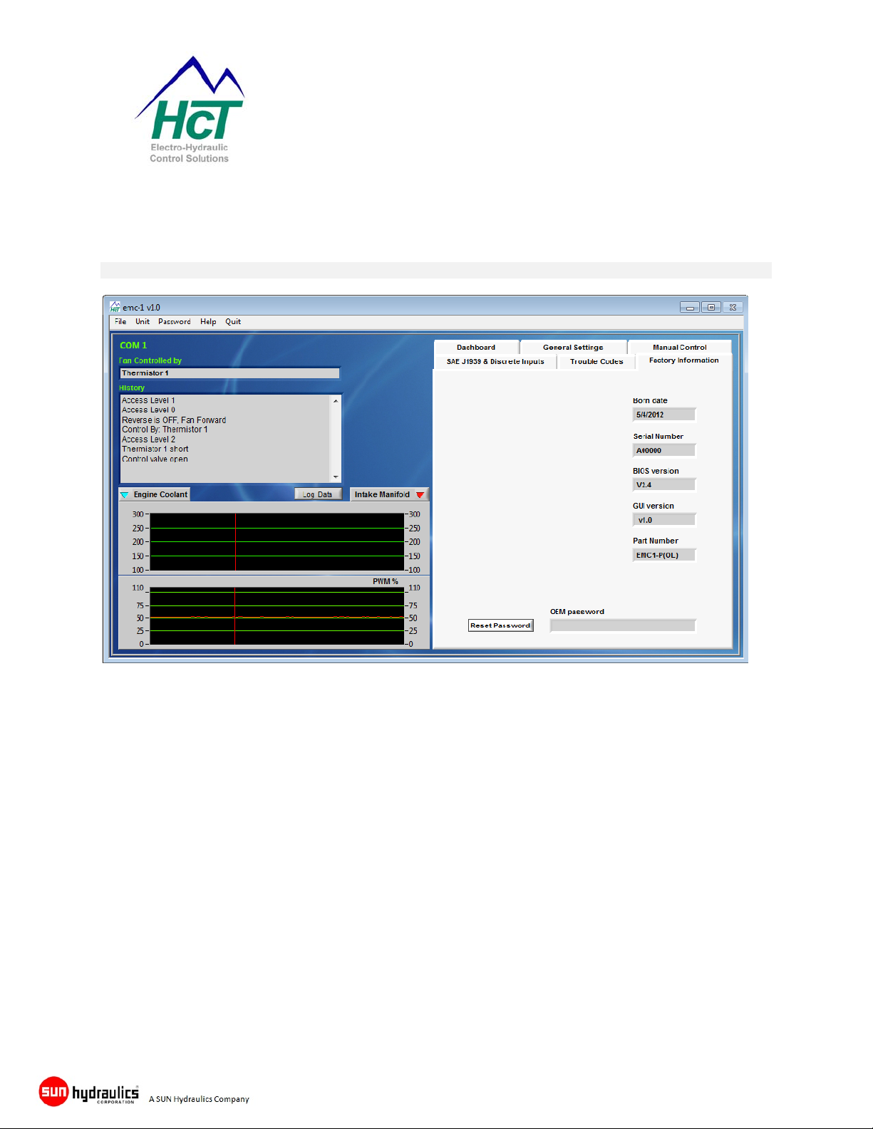
Factory Information
Selection Tab -> Factory Information
e-Fan Cooling System Controllers
with J1939 Interface
This page allows the user to view information concerning the controller serial number, GUI Part number,
BIOS and Graphical user Interface (GUI) software versions as well as the ‘Born Date,’ which is taken from
the local PC used to activate the module.
This information should always be available when requesting support so that HCT personnel
know the level of controller with which you are working.
Part No:- 021-00351 Rev 1.0 emc-1P & emc-1V e-Fan System Controller User Guide Page 28

Temperature Sensor Information
HCT P/N: 206-00083, Wet fluid temperature sensor.
13.10
56.1
24.2 REF
Housing Type: Delphi Unique
Typical supply voltage: +5VDC
Dissi pation Con stant*: 24m W/°C
The rmal Tim e Constan t**: 17.5 to 23.5 seconds
Temperature range: -40 to +150 ºC
( operational )
NEMA/IP Rating: NEMA 6P/68
8.30 DIA
13.00
Con t act HCT cu st omer se rvice for mo re
sensor options and information
HCT P/N: 206-00084, Dry fluid temperature sensor.
Housing Type: Delphi Unique
Typical supply voltage: +5VDC
Dissipation Constant*: 18m W/°C
Thermal Time Constant**: 60seconds
Temperature range: -40 to +150 ºC
( operational )
NEMA/IP Rati ng: NEMA 6P/6 8
Main I/O connector & Accessories
e-Fan Cooling System Controllers
with J1939 Interface
Sensor Body: Brass
Connector Body: PBT 30%
Glass Filled
Hex Size: 18.9mm / 3/4”
Thread Size: 3/8’ - 18 NPTF
Thread Sealant: GM09985473
Sealing Pressure: 145kPa
Installation Torque: 20Nm
Overall Weight: 40g
Sensor Body: PEI ( polyetherim ide )
30% Glass Filled
Connector Body: PBT 30% Glass Filled
Hex Size: 18.9mm / 3/4”
Thread Size: 3/8’ - 18 NPTF
Thread Sealant: GM09985490
Sealing Pressure: 145kPa
Installation Torque: 10.8 - 16.3 Nm
Overall Weight: 13.2g
Mating connector Parts information: Complete harnesses and connector kits can be supplied by HCT.
Please contact customer service for information.
System Accessories for emc-1P and emc-1V:
Item Description: HCT P/No:
SAE J1939 connector kit for the emc-1P 999 - 10244
RS232 Communications Cable - Weatherpack 999 - 10075
emc-1Main Mating I/O connector Kit 999 - 10155
emc -1Graphical User Interface ( GUI ) replacement Disk 023 – 00264
emc -1Operating Manual 021 – 00351 (see website for latest version)
Part No:- 021-00351 Rev 1.0 emc-1P & emc-1V e-Fan System Controller User Guide Page 29

e-Fan Cooling System Controllers
with J1939 Interface
On Site Testing
If the set up procedure does not achieve the desired results, double check the wiring and perform the
following tests. Record the test results.
Tools Required:
A PC running Windows XP, Vista, or Windows7 and the correct emc-1 software are required for initial setup, programming or observation of the controllers operation through the RS232 port (directly or via a USB
to serial converter cable).
The PC can also be used for uploading the configured program to new emc-1 modules for upgrades.
A battery operated multi meter is always a good idea for measuring and confirming analog signals and an
oscilloscope would be useful for looking at fast moving or digital signals on the system.
Check the Power input: (9-32V)
If the supply voltage is below 9VDC, there is a risk of:
a) Module shutting down,
b) Module continuously trying to reset or
c) Low drive current to valves.
If the supply voltage is more than 32 VDC there is a risk of:
a) Blown in-line AGC5 fuse
b) Module shutting down.
c) Fan damage due to excessive drive voltage.
Check the Control Inputs:
Verify that any analog control inputs are the correct polarity and are hooked up correctly and to the
correct module terminals by monitoring their status with the emc-1software or testing with a voltmeter or
oscilloscope.
Ensure the J1939 Bus is terminated correctly (120 ohm resistors) and that the engine is running to ensure
good data.
Ensure that any external control or command inputs have their respective sources 0V or GND connected
to the modules power supply 0V or GND terminal.
Verify That Alarm or Reverse Indicator Loads are Not Shorted:
Disconnect the wires going to the terminals and measure the resistance between the wires. Verify it is in
the expected Ohmic range for the type and voltage of load being driven. Verify that there is no voltage
with respect to ground generated by the load and wiring.
Part No:- 021-00351 Rev 1.0 emc-1P & emc-1V e-Fan System Controller User Guide Page 30

e-Fan Cooling System Controllers
with J1939 Interface
If the e-Fan Operation is Erratic:
Electrical interference on the control lines can cause erratic behavior if it is strong enough. Observe the
control inputs on the PC. If noise greater than a few percent is noticed on an unchanging PULSE IN or
COMMAND IN input, or if the digital inputs are toggling, try changing the routing of the control wires to
see if the problem changes.
Power supply interference or brown outs can also cause erratic behavior. Observe the power supply on
the graph on the PC. If large dips are noticed, test for a poor supply by running the card off its own fully
charged battery.
Further Information:
Visit the HCT website (www.hctcontrols.com)
for additional documentation and assistance.
Part No:- 021-00351 Rev 1.0 emc-1P & emc-1V e-Fan System Controller User Guide Page 31
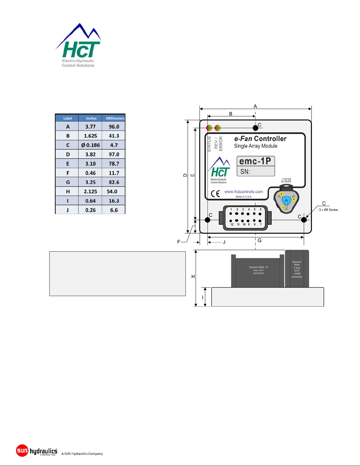
emc-1P & emc-1V Dimensional Information
Notes:
Mount controller as shown or with connector
facing down to avoid surface debris collecting.
Unit weight is approx. 250 grams
RS232 cable removed for clarity
RS232 cable is approx 6” long
e-Fan Cooling System Controllers
with J1939 Interface
Housing Type ........................... High Country Tek unique ‘encapsulated’ block
Housing Material ...................... None, solid, flameproof epoxy resin block
Housing Color .......................... Black / dark Grey
Surface Finish .......................... Smooth Gloss
Housing Thickness .................. 16.5mm (main module) ~41.5mm incl. Connectors
Unit Size.................................... See above size detail drawings
Unit Weight ............................... Approx. 250 grams (including Encapsulation material)
Wire Entry ................................. Industry standard 12-way Deutsch, sealed connector
Encapsulation .......................... Flame Resistant, Black, Two-Part Epoxy Resin
Mounting................................... Via through holed ( 3 ) suitable for No. 8 ( 5mm ) screw
Temperature Range ................. - 40 to +85 degrees Centigrade (operational)
Part No:- 021-00351 Rev 1.0 emc-1P & emc-1V e-Fan System Controller User Guide Page 32
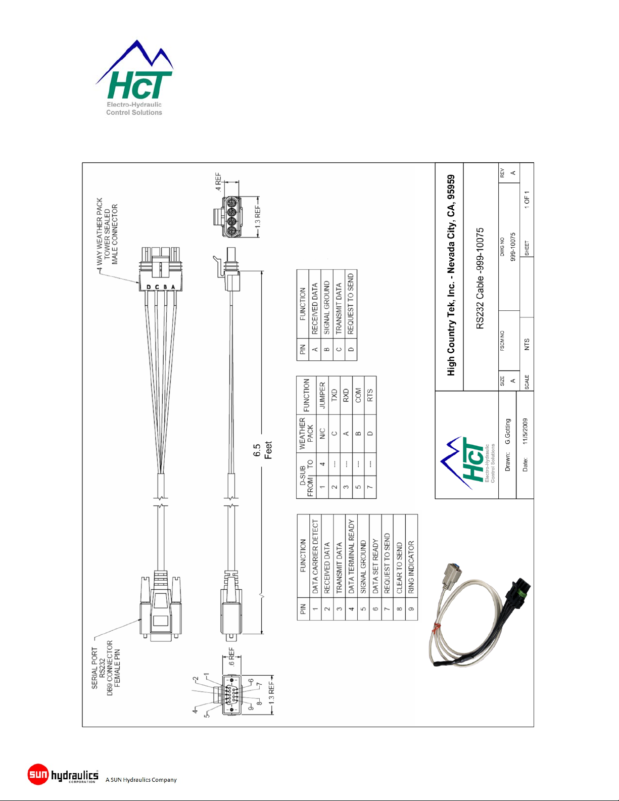
RS232 Communication Cable
e-Fan Cooling System Controllers
with J1939 Interface
Part No:- 021-00351 Rev 1.0 emc-1P & emc-1V e-Fan System Controller User Guide Page 33

Mining & Exploration
Agriculture
Cranes & lifts
Refuse & Re-cycling
Construction
Off-Road vehicles
Forestry, Wood & Pulp
Reclamation & Salvage
Oil Field & Sands
Demolition Equipment
Cooling Solutions
Military Apparatus
Specialty Use
Remote Control
Power Generation
Emission Controls
Integrated Drivers
Valve & Pump Controls
e-Fan Cooling System Controllers
with J1939 Interface
Electronic Control Solutions for the Global Fluid Power Industry
HCT Product Sales and Support:
For a full list of authorized distributors worldwide, please visit:
www.hctcontrols.com/distributors/index.htm
Need more information ?
To discuss anything in this brochure, order product, get
price and delivery or schedule an application discussion
meeting, please contact your nearest HCT distributor who
will be pleased to help you.
www.hctcontrols.com
Visit our website for the latest product releases, application
ideas, literature and software downloads.
Copyright © High Country Tek, Inc. - 2012
Note: T his guide is intended for suggestion onl y and may contain mist akes and print ing errors. Users should check calcul ations and confirm pa rts selection wi ll meet system re quirements whil e complying with cust omer specific or local and state saf ety requirements at all times.
Part No:- 021-00351 Rev 1.0 emc-1P & emc-1V e-Fan System Controller User Guide Page 34
HCT and accepts NO liability for technical mistakes or printing errors, or their consequences
High Country Tek, Inc.
208 Gold Flat Court
Nevada City, CA, 95959
Tel: (1) 530 265 3236
Fax:(1) 530 265 3275
 Loading...