

HCT DVC750 User Manual
Instruction, Installation and Operation Guide for:
DVC750 Product Manual
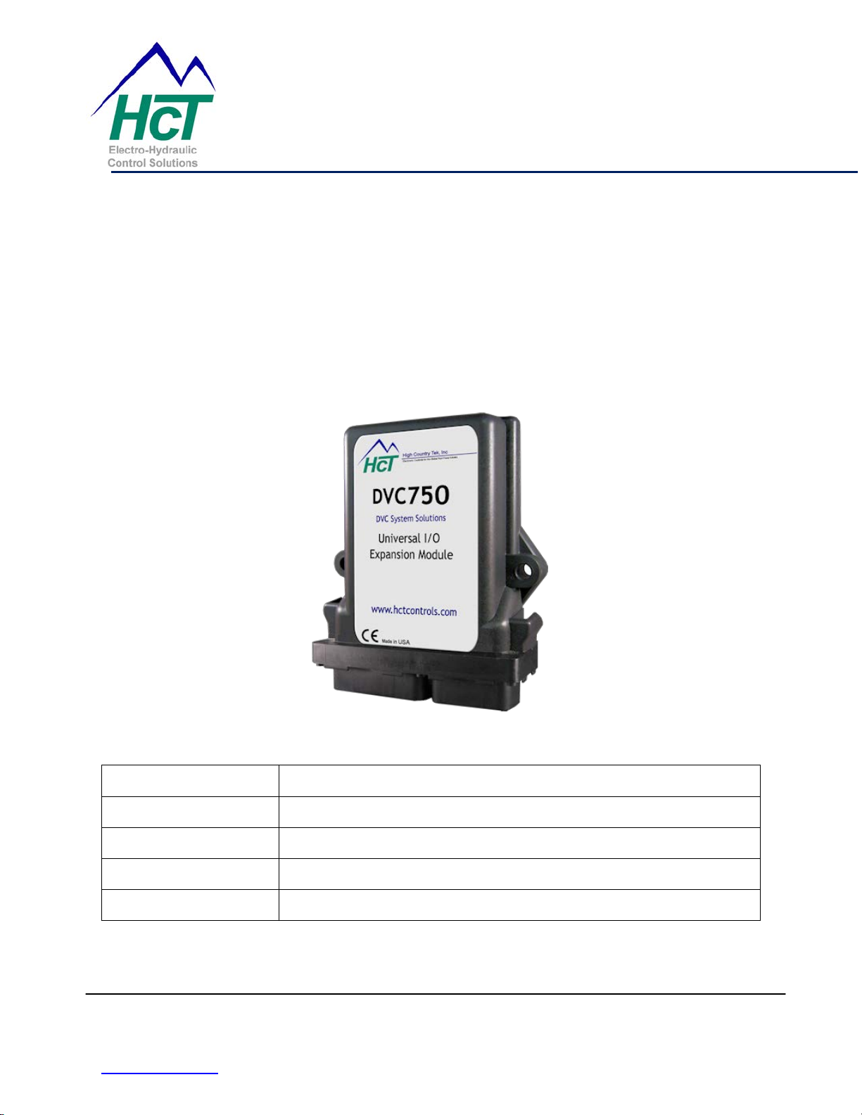
DVC750, Universal I/O Module
Document Number: 021-00196
Document Revision: A
Document Issue Date: 4/28/2011
Document Creator: J. Clark
Document Creation Date: 4/21/2011
High Country Tek, Inc.
208 Gold Flat Court
Nevada City, CA, 95959.
Tel:- (1) 530 265 3236
www.hctcontrols.com 021-00196_Rev_A-DVC750_User_Guide
1/9

DVC750 Product Manual
DESCRIPTION
The DVC750 expansion module is a multi-I/O unit designed to oper a te in conjunction
with a DVC10 master controller module. The large number of additional, individually
configurable inputs and outputs make it ideal for more complex applications that need
additional operator interface and multi-coil drive capabilities. Several +5VDC regulated
user voltages are also provided at the connector to supply power to external sensors or
local command sources. To aide programming and make wiring simplified, the input and
output groups are the same as the DVC710. The DVC750 communicates with the
DVC710 controller through the HCT CAN Bus (high-speed communication) and utilizes
a separate RS-232 por t for prog r a mming , upd ates , mo ni tor ing, diagnostics and feat ur es
such as setting the MAC ID (node) number e.t.c. The controller is packaged in the
standard DVC series enclosure and fully encapsulated to withstand the fluid power
harsh operating environments.
TECHNICAL DATA
Analog/Pulse Inputs – Qty (2)
These inputs can be configured as analog (0 to +5Vdc) or pulse (0 to +5Vdc) inputs. A
+5Vdc Reference is supplied with each input for an external sensor.
PROGRAMMABLE MODES
A. Analog (0 to +5Vdc)
B. Pulse (0 to +5Vdc)
1 Pulse Timeout – sets a flag if a pulse has not been detected for a certain
amount of time.
2 Pulses Per Rev – used for calculating RPM.
Note - The maximum pulse rate for each input is 7 kHz.
C. Counter Mode - For Counter pulse inputs, setup the Min and Max counts under
Count Limits. The output value will be a percent of Min to Max count. The counter
value may be read or set/reset by the application. The counter is incremented on
every falling edge of the pulse input.
JOYSTICK/VOLTAGE CONFIGURATION OPTIONS
A. Enable Center - sets up upper and lower configuration for single axis joystick.
B. Deadband – Sets the % of deadband at center .
High Country Tek, Inc.
208 Gold Flat Court
Nevada City, CA, 95959.
Tel:- (1) 530 265 3236
www.hctcontrols.com 021-00196_Rev_A-DVC750_User_Guide
2/9

DVC750 Product Manual
C. Voltage Calibration – Setting for the actual voltage received at the input (Min,
Center and Max).
D. Voltage Limits – sets the Min a Max limits of the input. A flag is set when these
limits are met. This feature det ects unwanted conditions so that the controller can
be safely programmed to a default condition
Note – The input will go high if the input is open (no connection).
E. Invert Output – Simply inverts the output control with respect to the input
command.
F. Enable Ramps – applies ramping to the input.
G. Scaling – sets the offset and gain to the input which results to meaningful data
displayed in the Loader Monitor.
ANALOG INPUTS – Qty (4)
The Analog inputs have a range of 0 to +5Vdc. A +5Vdc Reference is supplied with
each input for an external se nsor .
JOYSTICK/VOLTAGE CONFIGURATION OPTIONS
A. Enable Center - sets up upper and lower configuration for single axis joystick.
B. Deadband – Sets the % of deadba nd at center.
C. Voltage Calibration – Setting for the actual voltage received at the input (Min,
Center and Max).
D. Voltage Limits – sets the Min a Max limits of the input. A flag is set when these
limits are met. This feature detects unwanted conditions so that the controller can
be safely programmed to a default condition
Note – The input will go high if the input is open (no connection).
E. Invert Output – Simply inverts the output control with respect to the input
command.
F. Enable Ramps – applies ramping to the input.
G. Scaling – sets the offset and gain to the input which results to meaningful data
displayed in the Loader Monitor.
DIGITAL INPUTS – QTY (8)
INPUTS 1 – 8 (SINKING)
A. These inputs are sinking (need +5Vdc to +32Vdc to cause the input to switch
change states).
High Country Tek, Inc.
208 Gold Flat Court
Nevada City, CA, 95959.
Tel:- (1) 530 265 3236
www.hctcontrols.com 021-00196_Rev_A-DVC750_User_Guide
3/9
 Loading...