

HCL HCMDLWBT21, HCMDLWBN21 Service Manual
15.6" LCD Color Monitor HCL HCMDLWBT21&HCMDLWBN21
1
Service
Service
Service
Horizontal Frequency
30-60 kHz
TABLE OF CONTENTS
Description
Page Description Page
SAFETY NOTICE
ANY PERSON ATTEMPTING TO SERVICE THIS CHASSIS MUST FAMILIARIZE HIMSELF WITH THE CHASSIS
AND BE AWARE OF THE NECESSARY SAFETY PRECAUTIONS TO BE USED WHEN SERVICING
ELECTRONIC EQUIPMENT CONTAINING HIGH VOLTAGES.
Table Of Contents…………………………………………...1
Revision List………………………………………………....2
Important Safety Notice.…….........................……...... 3
1. Monitor Specification..............................…………........4
2. LCD Monitor Description…………………………….......5
3. Operation Instructions....................................…...........6
3.1. General Instructions...........................…....................6
3.2. Control Buttons..………………………….…...............6
3.3 Adjusting the Picture.................................…..............7
4. Input/Output Specification............……………............10
4.1. Input Signal Connector............………….................10
4.2. Factory Preset Display Modes......…..................10
4.3. Panel Specification.....………………..................11
5. Block Diagram….........................................................13
5.1 Software Flow Chart………………………….……….13
5.2.Electrical Block Diagram…………………….......15
6. Schematic……………..............................................17
6.1 Main Board....……….............................................17
6.2 Power Board………………………………………....22
6.3 Key Board…………………...….……………………24
7. PCB Layout..………….............................................25
7.1. Main Board………................................................25
7.2. Power Board….....................................................26
7.3. Key Board….........................................................27
8. Maintainability………...............................................29
8.1.Equipments and Tools Requirement......................29
8.2.Trouble Shooting………........................................30
9. White-Balance, Luminance adjustment………..…...36
10. Monitor Exploded View…………………….…........38
11. BOM List…............................................................39
12. Different Parts List…………………………….…….61
CAUTION: USE A SEPARATE ISOLATION TRANSFOMER FOR THIS UNIT WHEN SERVICING
15.6" LCD Color Monitor HCL HCMDLWBT21&HCMDLWBN21
2
Revision List
Version Date Revision History Customer Model TPV Model Name
A00 Sep.-4-08 Initial release T68MRDDCWXKLNN
T682RDDCWXKCNN
T683RDDCWXKCNN
A01 Oct.-21-08 Add new BOM
HCMDLWBT21
T68VRDDCWXKLNN
T67MRDNCWXLHNN
T67MRDNCWXKLNN
A00 Nov.-12-08 Initial release HCMDLWBN21
T68VRDNCWXLHNN

15.6" LCD Color Monitor HCL HCMDLWBT21&HCMDLWBN21
3
Important Safety Notice
Proper service and repair is important to the safe, reliable operation of all AOC Company Equipment. The service
procedures recommended by AOC and described in this service manual are effective methods of performing service
operations. Some of these service operations require the use of tools specially designed for the purpose. The
special tools should be used when and as recommended.
It is important to note that this manual contains various CAUTIONS and NOTICES which should be carefully read in
order to minimize the risk of personal injury to service personnel. The possibility exists that improper service
methods may damage the equipment. It is also important to understand that these CAUTIONS and NOTICES ARE
NOT EXHAUSTIVE. AOC could not possibly know, evaluate and advise the service trade of all conceivable ways in
which service might be done or of the possible hazardous consequences of each way. Consequently, AOC has not
undertaken any such broad evaluation. Accordingly, a servicer who uses a service procedure or tool which is not
recommended by AOC must first satisfy himself thoroughly that neither his safety nor the safe operation of the
equipment will be jeopardized by the service method selected.
Hereafter throughout this manual, AOC Company will be referred to as AOC.
WARNING
Use of substitute replacement parts, which do not have the same, specified safety characteristics may create shock,
fire, or other hazards.
Under no circumstances should the original design be modified or altered without written permission from AOC.
AOC assumes no liability, express or implied, arising out of any unauthorized modification of design.
Servicer assumes all liability.
FOR PRODUCTS CONTAINING LASER:
DANGER-Invisible laser radiation when open AVOID DIRECT EXPOSURE TO BEAM.
CAUTION-Use of controls or adjustments or performance of procedures other than those specified herein may
result in hazardous radiation exposure.
CAUTION -The use of optical instruments with this product will increase eye hazard.
TO ENSURE THE CONTINUED RELIABILITY OF THIS PRODUCT, USE ONLY ORIGINAL MANUFACTURER'S
REPLACEMENT PARTS, WHICH ARE LISTED WITH THEIR PART NUMBERS IN THE PARTS LIST SECTION OF
THIS SERVICE MANUAL.
Take care during handling the LCD module with backlight unit
-Must mount the module using mounting holes arranged in four corners.
-Do not press on the panel, edge of the frame strongly or electric shock as this will result in damage to the screen.
-Do not scratch or press on the panel with any sharp objects, such as pencil or pen as this may result in damage to
the panel.
-Protect the module from the ESD as it may damage the electronic circuit (C-MOS).
-Make certain that treatment person’s body is grounded through wristband.
-Do not leave the module in high temperature and in areas of high humidity for a long time.
-Avoid contact with water as it may a short circuit within the module.
-If the surface of panel becomes dirty, please wipe it off with a soft material. (Cleaning with a dirty or rough cloth may
damage the panel.)
15.6" LCD Color Monitor HCL HCMDLWBT21&HCMDLWBN21
4
1. Monitor Specification
Driving system TFT Color LCD
Viewable Image Size 395mm diagonal
Pixel pitch
0.252mm(H) x 0.252mm(V)
Dot Clock
85.5MHz(typ)
LCD Panel
Display Colors 16.7M Colors
Video R, G, B Analog Interface
Separate Sync. H/V TTL
H-Frequency
30 – 60 kHz
Horizontal scan Size(Maximum) 344.3mm
V-Frequency
55 - 75 Hz
Input
Vertical scan Size(Maximum) 193.5mm
Highest preset resolution 1360 x 768 (60 Hz)
Regulatory Compliance FCC
Plug & Play VESA DDC2BTM
ON Mode ≤28W (For 2 CCFL)
Power
Consumption
OFF Mode ≤1 W
Input Connector 15-pin D-Sub
Input Video Signal Analog: 0. 7Vp-p(standard), 75 OHM, Positive
Power Source 100~240V AC,50~60Hz
Height (with base)
304.4 mm
Width
376.3 mm
Dimension
Depth
190 mm
Weight (monitor only)
2.7 kg
Temperature: Operating 5° to 35°
Temperature: Storage -20° to 60°C
Environmental Considerations
Humidity: Operating 10% to 85%
15.6" LCD Color Monitor HCL HCMDLWBT21&HCMDLWBN21
5
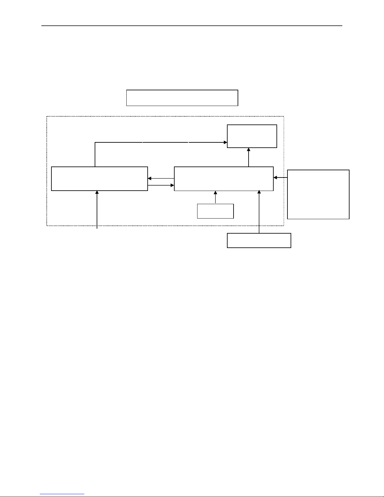
2. LCD Monitor Description
The LCD Monitor will contain main board, power board, key board which house the flat panel control logic,
brightness control logic and DDC.
The power board will provide AC to DC Inverter voltage to drive the backlight of panel and the main board chips
each voltage.
Video signal, DDC
Power Board
Flat Panel and
CCFL backlight
Main Board
RS232 Connector
For white balance
adjustment in
factory mode
HOST Computer
CCFT Drive.
AC-IN
100V~240V
Monitor Block Diagram
Key board
15.6" LCD Color Monitor HCL HCMDLWBT21&HCMDLWBN21
6
3. Operation Instructions
3.1 General Instructions
Press the power button to turn the monitor on or off. The other control buttons are located at front panel of the
monitor. By changing these settings, the picture can be adjusted to your personal preferences.
• The power cord should be connected.
• Connect the Signal cable from the monitor to the VGA card.
• Press the power button to turn on the monitor position. The power indicator will light up.
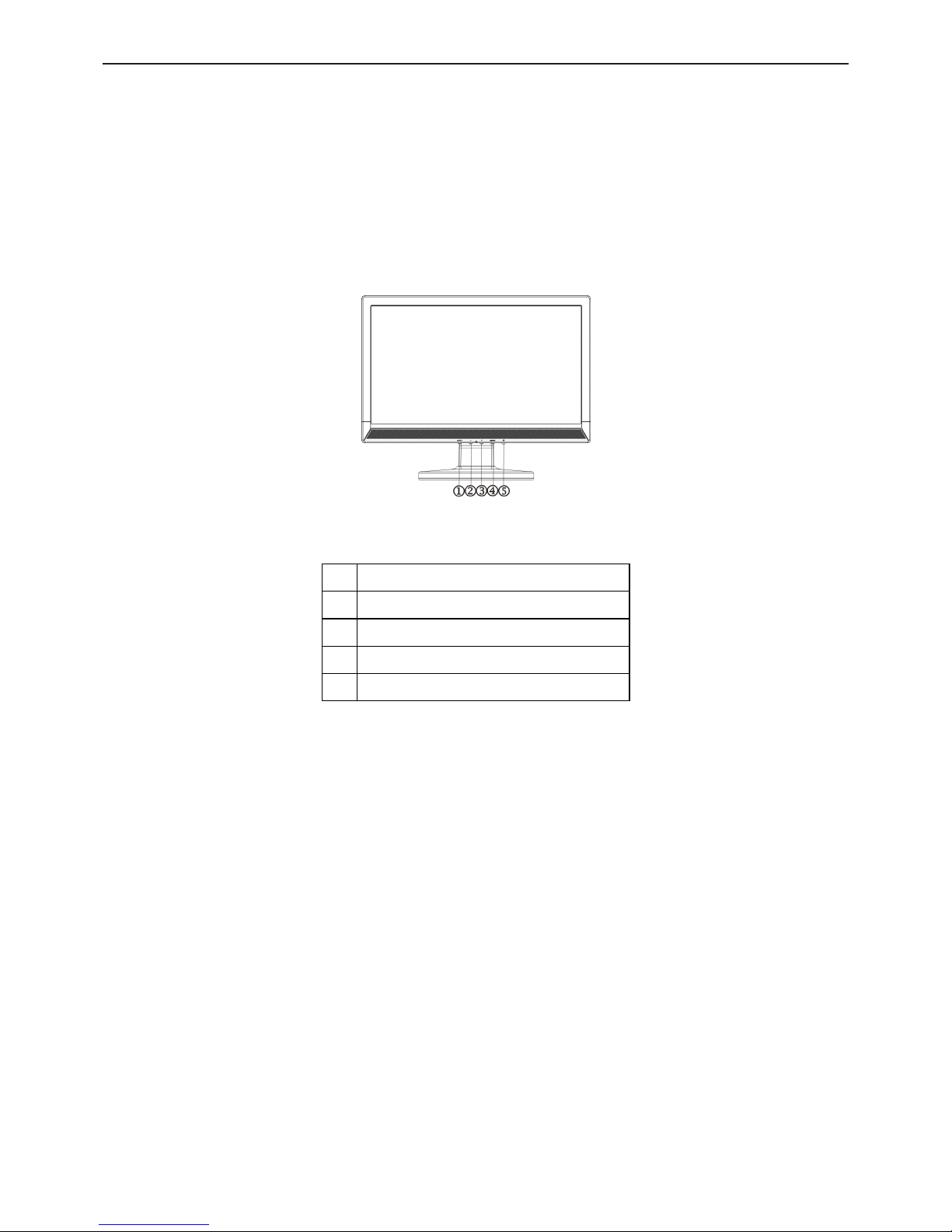
3.2 Control Buttons
External Control Button
1. Auto Config / Exit
2. -/ECO
3. +/DCR
4. MENU / ENTER
5. Power Button
Front Panel Control
• Power Button /Power Indicator:
Press this button to switch ON/OFF of monitor’s power.
Green — Power On mode.
Orange — Power saving mode.
• MENU / ENTER :
Active OSD menu or function adjust confirm or Exit OSD menu when in volume OSD status.
• Contrast :
Adjust contrast or adjust function.
• Brightness :
Adjust brightness or adjust function.
• Auto Adjust button / Exit:
1. When OSD menu is in active status, this button will act as EXIT-KEY (EXIT OSD menu).
2. When OSD menu is in off status, press this button to activate the Auto Adjustment function.
The Auto Adjustment function is used to optimized the HPos, VPos, Clock and Focus.
OSD Lock Function: To lock the OSD, press and hold the MENU button while the monitor is off and then press
power button to turn the monitor on. To un-lock the OSD - press and hold the MENU button while the monitor is off
15.6" LCD Color Monitor HCL HCMDLWBT21&HCMDLWBN21
7
and then press power button to turn the monitor on.
3.3 Adjusting the Picture
• OSD Settings
1. Press the MENU-button to activate the OSD window.
2. Press + or - to navigate through the functions. Once the desired function is highlighted, press the MENU-button
to activate it. If the function selected has a sub-menu, press + or - again to navigate through the sub-menu functions.
Once the desired function is highlighted, press MENU-button to activate it.
3. Press + or - to change the settings of the selected function.
4. To exit and save, select the exit function. If you want to adjust any other function, repeat steps 2-3.
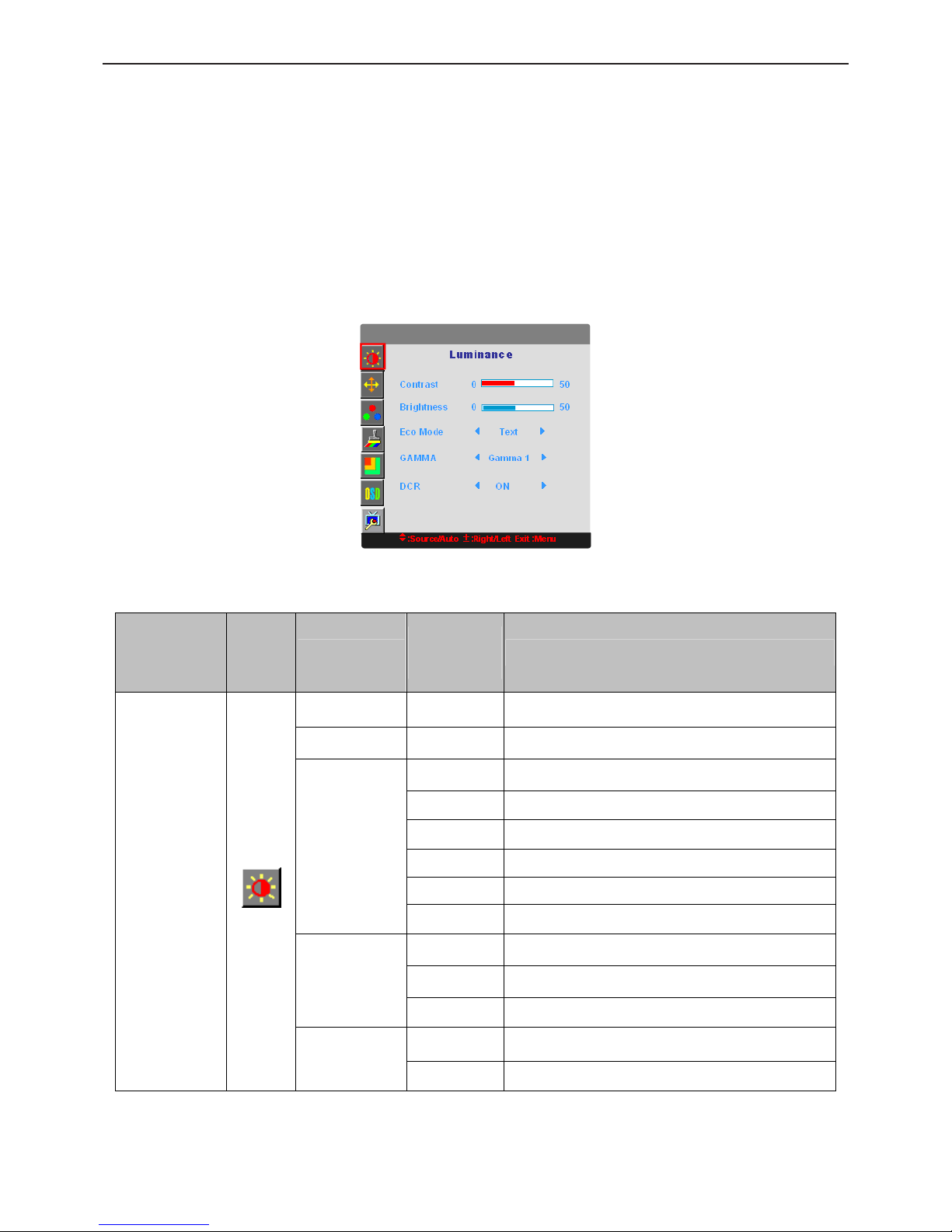
The OSD Message
• OSD functions
Main Menu
Item
Main
Menu
Icon
Sub Menu Item
Sub Menu
Icon
Description
Brightness Backlight Adjustment
Contrast Contrast from Digital-register.
Standard Standard Mode
Text Text Mode
Internet Internet Mode
Game Game Mode
Movie Movie Mode
Eco
Sports Sports Mode
Gamma1 Adjust to Gamma1
Gamma2 Adjust to Gamma 2
Gamma
Gamma3 Adjust to Gamma 3
Off Disable dynamic contrast ratio
Luminance
DCR
On Enable dynamic contrast ratio
15.6" LCD Color Monitor HCL HCMDLWBT21&HCMDLWBN21
8
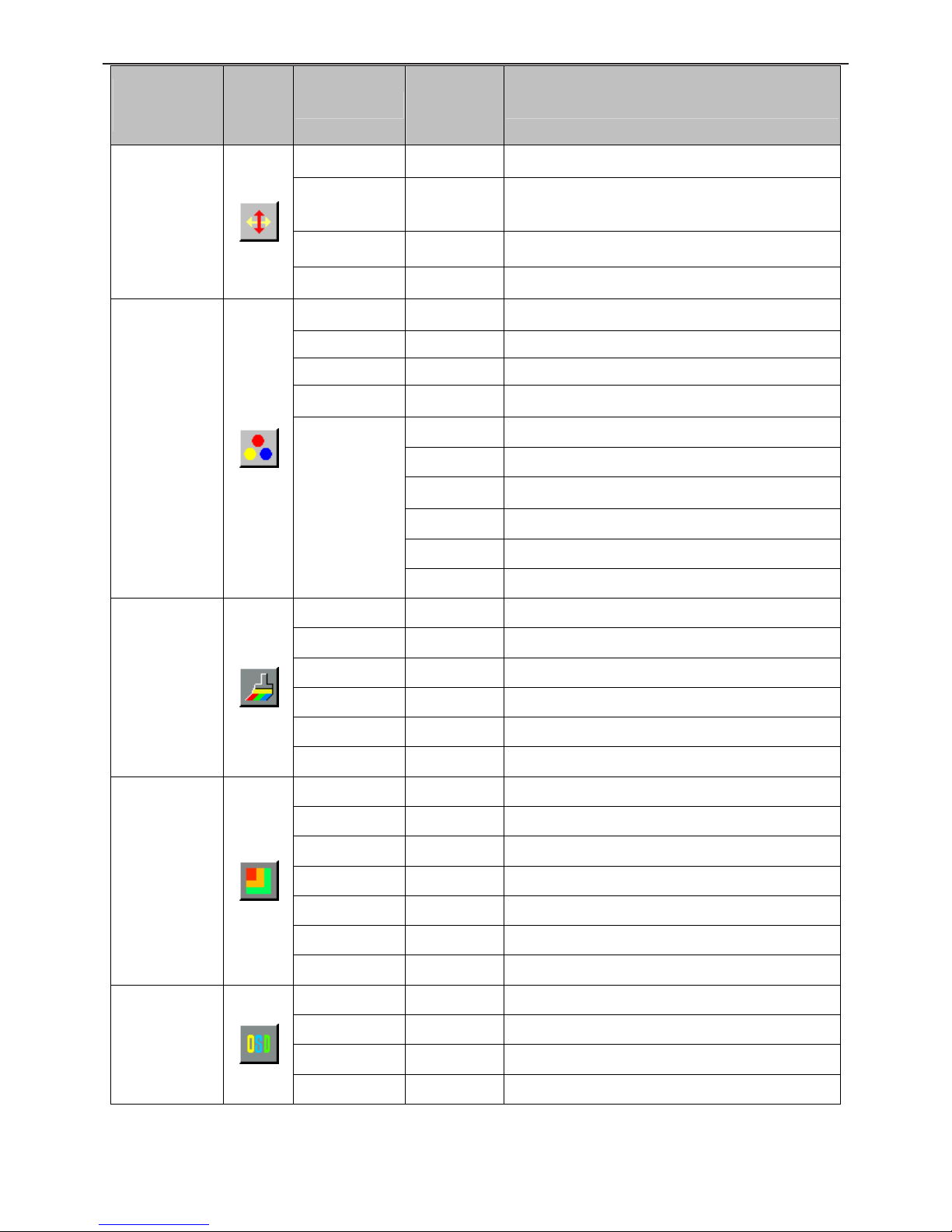
Main Menu
Item
Main
Menu
Icon
Sub Menu Item
Sub Menu
Icon
Description
Clock Adjust picture Clock to reduce Vertical-Line noise.
Focus
Adjust Picture Phase to reduce Horizontal-Line
noise
H. Position Adjust the vertical position of the picture.
Image Setup
V. Position Adjust the horizontal position of the picture.
Warm Recall Warm Color Temperature from EEPROM.
Normal Recall Normal Color Temperature from EEPROM.
Cool Recall Cool Color Temperature from EEPROM.
sRGB Recall SRGB Color Temperature from EEPROM.
User-B Blue Gain from Digital-register
User-G Green Gain from Digital-register.
User-R Red Gain from Digital-register
User-Y Yellow Gain from Digital-register
User-C Cyan Gain from Digital-register
Color Temp.
User
User-M Magenta Gain from Digital-register
Full Enhance on or off Disable or Enable Full Enhance Mode
Nature Skin on or off Disable or Enable Nature Skin Mode
Green Field on or off Disable or Enable Green Field Mode
Sky-blue on or off Disable or Enable Sky-blue Mode
AutoDetect on or off Disable or Enable AutoDetect Mode
Color Boost
Demo
on or off Disable or Enable Demo
Frame Size Adjust Frame Size
Brightness Adjust Frame Brightness
Contrast Adjust Frame Contrast
Hue Adjust Frame Hue
Saturation Adjust Frame Saturation
Position Adjust Frame Position
Picture Boost
Bright Frame on or off Disable or Enable Bright Frame
H. Position Adjust the vertical position of OSD
V. Position Adjust the horizontal position of OSD
Timeout Adjust the OSD Timeout
OSD Setup
Language Select the OSD language
15.6" LCD Color Monitor HCL HCMDLWBT21&HCMDLWBN21
9
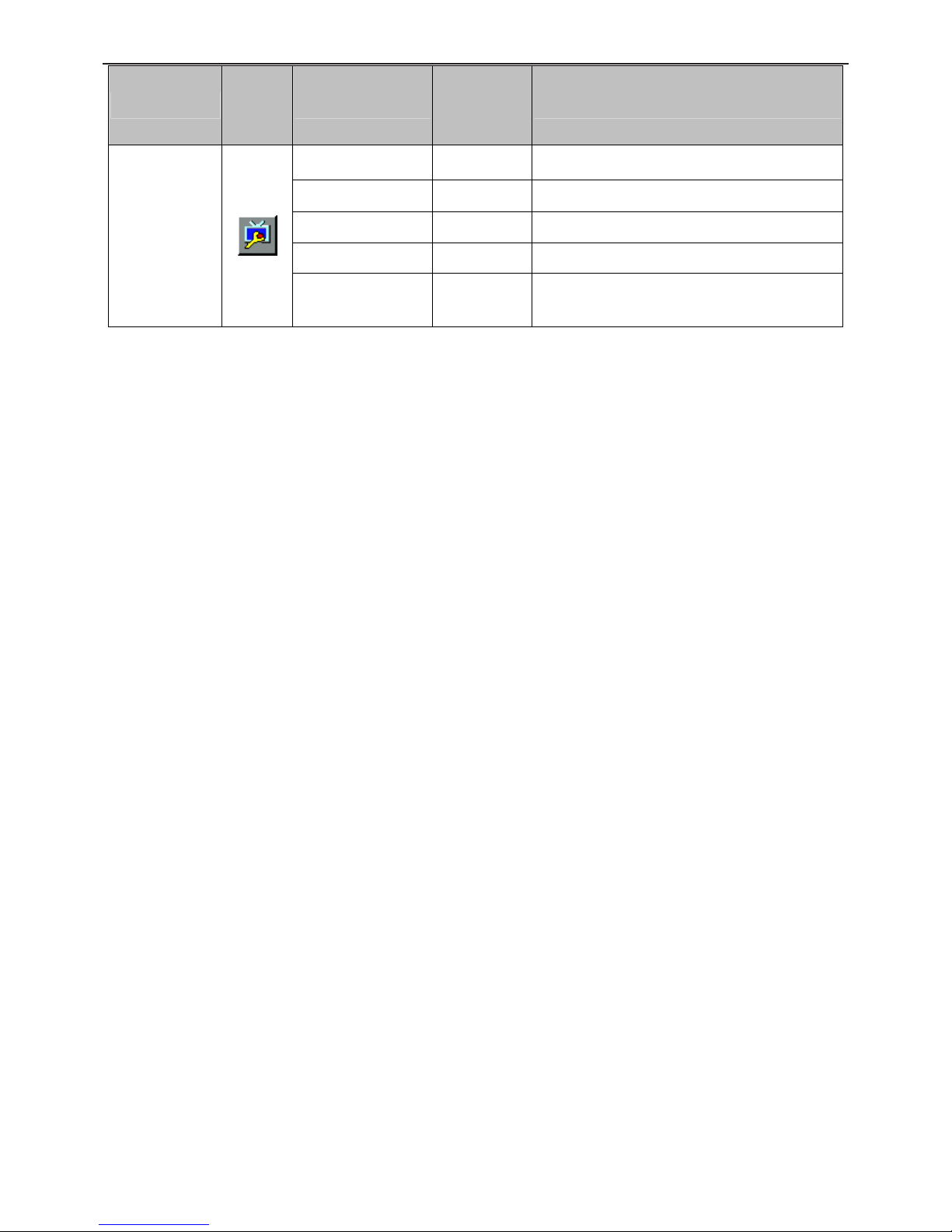
Main Menu Item
Main
Menu
Icon
Sub Menu Item
Sub Menu
Icon
Description
Input Select Analog/ Digital Select the analog/ digital.
Auto Config Auto adjust the picture to default
DDC/CI Turn ON/OFF DDC/CI Support
Reset yes or no Reset the menu to default
Extra
Information
Show the information of the main image and
sub-image source
15.6" LCD Color Monitor HCL HCMDLWBT21&HCMDLWBN21
10
4. Input/Output Specification
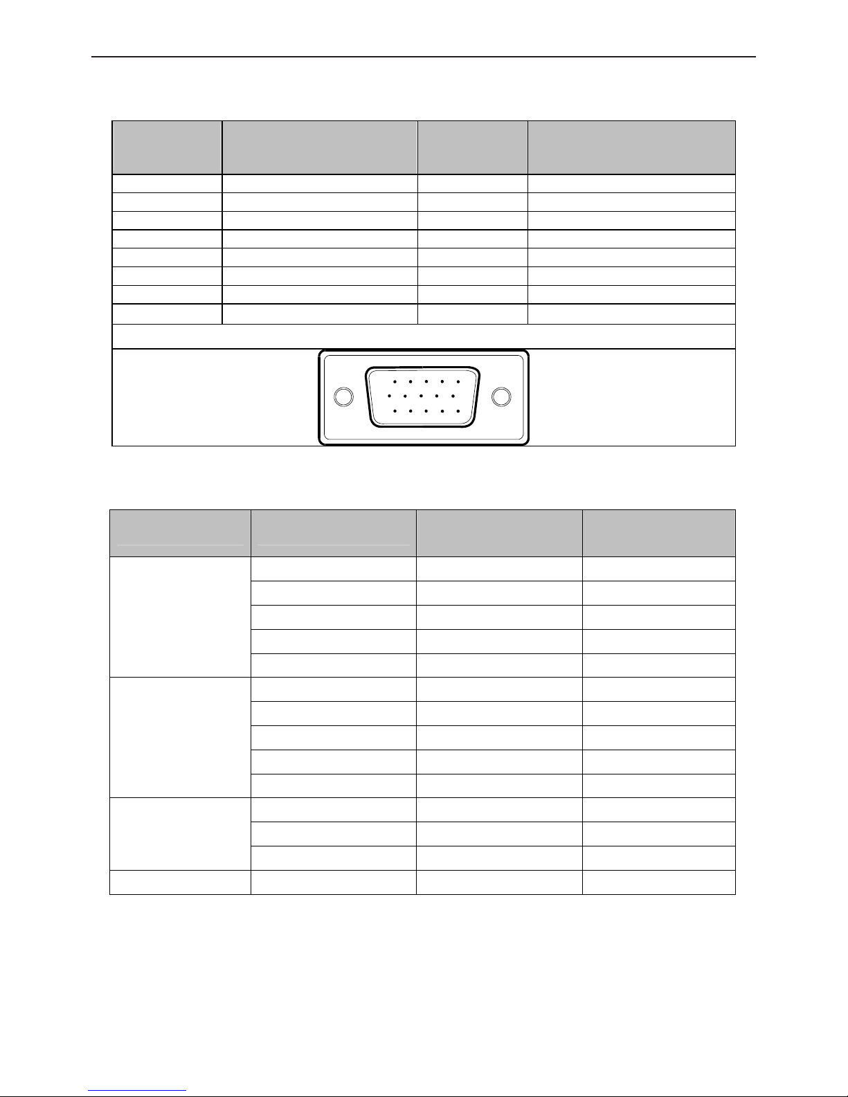
4.1 Input Signal Connector
Pin No. Description Pi N No. Description
1. Red 9. +5V
2. Green 10. VGA-CON
3. Blue 11. RDX
4. TDX 12. DDC-Serial Data
5. Ground 13. H-Sync
6. R-Ground 14. V-Sync
7. G-Ground 15. DDC-Serial Clock
8. B-Ground
15 - Pin Color Display Signal Cable
15
6
10
11 15
4.2 Factory Preset Display Modes
Stand Resolution
Horizontal
Frequency(KHz)
Vertical
Frequency(Hz)
720 x 400 31.47 70.0
640 × 480 31.47 60.0
640 × 480 35.00 66.6
640 × 480 37.50 75.0
VGA
640 × 480 37.861 72.8
800 × 600 35.156 56.3
800 × 600 37.879 60.0
800 × 600 48.077 72.2
800 × 600 46.875 75.0
SVGA
832 x 624 49.725 75.0
1024 × 768 48.363 60.0
1024 × 768 56.476 70.0
XGA
1024 × 768 60.02 75.0
WXGA 1360 × 768 47.712 60.0
15.6" LCD Color Monitor HCL HCMDLWBT21&HCMDLWBN21
11
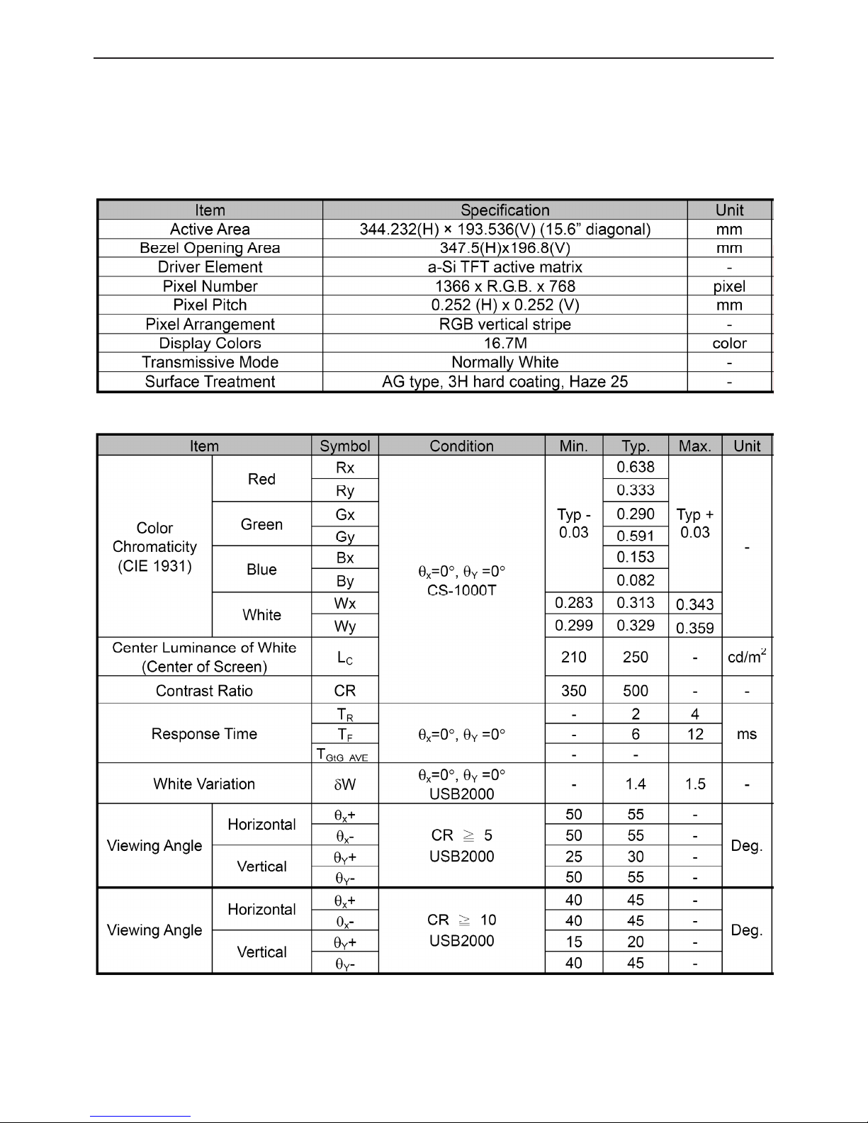
4.3. Panel Specification
4.3.1 General Feature
M156B1-L01 is a 15.6” TFT Liquid Crystal Display module with 2 CCFL Backlight unit and 30pin 1ch-LVDS interface.
This module supports 1366 x 768 WXGA mode and can display up to 16.7M colors.
The inverter module for Backlight is not built in.
4.3.2 Optical Characteristics
15.6" LCD Color Monitor HCL HCMDLWBT21&HCMDLWBN21
12
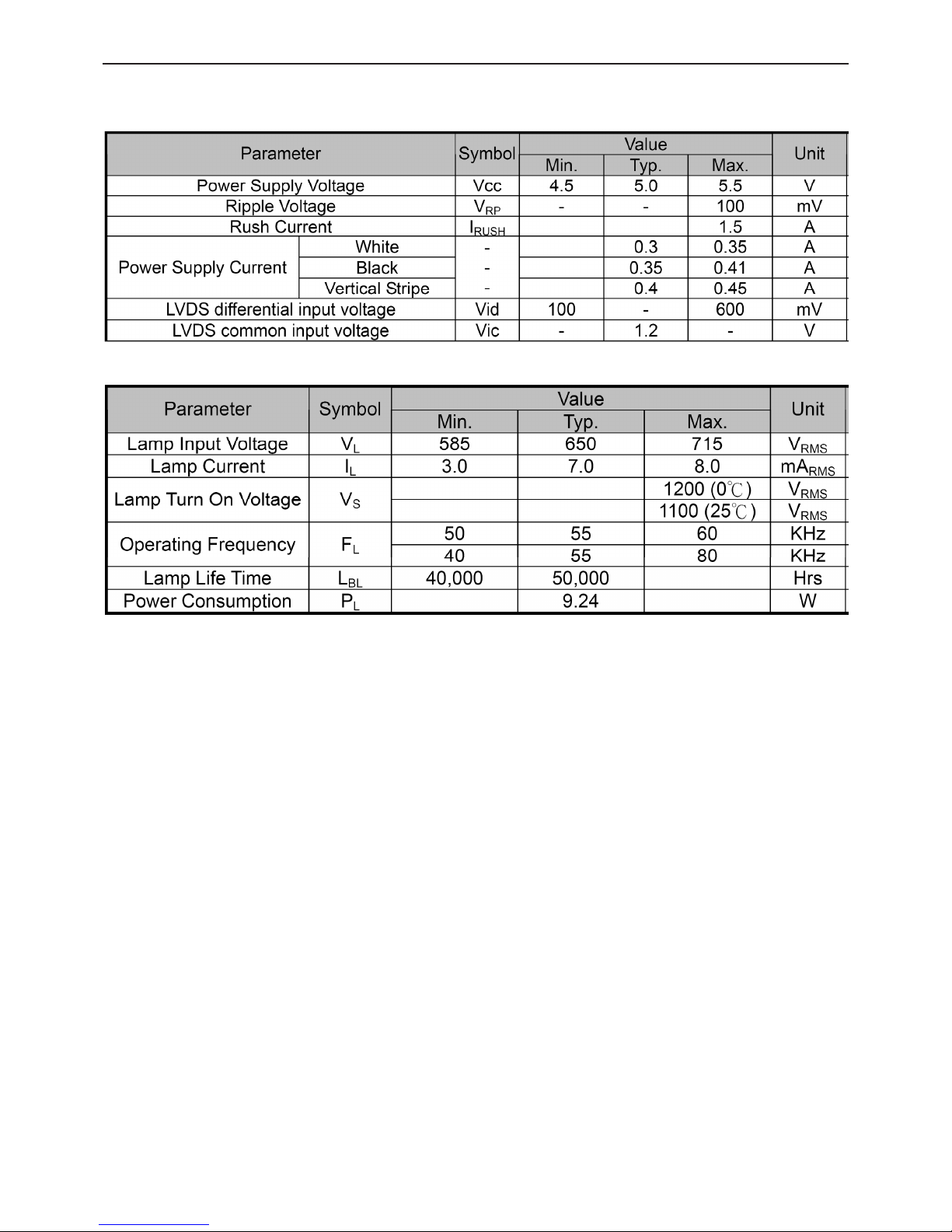
4.3.3 Electrical Characteristics
TFT LCD Module
Backlight Unit
15.6" LCD Color Monitor HCL HCMDLWBT21&HCMDLWBN21
13
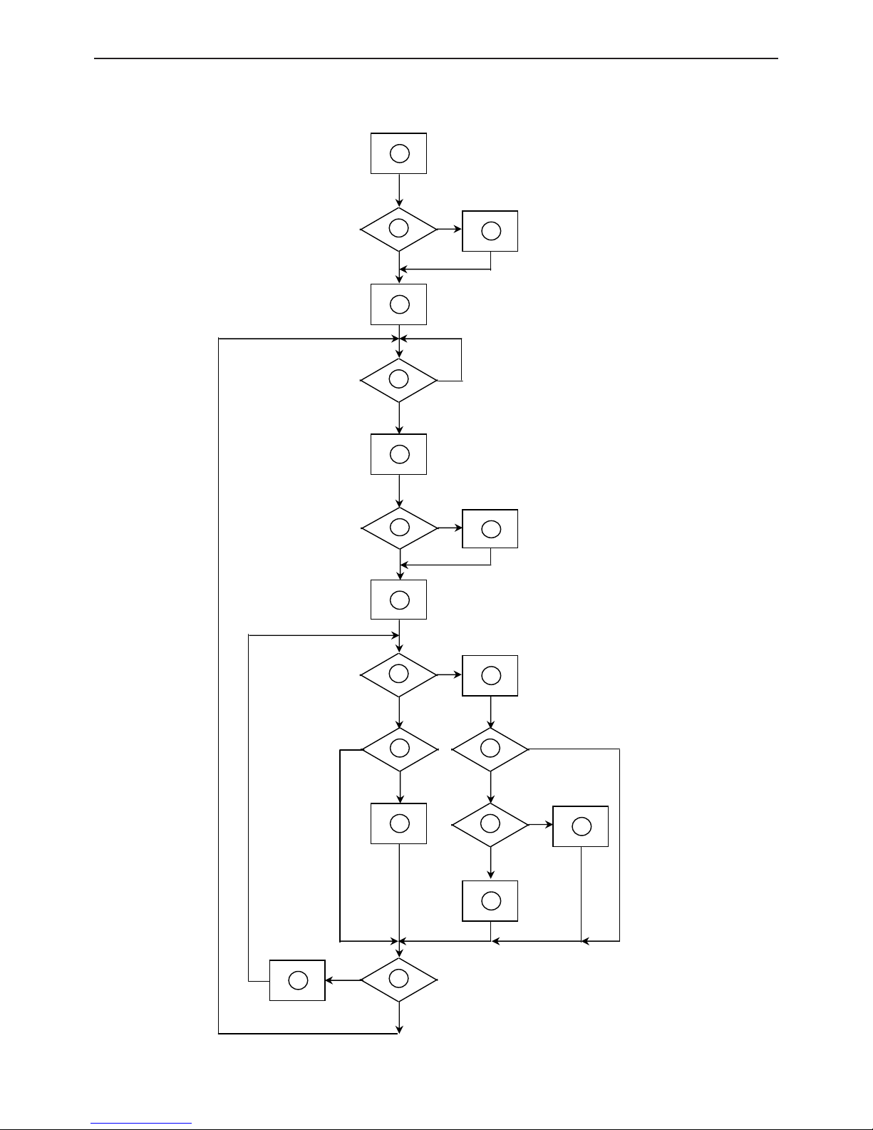
5. Block Diagram
5.1 Software Flow Chart
1
2
N
Y
5
Y
N
10
Y
N
12
Y
N
7
Y
N
6
4
3
8
9
14
11
13
Y
N
15
Y
N
16
17
19
Y
N
18
15.6" LCD Color Monitor HCL HCMDLWBT21&HCMDLWBN21
14
Remark:
1) MCU initialize.
2) Is the EEprom blank?
3) Program the EEprom by default values.
4) Get the PWM value of brightness from EEprom.
5) Is the power key pressed?
6) Clear all global flags.
7) Are the AUTO and SELECT keys pressed?
8) Enter factory mode.
9) Save the power key status into EEprom.
Turn on the LED and set it to green color.
Scalar initializes.
10) In standby mode?
11) Update the lifetime of back light.
12) Check the analog port, are they’re any signals coming?
13) Does the scalar send out an interrupt request?
14) Wake up the scalar.
15) Are there any signals coming from analog port?
16) Display "No connection Check Signal Cable" message. And go into standby mode after the message
disappears.
17) Program the scalar to be able to show the coming mode.
18) Process the OSD display.
19) Read the keyboard. Is the power key pressed?
15.6" LCD Color Monitor HCL HCMDLWBT21&HCMDLWBN21
15
5.2 Electrical Block Diagram
Main Board
Panel Interface
(CN601)
Crystal
24MHZ
(X401)
MCU RTD2120L
(U401)
Scalar RTD2025L
(Include ADC, OSD)
(U501)
D-Sub Connector
(CN301)
H sync
V sync
RGB
EEPROM
M24C16
(U403)
Key Button
(CN202)
15.6" LCD Color Monitor HCL HCMDLWBT21&HCMDLWBN21
16
Power Board
AC input
100V~240V
VEMI filter Rectifier
Transformer
Output
Rectifier
5V
12V
Main
Board/Inverter
Circuit
Power Switching
Sense Resistor
PWM Control IC
IC Power Supply
Photo Couple
Sampling
12V DC
Switching MOS
Transformer
Resonance NET
High Voltage Output
IC Power Supply
Converter
PWM Control IC Open Lamp Protection
Current Sampling
15.6" LCD Color Monitor HCL HCMDLWBT21&HCMDLWBN21
17
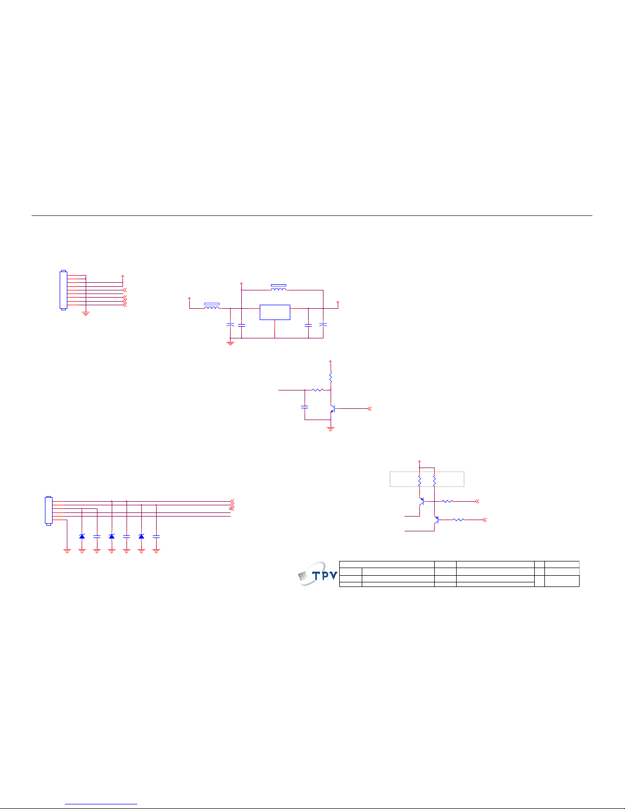
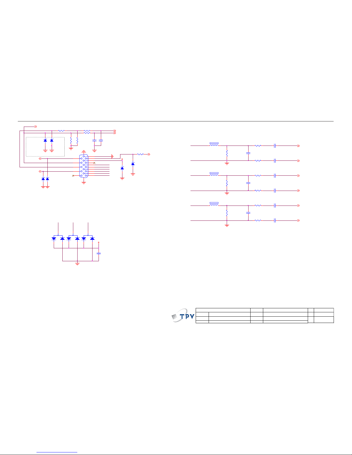
6. Schematic
6.1 Main Board
715G2498 1 AO
1 2
ZD202
NC
LED_R
FB201
120
FB202
NC
1
2
3
4
5
6
CN202
CONN
PANEL_ID# {4}
KEY0 {4}
KEY1 {4}
Near to Connect
LED_G
KEY0
C210
0.1uF/16V
1 2
ZD201
NC
KEY1
MVCC
LED_R
1 2
ZD203
NC
Volume# {4}
* BKLT-EN High O N(3.3V)
Mute {4}
Q204
PMBS3906
OEM MODEL
Size
Rev
Date
Sheet
of
TPV MODEL
PCB NAME
称爹
T P V ( Top Victory Electronics Co . , Ltd. )
Key Component
絬 隔 瓜 絪 腹
1.0
B
26Thursday, J une 26, 2008
715G2498-1-AO
<
称爹
>
2.POWER
+
C203
100uF/25V
VCC3
BKLT-EN
VCC3
+
C202
100uF/25V
C204
0.1uF/16V
DIM# {4}
POWER_KEY # {4}
Q205
PMBS3906
CMVCC
CMVCC
LED_R# {4}
LED_G# {4}
C205
0.1uF/16V
1
2
3
4
5
6
7
8
9
CN201
CONN
C206
0.1uF/16V
VSS
1
VOUT
2
VIN
3
U201
AP1117E33LA
C209
0.1uF/16V
C201
0.1uF/16V
LED_G
BKLT-VBRI
C_PANEL_IN DEX
BKLT-EN
CMVCC
CMVCC
Volume#
Mute
VCC3
R210 10K 1/16W
R213 10K 1/16W
R207
120R 1/16W
R208
120R 1/16W
R201
200 1/16W
INV_ON# {4}
Q202
PMBS3904
R202
4K7 1/16W
15.6" LCD Color Monitor HCL HCMDLWBT21&HCMDLWBN21
18
VGA_G-
C315
0.1uF/16V
C305
5pF/50V
C304
0.047uF
C301
0.047uF
C309
0.047uF
C307
0.047uF
C306
0.047uF
C311
0.047uF
VGA_R-
DDC1_SDA{4}
DDC1_SCL{4}
VGA_CON
DSUB_V
1 2
ZD302
UDZS5.6B
1 2
ZD303
UDZS5.6B
DSUB_V {4}
1
6
2
7
3
8
4
9
5
11
12
13
14
15
10
17 16
CN301
DB15
R311 100R 1/ 16W
CMVCC
RTD_B- {5}
RTD_B+ {5}
RTD_R+ {5}
RTD_R- {5}
RTD_G- {5}
RTD_G+ {5}
R307
75R 1/16W
3
1
2
D302
BAV99
RTD_V {5}
RTD_H {5}
R306 100R 1/ 16W
R313 100R 1/ 16W
R309 100R 1/ 16W
R310
75R 1/16W
R301 100R 1/ 16W
C303
22pF
1 2
ZD305
UDZS5.6B
R303 100R 1/ 16W
3
1
2
D301
BAV99
R305
2.2K 1/16W
C302
22pF
R304
2.2K 1/16W
1 2
ZD304
UDZS 5.6B
R314
75R 1/16W
R312 100R 1/ 16W
DSUB_5V
3
1
2
D303
BAV99
R302 0R 05 1/16W
R315 100R 1/ 16W
1 2
FB302
BEAD
R308 100R 1/ 16W
C308
5pF/50V
C310
5pF/50V
OEM MODEL
Size
Rev
Date
Sheet
of
TPV MO DEL
PCB NAME
称爹
T P V ( Top Victory Electronics Co . , Ltd. )
Key Component
絬 隔 瓜 絪 腹
1.0
B
36Thursday, J une 26, 2008
715G2498-1-AO
<
称爹
>
3.INP UT
1 2
FB301
BEAD
1 2
FB303
BEAD
DDC1_SDA
DSUB_H
DSUB_5V
VGA_B+
RTD_B-
RTD_B+
RTD_R-
RTD_R+
RTD_G+
RTD_G-
DDC1_SCL
1 2
ZD307
UDZS5.6B
1 2
ZD301
UDZS 5.6B
VGA_B-
VGA_G-
VGA_R-
VGA_B+
VGA_G+
VGA_R+
VGA_B+
VGA_R+
VGA_G+
DSUB_CONNECT {4}
VGA_R+
VGA_B-
VGA_G+
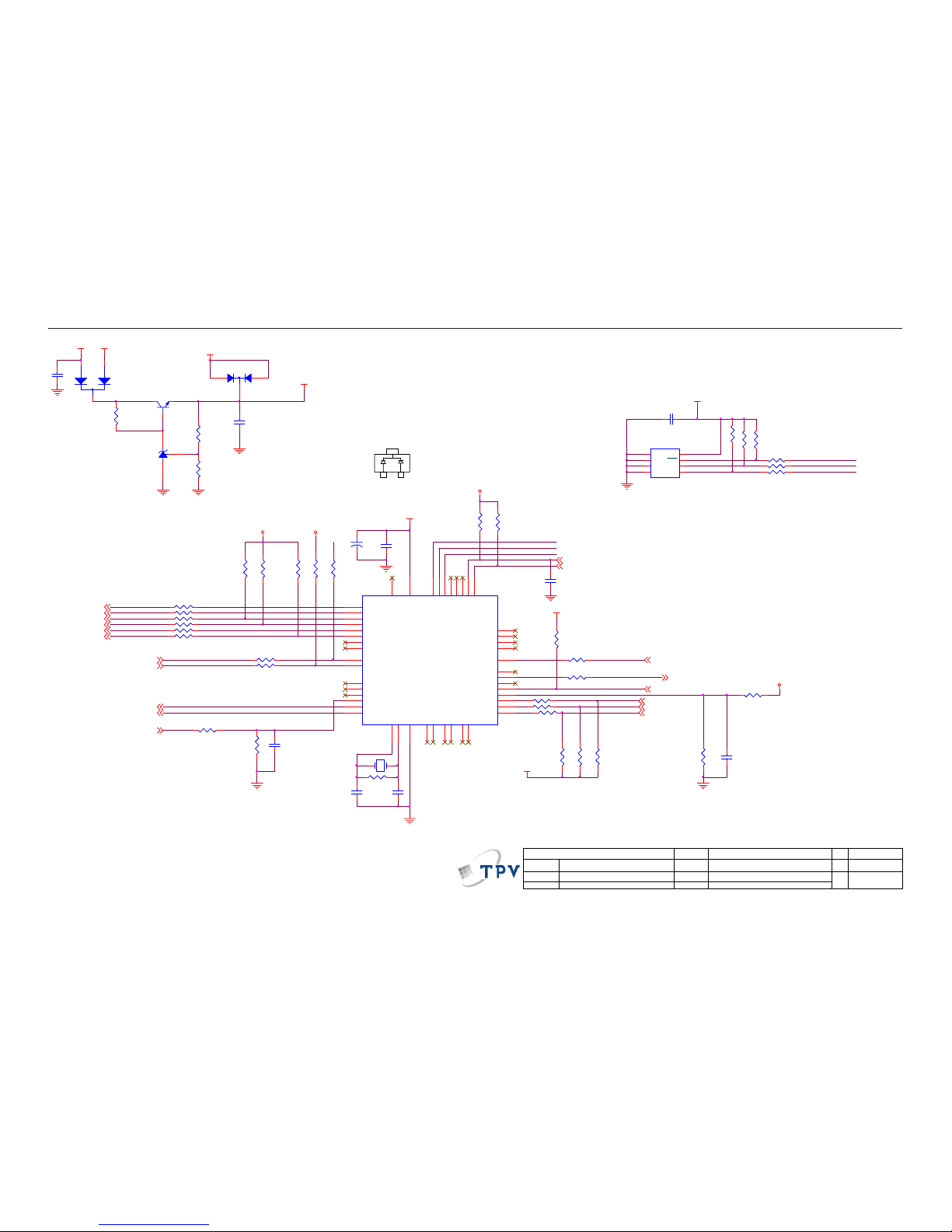
15.6" LCD Color Monitor HCL HCMDLWBT21&HCMDLWBN21
19
R407
4.7K 1/16W
C409
NC(22pF /16V)
C404
0.22uF
R410 100R 1/16W
DDC1_SCL{3}
DDC1_SDA
DDC1_SCL
R411
4K7 1/16W
R412
4K7 1/16W
KEY1 {2}
KEY0 {2}
KEY1
R429 0R 05 1/16W
CRYSTAR_OUT
R438
10K 1/16W
POWER_KEY #
DDC1_SDA{3}
R420 N C 100R 1/16W
R430 10 0R 1/16W
DIM#
INV_ON#
PANEL_ID#
1 2
X40 1
24mhz
MCU _VC C
PANEL_ID#{2}
INV_ON#{2}
Volume#{2}
Volume#
NC
1
NC
2
NC
3
VSS4SDA
5
SCL
6
WC
7
VCC
8
U403
M24C16
Mute{2}
MCU_VCC
C406
0.1uF/1 6V
LED_G#
R422 N C 100R 1/16W
Mute
IICSCL
IICSDA
RTD_SD3/SDI
MCU _VC C
MCU _VC C_S
RTD_SCLK
DSUB_CONNECT
R415
6K8 1/16W
R416
10K 1/16W
C403
0.1uF/16V
DSUB_CONNECT {3}
PPWR_ON#
DIM#{2}
R439
6K8 1/16W
LED_R#
R432 10 0R 1/16W
R414
4.7K 1/16W
R413
4.7K 1/16W
OEM MODEL
Size
Rev
Date
Sheet
of
TPV MODEL
PCB NAME
称爹
T P V ( Top Victory Electronics Co . , Ltd. )
Key Component
絬 隔 瓜 絪 腹
1.0
B
46Thursday , June 26, 2008
715G2498-1-AO
<
称爹
>
4.MCU/RTD2120
PPWR_ON#{6}
RTD_SD3/SDI {5}
RTD_SCLK {5}
DSUB_V {3}
R426 22R 1/16W
R428 22R 1/16W
R436
10K 1/16W
R409 100R 1/16W
R408 100R 1/16W
R406
4.7K 1/16W
+
C405
10uF/50V
R405
4.7K 1/16W
R427 0R 05 1/16W
DSUB_VDSUB_V1
R435 100R 1/16W
R434 100R 1/16W
MCU _VC C
R451
4K7 1/16W
WP
R453
1K 1/16W
R454
1K 1/16W
KEY0
POWER_KEY # {2}
R423 1K 1/ 16W
PANEL_VCC
MCU_VCC
R424 1K 1/ 16W
IICSDA
IICSCL
MVCC
C410
0.1uF/16 V
LED_R#{2}
LED_G#{2}
P5.5/PWM5
1
DSCL2/P5.6
2
DSDA2/P5.7
3
RST
4
ASCL1/P3.0/ RXD
5
NC6NC
7
ASDA1/P3.1/ TXD
8
VSS17XO
15
VCC
41
P1.0/T2
40
P1.139P1.238P1.337P1.436P1.535P1.634P1.7
33
NC
19
VSYNC
28
NC
29
P6.0/ADC0
20
P6.1/ADC1
21
P6.2/ADC2
22
P6.3/ADC3
23
P6.4
24
P6.5
25
P6.6/CLKO1
26
P6.7
27
XI
16
P3.2/INT0
9
P3.3/INT1
10
P3.4/T0
11
P3.5/T1
12
P7.6/CLKO2
13
P7.7
14
NC
18
NC
30
NC
31
NC
32
NC43NC
42
P5.0/PWM0
44
P5.1/PWM1
45
P5.2/PWM2
46
P5.3/PWM3
47
P5.4/PWM4
48
RTD2120L
U401
RTD2120L-LF
C401
10pF
C402
1uF 10V
C412
1uF 10V
Q401
PMBS3904
Closed to MCU
R402
1K 1/16W
DSUB_5V
BAT54C
1
R425
10K 1/16W
C411
10pF
2
R437
3.9K 1/ 16W
MCU_VCC
Closed to X'tal
U402
AZ431AN-AE1
R401
3.9K 1/ 16W
WP
R404
10K 1/16W
R403
3.9K 1/ 16W
3
D402
BAV70
R431
6K8 1/16W
CRYSTAR_OUT {5}
MCU _VC C_ S
CMVCC
1
3
2
D401
BAT54C(NC)
R433 100R 1/16W
CMVCC
VCC3
 Loading...