

HCL HCM9LWAT11 Servise Manual

19"W LCD Color Monitor HCL HCM9LWAT11
1
Service
Service
Service
Horizontal Frequency
30-80 kHz
TABLE OF CONTENTS
Description
Page Description Page
SAFETY NOTICE
ANY PERSON ATTEMPTING TO SERVICE THIS CHASSIS MUST FAMILIARIZE HIMSELF WITH THE CHASSIS
AND BE AWARE OF THE NECESSARY SAFETY PRECAUTIONS TO BE USED WHEN SERVICING
ELECTRONIC EQUIPMENT CONTAINING HIGH VOLTAGES.
Table Of Contents…………………………………………...1
Revision List………………………………………………....2
Important Safety Notice.…….........................……...... 3
1. Monitor Specification..............................…………........4
2. LCD Monitor Description…………………………….......5
3. Operation Instructions....................................…...........6
3.1. General Instructions...........................…....................6
3.2. Control Buttons..………………………….…...............6
3.3 Adjusting the Picture.................................…..............7
4. Input/Output Specification............……………...............9
4.1. Input Signal Connector............…………....................9
4.2. Factory Preset Display Modes......….........................9
4.3. Panel Specification.....………………........................10
5. Block Diagram….........................................................13
5.1 Software Flow Chart………………………….……….13
5.2.Electrical Block Diagram…………………….......15
6. Schematic……………..............................................17
6.1 Main Board....……….............................................17
6.2 Power Board………………………………………....22
6.3 Key Board…………………...….……………………24
6.4 Audio Board…………….……………………………25
7. PCB Layout..………….............................................26
7.1. Main Board………................................................26
7.2. Power Board….....................................................28
7.3. Key Board….........................................................30
7.4. Audio Board…......................................................31
8. Maintainability………...............................................32
8.1.Equipments and Tools Requirement......................32
8.2.Trouble Shooting………........................................32
9. White-Balance, Luminance adjustment………..…...38
10. Monitor Exploded View…………………….…........40
11. BOM List…............................................................41
12. Different Parts List…………………………….…….57
CAUTION: USE A SEPARATE ISOLATION TRANSFOMER FOR THIS UNIT WHEN SERVICING
19"W LCD Color Monitor HCL HCM9LWAT11
2
Revision List
Version Date Revision History TPV Model Name
T974MWDCWJKLAN
A00 Nov.-12-08 Initial release
T974MWDCWJKL8N
A01 Jan.-20-09 Add New BOM T97AMWDCWJKL8N

19"W LCD Color Monitor HCL HCM9LWAT11
3
Important Safety Notice
Proper service and repair is important to the safe, reliable operation of all AOC Company Equipment. The service
procedures recommended by AOC and described in this service manual are effective methods of performing service
operations. Some of these service operations require the use of tools specially designed for the purpose. The
special tools should be used when and as recommended.
It is important to note that this manual contains various CAUTIONS and NOTICES which should be carefully read in
order to minimize the risk of personal injury to service personnel. The possibility exists that improper service
methods may damage the equipment. It is also important to understand that these CAUTIONS and NOTICES ARE
NOT EXHAUSTIVE. AOC could not possibly know, evaluate and advise the service trade of all conceivable ways in
which service might be done or of the possible hazardous consequences of each way. Consequently, AOC has not
undertaken any such broad evaluation. Accordingly, a servicer who uses a service procedure or tool which is not
recommended by AOC must first satisfy himself thoroughly that neither his safety nor the safe operation of the
equipment will be jeopardized by the service method selected.
Hereafter throughout this manual, AOC Company will be referred to as AOC.
WARNING
Use of substitute replacement parts, which do not have the same, specified safety characteristics may create shock,
fire, or other hazards.
Under no circumstances should the original design be modified or altered without written permission from AOC.
AOC assumes no liability, express or implied, arising out of any unauthorized modification of design.
Servicer assumes all liability.
FOR PRODUCTS CONTAINING LASER:
DANGER-Invisible laser radiation when open AVOID DIRECT EXPOSURE TO BEAM.
CAUTION-Use of controls or adjustments or performance of procedures other than those specified herein may
result in hazardous radiation exposure.
CAUTION -The use of optical instruments with this product will increase eye hazard.
TO ENSURE THE CONTINUED RELIABILITY OF THIS PRODUCT, USE ONLY ORIGINAL MANUFACTURER'S
REPLACEMENT PARTS, WHICH ARE LISTED WITH THEIR PART NUMBERS IN THE PARTS LIST SECTION OF
THIS SERVICE MANUAL.
Take care during handling the LCD module with backlight unit
-Must mount the module using mounting holes arranged in four corners.
-Do not press on the panel, edge of the frame strongly or electric shock as this will result in damage to the screen.
-Do not scratch or press on the panel with any sharp objects, such as pencil or pen as this may result in damage to
the panel.
-Protect the module from the ESD as it may damage the electronic circuit (C-MOS).
-Make certain that treatment person’s body is grounded through wristband.
-Do not leave the module in high temperature and in areas of high humidity for a long time.
-Avoid contact with water as it may a short circuit within the module.
-If the surface of panel becomes dirty, please wipe it off with a soft material. (Cleaning with a dirty or rough cloth may
damage the panel.)
19"W LCD Color Monitor HCL HCM9LWAT11
4
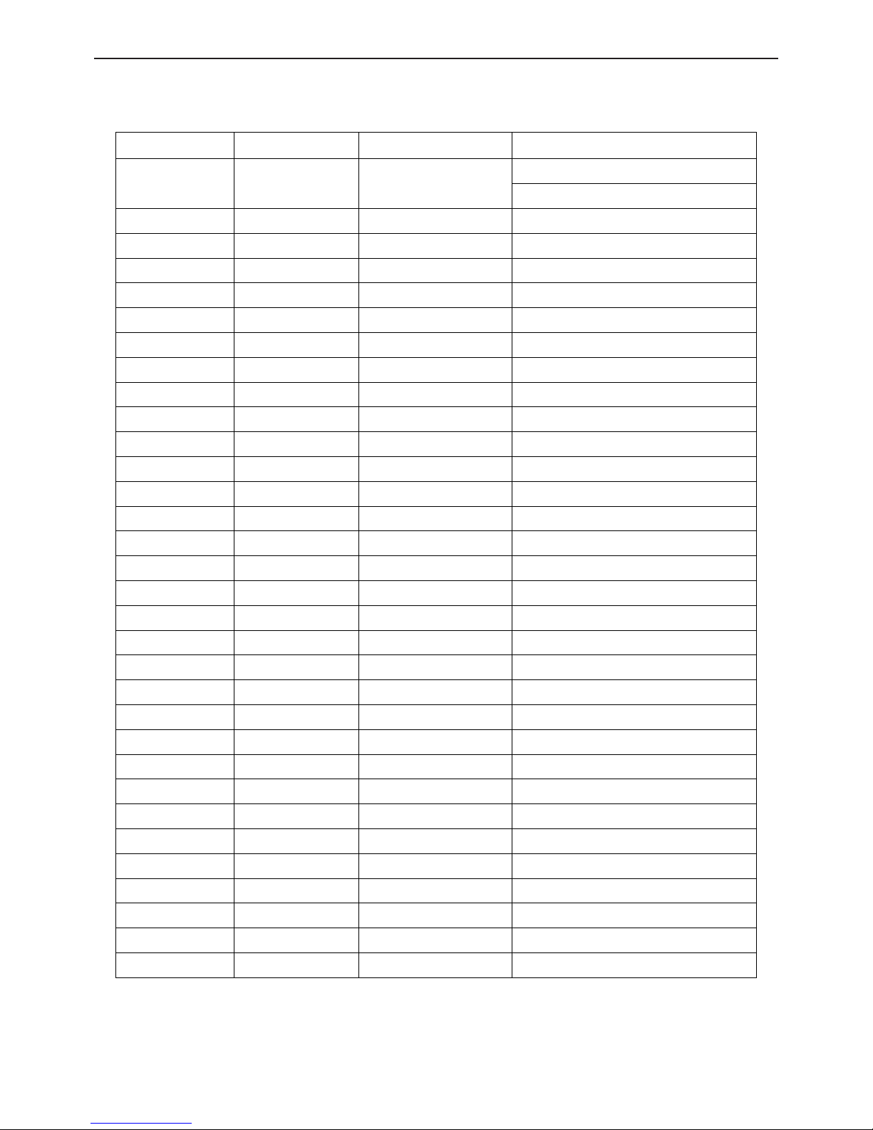
1. Monitor Specification
Driving system TFT Color LCD
Size 48cm(19.0")
Pixel pitch 0.2835mm( H ) × 0.2835mm( V )
LCD Panel
Video R,G,B Analog Interface
Separate Sync. H/V TTL
H-Frequency 30kHz – 80kHz
Input
V-Frequency 55-75Hz
Display Colors 16.2M Colors
Dot Clock 135MHz
Max. Resolution 1440 × 900 @60Hz
Plug & Play VESA DDC2B
TM
ON Mode ≤37W
EPA ENERGY STAR®
OFF Mode ≤1W
Input Connector 15-pin D-Sub
Input Video Signal Analog:0.7Vp-p(standard), 75 OHM, Positive
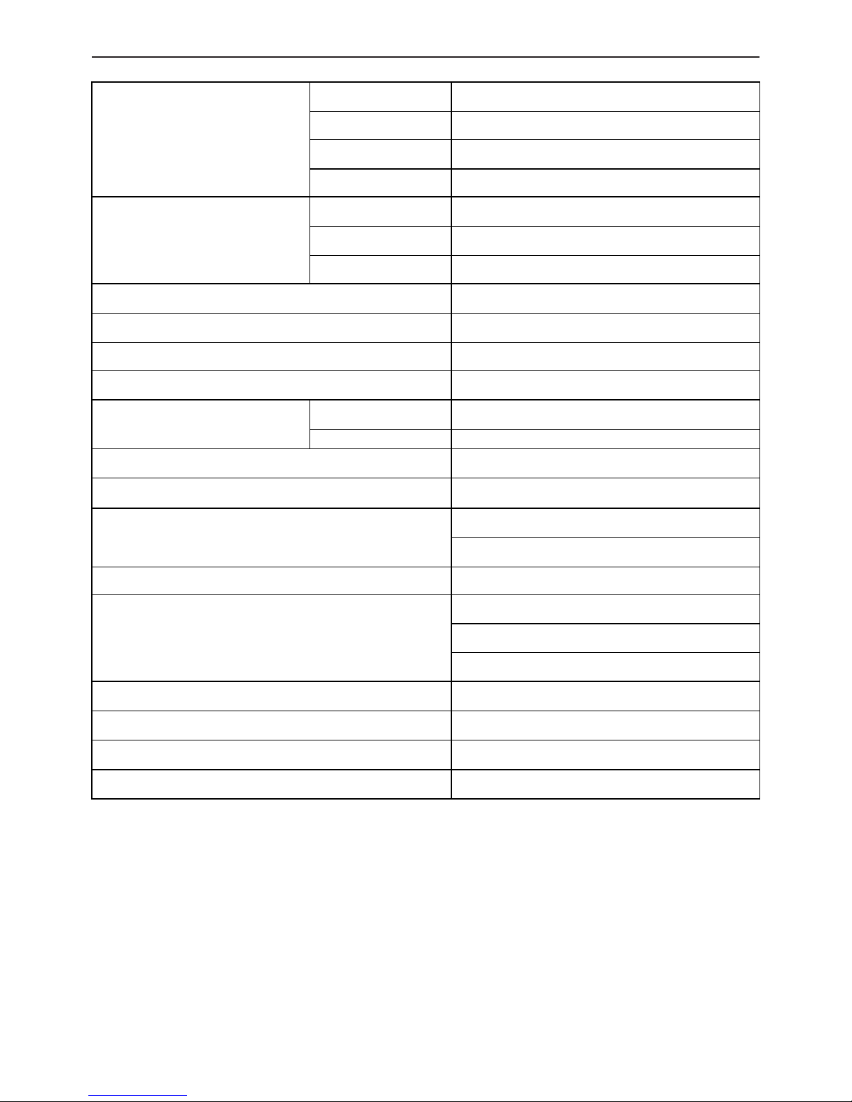
Horizontal : 376.32mm
Maximum Screen Size
Vertical : 301.056mm
Power Source 100~240VAC,50~60Hz
Operating Temp: 5° to 50°C
Storage Temp.: -20° to 60°C
Environmental Considerations
Operating Humidity: 10% to 85%
Dimension 425(W)×418(H)×207(D)mm
Weight 4.8kg Unit (net)
Power Consumption( Maximum ) 37 Watts
Audio Output Rated Power 3.0W rms(Per channel)

19"W LCD Color Monitor HCL HCM9LWAT11
5
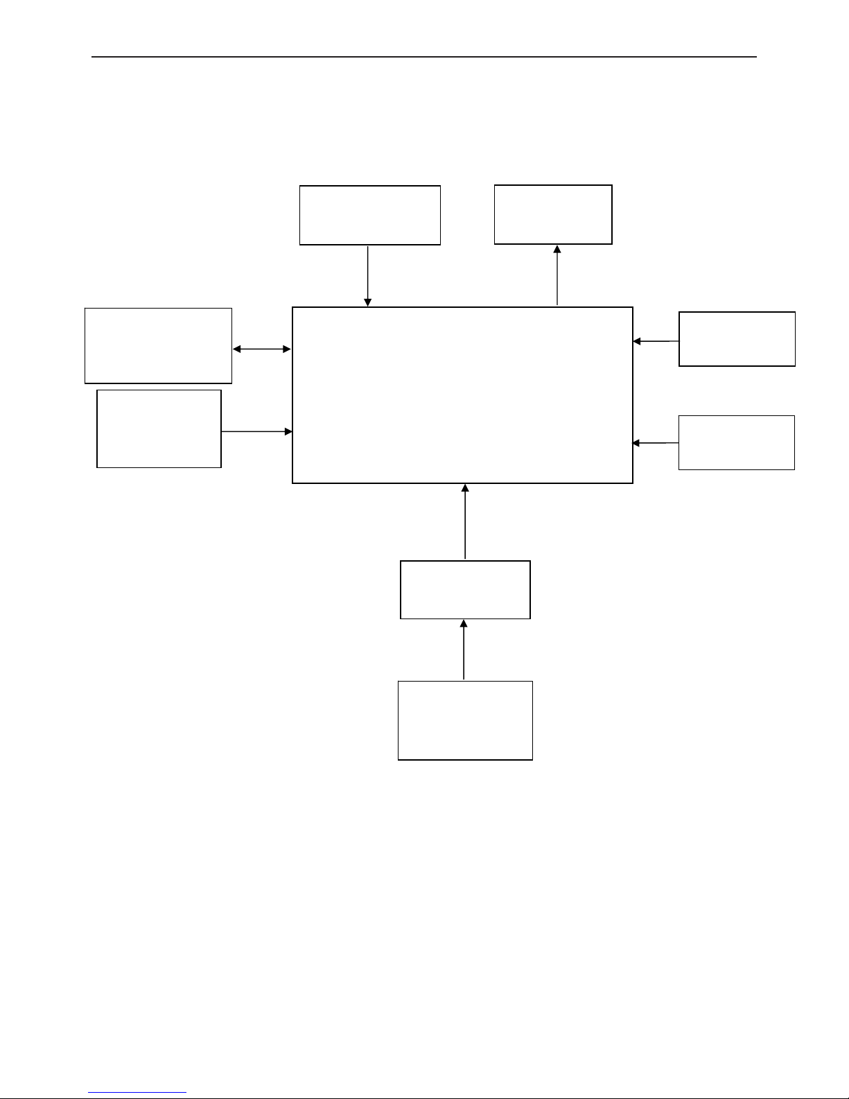
2. LCD Monitor Description
The LCD Monitor will contain main board, power board, key board and an audio board which house the flat panel
control logic, brightness control logic and DDC.
The power board will provide AC to DC Inverter voltage to drive the backlight of panel and the main board chips
each voltage.
Video signal, DDC
Power Board
Flat Panel and
CCFL backlight
Main Board
RS232 Connector
For white balance
adjustment in
factory mode
HOST Computer
CCFT Drive.
AC-IN
100V~240V
Monitor Block Diagram
Key board
Audio board
19"W LCD Color Monitor HCL HCM9LWAT11
6
3. Operation Instructions
3.1 General Instructions
Press the power button to turn the monitor on or off. The other control buttons are located on the front panel of the
monitor. By changing these settings, the picture can be adjusted to your personal preferences.
• The power cord should be connected.
• Connect the video cable from the monitor to the video card.
• Press the power button to turn on the monitor position. The power indicator will light up.
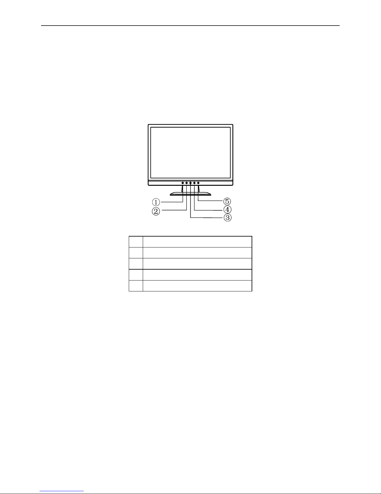
3.2 Control Buttons
External Control Button
1. Auto Adjust Key/Exit
2. < / Volume
3. Power Key/ LED
4. > / Volume
5. MENU/ENTER
Front Panel Control
• Power Button / Power Indicator:
Press this button to turn the monitor ON or OFF.
Blue — Power On mode.
Orange — Off mode.
• MENU / ENTER :
Activate OSD menu when OSD is OFF or activate/de-activate adjustment function when OSD is ON or Exit OSD
menu when in Volume Adjust OSD status.
• > /Volume:
Activates the volume control when the OSD is OFF or navigate through adjustment icons when OSD is ON or
adjust a function when function is activated.
• < /Volume:
Activates the volume control when the OSD is OFF or navigate through adjustment icons when OSD is ON or
adjust a function when function is activated.
• Auto Adjust button / Exit:
1. When OSD menu is in active status, this button will act as EXIT-KEY (EXIT OSD menu).
19"W LCD Color Monitor HCL HCM9LWAT11
7
2. When OSD menu is in off status, press this button for 2 seconds to activate the Auto Adjustment function.
The Auto Adjustment function is used to set the HPos, VPos, Clock and Focus.
OSD Lock Function: To lock the OSD, press and hold the MENU button while the monitor is off and then press
power button to turn the monitor on. To un-lock the OSD - press and hold the MENU button while the monitor is
off and then press power button to turn the monitor on.
3.3 Adjusting the Picture
• OSD Settings
1. Press the MENU-button to activate the OSD window.
2. Press < or > to navigate through the functions. Once the desired function is highlighted, press the MENU-button
to activate it. If the function selected has a sub-menu, press < or > again to navigate through the sub-menu functions.
Once the desired function is highlighted, press MENU-button to activate it.
3. Press < or > to change the settings of the selected function.
4. To exit and save, select the exit function. If you want to adjust any other function, repeat steps 2-3.
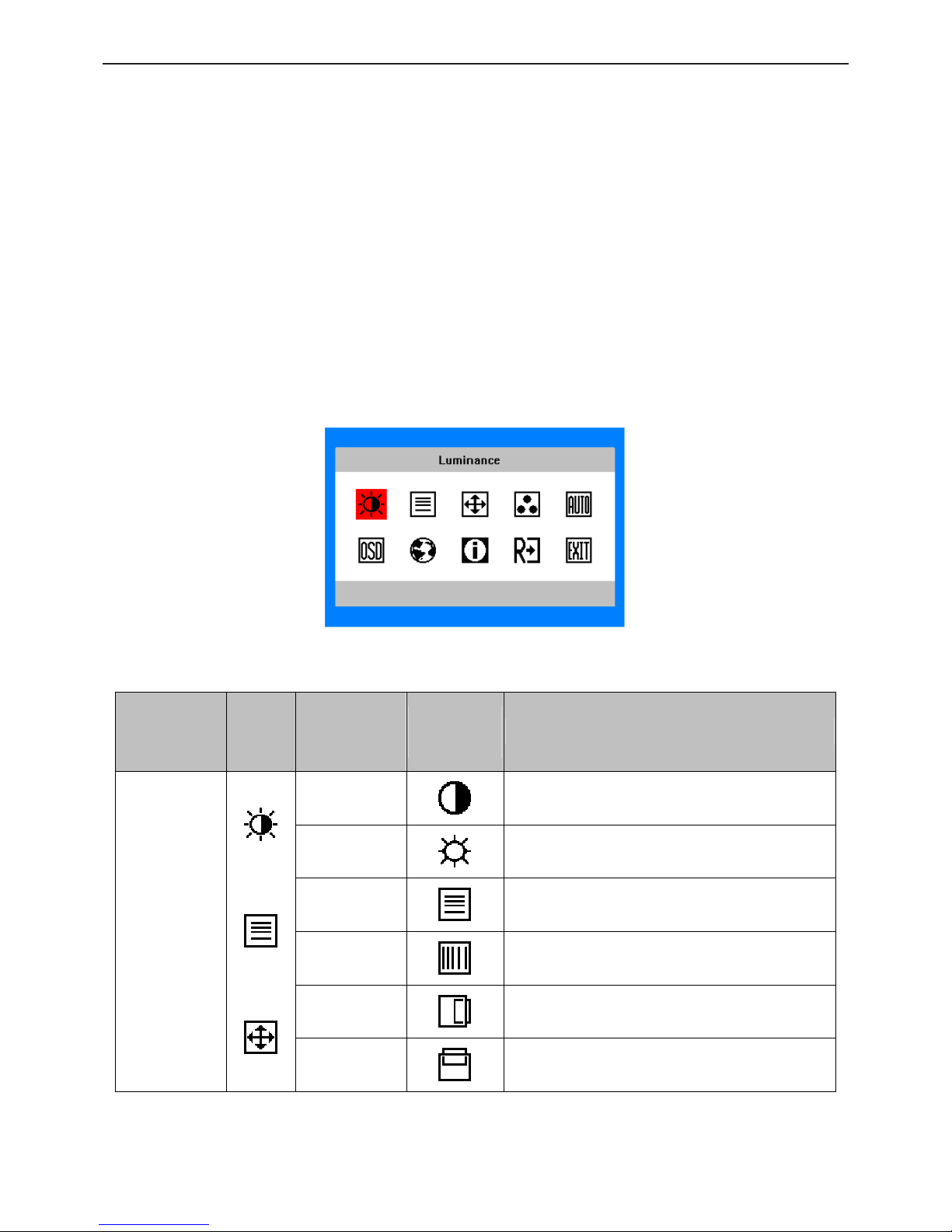
The OSD Message
•
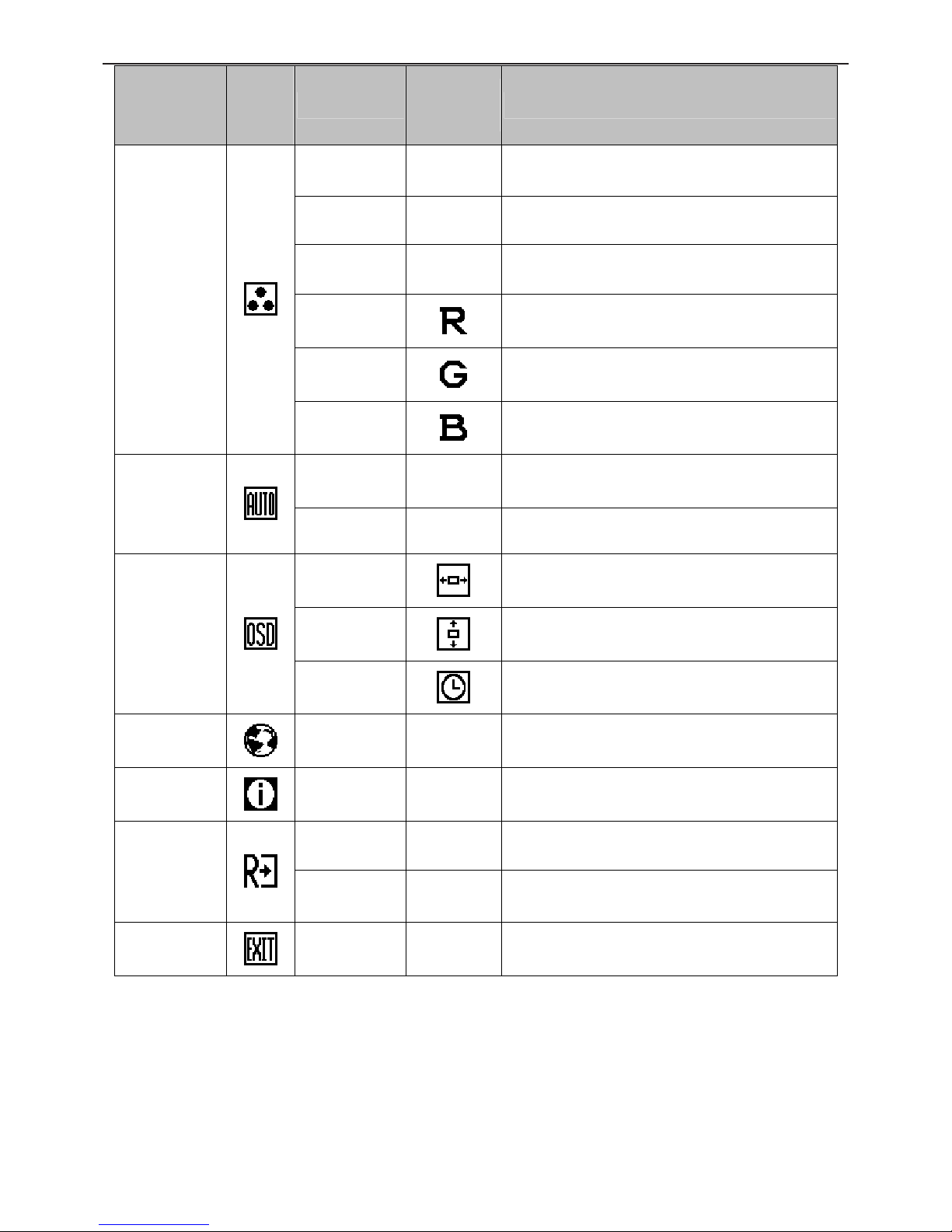
OSD functions
Main Menu
Item
Main
Menu
Icon
Sub Menu Item
Sub Menu
Icon
Description
Contrast
Contrast from Digital-register.
Luminance
Brightness
Backlight Adjustment.
Focus
Adjust Picture Phase to reduce Horizontal-Line
noise.
Image Setup
Clock
Adjust picture Clock to reduce Vertical-Line noise.
H. Position
Adjust the horizontal position of the picture.
Image Position
V. Position
Adjust the vertical position of the picture.
19"W LCD Color Monitor HCL HCM9LWAT11
8
Main Menu
Item
Main
Menu
Icon
Sub Menu Item
Sub Menu
Icon
Description
Warm N/A Recall Warm Color Temperature from EEPROM.
Cool N/A Recall Cool Color Temperature from EEPROM.
sRGB N/A Recall sRGB Temperature from EEPROM.
User / Red
Red Gain from Digital-register.
User / Green
Green Gain from Digital-register.
Color Temp.
User / Blue
Blue Gain from Digital-register.
Yes N / A
Auto Adjust the H/V Position, Focus and Clock of
picture.
Auto Config
No N/A
Do not execute Auto Config, return to main menu.
H. Position
Adjust the horizontal position of the OSD.
V. Position
Adjust the vertical position of the OSD.
OSD Setup
OSD Timeout
Adjust the OSD timeout.
Language
Language N/A Set OSD language.
Information
Information N/A
Show the resolution, H/V frequency and input port
of current input timing.
Yes N/A Clear each old status of Auto-configuration.
Reset
No N/A Do not execute reset, return to main menu.
Exit
N/A N/A Exit OSD.
19"W LCD Color Monitor HCL HCM9LWAT11
9
4. Input/Output Specification
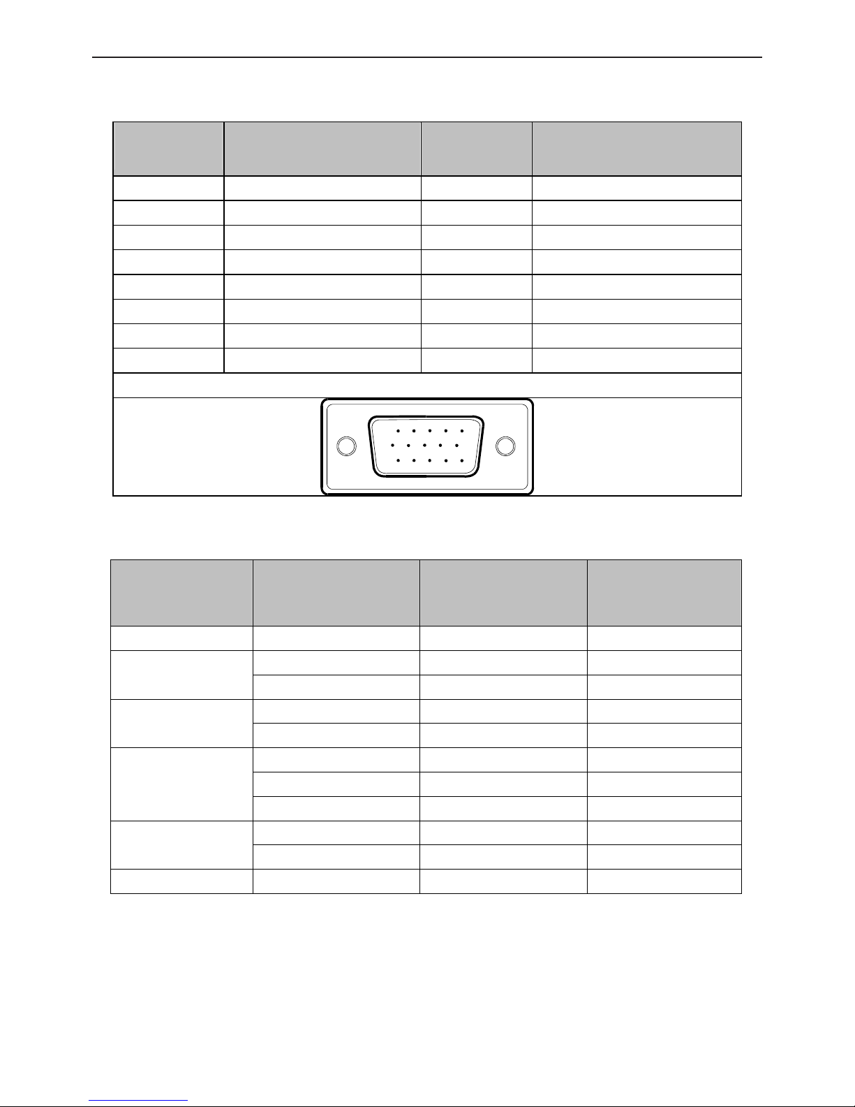
4.1 Input Signal Connector
Pin No.
Description
Pi N No.
Description
1. Red 9. +5V
2. Green 10. Detect Cable
3. Blue 11. Ground
4. Ground 12. DDC-Serial Data
5. Ground 13. H-Sync
6. R- Ground 14. V-Sync
7. G- Ground 15. DDC-Serial Clock
8. B- Ground
15 - Pin Color Display Signal Cable
15
6
10
11 15
4.2 Factory Preset Display Modes
Stand Resolution
Horizontal
Frequency(KHz)
Vertical
Frequency(Hz)
Dos-mode 720×400 31.47kHz 70.0Hz
640×480 31.47kHz 60.0Hz
VGA
640×480 37.50kHz 75.0Hz
800×600 37.879kHz 60.0Hz
SVGA
800×600 46.875kHz 75.0Hz
1024×768 48.363kHz 60.0Hz
1024×768 56.476kHz 70.0Hz
XGA
1024×768 60.021kHz 75.0Hz
1280 × 1024 64.000kHz 60.0Hz
SXGA
1280 × 1024 80.000kHz 75.0Hz
WXGA+ 1440×900 55.935 kHz 60.0 Hz
19"W LCD Color Monitor HCL HCM9LWAT11
10
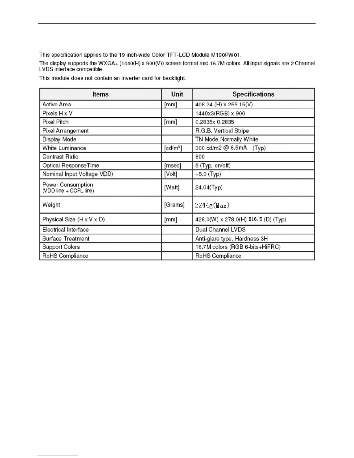
4.3. Panel Specification
4.3.1 General Feature
19"W LCD Color Monitor HCL HCM9LWAT11
11
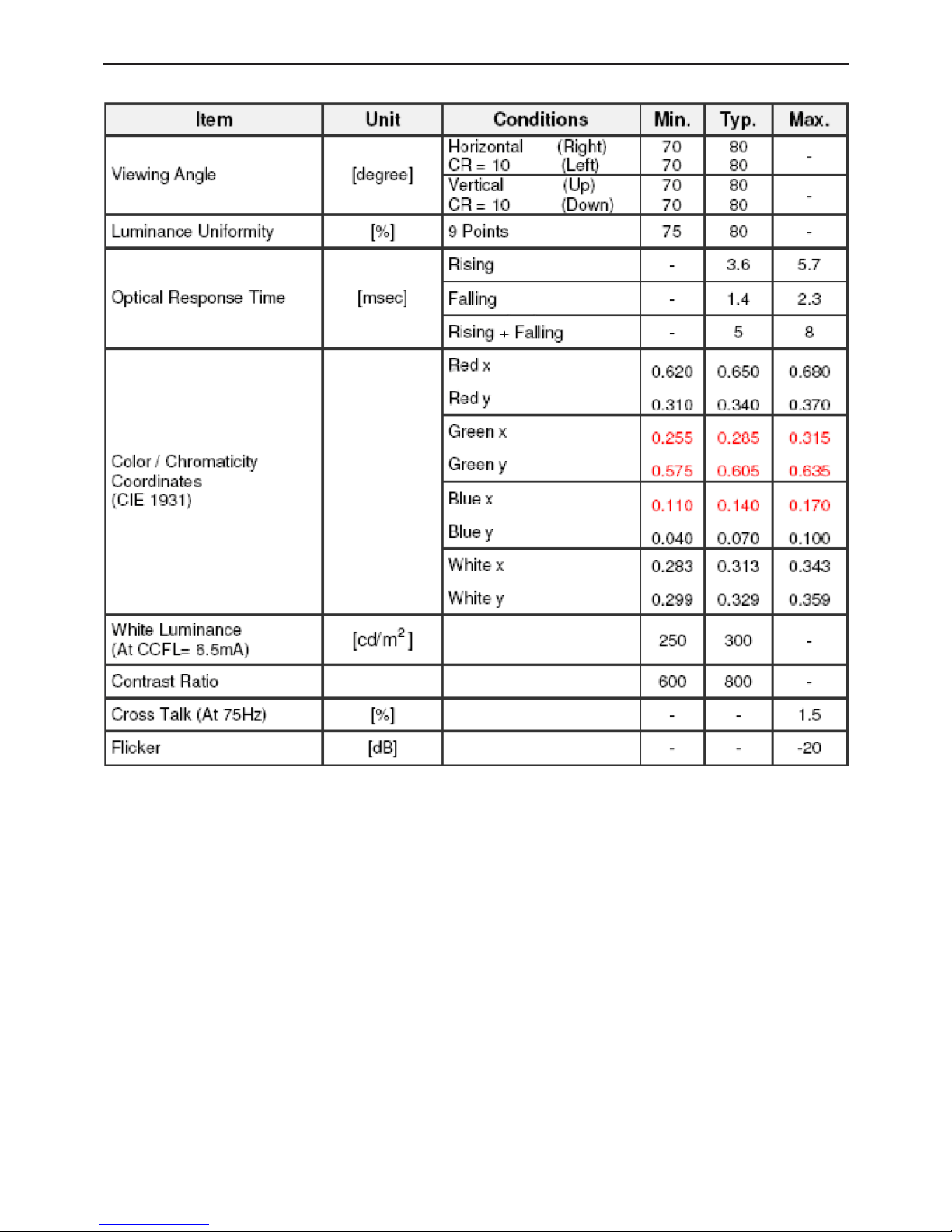
4.3.2 Optical Characteristics
19"W LCD Color Monitor HCL HCM9LWAT11
12
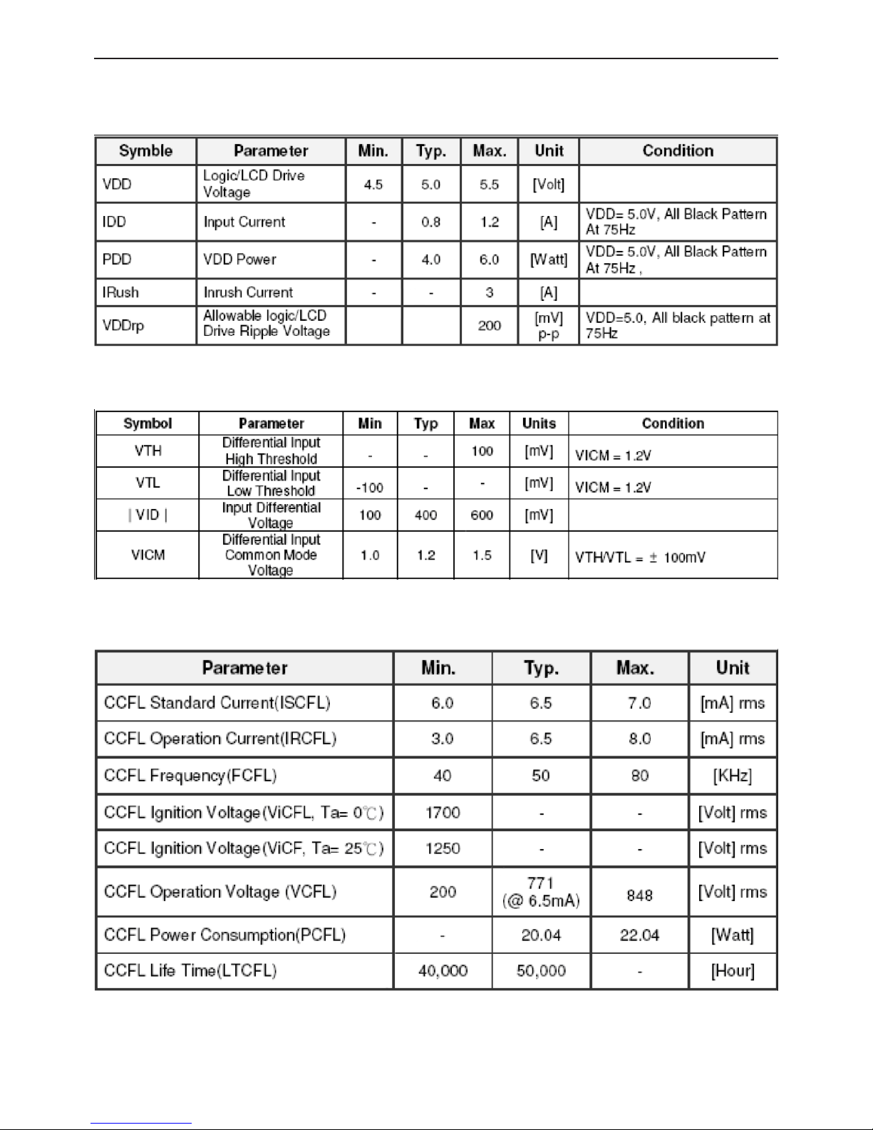
4.3.3 Electrical Characteristics
TFT LCD Module
·Power Specification
·Signal Electrical Characteristics
Backlight Unit
19"W LCD Color Monitor HCL HCM9LWAT11
13
5. Block Diagram
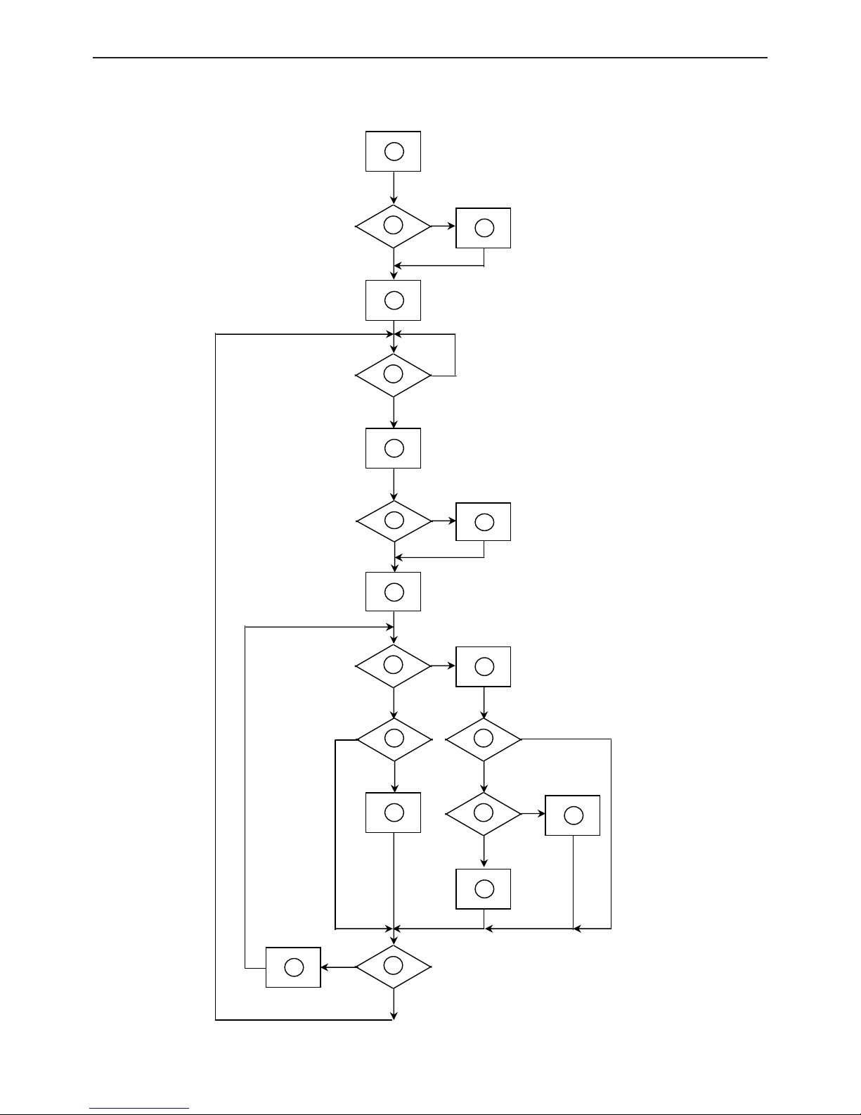
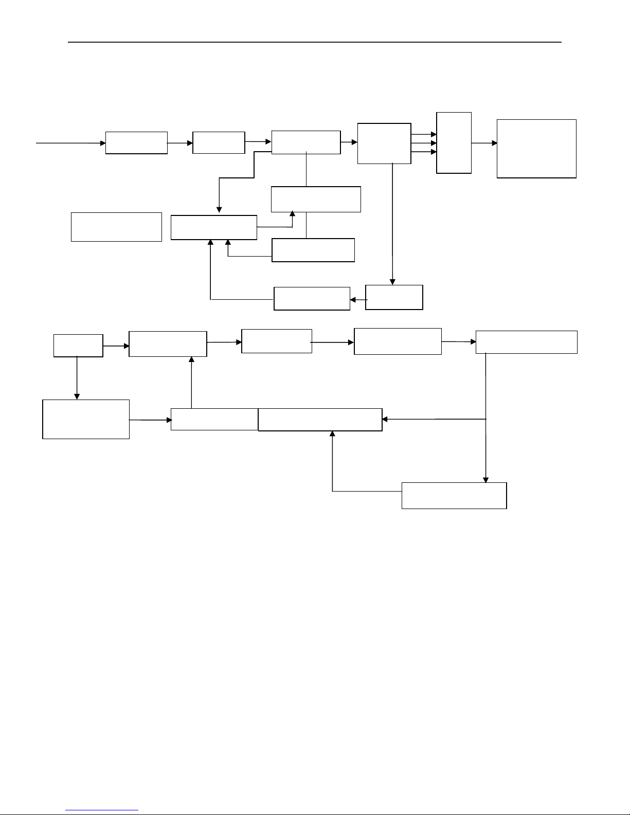
5.1 Software Flow Chart
1
2
N
Y
5
Y
N
10
Y
N
12
Y
N
7
Y
N
6
4
3
8
9
14
11
13
Y
N
15
Y
N
16
17
19
Y
N
18
19"W LCD Color Monitor HCL HCM9LWAT11
14
Remark:
1) MCU initialize.
2) Is the EEprom blank?
3) Program the EEprom by default values.
4) Get the PWM value of brightness from EEprom.
5) Is the power key pressed?
6) Clear all global flags.
7) Are the AUTO and SELECT keys pressed?
8) Enter factory mode.
9) Save the power key status into EEprom.
Turn on the LED and set it to green color.
Scalar initializes.
10) In standby mode?
11) Update the lifetime of back light.
12) Check the analog port, are they’re any signals coming?
13) Does the scalar send out an interrupt request?
14) Wake up the scalar.
15) Are there any signals coming from analog port?
16) Display "No connection Check Signal Cable" message. And go into standby mode after the message
disappears.
17) Program the scalar to be able to show the coming mode.
18) Process the OSD display.
19) Read the keyboard. Is the power key pressed?
19"W LCD Color Monitor HCL HCM9LWAT11
15
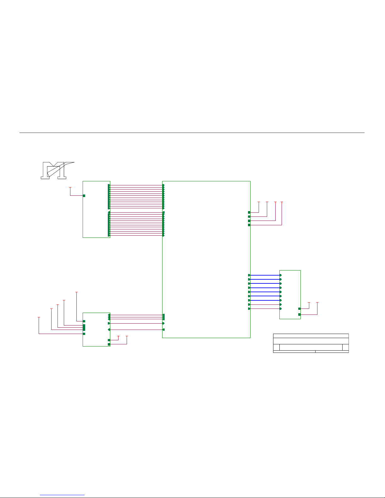
5.2 Electrical Block Diagram
Main Board
Crystal 14.318MHZ
(X401)
FLASH ROM
SST25LF020A
(
U402
)
Scalar TSUM16AWK-LF-1
(Include ADC, OSD, MCU)
(U401)
D-Sub Connector
(CN405)
Panel Interface
(CN101)
Key Button
(CN403)
EEPROM
M24C02-WMN6TP
(U404)
EEPROM
M24C16
(U403)
Audio Board
(CN404)
19"W LCD Color Monitor HCL HCM9LWAT11
16
Power Board
AC input
100V~240V
VEMI filter Rectifier
Transformer
Output
Rectifier
5V
12V
Main
Board/Inverter
Circuit
Power Switching
Sense Resistor
PWM Control IC
IC Power Supply
Photo Couple
Sampling
12V DC
Switching MOS
Transformer
Resonance NET
High Voltage Output
IC Power Supply
Converter
PWM Control IC Open Lamp Protection
Current Sampling
19"W LCD Color Monitor HCL HCM9LWAT11
17
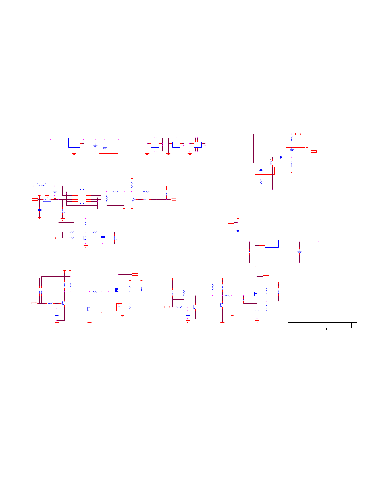
6. Schematic
6.1 Main Board
715G1558 1 BJ
Titl e
Size Document Number Rev
Date: Sheet
of
A
TOP
B
15Tuesday, December 19, 2006
+5V
+5V
TSUM16AWK-LF-1 SCHEMATIC
VCC3.3
PA[0..7]
PA[14..19]
PB[0..5]
PB[6..11]
GPO[0..4]
TPV(Top Victory)Electronics Co.,Ltd
VLCD_12V
VLCD_12V
PB[12..23]
G1558-1-BJ-X-5-061218
B3
3.INPUT
RIN
GIN
BIN
VSYNC
GNDR
GNDG
GNDB
DET_VGA
HSYNC
SOG
B+
CLK-
DET_DVI
CLK+
R+
G+
R-
B-
G-
DDCA_SDA
DDCA_SCL
DDCD_SDA
DDCD_SCL
+5V
DDC_WP
LVDS OUTPUTXGA/SXGA
B5
5.PANEL INTERFACE
VLCD
PA[0..7]
PA[8..13]
ESP
PA[14..19]
PB[0..5]
PB[6..11]
GPO[0..4]
OSP
VLCD_12V
PB[12..23]
B4
4.SCALER
RIN
GIN
SOG
BIN
GNDR
GNDG
GNDB
HSYNC
VSYNC
Adj_BACKLIGHT
VCC1.8
Vcc3.3
VCTRL
PA[0..7]
PA[8..13]
R+
R-
G-
G+
B+
BCLK+
CLKDDCD_SDA
DDCD_SCL
DET_DVI
DDCA_SDA
DDCA_SCL
DET_VGA
on_BACKLIGHT
on_Panel
+5V
PA[14..19]
PB[0..5]
PB[6..11]
GPO[0..4]
ESP
OSP
on_PANEL_12V
PB[12..23]
+12V
DDC_WP
B2
2.POW ER
on_Panel
on_BACKLIGHT
Adj_BACKLIGHT
+3V3
VCC1.8
VLCD
+5V
VCTRL
VCC3.3
on_PANEL_12V
VLCD_12V
+12V
VCC1.8
VCC3.3
+3V3
VLCD
VCC1.8
VLCD
TSUM16AWK
+12V
PA[8..13]
+12V
+5V
19"W LCD Color Monitor HCL HCM9LWAT11
18
C709
0.1uF 50V
+
C703
NC
VCC3.3
VCC3.3 4
R702
51Ω 1/10W
+
C710
100uF/25V
C711
0.1uF 50V
VCC1.8 4
VCTRL 4
VCC3.3 4
+5V
+5V3,4
R740
NC
R739
15KΩ 1/10W
3 2
1 Q707
NC
1 2
L702
120Ω
C727
0.1uF 50V
R705
4.7KΩ 1/10W
Q701
PMBS3904
R707
4.7KΩ 1/10W
R711
10KΩ 1/10W
2
4
6
8
10
12
1
3
5
7
9
11
CN701
CONN
Q709
NC
+
C717
10uF/50V
R717
10KΩ 1/10W
C715
0.022uF
11223
3
4
4
5
5
66778
8
9
9
H3
TP
C721
0.1uF 50V
GND
32
1 Q708
NC
R735
4.7KΩ 1/10W
Q704
AO3401
C724
NC
GND
R733
NC
R734
10KΩ 1/10W
R727
NC
GND
C701
NC
VI3VO
2
GND
1
VO
4
U701
NC
+5V +3V3
+
C704
NC
SOT-223
D702
SS14
C713
0.1uF 50V
D701
SS14
BL_ADJ
+3V3
R723
51 KOHM +- 5% 1/10W
D704
SS14
GND
R724
NC
GND
C722
NC
R736
NC
R737
NC
GND
C714
0.1uF 50V
TPV(Top Victory)Electronics Co.,Ltd
Q702
PZT2907A
+5V
adj_BACKLIGHT
4
on_PANEL
4
on_PANEL_12V
4
G1558-1-BJ-X-5-061218
For RSDS and Panel VCC=12V
123Q706
PMBS3906
VIN
3
ADJ
1
VOUT
2
U702
AIC1084-33PM
C716
0.022uF
+12V
+5V
+12V
4
+
C723
22uF/50V
1
32
Q705
NC
For LVDS PANEL
R712
4.7KΩ 1/10W
R710 NC
R706
NC
+
C719
NC
R722
NC
+5V3,4
R719
NC
Q703
PMBS3904
TO-263
R701
1KΩ 1/10W
+
C707
47uF/25V
R721
0Ω 1/10W
11223
3
4
4
5
5
66778
8
9
9
H1
TP
R716
NC
C706
0.1uF 50V
11223
3
4
4
5
5
66778
8
9
9
H2
TP
C708
1uF
R708
10KΩ 1/10W
R728
NC
on_BACKLIGHT 4
VLCD_12V 5
VLCD 5
1 2
L701
120Ω
+5V +12 V
+5V
+12V
+3V3
VLCD_12V
+5V
+5V
VLCD
+5V
+3V3
Title
Size Document Number Rev
Date: Sheet
of
A
Power
Custom
35Tuesday, D ecember 19, 2006
R731
NC
+5V
R729
NC
+5V
+
C712
100uF/25V
BL_ON
R720
NC
+12V
VCC3.3
+
C702
22uF/50V
R704
100Ω 1/10W
R730
NC
VCC1.8
R703
2KΩ 1/10W
 Loading...