

HCI RoomMate RM20II, RoomMate RM22II, RoomMate RM26II, RoomMate RM32II, RoomMate RM42II Operation Manual
...
REVISION 7.0
TM


--------------------------------------------------------------------------------------
GEN
II OPERATIONS MANUAL
HealthCare Information, LLC
3
TABLE OF CONTENTS
SAFETY INSTRUCTIONS
5-7
PACKAGE CONTENTS
8
PRODUCT INTRODUCTION
9-13
IR REMOTE
9
LEFT SIDE INPUT PANEL
10
FRONT PANEL USB PORT
10
FRONT PANEL
10
REAR JACK PANEL (SGL PILLOW V1) 11
REAR JACK PANEL (SGL PILLOW
V2) 12
REAR JACK PANEL (DUAL PILLOW) 13
INSTALLATION
14
-16
ANTENNA
14
COMPOSITE A/V
14
COMPONENT A/V
14
PC
15
EXTERNAL SPEAKERS
15
EXTERNAL MONITOR
15
PILLOW SPEAKER(S)
15
THIRD PARTY CONTROLLERS
16
SOFTWARE UPDATES
16
SETUP AND OPERATION
17-32
BASIC SETUP
17-20
IR BATTERIES
17
FUNCTION CODES
17
PILLOW SPEAKER
17
AUTO SCAN
18
DATE AND TIME
18
FM SETUP
18, 19
ALARM
19
ADVANCED SETUP
21-32
PICTURE MENU
21
PICTURE MODE
21
CONTRAST
21
BRIGHTNESS
21
HUE
(TINT)
21
C
OLOR LEVEL
21
COLOR TONE
21
SCREEN SIZE (ZOOM)
21
3D NR
21
SOUND MENU
22- 24
SPEAKER MODE
22
SOUND MODE
22
BASS
22
TREBLE
22
BALANCE
22
MTS
22
CLOSED
CAPTION
22-23
MIN/MAX VOLUME
23-24
TELEVISION
23
SINGLE PILLOW SPEAKER 23
DUAL PILLOW SPEAKER 24
ADVANCE MENU
25, 26
USB CLONING
25
START-UP SETTINGS
25
SOURCE
25
CHANNEL NUMBER
25
VOLUME
25
MENU LANGUAGE
25
MENU TRANSPARENCY 25
MENU DISPLAY TIME
25
PARENTAL CONTROL
25
SIP AND PUFF
25
PILLOW SPEAKER TYPE 26
SETUP PASSWORD
26
SYSTEM MENU
27-28
POWER SETTINGS
27
OPERAT
ING HOURS
27
POWER SAVING
27
POWER ROLL
27
ON WITH AC
27
IR BAND SELECT
27
KEYDEFINE
27
KEYPAD LOCK
28
LED CONTROL
28
CLOCK DST
28
SOURCE ROLL
28
SERIAL CONTROL
28
INFORMATION
28
SOURCE SETUP MENU
29-32
TV SETUP
29-31
CHANNEL#
29
ADD/REMOVE
29
FREQUENCY
29
LABEL
29
FINE TUNE
29
SOURCE
29
CH PREVIEW MODE
2
9, 30
SAVE
30
AUTO SCAN
30
DTV SETUP
30, 31
CHANNEL NO
30
A
DD/REMOVE
30
FREQUENCY
30
TUNER SOUR
CE
30
SIGNAL TYPE
30
SAVE
31
AUTO SCAN
31
BANK SELECT
31
BANK EDIT
31
FM SETUP
31
CHANNEL#
31
FREQUENCY
31
LABEL
31
FM LEVEL
31

--------------------------------------------------------------------------------------
GEN
II OPERATIONS MANUAL
HealthCare Information, LLC
4
SCR
EEN MODE
31
FAVORITE LOCK
31
SAVE
31
SOURCE LABELS
31
SOURCE
ROLL
31
INPUT AUTO DETECT
32
GUIDE CHANNEL
32
PATIENT FUNCTIONS
33
INFORMATION
33
CHANNEL INFO
33
DATE & TIME
33
CLEAR FAV
33
FAVORITES
(FAV)/EDUCATION(EDU)
34
CLOSED CAPTIONS
34
IR BANDS
34
PILLOW SPEAKER OPERATION
35
DVD/IPTV PILLOW SPEAKER CONTROL
36
CLONING
37
INTERNET PROTOCOL TELEVISION (IPTV)
38-49
INTRODUCTION
38
IPTV SETUP
39-42
GENERAL IP SETUP
39
IP MODE
39
IP ADDRESS
39
SUBNET MASK
39
GATEWAY ADDRESS
39
MAC ADDRESS
39
CURRENT IP
39
HARD DISK UTILITY
39
HARD DISK UTILITY
39
JPEG DECODING
39
PICTURE TIMER
39
FIRMWARE UPGRADE
39
VERSION
39
UPNP FUNCTION
39
THIN CLIENT SETTINGS
40
SERVER ADDRESS
40
PROGRAM SELECT
40
COLOR SELECT
40
AUTO LOGIN
40
USER NAME
40
PASSWORD
40
HOME PAGE SETTINGS
40-42
PC APPS
40
IMAGES
40
EDUCATION
41
MOVIES
41
AUDIO
41
AUTO PLAY GREEN
41
AUTO PLAY BLUE
41
AUTO PLAY PURPLE
41
ENABLE/DISABLE BUTTONS 42
AUTOMATIC BUTTON
S
42
USB
42
PRESCRIBED MEDIA
42
LOCAL MEDIA
42
MEDIALINK
42
TV
42
USING
IPTV
43, 44
SETTING IP ADDRESS
43
IPTV OPERATION
44
CONTROLLING PLAYBACK 44
HARD DRIVE FILE MANAGEMENT 45
-49
COPYING FROM
USB DRIVE 45
CONNECTING PC
45
WINDOWS XP
45-47
WINDOWS VISTA
47
-48
COPY FILES TO HARD DRIVE
49
DELETING
FILES
49
MENU TREE
50
PARENTAL CONTROL
51, 52
RATING SYSTEM
51, 52
SETUP A
ND OPERATION
52
KEY DEFINE
53
DIGITAL TV SETUP
54
BANKS
55
-56
EDITING
55
COPY
55
RESET
56
CLEAR
56
HDTV
56
UNIVERSAL REMOTE OPERATION
56
SOFTWARE UPDATES
56
ACCESSORIES
57
SPECIFICATIONS
58-65
DIME
NSIONS RM20II
58
DIME
NSIONS RM22II
59
DIME
NSIONS RM26II
60
DIME
NSIONS RM32II
61
DIME
NSIONS RM42II
62
DIME
NSIONS RM52II
63
GENERAL
64, 65
WARRANTY
66

WARNING
To reduce the risk of fire or electric shock, do not expose this apparatus to rain or moisture and this apparatus shall not be exposed to dripping or splashi
ng and
no objects filled with liquids, such as vases, shall be placed on the apparatus.
Do not use this LCD TV Monitor near water. For example: avoid placing it near a bathtub, washbowl, kitchen sink, or laundry tub, in a wet basement, or near a
swimmin
g pool, etc.
This apparatus shall be connected to a mains socket outlet with a protective earthing connection.
The mains plug of this apparatus must remain readily operable.
Advertisement:
Pour réduire le risque du feu ou de décharge électrique, n’expos
ez pas cet appareil à la pluie ou à l’humidité. L’appareil ne sera pas exposé à l’égoutture ou
l’éclaboussement et aucun objet remplis de liquides, tels que des vases, ne seront placés sur l’appareil.
NOTE TO CABLE TV INSTALLER
This remind
er is provided to call the cable TV installer’s attention to Article 820-40 of the National Electric Code (U.S.A.). This code provides guidelines for
proper grounding and, in particular, specifies that the cable ground shall be connected to the grounding
system of the building as close to the point of the cable
entry as practical.
REGULATORY INFORM
This equipment generates, uses and can radiate radio frequency energy, and if not installed in accordance with this instruction manual, may cause harmful
inter
ference to radio communications. However, there is no guarantee that interference will not occur in a particular installation. If this equipment does cause
harmful interference to radio or television reception, which can be determined by turning the equi
pment off and on, the user is encouraged to try to correct the
interference by on or more of the follow measures:
1. Increase the separation between the equipment and receiver.
2. Consult the dealer or an experienced radio/TV technician for help.
CAUTION
Do not attempt to modify this product in any way without written authorization from HealthCare Information, LLC. Unauthorized modification will void the
warranty of the product.
COMPLIANCE
The party responsible for this product’s compliance is:
Healt
hCare Information, LLC, 113 Commerce Blvd., Loveland, OH 45140, USA
. Phone 513-271-8100.
HealthCare Information, LLC
5

--------------------------------------------------------------------------------------
GEN
II OPERATIONS MANUAL
HealthCare Information, LLC
6
IMPORTANT SAFETY INSTRUCTIONS
1)
Read these instructions.
2)
Keep these instructions.
3)
Heed all warnings.
4)
Follow all in
structions.
5)
Do not use this apparatus near water.
6)
Clean only with dry cloth.
7)
Do not block any ventilation openings. Install in
accordance with the manufacture
s instructions.
8)
Do not install near any heat source such as radiators, heat regis
ters, stoves, or other apparatus (including amplifiers)
that produce heat.
9)
Do not defeat the safety purpose of the polarized or grounding type plug. A polarized plug has two blades with one
wider than the other. A grounding type plug has two blades
and a third grounding prong. The wide blade or third
prong are provided for your safety. If the provided plug does not fit into you outlet, consult an electrician for
replacement of the obsolete outlet.
10)
Protect the power cord from being walked on or
pinched particularly at plugs, convenience
receptacles, and the point where they exit from the apparatus.
11)
Only use attachments/accessories specified by the manufacturer.
12)
Use only with the cart, stand, tripod, bracket, or table specified by the
manufacturer, or sold
with the apparatus. When a cart is used, use caution when moving the cart/apparatus
combination to avoid injury from tip-over.

--------------------------------------------------------------------------------------
GEN
II OPERATIONS MANUAL
HealthCare Information, LLC
7
13)
Unplug this apparatus during lightning storms or when unused for long periods of time.
14)
Refer all servicing to qualified service personnel. Servicing is required when the
apparatus has been damaged in any way, such as power-supply cord or plug is
damaged, liquid has been spilled or objects have fallen into the apparatus, the
apparatus has
been exposed to rain or moisture, does not operate normally, or has
been dropped.
---------------------------------------------------------------------------------------
IMPORTANT SAFEGUARDS FOR YOU AND YOUR NEW PRODUCT
YOUR NEW PRODUCT HAS BEEN MANUF
ACTURED AND TESTED WITH YOUR SAFETY IN MIND. HOWEVER,
IMPROPER USE CAN RESULT IN POTENTIAL ELECTRICAL SHOCK OR FIRE HAZARDS. TO AVOID DEFEATING
THE SAFEGUARDS THAT HAVE BEEN BUILT INTO YOUR NEW PRODUCT, PLEASE READ AND OBSERVE THE
FOLLOWING SAFETY POINTS
WHEN INSTALLING AND USING YOUR NEW PRODUCT, AND SAVE THEM FOR
FUTURE REFERENCE. OBSERVING THE SIMPLE PRECAUTIONS DISCUSSED IN THE MANUAL CAN HELP YOU
GET MANY YEARS OF ENJOYMENT AND SAFE OPERATION THAT ARE BUILT INTO YOUR NEW PRODUCT.
REAL TIME CLOCK
BACKUP
BATTERY
CAUTION – Danger of explosion if battery is incorrectly replaced. Replace only with the same or equivalent type.

--------------------------------------------------------------------------------------
GEN
II OPERATIONS MANUAL
HealthCare Information, LLC
8
Package Contents
After opening, carefully check the package contents:
HD-IPTV
Power Cord
Audio/Video Patch Cable
IR
Remote
Manuals are shipped per order**
This manual covers the following models:
RM20II
20-Inch LCD HD-IPTV
RM22II
22-Inch LCD HD-IPTV
RM26II
26-Inch LCD HD-IPTV
RM32II
32-Inch LCD HD-IPTV
RM42II
42-Inch LCD HD-IPTV
R
M52II
52-Inch LCD HD-IPTV*
This manual covers M-star version 38 and Sigma version 33
.
NOTE: Instructions in this manual apply to all of the above listed sets unless stated
otherwise.
*The RM52II model set is not UL Listed at this time. Model RM52I
I is not available at the
time of this printing.
**The latest ve
rsion of the manual can be down
loaded from
www.hci-tv.com

--------------------------------------------------------------------------------------
GEN
II OPERATIONS MANUAL
HealthCare Information, LLC
9
PRODUCT INTRODUCTION
IR Remote Control
1.
POWER
TURNS SET ON AND OFF
2.
MUTE
TURNS
SOUND ON AND OFF
3.
VOLUME UP
INCREASES SOUND LEVEL
4.
SOURCE
SELECTS INPUT SOURCE
5.
CC
TURNS CLOSED CAPTIONS ON AND OFF
6.
VOLUME DOWN
DECREASES SOUND LEVEL
7.
IPTV
SELECTS IPTV MODE
8.
LAST
CHANGES TO LAST CHANNEL OR SOURCE
9.
CHANNEL
UP
CHANGES CHANNEL TO THE NEXT
HIGHER PROGRAMMED CHANNEL
10. FM
SELECTS FM MODE
11. FAVORITES
FAVORITES FUNCTION
12. CHANNEL DOWN
CHANGES CHANNEL TO THE NEXT
LOWER PROGRAMMED CHANNEL
13. NUMBER BUTTONS
DIRECT ACCESS TO CHANNELS
14. PREVIEW
ENTERS PREVIEW MODE (PIP)
15. SLEEP
SETS SLEEP TIMER
16. ALARM
SETS ALARM(S)
17. TIME
DISPLAYS DATE AND TIME
18. STATUS
DISPLAYS TV STATUS
19. SCREEN SIZE
SETS SCREEN SIZE (ZOOM)
20. NAVIGATION
USED TO NAVIGATE SETUP MENUS
AND IPTV ME
NUS
21. BANK
CHANGE BANKS
22. SETUP
USED TO ENTER SETUP MENU
23. FUNCTION
USED ENTER FUNCTION CODES
AND USER FUNCTIONS
24. “.” and BACK
RETURN TO PREVIOUS IPTV MENU
PERIOD BUTTON FOR DIGITAL TV
25. HOME
RETURN TO MAIN IPTV MENU
26. MEDI
A CONTROL
CONTROLS MEDIA PLAYBACK
27. ESC
28. MEDIA TITLE
DISPLAYS INFORMATION ABOUT
CURRENT SELECTION

--------------------------------------------------------------------------------------
GEN
II OPERATIONS MANUAL
HealthCare Information, LLC
10
LEFT SIDE INPUT PANEL
FRONT PANEL USB PORT (RM22II ONLY)
FRONT PANEL
(With Favorites Function
)
FRONT PANEL (With EDU Function)

--------------------------------------------------------------------------------------
GEN
II OPERATIONS MANUAL
HealthCare Information, LLC
11
REAR I/O PANEL
SINGLE PILLOW SPEAKER BOARD
(VER. 1)

--------------------------------------------------------------------------------------
GEN
II OPERATIONS MANUAL
HealthCare Information, LLC
12
REAR I/O PANEL
SINGLE PILLOW SPEAKER BOARD (VER. 2)

--------------------------------------------------------------------------------------
GEN
II OPERATIONS MANUAL
HealthCare Information, LLC
13
REAR I/O PANEL
DUAL
PILLOW SP
EAKER BOARD

--------------------------------------------------------------------------------------
GEN
II OPERATIONS MANUAL
HealthCare Information, LLC
14
INSTALLATION
Before installing, carefully read the “Important Safeguards” section on page 6
.
Do not plug the set in until the rest of the installation is finished.
Use only the incl
uded UL listed Hospital Grade Power Cord.
If hanging the set on a wall, make sure the wall mount used is rated to carry the weight of the set.
RM20II
17lbs
RM22II
17.5lbs
RM26II
30lbs
RM32II
36lbs
RM42II
78lbs
RM52II
Not availabl
e at time of printing.
BASIC CONNECTIONS
Antenna or Cable
Connect the antenna or cable lead to the RF input connector on the inside of the set closest to the
USB port.
Equipment With Composite Audio and Video Outputs
You can connect a device with com
posite audio/video outputs such as a DVD or VCR player to the
composite input jacks on the left side of the monitor. Connect the video output of the device to the
yellow jack, the right audio output of the device to the white jack and the left video outpu
t of the
device to the red jack. Change the source to AV to use the device.
Equipment With Component Audio and Video Outputs
You can connect a device with component audio/video outputs such as a DVD player to the
component input jacks on the backside of
the monitor. Connect as follows:
Device Output
TV Input
Y
Red Y Input Jack
Cb/Pb
Blue Cb/Pb Input Jack
Cr/Pr
Green Cr/Pb Input Jack
Right Audio
Red Component Audio Input Jack
Left Audio
Whit
e Component Audio Input Jack

--------------------------------------------------------------------------------------
GEN
II OPERATIONS MANUAL
HealthCare Information, LLC
15
PC (to use TV as a monitor)
Use a male to male VGA cable to connect a computer monitor output to the PC input on the back of
the set. Make sure the computer resolution is set equal to or lower than the maximum resolution of
t
he set, which is WXGA or 1366 X 768.
External Speakers
You can drive an external amplifier and speakers by connecting the composite audio output jacks to
the line input jacks of the external amplifier. The composite audio output level is variable and
co
ntrolled by the TV volume control and can also be muted. You can access the setup menu and
turn the internal speakers off without affecting the composite
audio output jac
ks. See page 22
.
NOTE: Lower the TV volume all the way before connecting an extern
al amplifier and speakers.
Once the amplifier and speakers are connected and turned on, raise the TV volume slowly and
adjust the amplifier volume as necessary.
External Monitor
To use an external monitor with your set, connect the composite video outp
ut to the composite
video input of the external monitor. If the monitor has audio capabilities, connect the composite
audio output jacks of the TV to the composite audio input jacks of the monitor.
Pillow Speaker
(s)
Single Pillow Speaker Board
(Ver. 1 a
nd Ver. 2)
Before connecting the pillow speaker to the set, you must plug the set in and enter the setup menu to
set the set for the proper type of pillow speaker you are going to use.
See Page 26.
To connect the
TV for pillow speaker control you will
need a jumper with either a ¼” phone plug or a 6-Pin
Amphenol plug on the TV end. The other end should match yo
ur wall jack. See page 35
.
T
hree button analog pillow speakers
and a sip & puff devices must
use the 6-
Pin Amphenol jack
only.
For Zenith, Ph
ilips
and one button analog type digital pillow speakers, use either jack.
NOTE:
Zenith,
and Philips type pillow speakers refers to the digital code the pillow speakers
send to the TV, not the manufacturer of the pillow speaker.
Visitor Station refers to
the optional Visitors Station that allows visitors to control the set without
interrupting the patient.
The Single Pillow Speaker Board Ver.1 will also support
RCA pillow speakers.
The
¼” jack and the 6-pin jack can
not be set for different types of pill
ow speakers with the Single
Pillow Speaker Board.
Dual Pillow Speaker Board
The Dual Pillow Speaker Board allows two different pillow speakers
or one pillow speaker and a
Visitor Station
to be connected to the set at the same time. You will need to set
the ¼” jack and the
6-
pin jack separately.
Three button analog pillow speakers and
2 function
sip & puff devices must
use the 6-Pin Amphenol jack only.

--------------------------------------------------------------------------------------
GEN
II OPERATIONS MANUAL
HealthCare Information, LLC
16
Third Party Controllers
Connect third party controllers to
the RJ
-12
communications port
s.
Sets w
ill version 2 pillow
speaker boards and dual pillow speaker boards have two RJ-12 ports.
Please contact your dealer to
help determine which port you should use based on your system.
This allows a third party
controller and an HCI DVD player to both be co
nnected to the set at the same time.
Software Updates
You will need a special programming board
to update the TV operating software. The PC board
connects to the RS-232 port on the TV
and a USB port on your PC or lap
top.
Contact y
our dealer
for
the nec
essary
hardware,
software and files to update the software.
IPTV software updates can be installed via a USB flash drive
(version 15 or higher)
or through the
HCI MediaCare system.
The pillow speaker interface softwar
e can be updated using the RJ
-12
comm
unication port
(s).
Contact your dealer
for details.
A PC with a comm. Port
or USB to comm. port
adaptor
(RS-232)
and a programming board from HCI
will be required.

--------------------------------------------------------------------------------------
GEN
II OPERATIONS MANUAL
HealthCare Information, LLC
17
SETUP AND OPERATION
Installing The IR Remote Control Batteries
1.
Turn the IR Remote over.
Press down on the arrow and slide the battery cover off the bottom.
2.
Install the two included AAA batteries. The polarity is indicated on the bottom of the battery
compartment. Make sure the batteries are installed correctly.
3.
Slide the battery cover b
ack onto the remote and snap into place.
Once the installation is complete and all optional equipment is connected plug the supplied power cord into the
set and then into a standard 120VAC outlet. Turn the set on by pressing the power button on the front
panel.
Install the included batteries into the IR remote control.
Function Codes
Setup features are accessed using function codes. You will need an IR remote control to enter function codes.
To enter a function code using an IR remote control, pres
s the “FUNCTION” button followed by the “0” button
then enter the function code. The following codes are available.
CODE
9999
11111
13218
14568
15709
15428
12363
FUNCTION
ACCESS SETUP MENU
(TV or IPTV)
DISPLAY SOFTWARE VERSIONS
DISPLAY DATE
TEST MODE
RESET
SERVICE MODE
IPTV SETUP MODE
Press the setup button on the IR remote after entering the “9999” code to access the setup menus.
When in
IPTV mode you may enter IPTV setup using the “9999” code.
To change the IR band on an HCI IR rem
ote press and hold the power button for 10 seconds. The IR band
will toggle between IR Band 1 and IR Band 2.
Press the VOL+ and CH+ buttons on the front or side panel at the same time
to change IR bands. See Page
s
27 and 34
.
Press the VOL- and CH- bu
ttons on the front or side panels at the same time to display software version
information. Same as function code “11111”.
Press VOL+ and VOL- buttons at the same time to change the
SPEAKER MODE. See page 22
.
Enter function code “15428” to keep the s
etup menu active until the TV is turned off. Once this code is
entered you will not have to enter the “9999” code until the set is turned off ev
en if the setup menu times
out.
You can also go to the ADVANCED setup menu and change the MENU DISPLAY TIME to
ALWAYS. When the set is turned off the MENU DISPLAY TIME will reset to 30 SEC.
Pillow Speaker Setup
Access the setup menu. Use the right ar
row button to select the “AVANCED” setup
menu. Press the down
arrow button to select “PILLOW SPEAKER”. Use the
left and right arrow keys to select the type of pillow
speak
er you wish to use.
For Dual Pillow Speaker boards you must select the type of pillow speaker for the ¼
inch jack and 6-pin jack separately.
See page
26.

--------------------------------------------------------------------------------------
GEN
II OPERATIONS MANUAL
HealthCare Information, LLC
18
Auto Scan
Analog
Access the setup menu.
Use the R
ight arrow button to select the “SOURCE SETUP” menu. Press the
down arrow button to select “TV SETUP”. Press the right arrow button. Press the down arrow button to
select
”SOURCE”. Use the Right/Left arrow button to set the signal source.
See p
age
s 29 and 30. Press
the “ENTER” button. Press the Down arrow button to select
“AUTO SCAN”. Press the R
ight arrow
button to start the auto scan process. The TV will scan all channels and store active channels in the
program list.
Auto Scan Digit
al TV
See page 54
for more information on DTV setup.
Access the setup menu. Use the right arrow button to select the “
SOURCE SETUP” menu. Press the
D
own arrow button to select “D
TV SETUP”. Press the R
ight arrow button. There may be a pause as DTV
starts up.
Press the D
own arrow button to select “
TUNER
SOURCE”. Use the Right/Left arrow buttons to
select the dig
ital signal source. See p
age 30. Press the “ENTER” button.
Press the down arrow button to
select
SIGNAL TYPE”. See Page 30. Use the Right/
Left arrow buttons to set the signal
type.
Press the
“ENTER” button. Use the Down arrow button to select “AUTO SCAN”. Press the right arrow button to
start the auto scan process. The TV will scan all channels and store active channels in the program list.
Setting Date and Time
Certain features such as the “ALARM” require the proper date and time to function properly. To set the
date and time:
1.
Enter function code “9999” w
ith the IR
remote.
See page 17
.
2.
Press the “FUNCTION” button on the IR remote until the date and time are displayed.
3.
Press the dark green media control button on the IR remote.
4.
Use the left and right navigation buttons to select the number to be changed. Use the up and
down arrow keys or the number keys to set the correct date and
time.
5. Press the “ENTER” button on the IR remote after all fields have been set.
FM Setup
Use this procedure to preset the FM favorites list. Up to 10 channels may be added to the favorites list.
You will need and IR remote and the RF frequency of the
stations you wish to add. This setup is optional.
This setup procedure can be used to make sure certain channels are easily available to patients at all times.
1.
Turn TV on.
2.
Use the LEFT/RIGHT arrow buttons to select the “SOURCE SETUP” menu.
3.
Use the UP
/DOWN arrow buttons to select FM setup.

--------------------------------------------------------------------------------------
GEN
II OPERATIONS MANUAL
HealthCare Information, LLC
19
4.
Press the RIGHT arrow button. If the TV is not already in FM mode, it will switch to FM mode
when the FM setup menu is selected.
5.
Use the LEFT/RIGHT arrow
buttons to select the
channel
number
you wish to setup.
6.
Pr
ess the DOWN arrow button.
7.
Use the LEFT/RIGHT arrow buttons to select the digit to change and the UP/DOWN arrow
buttons to change the digit. Repeat this step until the frequency of the station you wish to add in
complete. For station frequencies less th
an 100.00MHz, the first digit should be “0”. The
selected digit will be highlighted. You may also use the number buttons to enter the digits.
8. Press the “ENTER” button.
9.
Press the DOWN arrow button.
10.
Use the LEFT/RIGHT arrow buttons to select the charact
er to change and the UP/DOWN arrow
buttons to change the character. Repeat this step until all characters have been entered for the
station label. The label will appear on the lower left side
of the display with the channel number
selection. This step i
s optional.
11. Press the “ENTER” button.
12.
Use the LEFT/RIGHT arrow buttons to set the signal level below which the audio will mute.
This is the same for all FM channels. Once it has been set, this step may be skipped.
13.
Press the DOWN arrow button.
14.
Use the
LEFT/RIGHT arrow buttons to select the screen display while in FM mode.
BLACK
Black Screen
BLUE
Blue Screen
OFF
Turns LCD back lights off.
BLACK+OSD
Black screen with FM channel information displayed.
BLUE+OSD
Blue screen with FM channel informati
on displayed.
15. This is the same for all FM channels. Once it has been set, this step may be skipped.
16.
Press the DOWN arrow button.
17.
User the LEFT/RIGHT arrow buttons set the current favorites channel to LOCK or UNLOCK
status. When set to lock, patients w
ill not be able to change the current favorite channel. Each
Favorites channel can be set to LOCK or UNLOCK status individually.
Patients will be able to add their own channels to the favorites list by pressing and holding the
“FAV” button. However, onl
y favorite channels set to UNLOCK will be available for them to
use.
18.
To setup additional FM favorite channels press the UP arrow button 5 times and repeat steps 5
-
18 until all of the FM favorites channels are setup. It is not necessary to setup all chann
els.
19.
When all desired channels have been entered, press the DOWN arrow button until SAVE is
selected and press the RIGHT arrow button twice.

--------------------------------------------------------------------------------------
GEN
II OPERATIONS MANUAL
HealthCare Information, LLC
20
Alarm
HCI RoomMate TV’s have 7 programmable alarms. Each alarm is set via date and time.
To set alarm times:
1.
E
nter the alarm setup screen
by
press
ing
the “ALARM” button on the IR remote control.
2.
User the UP/DOWN arrow buttons to select the alarm you wish to set or change.
3.
Press the RIGHT or LEFT arrow button.
4.
Press the RIGHT arrow button to set the mode. Sele
ctions are:
NONE – POWER ON – POWER OFF – DAILY ON – DAILY OFF
NONE
Alarm disabled
POWER ON TV turns on at set alarm time
and date
.
POWER OFF TV turns off at set alarm time
and date
.
DAILY ON
TV t
urns on
at set time every day.
DAILY OFF TV turns off
at set time every day.
5.
Press the DOWN ARROW button. Use the LEFT/RIGHT arrow buttons to set the month.
6.
Press the DOWN ARROW button. Use the LEFT/RIGHT arrow buttons to set the day.
7.
Press the DOWN ARROW button. Use the LEFT/RIGHT arrow buttons to set
the hour.
8.
Press the DOWN ARROW button. Use the LEFT/RIGHT arrow buttons to set the month.
9.
Press the DOWN ARROW button. Use the LEFT/RIGHT arrow buttons to set the minute.
10.
Press the DOWN ARROW button. Use the LEFT/RIGHT arrow buttons to select AM or
PM.
11.
Press the DOWN ARROW button. Use the LEFT/RIGHT arrow buttons to set the source
. (turn on only)
Selections Are:
TV – HDTV – FM – AV – YPRPB – IPTV – PC – HDMI
12.
Press the DOWN ARROW button.
Use the LEFT/RIGHT arrow buttons or numeric keys to enter
the channel.
(turn on only) If the source selection if NOT TV, HDTV or FM this line will be automatically skipped.
13.
If necessary, press the DOWN ARROW button to set the ALARM VOL. Use the LEFT/RIGHT arrow buttons or
numeric key pad to set the volume le
vel the TV will turn on
to.
NOTE: If alarm mode is set to POWER ON or DAILY ON and the TV is already on at the set alarm time, the TV will go to
the SOURCE, CHANNEL and VOLUME settings set in the alarm event.

--------------------------------------------------------------------------------------
GEN
II OPERATIONS MANUAL
HealthCare Information, LLC
21
ADVANCED SETUP
Enter function code “9999”
and press the “SETUP” button on the IR remote twice to enter t
he main setup menu. See page 50
for
a full menu tree. Use the navigation buttons to select and change menu items. Press the enter button to go back one menu level
.
Picture Menu
PICTURE MO
DE
Selects the picture mode. Each mode except user is a pre-defined setting for
contrast, brightness, hue and color level. Selections are:
STANDARD - MOVIE - VIVID – USER
STANDARD Default factory setting
MOVIE
Default factory setting for viewing movies.
VIVID
Default factory setting.
USER
Uses user settings for contrast, brightness, hue and color level
.
NOTE:
To adjust
contrast,
brightness, hue or color level USER mode must be
selected.
CONTRAST
Adjusts the difference between l
ight and dark areas of the display.
BRIGHTNESS
Adjusts the overall brightness of the display.
`
HUE
Adjusts color balance. Also called TINT.
SATURATION
Adjusts the color level of the display.
SHARPNESS
Adjusts sharpness of the display.
COLOR TONE
Adjusts the over all color scheme. Selections are
NORMAL-WARM-COOL
SCREEN SIZE
Selects the scale of the picture. Also called ZOOM. Selections are:
NORMAL - PANORAMA - WIDE – ZOOM 1 – ZOOM 2
NORMAL Adjusts the picture to st
andard broadcast size. There will be a
vertical blank area on the left and right side of the picture.
PANORAMA Stretches picture horizontally to fill screen. Center of picture is not
stretched. The amount of stretching increases towards the left and
ri
ght edges of the picture. This mode is
useful for viewing standard
4:3
ratio broadcasts in wide screen mode. This mode does not
stretch objects that are in the middle of the screen so that people and
other objects do not appear short and wide.
WIDE
A
djusts picture size to fill screen. Horizontal and vertical
adjustment may not be proportional
ZOOM 1
Adjusts the picture to fill the screen horizontally. The top and
bottom of the picture may be cut off.
ZOOM 2
Enlarges the picture vertically and
narrows the picture horizontally.
The top and bottom of the picture may be cut off.
3D NR
Comb filter setting. Sets the level of dynamic noise reduction for the picture.
Selections are:
OFF – LOW – MEDIUM – HIGH
Noise reduction can help improve
a low quality picture. However, if used on a
good quality picture, the picture quality may decrease. Set for best picture.
Only
affects analog channels.

--------------------------------------------------------------------------------------
GEN
II OPERATIONS MANUAL
HealthCare Information, LLC
22
SOUND MENU
SPEAKER MODE
Selects which speaker(s) will be used. Selections are:
OFF – TV ON
LY – PILLOW – BOTH
OFF
All speakers muted.
TV ONLY
TV speakers only. Pillow speaker muted
PILLOW
Pillow speaker only. TV speakers muted.
BOTH
TV and pillow speaker.
NOTE: You can also change the SPEAKER MODE by pressing the VOL UP
and
VOL DOWN buttons on the front or side panel at the same time.
SOUND MODE
Selects the sound mode.
Can not
be change when SPEAKER MODE in
set for
PILLOW. See SPEAKER MODE above
.
Selections are:
STANDARD – MOVIE – MUSIC – USER
STANDARD Default factory setting.
MOVIE
Default setting for movies.
MUSIC
Default setting for music.
USER
Allows user to adjust Bass, Treble and Balance.
BASS
Adjusts the low frequency sound level. “SOUND MODE” must be set for user to
adjust
this setting.
TREBLE
Adjusts the high frequency sound level. “SOUND MODE” must be set for user to
adjust this setting.
BALANCE
Adjusts the right and left speaker sound levels. “SOUND MODE” must be set for
user to adjust this setting.
MTS
Selects so
und source. Selections are:
STEREO – MONO – SAP – STEREO –VOL – MONO –VOL – SAP -VOL
STEREO
2 Channel sound. Sound from each speaker may be different.
Default factory setting.
MONO
Single channel sound. Both speakers produce the same sound.
This setting may produce better quality sound with weak signals.
SAP
SECOND AUDIO PROGRAM. Use this setting to listen to an
alternative audio broadcast. This is usually a second language for
the program such as Spanish. Not all stations broadcast SAP.
-
VOL
Same as above except defeats the auto mute on channels with
weak sound.
Do not use unless there is one or more channels with
low sound level that causes the set to mute.

--------------------------------------------------------------------------------------
GEN
II OPERATIONS MANUAL
HealthCare Information, LLC
23
CLOSED CAPTION
Sets CLOSED CAPTION mode and which closed caption or text serv
ices are
available to the patient.
CLOSED CAPTION Sets CLOSED CAPTION mode. Selections are:
OFF
– ON –
ALWAYS
OFF
No closed caption or text services will not be available to patient
.
ON
Closed caption and text service will be available to patient
ALWAYS
Closed caption o
r text service will always be displayed
. Patient
will only be able to select which service they which to view.
CC ON MUTE
Determines if closed caption
or text is displayed
when sound is muted. Selections
are:
OFF – ON
OFF
TV d
oes not display closed captions when muted.
ON
Mute button becomes closed caption button.
CC1-CC4
Determines which closed caption or text services will be available to patients.
TEXT 1-
TEXT 4
Selections for each are:
ON –OFF
ON
Service will be avail
able to patient.
Off
Service will not be available to patient.
NOTE: CLOSED CAPTION must be set to ON or ALWAYS and at least one service must be set to
YES for closed caption or text services to operate correctly.
MAX/MIN VOLUMES
Sets maximum and min
imum sound levels that patients can adjust the set to.
Sound
level can only be adjusted to a level that is b
etween the MAX and MIN settings.
This menu changes depending on the type of pillow speaker board that is installed.
SINGLE PILLOW SPEAKER BOARD (Ver. 1 and Ver. 2)
TELEVISION MIN
Sets the minimum sound level the set can be adjusted to when SPEAKER MODE is
set to
TV ONLY or BOTH.
Selections are:
0-
100
TELEVISION MAX Sets the maximum sound level the set can be adjusted to SPEAKER MODE is set to
TV ONLY or BOTH.
Selections are:
.
0-
100
PILLOW MIN
Sets the minimum sound level the set can be adjusted to when SOUND MODE is
set to PILLOW. Selection are:
0-
100
PILLOW MAX
Sets the maximum sound level the set can be adjusted to
when
SO
UND MODE is
set to PILLOW. Selection are:
0-
100
NOTE: Set the MIN and MAX volumes to the same level to lock the sound at a pre-determined sound
level. Patient will not be able to change the sound level.

--------------------------------------------------------------------------------------
GEN
II OPERATIONS MANUAL
HealthCare Information, LLC
24
DUAL PILLOW SPEAKER BOARD
TELEVISION
MIN
Sets the minimum sound level the set can be adjusted to when SPEAKER MODE
is set to TV ONLY or BOTH. Selections are:
0-
100
TELEVISION MAX
Sets the maximum sound level the set can be adjusted to SPEAKER MODE is set
to TV ONLY or BOTH. Selections are:
.
0-
100
PILLOW ¼ INCH MIN Sets the minimum sound level the set can be adjusted to when SOUND MODE is
set to PILLOW.
Selections are
:
0-
100
PILLOW ¼ INCH MAX Sets the maximum sound level the set can be adjusted to when SOUND MODE is
set to PILLOW. Selections are
:
0-
100
PILLOW 6 PIN MIN
Sets the minimum sound level the set can be adjusted to when SOUND MODE is
set to PILLOW.
Selections are
:
0-
100
PILLOW 6 PIN MAX
Sets the maximum sound level the set can be adjusted to when SOUND MODE is
set
to PILLOW.
Selections are
:
0-
100
NOTE:
Set the MIN and MAX volumes to the same level to lock the s
ound at a pre-determined
sound
level. Patient will not be able to change the sound level.
NOTE:
¼
INCH
refers to the ¼ inch pillow speaker jack on the rear jack panel.
See
pages 11-13.
6 PIN refers to the 6-pin pillow speaker jack on the rear jack panel.
See pages 11
-
13.

--------------------------------------------------------------------------------------
GEN
II OPERATIONS MANUAL
HealthCare Information, LLC
25
ADVANCE
USB CLONING
Saves and loads setup data from a USB flash drive. Used to copy setup form one
set to another. Se
lections are:
LOAD FROM USB – SAVE TO USB
LOAD FROM USB
Loads setup data from USB flash drive.
SAVE TO USB
Saves setup data to USB flash drive.
START –UP SETTINGS Sets the SOURCE, CHANNNEL NUMBER and VOLUME the set will use when
first turned on.
SOURCE
Sets the input source the TV will used when turned on. Selections are:
PC – HDMI – TV – HDTV – FM – AV – YPBPR – IPTV – LAST
WATCHED
NOTE: If set to none TV will turn on to same source it was using when
turned off.
CHANNEL NUMBER
Sets the channel number the TV will tune to when turned on.
NOTE: SOURCE must be set to TV or HDTV to set channel number.
If
set to LAST WATCHED
, TV will turn on to same channel it was on when
turned off.
Only channel numbers that are in the curre
ntly added
list
can
be selected.
VOLUME
Sets the volume level the TV will use when turned on.
NOTE: If set to 0, TV will have the same volume level it had when turned
off.
MENU LANGUA
GE
Sets the language used for the ON SCREEN MENUS. Select
ions are:
ENGLISH – FRANCAIS – ESPANOL
NOTE: Press enter after
making selection.
MENU
Sets the background transparency of the ON SCREEN MENUs. Selections are:
TRANSPARENCY
0 – 13 – 25 – 38 – 50 – 63 – 75 – 88 – 100
NOTE: 0 = Black, 100 = Clear.
MENU DISPLAY TIME Sets how long the ON SCREEN MENUS will be displayed after last button press.
Selections are:
30 SEC – 1 MIN – 90 SEC – 2 MIN – ALWAYS
NOTE:
When set to always this setting will change back to 2 MIN when TV is
turned off.
PARENTA
L CONTROL Enters the Parental Control setup menu. Also called V-Chip. Default p
assword is
“0000”. See pages 51 and 52
for instructions on how to setup Parental Control.
SIP AND PUFF
Turns SIP AND PUFF mode on and off. Selections are:
NO - YES

--------------------------------------------------------------------------------------
GEN
II OPERATIONS MANUAL
HealthCare Information, LLC
26
P
ILLOW SPEAKER Sets type of pillow
speaker being used.
Available
settings will depend on the type
of
pillow speaker board installed.
If a pillow speaker board is not installed you will not be
able to set the pillow speaker type.
Both jacks are the same
when using a single pillow
speaker board.
See pages 11-13 to identify the type of pillow speaker board installed.
See page 35
for addition
al information.
SINGLE PILLOW SPEAKER BOARD (
VER. 1)
PILLOW SPEAKER TYPE
Set the type of pillow speaker being us
ed.
Selections are:
VIS ST – SIP AND PUFF - 1 KEY – 3 KEY – ZENITH – RCA
–
PHILIPS - ZEN-5V
VIS ST
Visitor Station.
SIP AND PUFF Sip and Puff device.
1 KEY
1 button analog pillow speaker.
3 KEY
3 button
analog pillow speaker
ZENITH
Digital pillow speaker sending Zenith code.
RCA
Digital pillow speaker sending RCA code.
PHILIPS
Digital pillow speaker sending Philips code.
ZEN-5V
Older digital pillow speaker sending Zenit
h code.
Provides 5VDC to operate the pillow speaker.
NOT DUAL PS
This menu can not be accessed when using a single pillo
w speaker
board. Menu selection will be
grayed out.
SINGLE PILLOW SPEAKER BOARD (
VER. 2)
PILLOW SPEAKER TYPE
Sets the type of pillow speaker being used.
Selections are:
VIS ST – SIP AND PUFF - 1 KEY – 3 KEY – ZENITH
-
PHILIPS - ZEN-5V
NOT DUAL PS
This menu can not be accessed when using a single pillow speaker
board.
Menu selection wi
ll be grayed out.
DUAL PILLOW
The dual pillow speaker board allows the 1/4 inch and 6-pin jacks to be set
of each
SPEAKER BOARD other. Volume level to each device can also be set independently or muted with out
affecting the other.
TV volume is
not affected but b
oth are dependent on the volume
setting of the TV.
PS ¼ INCH TYPE
Sets the type of pillow speaker being used
for the ¼ inch pillow
speaker jack. Selections are:
1 KEY – ZEN
ITH - PHILIPS - ZEN-5V – VIS ST
PS 6 PIN
TYPE
Sets the type of pillow speaker being used
for the 6-pin pillow
speaker jack. Selections are:
1 KEY –3 KEY – ZENITH - PHILIPS - ZEN-5V – VIS ST
-
SIP AND PUFF
SETUP PASSWORD Changes the password used to enter the setup menus.

--------------------------------------------------------------------------------------
GEN
II OPERATIONS MANUAL
HealthCare Information, LLC
27
SYSTEM
POWER SETTINGS
Setup for power settings.
OPERATING HOURS Sets the hours of operation for the set. Set
will function normally during
enabled
hours and will not turn on during
disabled
hours.
TIME TO ENABLE TV
Time TV will
be enabled.
T
IME TO DISABLE TV
Time TV will be disabled.
NOTE: During disabled time if an attempt is made to turn the set on the set will come on to a
black screen and display “
OFF TIME NO SERVICE” for 15 seconds after which time the set
will turn off. During t
he time “OFF TIME NO SERVICE” is displayed on the screen you can
enter function code “9999” to enter the setup menu. TV will not turn off while in the setup menu.
POWER SAVING
Sets power saving mode. Selections are:
ON – MEDIACARE – QUICK BOOT
ON
Power saving is on.
MEDIACARE Setting for sets connected to an HCI MediaCare System.
QUICK BOOT Setting to allow digital TV viewing to start faster.
NOTE: POWER SAVING must be set to MEDIACARE for all sets being
used with a MediaCare system.
POWER ROLL
Set POWER ROLL mode. Selections are
:
ON – OFF
ON
TV will turn off
when using channel up and channel down buttons
between the lowest and highest programmed channels.
OFF TV will not turn off between highest and lowest channels.
ON
WITH AC
Turns TV on when AC power is applied. Selections are:
OFF – MODE 1 – MODE 2
OFF
TV does not turn on when AC power is applied.
MODE 1
TV turns on when AC power is applied. TV can not be
turned off using the “POWER” button. TV can only be
t
urned off by removing AC power.
MODE 2
TV turns on when AC power is applied. TV can be turned
off using the “POWER” button.
IR BAND SELECT
Selects the IR band to use with an HCI IR remote.
The IR BAND of the remote
control must be s
et to match the TV. Change will not take effect until setup menu is
exited. Selections are:
1 – 2
NOTE: Bands 1 and 2 work with HCI remotes. Bands 3 and 4 are for universal
remotes. Bands 3 and 4 can only be selected using the CH
+ and VOL+ buttons. See
page 34
.
KEY DEFINE
Changes the functions of the front or side panel buttons. See
Page 53
.

--------------------------------------------------------------------------------------
GEN
II OPERATIONS MANUAL
HealthCare Information, LLC
28
KEYPAD LOCK
Determines which buttons on the front panel of the TV are active.
Selections are:
LOCK OFF – LOCK 1 – LOCK 2 – LOCK 3
LOCK OFF
All butto
n operate.
LOCK 1
Only power button operates.
LOCK 2
Only CH+, CH-, VOL+, VOL- and POWER buttons
operate.
LOCK 3
No buttons operate.
LOCK 4
Disables the ability to change the SPEAKER MODE using the
VOL+ and VOL- key combination.
LED CONTROL
Sets the status of the power LED when the set is on or off.
Selections are:
ON IF TV OFF
–
ON IF TV ON
–
ALWAYS
OFF – IR BLINK
ON IF TV OFF Power LED is off when the set is on and on when the set is off.
O
N IF TV ON Power LED is on when the set is on and off when the set is off.
ALWAYS
OFF Power LED is off at all times.
IR-BLIN
K
Power LED is
always
off but blinks when a button is pressed on
the front panel, IR remote or pillow speaker
CLOCK DST
Tur
ns Daylight Savings Time on and off.
Selections are:
OFF - ON
SOURCE ROLL
When on, CH+ and CH- buttons will scroll through the active input sources between
the lowest and highest programmed channels. Selections are:
OFF – ON
SERIAL CONTROL Turn
s serial control for HCI DVD player on and off. Selections are:
OFF – DVD
OFF Serial control is turned off. Set to “OFF” if no HCI DVD player is being
used.
DVD Serial control is turned on.
Set to “DVD” when using an HCI DVD
player.
INFORMATION
Displays current source and software version.

--------------------------------------------------------------------------------------
GEN
II OPERATIONS MANUAL
HealthCare Information, LLC
29
SOURCE SETUP
TV SETUP
Channel setup for analog TV.
CHANNEL
Displays current channel number. Use right a
nd left arrow buttons to
change
NUMBER
channel. Selected channel will b
e displayed behind the menu.
ADD/REMOVE Manually add or remove the current channel from the channel line up. This
affects
the
current selected bank only. See page
s 55 and 56
.
FREQUENCY Displays the frequency of the current channel. Cannot be changed.
LABEL
Set a channel label to be displayed for the currently selected channel. Use the right and
left arrow buttons to select the character and the up and down arrow keys to change the
selected character. Press and hold the up or down arrow buttons to sc
roll through the
characters at a fast rate. Press the “ENTER” button when done.
NOTE: Press the blue arrow at the bottom of the IR Remote to clear all characters.
FINE TUNE
Used to manually fine-tune the channel frequency. This should be left at “0”.
SOURCE
Selects the TV input source type. Selections are:
AIR – CATV – CATV HRC – CATV IRC
Select AIR if you are connected to an off air antenna
Select CATV if you are connected to a cable system.
Select CATV HRC if you are connected to cable system
using HRC frequencies.
Select CATV IRC if you are connected to cable system using IRC frequencies
NOTE: Most in house systems such as DIRECT-TV will use CATV.
NOTE: If you are on a CATV system and AIR is selected as the source, you will not see
any c
hannels above channel 13.
CH PREVIEW CH PREVIEW MODE displays 9 channels on the screen at the same time and scans
MODE
from one channel to the
next as determined by the CHANNEL PREVIEW
MODE
setting. Audio will be heard from the currently selected ch
annel window. To start and
stop brows mode, press the preview button on the IR remote. As each channel is
scanned, full motion video will be displayed for about 10 seconds, then the video
will freeze and the next channel will be scanned and dis
played. Only active
channels for the current selected BANK will be scanned. See pages 55 and 56
.
Selections are:
9 CHANNELS – ALL CHANNELS – EDUCATION – OFF
– CH GUIDE
9 CH
Displays 9 channels on the screen starting with the current channel
being viewed. After the 9th channel is scanned, the scanning will start
over with the first scanned channel. You can use the arrow keys on
the IR remote to select which channel is currently being scanned.
Audio will be heard from the currently s
elected channel.
ALL CH
Displays 9 channels on the screen starting with the current channel
being viewed. After the 9th channel is scanned, the next channel in
the programmed channel list will be scanned starting in the upper left
window on the
screen. You can use the arrow keys on the IR remote
to select which channel is currently being scanned. Audio will be
heard from the currently selected channel.

--------------------------------------------------------------------------------------
GEN
II OPERATIONS MANUAL
HealthCare Information, LLC
30
EDUCATION Displays
the
9 channels on the screen that are stored in the
or
EDUCATION or FAVORITES
CHANNEL list. If no channels are
FAVORITES in the
EDUCATION
/FAVORITES
LIST, only the current channel
will be displayed.
See page 34
. If less than 9
channels are stored in
the
EDUCATION
CHANNEL list, channels will be repeated.
NOTE: If your front panel keypad has the FAV button the menu selection
will be for FAVORITES. If the front panel keypad has the EDU
button the menu selection will be for EDUCATION.
See page 10
.
OFF
CH PREVIEW MODE is off.
CHANNEL
Displays the CHAN
NEL GUIDE when the PREVIEW button is
GUIDE
pressed.
SAVE
Saves the current TV setup into permanent memory. Select SAVE after all settings
have been completed and press the “RIGHT” arrow button twice.
AUTO SCAN
Scans for all available channels and plac
es them in to the channels lineup. Unused
channels are deleted. Use the ADD/ERASE function to manually add a
nd delete
channels. See pag
e 29
. AUTO SCAN only
affects
the currently selected bank. See
page
s 55 and 56
.
DTV SETUP
Enter
s digital TV setup
. See page 54
for information on DTV.
CHANNEL NO
Displays current channel number. Use right and left arrow buttons to change
channel. Selected channel will be displayed behind the menu. Use this to manually
add channels.
ADD/REMOVE
Manually add or re
move the current channel from the channel line up. This
affects
the current selected bank only. See page
s 55 and 56
. Selections are:
ADDED – REMOVED
NOTE: When adding a digital channel it will take several seconds for the TV to
scan the channel and
add it to the channel line up.
FREQUENCY
Displays the current channels frequency. Cannot be changed.
TUNER
Selects the digital TV input source. Selections are:
SOURCE
AIR – CABLE
Air
Select for off air digital reception.
CA
BLE
Select for CATV digital reception.
SIGNAL TYPE Selects type of digital signal. Selections are:
ATSC 8VSB – QAM 64 – QAM 256
ATSC 8VSB Setting for ATSC (8VSB)
QAM 64
Setting for QAM 64.
QAM 256
Setting for QAM 256.
NOTE: C
ontact the local cable company for information on which type of QAM
they are using and also to determine what digital channels are available to you. If
you cannot contact the cable company, set the source for CABLE 64 and run an
auto scan. If no channels
are found, set the source for CABLE 256 and run the auto
scan again. If no digital channels are found on either setting then there are no
digital channels available.
If you are converting off air digital channels to CATV channels with out converting
to
QAM, set ATSC SOURCE to QAM and ATSC MODE to AIR 8VSB.

--------------------------------------------------------------------------------------
GEN
II OPERATIONS MANUAL
HealthCare Information, LLC
31
SAVE
Saves the current TV setup into permanent memory. The TV will store all settings
in to operating memory. These settings will not be lost if there is a power outage.
This function allows th
e saved setting to be reloaded into operating memory should
someone change the setting accidentally. Any previous saved settings will be lost.
AUTO SCAN
Scans for all available digital channels and places them in to the channel lineup.
Unused channel
s are
deleted. Use the ADD/REMOVE
function to manually add
and delete channels. Auto scan affects only the currently selected bank. See page
s
55 and 56
.
BANK SELECT
Sets the current channel bank (tier) to be used. See pages 55 and 56
. Selections are:
1
- 2 – 3 - 4
BANK EDIT
Used to manually edit the pro
gram banks (tiers). See page 55 and 56
.
FM SETUP
Channel setup for FM listening. See pages 1
8 and 19
for setup instructions.
CHANNEL NO
Selects the favorite FM channel to edit. Up
to 10 favorites may be stored.
FREQUENCY
Used to enter the frequency of the selected CHANNEL NO. Use the right/left
arrow keys to select the digit to enter and the up/down arrow keys or the number
keys to change.
LABEL
Used to enter a station ID label
for the selected CHANNEL NO. This label will be
displayed if the On Screen Display is set on. See SCR MODE. Use the right/left
arrow keys to select the character to enter and the up/down arrow keys to change.
FM LEVEL
FM channels with signal strength b
elow this setting will be muted.
SCR
EEN
MODE
SCREEN MODE – Determines what the set will display when in FM mode.
Selections are:
BLACK – BLUE – SCR
EEN
OFF – BLACK+OSD – BLUE+OSD
BLACK
Black screen only.
BLUE
Blue screen only.
SCR OFF
Screen Off.
LCD back light turned off.
BLACK+OSD Black background with FM On-Screen-Display.
BLUE+OSD
Blue background with FM On-Screen-Display.
FAVORITE Locks the selected channel so that a patient cannot change the channel.
LOCK
Selections are:
UNLOCK - LOCKE
D
SAVE
Saves the current FM setup
NOTE:
FM On Screen Display when on, shows FM FAVORITES LIST, Frequency, Signal
Strength, and Favorite number if programmed into the FM FAVORITES LIST.
SOURCE
LABELS
Allows renaming of input selections. For instanc
e, if you have a VCR connected to
the audio/video inputs, AV can be renamed to VCR. Up to 8 characters may be
used in a name.
Use the up/down arrow buttons to select the input you wish to rename. Use the
left/right arrow buttons to select the character
to change then use the up/down arrow
buttons to select the character.
SOURCE
ROLL
When set to on, TV will
cycle through all input sources that are enabled when using
the CHANNEL UP and CHANNEL DOWN buttons as if they were TV channels
located between the h
ighest and lowest programmed channels.
Selections are:
NO - YES

--------------------------------------------------------------------------------------
GEN
II OPERATIONS MANUAL
HealthCare Information, LLC
32
INPUT AUTO-DET
When on, the TV will return to the previous input source if there is no video or the
video is lost for the
current
input.
Selections are:
ON - OFF
GUIDE CHANNEL
Sets the channel that the channel guide will be displayed on. When the selected
channel is tuned to the CHANNEL GUIDE
will appear on that channel.
Selections
are:
0 – 125
Set to zero for no GUIDE CHANNEL
Note: For systems that have a pillow speake
r with a guide button Guide
CHANNEL should be set to 0. The Channel Guide will appear on the
channel that is currently being viewed.
For systems without a CHANNEL GUIDE button set to the desired
channel for the guide to appear on. When that channel
is selected the guide
will appear. Normally this would be a non-used channel. The TV will
sh
ow the CHANNEL GUIDE with a black
background. The selected
channel will automatically be added to the channel lineup.
For proper op
eration, the CHANNEL LA
BELS should
be set for each
channel.
You must have a full function digital pillow speaker for the guide channel
to operate. If an analog pillow speaker or sip and puff device is being used
GUIDE CHANNEL will be automatically set to 0 and cannot be c
hanged.
See page 29.

--------------------------------------------------------------------------------------
GEN
II OPERATIONS MANUAL
HealthCare Information, LLC
33
PATIENT FUNCTIONS
There are several functions that the patient can access by pressing the “FUNCTION’ button on the IR remote. Each press of the
“FUNCTION” button selects the next function. Available functions are:
FUNCTION
INF
ORMATION
CH INFO
DATE & TIME
CLEAR FAV
/EDU
ACTION
DISPLAYS CURRENT TV INFORMATION
TURNS CHANNEL DISPLAY INFO ON OR OFF
DISPLAYS DATE AND TIME
CLEARS THE FAVORITE
S/EDUCATION
CHANNEL LIST
INFORMATION
Displays the following information:
SLEEP
Minu
tes and Seconds left on the “SLEEP TIMER”. “0” will be displayed if the sleep timer is
off.
CLOSED CAPTION
Displays the selected Closed Caption mode selected in the “ADVANCE” menu.
SCREEN SIZE
Displays current zoom mode.
SOUND MODE
Displays current
sound mode.
PICTURE MODE
Displays current picture mode.
MTS
Displays current MTS selection.
HDTV (ONLY DISPLAYS
IF TV IS IN HDTV MODE)
Displays current HDTV picture resolution information
.
TV
(ONLY
DISPLAYS
IF TV IS IN ANALOG MODE)
Displays curre
nt analog TV channel.
TV BANK
(ONLY
DISPLAYS
IF TV IS IN ANALOG MODE)
Displays the current program bank.
CH INFO
Turns channel information on and off. When on, the time is displayed when the channel is
changed along with the channel number. When off, only the channel number is displayed.
DATE/TIME
Displays the current date and time.
See page 18
to set date and time.
CLEAR FAV.
Clears the FAV
ORITE
or EDUCATIO
channel list. See page 34 for i
nstructions to use the
CLEAR EDU.
FAVORITES/EDUCATION channel list. A custom pillow speaker is available with a
“FAV”
or “EDU” button
.

--------------------------------------------------------------------------------------
GEN
II OPERATIONS MANUAL
HealthCare Information, LLC
34
FAVORITES
/EDUCATION
All RoomMate series sets can store up to 10 favorite
or education
channels for quick access. To set up and access the
favorite
/education
channels:
1.
T
une to the channel you wish to add to the favorites
/education channel
list.
2.
Press and hold the FAV
/EDU
button on the IR remote until ADD appears on the upper left of the display.
3.
Repeat steps one and two for up to 10 channel
s.
4.
To quickly tune a favorite
/education
channel, press and release the FAV
/EDU
button. The TV will step
through the stored list of favorite
/education
channels with each press.
NOTES:
If you attempt to add more than 10 channels to the favorites list, the first channel that was added
will be
dropped from the list and the new channel will be placed and the top of the list. The remaining channels will
be moved down one on the list.
See page 33
for instructions on clearing the FAVORITES
/EDUCATION
channel list.
A custom pillow speaker
is available with a FAV
or EDU button.
See page 36
.
Sets with the FAV button on the front panel will show FAVORITES (FAV) in the FUNCTION and OSD
menus. Sets with the EDU button will show EDUCATION (EDU) in the FUNCTION and OSD menus. Both
operate in
the same manor. IR remotes will have either an FAV or EDU button. Both will work all sets
regardless of the FAV/EDU function.
CLOSED CAPTIONS
Pressing the CC button on the TV, IR remote or pillow speakers will switch between Closed Caption modes as fol
lows:
CC OFF MUTE
OFF – MUTE – CC
1 MUTE CC2 MUTE – CC3 MUTE – CC4 MUTE - TEXT 1 MUTE – TEXT 2
MUTE – TEXT 3 MUTE – TEXT 4 MUTE – CC1 – CC2 – CC3 – CC4 – T1 – T2 – T3 – T4
NOTE: Only options that are enabled in the setup menu will be available. Options
that are not enabled will be
skipped.
See page
s 2
2 and 23
for more information.
IR BANDS
There are
four IR BAND selections. Sections are:
OFF - 1 – 2 – 3 - 4
OFF IR DISABLED
1
IR BAND 1
2
IR BAND 2
3
IR BAND 3
Magnavox Codes
(for use with univers
al remote)
4
IR BAND 4
APEX Codes
(for use with universal remote)
IR Bands 1 and 2 are for use with the HCI IR remote control. To change IR bands on the HCI IR rem
ote, press and
hold the “POWER”
on the IR remote for 10 seconds.
Bands 1 and 2 can be set in the “SYSTEM” menu. See page 27
.
IR BANDS 1-4 can be set by pressing the CH+ and VOL+ buttons of the front panel at the same time. The current
selection will be displayed on screen. Each press of the CH+ and VOL+ buttons will switch to the next IR BAND. See
pages 17 and 27. See page 56 for information on specific universal remotes that have been tested and proper universal
remote code to use.

--------------------------------------------------------------------------------------
GEN
II OPERATIONS MANUAL
HealthCare Information, LLC
35
PILLOW SPEAKER OPERATION
The pillow speaker type should be set before a pillow speaker is plugged into the set. See page 2
6.
For pillow speakers with an analog (rotary) type volume control, you may wish to lock the TV volume at a preset level to assure
proper volume to the pillow speaker at all times. Some digital pillow speakers have rotary volume controls.
See page
s 23 and
24
.
See page 22 to disable the TV’s internal speakers.
One Button
1.
Press the “TV” button on the pillow speaker to turn the set on.
2.
Press and release the “TV” button to change the channel to the next programmed channel.
3.
To change the
direction of the channel change, press and hold the “TV” button until “CHANNEL UP” or
“CHANNEL DOWN” appears on the upper right corner of the screen. About 3 seconds.
4.
To turn TV off, press and hold the “TV” button until “POWER OFF” appears on the upper r
ight corner of the
display. About 5 seconds.
3 Button
1.
Press the TV button to turn the set on or off.
2.
Press the “UP” button to change the channel to the next higher programmed channel.
3.
Press the “DOWN” button to change to the next lower programmed chan
nel.
Digital
Any digital pillow speaker that sends Zenith, Philips or RCA
(Ver.
1 pillow speaker board only)
code may be used with the
ROOMMATE series sets. Make sure the TV is setup for the proper pillow speaker being used before connecting t
he pillow
speaker. See page 26
.
NOTE: Version 2 pillow speaker boards and the
optional dual pillow speaker
board do
not support RCA digital codes.
See
pages 11-13 to identify which pillow speaker board is installed in the set.
Pin Out
VIEWED FROM REAR JACK PANEL

--------------------------------------------------------------------------------------
GEN
II OPERATIONS MANUAL
HealthCare Information, LLC
36
DVD/
IPTV CONTROL WITH PILLOW SPEAKER
If you have purchased an
HCI DVD player to use with your RoomMate series TV you can use a digital pillow speaker to control
the DVD player and IPTV functions. The Pillow speaker must have 0-9 number buttons. Any digital
pillow speaker with
number buttons may be used. C
ustom overlay
s are available for
Curbell Electronics
Gen 3 and Gen 4 pillow speakers and
Anacom-MedTek
for use with both IPTV and an HCI DVD player.
When the TV input source is set for IPTV,
the pillow spe
aker buttons are int
erpreted as IPTV commands and when the input
source is set for
HDMI
, Component or A/V
the pillow speaker buttons are interpreted as DVD commands.
*SD/DVD switched the DVD pl
ayer between the front
panel USB port, SD card
reader and DVD player.
NOTE: Some functions such as FAVORITES, SLEEP,
SCREEN SIZE, “.” Button and SCREEN SIZE may not
be available with all pillow speaker brands and models.

--------------------------------------------------------------------------------------
GEN
II OPERATIONS MANUAL
HealthCare Information, LLC
37
CLONING FUNCTION
The cloning function allows the entire setup of one RoomMat
e Series set to be copied to another. This greatly speeds up the
setup process when installing multiple sets. You will need the following to clone a set.
1
An HCI RoomMate series set that has been fully setup.
2
At least one USB Flash Drive with at least 1
00Kb free. Drive does not have to be empty. If you have more than
one setup for different locations in your facility you will need a separate flash drive for each setup.
3
IR Remote Control.
SAVING
DATA
1.
Turn set on.
2.
Insert a USB Flash Drive
into any of
the
USB ports. The left side port is usu
ally easiest to access.
See pages
10 – 13
for port locations.
3.
Enter the setup menu. “Funct
ion” – “0” – “9999”. See page 17
.
4.
Use the left/right arrow buttons to select the “ADVANCE” menu.
5.
Press the DOWN arrow
button to select USB CLONING.
Press the “RIGHT’ arrow button.
6.
Use the
DOWN arrow
buttons to select “SAVE TO USB
”.
Press the RIGHT arrow button.
7.
All setup data will be saved to a file on the USB Flash Drive. This may take a couple of minutes. Screen
will
show data transfer.
8.
Repeat steps 2-9 to load additional flash drives.
You may also use a PC to copy the data file to other USB
Flash Drives.
LOADING DATA
1.
Turn set on.
2.
Insert a USB Flash Drive that contains a clone file in the
root directory into
any USB port
. The left side port is
usually easiest to access. There are also USB ports on the left and right sides of
the rear jack panel. See pages
10 - 13
.
3.
Enter the setup menu. “Functi
on” – “0” – “9999”. See page 17
.
4.
Press the DOWN arrow button to
select USB CLONING
. Press the “RIGHT’ arrow button
5.
Use the RIGHT
arrow
button
to select “LOAD FROM USB”.
Press the “RIGHT’ arrow button.
6.
All setup data will be loaded into the TV. This takes about 30 seconds.
Screen will show data transfer.
7.
When fini
shed, the TV will reset.
TIPS
You may use a PC to copy the data file to additional USB Flash Drives and to save a copy on a
hard drive. The file is
osd_
data.bin
.
You may save multiple setups on the s
ame drive by moving the osd_
data.bin
file to a differe
nt folder and then saving the setup
from another set on the same Flash Drive. Each setup file will have to be in a separate folder. When you want to load a setup file
into a RoomMate TV, copy the file you wish to load to the USB Flash Drives root directory
and follow the above procedure
.
--------------------------------------------------------------------------------------
GEN
II OPERATIONS MANUAL
HealthCare Information, LLC
38
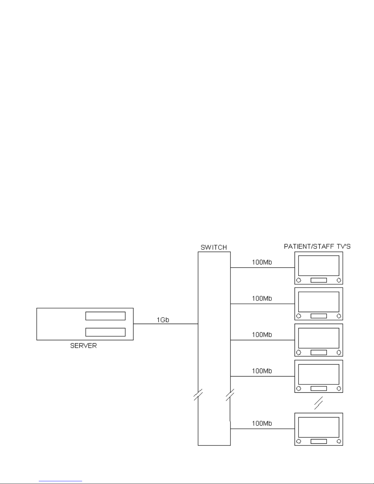
INTERNET PROTOCOL TELEVISION (IPTV)
INTRODUCTION
IPTV allows viewing of media files that contain movies, audio and pictures through an Ethernet connection. These files are
made available through a media server computer(
s) connected to the same network. The TV finds all available servers and then
locates usable files on those servers. File selection is handled by On-Screen menus. Menu selection is handled via the pillow
speaker, IR remote or front panel buttons.
IPTV’
s can be used with the following systems available from HCI.
1.
MediaLink
Play multimedia content from any UPnP server on the TV network
running Twonky
Media
Server software.
No control, monitoring or reporting.
2.
MedicCare
Push or Pull
(video on
demand)
content from MediaCare
servers. Allows control of TV,
monitoring , sending messages and reporting of TV activity.
3.
Thin
Client
Remote desktop for a Thin
Client server to run PC applications. Usually used for Internet
access.
4.
Innova TV E-
Commerce capabilities,
revenue generating Video on Demand
, education, service
Patient Portal recovery, surveys and access to hospital services and information.
5.
FACES
Video on Demand, Education on Demand, weather, news, HL7 integration to HIS, ser
vice
recovery, room control of lights, temperature and more.
In addition to Ethernet capabilities, HCI Generation II sets may also access media files using three USB ports or on an optional
internal hard drive. The USB ports can be used for flash drives, USB hard drives and many other devices
using IPTV
including
mouse and keypad for ThinClient use
.
TYPICAL BASIC IPTV SERVER SYSTEM
NOTE: Switch must have a 1Gb
connection to the server. TV’s require
100Mb connectio
n only.

--------------------------------------------------------------------------------------
GEN
II OPERATIONS MANUAL
HealthCare Information, LLC
39
IP
TV SETUP
General IP SETUP
IP MODE
:
Sets the set to use static (Manual) or automatic (DHCP) IP addresses. Sel
ections are:
Automatic(DHCP
) -
Manual
Automatic(DHCP)
TV automatically get IP address from DHCP server.
Manual
IP address is fixed
and is entered during IPTV setup.
NOTE: Each TV in a facility must have a unique IP address. Normal set
ting is Manual.
IP Address:
Static IP address of the TV. Press enter to set. Normal setting is 192.168.xxx.xxx.
NOTE: xxx can be any number between 1 and 254.
Subnet Mask: Sub
net mask of the TV. Press “ENTER”
to set. Normal setting is 255.
255.255.0
Gateway
IP address of the MediaCare or MediaLink server. Normal setting is 192.168.xxx.xxx.
Address
:
NOTE: xxx can be any number between 1 and 254.
MAC Address: Media Access Control address assigned to the TV’s network
interface. Can not be
changed.
Current IP:
Shows current IP address of the TV. Can not be changed.
Hard Disk Utility
Hard Disk
Checks and formats the hard disk for use in the TV. Selections are:
Utility:
Check File System – Format Hard Disk
Check File System
Checks to see if the hard drive is properly formatted.
Format Hard Disk
Formats the hard drive.
WARNING
Formatting the hard
drive will result
in all data stored on the hard drive
being lost. Hard drive should be form
atted only when first installed into an
HCI TV.
JPEG
Set JPEG decoding to be done by hardware or software. Selections are:
Decoding:
Software – Hardware
NOTE: Normal setting is for Hardware.
Picture timer: Determines how long each
picture is displayed on screen before advancing to the next
picture. Selections are:
5 sec – 10 sec – 15 sec – 20 sec – 25 sec
Firmware
Enables IPTV
operating system
upgrade via USB flash drive. Selections are
:
Upgrade:
Disable - Ena
ble
NOTE: Once new software has been installed setting will change to Disable.
Version:
Displays software version. Can not be changed.
UPNP Function Universal Plug and Play. Enables or disables UPNP function. Selections are:
Enable – Dis
able
NOTE: Must be enabled for MediaLink to function.

--------------------------------------------------------------------------------------
GEN
II OPERATIONS MANUAL
HealthCare Information, LLC
40
-- ThinC
lient Settings --
Server
IP address of the thin client server. Press enter to set. Normal setting is 192.168.xxx.xxx.
Address:
NOTE: xxx can be any number between 1 and 254.
Program
Selects the protocol used to connect to the thin client server. Selections are:
Select:
VNC – RDP – Citrix[ICA]
VNC
Linux remote desktop protocol.
RDP
Windows remote desktop protocol.
Citrix[ICA]
Citrix
(NOT SUPPORTED
AT THIS TIME)
NOTE: RDP is recommended for ThinClient applications.
Color Select: Selects the number of colors that can be displayed for ThinClient applications. Selections
are:
8 bits – 16 bits – 24 bits – 32 bits
NOTE: The higher
settings may result in slower ThinClient operation: Recommend setting
is 24 bits.
Auto Login: Enables or disables auto login when Remote Desktop is selected. Selections are:
Enable - Disable
Enable TV logins in to ThinClient server au
tomatically when remote desktop is selected.
Disable User must enter user name and password when remote desktop is selected.
U
sername
User name automatically entered whe
n Auto Login is enabled. Determined by static IP
address
.
Password
Pas
sword automatically entered when Auto Login is enabled.
Determined by static IP
address.
--
Home Page Settings --
Home Page
Setup allows the home page button
to be enab
led or disabled. Disabled button
s will not be visible on the
IPTV
home p
age screen.
See the MediaCare manual to setup directories on the MediaCare server. Folders on the hard
drive must be in the root directory.
Available buttons and function are:
Thin Client Button: –
Starts remote desktop s
ession on ThinClient Ser
ver.
TV must be connected to
a ThinClient server via the RF-45 Ethernet port on the rear jack panel.
Image Button: - Displays a list of
image
files located in the I
mages folder for MediaCare systems
or the
Picture folder if using an inte
rnal hard drive
.
Folder names are case sensitive.
If set is
connected to a MediaCare system
the Images directory will be on the MediaCare server
. If an internal
hard drive is
used
then the Picture folder
will be on the hard drive. If a MediaCare system is not
available or a hard drive is not installed, this button should be disabled.
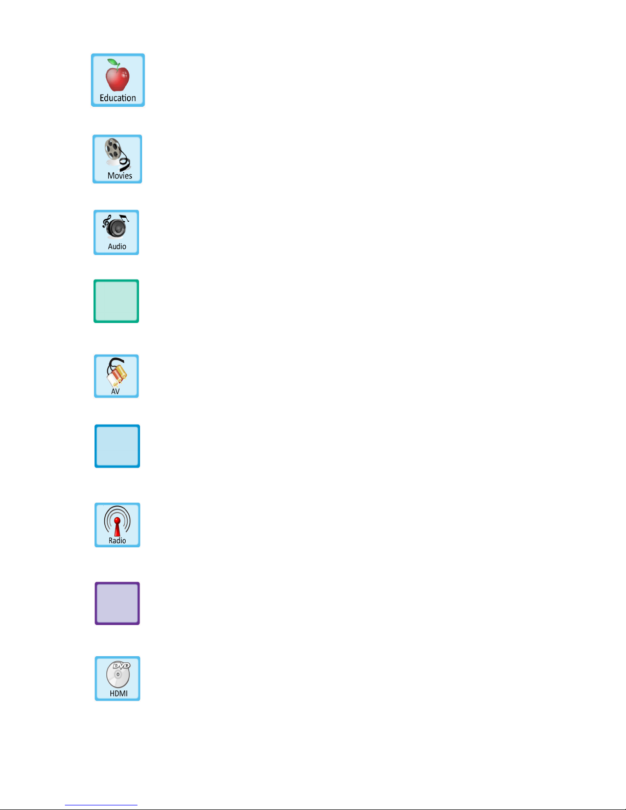
--------------------------------------------------------------------------------------
GEN
II OPERATIONS MANUAL
HealthCare Information, LLC
41
Education Button: - Displays a list of
movie or image
files located in the Education folder
. If set is
connected to a MediaCare system
the Education folder will be on the MediaCare server. If an
internal hard drive is
used
the Education directory will be on the hard drive. If a MediaCare
system is not available or a hard drive is not installed, this button should be disabled.
Folder names
are
case sensitive.
Movies Button - Displays a list of
movie
files located in the Movies folder for Media Care systems
or the
Video directory if using an internal hard drive.
If set is connected to a MediaCare system the
Movie folder
will be on
the MediaCare server. If an internal hard drive is used then the
Video
folder
will be on the hard drive. If a MediaCare system is not available or a hard drive is not
installed, this button should be disabled.
Folder names are case sensitive.
Audio
Button - Displays a list of
audio
files located in the Audio directory. If set is connected to a
MediaCare system the Audio folder
will be on the MediaCare server. If an internal hard drive is
used then the Audio folder
will be on the
hard drive. If a MediaCare system is not available or
a hard drive is not installed, this button should be disabled.
. Folder names are case sensitive.
Auto Play Green Button – This is a multi-function button. Selections are:
AV – Green – Disable
AV
Displays AV button. Switches set to AV input.
OR
Green
Plays the file named Green.mpg
located in the root directory of the
internal hard drive. Must have internal hard drive for this selection.
File name is case sensitive.
Disable No button displayed.
Auto Play Blue Button – This is a multi-function button. Selections are:
Radio – Blue – Disable
Radio
Displays Radio button. Switches set to FM input.
OR
Blue
Plays the file named Blue.mpg
located in the root directory of the
internal hard drive. Must have internal hard drive for this selection.
File name is case sensitive
Disable No button displayed.
Auto Play Purple Button – This is
a multi-function button. Selections are:
HDMI –
Purple – Disable
HDMI Displays HDMI button. Switches set to HDMI input.
OR
Purple
Plays the file named Purple.mpg
located in the root directory of the
internal hard
drive. Must have internal hard drive for this selection.
File name is case sensitive.
Disable No button displayed.

--------------------------------------------------------------------------------------
GEN
II OPERATIONS MANUAL
HealthCare Information, LLC
42
T
o enable or disable icons:
1.
Use the UP/DOWN arrow buttons to select the icon to be enabled or disabled.
2.
Press the RIGHT arr
ow button.
3.
Use the UP/DOWN arrow buttons to select EMABLE or DISABLE. Press the ENTER button.
4.
Repeat steps 1-4 as necessary to ENABLE or DISABLE other icons.
5.
When finished, press the LEFT arrow button to exit the Home Page Settings menu.
Once all of t
he IPTV settings have been entered, press the BACK button. The new settings will be saved and the IPTV
processor will reset to activate the new settings. The reset pr
ocess will take approximately 30 seconds
.
Automatic Buttons
The following buttons wil
l appear automatically when other devices or servers are connected to the set or found on the TV
network.
USB
Will appear when a USB flash drive is inserted in any of the USB ports on the set.
Prescribed
Lists images and videos found in
the
Prescribed folder for this set on a MediaCare server.
Media
Set must be connected to a MediaCare server. This button will not be available on sets using
an internal hard drive.
Local Media
Will appear when a hard drive is installed in
the set.
Media
Link
Will appear when a UPnP server is detected on the network. UPnP server(s) must be running
Twonky Vision media server software.
UPNP Function: must be enabled in the IPTV setup
m
enu for MediaLink to function.
TV
A
lways available. C
an not be disabled. Switches set
to TV mode.

--------------------------------------------------------------------------------------
GEN
II OPERATIONS MANUAL
HealthCare Information, LLC
43
USING IPTV
SETTING IP ADDRESSES
If you are not connecting the set to a network you do not need to set the IP address. Skip to IPTV operation on page 44.
If you are connecting to a n
etwork then each TV will have to be assigned a unique IP address. In addition you will need
to know the IP address of the media server or MediaCare server and the IP address of the ThinClient server if used. A
ThinClient server will allow a Remote Desk
top Session to access PC application such as Internet Explorer.
You will need an HCI IR remote control to set the IP address. After selections are made you must press the “ENTER”
for the change to be accepted. IP address are entered using the number b
uttons.
You will not see the IP address change
until you exit the setup menu and IPTV reboots. To check your
settings enter
setup again after the IPTV has rebooted.
1. Turn set on and press the IPTV button on an HCI IR remote.
2. Enter setup by pressing the
“FUNCTION” button then the “0” button on the IR remote.
3. When “CODE” appears on the upper right corner of the screen enter “9999”. Do not press setup. If setup is
pressed, press the “ENTER” button to remove the TV setup menu from the screen. The IPTV s
etup menu will
appear.
4. Press the right arrow button
5. IP MODE should be set to Manual. Change to manual if it is not.
6. Arrow down to IP Address, press the “ENTER” button and enter the assigned IP address for this set. Press the
“ENTER” button when finish
ed.
7. Press the down arrow button to select Subnet Mask.
8. Press the “ENTER” button and enter the Subnet Mask. Normal setting is 255.255.255.0. Press the “ENTER”
button when finished.
9. Press the down arrow button to select Gateway Address.
10. Press the “E
NTER” button and enter the Gateway Address. This is the IP address of your IPTV file server or
MediaCare server and NOT the ThinClient server.
11. Press the “ENTER” button.
12. Press the left arrow button and then the down arrow button twice to select Thinclien
t Settings.
Note: If you are not using a ThinClient server skip to IPTV operation on page 44.
13. Press the right arrow button then the down arrow button to select Server Address.
14. Press the “ENTER” button.
15. Enter the IP address of the Thin Client Server.
When finished, press the “ENTER” button.
16. Press the “BACK” button. The IPTV will reset. This will take about 30 seconds. When the IPTV has
rebooted you will see the IPTV home screen.
You can re-enter IPTV setup to check your settings.

--------------------------------------------------------------------------------------
GEN
II OPERATIONS MANUAL
HealthCare Information, LLC
44
IPTV OPERA
TION
1. To enter IPTV mode, press the IPTV button on an IR remote control or select IPTV from the source menu.
The source menu can be accessed using the Source button on the IR remote control, TV/AV button on the set
or the Input button on the set. Once
IP
TV has been selected, it may
take a few seconds for the IPTV software
to load and start.
2. Use the LEFT, RIGHT, UP and DOWN arrow buttons on the front panel (If available), IR remote or pillow
speaker (full digital required) to select the function you wish.
3. Press the “ENTER” button.
4. Once a source button is pressed the TV will change to that source. You will need to re-enter IPTV mode as
instructed in line 1 above.
5. If a media button is pressed, follow the on screen prompts to select the media file to view
or play.
6. Use the “BACK” button to return to the previous screen and the “HOME” button to return to the MAIN
MENU screen.
7. Pressing the status button on the IR remote when no media is playing or displayed will display the status of the
hard drive if insta
lled. Drive size, free space and used space will be displayed.
8. Pressing the status button when media is being played or viewed will display file information of the current
selection.
File name, file size, elapsed time (how long it has been playing), Len
gth and repeat mode will be
displayed.
CONTROLING MEDIA PLAYBACK
During play back you can use the colored arrow buttons on an IR remote to control play back as follows.
YELLOW
PAUSE
RED
FAST REVERSE
GREEN
FAST FORWARD
BLUE
STOP
CENTER BUTTON
PLAY
NOTE:
See page 36
for controlling playback using a digital pillow speaker.
1.
When the media file is finished playing or the stop button is pressed the TV will return to the file selection screen.
Press the “HOME button to return to
the main IPTV screen.
2.
Any time during the selection process you can press the BACK button to return to the previous menu or the HOME
button to return to the IPTV home screen.
3.
Selecting Repeat All will repeat all listed files until interrupted.
4.
Selecting
Play All will play all listed files once. Play can be interrupted.

--------------------------------------------------------------------------------------
GEN
II OPERATIONS MANUAL
HealthCare Information, LLC
45
HARD DRIVE FILE MANAGEMENT
All RoomMate Series GENII sets can be equipped with an optional hard drive that can be used to store Picture, Sound and
Video files for playback on the se
t.
To prevent illegal copies being made from contend stored on the hard drive it is not
possible to copy files from the hard drive to another source such as a USB flash drive.
Also, the hard drive can not be
accessed through the network port.
You will n
eed the following to access the hard drive for file management:
USB flash drive
or USB hard drive
with the content you wish to load on to the hard drive.
OR
1. PC or laptop running XP or Vista with access to the files you wish to place on the hard drive
.
2. Cat5e crossover cable
to connect computer directly to TV. If the TV is connected to a network, you can access the hard
drive by connecting your computer to the same network. A crossover cable will not be necessary.
3. IR remote control for TV.
4. TV IP ad
dress. See page 43
.
USB FLASH DRIVE/HARD
DRIVE
1.
Turn TV on and set the in
put source to IPTV.
2.
Insert or connect the USB drive to one of the U
SB ports on the TV. See pages
10 – 13.
3.
Select the USB button
and press the ENTER button
.
4.
Select the USB devic
e. USB devices are numbered according to the order they were plugged in to the
TV. Press the ENTER button.
5.
Select the file to be copied to the hard drive. Press the yellow PAUSE button.
6.
Select Yes and press the enter button. The file will be copied t
o the hard drive.
7.
When copy is finished, FINISH will be selected in the copy window. Press the “ENTER” button.
NOTE:
Video files will be copied to the VIDEO folder on the hard drive, audio files to the AUDIO folder and
picture files to the PICTURE fold
er. IF the folder does not exist a window will open
indicating a folder will be
created. Select FINISH and press the ENTER button.
PC OR LAPTOP
1. If connecting your PC directly to the TV, plug one end of a crossover cable into the RJ-45 jack of your PC and the other
end into the RJ-45 jack on the TV. If the TV is connected to a network, plug your PC into the same network with a
standard
CAT5e cable.
2. Turn the TV and computer on.
3. Set the input source of the TV to IPTV
.
CONNECTING TO WINDOWS XP
Windows
screens and icons may look different depending on display settings and update versions.
1.
Open the “My Network Places” folder.
2.
Open the “Add Network Place” folder. Click the “Next” button.
3.
Click on “Choose another network location”. Click the “Next”
button.
4.
Enter the IP address from step 7 above as shown. Do not enter leading zeros.
Example:
5.
Click the “Next” button.

--------------------------------------------------------------------------------------
GEN
II OPERATIONS MANUAL
HealthCare Information, LLC
46
6.
If the “Log on anonymously” box is checked, click on the box to uncheck it.
7.
Do not e
nter the user name.
Leave blank.
8.
The default name for this network place is the IP address. The default name is recommended.
You may
ch
ange the default name if you wis
h.
Click the “Next” button.
9.
Click the “Finish” button. Windows will create an icon in the “MY Net
work Places” with the IP address name
and open a connection to the TV.
10.
A window will open asking for a
user name and password.
For early versions of software e
nter
user name
“hciadmin” and
password “ftphciadmin”.
For l
ater versions of software enter use
r name “hci” and password
“1981”.
If you want windows to remember the password for this connection, click on the “Save password”
box to check it.
11.
Click the “Log On” button.
12.
A screen will open with two folders. Open the “hdd” folder. This
is the hard drive in the set. You may create
folders and drag content file to the “hdd” folder.

--------------------------------------------------------------------------------------
GEN
II OPERATIONS MANUAL
HealthCare Information, LLC
47
DO NOT STORE FILES OR CREATE FOLDERS IN THE “b
in” FOLDER
.
13.
When finished transferring content, close the ftp window and disconnect the Cat5e cables.
14.
Repeat
this for all TV’s you wish to transfer content to.
Note: If your TV’s are not connected to a network you can set all the IP address’s the same and use the same
network fo
lder for all sets. See Page 43
.
15.
Once you have created an FTP folder in the “My Network Places” folder you can transfer content as follows.
A.
Connect your computer to the TV using a crossover cable.
B.
Turn TV on and change to IPTV mode.
C.
Open the “My Network Places” folder.
D.
Open the folder named with the IP address of the TV you wish to acce
ss.
E.
Enter user name and password. Current software User Name = hci and Password = 1981. For older
versions of software User Name = hciadmin and Password = ftphciadmin.
F.
You can create and Delete folders and transfer files to and from the hard drive and delete files.
CONNECTING TO WINDOWS VISTA
a. Open the “COMPUTER” folder.
b. Right click one and open area of the “COMPUTER” window.
c. Click on Add a Network Location. Click the “Next” button.
d. Click on “Choose a custom network location”. Clic
k the “Next” button.
e. Enter the IP address as follows. Do not enter leading zeros.
Example
f. If the “Log on anonymously” box is checked, click on the box to uncheck it.

--------------------------------------------------------------------------------------
GEN
II OPERATIONS MANUAL
HealthCare Information, LLC
48
g. Do not e
nter t
he user name.
h. The default name for this network place is the IP address. The default name is recommended.
You may
change the name if you wish.
i. Click the “Finish” button. Windows will create an icon in the “Computer” folder with the IP address name and
open a connection to the TV.
j. A window will o
pen asking for a
user name
password.
For early versions of software enter user name
“hciadmin” and
password “ftphciadmin”.
For later versions of software enter user name “hci” and password
“1981”.
If you want windows to remember the password for this co
nnection, click on the “Save password”
box to check it.
k. Click the “Log On” button.
l. A screen will open with two folders. Open the “hdd” folder. This is the hard drive in the set. You may create
folders and drag content files to the “hdd” fo
lder
DO NOT STORE FILES OR CREATE FOLDERS IN THE “bin” FOLDER
.
m. When finished transferring content, close the ftp window and disconnect the Cat5e cables.
n. Repeat this for all TV’s you wish to transfer content to.
Note: If your TV’s are not connected to
a network you can set all the IP address’s the same and use the
same network f
older for all sets. See page 43
.
o. Once you have created an FTP folder in the “My Network Places” folder you can transfer content as follows.
1. Connect your computer to the TV us
ing a crossover cable.
2. Turn TV on and change to IPTV mode.
3. Open the “Computer” folder.
4. Open the folder named with the IP address of the TV you wish to access.
5. Enter user name and password. Current software User Name = hci and Password = 1981. For older
v
ersions of software User Name = hciadmin and Password = ftphciadmin.
6. You can create and Delete folders and transfer files to and from the hard drive and delete files.

--------------------------------------------------------------------------------------
GEN
II OPERATIONS MANUAL
HealthCare Information, LLC
49
COPYING FILES FROM USB DEVICE TO HARD DRIVE
You may copy media files from any supported USB mass storage device to the optional hard drive. Files can only be
copied on at a time. To copy files;
1. Connect the USB mass storage device to the TV.
2. Select the file as if you were going to play o
r display the file.
Do not start the file playing
.
3. Press the “YELLOW” button on the IR remote. A “Copy Function” window will open on the left side of the
screen.
File name and destination will be displayed in the window.
4. Use the Left/Right arrow buttons to select “Yes”. Press the “ENTER” button. If
there is not enough room on
the hard drive “Device not exist or full disk” will be displayed in the window. Copying will not be possible.
5. The file will be copied
to the proper folder. Movies will be copied to the Video folder, Audio to the Audio
folde
r and Images to the Picture folder. If the folder does not exist in the root directory, it will be created in the
root directory. For proper operation the Video, Audio and Picture folders MUST be in the root directory.
6. To copy files to the Education fo
lder you must use an FTP connection. See pages 45-48. You must create and
Education folder in the root directory if one does not already exist. The Education folder must be in the root
directory of the hard drive.
NOTE: To protect copyrighted material
you can not copy files from the hard drive to a USB device.
The hard
dr
ive can not be accessed from the network.
DELETING FILES FROM THE HARD DRIVE
1. Select the file you wish to delete as if you were going to play or view the file. Do not press the pl
ay button.
2. Press the Blue button on the remote. A “Delete Function” window will open on the left side of the screen.
3. Use the Left/Right arrow buttons to select “Yes”. Press the “ENTER” button.
4. The file will be deleted and the media list will be refre
shed.
NOTE: Copying files from the USB drive to the hard drive is the fastest method but only one file can be copied at
a time. Using an FTP connection is slower but you can select multiple files and/or folders. Once the copy process
is started you c
an allow it to run unattended.

--------------------------------------------------------------------------------------
GEN
II OPERATIONS MANUAL
HealthCare Information, LLC
50
ROOMMATE SERIES SETUP MENU TREE

--------------------------------------------------------------------------------------
GEN
II OPERATIONS MANUAL
HealthCare Information, LLC
51
PARENTAL CONTROL
TV RATINGS
United States
TV
-Y
Content appropriate for all ages.
TV-Y7
Content may not be suitable for children under 7 years of age.
TV-Y7-FV
Conte
nt may not be suitable for children under 7 years of age. Contains
fantasy violence.
TV
-G
General Audiences
TV-PG
Content may not be suitable for young children
V
Moderate Violence
S
Mild Sexual Situations
L
Mild Coarse Language
D
Sugges
tive Dialogue or Drama
TV
-14
Content may not be suitable for children under the age of 14.
V
Intense Violence
S
Moderate Sexual Situations
L
Coarse Language
D
Highly Suggestive Dialogue
TV-MA
Content intended for mature
audiences only.
Canadian Ratings
C
Content suitable for children under 8 years of age. No profanity or sexual
content. Minimal comedic violence.
C8
Content suitable for children over 8 years of age. No profanity.
Occasional “socially offensi
ve and discriminatory” language allowed if in
the content of the story. Little or no sex or nudity.
G
Content suitable for the entire family. Minimal violence, no profanity or
sexual content.

--------------------------------------------------------------------------------------
GEN
II OPERATIONS MANUAL
HealthCare Information, LLC
52
PG
Parental guidance suggested. Moderate violence, mi
ld profanity, brief nudity
and sexual references allowed if important to the story line.
14+
Content intended for viewers over 14 years of age.
18+
Content intended for viewers over the age of 18. May contain strong violence,
language and sexu
al activity
.
Quebec Ratings
G
Content appropriate for all ages. Little
or no violence or sexual content.
8+
Content appropriate for children over the age of 8. May contain little violence,
some foul language and little or no sexual content
.
13+
Content appropriate for teenagers over the age of 13. May contain moderate
violence, language and some sexual situations. Children under the age of 13
should be accompanied by an adult
.
16+
Content appropriate for teenagers over the age of 16. May cont
ain strong
violence, language and sexual content
.
18+
Content for adults over the age of 18 only. May contain extreme violence,
graphic sexual content and pornography
.
E
Exempt programming. No rating will appear on screen
.
Setup
1.
En
ter the setup men
u. See page 17.
2.
Go to the ADVANCE MENU and select PARENT CONTROL. Press the right arrow button
.
3.
Enter password. Default password is “0000”.
4.
Select CHANGE PASSWORD if you wish to change the password. Follow the on-screen prompts to
change the passwo
rd
.
5.
Select V-CHIP and set to ON. Use the right arrow button to change
.
6.
Select TV RATING. Press the right arrow button
.
7.
Use the arrow buttons to select rating levels Press the B button to block or unblock each rating. Some
rating will effect the rati
ng below them. Press the ENTER button when finished
.
8.
Select MOVIE-RATING. Use the right arrow button to select the highest rating you wish to allow. The
selected rating and all ratings below will be allowed. All rating above will be blocked
.
9.
Select E
NGLISH-RATING. Use the right arrow button to select the highest rating you wish to allow. The
selected rating and all ratings below will be allowed. All rating above will be blocked
.
10.
Select FRENCH-RATING. Use the right arrow button to select the highe
st rating you wish to allow. The
selected rating and all ratings below will be allowed. All ratings above will be blocked
.

--------------------------------------------------------------------------------------
GEN
II OPERATIONS MANUAL
HealthCare Information, LLC
53
KEY DEFINE
The functions of the front or side panel buttons can be redefined. To change the functions
:
1.
Select KEY DEFINE in the
SYSTEM menu and press the right arrow button.
2.
Select the button you wish to change. Not all buttons can be changed. See diagram for button locations.
Later
version keypads may be labeled differently but the location is the same.
3.
Use the right and lef
t arrow button to change the function.
4.
Repeat steps 2 and 3 for all buttons you wish to change.
5.
Press the ENTER button when finished.
MODELS
WITH FRONT PANEL KEYPAD.
MODELS
WITH SIDE PANLE KEYPAD ONLY.
NOTE: K
eypad mapping is the same regardless of the key
label
.

--------------------------------------------------------------------------------------
GEN
II OPERATIONS MANUAL
HealthCare Information, LLC
54
DIGITAL TV SETUP
Digital broadcasts offer clearer pictures and allow the broadcast of several channels on one channel. Data is included in the
broadcast to identify all channels. Channels are identi
fied by the major channel number and then the sub-channel number. The
format is XX.YY where XX is the major channel number and YY is the sub-channel number.
All HCI sets use the “BACK”
button for the “.”
There are two types of digital TV
signals. The f
irst is broadcast over the air by local television stations. These signals are know
as ATSC or 8VSB. ATSC signals are not broadcast
on the sam
e RF frequency as the standard analog signal. The signal
contains extra data in addition to the audio/video dat
a stream. This extra data identifies the major channel
and sub-channels.
ATSC signals can have up to six sub-channels.
EXAMPLE
Channel 48 in Cincinnati Broadcast its analog channel on UHF channel 48 and its digital channel on UHF channel
34 and has
two
digital channels or sub-channels. The channels are displayed as 48.1 and 48.2. In most digital broadcasts, the first sub
channel will be the digital version of the analog broadcast. It is not necessary for the operator/user to know the RF channel and
t
his information is not available on screen.
The second type of digital broadcast is used by cable companies. This is called QAM. QAM channels are identified by major
channel number and sub channel number just like ATSC broadcasts but QAM channel may hav
e more than one
major channel
and corresponding
sub-channels. QAM channels can also contain 10 or more digital channels.
There are two types of QAM
channels currently in use. QAM 64 and QAM 256. QAM 256 can carry more channels on a single RF channel.
EX
AMPLE
RF channel 84 on Cincinnati cable has major channel 5 with two sub-channels and major channel 54 with four sub-channels.
The channels are displayed as 5.1, 5.2 and 54.1, 54.2, 54.3, 54.4. As with ATSC, it is not necessary to know the RF channel
number. The RF channel number is not available on screen.
HIGH
DEFINITION
(HD)
Not all digital broadcasts are High
Definition. Many digital broadcasts are Standard
Definition
(SD). SD broadcast are still far
superior to analog broadcasts and many people mistake them for HD. HD broadcasts take up more bandwidth and reduce the
number of sub-channels a given RF channel can carry
.
TV SETUPS
Off Air Digital
Cable
Digital
ATSC SOURCE
8VSB
QAM
ATSC MODE
AIR 8VSB
CABLE 64 or CABLE 256
Note: M
ost cable companies use QAM 256.
For facilities that convert off air channels to cable channels (CATV) without changing
the digital format to QAM the settings
would be:
ATSC SOURCE
QAM
ATSC MODE
AIR 8VSB

--------------------------------------------------------------------------------------
GEN
II OPERATIONS MANUAL
HealthCare Information, LLC
55
BANKS
The RoomMate series sets have four bank
s (also know as tiers) to store active channel lists in. The selected bank determines
what channels the patient can view. When an auto scan is preformed all channels that are found are set to active in BANK 1.
The default bank is BANK1. Using the bank
edit function, the active channels can be enabled or disabled in each bank. Banks
can also be copied from one to another. All channels in a bank can also be completely cleared or set.
Atypical use for banks would be for a simple rental system. Bank 1 c
ould have only free and patient education channels active.
Bank 2 could have free, basic and patient channels active, bank 3 could have free, basic, premium and patient channels active
and bank 4 could have only staff channels active. In this way a single distribution system can deliver all channels to each TV but
only the active channels in the selected bank can be viewed on the TV.
EDITING BANKS
1.
Enter the
SETUP menu. See pages 17.
2.
Select BANK EDIT under the SOURCE SETUP menu. See page 31.
3.
Press
the right arrow button to enter the bank-editing screen.
4.
Use the up and down arrow buttons to select the channel you wish to change.
5.
Use the right and left arrow buttons to select which bank you wish to change.
6.
Press the B button to toggle the channels
status. A check mark indicates active and a box indicates inactive.
7.
Repeat steps 3-5 for all channels you wish to change.
8.
To copy a bank use the left and right arrow keys to select the bank you wish to copy from. The channel
selection does not matter. Press the yellow key. Use the left and right arrow keys to select the bank you wish
to copy to and press the yellow button again.
9.
To clear a bank, use the left and right arrow keys to select the bank you wish to clear. The channel selection
does not ma
tter. Press the red button. All channels in that bank will be set to inactive.
10.
To set a bank, use the left and right arrow keys to select the bank you wish to clear. The channel selection does
not matter. Press the dark green button. All channels in
that bank will be set to active.
11.
To edit the DTV press the home button and follow the above instructions.
12.
When finished, press the ENTER or ESC button to exit the bank edit screen.
COPY BANK
1.
Use the arrow buttons to place the curser on any channel in t
he Bank you wish to copy.
2.
Press the Yellow
button
.
3.
Use the arrow buttons to place the curser on any channel in the Bank you wish to copy to.
4.
Press the Yellow Button again.

--------------------------------------------------------------------------------------
GEN
II OPERATIONS MANUAL
HealthCare Information, LLC
56
RESET BANK
1.
Use the arrow buttons to place the curser on any channel in the Bank
you wish to reset.
2.
Press the red button. All channels in the selected bank will be set to active.
CLEAR BANK
1.
Use the arrow buttons to place the curser on any channel in the Bank you wish to clear.
2.
Press the Green button. All channels in the selected bank will be set to inactive.
HDTV BANK EDITING
1.
Perform an AUTO SCAN f
or HDTV channels. See page 31
.
2.
Ente
r BANK EDIT mode. See page 31
.
3.
Press the “HOME” button.
4.
Edit HDTV banks sam
e as analog banks. (See Page 55 and 56
)
NOTE: You must perform a
n HDTV auto scan before editing the HDTV banks. You cannot add channels that were
not found during the AUTO SCAN process.
UNIVERSAL REMOTE OPERATION
IR Bands 3 and 4 are for Universal Remote operation.
Band 3 is for Magnavox
code
s. Band 4 is for Apex codes. Both of these
codes are common to most universal remotes. Follow the instructions for your universal remote to set the remote for one of
these codes.
Not all function may be available on all universal
remotes.
The following universal remotes hav
e been tested and known to work.
All universal remotes should have a code setting that will
work in Band 3 and/or Band 4.
SOFTWARE UPDATES
Up dating the operating software for the RoomMate Series of set requires special hardware prog
rammers, software and a PC or
Laptop running Windows XP. A kit containing all necessary hardware (PC or laptop not included), software and instructions is
available through your dealer. Software updates can be obtained through your dealer or HCI.

--------------------------------------------------------------------------------------
GEN
II OPERATIONS MANUAL
HealthCare Information, LLC
57
DVD PLAYER
ACCESSO
RIES
ALL AXIS MOUNT
FULL SWING WALL MOUNT
TABLE MOUNTS
VISITOR STATION
DUAL PILLOW SPEAKER INTERFACE
HARD DRIVE
CEILING MOUNT
DVD MOUNTS
MEMORY MODULE
KEYBOARDS AND MICE
PIPE MOUNTS

--------------------------------------------------------------------------------------
GEN
II OPERATIONS MANUAL
HealthCare Information, LLC
58
SPECIFICATIONS
DIMENSIONS RM20II

--------------------------------------------------------------------------------------
GEN
II OPERATIONS MANUAL
HealthCare Information, LLC
59
DIMENSIONS RM22II
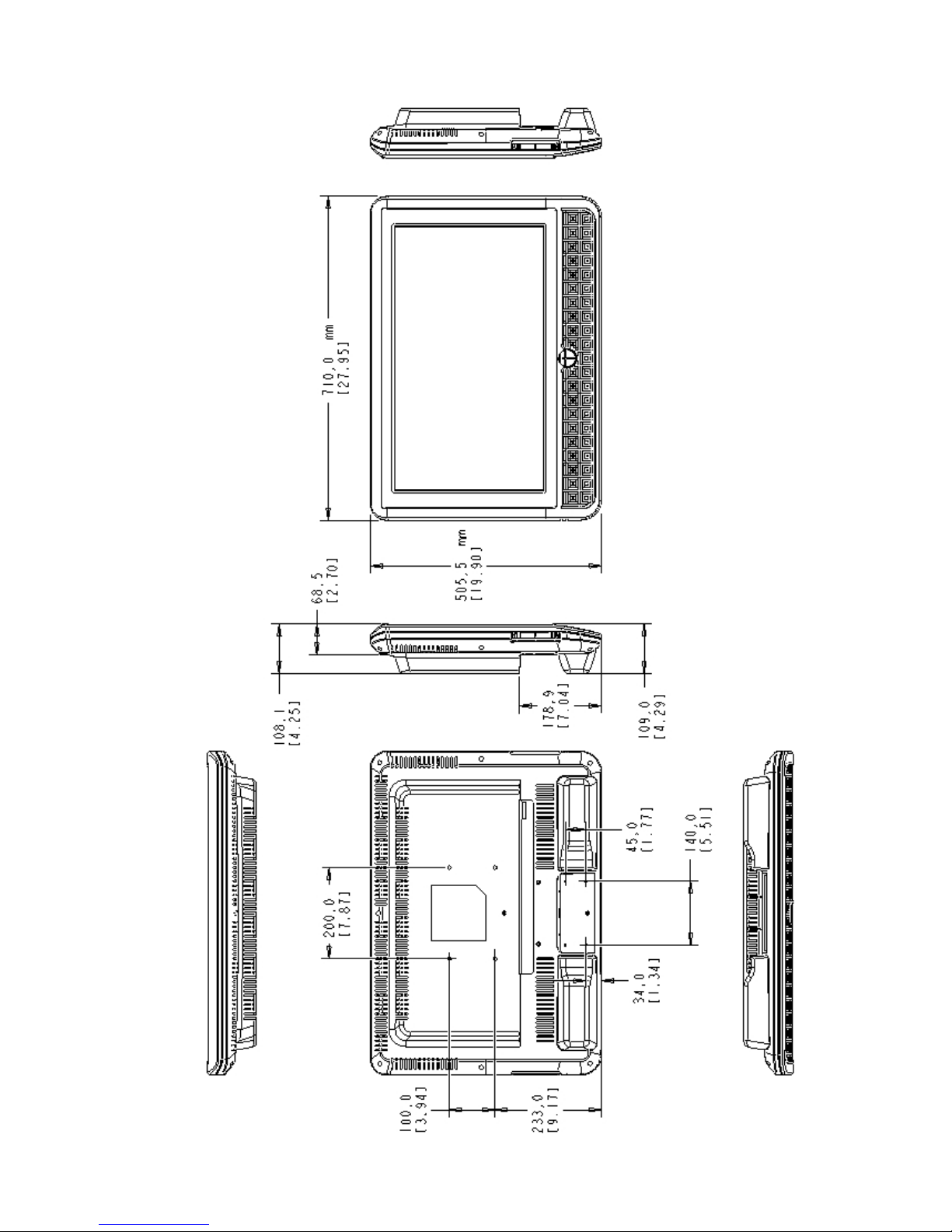
--------------------------------------------------------------------------------------
GEN
II OPERATIONS MANUAL
HealthCare Information, LLC
60
DIMENSIONS RM26II

--------------------------------------------------------------------------------------
GEN
II OPERATIONS MANUAL
HealthCare Information, LLC
61
DIMENSIONS RM32II

--------------------------------------------------------------------------------------
GEN
II OPERATIONS MANUAL
HealthCare Information, LLC
62
DIMENSIONS RM42II

--------------------------------------------------------------------------------------
GEN
II OPERATIONS MANUAL
HealthCare Information, LLC
63
DIME
NSIONS RM52II

--------------------------------------------------------------------------------------
GEN
II OPERATIONS MANUAL
HealthCare Information, LLC
64
GENERAL SPECIFICATIONS

--------------------------------------------------------------------------------------
GEN
II OPERATIONS MANUAL
HealthCare Information, LLC
65

--------------------------------------------------------------------------------------
GEN
II OPERATIONS MANUAL
HealthCare Information, LLC
66
WARRANTY
HCI warrants, to the original purchaser only that all ne
w HCI televisions (excluding any equipment manufactured by others and
included in HCI shipment) are free from defects in material for a period of two years from the date of shipment.
The dealer your product was purchased through must receive notice of a d
efect or malfunction occurring during the warranty
period, HCI will repair or replace goods returned to its Loveland, Ohio office, at its discretion, free of charge to the original
purchaser, the whole or any component part of any product manufactured by H
CI found to be defective.
As a condition to obtaining warranty service, notification must be given to the dealer the product was purchased through within
at least 10 days after defect is first observed. Repair of product requires it to be shipped to HCI in Loveland, Ohio. All shipping
and freight charges to HCI shall be paid for by the customer and will not be accepted without a Return Authorization Number
(RA#). The dealer can provide you information on how to obtain the RA#.
This warranty does not ap
ply to any HCI products subjected to improper use, negligence or accident; nor to tampering,
alterations, or repairs by others, without HCI’s written prior notice. For more information pertaining to this warranty, please
contact the dealer you purchased y
our product from.
HCI’s liability under this warranty is limited to repair or replacement of defective products and parts as
provided above. HCI shall not be liable for incidental or consequential damages.


HealthCare Information, LLC
113 Commerce Blvd.
Loveland, OH 45140
800-783-8105
www.hci-tv.com
©Copyright 2009, HealthCare information, LLC
 Loading...