

H.C Duke & Son Electro-Freeze Genesis Series, GEN-2080 Operator’s Manual With Illustrated Parts List

OPERATOR’S MANUAL
with Illustrated Parts List
Combination Soft Serve and
Shake Freezer
Model GEN-2080
185240— 4/15
H.C. Duke & Son, LLC. P/N 185240 April 2015 Printed In U.S.A.


Operator’s Manual
for
Electro Freeze Combination
Soft Serve and Shake
Freezer Model GEN-2080
All contents © Copyright 2015 H.C. Duke & Son, LLC., 2116 Eighth Avenue, East Moline, Illinois 61244
HC185240
i
ELECTRO FREEZE Soft Serve Model GEN-1578
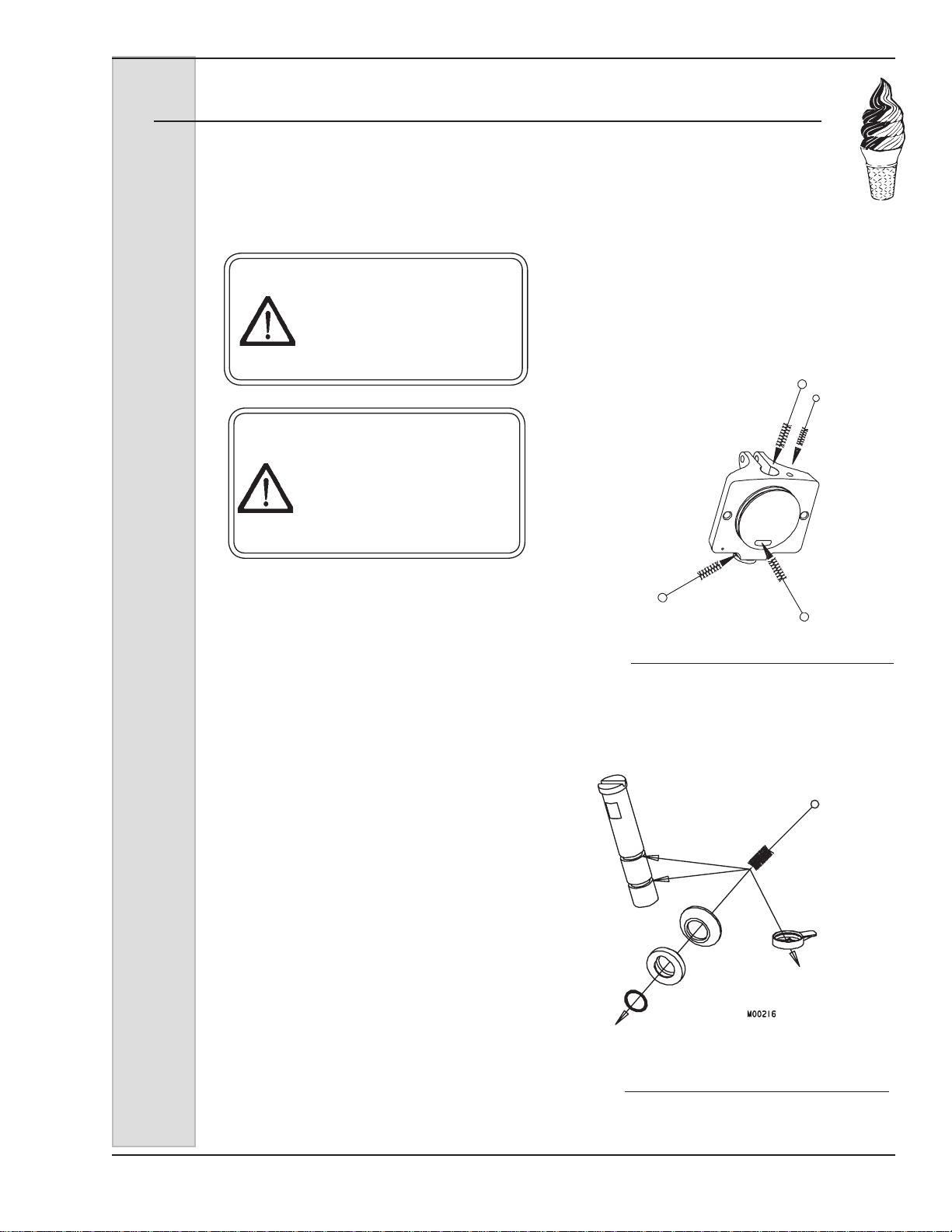
SAFETY FIRST!
Follow these four steps to safety ....
1. Recognize Safety Information ....Look for
this safety alert symbol throughout this manual.
When you see this symbol on your freezer or in this
manual, be alert to the potential for personal injury.
Follow recommended precautions and safe operating
practices.
2. Understand Signal Words ....
The signal words — DANGER, WARNING and
DANGER
WARNING
CAUTION
CAUTION — are used with the safety alert symbol
(DANGER decals on the freezer may or may not
have the safety alert symbol, but the message is the
same). Decals with the words DANGER, WARNING
or CAUTION appear on the freezer. DANGER
identies the most serious hazard. Decals with the
words DANGER or WARNING are typically near
specic hazards on the freezer. General precautions
are listed on CAUTION safety decals. In this manual,
CAUTION messages with the safety alert symbol
call attention to safety messages.
ii
ELECTRO FREEZE Soft Serve Model GEN-1578
Safety
First!
SAFETY FIRST!
3. Follow Safety Instructions ....
Read and understand all safety messages in this
manual. Read and understand the decal safety
messages on your freezer. Take notice of the location
of all decals on the freezer and keep the safety decals
in good condition. Check them periodically and replace
missing, damaged or illegible safety decals. The safety
decals must remain in place and legible for the life of
the freezer. If you need new decals, use the information
and illustrations on pages v and vi of this manual to
identify the decal and contact your local Electro Freeze
Distributor — or call or write to H.C. Duke & Son, LLC.
DO NOT attempt to operate the GEN-2080 freezer until
you read and understand all safety messages and the
operating instructions in this manual.
4. Operate Safely ....
DO NOT allow untrained personnel to maintain or
service this machine. Failure to follow this instruction
may result in severe personal injury. DO NOT operate
the freezer unless all service panels and access doors
are secured with screws. DO NOT attempt to maintain
or repair the freezer until the main power supply has
been disconnected. Some freezers have more than one
disconnect switch. Contact your local Electro Freeze
Distributor for authorized service.
iii
ELECTRO FREEZE Soft Serve Model GEN-1578
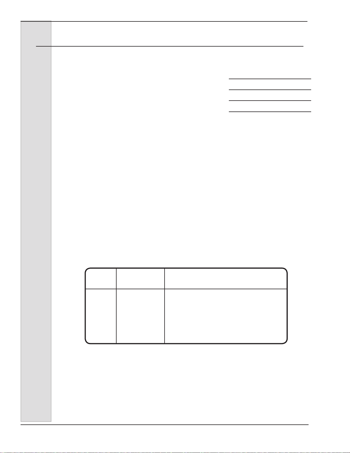
Safety Decal Locations
Do not attempt to operate the freezer
until all safety precautions and operating
instructions in this manual are read and
understood.
Take notice of all warning, caution,
instruction and information decals (or
labels) on the freezer as shown in the
gure to the right. The labels have been
put there to help maintain a safe working
environment.
The labels have been designed to withstand washing and cleaning. All labels
must remain legible for the life of the
freezer. Check labels periodically to be
sure they can be recognized as warning
labels.
If it is necessary to replace any label,
please contact your local authorized
Electro Freeze Distributor or H. C. Duke
& Son, LLC. When ready to order, you will
need to determine the (1) part number,
(2) type of label, (3) location of label, and
(4) quantity required, and include a return
shipping address.
You may contact your local authorized
Electro Freeze Distributor, as follows:
Name:
Address:
Phone:
or, for factory service assistance, contact
H. C. Duke & Son, Electro Freeze Service
Department by phone, FAX or e-mail:
Phone: (309) 755-4553
(800) 755-4545
FAX: (309) 755-9858
E-mail: service@hcduke.com
(The decals on the next page are
numbered 1, 2, 3 and 4. Those numbers
correspond to the numbers in the table
below. The table provides the part
number, description, and quantity for each
decal.)
No. Part No. Description (Qty)
1 HC165025 Decal — Beater Warning (1)
2 HC165246 Decal — Pressurized System Warning (2)
3 HC165048 Decal — Warning Rotating Parts (2)
4 HC165126 Decal — Panel Removal Warning (3)
iv
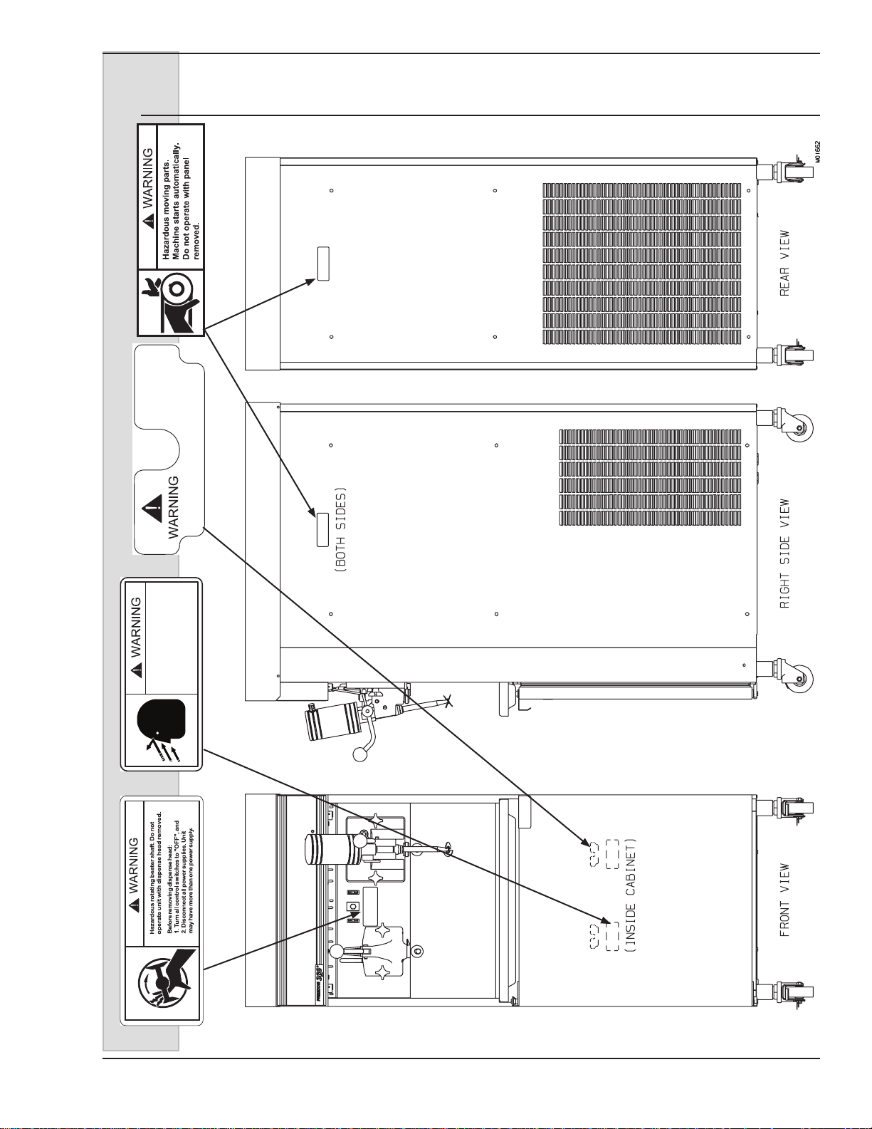
ELECTRO FREEZE Soft Serve Model GEN-2080
165048
Safety Decal Locations
HC165126
4
Do not
operate
with cover
removed!
Pressurized system.
Depressurize unit
before dismantling mix
HC165048
3
transfer system.
HC165246
2
HC165025
1
185240 vii

ELECTRO FREEZE Soft Serve Model GEN-1578
Table of Contents
Safety First ................................................................................................... ii
Safety Decal Locations ................................................................................... iv
Part I
1 Introduction ......................................................................... 1
2 Note to Installer ................................................................... 1
2.1 Uncrating and Inspection ............................................................. 2
2.2 Installation .................................................................................... 2
2.3 Electrical Requirements ............................................................... 3
2.4 Electrical Connections ................................................................. 3
3 Specications ...................................................................... 4
3.1 Particulars .................................................................................... 4
3.2 Installation Date ........................................................................... 4
3.3 Data Plate .................................................................................... 5
3.4 Reference Information ................................................................. 5
3.5 Dimensions .................................................................................. 6
4 Part Names and Functions — Soft Serve ............................ 8
5 Part Names and Functions — Shake .................................. 14
6 Operator Controls ................................................................ 18
7 Operator Display Menu ................................................................. 21
8 Disassembly and Cleaning — Soft Serve ............................ 24
8.1 Cleaning Accessories ................................................................... 25
8.2 Disassembly Instructions ............................................................. 26
8.3 Cleaning Instructions ................................................................... 29
8.3.1 Cleaning & Lubricating MTS Assembly ...................................... 31
9 Disassembly and Cleaning — Shake .................................. 33
9.1 Cleaning Accessories ......................................................... 34
9.2 Disassembly Instructions ............................................................. 36
9.3 Cleaning Instructions ................................................................... 37
9.3.1 Cleaning and Lubricating MTS Assembly .................................. 39
vi

ELECTRO FREEZE Soft Serve Model GEN-1578
Table of Contents — continued
10 Assembly — Soft Serve ....................................................... 40
11 Assembly — Shake ..................................................................... 45
12 Start-up Instructions — Soft Serve ........................................... 51
12.1 Sanitizing Instructions ................................................................ 51
12.2 Priming ....................................................................................... 52
13 Start-up Instructions — Shake ............................................ 53
13.1 Sanitizing Instructions ................................................................ 54
13.2 Priming ....................................................................................... 55
14 Closing Procedures ............................................................. 56
14.1 Night Switch Operation ............................................................... 56
14.2 Draining Product ......................................................................... 56
15 Product Information ............................................................. 58
15.1 Overrun ...................................................................................... 58
15.2 Overrun Adjustment .................................................................... 59
15.3 Rerun .......................................................................................... 59
16 Routine Maintenance ........................................................... 60
17 Troubleshooting Table ......................................................... 66
18 VQM Error Codes ................................................................ 75
Part II
Model GEN-2080 Replacement Parts Manual with Illustrations ............ *
* Refer to Part II Table of Contents
vii


ELECTRO FREEZE Soft Serve Model GEN-2080
1 Introduction
The GEN-2080 Freezer is designed to
produce soft serve ice cream, ice milk,
yogurt, and similar frozen dairy products,
with a product serving temperature range
of 15 to 25°F (-9 to -4°C). It also produces
shakes with a product temperature of
26°F (-3°C). If such products are prepared
from powdered concentrate, they should
be precooled to 40ºF (4°C) prior to
introduction to the freezer. Use of other
products in this machine is considered
misuse (see Warranty).
This manual has been prepared to assist
you in the proper operation and general
maintenance of the Electro Freeze Soft
Serve and Shake Freezer Model GEN-
2080.
Your freezer will not compensate for or
correct any assembly or priming errors
made during the initial start-up. Therefore,
it is important to follow the assembly
and priming procedures detailed in this
manual.
Make sure all personnel responsible for
equipment operation completely read and
understand this manual before operating
the freezer. When properly operated and
maintained, the freezer will produce a
consistent quality product.
If you require technical assistance, please
contact your local authorized Electro
Freeze Distributor as follows:
Name:__________________________
Address: ________________________
________________________________
Phone: __________________________
For factory service assistance — contact
H. C. Duke & Son, LLC., Electro Freeze
Service Department as follows:
Phone: (309) 755-4553
(800) 755-4545
FAX: (309) 755-9858
2 Note to Installer
This freezer must be installed and serviced by an Electro Freeze Distributor or
authorized service technician.
After installation the warranty registration card must be completed and
returned to validate the warranty.
E-mail: service@hcduke.com
185240 1

ELECTRO FREEZE Soft Serve Model GEN-2080
2.1 Uncrating and Inspection
Be sure to properly support
the machine when removing
bolts and installing legs or
casters.
CAUTION
When the unit is received and while
the carrier is still present, inspect the
shipping carton for any damage that
may have occurred in transit. If the
SHOCKWATCH® label indicates red and/
or the carton is broken, torn, or punctured,
Figure 2-1 Machine Bolted to Shipping Base
note the damage on the carrier’s freight
bill and notify the carrier’s local agent
immediately.
1. Remove the carton from the
pallet, and move the machine as close as
possible to the permanent location.
2. Remove the shipping bolts on
the bottom of the freezer (gure 2-1) and
install either the legs or casters (gure
2-2).
NOTE: Screw casters
or legs all the way in
coupling, then adjust
out to level side to side
with a 1/4” slope to the
front.
Figure 2-2 Installing Mounting Legs or Casters
2.2 Installation
CAUTION
All materials and connections
must conform to local
requirements and be in
compliance with the National
Electrical Code (NEC).
2 185240
1. This freezer is designed for indoor
use and must be protected from outdoor
weather conditions.
– continued

ELECTRO FREEZE Soft Serve Model GEN-2080
2.2 Installation (continued)
2. Where codes permit, we
recommend that the freezer be installed
on casters and have exible water and
electrical connections for service and
cleaning ability.
3. All models require a minimum 6
inch (15 cm) clearance on either the side
panels or the rear panel for adequate
ventilation. Freezers designed with top air
discharge require that at least 18 inches
(45 cm) above the top panel be free of
obstructions. Anything blocking ventilation
of the freezer (including cone dispensers)
will reduce the efciency of the freezer.
4. Water cooled models will require
a 1/2 inch MPT water inlet and water
waste connection. Both condensers are
2.3 Electrical Requirements
CAUTION
To prevent accidental electrical shock, a
positive earth ground is
required.
1. Always verify electrical
specications on the data plate of each
freezer. Data plate specications (see
Figure 3-1) will always supersede the
information in this manual.
tied together so that one water inlet and
one water waste is all that is required.
The connections are found on the bottom
under the compressor mounting area
and are tagged “Water Inlet” and “Water
Waste.” A manual shut-off valve should be
installed in the water inlet line at the time
of installation. The water pressure must
be above 35 psig (241 kPa) and below
140 psig (965 kPa) for proper operation.
5. Place the freezer in the nal
location and level by adjusting the legs or
casters so that it is level side-to-side and
the front is approximately ¼ inch lower
than the rear (to allow proper drainage of
the freezing cylinder).
2. Supply voltage must be within
+ 10% of voltage indicated on the
nameplate. Also, on three-phase
systems, voltage between phases must
be balanced within 2%. (More than a 6
volt difference between any two voltage
measurements at 208-230 volts indicates
a possible imbalance.) Request your local
power company to correct any voltage
problem.
3. An easily accessible main power
disconnect must be provided for all poles
of the wiring to the freezer.
2.4 Electrical Connections
CAUTION
To prevent accidental electrical shock, a positive earth
ground is required.
1. Double freezers with two
compressors require one power supply for
each side of the freezer. Each side of the
freezer operates independently.
2. Check the data plate for fuse
size, wire ampacity and electrical
specications.
185240 3
3. Refer to the wiring diagram
provided for proper power connections.
4. Electrical connections are made in
the junction box located mid-level behind
the left side panel.
5. Use a exible connection when
permissible. All materials and connections
must conform to local codes and the
National Electrical Code.
6. For 3 phase freezers, beater shaft
rotation must be clockwise as viewed
from the front of the freezer.

ELECTRO FREEZE Soft Serve Model GEN-2080
3 Specifications
3.1 Particulars
Always check and verify voltage and amperage on the data
plate located on the back panel of each freezer.
GEN-2080 Combination Soft Serve and Shake Freezer
Width (in/cm) 26 / 66
Height (in/cm) 70 / 178 (Air Cooled Models)
67.5 / 172 (Water and Air Cooled Remote Models)
Depth (in/cm) 36.5 / 93
Weight (lbs/kg) 852 / 408
Soft Serve Shake
Compressors 2 HP / 9500 BTU 2 HP 12000 BTU
1.5 kw (Motor) 1.5 kw (Motor)
2.8 kw (Cooling) 2.8 kw (Cooling)
Beater Motor 2 HP / 1.5 kw 1 .5 HP / 1.1 kw
Refrigerant 404a 404a
Charge 3.75 lb. / 1.7 kg 3.75 lb. / 1.7 kg
Mix Container 30 qts. / 28.4 L 28 qts. / 26.5 L
Cylinder 4 Qts. / 3.8 L 9 Qts. / 8.51 L
3.2 Installation Date
Fill in the date of installation, and the name, address, and phone number of the
installer in the space provided below. This information will be needed when ordering
parts or service for the GEN-2080 Freezer.
Date of installation: ___________________________________
Installed by: ___________________________________
Address: ___________________________________
___________________________________
Phone: ___________________________________
4 185240
ELECTRO FREEZE Soft Serve Model GEN-2080
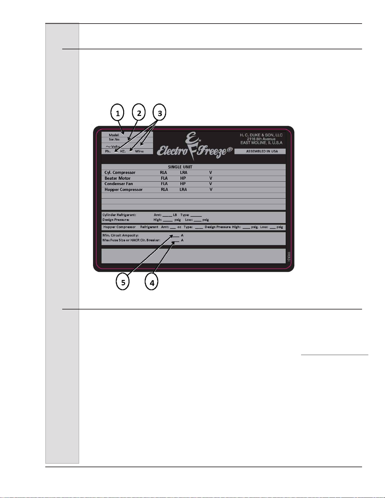
3.3 Data Plate
The data plate provides important information that the operator should record
and have available for parts ordering,
warranty and service requests.
Figure 3-1
3.4 Reference Information
Write in
Reference
Information HERE!
Fill in this information as soon as you
receive the Electro Freeze GEN-2080
Soft Serve/Shake Freezer. The item
numbers, encircled, correspond with the
call-out numbers in gure 3-1.
1.) Model Number: ________________
2.) Serial Number: ________________
3.) Electrical Spec: Voltage _________
Phase _______ Hertz _________
4.) Maximum Fuse Size: ____________
5.) Minimum Circuit Ampacity:________
185240 5
ELECTRO FREEZE Soft Serve Model GEN-2080
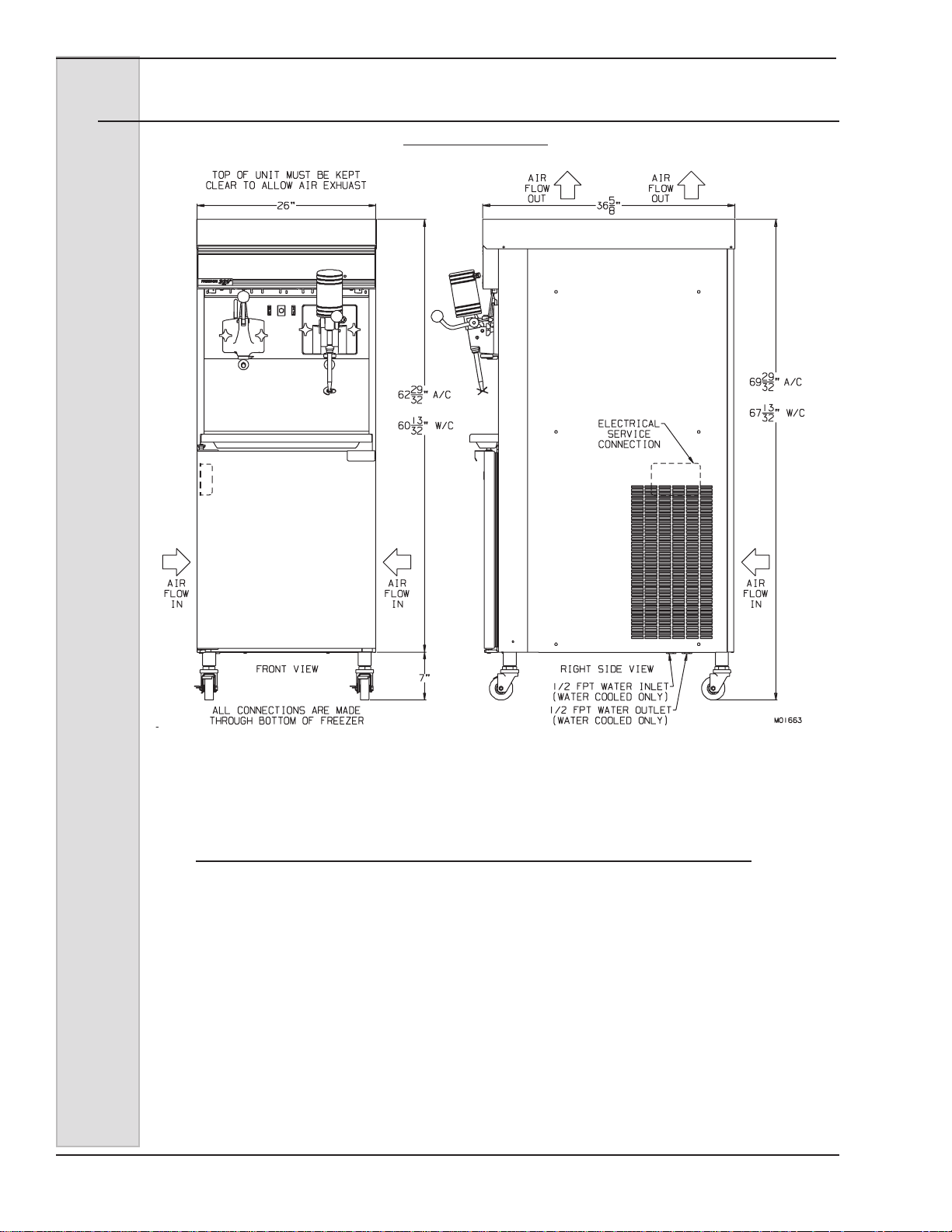
3.5 Dimensions
MODEL GEN-2080
W/C = Water Cooled Models
A/C = Air Cooled Models
ACR = Air Cooled Remote Models dimensions are the same as W/C
Figure 3-2
6 185240
ELECTRO FREEZE Soft Serve Model GEN-2080
NOTE: Combination Soft Serve/Shake
Freezers
Please note that in the following pages of this manual,
some sections relate specifically to either the “Soft
Serve” side of the freezer or the “Shake” side of the
freezer. The GEN-2080 combination freezer actually
contains two separate systems — one side provides
soft serve ice cream and the other, shakes. Although
there are some part and procedure similarities
between the shake and soft serve sides, we have
separated them to make it easier for you to find the
information you need. You may notice a duplication of
some information. Where feasible the information is
only provided once, for both sides.
Look for the Electro Freeze Cone and term “Soft
Serve” in the section header for instructions
concerning the frozen dessert side of the freezer.
Look for the Electro Freeze Shake and the term
“Shake” in the section header for instructions
concerning the shake side of the freezer.
185240 7
ELECTRO FREEZE Soft Serve Model GEN-2080
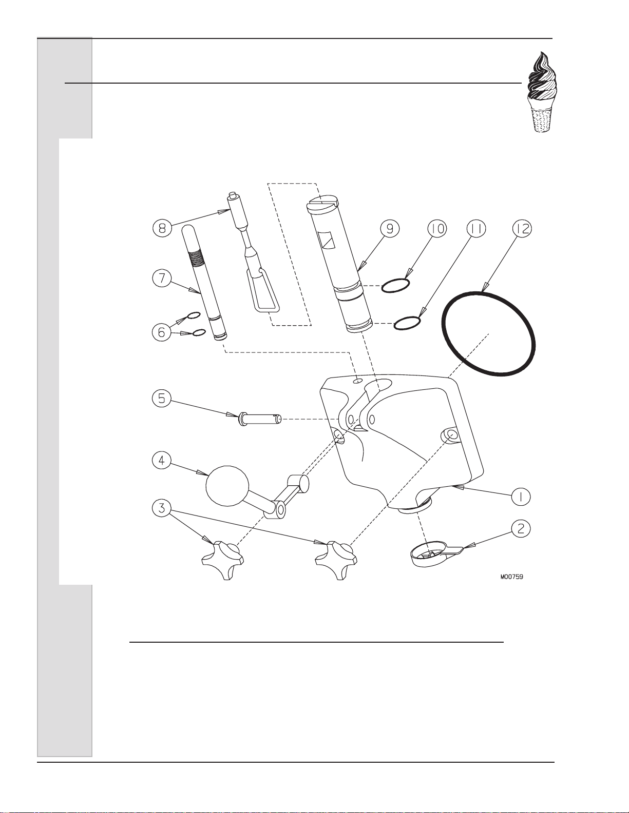
4 Part Names and Functions — Soft Serve
ROD-PLUNGER
PLUG-AIR BLEED
O-RING-PLUG
PIN-HANDLE
HANDLE-DISPENSE
KNOB-HAND
PLUNGER
O-RING-HEAD
O-RING-PLUNGER
O-RING-PLUNGER
HEADDISPENSE
Figure 4-1 Head Assembly
8 185240
NOZZLE

ELECTRO FREEZE Soft Serve Model GEN-2080
4 Part Names and Functions — Soft Serve
The following descriptions apply to gure 4-1. The number preceding the
part name corresponds to the number in the gure.
1.) HEAD: Encloses the freezing
cylinder and provides an opening for
product to be dispensed.
2.) NOZZLE: Shapes the frozen
product as it is dispensed.
3.) KNOB-HAND: Secures the
dispensing head to the freezing
cylinder.
4.) HANDLE-DISPENSE: Opens and
closes the plunger to start and stop
the ow of product from the freezer.
5.) PIN-HANDLE: Secures the handle
to the dispense head.
6.) O-RING-PLUG: Seals the air bleed
plug in the dispense head.
7.) PLUG-AIR BLEED: Seals the air
bleed opening in the head when
closed. Allows excess air to be
removed from the cylinder in the
lling process.
8.) ROD-PLUNGER: Starts the freezer
when dispensing. Must be in place
before freezer will operate.
9.) PLUNGER: Seals the product
opening in the head when closed.
Allows product to ow when open.
10.) O-RING-PLUNGER-UPPER: Seals
the plunger in the dispensing head.
Must be lubricated to seal and slide
properly.
11.) O-RING-PLUNGER-LOWER: Seals
the plunger in the dispensing head.
Must be lubricated to seal and slide
properly.
12.) O-RING-HEAD: Seals the
dispensing head to the freezing
cylinder. Must be lubricated.
185240 9

ELECTRO FREEZE Soft Serve Model GEN-2080
4 Part Names and Functions — Soft Serve
Figure 4-2 Soft Serve Beater Shaft Assembly
10 185240
ELECTRO FREEZE Soft Serve Model GEN-2080
4 Part Names and Functions — Soft Serve
The following descriptions apply to gure 4-2. The number preceding the
part name corresponds to the number in the gure.
1.) BUSHING - CYLINDER: Holds the
beater in place at the front of the cylinder. Center must be lubricated.
2.) SHAFT - ASSY. BEATER: Rotates
in the freezing cylinder, blending air
and mix as it ejects product.
3.) BLADE - SCRAPER SOFT SERVE:
Scrapes the frozen product from the
freezing cylinder wall.
Important:
Soft serve blades only have 2 holes
and are not interchangeable with the
3 hole shake blades. If the incorrect
blades are used the freezer could be
damaged.
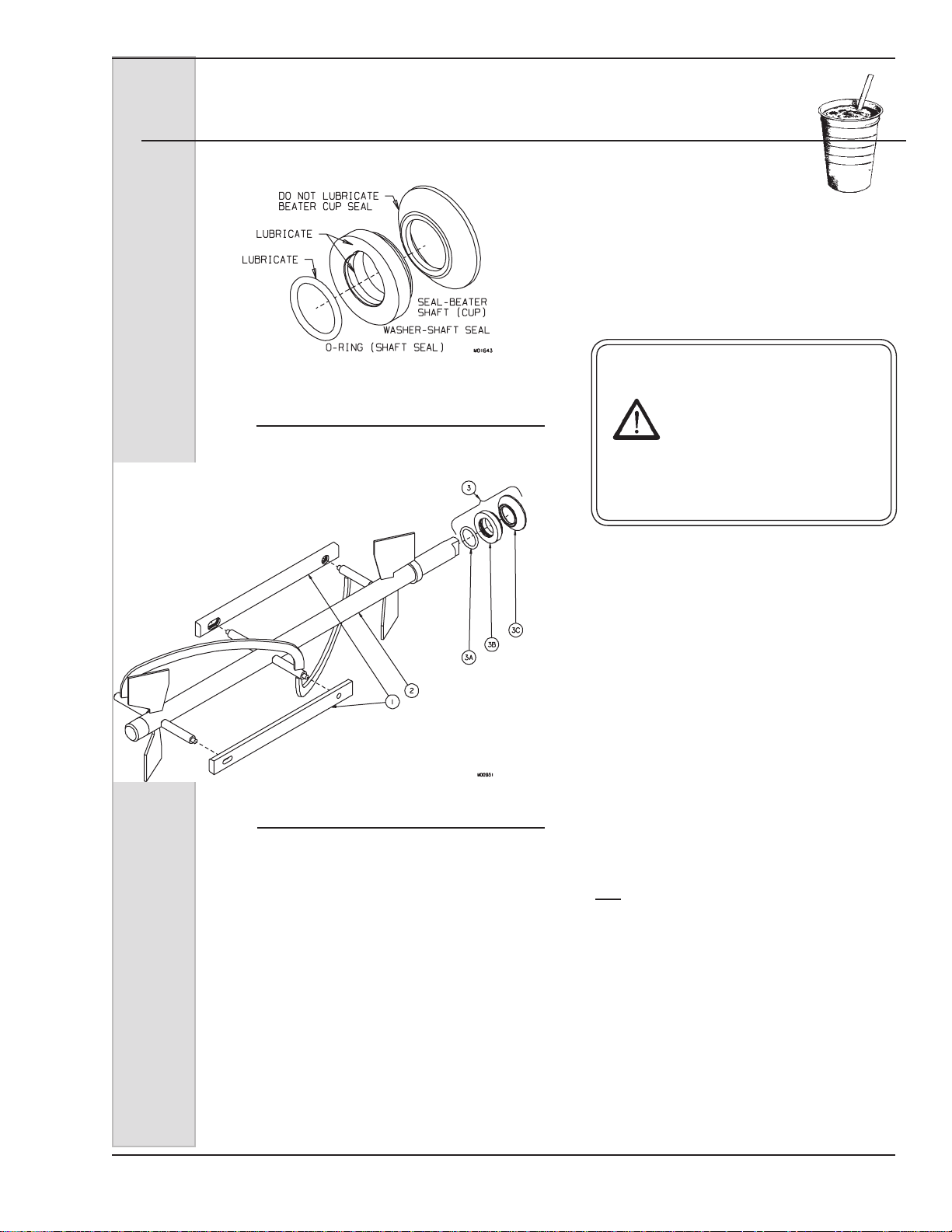
4.) O-RING - SHAFT SEAL: Seals the
beater shaft to the shaft seal. Is
inserted into the shaft seal bushing.
Must be lubricated.
5.) WASHER - SHAFT SEAL: Holds
the shaft seal o-ring. Lightly lubricate the side opposite the cup
seal.
6.) SEAL(CUP) - BEATER SHAFT:
Seals the opening between the
freezing cylinder and the beater
shaft. Do not lubricate rubber cup
portion.
185240 11

ELECTRO FREEZE Soft Serve Model GEN-2080
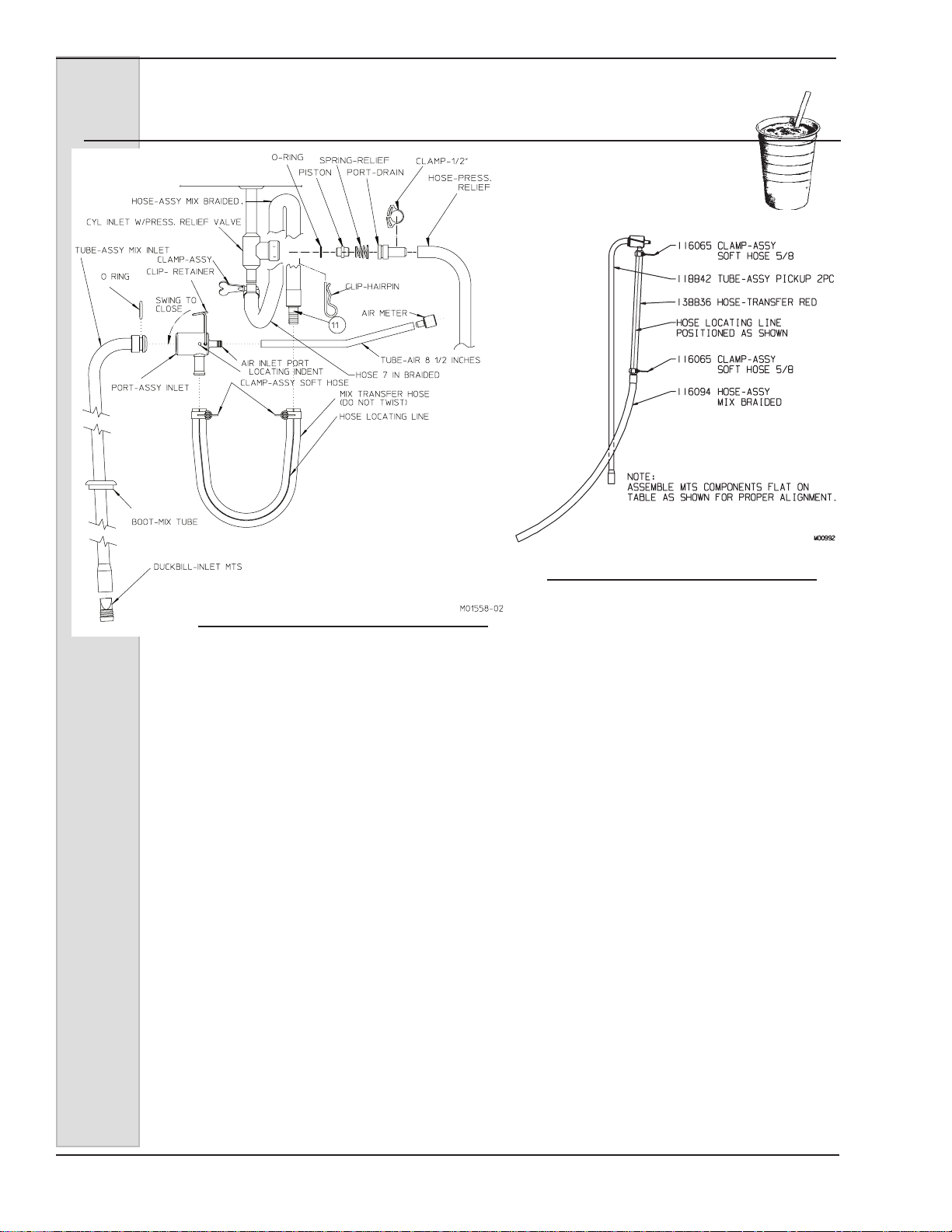
AIR METER
TUBE-AIR
RETAINER-AIR TUBE
CLAMP-SOFT HOSE
HOSE-MIX BRAIDED
SUPPORT-ROLLER
BEARING
HOSE-TRANSFER
RED LINE
ROLLER-ASSY
COMPLETE
SHOE-ROLLER
CLAMP-SOFT HOSE
O-RING
PORT-AIR/MIX INLET
CLIP-TUBE RETAINER
CLAMP-SOFT HOSE
ARM-SWING CLAMP
KNOB-HAND
COVER-MTS
TUBE-ASSY
PICKUP
DUCKBILL-INLET
20
VALVEPRESSURE RELIEF
4 Part Names and Functions
Figure 4-3 Mix Transfer System (MTS)
12 185240

ELECTRO FREEZE Soft Serve Model GEN-2080
4 Part Names and Functions
The following descriptions apply to gure 4-3. The number preceding the part
name corresponds to the number in the gure.
1.) SUPPORT-ROLLER BEARING:
Holds roller assembly in place.
2.) SHOE-ROLLER: Provides an
opening to insert the mix transfer
hose. Squeezes transfer hose
against rollers.
3.) ROLLER ASSEMBL Y COMPLETE:
Squeezes mix/air through tubing to
freezing cylinder.
4.) KNOB-HAND: Locks roller shoe in
position.
5.) CLAMP-SHOE: Swings hand knob
into position over roller shoe.
6.) RETAINER-AIR TUBE: Holds air
meter tube in the “up” position.
7.) AIR METER: Regulates the amount
of air being drawn into the system.
8.) TUBE-AIR: Provides connection for
the air meter.
12.) HOSE - TRANSFER RED: Special
“red-lined” hose that is squeezed by
rollers to transfer mix to freezer.
13.) TUBE-ASSEMBLY MIX INLET:
Carries mix from mix container to
MTS.
14.) DUCKBILL: A rubber check valve
that prevents mix from falling back
into the mix container.
15.) PORT - AIR/MIX: Blends air and
mix as it ows into the transfer
hose.
16.) CLIP - TUBE RETAINER: Locks
mix pickup tube into air/mix port.
17.) O-RING: Seals the mix tube in the
air/mix port.
9.) CLAMP - ASSY. SOFT HOSE 5/8”:
Prevents mating parts from leaking.
10.) HOSE - ASSY. MIX BRAIDED:
Connecting tube between the Mix
Transfer System and the cylinder
inlet.
11.) COVER - MTS: Protection against
moving parts. Cover must be in
place for the MTS to operate.
185240 13

ELECTRO FREEZE Soft Serve Model GEN-2080
5 Part Names and Functions — Shake
Figure 5-1 Head Assembly
14 185240

ELECTRO FREEZE Soft Serve Model GEN-2080
5 Part Names and Functions — Shake
The following descriptions apply to gure 5-1. The number preceding the
part name corresponds to the number in the gure.
1.) HEAD - ASSY. W/ACTUATOR:
Encloses the freezing cylinder and
provides an opening for product to
be dispensed.
2.) BUSHING - BEATER BEARING:
Holds the beater in place at the front
of the cylinder. Must be inserted
into the head and lubricated before
assembly.
3.) O-RING - HEAD: Seals the head
to the freezing cylinder. Must be
lubricated.
4.)
and
5.) O-RINGS - PLUNGER: (UPPER &
LOWER): Seals the plunger in the
head. Must be lubricated to seal and
slide properly.
6.) PLUNGER - DISPENSING BLACK:
Seals the product opening in the head
when closed. Allows product to ow
when open.
7.) PUSH ROD - ASSY. PLUNGER
SWITCH: Starts the freezer when
dispensing. Must be in place before
freezer will operate.
12.) O-RING - PIVOT POST:
Holds the pivot post in place.
13.) HANDLE - ASSY. SPINDLE HEAD:
Opens and closes the plunger to
start and stop the ow of product
from the freezer.
14.) KEEPER - ASSY. SPINDLE: Secures the handle to the head.
15.) KNOB - HAND: Secures the head
to the freezing cylinder.
16.) O-RING - AIR RELIEF PLUG:
Seals the air relief screw in the
head.
17.) PLUG - AIR RELIEF: Seals the
air relief opening in the head when
closed. Allows excess air to be
removed from the cylinder when
lling.
18.) EXTENSION-SHAKE SPIGOT:
Product ows from the head through
the extension.
19.) O-RING-SPIGOT EXTENSION:
Seals the extension to the head.
8.) FUSE - SLO BLOW 1A: Prevents the
spindle motor from overload.
9.) SPINDLE - ASSY. FRONT MOUNT:
Mixes the shake as it is dispensed.
10.) O-RING - SPINDLE ASSY.: Holds the
spindle in place.
11.) POST - PIVOT (Optional): Holds
the handle in place when the spindle is not used.
185240 15
ELECTRO FREEZE Soft Serve Model GEN-2080
5 Part Names and Functions — Shake
Figure 5-2
16 185240
ELECTRO FREEZE Soft Serve Model GEN-2080
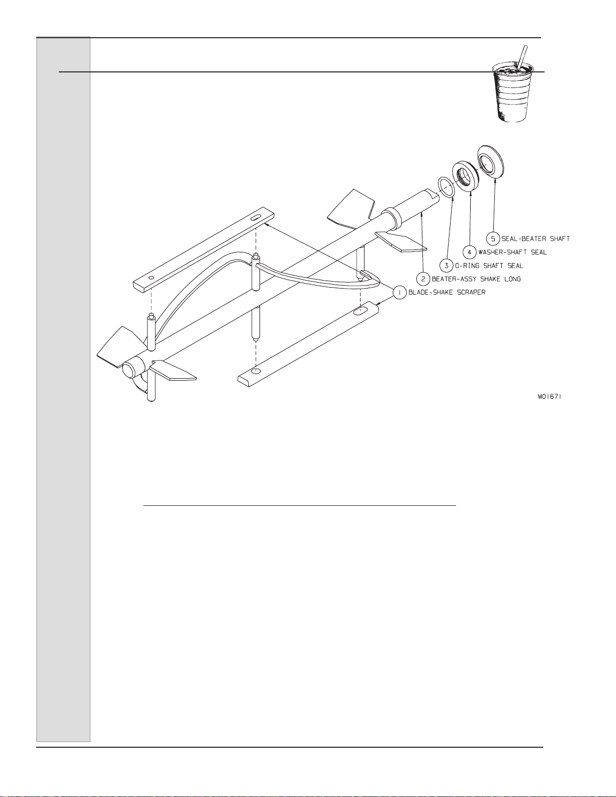
5 Part Names and Functions — Shake
The following descriptions apply to gure 5-2. The number preceding the
part name corresponds to the number in the gure.
1.) BLADE - SCRAPER: Scrapes the
frozen product from the freezing
cylinder wall.
Important:
Shake blades have 3 holes and are
not interchangeable with the 2 hole
soft serve blades. If the incorrect
blades are used the freezer could be
damaged.
2.) SHAFT - BEATER: Rotates in the
freezing cylinder, blending air and mix
and ejecting product.
3.) O-RING-SHAFT SEAL: Seals the
beater shaft to the shaft seal. Is
inserted into the shaft seal washer.
Must be lubricated.
4.) WASHER-SHAFT SEAL: Holds the
shaft seal o-ring. Lightly lubricate
the side opposite the cup seal.
5.) SEAL(CUP)-BEATER SHAFT: Seals
the opening between the freezing
cylinder and the beater shaft. Do not
lubricate rubber cup portion.
185240 17

ELECTRO FREEZE Soft Serve Model GEN-2080
L1
23
45 6789
10
2
4
L2 R1 R2
1
LEFT RIGHT
OFF
OFF
6 Operator Controls
Figure 6-1
The following paragraphs describe the
operator controls. Refer to Fig. 5-1 for
numbered items in description. Note
the left side controls operates the left
side cylinder. Operation for right side
controls is the same. The display
window has three levels of display:
Operators Menu, Technician Menu. The
last menu is restricted and reserved for
use by qualied personnel.
NOTE: The dispense head must be in
place before the freezer will operate.
CAUTION
Test operation of the head
switch prior to placing
the freezer in service.
See Section 11, Routine
Maintenance, Monthly.
1. Function Buttons (Four)
Pressing any of these buttons will activate the icon directly above in the display screen.
Left side (L1 & L2), Right Side (R1& R2).
2. OFF Key
When this symbol is pressed, the left side of unit will shut off. The beater motor and
compressor will not operate.
3. Navigation Pad (Up/Down = Cabinet ON/OFF)
Used to navigate the menu structure. Up/Down arrows are used to turn the cabinet
on/off when both cylinders are off. Used by technicians for programming and setting
changes. See Troubleshooting section for Operator accessible controls.
4. Freeze Symbol
18 185240
When this symbol is pressed, the unit will enter the automatic freeze mode. Both
the hopper and cylinder compressors will energize to refrigerate product to settings
in program. Use this button for DAY mode operation to maintain product in “ready
to serve” state.
ELECTRO FREEZE Soft Serve Model GEN-2080
6 Operator Controls (continued)
5. Left or Right side Control Indicator
Left indicates controls for left side cylinder and hopper. “Right” Indicates controls
for right side of freezer cylinder and hopper.
6. Mode of Operation Indicator
There are three primary modes of operation:
a. OFF –This is the indicator when power is applied to freezer and when
(OFF) button is pressed. In this mode, the refrigeration and beater motor
will not operate.
b. FRZ – This is the indicator when Freeze button is pressed. In this
mode, the freezer is in automatic freeze mode and both the beater motor
and refrigeration will activate as needed. Use this position for dispensing
product from freezer. Cabinet will also be refrigerated as needed to
maintain product below 41°F.
Important:
in the cylinder or hopper. The freezer will be damaged.
c. Standby – This is the indication when the Night button is pressed. In this
mode, an energy-saving feature will activate and reduce product
refrigeration. The freezer will automatically cycle to maintain temperatures
in the cylinder and cabinet below 41°F and keep product from deteriorating.
Use this position when the freezer will not be in use for periods of more
than one hour.
Important:
cleaning and sanitation procedures at the frequencies required by the
federal, state, or local regulatory agency.
Do not use the freeze position with water or sanitizer
Night/standby mode is not to be used in lieu of proper
7. Wash or Clean Mode
Press the function button directly below icon to activate clean mode. Also allows
individual activation of the mix pump & beater.
8. Information Window
This window is normally blank when unit is functioning properly. This window will
give you indication when mix in hopper is low and other error messages. Refer to
Troubleshooting Section of manual for details on error messages.
9. Standby Indicator
This is the indication when the Night button is pressed. In this mode, an energysaving feature will activate and reduce product refrigeration. The freezer will
automatically cycle to maintain temperatures in the cylinder and cabinet below 41°F and
keep product from deteriorating. Use this position when the freezer will not be in use for
periods of more than one hour.
10. Hidden Operator Menu Key
Press this key to enter the operator menu to adjust the freezers settings.
185240 19

ELECTRO FREEZE Soft Serve Model GEN-2080
LEFT RIGHT
OFF
OFF
L1
23
45 6789
10
2
4
L2 R1 R2
1
LEFT RIGHT
OFF
OFF
6 Operator Controls (continued)
11 Power Switch See Figure 6-3
In the “ON” position, power is supplied
to the beater motors. Use this position
11
to operate the freezer. Select the ”OFF”
position for disassembly and cleaning.
See Operators Display Menu for use of
this switch in recording cleaning cycles.
Figure 6-3
7 Operator Display Menus
Figure 7-1
To Enter the Operator Menu, push and hold the hidden key (11) under the F for 3 seconds
(gure 6-1).
Figure 7-2
The operator menu will show up on the screen (gure 7-2). The cursor will highlight the selected
sub-menu (i.e. Basic Setting, Actual Temps, etc.), use the Arrow Buttons to move the cursor up or
down to the desired sub-menu. Once the desired menu is highlighted, in this example we will use
Basic Settings, press the select (
Offset will be shown for left and right barrel. Use the Arrow Buttons to move the cursor to highlight
the value to be changed, once highlighted press the select button and the cursor will now be
) button to enter the sub-menu. Product Type and Temperature
blinking. While the cursor is blinking the value may now be changed using the left or right Arrow
Buttons, once you have reached the desired setting press select (
) one more time, the cursor
will now stop blinking, this indicates that the value change has been stored. Follow these steps to
change any other desired settings, once complete you may use the far right Function button to exit
the operator menu or just wait and the menu will time out and return to the Home screen.
20 185240

ELECTRO FREEZE Soft Serve Model GEN-2080
7 Operator Display Menus
Below is a list of the menu categories that are displayed upon entering the
Operator’s menu.
Operator’s Menu Options
• Basic Settings
• Actual T emps
• Event Log
• Error Log
• Lockouts
• Screen Settings
• Date/Time
• Last Clean
• Software Version
The following information explains more about each of the menu options.
Basic Settings: Information Shown
Left Barrel: nonfat, lowfat, highfat, or yogurt
Right Barrel: nonfat, lowfat, highfat, or yogurt
Temperature Offset 1-9, 5 is neutral
Actual Temps: Information Shown
Cabinet Temperature
Cylinder Temperature: Left or Right Cylinder
Event Log: Allows the operator to look at logged events i.e. power switch cycle, low
Error Log: Allows the operator to look at logged errors i.e. Barrel refrigeration
Statistics: Shows the number of starts that the compressor/compressors,
switches and beater motors have seen. Also displays the cumulative
run time in hours for compressors and beater motors.
Information Shown
On Time Left & Right Barrel
Freeze Mode Left & Right Barrel
Standby Mode Left & Right Barrel
Off Left & Right Barrel
Last PWR Fail
All PWR Fail Time
All PWR Fails
Product Type
mix, etc. The log will display the last 50 events with the newest
event at the top.
timeout, low/high refrigeration pressure, etc. The log will display the
last 50 events with the newest event at the top.
185240 21

ELECTRO FREEZE Soft Serve Model GEN-2080
7 Operator Display Menus (continued)
Spigot Left & Right Barrel
Statistics Cont.
Center Spigot
Spigot Hours Left & Right Barrel
C Spigot Hours
Comp. Starts Left & Right Barrel
Comp. Hours Left & Right Barrel
Beater Starts Left & Right Barrel
Beater Hours Left & Right Barrel
Cab Comp. Starts
Cab Comp. Hours
Pump Starts Left & Right Barrel
Pump Hours Left & Right Barrel
Lockouts: Allows the operator to lock out the clean, freeze, and night function
so that on the home screen when the button is pressed the unit will
not react.
Information Shown
Freeze Mode Y or N
Clean Mode Y or N
Standby Mode Y or N
Cab Only Mode Y or N
Cones Left 5
Screen Settings: Operator can turn on or off the following functions:
Display Cabinet Temperature Y or N
(Will or will not display Cabinet temp. on home screen)
Alternate Moon Y or N
Beep Function Y or N
(unit will or will not beep when a button is pressed)
Hide Clock Error Y or N
Date/Time: Allows user to set the Real Time Clock and current date in the unit.
Last Clean: Displays the Last time the unit has been cleaned
Software Versions: Has current software version numbers for both the U.I. and Main
board
Main ———
U.I. ————
Model GEN
Cyl Count 2
Compressors 2
Hopper Y or N
Cabinet Y or N
Product Table GEN or SLX
22 185240

ELECTRO FREEZE Soft Serve Model GEN-2080
LEFT RIGHT
OFF
OFF
Press to start Left Clean Mode
Press to start Right Clean Mode
CABINET
ON
370F
LEFT RIGHT
OFF
OFF
CABINET
ON
370F
PUMP
ON OFF
PUMP
ON OFF
BEATER
ON OFF
BEATER
ON OFF
Press to turn left
beater on
Press to turn left
pump on
Press to turn right
beater on
Press to turn right
pump on
LEFT RIGHT
ON
ON
CABINET
ON
370F
Press to enter Standby mode
7 Operator Display Menus (continued)
Cabinet Temperature Map for user adjustment. User will only see 1 through 9 but the table
below shows the differences with each number change. 6 is default setting
185240 23

ELECTRO FREEZE Soft Serve Model GEN-2080
8 Disassembly and Cleaning — Soft Serve
Safety Information
This freezer uses pressure to assure
consistent product quality. It is important
for your safety that the freezer is
depressurized slowly and completely
whenever the freezer is to be drained,
disassembled, cleaned, or serviced. The
safety instructions in this manual will
remind you when to check to make sure
the freezer is depressurized. When you
CAUTION
Make sure freezer is
depressurized before
proceeding.
see this CAUTION statement
the following steps should be taken:
It is important that the freezer
be disassembled, washed,
lubricated and sanitized before
operation.
The cleaning and sanitizing instructions
explained in this manual are required to
maintain a clean, sanitary freezer. The
freezer should be disassembled, cleaned,
reassembled, lubricated and sanitized
daily to ensure the best possible product
quality and freezer operation.
Persons assembling, cleaning or
sanitizing the freezer must rst wash
and sanitize hands and forearms with an
approved sanitizer.
1. Using the buttons L2 & R2 on the
control panel be sure both MTS pumps
are in the “OFF” position.
CAUTION
To avoid electrical shock or
contact with moving parts,
make sure the control pad
is “OFF” and that the main
power switch is “OFF”.
2. Turn the control pad “OFF” and then
turn “OFF” the main power switch.
3. Place a clean bucket under the
dispense head.
4. Slowly open the spigots, allowing
any pressurized cleaning solution or
air to escape. If there is product in
the freezer refer to Section 9, Closing
Procedures, 9.1 Draining Product.
5. Remove the spigot switch rods and
open the spigots completely.
6. Inside the refrigerated cabinet,
remove the MTS cover, loosen the shoe
clamp hand knob, swing back the shoe
clamp and swing open the roller shoe on
both mix transfer systems.
Following these steps will assure that the
system is depressurized.
24 185240

ELECTRO FREEZE Soft Serve Model GEN-2080
8.1 Cleaning Accessories — Soft Serve
The following accessories shipped with the freezer are necessary for cleaning,
sanitizing, and disassembly/assembly (Figure 8-1):
1.) HC158004 BRUSH: 4 inch diameter
with 36 inch handle used to clean
the shake cylinder.
2.) HC158019 BRUSH: 9/16 inch
diameter 30 inches long used to
clean drain tube, the mix feed tube
in the ceiling of the cabinet and the
pickup tube.
3.) HC158018 BRUSH: 7/16 inch
diameter 12 inches long used to
clean transfer hose, braided hose,
and the air relief opening in the
dispense head.
4.) HC158026 BRUSH: 1 inch diameter
12 inches long used to clean
the disassembled shaft seal and
bushing.
5.) HC158037 BRUSH: 1/4 inch
diameter 18-1/2 inches overall
length used to clean the air meter
hose, the small hole in the back
of the dispense head and small
parts.
6.) HC169374 TOOL - O-RING
REMOVAL: Aids in removing O-rings
from plunger, head, air relief plug,
and spindle.
7.) HC158000A LUBRICANT -
PETROL-GEL: Approved lubricant
for moving parts and O-rings.
8.) HC196103 BOTTLE, WASH:
Used to ush the hose cavity, roller
assembly and plunger.
9.) HC115530 KIT - O-RING: Contains
all O-rings and seals needing
replacement on a regular basis. (not
shown)
1
2
3
4
5
6
7
8
Figure 8-1 Cleaning Accessories
185240 25

ELECTRO FREEZE Soft Serve Model GEN-2080
8.2 Disassembly Instructions — Soft Serve
ROD-PLUNGER
PLUG-AIR BLEED
O-RING-PLUG
PIN-HANDLE
HANDLE-DISPENSE
KNOB-HAND
PLUNGER
O-RING-HEAD
O-RING-PLUNGER
O-RING-PLUNGER
HEADDISPENSE
Figure 8-2 Disassemble the Head Assembly
26 185240
NOZZLE

ELECTRO FREEZE Soft Serve Model GEN-2080
8.2 Disassembly Instructions — Soft Serve (continued)
CAUTION
Make sure freezer is
depressurized before
proceeding.
CAUTION
To avoid electrical shock or
contact with moving parts,
make sure all switches are
in the “OFF” position and
that the main power source
is disconnected. Some
freezers have more than one
disconnect switch.
1. If there is product in the freezer
refer to Section 14, Closing Procedures,
14.2 Draining Product.
2. Remove the plunger rod (8, gure
8-2) by lifting up and swinging the bottom
out and down. Remove the hand knobs
(3) and pull dispensing head (1) straight
out by gently rocking the head from the
studs.
3. Remove the cylinder bushing and
beater shaft from the cylinder.
4. Remove the scraper blades and
shaft seal (gure 8-4) from the beater
shaft.
CAUTION
To prevent bacteria
growth, remove
ALL O-rings when
disassembling for
cleaning. Failure to do
so could create a health
hazard.
5. Remove drip tray and insert from
the front of the freezer. (see Replacement
Parts Manual, Panel Assembly)
6. From the front of the head remove
the air bleed plug (7, gure 8-2) and the
two plug O-rings (6).
7. Remove the handle pin (5),
handle (4), plunger (9) and nozzle (2)
from dispensing head.
8. Remove one O-ring (12) from the
head and two O-rings (10, 11) from the
plunger.
9. Remove the cup seal (gure 8-4)
and O-ring from the bushing on the shaft
seal assembly.
10. Remove mix container, cover and
low mix probe from the cabinet.
-continued
Figure 8-3 Disassemble Beater Shaft
CUP SEAL
WASHER
O-RING
Figure 8-4 Disassemble Shaft Seal
185240 27

ELECTRO FREEZE Soft Serve Model GEN-2080
8.2 Disassembly Instructions — Soft Serve (continued)
11. Remove MTS hose assemblies
from the Mix Transfer Systems as
follows (gure 8-5):
a. remove cover,
b. loosen the hand knob,
c. swing back the shoe clamp,
d. swing open the roller shoe,
e. loosen the clamp on braided
hose,
f. pull tube off cylinder inlet and
slide hose assembly out of
roller support housing.
12. Disassemble the MTS hose
assembly as shown in gure 8-6.
Figure 8-6 MTS Hose Assembly
Figure 8-5 MTS
28 185240
ELECTRO FREEZE Soft Serve Model GEN-2080
8.3 Cleaning Instructions — Soft Serve
The cleaning instructions explained in this section are procedures to
remove bacteria and maintain a clean, sanitary freezer. The freezer must
be disassembled, washed, and sanitized according to the instructions in
this manual. Always sanitize before start-up to ensure the best possible
cleanliness.
CAUTION
To prevent bacteria growth,
remove all O-rings when
cleaning. Failure to do
so could create a health
hazard.
CAUTION
Electrical shock hazard.
Do not splash water on
switches or allow water
to ow onto electrical
components inside the
machine.
NOTE: It is your responsibility to
be aware of and conform to the
requirements for meeting federal, state
and local laws concerning the frequency
of cleaning and sanitizing the freezer.
1. Prepare a three-compartment
sink for washing, rinsing, and sanitizing
parts removed from the freezer, per
applicable local health codes. Also,
prepare a clean surface to air-dry all
parts.
a. The mix container, pickup tube
assembly, hoses and probe.
b. The head plunger openings,
plunger ports, O-ring grooves, dispense
nozzle mounting rings and mix ports as
shown in gure 8-7.
Figure 8-7 Clean head ports and
openings with brush.
c. The beater shaft cup seal,
plastic washer, and O-rings, plunger
O-ring grooves and nozzle, as shown in
gure 8-8.
Important:
Do not use unapproved sanitizer
or laundry bleach. These materials
may contain high concentrations of
chlorine and will chemically attack
freezer components.
NOTE: The sanitizer should be
mixed according to the manufacturer’s
instructions to yield 100 PPM strength
chlorine solution (example: Stera Sheen
Green Label). Use warm water (100° to
110°F or 38° to 43°C) to wash, rinse, and
sanitize.
2. Wash all parts removed from the
Figure 8-8 Clean O-ring grooves,
seal and nozzle with
brush.
freezer thoroughly with dish detergent.
Clean the following parts with the
— continued
appropriate supplied brush:
185240 29

ELECTRO FREEZE Soft Serve Model GEN-2080
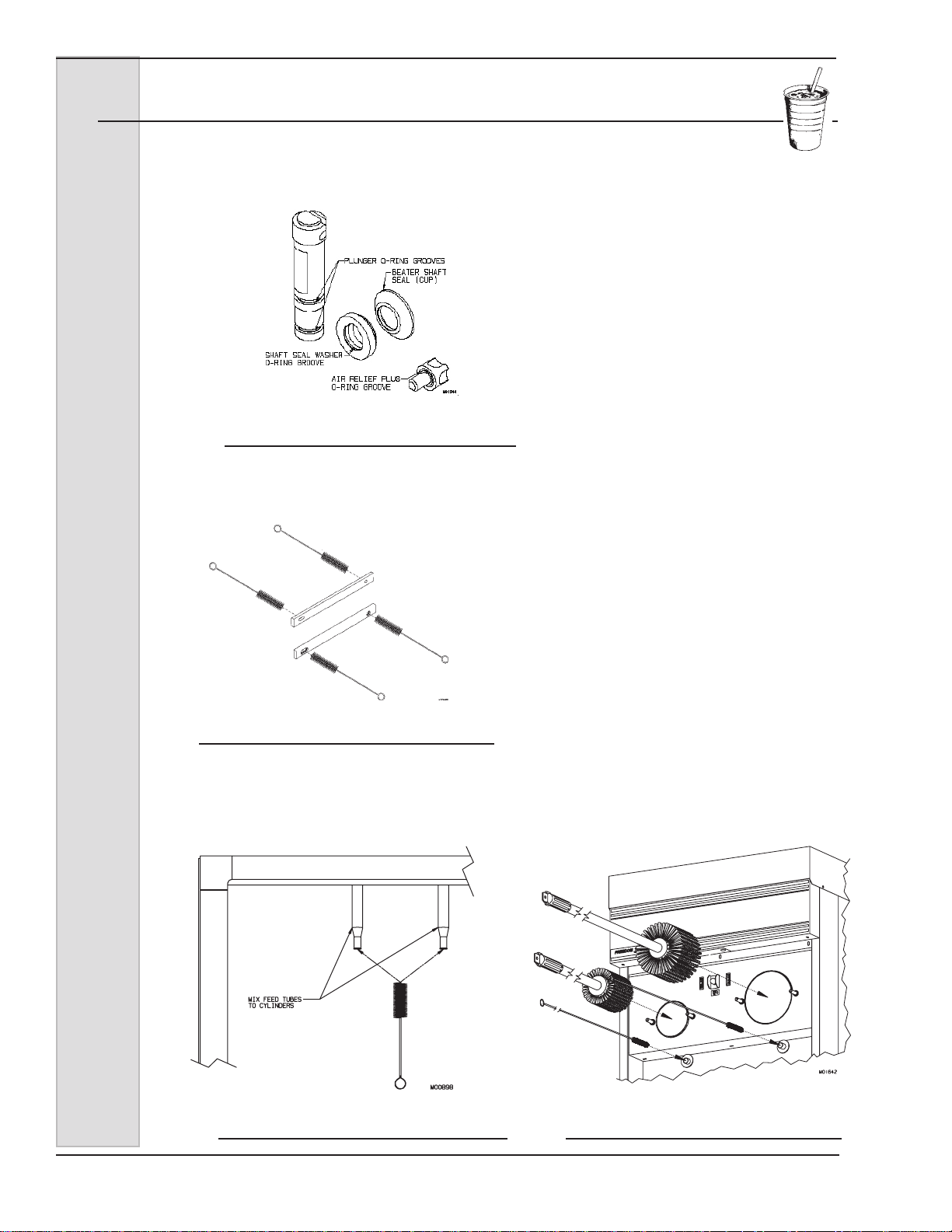
8.3 Cleaning Instructions — Soft Serve (continued)
d. The air bleed plug O-ring
grooves.
e. The beater shaft and the
Figure 8-9 Clean Scraper Blade Pin Holes
scraper blade pin holes as shown in gure
8-9.
3. After all parts are washed, rinse
and then place them in the sanitizing
solution. For proper sanitizing, the
parts must remain fully immersed in the
sanitizer for 5 minutes. Allow parts to airdry after sanitizing.
Do not leave parts in sanitizing
solution for more than 15 minutes.
Important:
Figure 8-10 Brush inside of cylinder mix
feed tubes.
3. After all parts are washed, rinse
and place in the sanitizing solution.
Brush the inside of all mix transfer hoses
with sanitizer. For proper sanitizing, the
parts must remain fully immersed in the
sanitizer for 5 minutes. Allow parts to airdry after sanitizing.
4. Using a warm mild dish detergent
solution thoroughly brush:
a. the mix feed tubes from the
cabinet to the cylinders (gure 8-10)
b. the inside of the cylinders
making certain to clean the back walls,
and the inside of the drain tube as shown
in gure 8-11 (dip the brush in the dish
detergent solution and force into the drain
tube until it stops - repeat until clean).
5. Wash the drip tray and insert in
the warm dish detergent solution and
rinse with clear water.
6. Wash the outside of the freezer
and the inside of the cabinet with the dish
detergent solution. Rinse with clear water.
Figure 8-11 Brush inside of cylinders and
drain tubes.
30 185240
ELECTRO FREEZE Soft Serve Model GEN-2080
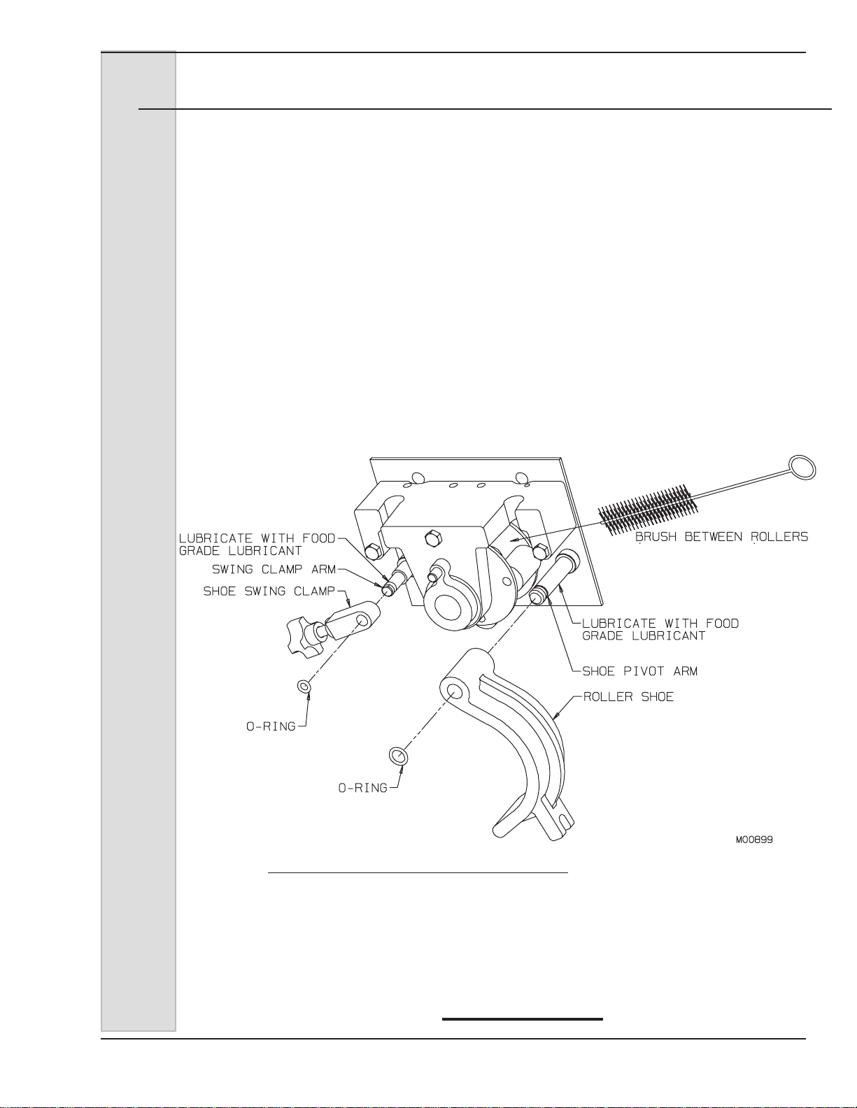
8.3.1 Cleaning and Lubricating MTS Assembly Shoe
NOTE: Clean the shoe weekly or when
necessary. Do not interchange the shoe
with any other MTS shoes.
Follow these directions for each MTS
shoe:
1. Remove the O-rings and slide the
shoe off of the pivot arm and the swing
clamp off of the clamp arm. See gure
7-12.
2. Carry to the sink, wash in mild
detergent with the brush provided and dry
thoroughly.
3. Brush in between rollers. Flush
clean with water bottle.
Important:
Do not let shoe sit in sanitizing
solution or water. Corrosion will occur
in bore.
4. Lubricate the shoe pivot arm and
the swing clamp arm with food grade
lubricant such as Petrol-Gel.
5. Reassemble the shoe and O-ring
on pivot arm.
6. Reassemble the shoe swing
clamp and O-ring on the swing clamp
arm.
Figure 8-12
Replace worn brushes. Use only Electro Freeze original
or authorized replacement parts. See Accessories parts
list in Part II of this Manual to order new brushes.
185240 31

ELECTRO FREEZE Soft Serve Model GEN-2080
9 Disassembly and Cleaning — Shake
Safety Information
This freezer uses pressure to assure
consistent product quality. It is important
for your safety that the freezer is
depressurized slowly and completely
whenever the freezer is to be drained,
disassembled, cleaned, or serviced. The
safety instructions in this manual will
remind you when to check to make sure
the freezer is depressurized. When you
CAUTION
Make sure freezer is
depressurized before
proceeding.
see this CAUTION statement
the following steps should be taken:
It is important that the freezer
be disassembled, washed,
lubricated and sanitized before
operation.
The cleaning and sanitizing instructions
explained in this manual are required to
maintain a clean, sanitary freezer. The
freezer should be disassembled, cleaned,
reassembled, lubricated and sanitized
daily to ensure the best possible product
quality and freezer operation.
Persons assembling, cleaning or
sanitizing the freezer must rst wash
and sanitize hands and forearms with an
approved sanitizer.
1. Using the buttons L2 & R2 on the
control panel be sure both MTS pumps
are in the “OFF” position.
CAUTION
To avoid electrical shock or
contact with moving parts,
make sure the control pad
is “OFF” and that the main
power switch is “OFF”.
2. Turn the control pad “OFF” and then
turn “OFF” the main power switch.
3. Place a clean bucket under the
dispense head.
4. Slowly open the spigots, allowing
any pressurized cleaning solution or
air to escape. If there is product in
the freezer refer to Section 9, Closing
Procedures, 9.1 Draining Product.
5. Remove the spigot switch rods and
open the spigots completely.
6. Inside the refrigerated cabinet,
remove the MTS cover, loosen the shoe
clamp hand knob, swing back the shoe
clamp and swing open the roller shoe on
both mix transfer systems.
Following these steps will assure that the
system is depressurized.
32 185240
ELECTRO FREEZE Soft Serve Model GEN-2080
9.1 Cleaning Accessories — Shake
The following accessories shipped with the freezer are necessary for cleaning,
sanitizing, and disassembly/assembly (Figure 9-1):
1.) HC158005 BRUSH: 6 inch diameter
with 36 inch handle used to clean the
shake cylinder.
2.) HC158019 BRUSH: 9/16 inch
diameter 30 inches long used to clean
drain tube, the mix feed tube in the
ceiling of the cabinet and the pickup
tube.
3.) HC158037 BRUSH: 1/4 inch diameter
18-1/2 inches overall length used to
clean the air meter hose, the small
hole in the back of the dispense head
and small parts.
4.) HC158018 BRUSH: 7/16 inch
diameter 12 inches long used to clean
transfer hose, braided hose, and the
air relief opening in the dispense
head.
5.) HC158026 BRUSH: 1 inch diameter
12 inches long used to clean the
disassembled shaft seal and bushing.
6.) HC169374 TOOL - O-RING
REMOVAL: Aids in removing O-rings
from plunger, head, air relief plug, and
spindle.
7.) HC158000A: LUBRICANT PETROL-GEL. Approved lubricant
for moving parts and O-rings.
8.) HC116588 KIT - O-RING: Contains
all O-rings and seals needing
replacement on a regular basis.
(not shown)
1
2
3
6
4
5
7
Figure 9-1 Cleaning Accessories
185240 33

ELECTRO FREEZE Soft Serve Model GEN-2080
9.2 Disassembly Instructions— Shake
Figure 9-2 Shake Head Assembly
34 185240

ELECTRO FREEZE Soft Serve Model GEN-2080
9.2 Disassembly Instructions — Shake (continued)
SEAL-ASSY. SHAFT
1. If there is product in the freezer
refer to Section 14 Closing Procedures,
14.2 Draining Product.
2. Refer to gure 9-2. Remove the
plunger rod (7) by lifting up and swinging
CUP SEAL
WASHER
O-RING
BEATER-ASSY. SHAKE LONG
BLADE-SCRAPER
Figure 9-3 Beater Shaft Assembly
the bottom out and down.
3. Pull the keeper (11) out of the
head (1).
4. Unplug the spindle motor (8) and
lift it upward, removing it from the head.
5. Remove the handle (10) and
hand knobs (15), and then pull the head
straight out by gently rocking the head
from the studs.
CUP SEAL
WASHER
O-RING
Figure 9-4 Shaft Seal Assembly
CAUTION
Make sure freezer is
depressurized before
proceeding.
CAUTION
To avoid electrical shock or
contact with moving parts,
make sure all switches are
in the “OFF” position and
that the main power supply
is disconnected. Some
freezers have more than one
disconnect switch.
6. Remove the head bushing (2) and
the beater shaft from the cylinder.
7. Remove the scraper blades and
shaft seal from the beater shaft. Refer to
gure 9-3)
CAUTION
To prevent bacteria growth,
remove all O-rings when
cleaning. Failure to do so
could create a health hazard.
8. If you haven’t already removed
the drip tray (See Replacements Parts
Manual, Panel Assembly) and drip tray
insert from the front of the freezer, do so
now.
9. From the head remove the
plunger (6), and O-rings (4 & 5) from the
plunger.
10. Unscrew the air relief plug (13)
and o-ring (14), and head o-ring (3) from
the head.
11. Refer to gure 9-4. Remove
the cup seal and O-ring from the plastic
washer on the beater shaft seal assembly.
12. Remove mix tank, covers, and low
mix probe from inside the cabinet.
— continued
185240 35

ELECTRO FREEZE Soft Serve Model GEN-2080
9.2 Disassembly Instructions — Shake (continued)
13. Remove MTS hose assembly
from the Mix Transfer System as follows
(gure 9-5):
a. remove cover,
b. loosen the hand knob,
c. swing back the shoe clamp,
d. swing open the roller shoe,
e. loosen the clamp on braided
hose,
f. pull the braided hose off the
cylinder inlet and slide the mix transfer
hose assembly out of the roller support
housing.
14. Disassemble the MTS
hose assembly as shown in
gure 9-6.
Figure 9-5 MTS
Figure 9-6 MTS Hose Assembly
36 185240

ELECTRO FREEZE Soft Serve Model GEN-2080
9.3 Cleaning Instructions — Shake
The cleaning instructions explained in this section are procedures to remove
bacteria and maintain a clean, sanitary freezer. The shake freezer must be
disassembled, washed and sanitized according to the instructions in this
manual before start-up to ensure the best possible cleanliness.
CAUTION
Electric shock hazard.
Do not splash water on
switches or allow water
to ow onto electrical
components inside the
machine.
CAUTION
To prevent bacteria growth,
remove ALL O-rings when
cleaning. Failure to do
so could create a health
hazard.
Important:
Do not use unapproved sanitizers
or laundry bleach. These materials
may contain high concentrations of
chlorine and will chemically attack
freezer components.
NOTE: It is your responsibility to
be aware of, and conform to, the
requirements for meeting federal, state,
and local laws concerning the frequency
of cleaning and sanitizing the freezer.
1. Prepare a three-compartment sink
for cleaning, rinsing, and sanitizing parts
removed from the freezer, per applicable
health codes. Also, prepare a clean
surface to air-dry all parts.
NOTE: The sanitizer should be mixed
according to the manufacturer’s
instructions to yield 100 PPM strength
chlorine solution (example: Stera Sheen
Green Label). Make sure that sanitizer
has completely dissolved and/or is mixed
thoroughly. Use warm water (100° to
110°F or 38° to 43°C) to wash, rinse, and
sanitize.
Important:
Do not submerge the spindle motor in
water. This will damage the motor.
2. Wash all parts removed from the
freezer thoroughly with dish detergent
soap. Clean the following parts with the
appropriate supplied brush:
a. the mix tank, pickup tube
assembly, hoses and probe
b. the head, plunger, spindle, and
air relief plug openings, and all O-ring
grooves, as shown in gure 9-7.
— continued
Figure 9-7 Clean Head Openings
and Ports
185240 37
ELECTRO FREEZE Soft Serve Model GEN-2080
8.3 Cleaning Instructions — Shake (continued)
c. the shaft cup seal, plastic
washer, plunger O-ring grooves, as
shown in gure 9-8.
Figure 9-8 Clean Shaft Seal and
Plunger O-ring Grooves
d. the beater shaft and the
scraper blade pin holes, as shown in
gure 9-9.
with sanitizer. For proper
sanitizing the parts must remain fully
immersed in the sanitizer for 5 minutes.
Allow parts to air-dry after sanitizing.
4. Using a warm mild dish detergent
solution thoroughly brush:
a. the mix feed tubes from the
cabinet to the cylinders (gure 9-10)
b. the inside of the cylinders
making certain to clean the back walls,
and the inside of the drain tubes, as
shown in gure 9-11. Dip the brush in
the dish washing solution and force into
the drain tube until it stops - repeat until
clean.
5. Wash the drip tray and insert in
the warm dish detergent solution and
rinse with clear water.
6. Wash the outside of the freezer
and the inside of the cabinet with the
dish detergent solution. Rinse with clear
water.
Figure 9-9 Scraper Blade Pin Holes
3. After all parts are washed, rinse
and then place in the sanitizing solution.
Brush the inside of all mix transfer hoses
Figure 9-10 Brush inside of cylinder
mix feed tubes.
Figure 9-11 Brush the inside of the
Cylinders and Drain Tubes
38 185240

ELECTRO FREEZE Soft Serve Model GEN-2080
9.3.1 Cleaning and Lubricating MTS Assembly Shoe
NOTE: Clean the shoe weekly or when
necessary. Do not interchange the shoe
with any other MTS shoes.
Follow these directions for each MTS
shoe:
1. Remove the O-rings and slide the
shoe off of the pivot arm and the swing
clamp off of the clamp arm. See gure
8-10.
2. Carry to the sink, wash in mild
detergent with the brush provided and dry
thoroughly.
3. Brush in between rollers. Flush
clean with water bottle.
Important:
Do not let shoe sit in sanitizing
solution or water. Corrosion will occur
in bore.
4. Lubricate the shoe pivot arm and
the swing clamp arm with food grade
lubricant such as Petrol-Gel.
5. Reassemble the shoe and O-ring
on pivot arm.
6. Reassemble the shoe swing
clamp and O-ring on the swing clamp
arm.
Figure 9-10
Replace worn brushes. Use only Electro Freeze original
or authorized replacement parts. See Accessories parts
list in Part II of this Manual to order new brushes.
185240 39

ELECTRO FREEZE Soft Serve Model GEN-2080
10 Assembly — Soft Serve
Correct assembly of the freezer
is essential to prevent leakage of
the product and damage to the
freezer. To assemble the freezer
you will need an approved lubricant (such
as Petrol-Gel). Make sure all parts of
the assemblies have been washed and
sanitized before assembling.
Figure 10-1 Shaft Seal Assembly
Figure 10-2 Beater Shaft Assembly
CAUTION
To avoid electrical shock or
contact with moving parts,
make sure all switches
are in the “OFF” position
and that the main power supply is
disconnected. Some freezers have
more than one disconnect switch.
1. Persons assembling the freezer
must rst wash and sanitize their hands
and forearms with an approved sanitizer.
2. To assemble the shaft seal, install
the cup seal and O-ring on the bushing
(see gure 10-1). Apply a moderate
amount of approved sanitary lubricant
(such as Petrol-Gel) to the O-ring and the
face of the plastic bushing opposite the
bell portion of the seal. Do not allow any
lubricant to come into contact with the
bell-shaped rubber portion of the seal.
3. Install the shaft seal over the rear
of the beater shaft, with the bell-shaped
portion facing the rear, as shown in gure
10-2. Remove any excess lubricant from
the beater shaft.
PROPER BLADE
INSTALLATION
IS WITH
FLAT SIDE
AGAINST
CYLINDER WALL.
Soft serve blades only have 2 holes
and are not interchangeable with the
3 hole shake blades. If the incorrect
blades are used the freezer could be
damaged.
Important:
4. Place the scraper blades on the
beater shaft, making sure the blades are
installed properly. (see gure 10-3)
Figure 10-3 Proper blade installation
— continued
40 185240

ELECTRO FREEZE Soft Serve Model GEN-2080
10 Assembly — Soft Serve
ROD-PLUNGER
PLUG-AIR BLEED
O-RING-PLUG
PIN-HANDLE
HANDLE-DISPENSE
KNOB-HAND
Figure 10-4 Soft Serve Head Assembly
5. Insert the assembled beater shaft
into the cylinder by placing the rear blade
on the bottom of the cylinder. This will
center the beater and allow alignment
with the drive coupling. Rotate the beater
assembly while pushing, until the shank
has engaged the drive shaft.
6. Lubricate the inside surface of the
head bushing and place on the end of the
beater shaft assembly by lifting the shaft
up until the bushing slides in place.
Important:
ALWAYS make sure the head bushing
is positioned on the beater shaft
properly. Operating the freezer with
a missing or badly worn bushing
will damage the beater, head and
cylinder.
7. Refer to gure 10-4 and O-ring
Chart in the Replacement Parts Section
of this manual. Install and lubricate the
O-rings (10,11) on the dispensing plunger
(9) and insert halfway into the head (1).
8. Install and lightly lubricate the
4-inch head O-ring (12).
PLUNGER
O-RING-PLUNGER
O-RING-PLUNGER
O-RING-HEAD
HEADDISPENSE
NOZZLE
9. Position the handle (4) in the head
and plunger assembly. Lock in place with
the handle pin (5).
10. Install and then lubricate O-rings
(6) on the air bleed plug (7). Insert plug in
head (1) assembly.
11. Install the dispensing head onto
the freezer by aligning the studs with the
holes in the head and sliding toward the
freezer. Tighten the hand knobs evenly,
nger-tight only.
Important:
Excessive force will damage the head.
Do not use tools to tighten.
12. Install the plunger rod (9). The
nozzle (2) will be installed on the mix
outlet at the bottom of the head after
sanitizing.
Important:
Always inspect the mix transfer hose
during assembly for wear. Do not
use tools or sharp objects to remove
hose.
185240 41

ELECTRO FREEZE Soft Serve Model GEN-2080
10 Assembly — Soft Serve (continued)
Figure 10-5 MTS Hose Assembly
Important:
Use original Electro Freeze transfer
hose only. Your freezer will not operate
properly with any other type of hose.
Never twist the transfer hose when
assembling or installing.
Important:
Replace transfer hose every 30 days.
13. Assemble the MTS hose
assembly as shown in gures 10-5 and
9-6. The transfer hose has a red locating
line. Hold the mix/air inlet port with the
transfer hose mix port on your right and
the barbed air port facing away from you.
With the locating line up, slide the mix
transfer hose onto the port aligning it with
the small locating indent. Then slide a
clamp over the hose to secure it to the
port. Finger tighten only! The thumbscrew
must lie parallel to the mix/air inlet port.
Figure 10-6 Attaching Braided Hose
clamp. Finger tighten only! The thumb
screw must lay horizontal as shown in
gure 10-6.
15. Slide the air tube over the air inlet
port and insert air meter in the opposite
end of the air tube.
16. Install o-ring on mix inlet tube
assembly and lubricate. Place the tube
assembly end into the port assembly
and swing retainer clip over to lock tube
assembly in place.
17. Install mix tube boot with at side
rst, over the tube assembly.
18. Insert the duckbill valve into the
bottom of the pickup tube. Push until the
two ribs are completely inserted.
— continued
14. Slide another clamp over the mix
transfer hose and connect to the barbed
end of the braided hose. Tighten the
42 185240

ELECTRO FREEZE Soft Serve Model GEN-2080
10 Assembly — Soft Serve (continued)
Figure 10-7 MTS
19. Refer to gure 10-7. Install the
MTS hose assembly by rst placing the
clamp next to the braided hose, above
the roller bearing support on the right side
and push hose into slot. Place the transfer
hose under the rollers. While holding the
pickup tube stretch the hose so the left
hand clamp is above the roller bearing
support and push the hose into the slot.
Important:
Do not twist the hose assembly while
installing.
20. Check to ensure the transfer
hose is straight and centered on the
roller assembly making sure the locating
line is facing out. The line should be in
the same position at the inlet and outlet
guides of the roller bearing support, as
shown in gure 10-7.
21. Swing the shoe over hose and
tighten the swing clamp hand knob in
place until it bottoms out and will not turn
any further.
22. Insert the air tube into the
retainer in the back of the cabinet.
23. Insert the MTS cover over stud
see gure 10-8. Hose clamps should
be exposed. Tighten cover knob. Hand
tighten only.
Important:
The MTS will not operate unless the
cover is installed and secured by the
hand knob.
24. Loop the braided hose towards
you and slide the hose over the cylinder
inlet tube. Tighten the clamp. Make sure
the braided hose is not twisting transfer
hose.
— continued
185240 43

ELECTRO FREEZE Soft Serve Model GEN-2080
10 Assembly — Soft Serve (continued)
CLAMP-SOFT HOSE
O-RING
PORT-AIR/MIX INLET
CLIP-TUBE RETAINER
AIR METER
TUBE-AIR
RETAINER-AIR TUBE
CLAMP-SOFT HOSE
CLAMP-SOFT HOSE
ARM-SWING CLAMP
KNOB-HAND
COVER-MTS
TUBE-ASSY
PICKUP
HOSE-MIX BRAIDED
SUPPORT-ROLLER
BEARING
HOSE-TRANSFER
RED LINE
ROLLER-ASSY
COMPLETE
SHOE-ROLLER
20
VALVEPRESSURE RELIEF
DUCKBILL-INLET
Figure 10-8 MTS and Mix Container
44 185240
ELECTRO FREEZE Soft Serve Model GEN-2080
SEAL-ASSY. SHAFT
L
11 Assembly — Shake
Figure 11-1 Shaft Seal Assembly
Correct assembly of the
freezer is essential to prevent
leakage of the product and damage to
the freezer. To assemble the freezer you
will need an approved lubricant (such
as Petrol-Gel). Make sure all parts of
the assemblies have been washed and
sanitized before assembling.
CAUTION
To avoid electrical shock or
contact with moving parts,
make sure all switches are
in the “OFF” position and
that the main power supply
is disconnected. Some
freezers have more than
one disconnect switch.
O-RING
BEATER-ASSY. SHAKE LONG
BLADE-SCRAPER
Figure 11-2 Beater Shaft Assembly
CUP SEA
WASHER
1. Persons assembling the freezer
must rst wash and sanitize their hands
and forearms with an approved sanitizer.
2. See gure 11-1. To assemble
the shaft seal, install the cup seal and
O-ring on the bushing. Apply a moderate
amount of approved sanitary lubricant
such as Petrol-Gel to the O-ring and the
face of the plastic bushing opposite the
bell portion of the seal. Do not allow any
lubricant to come into contact with the
bell-shaped rubber portion of the seal.
3. See gure 11-2. Install the shaft
seal over the rear of the beater shaft with
the bell-shaped portion facing the rear.
Important:
Shake blades have 3 holes and are
not interchangeable with the 2 hole
soft serve blades. If the incorrect
blades are used the freezer could be
damaged.
4. Place the scraper blades on the
beater shaft, making sure the blades are
installed properly.
— continued
185240 45

ELECTRO FREEZE Soft Serve Model GEN-2080
11 Assembly — Shake (continued)
5. Insert the assembled beater shaft
into the cylinder by placing one blade
on the bottom of the cylinder and gently
pushing. This will center the beater and
allow alignment with the drive shaft.
Rotate the beater assembly
while pushing, until the
shank has engaged the drive
shaft.
Figure 11-3 Shake Head Assembly
46 185240

ELECTRO FREEZE Soft Serve Model GEN-2080
11 Assembly — Shake (continued)
Figure 11-4 Head Bushing
6. See gure 11-3 and O-ring chart
in Replacement Parts section of this
manual. Install and lubricate the O-rings
on the dispensing plunger (6) and insert
into the dispense head (1), with the slot
facing the rear of the head.
7. Install and lubricate the 6-inch
O-ring (3) on the head.
8. Install and lubricate O-ring (14) on
the air relief plug (13). Then, thread the
plug into the head assembly.
9. Lubricate the inside surface of the
head bushing (2) and place in the head
assembly, making sure to line the bushing
key into the head slot, as shown in gure
10-4.
Important:
ALWAYS make sure the head bushing
is positioned in the head properly (see
gure 11-4). The head is slotted to
match the key on the bushing. Make
sure the key aligns with the slot.
Failure to install the bushing properly
in the dispensing head will damage the
beater, head and cylinder.
10. Install the dispensing head onto
the freezer by tilting the top of the head
towards you, aligning the studs with the
holes in the head, and sliding toward
the freezer. Push the head towards the
freezer, carefully rocking it into place and
aligning the beater shaft with the drive
coupling.
11. Tighten the hand knobs
simultaneously, nger-tight only.
Important:
Excessive force will damage the head.
Do not use tools to tighten.
12. Hook the handle (10) into the
slot on the plunger (6). Insert the spindle
motor (8) into the head.
13. Insert the keeper (11) through the
holes in the handle (10), spindle (8) and
head (1). Install the spigot o-ring (17) on
the head assembly and then the spigot
extension (16).
14. Plug the spindle motor cord into
the outlet provided in the bottom of the
electrical box and install the plunger rod.
— continued
185240 47
ELECTRO FREEZE Soft Serve Model GEN-2080
11 Assembly — Shake (continued)
Figure 11-5 MTS Hose Assembly
Important:
Always inspect the transfer hose
during assembly for wear. Do not use
tools or sharp objects to remove hose.
Important:
Use original Electro Freeze transfer
hose only. Your freezer will not operate
properly with any other type of hose.
Never twist the transfer hose when
assembling or installing.
Important:
Replace transfer hose every 30 days.
15. Assemble the MTS hose
assembly as shown in gures 11-5 and
11-6. The transfer hose has a red locating
line. Hold the mix/air inlet port with the
transfer hose mix port on your right and
the barbed air port facing away from you.
With the locating line up, slide the mix
transfer hose onto the port aligning it with
the small locating indent. Then slide a
clamp over the hose to secure it to the
port. Finger tighten only! The thumbscrew
must lie parallel to the mix/air inlet port.
Figure 11-6 Attaching Braided Hose
16. Slide another clamp over the mix
transfer hose and connect to the barbed
end of the braided hose. Tighten the
clamp. Finger tighten only! The thumb
screw must lay horizontal as shown in
gure 11-6.
17. Slide the air tube over the air inlet
port and insert air meter in the opposite
end of the air tube.
18. Install o-ring on mix inlet tube
assembly and lubricate. Place the tube
assembly end into the port assembly
and swing retainer clip over to lock tube
assembly in place.
19. Install mix tube boot with at side
rst, over the tube assembly.
20. Insert the duckbill valve into the
bottom of the pickup tube. Push until the
two ribs are completely inserted.
— continued
48 185240
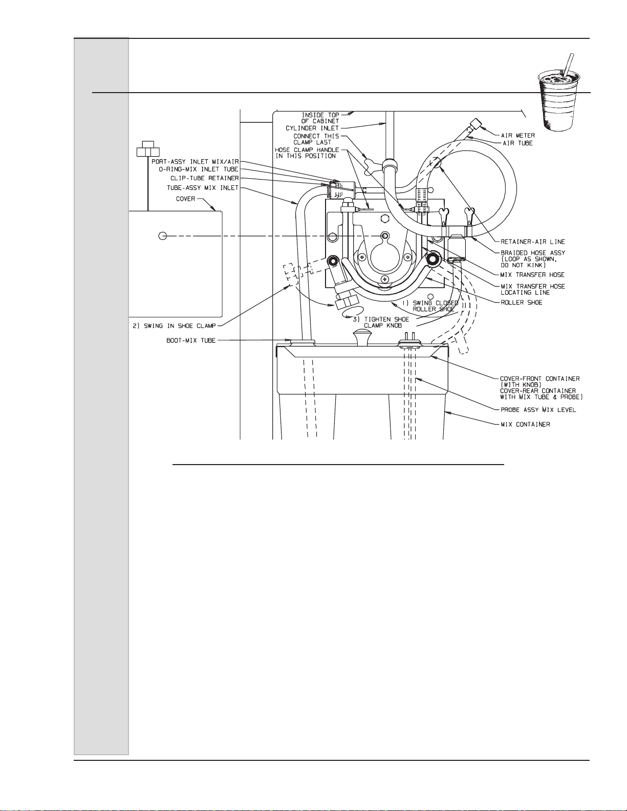
ELECTRO FREEZE Soft Serve Model GEN-2080
11 Assembly — Shake (continued)
Figure 11-7 MTS
21. Refer to gure 11-7. Install the
MTS hose assembly by rst placing the
clamp next to the braided hose, above
the roller bearing support on the right side
and push hose into slot. Place the transfer
hose under the rollers. While holding the
pickup tube stretch the hose so the left
hand clamp is above the roller bearing
support and push the hose into the slot.
Important:
Do not twist the hose assembly while
installing.
22. Check to ensure the transfer
hose is straight and centered on the
roller assembly making sure the locating
line is facing out. The line should be in
the same position at the inlet and outlet
guides of the roller bearing support, as
shown in gure 11-7.
23. Swing the shoe over hose and
tighten the swing clamp hand knob in
place until it bottoms out and will not turn
any further.
24. Insert the air tube into the
retainer in the back of the cabinet.
25. Insert the MTS cover over stud
see gure 11-8. Hose clamps should
be exposed. Tighten cover knob. Hand
tighten only.
Important:
The MTS will not operate unless the
cover is installed and secured by the
hand knob.
26. Loop the braided hose towards
you and slide the hose over the cylinder
inlet tube. Tighten the clamp. Make sure
the braided hose is not twisting transfer
hose.
— continued
185240 49

ELECTRO FREEZE Soft Serve Model GEN-2080
11 Assembly — Shake (continued)
Figure 7-8 MTS
Figure 11-8 MTS and Mix Tank
50 185240

ELECTRO FREEZE Soft Serve Model GEN-2080
12 Start-up Instructions — Soft Serve
12.1 Sanitizing Instructions — Soft Serve
CAUTION
Mix Transfer System will
be pressurized during
operation. Make sure all
components and fasteners
are secure before start-up.
The washing and sanitizing instructions
explained in this manual are important
procedures to remove bacteria and
maintain a clean, sanitary freezer. Always
sanitize prior to assembling to ensure the
best possible cleanliness.
CAUTION
To prevent bacteria growth,
use only approved sanitizers to sanitize the machine.
Sanitizing must be done just
prior to starting the machine.
Failure to do so could create
a health hazard.
3. Clean the interior mix tank
walls, the underside of the
tank covers and low mix
probes with sanitizer liquid and the
appropriate brush provided.
4. Place the mix tank in the refrigerated
cabinet. Fill with sanitizing solution.
Important:
Never let the sanitizer remain in the
freezer for more than 15 minutes.
5. Immerse the pickup tubes into
the sanitizer solution and sanitize
the outside portion. If plastic mix
bag systems are used, be sure all
adapters and items that will come in
contact with mix are sanitized.
6. Place an empty container under the
dispensing head.
7. Open the air bleed plugs by pulling up
until the plugs touch the bottom of the
switch box.
IMPORTANT:
Do not use unapproved sanitizers
or laundry bleach. These materials
may contain high concentrations of
chlorine and will chemically attack
freezer components.
NOTE: It is your responsibility to be
aware of and conform to the requirements
for meeting federal, state, and local laws
concerning the frequency of cleaning and
sanitizing the freezer.
1. Prepare 2 gallons (7.5 liters) of
sanitizing solution for each cylinder.
Sanitizing solution must be mixed
according to manufacturer’s
instructions to yield 100 PPM strength
chlorine solution (example: SteraSheen Green Label). Use warm water
(100° to 110°F or 37° to 43°C) to
wash, rinse, and sanitize.
2. Wash and sanitize your hands and
forearms.
8. Turn on the main power switch to the
freezer. The spigots must be closed.
Using the control panel press the L2
& R2 keys to turn the MTS pumps
“ON”. This will push the sanitizer up
into the cylinders.
9. When sanitizer ows out the bottom
of the head, close the air bleed plugs.
Important:
DO NOT use the “FREEZE” setting
with sanitizer in the cylinder. The
freezer will be damaged.
10. Using the control pad press the L1 &
R1 keys to turn the beaters “ON” and
allow the beaters to run for 5 minutes.
At this time check for leaks around
the head, drain tube,
clamps, and MTS.
11. Drain the solution from the cylinders
by slowly turning the spigot handles
open.
— continued
185240 51
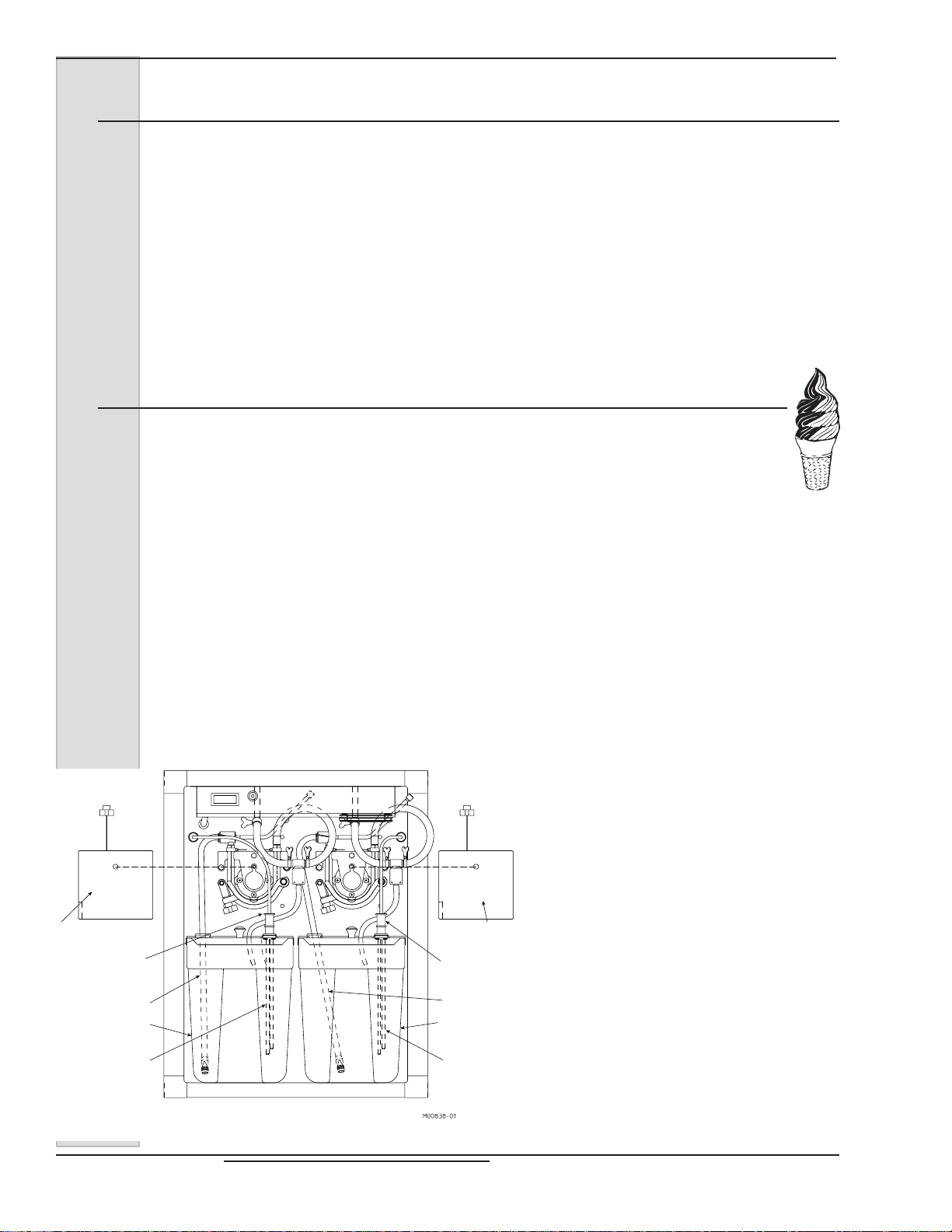
ELECTRO FREEZE Soft Serve Model GEN-2080
12.1 Sanitizing Instructions — Soft Serve(continued)
12. Leaving the spigots open, press L1
& R1 keys to turn the beaters “OFF”
and let the MTS force all possible
sanitizer out of the freezing cylinders.
NOTE: Some sanitizer will remain in
hoses and cylinder.
13. Press L2 & R2 keys to turn the MTS
pumps “OFF”.
12.2 Priming — Soft Serve
Priming the freezer removes all excess air and sanitizer from the freezing cylinder
and sets the proper overrun for the rst cylinder of product.
1. Wash and sanitize your hands and
forearms.
2. Holding the top 6-inch (15cm) portion
only, insert each pickup tubes into the
sanitized mix tank through the small hole
in the rear cover and set tanks in the
cabinet.
14. Remove the pickup tubes, holding the
top 6” portion only.
15. Remove the mix tanks and empty any
remaining sanitizer.
probes and to the back of the
cabinet.
6. Close the cabinet door.
7. Place an empty container under the
dispense head on the drip tray.
8. Pull up the air bleed plugs
Cover - Must be
in place to operate.
Mix Level
Probe Cord
Mix Pickup Tube
Mix Tank
Mix Level Probe
3. Slide each boot seal down on the mix
tank cover.
4. Fill the mix tanks with mix and install
the front covers.
5. Insert each sanitized mix probes
through the large hole in the rear cover,
and connect the probe cords to the
Mix Level
Probe Cord
Mix Pickup Tube
Mix Tank
Mix Level Probe
Cover - Must be
in place to operate.
9. Open the side spigots.
10. Press L2 & R2 keys to turn the MTS
pumps “ON” allowing the mix to push the
remaining sanitizer from the freezer.
11. Close the spigots one at a time when
pure mix is coming out.
Important:
Failure to completely remove
sanitizer or water from the freezing
cylinder before placing in “FREEZE”
will cause the scraper blades to break
and damage the freezer.
12. Allow the MTS to ll the cylinder
until mix ows from the bottom of the air
bleed plug openings in the bottom of the
dispense head, close the air bleed plugs.
Wait for the MTS to ll the cylinders and
shut off.
13. After the cylinders are pressurized
and the MTS has cycled off
(approximately 30 seconds) Press the left
and right “Freeze” keys.
14. Allow the freezer to cycle for 15
minutes. The product is now ready to
Figure 12-1
serve.
52 185240
ELECTRO FREEZE Soft Serve Model GEN-2080
13 Start-up Instructions — Shake
13.1 Sanitizing — Shake
CAUTION
Mix Transfer System will
be pressurized during
operation. Make sure all
components and fasteners
are secure before start-up.
The washing and sanitizing instructions
explained in this manual are important
procedures to remove bacteria and
maintain a clean, sanitary freezer. Always
sanitize prior to assembling to ensure the
best possible cleanliness.
CAUTION
To prevent bacteria growth,
use only approved sanitizers to sanitize the machine.
Sanitizing must be done just
prior to starting the machine.
Failure to do so could create
a health hazard.
3. Clean the interior mix
tank walls, the underside
of the tank covers and
low mix probes with sanitizer liquid
and the appropriate brush provided.
4. Place the mix tank in the refrigerated
cabinet. Fill with sanitizing solution.
Important:
Never let the sanitizer remain in the
freezer for more than 15 minutes.
5. Immerse the pickup tubes into
the sanitizer solution and sanitize
the outside portion. If plastic mix
bag systems are used, be sure all
adapters and items that will come in
contact with mix are sanitized.
6. Place an empty container under the
dispensing head.
7. Open the air relief plug by unscrewing
1½ turns.
IMPORTANT:
Do not use unapproved sanitizers
or laundry bleach. These materials
may contain high concentrations of
chlorine and will chemically attack
freezer components.
NOTE: It is your responsibility to be
aware of and conform to the requirements
for meeting federal, state, and local laws
concerning the frequency of cleaning and
sanitizing the freezer.
1. Prepare 2 gallons (7.5 liters) of
sanitizing solution for each cylinder.
Sanitizing solution must be mixed
according to manufacturer’s
instructions to yield 100 PPM strength
chlorine solution (example: SteraSheen Green Label). Use warm water
(100° to 110°F or 37° to 43°C) to
wash, rinse, and sanitize.
2. Wash and sanitize your hands and
forearms.
8. Turn on the main power switch to the
freezer. The spigots must be closed.
Using the control panel press the L2
& R2 keys to turn the MTS pumps
“ON”. This will push the sanitizer up
into the cylinders.
9. When sanitizer ows out of the air
relief hole, close the air relief plug.
Important:
DO NOT use the “FREEZE” setting
with sanitizer in the cylinder. The
freezer will be damaged.
10. Using the control pad press the L1 &
R1 keys to turn the beaters “ON” and
allow the beaters to run for 5 minutes.
At this time check for leaks around
the head, drain tube,
clamps, and MTS.
11. Drain the solution from the cylinders
by slowly turning the spigot handles
open.
— continued
185240 53

ELECTRO FREEZE Soft Serve Model GEN-2080
13.1 Sanitizing — Shake (continued)
12. Leaving the spigots open, press L1
& R1 keys to turn the beaters “OFF”
and let the MTS force all possible
sanitizer out of the freezing cylinders.
NOTE: Some sanitizer will remain in
hoses and cylinder.
13. Press L2 & R2 keys to turn the MTS
pumps “OFF”.
13.2 Priming — Shake
Priming the freezer removes all excess air and sanitizer from the freezing cylinder
and sets the proper overrun for the rst cylinder of product.
1. Wash and sanitize your hands and
forearms.
2. Holding the top 6-inch (15cm) portion
only, insert each pickup tubes into the
sanitized mix tank through the small hole
in the rear cover and set tanks in the
cabinet.
3. Slide each boot seal down on the mix
tank cover.
4. Fill the mix tanks with mix and install
the front covers.
5. Insert each sanitized mix probes
through the large hole in the rear cover,
and connect the probe cords to the
probes and to the back of the cabinet.
14. Remove the pickup tubes, holding the
top 6” portion only.
15. Remove the mix tanks and empty any
remaining sanitizer.
6. Close the cabinet door.
7. Place an empty container
under the dispense head on the
drip tray.
8. Open the air relief plug by unscrewing
1½ turns.
9. Open the plunger.
10. Press L2 & R2 keys to turn the MTS
pumps “ON” allowing the mix to push the
remaining sanitizer from the freezer.
11. Close the spigots one at a time when
pure mix is coming out.
Important:
Failure to completely remove
sanitizer or water from the freezing
cylinder before placing in “FREEZE”
will cause the scraper blades to break
and damage the freezer.
12. Allow the MTS to ll the cylinder
until mix ows from the bottom of the air
bleed plug openings in the bottom of the
dispense head, close the air bleed plugs.
Cover - Must be
in place to operate.
Mix Level
Probe Cord
Mix Level
Probe Cord
Cover - Must be
in place to operate.
Wait for the MTS to ll the cylinders and
shut off.
13. After the cylinders are pressurized
and the MTS has cycled off
Mix Pickup Tube
Mix Tank
Mix Level Probe
Mix Pickup Tube
Mix Tank
Mix Level Probe
(approximately 30 seconds) Press the left
and right “Freeze” keys.
14. Allow the freezer to cycle for 15
minutes. The product is now ready to
serve.
Figure 13-1
54 185240

ELECTRO FREEZE Soft Serve Model GEN-2080
13.3 Dispensing Shakes
Make sure each person dispensing
shakes reads the following instructions
before attempting to use the freezer.
Following these instructions will produce a
well blended, old-fashioned style shake.
CAUTION
Rotating metal shaft. To
avoid injury, use only paper
or plastic mixing containers.
Contact between shaft and
metal containers or malt
collars can cause shaft to
wear and break.
1. Pour the required amount of
avoring in the bottom of the cup. Firmly
hold the cup and place the mixer spinner
inside the cup all the way to the bottom.
CAUTION
To avoid injury, never place a
towel or any other material on
the rotating shaft to clean.
2. Pull the handle down toward you
as far as possible. Slowly lower the cup
as it lls with product. DO NOT open
and close the handle while ling the cup.
Always keep the spinner blade about on
inch in the product.
3. When the cup is full, close the
handle while lowering the cup and removing the spinner blade from the product,
allowing the product to spin off on the top
inside of the cup.
4. If additional mixing is required use
the manual push button (See gure 13-2 .
Your shake is now ready to serve.
Figure 13-2
185240 55
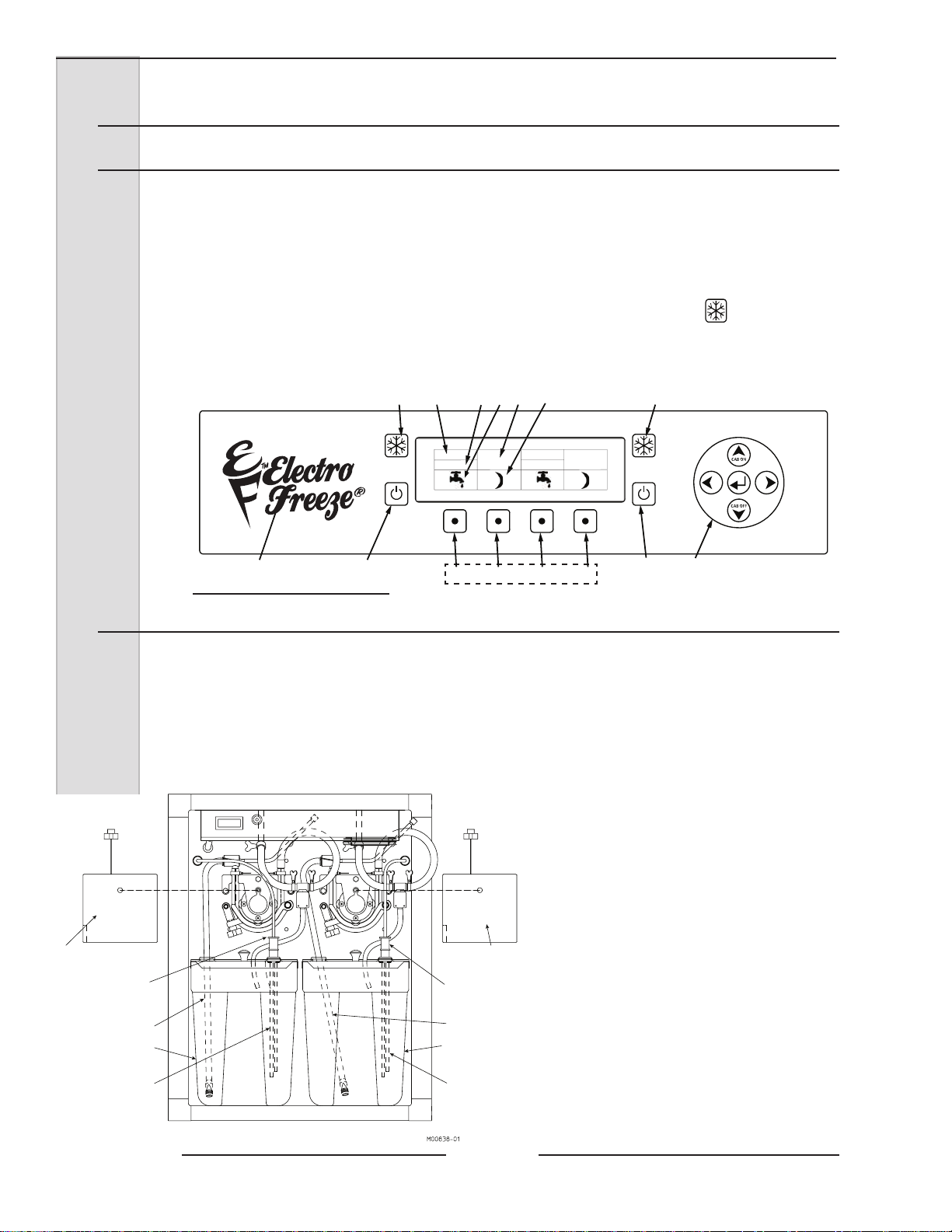
ELECTRO FREEZE Soft Serve Model GEN-2080
L1
23
45 6789
10
2
4
L2 R1 R2
1
LEFT RIGHT
OFF
OFF
14 Closing Procedures
14.1 Night Switch Operation
1. In areas where state and local
health codes will allow, the soft serve side
of model GEN-2080 may be switched to
standby, which will allow the freezer to
cycle all night and maintain approximately
38°F (3.3°C) or lower product in the
cylinder and cabinet.
2. To switch the freezer to the
standby mode press L2 or R2 (gure 14-1)
3. Remove serrated nozzle and
Figure 14-1
14.2 Draining Product
clean the drip tray assembly and all
soiled surfaces with soap and water. Use
sanitizing solution in a spray bottle and
brush to clean the bottom of the plunger
openings.
6. To start the machine after using
standby mode press 4 (gure 14-1).
Before replacing sanitized nozzle, use
a small brush and sanitizer to clean the
bottom of the plunger openings.
At the end of each day of operation, the freezer must be rinsed, sanitized, and
disassembled. The parts also must be washed, rinsed, sanitized, and prepared for
reassembly.
To remove frozen product from the
cylinders:
1. Press the L1 & R1 keys to enter
“CLEAN” mode.
2. In “CLEAN” mode press L1 & R1 to
turn the beaters on and let the beaters
run for 5 minutes. This will allow the
product in the cylinders to soften.
3. In the cabinet below (see gure 9-1).
Disconnect the mix probe cords from
the back of the cabinet.
4. Remove each mix tanks while pulling
the stainless steel pickup tube from
the mix tank. Place the pickup tubes
in a clean sanitized container.
Cover - Must be
in place to operate.
Mix Level
Probe Cord
Mix Pickup Tube
Mix Tank
Mix Level Probe
Cover - Must be
in place to operate.
Mix Level
Probe Cord
Mix Pickup Tube
Mix Tank
Mix Level Probe
5. Mix must be handled according to
local health codes.
6. Place a clean sanitized container
under the dispensing head.
7. Very slowly open the side spigots and
dispense the semi-frozen product until
it quits dispensing. To eliminate waste,
dispense as much as possible for use
in pints, quarts, and/or novelties.
Figure 14-1
— continued
56 185240
ELECTRO FREEZE Soft Serve Model GEN-2080
14.2 Draining Product (continued)
8. Close spigots. Press L2 & R2 to turn
the MTS pumps “OFF”.
9. Place the mix pickup tubes into a
container and ll with cold water. Turn
the MTS pumps “ON” and allow
the MTS to ll and pressurize the
cylinders.
CAUTION
Make sure the freezer is
depressurized before proceeding.
10. Very slowly open the spigots and
dispense the cold water. Follow
with a container of warm water and
repeat until the dispensed water is
clear. Drain remaining water from the
cylinders.
11. Turn the beaters and MTS pumps
“OFF”. Close the spigots
12. Prepare 2 gallons (7.5 liters) of
sanitizing solution for each cylinder.
Sanitizing solution must be mixed
according to manufacturer’s
instructions to yield 100PPM available
chlorine solution (example: SteraSheen Green Label). Use warm water
(100° to 110°F or 37° to 43°C).
IMPORTANT:
Do NOT use the “FREEZE”
position with sanitizer or water in
the cylinder. The freezer will be
damaged.
18. Slowly open the spigots and allow
the MTS to push the sanitizer out of
the cylinders. Leaving the spigots
open, turn the beaters “OFF”. Leave
the MTS pumps “ON” and allow the
pumps to force all remaining sanitizer
from the cylinders. When sanitizer
quits owing, place the MTS pump
switches to “OFF”
19. Remove the pickup tubes from the
sanitizing solution.
21. Refer to Disassembly and Cleaning
Instructions.
13. Insert the mix pickup tubes into the
sanitizing solution.
14. Place an empty container under the
dispense heads.
15. Pull the air bleed plugs up until they
touch the bottom of the switch box.
Open the spigots.
16. Turn the MTS pumps “ON”. When
sanitizer ows out the bottom of the
head, close the air bleed plugs and
allow the MTS to pressurize the
cylinders.
17. Press L1 & R1 to turn turn the beaters
“ON” and allow them to agitate for 5
minutes.
185240 57

ELECTRO FREEZE Soft Serve Model GEN-2080
15 Product Information
15.1 Overrun
As mix is frozen in the freezing cylinder,
air is incorporated into the mix to increase
its volume, as well as enhance the taste
and texture of the nished product. The
increase in volume is called overrun.
Fifty percent overrun means a volume
increase of 50% — 10 gallons of liquid
mix has become 15 gallons of nished
product.
Controlled overrun is important to
maintaining consistency in product quality.
Too much overrun (air) results in a light,
uffy product lacking the cold, refreshing
appeal of a quality product. Too little
overrun results in a soggy, heavy product.
To correctly measure the overrun, perform
the following steps:
1. Place an empty pint container on
the scale* and adjust your scale to zero.
2. Remove the container from the
scale and ll with liquid mix to the top.
Weigh the container and record.
3. Replace liquid mix with frozen
product, being sure to leave no voids or
air spaces in the container.
4. Strike off the excess product so it
is even with the top of the container and
measure the weight.
5. Use the following formula to gure
overrun percentage:
“Weight of liquid mix minus weight of
frozen product / divided by the frozen
weight.” See example:
Weight of one pint of mix = 18 oz.
Weight of one = 12 oz.
pint frozen product
Difference = 6 oz.
6.0 oz. divided by 12 oz. = .5
.5 x 100 = 50% overrun
* Your Electro Freeze Distributor can
provide a scale (P/N 158049) that is
graduated in overrun percentage.
58 185240

ELECTRO FREEZE Soft Serve Model GEN-2080
15.2 Overrun Adjustment
NOTE: Each person who operates the
freezer should know what overrun is
and how to calculate it.
Overrun is regulated by the air meter. The
four air meters supplied with the freezer
each have a different size orice. The
smaller the hole and number, the lower
the overrun. The larger the hole and
number, the higher the overrun. Each
half-size change of the air meter number
will change the overrun 3-5%; each fullsize change of the air meter number will
change the overrun 8-10%.
The orice or hole in this air meter must
be open at all times. It is the only source
of air into the freezing cylinder. Check this
daily!
The mix will be a factor in determining
the amount of overrun you will be able to
achieve. Some mixes will accept more air
than others, thus affecting the size of air
meter you can use. Test to see which air
meter will give you the best overrun and
the best product. Run each air meter for a
few hours until you decide.
You may have a slightly higher overrun
when you rst start up the machine.
After the machine has run long enough
to dispense at least one full cylinder of
product, you will have the overrun that
the machine will hold the remainder of
the day. Contact your mix supplier for the
recommended amount of overrun for each
product used.
15.3 Rerun
Rerun is product that has been drawn through the freezer into a container and has
melted down to be re-processed. If local health codes permit the use of rerun make
sure to follow these procedures:
1. Store rerun mix in a clean,
sanitized container.
2. Store in a cooler with a
temperature below 40ºF (4.4ºC).
3. DO NOT prime the machine with
rerun. Always skim off and discard foam.
Then combine the rerun with fresh mix
in a ratio of 50/50 and add to the mix
container during operation.
4. Once a week run the mix as low
as possible and discard after closing. This
will break the rerun cycle and reduce the
possibility of high bacteria and coliform
counts.
Figure 15-1 Air Meter
NOTE: Rerun product is unable to accept
the same amount of air as fresh product.
As a result, the quality will be affected and
product may appear grainy and icy.
For further information contact your local
Electro Freeze distributor or the Service
Department of H. C. Duke & Son, LLC.,
Electro Freeze, phone (309) 755-4553,
(800) 755-4545 OR E-MAIL service@
hcduke.com.
185240 59

ELECTRO FREEZE Soft Serve Model GEN-2080
16 Routine Maintenance
Electro Freeze recommends the following schedule to help maintain your Model
GEN-2080 Combination Soft Serve/Shake Freezer in like-new operating condition.
Take the time to learn and perform these routine procedures and receive in return
many years of valuable service from your freezer. Protect your investment!
DAILY
1. Disassemble, wash, rinse, sanitize, air dry, reassemble and sanitize all
parts that come into contact with the mix
or product.
CAUTION
To prevent bacteria growth,
remove ALL O-rings when
cleaning. Failure to do so
could create a health hazard.
2. Clean the cylinder inlet tube,
drain tube and mix tube with the appropriate brushes.
3. When cleaning, inspect all
O-rings, seals and hoses. Replace any
O-ring, seal or hose that is worn, torn, or
loose tting.
4. Wipe all exterior surfaces of the
freezer to remove any splattered mix.
WEEKLY
1. Carefully inspect all parts for
wear, including seals, O-rings, mix
transfer tubes, and blades.
2. Replace as required.
5mm
Replace blades if worn 5mm (3/16”) or
more.
3. Check the beater shanks
and drive coupling for wear.
5. Check overrun and temperature
of the product.
250 Hours of
Operation
A worn shank will have a nonparallel
1. Contact your local distributor for
the initial oil change of the gear reducer.
60 185240
shape on the drive opening.

ELECTRO FREEZE Soft Serve Model GEN-2080
16 Routine Maintenance - (continued)
AS NEEDED
CAUTION
To avoid electrical shock or
contact with moving parts,
make sure all switches are in
the “OFF” position and that
the main power supply is
disconnected. Some freezers
have more than one disconnect
switch.
1. Clean the mix transfer system:
If the transfer hose is assembled
improperly or replacement has been
neglected, it may be necessary to clean
mix from the MTS due to hose failure.
If this happens frequently the MTS should
be removed for complete cleaning.
a. Remove cover, loosen
swing clamp and open shoe to gain
access to the hose cavity.
Important:
CAUTION
Make sure the freezer
is depressurized before
proceeding.
b. Remove mix transfer
hose assembly.
c. Lay a towel on the
cabinet base below the MTS.
d. Using the spray bottle
supplied, ush the hose cavity and
roller assembly.
e. Use a brush (supplied)
to clean in between rollers. Flush
with sanitizer.
f. Wipe all surfaces with a
clean dry cloth.
g. Remove and clean
shoe. See gure 16-1.
Figure 16-1
185240 61

ELECTRO FREEZE Soft Serve Model GEN-2080
16 Routine Maintenance (continued)
MONTHLY
A. Testing the Head Switch
The head switch feature is designed
to prevent the beater shaft from being
accidentally activated. The beater
motors should not operate with the
head assembly removed. It is
essential that the proper operation of
this
switch be veried routinely. Use the
following instructions to test for proper
operation:
CAUTION
T o avoid electrical shock
or contact with moving
parts, make sure the
control pad is “OFF” and
that the power switch is
“OFF”.
1. Remove the dispense head
and beater shaft assemblies.
2. Place the power switch “ON”.
NOTE:
Do this test for each freezing
cylinder.
3. Press the and “BEATER
ON”. Look inside the cylinder at the rear
drive coupling for rotation. Press the
freeze button and look inside the
cylinder at the rear drive coupling for
rotation. Turn the “ BEATER OFF”.
Proper Operation
When “BEATER ON” is activated or the
freeze button is pushed, the
display should read “HEAD SWITCH”
and not allow coupling/beater shaft
rotation. The head switch is operating
properly. When the head is replaced
the system should reset and allow
beater rotation. Make sure the control
pad is “OFF” and that the power switch
is “OFF”. The freezer is ready to be
assembled and put in service.
Mechanical Hazard
CAUTION
Moving parts. Do not
place hands in the
freezing cylinder. Severe
personal injury could
result.
When “BEATER ON” is activated or the
freeze button is pushed and the
rear drive coupling is rotating and the
display does not read “HEAD
SWITCH”. Freezer has a head switch
or software problem. Turn the power
switch “OFF”. DO NOT place the
freezer in service until the problem has
been corrected.
B. Water Condenser
Check the outlet water
temperature of water-cooled
condensers at the oor drain. Ideal
water temperatures should be about
95°F (35°C) with a 70°F (21.1°C)
water inlet temperature.
62 185240
— continued

ELECTRO FREEZE Soft Serve Model GEN-2080
16 Routine Maintenance (continued)
MONTHLY (continued)
C. MTS Cover Switch
The MTS cover switch feature is designed
to prevent the MTS gear motor from being
accidentally activated. It is essential that the
proper operation of this switch be veried on a
routine basis. Use the following instructions to
test for proper operation:
NOTE: Freezer should be cleaned and
disassembled for this test.
1. Be sure all switches are in the “OFF”
position.
2. Remove the MTS cover to expose the
roller assembly.
3. Turn MTS switch to “ON”.
CAUTION
Make sure system is
depressurized before
proceeding.
“OFF” mix switch and discontinue use until
repairs can be made.
5. If there is no movement, slowly
install cover and listen for the gear motor
to turn on. The cover should be almost
completely closed when the gear motor
turns on. DO NOT insert ngers or
objects into roller cavity during this test. If
the MTS does not operate as described
here, or you are unable to determine if the
MTS is operating properly, turn the switches
to the “OFF” position, disconnect the main
power supply and contact your service
technician or the factory. DO NOT place
the freezer in service until the problem has
been corrected.
D. Replace the Mix Transfer
Hose
CAUTION
Make sure the freezer
is depressurized before
proceeding.
CAUTION
DO NOT place hands
near the MTS rollers.
Severe personal injury
could result.
4. Look at the MTS rollers; they should
NOT be rotating. If they are rotating, turn
CAUTION
To avoid electrical shock or
contact with moving parts, make
sure all switches are in the
“OFF” position and that the main
power supply is disconnected.
Some freezers have more than
one disconnect switch.
QUARTERLY
A. Air Condenser.
Important:
Never use a screwdriver or sharp
object to clean between ns.
Both air and water cooled freezers have
an air condenser. The condenser ns
need to be cleaned by your Electro
WARNING!
Failure to properly maintain/clean your air condenser can cause
premature compressor failure. Compressor failure due to improper
condenser care will void the compressor warranty.
Freeze Distributor to remove dirt, lint and
dust.
B. Refrigeration System
Have your Electro Freeze Distributor check
the refrigeration system and make any
necessary adjustments.
185240 63
ELECTRO FREEZE Soft Serve Model GEN-2080
16 Routine Maintenance (continued)
SEMIANNUALLY
1
. Contact your Electro Freeze distributor
to replace drive belts.
2. On air cooled and air cooled remote
freezers have your Electro Freeze distributor
check the condenser fan motor oil.
3. Have the gear reducer oil changed by
your Electro Freeze distributor.
NOTE: Under normal conditions, after the
initial change, the oil should be changed
after every 2500 hours of operation or
every six months, whichever occurs rst.
ANNUALLY
CAUTION
To avoid electrical shock or
contact with moving parts,
make sure all switches are
in the “OFF” position and
that the main power source
is disconnected. Some
freezers have more than one
disconnect switch.
1. Call your Electro Freeze
Distributor for service to replace drive
belts and lubricate fan motor as needed.
2. Call your Electro Freeze
Distributor to clean the inside of the
freezer including base, side panels,
condenser, etc.
3. Call your Electro Freeze
Distributor to check water-cooled
condensers and ush clean to remove
scale and deposits if necessary.
64 185240
ELECTRO FREEZE Soft Serve Model GEN-2080
16 Routine Maintenance (continued)
Winter Storage
To protect the unit during seasonal shutdown, it is important to store the
GEN-2080 Combination Soft Serve/Shake Freezer properly. Please use
the following procedures:
1. Disconnect all power to the freezer.
2. Disassemble and wash all parts that come into contact with the mix
with a warm, mild detergent solution. Rinse in clear water and dry all parts
thoroughly.
3. Store the loose parts, such as the head assembly, beater
assembly, and pump parts in a safe, dry place.
4. Do not lay heavy objects on the plastic or rubber parts.
5. Cover the freezer and all loose parts to protect them from dust or
other elements that could contaminate them while in storage. Place the
freezer in a dry location.
6. On air-cooled freezers, have condenser ns cleaned by an
authorized service technician.
Important:
The water valve must be opened in order to blow out the condenser.
Failure to purge the freezer of water can result in severe damage
to the refrigeration system. Call your Electro Freeze Distributor for
service.
7. On water-cooled freezers, disconnect the water supply. Use
compressed air to blow out all remaining water in the condenser.
8. When freezer is restarted after seasonal shutdown, remember to
replace all O-rings and seals with new parts. Rubber parts can lose their
elasticity and ability to seal when they are stored.
USE ONLY ORIGINAL OR AUTHORIZED REPLACEMENT PARTS WITH THIS FREEZER.
(See your Illustrated Replacement Parts Manual)
Should you have any questions on items that are not included in this maintenance schedule, or
problems where service assistance is needed, please call your local Electro Freeze Distributor or
H. C. Duke & Son, LLC. Electro Freeze Service Department, for factory service at (309) 755-4553
or (800) 755-4545.
185240 65

ELECTRO FREEZE Soft Serve Model GEN-2080
17 Troubleshooting Tables
SAFETY
THIS SAFETY ALERT SYMBOL IDENTIFIES
IMPORTANT PERSONAL SAFETY MESSAGES IN
THIS MANUAL. WHEN YOU SEE THIS SYMBOL,
BE ALERT TO THE POSSIBILITY OF PERSONAL
INJURY. DO NOT ATTEMPT TO CONTINUE UNTIL
THE SAFETY PRECAUTIONS ARE THOROUGHLY
UNDERSTOOD.
Caution
All maintenance adjustments must be done
by an Electro Freeze Distributor or authorized
service technician.
Caution
To avoid electrical shock or contact with moving
parts, make sure all switches are in the “OFF”
position and that the main power supply is
disconnected. Some freezers have more than
one disconnect switch.
Important:
Some refrigerants are hazardous to the earth’s
atmosphere. To protect our environment, use
a refrigerant recovery/recycling unit whenever
removing refrigerant from the system.
66 185240
ELECTRO FREEZE Soft Serve Model GEN-2080
17 Troubleshooting Tables (continued)
PROBLEM PROBABLE CAUSE REMEDY
1. Freezer unplugged. 1. Plug in freezer.
Make sure your freezer is connected
to a separate circuit independent from
any other electrical equipment. Have
2.
technician check fuse or breaker
size and check for low voltage; if not
within 10% of nameplate rating call
power company.
Press overload reset button. Check
product temperature. (Note: cabinet
will continue to cool.)
Press overload reset button. If freezer
still does not operate contact your
Electro Freeze Distributor for service.
Unit does not
operate.
Fuse or breaker blown at main
2.
disconnect.
3. Beater motor out on overload. 3.
4. Control circuit overload open. 4.
Mix or water
leaking from
drain tube to
drip tray.
Mix leaking
at dispensing
head.
Off on high pressure cut-out or low
5.
pressure cut-out control.
6. Component failure. 6.
7. Faulty selector switch. 7.
Disconnected or broken wire in electrical
8.
circuit.
Damaged beater shaft seal or installed
1.
improperly.
Beater shaft pitted or damaged where
2.
o-ring rides.
3. Beater shaft end play not set properly. 3.
1. Faulty head o-ring. 1. Replace o-ring.
2. Head not properly installed. 2.
Contact your Electro Freeze
5.
Distributor for service.
Contact your Electro Freeze
Distributor for service.
Contact your Electro Freeze
Distributor for service.
Contact your Electro Freeze
8.
Distributor for service.
Replace cup seal or o-ring inside
1.
bushing. Install properly.
2. Replace beater shaft.
Contact your Electro Freeze
Distributor for service.
Install head properly. Replace o-ring
if pinched.
Dirty or blocked condenser, restricted air
1.
Dispensed
product too
soft. (Product
temperature
above 19°F)
185240 67
ow.
2. Component failure. 2.
Leak in refrigeration system resulting in
3.
little or no refrigeration.
Unblock condenser or have cleaned
1.
by your Electro Freeze Distributor.
Contact your Electro Freeze
Distributor for service.
Contact your Electro Freeze
3.
Distributor for service.
ELECTRO FREEZE Soft Serve Model GEN-2080
17 Troubleshooting Tables (continued)
PROBLEM PROBABLE CAUSE REMEDY
1. MTS pressure too low. 1. See MTS Troubleshooting Charts.
Check product temperature. Should
Product
dispenses
slowly out of
dispensing
head.
2. Product too cold. 2.
3. Low overrun. 3.
4. Wrong rotation on beater. 4.
be 18°F (-7.8°C). See Dispensed
Product Too Hard.
Check air meter. If plugged, clean.
See No Air (Overrun).
Have an electrician correct rotation to
clockwise as viewed from the front of
the freezer.
Dispensed
product too hard.
Freezer runs
continually
and product
continues to
get colder.
1. Low overrun. 1.
Cylinder thermostat erratic or set too
2.
cold.
Spigot switch electrically or
3.
mechanically stuck closed. (Unit runs all
the time.)
4. Component failure. 4.
Low suction pressure, refrigeration
5.
system.
1. Spigot switch rod engaged. 1. Close spigot completely.
2. Spigot not seated in head. 2. Push spigot down.
Spigot switch out of adjustment or
3.
defective.
Faulty thermostat or bulb not deep
4.
enough in well.
5. Starter or relay contact points stuck. 5.
Check overrun, if low see MTS
Troubleshooting Chart.
Contact your Electro Freeze
2.
Distributor for service.
Contact your Electro Freeze
3.
Distributor for service.
Contact your Electro Freeze
Distributor for service.
Contact your Electro Freeze
5.
Distributor for service.
Contact your Electro Freeze
3.
Distributor for service.
Contact your Electro Freeze
4.
Distributor for service.
Contact your Electro Freeze
Distributor for service.
6. Faulty time delay. 6.
7. Suction pressure too low. 7.
68 185240
Contact your Electro Freeze
Distributor for service.
Contact your Electro Freeze
Distributor for service.
ELECTRO FREEZE Soft Serve Model GEN-2080
17 Troubleshooting Tables (continued)
PROBLEM PROBABLE CAUSE REMEDY
Poor or slow
product recovery.
Compressor
does not operate
or operates
improperly.
Dirty or blocked condenser, restricted air
1.
ow – high ambient temperature.
Thermostat cut-in point out of adjustment
2.
or malfunctioning.
Defective condenser fan motor (air
3.
cooled)
4. Component or compressor failure. 4.
1. Trouble in compressor condensing circuit 1.
Faulty start capacitor, run capacitor or
2.
relay. (Single phase only)
3. Faulty contactor 3.
Disconnected or broken wire in switch or
4.
capacitor relay box.
1.
2.
3.
2.
4.
Have condenser cleaned by your
local service company; lower ambient
temperature.
Contact your Electro Freeze
Distributor for service.
Contact your Electro Freeze
Distributor for service.
Contact your Electro Freeze
Distributor for service.
Contact your Electro Freeze
Distributor for service.
Contact your Electro Freeze
Distributor for service.
Contact your Electro Freeze
Distributor for service.
Contact your Electro Freeze
Distributor for service.
1. Head assembly is not installed. 1. Install head assembly.
Beater motor
does not operate.
Compressor and
beater motor
operates only
when dispensing.
185240 69
2. Magnetic head switch defective. 2.
3. Component failure. 3.
Cylinder thermostat setting too warm or
1.
thermostat defective.
Contact your Electro Freeze
Distributor for service.
Contact your Electro Freeze
Distributor for service.
Contact your Electro Freeze
1.
Distributor for service.

ELECTRO FREEZE Soft Serve Model GEN-2080
17 Troubleshooting Tables (continued)
PROBLEM PROBABLE CAUSE REMEDY
Compressor and
beater motor do
not operate when
dispensing.
Cabinet too
cold. (below
35°F [1.7°C])
Spigot switch(es) defective or out of
1.
adjustment.
2. Component failure. 2.
1. Cabinet setting too low. 1.
2. Defective thermostat. 2.
3. Cabinet solenoid stuck open 3.
4. Cabinet expansion valve set too low. 4.
Cabinet thermostat defective, set too
1.
warm or tuned off.
1.
1.
Contact your Electro Freeze
Distributor for service.
Contact your Electro Freeze
Distributor for service.
Contact your Electro Freeze
Distributor for service.
Contact your Electro Freeze
Distributor for service.
Contact your Electro Freeze
Distributor for service.
Contact your Electro Freeze
Distributor for service.
Contact your Electro Freeze
Distributor for service.
Cabinet solenoid defective (does not
2.
open).
3. Cabinet switch defective. 3.
Mix sours in
cabinet.
70 185240
4. Door switch defective. 4.
Cabinet compressor contactor coil open
5.
(mix sours in night mode only.
6. Faulty time delay. 6.
7. Suction pressure too low. 7.
Contact your Electro Freeze
2.
Distributor for service.
Contact your Electro Freeze
Distributor for service.
Contact your Electro Freeze
Distributor for service.
Contact your Electro Freeze
5.
Distributor for service.
Contact your Electro Freeze
Distributor for service.
Contact your Electro Freeze
Distributor for service.
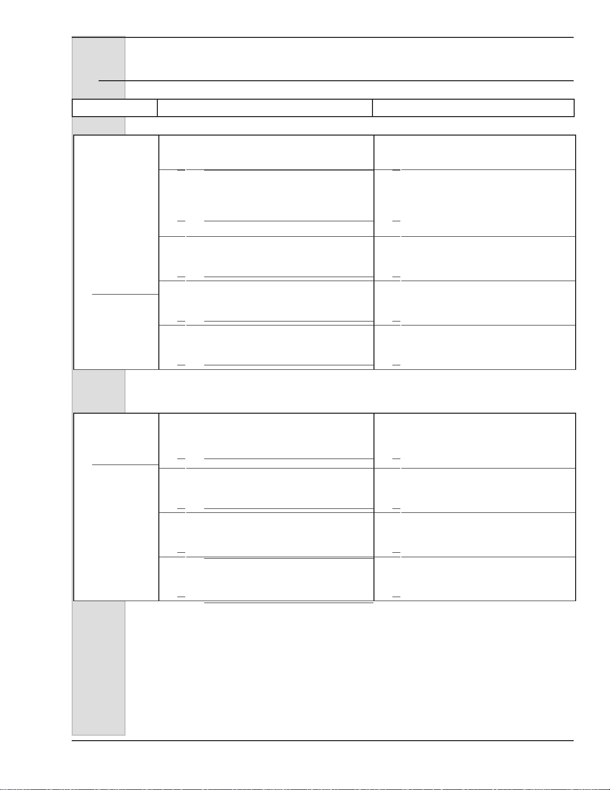
ELECTRO FREEZE Soft Serve Model GEN-2080
17 Troubleshooting Tables (continued)
PROBLEM PROBABLE CAUSE REMEDY
Compressor will
not start – hums
intermittently
(cycling on
overload)
Compressor
starts, but remain
in start windings.
1. Improperly wired. 1.
2. Low line voltage. 2.
3. Open start capacitor. (Single phase only) 3.
4. High discharge pressure. 4.
5. Defective compressor 5.
1. Low line voltage. 1.
Contact your Electro Freeze
Distributor for service.
Ask power company to increase
voltage to not less than 10% below
dataplate rating or have transformer
installed. Have wire checked for
inadequate wire size.
Contact your Electro Freeze
Distributor for service.
See "Discharge pressure too high"
this section.
Contact your Electro Freeze
Distributor for service.
Ask power company to increase
voltage to not less than 10%
below nameplate rating or install
transformer.
2. Improperly wired. 2.
Running capacitor shorted. (Single phase
3.
only).
Start capacitor weak. (Single phase
4.
only).
185240 71
Contact your Electro Freeze
Distributor for service.
Contact your Electro Freeze
3.
Distributor for service.
Contact your Electro Freeze
4.
Distributor for service.

ELECTRO FREEZE Soft Serve Model GEN-2080
17 Troubleshooting Tables (continued)
PROBLEM PROBABLE CAUSE REMEDY
Discharge
pressure too high.
Water hose kinked or pinched. (water
1.
cooled models)
Water turned off or defective water
2.
regulating valve. (water cooled models)
Restricted water cooled condenser.
3.
(water cooled models)
4. Dirty air condenser. (air cooled models) 4.
Unit location too warm (air cooled
5.
models)
6. Refrigerant overcharge. 6.
7. Air in system. 7.
1.
2.
3.
5.
Move freezer and adjust hose so it is
not pinched or kinked.
Turn on water, or contact your Electro
Freeze Distributor for service.
Contact your Electro Freeze
Distributor for service.
Contact your Electro Freeze
Distributor for service.
Contact your Electro Freeze
Distributor for service.
Contact your Electro Freeze
Distributor for service.
Contact your Electro Freeze
Distributor for service.
Discharge
pressure too low.
Noisy
compressor.
Water regulating valve open too wide.
1.
(water cooled model)
2. Shortage of refrigerant. 2.
1. Tubing rattles. 1.
2. Spring broken internally. 2.
1.
Contact your Electro Freeze
Distributor for service.
Contact your Electro Freeze
Distributor for service.
Contact your Electro Freeze
Distributor for service.
Contact your Electro Freeze
Distributor for service.
NOTE: Contact your authorized Electro Freeze Distributor for instructions
prior to warranty compressor replacement.
72 185240

ELECTRO FREEZE Soft Serve Model GEN-2080
17.1 MTS Troubleshooting Tables
PROBLEM PROBABLE CAUSE REMEDY
Remove cover, clean inside MTS
Mix leaks out of
MTS.
1. Transfer hose worn or split. 1.
1. Pump cover not installed. 1. Install cover.
2. Hose not installed properly. 2. Check position – reinstall.
around rollers with spray bottle
provided. Install new hose. Do not
twist hose.
Mix transfer
system (MTS)
will not operate.
MTS will not
shut off.
MTS cycles on
and off without
dispensing.
3. Slide switch defective. 3.
4. MTS relay defective. 4.
Start capacitor defective or motor start
5.
switch defective.
6. Pressure switch defective. 6.
Motor defective or internal overload
7.
tripped.
1. Hose broken. 1. Replace hose.
2. Pressure switch stuck in closed position. 2.
1. Worn transfer hose. 1. Replace hose.
2. Leak on pressure side of system. 2.
Contact your Electro Freeze
Distributor for service.
Contact your Electro Freeze
Distributor for service.
Contact your Electro Freeze
5.
Distributor for service.
Contact your Electro Freeze
Distributor for service.
Contact your Electro Freeze
7.
Distributor for service.
Contact your Electro Freeze
Distributor for service.
Contact your Electro Freeze
Distributor for service.
1. Insufcient supply of mix. 1. Replenish mix supply.
MTS will not
prime.
Mix pickup tube
loses prime.
185240 73
2. Swing clamp knob loose. 2. Tighten knob.
3. Air hose or air meter not installed. 3. Install air hose/air meter.
4. Hose not installed. 4. Install hose.
1. Defective or missing duckbill valve. 1. Replace duckbill valve.
2. Inlet clamp not tight. 2. Tighten clamp.
3. Worn transfer hose. 3. Replace transfer hose.

ELECTRO FREEZE Soft Serve Model GEN-2080
17.1 MTS Troubleshooting Tables
PROBLEM PROBABLE CAUSE REMEDY
1. Air meter plugged. 1. Clean or replace air meter.
No air (overrun).
2. Air tube pinched. 2. Replace tube.
1. Air meter too large. 1. Install smaller air meter.
Too much air,
overrun too
high – popping
problems.
Mix shoots out
air meter.
2. Air leak between pickup tube and hose. 2. Replace as needed.
3. Air line hose cracked – sucking air. 3. Replace air line hose.
4. Defective or missing duckbill valve. 4. Replace valve.
1. Swing Clamp knob loose. 1. Tighten.
2. Transfer hose worn. 2. Replace hose.
3. MTS pressure too high. 3.
Contact your Electro Freeze
Distributor for service.
Keep your freezer in excellent
condition — always contact
your Electro Freeze Distributor
QUALITY PARTS
PROTECT
YOUR
for replacement parts and
maintenance scheduling.
INVESTMENT
NOTE: Contact your authorized Electro Freeze Distributor for
instructions prior to warranty compressor replacement.
74 185240

ELECTRO FREEZE Soft Serve Model GEN-2080
18 VQM Error Codes
Error Code Description/Action Probable Cause Remedy
Main Comm The Main P.C. Board
has stopped receiving
messages from the User
Interface
Action: System shut
down completely.
1. Faulty Wire
Connection
2.Programming Issue
3. Defective Board
1. Check Communication cable
between Main P.C. board and U.I.
board. (Contact Electro Freeze
Factory Tech Support)
2. Ensure U.I. Program version
and Main P.C. Program Version are
compatible. (Contact Electro Freeze
Factory Tech Support Software version
compatibility)
3. If the program versions are
compatible, and using the test cable
does not resolve the issue then the
main control board is not functioning
properly and needs to be replaced.
(Contact Electro Freeze Factory Tech
Support)
NO Comm. The U.I. Board is not re-
ceiving messages from
the main board
Action: System shut
down completely.
1. Faulty Wire
Connection
2.Programming Issue
3. Defective Board
1. Check Communication cable
between Main P.C. board and U.I.
board. (Contact Electro Freeze
Factory Tech Support)
2. Ensure U.I. Program version
and Main P.C. Program Version are
compatible. (Contact Electro Freeze
Factory Tech Support)
3. If the program versions are
compatible, and using the test cable
does not resolve the issue then the
U.I. board is not functioning properly
and needs to be replaced. (Contact
Electro Freeze Factory Tech Support)
185240 75

ELECTRO FREEZE Soft Serve Model GEN-2080
18 VQM Error Codes (continued)
Error Code Description/Action Probable Cause Remedy
CYL Rfg. This error occurs when
barrel system run time
exceeds 90 minutes.
Barrel switches to night
mode and locks out.
Action: Barrel
Refrigeration off, hopper
refrigeration continues
to operate.
1. Dirty Condenser
2. Shortage of
Refrigerant
3. Faulty wire
connection
4. Solenoid valve not
activating
1. Clean Condenser
2. Locate Source of refrigerant leak
and repair.
3. Locate faulty connection (Wire
rubbed through, cut) and repair as
needed.
4. Determine if Solenoid coil is
receiving proper voltage (208/230
Volts), If coil is receiving voltage,
ohm out coil windings. If coil is
not receiving voltage, check relay
responsible for activating coil and
repair as needed. If this condition
exists a LOW PSI error code may also
trip.
5. Compressor starting
components failure (1
Phase Only)
6. Compressor
Contactor Failure
7. Compressor
Contactor Control Relay
not activating
8. System lacks
efciency
9.Faulty Thermistor
5. Check Compressor Starting
components and replace as
needed.
6. Check contactor coil for proper
resistance, check for voltage drop
across contact points. Replace as
needed
7. Check to see if Relay is receiving
power from Main P.C. board (12VDC),
Ohm relay control coil for proper
resistance. Replace relay as needed.
If no 12VDC is detected Contact
Electro Freeze Factory Tech Support.
8. Check for worn blades, AXV
pressure settings, Check water
regulating valve setting (Water
Cooled), check refrigerant level,
compressor efciency.
9. Remove thermistor, check in ice
water and compare to thermistor curve
chart. If faulty replace, if thermistor
tests o.k. check wire harness
connections. If all connections are
sound possibility of control board
issue. (Contact Electro Freeze for
proper compressor oil charge)
76 185240

ELECTRO FREEZE Soft Serve Model GEN-2080
18 VQM Error Codes (continued)
Error Code Description/Action Probable Cause Remedy
CYL Rfg. This error occurs when
barrel system run time
exceeds 90 minutes.
Barrel switches to night
mode and locks out.
Action: Barrel
Refrigeration off, hopper
refrigeration continues
to operate.
10. Condenser Fan
Motor Failure (Air
Cooled Only)
11. Water Flow
Restriction (Water
Cooled Only)
12. AXV not set
properly/not responding
13. Compressor Failure/
Reduced Capacity
10. Replace Condenser fan motor
11. Locate and remove restriction, restart system to check for further issues
12. Check System refrigerant level,
attempt to re-set AXV valve pressure.
If valve is not responsive, it may need
to be replaced
13. Check Voltage to the unit to
ensure it is within specication,
Check wire connections to the unit
and compressor, Check compressor
contactor for loose wire connections
and proper operation, and possible
voltage drop, ohm compressor
windings to check for a short and
proper winding resistance, check
compressor starting components for
failure, allow compressor protector to
reset and check for proper amp draw.
Cabinet Rfg Occurs when cabinet
system run time
exceeds 90 minutes
Action: Barrel
refrigeration switches
to night mode, cabinet
refrigeration is turned
off.
14. Moisture in system
1. Dirty Condenser
2. Shortage of
Refrigerant.
3. Evaporator coil Froze
up
4. Faulty wire
connection
5. Restriction in System
i.e. Capillary tube, Filter
Drier
14. Recover refrigerant, change lter
drier, change compressor oil (Contact
Electro Freeze for proper compressor
oil charge), Evacuate system to a
minimum of 200 microns or less.
Repeat if necessary
1. Clean Condenser
2. Locate Source of refrigerant leak
and repair.
3. Check door gasket for wear, check
evaporator fan motor for proper
operation, check spring loaded door
closer for proper operation.
4. Locate faulty connection (Wire
rubbed through, cut) and repair as
needed.
5. Locate restriction and repair as
needed.
185240 77

ELECTRO FREEZE Soft Serve Model GEN-2080
18 VQM Error Codes (continued)
Error Code Description/Action Probable Cause Remedy
Cabinet Rfg
(cont.)
Occurs when cabinet
system run time
exceeds 90 minutes
Action: Barrel
refrigeration switches
to night mode, cabinet
refrigeration is turned
off.
6.Faulty Thermistor
7. Compressor Control
Relay not activating
6. Remove thermistor, check in ice
water and compare to thermistor curve
chart. If faulty replace, if thermistor
tests o.k. check wire harness
connections. If all connections are
sound possibility of control board
issue. (Contact Electro Freeze Factory
Tech Support)
7. Check to see if Relay is receiving
power from Main P.C. board (12VDC),
Ohm relay control coil for proper
resistance. Replace relay as needed.
If no 12VDC is detected Contact
Electro Freeze Factory Tech Support.
Bulb Temp. Occurs when barrel
thermistor is above or
below temp. limit for 1
minute without change
Action: Affected barrel
is in night time cycle
mode (1min on and
40 min. off), Cabinet
refrigeration remains on
8. Compressor starting
components failure
9. Compressor failure/
reduced capacity
10. Moisture in System
1. Faulty wire
connection
2. Faulty Thermistor
3. Program Issue
8. Check Compressor Starting
components and replace as needed.
9. Check Voltage to the unit to
ensure it is within specication,
Check wire connections to the unit
and compressor, Check compressor
contactor for proper operation,
and possible voltage drop, ohm
compressor windings to check
for a short and proper winding
resistance, check compressor
starting components for failure, allow
compressor protector to reset and
check for proper amp draw.
10. Recover refrigerant, change lter
drier, change compressor oil (Contact
Electro Freeze for proper compressor
oil charge), Evacuate system to a
minimum of 200 microns or less.
Repeat if necessary
1. Locate faulty connection (Wire
rubbed through, cut) and repair as
needed.
2. Remove thermistor, check in ice
water and compare to thermistor curve
chart. If thermistor does not ohm
correctly, replace thermistor.
3. Ensure U.I. Program version
and Main P.C. Program Version are
compatible. (Contact Electro Freeze
Factory Tech Support)
78 185240

ELECTRO FREEZE Soft Serve Model GEN-2080
18 VQM Error Codes (continued)
Error Code Description/Action Probable Cause Remedy
Cabinet T emp. Occurs when cabinet
thermistor is above or
below temp. limit for 1
minute without change
Action: Cabinet is in
time cycle mode (5 min.
on and 30 min. off) both
cylinders are in standby
mode.
If unit is in cabinet only
mode: Cabinet is in time
cycle mode and both
cylinders remain off
1. Faulty wire
connection
2. Faulty Thermistor
3. Program Issue
1. Locate faulty connection (Wire
rubbed through, cut) and repair as
needed.
2. Remove thermistor, check in ice
water and compare to thermistor curve
chart. If thermistor does not ohm
correctly, replace thermistor.
3. Ensure U.I. Program version
and Main P.C. Program Version are
compatible. (Contact Electro Freeze
Factory Tech Support)
Head Switch Occurs when head
switch is open with
power applied to unit
Action: Affected head is
turned off.
Motor OVLD Occurs when motor
current is 0, and motor
is given an on signal
Action: Affected barrel is
off, hopper refrigeration
continues to operate.
1. Head Assembly Not
installed
2. Faulty Head switch (1
per cylinder)
3. Faulty wire
connection
4. Program Issue
1. Motor internal
overload open
2. Faulty wire
connection
3. Motor Contactor
Failure
1. Install Head assembly
2. Test head switch to see if circuit
remains open with magnet in place,
remove and replace head switch as
needed
3. Locate Faulty wire connection and
repair as needed
4. Ensure U.I. Program version
and Main P.C. Program Version are
compatible. (Contact Electro Freeze
Factory Tech Support)
1. Allow motor to cool and overload to
reset, Check motor start components,
product temperature (Too cold, low
overrun), and gear reducer operation.
2. Locate Faulty wire connection and
repair as needed
3. Check contactor coil for proper
resistance, check for voltage drop
across contact points. Replace as
needed
4. Motor control relay
not activating
185240 79
4. Check to see if Relay is receiving
power from Main P.C. board (12VDC),
Ohm relay control coil for proper
resistance. Replace relay as needed.
If 12 VDC is not detected Contact
Electro Freeze Factory Tech Support
ELECTRO FREEZE Soft Serve Model GEN-2080
18 VQM Error Codes (continued)
Error Code Description/Action Probable Cause Remedy
Motor OVLD
(cont.)
Occurs when motor
current is 0, and motor
is given an on signal
5. Motor Failure
5. Check motor starting components,
check motor for shorts to ground,
check for proper winding resistance.
Replace Motor as needed
Comp. Low
PSI
Action: Affected barrel is
off, hopper refrigeration
continues to operate.
Occurs when low
pressure control is
activated.
Action: Cylinder
refrigeration is off,
Cabinet refrigeration
Continues to operate.
6. Current Sense board/
function failure
7. One line of power
loss
8. Program Issue
1. System is Short on
refrigerant
2. Solenoid valve not
activating
6. Check current sense board wire
connections, check max current
setting in control system. (Contact
Electro Freeze Factory Tech Support)
7. Check main power supply, and
main wire connections and correct as
needed
8. Ensure U.I. Program version
and Main P.C. Program Version are
compatible. (Contact Electro Freeze
Factory Tech Support)
1. Locate refrigerant leak and repair as
needed. Ensure refrigeration system is
evacuated to at least 200 microns.
2. Determine if Solenoid coil is
receiving proper voltage (208/230
Volts), If coil is receiving voltage,
ohm out coil windings. If coil is
not receiving voltage, check relay
responsible for activating coil and
repair as needed.
3. Low pressure control
is Faulty.
4. Restriction is
refrigeration system.
5. Faulty wire
connection.
6. System component
failure
80 185240
3. Conrm Low pressure control is
faulty by installing manifold gages to
conrm suction pressure is above cut-
in set point of control. Replace control
as needed
4. Locate and remove restriction i.e.
restricted drier, AXV closed down,
Solenoid valve not opening etc.
5. Repair connection as needed i.e.
faulty connection on LPCO, etc.
6. Locate failed component
(Diagnostics Mode in Technician
Menu will aid in locating) i.e. solenoid
coil, AXV valve not opening, control
relay, Compressor contactor staying
energized causing unit to pump down,
etc. and repair as needed.
ELECTRO FREEZE Soft Serve Model GEN-2080
18 VQM Error Codes (continued)
Error Code Description/Action Probable Cause Remedy
Comp. High
PSI
Occurs when the High
pressure control is
activated.
1. Dirty Condenser Air
Cooled
1. Blow out and clean Air cooled
condenser re-start system and check
unit operation.
Action: Cylinder
refrigeration is off,
Cabinet refrigeration
Continues to operate
2. Bad Condenser Fan
Motor (A/C Only)
3. Dirty Condenser
(Water Cooled)
4. High Pressure control
is Faulty.
5. Faulty Wire
Connection
6. Non-Condensables in
refrigeration system.
2. Replace Condenser motor as
needed. Check system operation
3. Check inlet and outlet water
temperature on condenser, it should
be at least 20°F difference from inlet
to outlet. If there is no temperature
change, condenser is fouled out and
will need to be cleaned, or changed.
If this condition is present, contact the
Electro Freeze Technical Support Line.
4. Conrm High pressure control is
faulty by installing manifold gages to
conrm high side pressure is below
cut-out set point of control. Replace
control as needed.
5. Repair connection as needed i.e.
faulty connection on HPCO, etc.
6. Fully recover refrigerant from
system, change the refrigerant lter/
drier, evacuate system to at least
200 microns and weigh in Factory
refrigerant charge (Contact Electro
Freeze in charge amount is not stated
on machine data Plate). Ensure while
evacuating system a manual activation
magnet is placed on each solenoid to
ensure they are open for a full system
evacuation. Start system and check
operation
7. Refrigeration System
over charged.
185240 81
7. Fully recover refrigerant from
system, change the refrigerant lter/
drier, evacuate system to at least
200 microns and weigh in Factory
refrigerant charge (Contact Electro
Freeze if charge amount is not stated
on machine data Plate). Start system
and check operation

ELECTRO FREEZE Soft Serve Model GEN-2080
18 VQM Error Codes (continued)
Error Code Description/Action Probable Cause Remedy
Clock Error CLOCK ERROR
Action: All timer
functions use default
data/time
Contact Electro Freeze
Technical Support Line if
this Problem exists
Contact Electro Freeze Technical
Support Line if this Problem exists
Power Fail Displays Power Fail if
main power to system
has failed
Action: if unit is in
Freeze or Night mode,
unit will restore in Night
Mode.
If unit is in Clean or Off
Mode, unit will restore in
Off Mode.
Spigot Displays Spigot if the
Left or Right Side Spigot
switch is engaged for
more than 5 minutes.
Action: Affected side
compressor and beater
motor are off, until
condition is reset
1. Main Incoming power
to unit was disrupted
1. Spigot Push rod not
installed
2. Spigot switch has
failed in the closed
position
3. Spigot Switch is out
of adjustment
4. Plunger is sticking
open
1. Check all main power connections,
Transformer switch to 208 Volt for
220Volt and below and 230 Volt for
220 Volt and above.
1. Install Spigot Push Rod and start
system to see if error is eliminated.
2. Replace defective spigot switch
and ensure new switch is adjusted
properly.
3. Re-adjust Spigot switch to operate
properly with Push Rod.
4. Check for proper lubrication,
o-ring wear, switch tower spring worn
causing plunger to not close, etc.
C Spigot Displays C Spigot if the
Center spigot switch is
engaged for more than
5 minutes
Action: Affected side
compressor and beater
motor are off, until
condition is reset
82 185240
1. Spigot Push rod not
installed
2. Spigot switch has
failed in the closed
position
3. Spigot Switch is out
of adjustment
4. Plunger is sticking
open
1. Install Spigot Push Rod and start
system to see if error is eliminated.
2. Replace defective spigot switch
and ensure new switch is adjusted
properly.
3. Re-adjust Spigot switch to operate
properly with Push Rod.
4. Check for proper lubrication,
o-ring wear, switch tower spring worn
causing plunger to not close, etc.
ELECTRO FREEZE Soft Serve Model GEN-2080
18 VQM Error Codes (continued)
Error Code Description/Action Probable Cause Remedy
Low Left Side
(This error only
applies to Dual
Power supply
units)
Displays Low Left Side
if the Power good relay
is not energized, for
the side opposite the
controller.
Action: Left side of unit
is off, and the right side
is operational
1. Main power to left
side is off
2. Power good relay has
failed
3. Faulty wire
connection to power
good relay.
1. Check to see if main circuit breaker
is tripped or unit’s main power cord is
not installed properly.
2. Check coil on power good relay with
ohm meter. If open electrically replace
relay.
3. Check high voltage wire
connections to power good relay.
Check low voltage connections going
from relay to main control board.
Check continuity through relay
contacts to ensure proper operation.
Repair any connections as needed.
Pump HI PSI Displays Pump Hi PSI
if the pump pressure is
greater than 40 PSI for
10 seconds while pump
is on.
Action: Affected pump is
turned off
Note: If unit trips this
error and Pressure
relief has not opened,
check to ensure relief is
functioning properly.
Pump Low
PSI
Displays Pump Low psi
if the pump pressure is
lower than 20 PSI while
in freeze mode.
Action: Affected pump is
turned off
4. Control board issue.
1. Pump control relay
is stuck closed causing
pump motor to stay
energized.
2. Faulty Pressure
transducer/out of
calibration.
3. Faulty Control Board
1. Pump transfer hose is
worn out.
2. Leaking Pressure
Relief Valve
4. Contact Electro Freeze Technical
Support
1. Test to see if coil voltage is
present at pump control relay, If it
is not and pump is still running, the
control relay is stuck and needs to be
replaced. If coil voltage is present then
control board or Transducer may be
malfunctioning.
2. Attempt to calibrate the Transducer
to 0 psi and re-test unit. If unit
continues to malfunction contact
Electro Freeze Technical Support.
3. Contact Electro Freeze Technical
Support.
1. Replace pump transfer hose
(Should be replaced minimally every
30 days)
2. Ensure o-ring is installed properly
on relief piston, and nothing is
restricting the o-ring from seating
on relief body. Check relief spring
for proper tension and replace as
necessary.
3. Hose Shoe is not
tight enough causing
pressure to relieve back
through transfer hose.
185240 83
3. Ensure Hose shoe is tightened
down as per the operators manual
instructions.
ELECTRO FREEZE Soft Serve Model GEN-2080
18 VQM Error Codes (continued)
Error Code Description/Action Probable Cause Remedy
Pump Low
PSI
(cont.)
Displays Pump Low psi
if the pump pressure is
lower than 20 PSI while
in freeze mode.
Action: Affected pump is
turned off
4. Pump control relay
not closing preventing
pump motor from
running
5. Pump motor Starting
components Faulty
4. Test to see if coil voltage is present
at pump control relay, If it is present
but the pump will not start, check to
see if the relay contacts are closing.
If so move on to troubleshooting the
pump motor. If not replace the relay
and check operation.
5. Remove and test pump Start
capacitor and starting relay, Replace
faulty parts as needed. Check motor
windings to ensure no electrical shorts
are present. Start unit and check
operation.
Pump Cover Occurs if the RMT pump
cover is removed or the
cover switch is open.
Action: If unit is in
Freeze, the affected
side will be turned
to standby and the
affected pump will be
turned off. If unit is in
clean or Standby mode
the affected pump will
be turned off and unit
will not be allowed to be
put into freeze, and will
remain in standby or off.
6. Faulty wire
connection
7. Pressure Transducer
is Faulty
8. Faulty Control Board
1. Pump cover is not
installed
2. Pump cover magnet
has been removed or
fallen out
3. Pump Cover safety
switch is Faulty
4. Faulty Wire
Connection
5. Program issue
6. Locate and repair faulty wire
connections as needed.
7. Attempt to calibrate the Transducer
to 0 psi and re-test unit. If unit
continues to malfunction contact
Electro Freeze Technical Support.
8. Contact Electro Freeze Technical
Support
1. Install Pump Cover
2. Replace pump cover
3. Test switch to conrm and replace
as needed.
4. Locate and repair faulty wire
connections as needed.
5. Contact Electro Freeze Technical
Support
84 185240
ELECTRO FREEZE Soft Serve Model GEN-2080
18 VQM Error Codes (continued)
Error Code Description/Action Probable Cause Remedy
Main P.C.
Board Heartbeat L.E.D not
blinking/ U.I.
Not Energizing
Occurs if there is a
power loss to the Main
P.C. Board or a possible
U.I. Issue
1. Power Loss to Main
P.C. Board
2. Main P.C. Board Fuse
blown
1. Check control transformer for main
24 VAC power supply to main P.C.
Board.
2. Remove fuse and ohm to check for
continuity, if none replace fuse. If once
fuse is replaced and power is restored,
the Main P.C. Board L.E.D. starts
blinking however the U.I. Board does
not energize then continue with this
troubleshooting chart
3. Power Not being
supplied to U.I. Board
from main P.C. Board
4. Faulty wire
connection
If tested to ground relay coil will read 12 VDC to ground and then zero VDC when activated, if tested across
relay coil then it will read 0 VDC if sitting idle, and 12 VDC when activated.
3. Remove communication wire from
U.I. Board, This cable connects the
U.I. Board to Main P.C. Board. Using
a meter set to DC voltage and power
to the Main P.C. Board on, test voltage
across both Black wires. If voltage
reads about 5.96 VDC then Main P.C.
Board and the communication cable
are working properly and the problem
lies with the U.I. Board
4. If 5.96 VDC is read on the black
wires but the U.I. Board does not
light up, the issue might lie with the
communication cable, and that it is
not making a good connection with
the U.I. Board. Check the connector
on the U.I. Board for damaged pins;
also check the communication cable
for loose wires in the cable connector
(Contact Electro Freeze Factory Tech
Support).
If a Power Failure Occurs unit will log the change of state i.e. switching to night mode on re-start, when the
unit is powered back up. The Power Failure error will be displayed on the screen until the SELECT button is
pressed acknowledging the Failure. Once the SELECT button is pressed error will reset.
The Head Switch, Spigot Switch, Center Spigot Switch, Mix Low, and Mix Out Errors will all Auto Reset after
the problem has been rectied.
185240 85

Keep your freezer in excellent
condition — always contact
your Electro Freeze Distributor
QUALITY PARTS
PROTECT
YOUR
for replacement parts and
maintenance scheduling.
INVESTMENT
NOTE: Contact your authorized Electro Freeze Distributor for
instructions prior to warranty compressor replacement.
 Loading...