

Page 1
MANUAL DE SER
LCD TV
Model No.: HBTV-22D02FD
Chassis: MTK5363
VIÇO
ATENÇÃO
Este manual técnico é de uso exclusivo da Rede Autorizada H-Buster. Não existem peças ou partes que possam
ser reparados pelo consumidor final, sob riscos de choque elétrico, causando ferimentos graves.
É proibida a distribuição, comercialização ou cópia deste documento. Sujeito a modificações.
© 2011 H-BUSTER DO BRASIL
Page 2

CONTENTS
Chapter 1. General Information
Service Manual
HBTV-22D02FD
1-1. General Guidelines
1-2. Important Notice
1-3-1. Follow the regulations and warnings .....................................................3
1-3-2. Be careful to the electrical shock ...........................................................3
1-3-3. Electro static discharge (ESD) ...............................................................3
1-3-4. About lead free solder (PbF) ..................................................................4
1-3-5. Use the genewing parts (specifi ed parts) ..............................................4
1-3-6. Safety check after repairment ................................................................4
1-3-7. Ordering Spare Parts .............................................................................6
1-3-8. Photo used in this manual .....................................................................6
1-3. How to Read this Service Manual
1-3-1. Using icons: ...........................................................................................
..............................................................................3
...................................................................................3
..................................................7
Chapter 2. Specifi cation
2-1. Specifi cation list
2-2. External pictures (four faces)
...................................................................................8
..........................................................9
Chapter 3. Disassemble and Assemble
3-1. Remove the Stand
.............................................................................10
7
3-2. Remove the Back Cover
3-3. Remove the Main Board & Small Board
3-3-1. Remove the Mainboard and the Driver Board .....................................11
3-3-2. Remove the Remote Control Board..................................................... 11
3-3-3. Remove the Keypad Board ................................................................. 11
3-3-4. Remove the Speakers ......................................................................... 11
..................................................................10
.................................... 11
Chapter 4. Location of Controls and Components
4-1. Board Location
4-2. Main Board
4-2-1. Function Description.............................................................................13
4-2-2. Connector defi nition .............................................................................
4-3. Driver Board
4-4. Remote Control Board
4-5. LED Panel
.............................................................................................14
...................................................................................12
..........................................................................................12
13
.........................................................................................14
........................................................................14
1
Page 3

Service Manual
-
HBTV-22D02FD
C
Chapter 5. Operation Instructions
5
5-1. Front Panel Controls
5
5
-2. BACK Panel Controls
5
-3. Remote Control
.
......................................................................... 15
.......................................................................
..................................................................................16
15
Chapter 6. Electrical Circuit
7-1. Power Tree
6
7-2. Wiring Connection Diagram
6
7-3. Circuit Diagram
6
8
............................................................................................ 18
........................................................... 18
...................................................................................19
Chapter 7. Measures and Adjustments
7
7-1. Service Mode
8
7-1-1.How to enter into Service Mode............................................................
7-1-2.How to exit
.......................................................................................
............................................................................................
36
36
36
Chapter 8. Firmware Update (Atualização de Programa)
8-1. Initial Care (Cuidados Iniciais)
8-2. Initial Procedures (Procedimentos Iniciais)
8-2-1. Needed tools (Ferramentas necessárias)
8-2-2. How to identify the Panel Type (Como identificar o modelo de painel de LCD)
............................................................................................................
...................................................... 37
.............................37
..........................................
37
37
8-2-3.
drive)
8-3. Updating the firmware (Atualizando o programa)
8-4. Firmware Update Diagram (Diagrama
opying the firmware to USB Memory Key (copiando o programa no pen-
C
............................................................................................................ 38
.................. 38
da atualização de programa)
..................................................................................................................39
Chapter 9. Exploded View and Parts List
9-1. Exploded View
9-2. Parts List
...............................................................................................
.....................................................................................
41
42
2
Page 4
Chapter 1.General Information
1-1. General Guidelines
Service Manual
HBTV-22D02FD
When servicing,
have been overheated or damaged by the short circuit.
After servicing, see to it that all the protective devices such as insulation barriers, insulation papers
shields are properly installed.
After servicing, make the following leakage current checks to prevent the customer from being
exposed to shock hazards.
1) Leakage Current Cold Check
2) Leakage Current Hot Check
3) Prevention of Electro Static Discharge (ESD) to Electrostatically Sensitive
observe the original lead dress. If a short circuit is found, replace all parts which
1-2. Important Notice
1-2-1. Follow the regulations and warnings
Most important
the units and disassemble the units. For example, we need to describe properly how to avoid the
possibility to get electrical shock from the live power supply or charged electrical parts (even the
power is off).
thing is to list up the potential hazard or risk for the service personnel to open
This symbol indicates that high voltage is present inside.It is dangerous to make any
kind of contact with any inside part of this product.
This symbol indicates that there are important operating and maintenance instructions
in the literture accompanying the appliance.
1-2-2. Be careful to the electrical shock
pr eve nt da ma ge w hi ch m ig ht r es ul t in el ec tri c s hoc k o r fi re , do no t ex po se t hi s TV se t to
To
rain or excessive moisture. This TV must not be exposed to dripping or splashing water, and
objects filled with liquid, such as vases, must not be placed on top of or above the TV.
1-2-3. Electro static discharge (ESD)
Some semiconductor
Such components commonly are called Electrostatically Sensitive (ES) Devices. The following
techniques should be used to help reduce the incidence of component damage caused by
electros static discharge (ESD).
(solid state) devices can be damaged easily by static electricity.
3
Page 5

Service Manual
HBTV-22D02FD
Electrostatically Sensitive (ES) Devices
Some
components commonly are called Electrostatically Sensitive (ES) Devices. Examples of typical
ES devices are integrated circuits and some field-effect transistors and semiconductor "chip"
components. The following techniques should be used to help reduce the ncidence of component
damage caused by static by static electricity.
1. Immediately before handling any semiconductor component or semiconductor-equipped
assembly, drain off any electrostatic charge on your body by touching a known earth ground.
Alternatively, obtain and wear a commercially available discharging wrist strap device, which
should be removed to prevent potential shock reasons prior to applying power to the unit under
test.
2. After removing an electrical assembly equipped with ES devices, place the assembly on a
conductive surface such as aluminum foil, to prevent electrostatic charge buildup or exposure of
the assembly.
semiconductor
(solid-state) devices can be damaged easily by static electricity. Such
1-2-4. About lead free solder (PbF)
This product is manufactured using lead-free solder as a part of a movement within the
consumer products industry at large to be environmentally responsible. Lead-free solder must be
used in the servicing and repairing of this product.
1-2-5. Use the genewing parts (specified parts)
Special parts
low noise (resistors), etc. are used.
When replacing any of components, be sure to use only manufacture's specified parts shown in
the parts list.
which have purposes of fire retardant (resistors), high-quality sound (capacitors),
Safety Component
● Components identified by mark have special characteristics important for safety.
1-2-6. Safety check after repairment
Confirm that
original positions, or whether there are the positions which are deteriorated around the serviced
places serviced or not. Check the insulation between the antenna terminal or external metal and
the AC cord plug blades. And be sure the safety of that.
the screws, parts and wiring which were removed in order to service are put in the
General Servicing Precautions
4
1. Always unplug the receiver
a. Removing or reinstalling any component, circuit board module or any other receiver
assembly.
AC power cord from the AC power source before:
Page 6

Service Manual
HBTV-22D02FD
b. Disconnecting or reconnecting any receiver electrical plug or other electrical connection.
c. Connecting a test substitute in parallel with an electrolytic capacitor in the receiver.
wrong part substitution or incorrect polarity installation of electrolytic capacitors
CAUTION:
may result in an explosion hazard.
2. Test high voltage only by measuring it with an appropriate high voltage meter or other voltage
measuring device (DVM, FETVOM, etc) equipped with a suitable high voltage probe.
Do not test high voltage by "drawing an arc".
3. Do not spray chemicals on or near this receiver or any of its assemblies.
4. Unless specified otherwise in this service manual, clean electrical contacts only by applying
the following mixture to the contacts with a pipe cleaner, cotton-tipped stick or comparable nonabrasive applicator; 10% (by volume) Acetone and 90% (by volume) isopropyl alcohol (90%-99%
strength).
A
CAU
TION:
Unless specifi ed otherwise in this service manual, lubrication of contacts is not required.
Capacitors may result in an explosion hazard.
5. Do not defeat any plug/socket B+ voltage interlocks with which receivers covered by this
service manual might be equipped.
6. Do not apply AC power to this instrument and/or any of its electrical assemblies unless all
solid-state device heat sinks are correctly installed.
7. Always connect the test receiver ground lead to the receiver chassis ground before connecting
the test receiver positive lead.
Always remove the test receiver ground lead last. Capacitors may result in an explosion
hazard.
8. Use with this receiver only the test fi xtures specifi ed in this service manual.
CAUTION:
9. Remove the antenna terminal on TV and turn on the TV.
This is a fl ammable
Do not connect the test fixture ground strap to any heat sink in this receiver
mixture.
.
10. Insulation resistance between the cord plug terminals and the eternal exposure metal should
be more than Mohm by using the 500V insulation resistance meter.
11. If the insulation resistance is less than M ohm, the inspection repair should be required.
If you have not the 500V insulation resistance meter, use a Tester. External exposure metal:
Antenna terminal Headphone jack.
5
Page 7

Service Manual
HBTV-22D02FD
12. Use only a grounded-tip soldering iron to solder or unsolder ES devices.
Use only an anti-static type solder removal device. Some solder removal devices not
13.
classified as "anti-static" can generate electrical charges sufficient to damage ES devices.
14. Do not use freon-propelled chemicals. These can generate electrical charges sufficient
to damage ES devices.
15. Do not remove a replacement ES device from its protective package until immedi-
ately before you are ready to install it.
(Most replacement ES devices are packaged with leads electrically shorted together by
conductive foam, aluminum foil or comparable conductive material).
16. Immediately before removing the protective material from the leads of a replacement ES
device, touch the protective material to the chassis or circuit assembly into which the device will
be installed.
CAU
TION:
precautions.
17. Minimize bodily motions when handling unpackaged replacement ES devices. (Otherwise
harmless motion such as the brushing together of your clothes fabric or the lifting of your foot
from a carpeted floor can generate static electricity sufficient to damage an ES device.)
Be sure
no power is applied to the chassis or circuit, and observe all other safety
1-2-7. Ordering Spare Parts
Please include the following informations when you order parts. (Particularly the Version letter)
1. Model number, serial number and software version
The model number and serial number can be found on the back cover of each product. Software
version can be found in the Spare Parts List.
2. Spare part No. and description
Spare part No. and description can be found in the Spare Parts List.
1-2-8. Photo used in this manual
The illustration
products, which may differ from your products in some way.
and photos used in this Service Manual may not base on the final design of
6
Page 8
1-3. How to Read this Service Manual
1-3-1. Using icons:
Icons are
meaning of each icon is described in the table below:
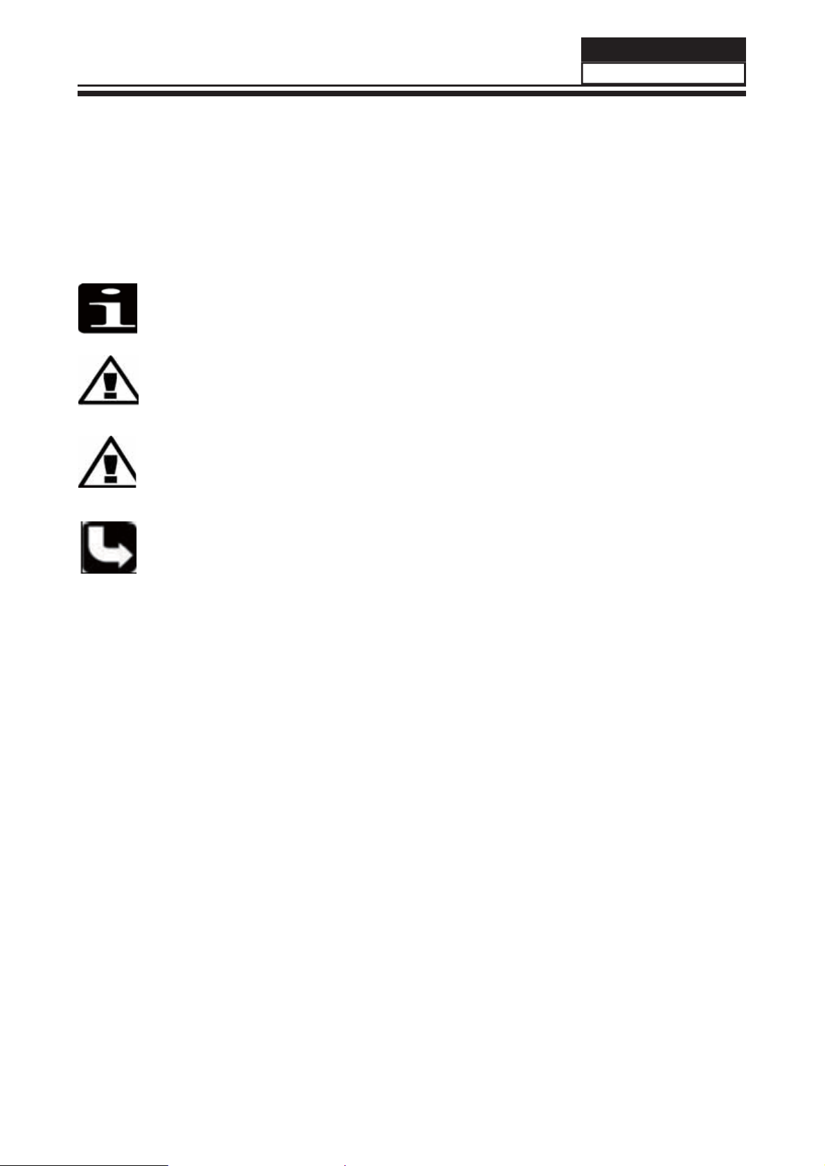
Note:
A “note” provides information that is not indispensable, but may nevertheless be
valuable to the reader, such as tips and tricks.
Caution:
A “caution” is used when there is danger that the reader, through incorrect
manipulation, may damage equipment, loose data, get an unexpected result or has to
restart(part of) a procedure.
Warning:
A “warning” is used when there is danger of personal injury.
used to attract the attention of the reader to specific information. The
Service Manual
HBTV-22D02FD
Reference:
A “reference” guides the reader to other places in this binder or in this manual,
where he/she will find additional information on a specific topic.
7
Page 9
Service Manual
HBTV-22D02FD
Chapter 2. Specifi cation
2-1. Specifi cation list
Model HBTV
Screen Size 22 inches
Aspect Ratio 16:9
Resolution 1920*1080
Response Time (ms) 5ms
Angel of View H:170/V:160
Color Display 16.7M
No. of Preset Channels 181
OSD Language English/Brazil Portuguese
Color System PAL/NTSC/ISDB-T
Audio System M/N
Audio Output Power (Built-in) (W) 3W*2
Audio Output Power (outer) (W) No
-22D02FD
Total Power Input (W) 35W
Voltage Range (V) AC100V~240V
Power Frequency (Hz) 50~60Hz
Time of Sleep Timer (MINS) 240Min
Net Weight (KG) 3.17
Gross Weight (KG) 3.75
Net Dimension (MM) 528/160/388
Packaged Dimension (MM) 620/120/445
8
Page 10
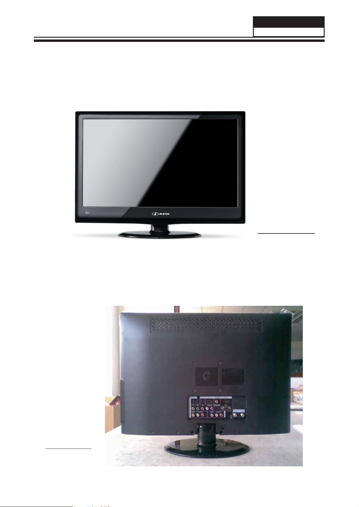
2-2. External pictures
Service Manual
HBTV-22D02FD
Front Side
Back Side
9
Page 11
Service Manual
HBTV-22D02FD
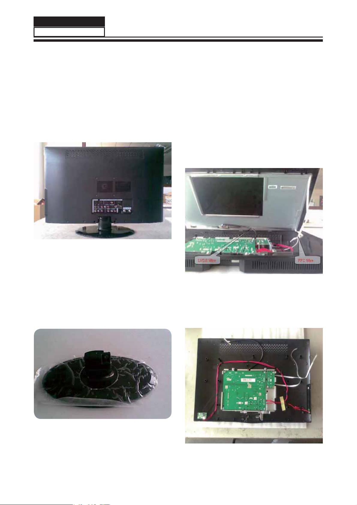
Chapter 3. Disassemble and Assemble
3-1. Remove the Stand
1.
Lay down the unit so that back cover faces
upward.
picture 1
3-2. Remove the Back Cover
1.
Remove the 2 and 3 screws indicated in
picture 1.
2.Uncover the equipment, the FFC wire and
LVDS wire are s h o w n b e l o w (See picture 3).
Remove the FFC wire and LVDS wire from
the panel.
2. Remove
which are indicated with the number in the
picture above.
3. Remove the stand (See picture 2).
the 1 screw from the back cover
picture 2
picture 3
3. Then remove the back cover from the unit.
(See picture 4).
picture 4
10
Page 12
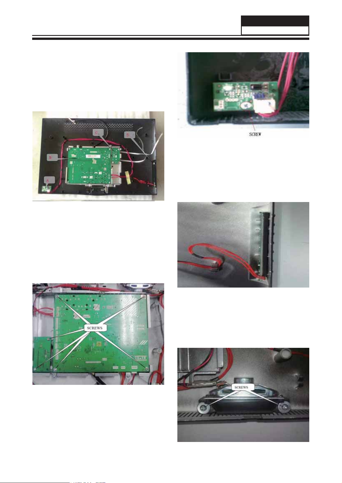
3-3. Remove the Main Board &
Small Board
There are four boards in the machine:
A:Remote Control Board;B:Main Board;C:LED
Driver Board ;D:Keypad Board (See picture 5).
Service Manual
HBTV-22D02FD
picture 7
3-3-3. Remove the Keypad Board
There's no screw in this board,pull the keypad
board out from Front Cabinet directly.
picture 5
3-3-1. Remove the Mainboard and the
Driver Board
Remove the six screws indicated in picture 6.
ake out the mainboard and the drive board.
T
picture 8
3-3-4. Remove the Speakers
Remove the two screws indicated in picture 9
Take out one speaker
,then another as this.
picture 6
3-3-2.Remove the Remote Control Board
Remove the screw indicated in picture 7.
Take out the mainboard and the drive board.
picture 9
11
Page 13
Service Manual
HBTV-22D02FD
Chapter 4. Location of Controls and Components
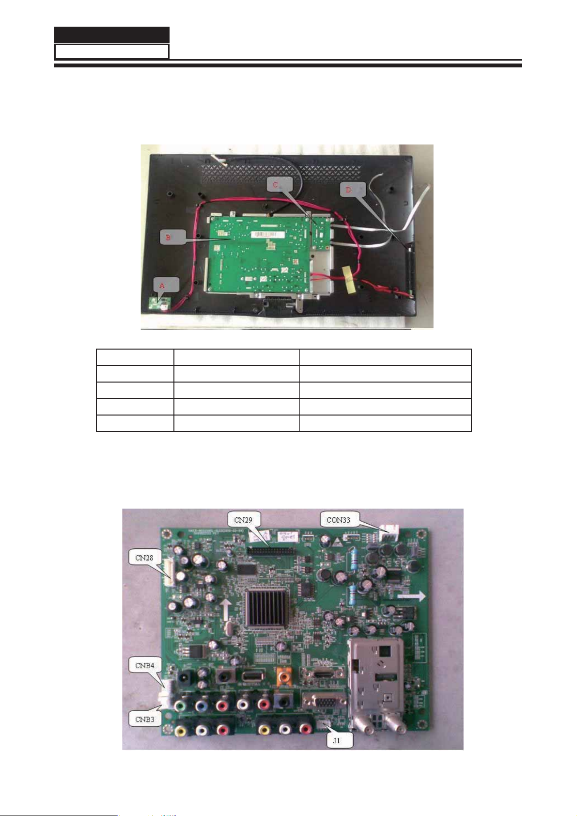
4-1. Board Location
No. Parts number Description
A Board
B Board
C Board
D Board
410262
497375
410254
410260
A PLACA PRINCIPAL SOMENTE PODE SER SOLICITADA
ATRAVÉS DO SUPORTE TÉCNICO !!!
4-2. Main Board (Placa Principal)
PCI Sensor Remoto
Placa Principal (V2)
PCI Inversora LCD
PCI do Teclado
12
Page 14

Service Manual
HBTV-22D02FD
4-2-1. Function Description:
Main Board
Process signal which incept from exterior equipment then translate into signal that panel can display
4-2-2. Connector defi nition
Main board connector
.
CNB4 CNB3
Pin number
1
Signal name Pin number Signal name
+5V
1
2 IR 2 KEY1
3 RED 3 KEY2
4 GREEN
5 GND
J1
Pin number Signal name
1
2
+5V
GND
3RX
4TX
CN28 CON33
Pin number
1
Signal name Pin number Signal name
PW_ON
1
2 GND 2 R3 GND 3 L4 ADJ 4 L+
5 PB-ON
6 +12V
7 +12V
Notes:
CNB4:Remote Control connector ; to
CNB3:Keypad connector ; to D Board
J1:Upgrade connector
CN28:Driver connector ; to C Board
CON33:Speaker connector ; to Speaker
CN29:LVDS connector ; to Panel
Board
A
GND
R+
CN29
Pin number Signal name
1
2
VDD
VDD
3 VDD
4 GND
5 GND
6 GND
7 RXO08 RXO0+
9 RXO1-
10 RXO1+
11 RXO212 RXO2+
13 GND
14 GND
15 RXOC16 RXOC+
17 RXO318 RXO3+
19 RXE020 RXE0+
21 RXE122 RXE1+
23 RXE224 RXE2+
25 GND
26 GND
27 RXEC28 RXEC+
29 RXE330 RXE3+
31 GND
32 GND
13
Page 15

Service Manual
HBTV-22D02FD
4-3. Driver Board
Connector defi nition:
CN1 Signal name
1
2 GND
3 GND
4 ADJ
5 PB-ON
6 +12V
7 +12V
PW_ON
4-4. Remote Control Board
4-5. LED Panel
Function description:T
Connector defi nition:
CN1 Signal name
1
2IR
3 RED
4 GREEN
5 GND
Function description:receive remote control
signal
o supply power for Panel.
+5V
14
Page 16

Chapter 5. Operation Instructions
5-1. Front Panel Controls
1
2
3
4
5
Service Manual
HBTV-22D02FD
PUT
IM
1. MENU :Menu display
2. INPUT
3. VOL(+/-) :V
:All input source display and OK con firm.
olume increase and decrease, menu set and entry
4. CH(+/-) :Program minus and plus, menu options
5. POWER :Is used to activate the display or return to standby mode.
5-2. BACK Panel Controls
5
6
1
2
7 8 9
DIGITAL
(COAXIAL)
OUT
HDMI IN
PC IN
10
4
3
IN
ANT
(AIR)
ANT IN
(CABLE)
11
COMPONEN T In
1
AV IN
2
PC IN
3
AV OUT V
4
DC IN
5
Connec t a com ponent Vide o/Audio device to
these jacks
Connec t Video/Au dio out from an Vide o/Audio
device to these jacks
Con
nect the mon itor out put conn ector f rom a PC
to the jack
ide o/A udio ou tput te rmin al
Connec t the monitor o utput co nnector from a D C
to the jack
Headphone Headphone audio output terminal.
6
Con
7
USB
DIGITAL
8
OUT(COAXIAL)
9
HDMI
0
PC/DVI AUDIO
1 1
ANT IN
nect a USB ash dr ive to vi ew PPEG2
videos,JPEG images or listen to MP3 songs.
Digital/Coaxial output terminal
Connec t a sig nal to H DMI
Connec t a PC/ DVI Audi o device to thes e jacks
Connec t a CA TV or AI R Antenn a cabIe
15
Page 17

Service Manual
HBTV-22D02FD
5-3. Remote Control
INPUT
1
2
MTS/S AP
CC
SLEEP
3
4
P.SIZE H. LOCK
FAVORIT E
5
USB
DNR
CH.LI ST
13
14
15
16
17
6
INFO
MUTE
7
8
VOL CH
MENU
9
Q.VI EW
18
19
Q.MENU
20
10
11
12
SOUND
ENTER
OK
ZOOM
21
PICTURE
22
GUIDE
23
EXIT
24
REPEAT
16
Page 18

e
clas do Controle Remoto
T
1. Input: Pressione para selecionar a fonte de sinal desejada.
2. CC: Pressione para habilitar ou desabilitar o closed caption.
Service Manual
HBTV-22D02FD
3. MTS/SAP: Pressione para alternar entre mono, estéreo e SAP
4. P
.Size: Pressione para alterar o tamanho da imagem.
5. H.Lock: Pressione para acessar o menu de bloqueios.
6. Teclado numérico: Utilize para selecionar o canal desejado.
7. Mute: Pressione para cortar temporariamente o som.
8. Teclas de volume: Pressione para aumentar ou diminuir o volume.
9. Menu: Pressione para acessar o menu principal.
10. Sound: Pressione para selecionar o modo pré-ajustado de áudio.
1 1 . T e c l a s c o l o r i d a s : Acionam ou acessam funções específicas nos menus.
12. Teclas de navegação USB: Utilize para navegar nos menus e arquivos no modo USB.
13. USB: Pressione para ter acesso direto a fonte de entrada USB.
14. Sleep: Pressione para selecionar em quanto tempo o televisor irá se desligar.
15. DNR: Pressione para habilitar ou desabilitar o redutor digital de ruídos.
16. CH.List: Pressione para acessar a lista de canais disponíveis.
17. Favorite: Pressione para acessar a lista de canais favoritos.
.
18. Q.View: Pressione para retornar ao último canal selecionado.
19. Teclas CH: Pressione para trocar de canal.
20. Q.Menu: Pressione para ter acesso ao menu rápido.
21. Teclas de navegação: Utilize para navegar pelos menus e funções do televisor.
22. Picture: Pressione para selecionar o modo pré-ajustado de imagem.
23. Guide: Pressione para ter acesso ao guia eletrônico de programação.
(apenas em TV digital).
24. Exit: Pressione para sair dos menus ou funções do televisor.
17
Page 19

Service Manual
HBTV-22D02FD
Chapter 6. Electrical Circuit
6-1. Power Tree
6-2. Wiring Connection Diagram
18
Page 20

Block Diagram
MT5363P1V1 (4 LAYERS)
UD3
DDR2
JC2
SD/MS SD/MS
UD2
DDR2
JL5
LVDS CONN
MTK5363
U1
PCI1
PCMCIA
SOCKET
SPDIF OUT
Audio DAC3
Audio DAC2
LINE IN
Tuner IF+/IF-
UA5
OPA
UA6
HP Driv
Line Out
HP OUT
PA3.PA4.PA7.PA8
LINE IN
UT1
TUNER
PA9
SPDIF OUT
U39
SPEAKER
AMP
P34
HP Out
JA1.JA2
SP
U4
NAND
Flash
U1.U3
Serial
Flash
NAND
SPI
USB
HDMI x1
UH19
HDMI SWITCH
HDMI1
HDMI2
HDMI3
PU1 PH3.PH4.PH5
USBx1
HDMIx3
RGB
VGA
YPbPr1
PV4
YPbPrx1
CVBS
RGB
SART1
CVBSx2
S-VIDEO
Audio DAC0
LINE IN
UA4
OPA
Line Out
Video DAC OUT1
SC
CVBS/SY
PV6PV5PV7
SART2
Audio DAC1
LINE IN
UA3
OPA
Line Out
Video DAC OUT2
01
10/01/11
Revisão
Formato
A3
Escala
S/E
PCI principal HBTV-22D02FD (MTK5363)
Data
Dimensão
mm
Documento
Elaborado por: Éber Silva
Liberação inicial
Descrição
Tol.não especificada
Página
1/17
PV1.PV2
CVBSx2
PV3
S-VIDEO
Revisado por: Eduardo Macedo
Código matriz
Código sistema
Aprovado por: Thomas Wang
Modificado por:
Page 21

6.3 - Circuit Diagram (Diagrama Elétrico)
MAIN POWER
5V_SW+5V
Note :
The power connected to RP4 should turn
UP8 off when +5V is turning on. Therefore,
If +5VSB lead +5V, please insert RP38.
If +5V lead +5VSB, please insert RP41.
STANDBY POWER 3V3SB
+5VSB
+
+
CEP7
CEP7
100uF/16V
100uF/16V
UP2 AP1117/adjUP2 AP1117/adj
3
IN
1
2
OUT
ADJ/GND
DIGITAL POWER DVDD3V3
UP5 AP1084/ADJUP5 AP1084/ADJ
+
+
CEP13
CEP13
100uF/16V
100uF/16V
3
IN
2
OUT
ADJ/GND
1
ANALOG POWER AVDD1V25
UP3 AP1117/adjUP3 AP1117/adj
2
OUT
IN
ADJ/GND
1
+
+
CEP9
CEP9
100uF/16V
100uF/16V
3
+
+
RP12
RP12
110_1%
110_1%
RP13
RP13
180_1%
180_1%
+
+
RP21
RP21
110_1%
110_1%
RP22
RP22
180_1%
180_1%
1.25 x (1+180/110) = 3.3V
+
+
RP15
RP15
110_1%/NC
110_1%/NC
RP160RP16
0
1.25 x (1+ 0/110) = 1.25V
DC+12V +5VSB
+
+
CE649
CE649
220uF/16V
220uF/16V
CEP8
CEP8
100uF/16V
100uF/16V
CEP14
CEP14
NS/100uF/16V
NS/100uF/16V
CEP10
CEP10
100uF/16V
100uF/16V
C13
C13
0.1uF
0.1uF
RP43 FBRP43 FB
LP20RLP2
CP3
CP3
10uF/10v
10uF/10v
3V3SB
AVDD3V3
DVDD3V35V_SW
AVDD1V25DVDD3V3
5V MAIN POWER
0R
C14
C14
0.1uF
0.1uF
R91
R91
100K
100K
CPU1
CPU1
MP1484
MP1484
3
VCC2OUT
7
EN
6
C20
C20
0.1uF
0.1uF
COMP
8
SS
4
GND
GND
9
+12V +5V
+
+
C5
10nFC510nF
R8
2.2KR82.2K
BST
FB
CEP2
CEP2
100uF/16v
100uF/16v
C21
C21
10nF
10nF
1
5
CPC31
CPC31
+
+
470uF/16V
470uF/16V
H2
H2
9
9
8
8
7
7
6
6
1
1
H4
H4
9
9
8
8
7
7
6
6
1
1
CORE POWER
+12V VCCK
LP30RLP3
0R
R89 100KR89 100K
C16
C16
CP4
CP4
NC/0.1uF
NC/0.1uF
10uF/10v
+
+
220uF/16v
220uF/16v
XC14
XC14
10uF/10v
C15
C15
0.1uF
0.1uF
C6
10nFC610nF
R12
R12
2.2K
2.2K
C22
C22
0.1uF
0.1uF
VCC2OUT
7
EN
6
COMP
8
SS
4
GND
U60
U60
MP1482
MP1482
+
+
C777
C777
47uF/16V
47uF/16V
CPR13 0RCPR13 0R
CPC40
CPC40
470uF/16V
470uF/16V
+
+
3
C23
C23
10nF
10nF
1
BST
5
FB
GND
9
L510uH/3A L510uH/3A
12
R6
R6
5.1K_1%
5.1K_1%
R0603
R0603
R11
R11
27K_1%
27K_1%
R0603
R0603
0.925 x (1+Rup/Rdn) = 1.1V
L3
L3
D3
B340/NCD3B340/NC
HOLE/GND/NC
HOLE/GND/NC
MTH157
MTH157
2
2
3
3
4
4
5
5
HOLE/GND/NC
HOLE/GND/NC
MTH157
MTH157
2
2
3
3
4
4
5
5
CPC42
CPC42
1uF
1uF
CPC39
CPC39
0.1uF
0.1uF
10uH/3A
10uH/3A
CPC43
CPC43
2A
0.01uF
0.01uF
OPWRSB
BL_ON/OFF#
Dimming
BL_DIMMING
+5VSB
+12V
+5V
3V3SB
DVDD3V3
AVDD3V3
AVDD1V25
VCCK
MAIN POWER
J4
J4
NC
NC
Jack_DCIN
Jack_DCIN
HI = > STANDBY
LO = > POWER_ON
OPWRSB
1
3
2
MAIN POWER
XR9
XR9
4.7K
4.7K
XR11
XR11
47K
47K
RV14
RV14
ESD_0402_10pF
ESD_0402_10pF
+5VSB
XR41KXR4
1K
XQ1
XQ1
1
2N3904
2N3904
2 3
DC+12V
SW_POWER
C8
0.1uFC80.1uF
R1619=1M CB991=1uF
to reduce current of 12V <6A.
2010.09.02
R1619 10K->1MR1619 10K->1M
U50
DC+12V +12V
10k
10k
R1618
R1618
R1617
R1617
4.7K
4.7K
Q44
Q44
1
2N3904
2N3904
CB991
CB991
2 3
0.1uF->1uF
0.1uF->1uF
U50
1
2
3
4 5
ME9435
ME9435
8
7
6
CB990
CB990
0.1uF
0.1uF
+5VSB16
+12V10,12,14,17
+5V7,10,14, 15,17
3V3SB6,15,17
DVDD3V34,5,6,7,10,12,15,17
AVDD3V37,9,17
BL_ON/OFF#17
Dimming17
BL_DIMMING8,17
8
7
6
OIRI
LED_RED#
12
D7
D7
ESD_0402_10pF
ESD_0402_10pF
LED_GRE#
LED_GRE#
12
D8
D8
ESD_0402_10pF
ESD_0402_10pF
AVDD1V254,5,7,9,17
OPWRSB6
OPCTRL0
VCCK4
GND4,5,6,7,9,10,11,12,13,14,15,16,17,18
+5V
CB989
CB989
0.1uF
0.1uF
OIRI
L5_9
L5_9
12
R4
R4
12K_1%
12K_1%
R0603
R0603
R7
R7
2.7K_1%
2.7K_1%
R0603
R0603
CEP1
CEP1
+
+
100uF/16V
100uF/16V
CPC28
CPC28
1uF
1uF
CPC29
CPC29
0.1uF
0.1uF
CPC30
CPC30
10nF
10nF
Other Control Interface
0.925 x (1+Rup/Rdn) = 5.04V
U49
R1774 100R1774 100
OPCTRL06
R661kR66
1k
23
2N3906
2N3906
Q51
Q51
+5VSB
R17771kR1777
1k
Q67
Q67
2N3904
2N3904
2 3
U49
1
2
3
4 5
ME9435
ME9435
6 OIRI
+5VSB
R1621
R1621
10k
10k
R16231KR1623
1K
VCCK
R1622 10KR1622 10K
CB992
CB992
0.1uF
0.1uF
Q46
Q46
1
2N3904
2N3904
2 3
IR Receiver & LED
3V3SB
R13
R1775
R1775
10k
10k
R1776 4.7KR1776 4.7K
R1778 4.7KR1778 4.7K
R13
NC/4.7K
NC/4.7K
12
D2
D2
ESD_0402_10pF
ESD_0402_10pF
1
1
+5VSB
CNE1
CNE1
1
IR_IN
2
HOLE/GND/NC
HOLE/GND/NC
H1
H1
MTH157
MTH157
H3
H3
1
1
HOLE/GND/NC
HOLE/GND/NC
MTH157
MTH157
1
1
2
2
3
3
4
4
5
5
2
2
3
3
4
4
5
5
TJC2004-5AW
TJC2004-5AW
9
9
8
8
7
7
6
6
9
9
8
8
7
7
6
6
3
4
5
OPCTRL0
HI = > LED RED
LO=> LED GREEN
LED_RED#
LED_GRE#
T7T7
C806
C806
NC/47pF_25v
NC/47pF_25v
C0402
C0402
+5VSB +5VSB
01
Revisão
Formato
10/01/11
Data
Documento
Elaborado por: Éber Silva
Liberação inicial
Descrição
A3
Escala
S/E
Dimensão
mm
Tol.não especificada
PCI principal HBTV-22D02FD (MTK5363)
Revisado por: Eduardo Macedo
Página
Código matriz
2/17
Código sistema
Aprovado por: Thomas Wang
Modificado por:
Page 22

VCCK and Digital I/O Bypass
UM1A
UM1A
P15
DVSS
W16
DVSS
U16
DVSS
AB15
DVSS
V15
DVSS
T15
DVSS
R14
DVSS
AC14
DVSS
W14
DVSS
AD13
DVSS
N14
DVSS
G10
DVSS
AB13
DVSS
U20
DVSS
AF9
DVSS
F9
DVSS
D9
DVSS
AE8
DVSS
G8
DVSS
E8
DVSS
C8
DVSS
W6
DVSS
L6
DVSS
J6
DVSS
W4
DVSS
L4
DVSS
J4
DVSS
Y3
DVSS
AB21
DVSS
Y21
DVSS
V21
DVSS
T21
DVSS
P21
DVSS
D21
DVSS
B21
DVSS
AC20
DVSS
AA20
DVSS
W20
DVSS
R20
DVSS
AB19
DVSS
N20
DVSS
AB17
DVSS
Y19
DVSS
V19
DVSS
T19
DVSS
AC18
DVSS
AA18
DVSS
W18
DVSS
U18
DVSS
R18
DVSS
AA16
DVSS
Y17
DVSS
V17
DVSS
T17
DVSS
AC16
DVSS
AC22
DVSS
AA22
DVSS
W22
DVSS
U22
DVSS
R22
DVSS
G22
DVSS
E22
DVSS
AD21
DVSS
P23
DVSS
T23
DVSS
V23
DVSS
Y23
DVSS
AB23
DVSS
AD23
DVSS
R24
DVSS
U24
DVSS
MT5363_SMD BGA-518_0108
MT5363_SMD BGA-518_0108
Strapping Mode
ICE Mode + Serial Boot
ICE mode + ROM Boot
VCCIO33
VCCIO33
VCCIO33
VCCIO33
VCCIO33
VCCIO33
VCCIO33
VCCIO33
VCCIO33
VCCK
VCCK
VCCK
VCCK
VCCK
VCCK
VCCK
VCCK
VCCK
VCCK
VCCK
VCCK
VCCK
VCCK
VCCK
VCCK
VCCK
VCCK
VCCK
VCCK
VCCK
VCCK
VCCK
VCCK
VCCK
VCCK
VCCK
VCCK
VCCK
VCCK
VCCK
VCCK
VCCK
VCCK
VCCK
VCCK
VCCK
VCCK
DVSS
DVSS
DVSS
DVSS
AG30
AH33
AG32
AF29
AH29
AH31
AF13
W36
W34
W32
V31
H31
J30
H23
AF15
AD15
V25
T25
AA24
N24
AE22
R16
AD17
AD19
AE18
AE20
AE16
N22
W24
Y15
AE14
AA14
U14
Y13
V13
AG12
AL8
AJ8
AM7
AK7
AH7
AL6
AJ6
AM5
AK5
AN4
AL4
AM3
AN2
AL2
AM1
Y25
AB25
AD25
P25
AE24
AC24
Power
Power
&
&
Ground
Ground
AVDD12_APLL
AVDD12_ADCPLL
AVDD12_SYSPLL
AVDD12_TVDPLL
AVSS12_PLL
AVSS12_PLL
AOLRCK AOBCK ASPDIF
0 0 0
0
0 1
AVDD1V25_PLL
CM1
VCCK
VCCK
CM8
CM8
0.1uF
0.1uF
CM1
0.1uF
0.1uF
DVDD3V3IO
CM3
CM3
0.1uF
0.1uF
CM9
CM9
0.1uF
0.1uF
CM2
CM2
0.1uF
0.1uF
CM4
CM4
0.1uF
0.1uF
CM10
CM10
0.1uF
0.1uF
MT5363 STRAPPING MODE
RM106 0RM106 0
Bottom Side
CM6
CM11
CM11
0.1uF
0.1uF
CM6
0.1uF
0.1uF
CM5
CM5
0.1uF
0.1uF
M_AOLRCK
M_AOBCK
AVDD1V25
CM7
CM7
0.1uF
0.1uF
CM12
CM12
0.1uF
0.1uF
RM105 4.7KRM105 4.7K
RM107 4.7KRM107 4.7K
DVDD3V3
Bottom Side
CM14
CM13
CM13
0.1uF
0.1uF
CM14
0.1uF
0.1uF
CM15
CM15
0.1uF
0.1uF
POWER TREE
+5V
AX1084MA
CM16
CM16
0.1uF
0.1uF
MOS
UP5
SOT223
Enable by VCCK5V_SW
DVDD3V3
AVDD3V3
DEMO3V3
UP4
AX1117SJ
SOT223
UP3
AX1117SJ
SOT223
HW Strap Setting
UP6 VCCK
AX4101
SOP-8
DDRV
1/2
AVDD1V25
UP4
AX1117SJ
SOT223
(OPTION)
+5VSB3,16
+12V3,10,12,14,17
+5V3,7,10,14,15,17
3V3SB3,6,15,17
DVDD3V33,5,6,7,10,12,15,17
AVDD3V33,7,9,17
AVDD1V253,5,7,9,17
VCCK3
GND3,5,6,7,9,10,11,12,13,14,15,16,17,18
M_AOLRCK9
M_AOBCK9
M_AOSDATA09
M_SPDIF_Out9,10
M_OPWM18
M_OPCTRL36,15,16
MEM_VREF
AVDD3V3
+5VSB
+12V
+5V
3V3SB
DVDD3V3
AVDD3V3
AVDD1V25
VCCK
M_AOLRCK
M_AOBCK
M_AOSDATA0
M_SPDIF_Out
M_OPWM1
M_OPCTRL3
Strapping Mode OPWM1AOSDATA0
XTAL 54MHz
1 0
Strapping Mode OPCTRL3(O)
PDWNC Normal
0
DVDD3V3
RM110 4.7KRM110 4.7K
M_SPDIF_Out
M_AOSDATA0
M_OPWM1
M_OPCTRL3
RM109 4.7KRM109 4.7K
RM113 4.7KRM113 4.7K
RM115 4.7KRM115 4.7K
UT5
+12V +5V_Tuner
G9085TU3U
TO-263-3
(OPTION)
01
Revisão
Formato
10/01/11
Data
Documento
Elaborado por: Éber Silva
Liberação inicial
Descrição
A3
Escala
S/E
Dimensão
mm
Tol.não especificada
PCI principal HBTV-22D02FD (MTK5363)
+5VSB +3V3SB
Revisado por: Eduardo Macedo
Página
Código matriz
3/17
Código sistema
UP2
G1117
SOT223
UP1
G969
MSOP8
(OPTION)
Aprovado por: Thomas Wang
1V0SB
Modificado por:
Page 23

DDR2 Interface
DDRV
AV1V25_MEMPLL
RVREF3
RCKE
RCLK0
RCLK0#
RCLK1
RCLK1#
RODT
RRAS#
RCAS#
RCS#
RWE#
RM1 100RM1 100
RBA0
RBA1
RBA2
G14
AF3
AE4
B13
AD7
E14
D13
AE2
C12
E12
AC6
F13
AD5
AF1
P13
T13
AD1
AD3
AB5
J14
UM1B
UM1B
C2
VCC2IO
VCC2IO
B1
VCC2IO
VCC2IO
R2
VCC2IO
R4
VCC2IO
E4
VCC2IO
G6
VCC2IO
VCC2IO
H7
VCC2IO
R6
VCC2IO
VCC2IO
VCC2IO
VCC2IO
VCC2IO
VCC2IO
F5
VCC2IO
VCC2IO
VCC2IO
VCC2IO
VCC2IO
D3
VCC2IO
VCC2IO
VCC2IO
VCC2IO
AVDD12_MEMPLL
AVSS12_MEMPLL
K5
MEMTN
K7
MEMTP
P7
RVREF
N8
RVREF
K1
RCKE
B3
RCLK0
A2
RCLK0#
RCLK1
RCLK1#
N6
RODT
P5
RRAS#
L2
RCAS#
P3
RCS#
K3
RWE#
REXTDN
H3
RBA0
J2
RBA1
H1
RBA2
MT5363_SMD BGA-518_0108
MT5363_SMD BGA-518_0108
DRAM
DRAM
RDQM0
RDQS0
RDQS0#
RDQ0
RDQ1
RDQ2
RDQ3
RDQ4
RDQ5
RDQ6
RDQ7
RDQM1
RDQS1
RDQS1#
RDQ8
RDQ9
RDQ10
RDQ11
RDQ12
RDQ13
RDQ14
RDQ15
RDQM2
RDQS2
RDQS2#
RDQ16
RDQ17
RDQ18
RDQ19
RDQ20
RDQ21
RDQ22
RDQ23
RDQM3
RDQS3
RDQS3#
RDQ24
RDQ25
RDQ26
RDQ27
RDQ28
RDQ29
RDQ30
RDQ31
RA0
RA1
RA2
RA3
RA4
RA5
RA6
RA7
RA8
RA9
RA10
RA11
RA12
RA13
E10
B9
A8
D7
H11
E6
G12
H13
D5
F11
F7
C10
B7
C6
B5
D11
A4
B11
A12
C4
A10
A6
V1
V3
W2
AB1
U4
AC4
T1
T3
AC2
U2
AB3
U6
Y1
AA2
Y5
T7
AA6
V7
V5
AA4
T5
Y7
N4
H5
M3
G4
M5
F1
M7
F3
P1
D1
G2
N2
E2
M1
RDQM0
RDQS0
RDQS0#
RDQ0
RDQ1
RDQ2
RDQ3
RDQ4
RDQ5
RDQ6
RDQ7
RDQM1
RDQS1
RDQS1#
RDQ8
RDQ9
RDQ10
RDQ11
RDQ12
RDQ13
RDQ14
RDQ15
RDQM2
RDQS2
RDQS2#
RDQ16
RDQ17
RDQ18
RDQ19
RDQ20
RDQ21
RDQ22
RDQ23
RDQM3
RDQS3
RDQS3#
RDQ24
RDQ25
RDQ26
RDQ27
RDQ28
RDQ29
RDQ30
RDQ31
RA0
RA1
RA2
RA3
RA4
RA5
RA6
RA7
RA8
RA9
RA10
RA11
RA12
RA13
DRAM DE-CAP.
DDRV
+
+
CED4
CED4
47uF/16V/NC
47uF/16V/NC
[ RESERVE ]
DDRV
+
+
CED5
CED5
47uF/16V/NC
47uF/16V/NC
[ RESERVE ]
MT5363 DE-CAP.
DDRV
+
+
CEM1
CEM1
NC/47uF/10V
NC/47uF/10V
DRAM POWER DDRV
+
+
CED1
CED1
100uF/16V
100uF/16V
CD29
CD26
CD26
NS/0.1uF
NS/0.1uF
CM19
CM19
NS/0.1uF
NS/0.1uF
[ RESERVE ] [ RESERVE ]
CD12
CD12
1uF
1uF
CD29
NS/0.1uF
NS/0.1uF
[ RESERVE ][ RESERVE ]
CD30
CD30
NS/0.1uF
NS/0.1uF
CD22
CD22
1uF
1uF
UD1 AP1084/ADJUD1 AP1084/ADJ
3
IN
OUT
ADJ/GND
1
CD23
CD23
0.1uF
0.1uF
CM17
CM17
0.1uF
0.1uF
CD13
CD13
0.1uF
0.1uF
CD24
CD24
0.1uF
0.1uF
CM18
CM18
0.1uF
0.1uF
CD14
CD14
0.1uF
0.1uF
2
+
RD1
RD1
280_1%
280_1%
RD2
RD2
121_1%
121_1%
+
CED2
CED2
100uF/16V
100uF/16V
1.25 x (1+121/280) = 1.8V for DDR2
CD25
CD25
0.1uF
0.1uF
CM20
CM20
0.1uF
0.1uF
CD15
CD15
0.1uF
0.1uF
DDR#1 Bottom Side
CD27
CD27
0.1uF
0.1uF
CD28
CD28
0.1uF
0.1uF
DDR#2 Bottom Side
CM21
CM21
0.1uF
0.1uF
CM22
CM22
0.1uF
0.1uF
Main Chip Bottom Side
CD17
CD16
CD16
0.1uF
0.1uF
CD17
0.1uF
0.1uF
CD2
CD2
1uF
1uF
DDRVDVDD3V3
[ RESERVE ]
CD20
CD20
0.1uF
0.1uF
CM23
CM23
0.1uF
0.1uF
CD19
CD19
0.1uF
0.1uF
CD3
CD3
NS/0.1uF
NS/0.1uF
+5VSB3,16
+12V3,10,12,14,17
+5V3,7,10,14,15,17
3V3SB3,6,15,17
DVDD3V33,4,6,7,10,12,15,17
AVDD3V33,7,9,17
AVDD1V253,4,7,9,17
VCCK3,4
GND3,4,6,7,9,10,11,12,13,14,15,16,17,18
+5VSB
+12V
+5V
3V3SB
DVDD3V3
AVDD3V3
AVDD1V25
VCCK
UD3
UD3
RDQ16
RDQ17
RDQ18
RDQ19
RDQ20
RDQ21
RDQ22
RDQ23
RDQ24
RDQ25
RDQ26
RDQ27
RDQ28
RDQ29
RDQ30
RDQ31
RDQS3
RDQS3#
RDQS2
RDQS2#
RDQM3
RDQM2
RVREF2 2_RAS#
2_CKE
DDRV DDRV
G8
DQ0
G2
DQ1
H7
DQ2
H3
DQ3
H1
DQ4
H9
DQ5
F1
DQ6
F9
DQ7
C8
DQ8
C2
DQ9
D7
DQ10
D3
DQ11
D1
DQ12
D9
DQ13
B1
DQ14
B9
DQ15
A2
NC
E2
NC
B7
UDQS
A8
UDQS
F7
LDQS
E8
LDQS
B3
UDM
F3
LDM
J2
VREF
K2
CKE
A1
VDD
A9
VDDQ
C1
VDDQ
C3
VDDQ
C7
VDDQ
C9
VDDQ
E1
VDD
E9
VDDQ
G1
VDDQ
G3
VDDQ
G7
VDDQ
G9
VDDQ
J1
VDDL
J9
VDD
M9
VDD
R1
VDD
NT5TU32M16CG-BD
NT5TU32M16CG-BD
DDR#2
A10/AP
NC/A13
NC/A14
NC/N15
BA0
BA1
NC/BA2
CAS
ODT
RAS
VSS
VSSQ
VSSQ
VSSQ
VSSQ
VSSQ
VSS
VSSQ
VSSQ
VSSQ
VSSQ
VSSQ
VSS
VSSDL
VSS
VSS
A11
A12
WE
A0
A1
A2
A3
A4
A5
A6
A7
A8
A9
CK
CK
CS
2_A0
M8
2_A1
M3
2_A2
M7
2_A3
N2
2_A4
N8
2_A5
N3
2_A6
N7
2_A7
P2
2_A8
P8
2_A9
P3
2_A10
M2
2_A11
P7
2_A12
R2
2_A13
R8
R3
R7
2_BA0
L2
2_BA1
L3
2_BA2
L1
CLK1
J8
CLK1#
K8
2_CS#
L8
2_CAS#
L7
2_ODT
K9
K7
2_WE#
K3
A3
A7
B2
B8
D2
D8
E3
E7
F2
F8
H2
H8
J3
J7
N1
P9
Damping for DDR#2 ADDR/CMD
NEAR BRANCH
RND6 56x4RND6 56x4
2_A0
2_A13
2_A8
2_A3
2_A10
2_A1
2_BA2
2_BA0
2_BA1
2_CKE
2_WE#
2_A11 RA11
2_A6 RA6
2_A2 RA2
2_A9
2_A12
2_A7
2_A5 RA5
RRAS#
RODT
1 2
3 4
5 6
7 8
RND7 56x4RND7 56x4
1 2
3 4
5 6
7 8
RND8 56x4RND8 56x4
1 2
3 4
5 6
7 8
RND9 56x4RND9 56x4
1 2
3 4
5 6
7 8
RND10 56x4RN D10 56x4
1 2
3 4
5 6
7 8
RCAS#2_CAS#
RA0
RA13
RA8
RA3
RA10
RA1
RBA2
RBA0
RBA1
RCKE
RWE#
RA42_A4
RA9
RA12
RA7
2_CS#RCS#
78
2_RAS#
56
2_ODT
34
12
RND1256x4 RND1256x4
Damping and Termination for CLK
NEAR DRAMNEAR IC
RCLK1
RD12 22RD12 22
RD14 22RD14 22
CLK1
RD13
RD13
100
100
CLK1#RCLK1#
Damping for DDR#1 ADDR/CMD
NEAR BRANCH
1_A8
RND1 56x4RND1 56x4
1_A13
1_A0
1_A12 RA12
1_A7
1_A5
1_A2
1_A6
1_A4
1_A11
1_BA2
1_A1
1_A10
1_A3
1_WE#
1_CKE
1_BA1
1_BA0
RODT 1_OD T
RRAS# 1_RAS#
RCS# 1_CS#
1 2
3 4
5 6
7 8
RND2 56x4RND2 56x4
1 2
3 4
5 6
7 8
RND3 56x4RND3 56x4
1 2
3 4
5 6
7 8
RND4 56x4RND4 56x4
RND5 56x4RND5 56x4
RND11 56x4RN D11 56x4
1 2
3 4
5 6
7 8
RA8
RA13
RA0
RCAS#1_CAS#
RA91_A9
RA7
RA5
RA2
RA6
RA4
RA11
RBA2
12
RA1
34
RA10
56
RA3
78
RWE#
12
RCKE
34
RBA1
56
RBA0
78
Damping and Termination for CLK
NEAR DRAMNEAR IC
RCLK0
RD6 22RD6 22
RD8 22RD8 22
CLK0
RD7
RD7
100
100
CLK0#RCLK0#
RDQ0
RDQ1
RDQ2
RDQ3
RDQ4
RDQ5
RDQ6
RDQ7
RDQ8
RDQ9
RDQ10
RDQ11
RDQ12
RDQ13
RDQ14
RDQ15
RDQS1
RDQS1#
RDQS0
RDQS0#
RDQM1
RDQM0
RVREF1
1_CKE
UD2
UD2
G8
DQ0
G2
DQ1
H7
DQ2
H3
DQ3
H1
DQ4
H9
DQ5
F1
DQ6
F9
DQ7
C8
DQ8
C2
DQ9
D7
DQ10
D3
DQ11
D1
DQ12
D9
DQ13
B1
DQ14
B9
DQ15
A2
NC
E2
NC
B7
UDQS
A8
UDQS
F7
LDQS
E8
LDQS
B3
UDM
F3
LDM
J2
VREF
K2
CKE
A1
VDD
A9
VDDQ
C1
VDDQ
C3
VDDQ
C7
VDDQ
C9
VDDQ
E1
VDD
E9
VDDQ
G1
VDDQ
G3
VDDQ
G7
VDDQ
G9
VDDQ
J1
VDDL
J9
VDD
M9
VDD
R1
VDD
NT5TU32M16CG-BD
NT5TU32M16CG-BD
DDR#1
A10/AP
A11
A12
NC/A13
NC/A14
NC/N15
BA0
BA1
NC/BA2
CAS
ODT
RAS
VSS
VSSQ
VSSQ
VSSQ
VSSQ
VSSQ
VSS
VSSQ
VSSQ
VSSQ
VSSQ
VSSQ
VSS
VSSDL
VSS
VSS
RVREF_as closed to UD2
1_A0
M8
A0
A1
A2
A3
A4
A5
A6
A7
A8
A9
CK
CK
CS
WE
1_A1
M3
1_A2
M7
1_A3
N2
1_A4
N8
1_A5
N3
1_A6
N7
1_A7
P2
1_A8
P8
1_A9
P3
1_A10
M2
1_A11
P7
1_A12
R2
1_A13
R8
R3
R7
1_BA0
L2
1_BA1
L3
1_BA2
L1
CLK0
J8
CLK0#
K8
1_CS#
L8
1_CAS#
L7
1_ODT
K9
1_RAS#
K7
1_WE#
K3
A3
A7
B2
B8
D2
D8
E3
E7
F2
F8
H2
H8
J3
J7
N1
P9
DDRV
RD15 1K_1%RD 15 1K_1%
RD16
RD16
1K_1%
1K_1%
AV1V25_MEMPLL
AVDD1V25
AV1V25_MEMPLL
2009/04/15
01
10/01/11
Revisão
Formato
Data
Elaborado por: Éber Silva
RVREF1
Documento
CD6
CD6
0.1uF
0.1uF
CD10
CD10
0.01uF
0.01uF
RVREF_as closed to UD3
DDRV
RD17 1K_1%RD 17 1K_1%
RVREF2
RD18
RD18
1K_1%
1K_1%
RVREF_as closed to MT5363
DDRV
RD19 1K_1%RD 19 1K_1%RD21 0RD21 0
Liberação inicial
Descrição
Revisado por: Eduardo Macedo
RVREF3
RD20
RD20
1K_1%
1K_1%
CD7
CD7
0.1uF
0.1uF
CD5
CD5
0.1uF
0.1uF
Aprovado por: Thomas Wang
Modificado por:
A3
Escala
S/E
Dimensão
mm
Tol.não especificada
Página
4/17
Código matriz
Código sistema
PCI principal HBTV-22D02FD (MTK5363)
Page 24

AVDD3V3_REG
1V0SB
AVDD3V3_XTAL
E_FUSE
OIRI
OPCTRL0
USB_PWR_EN0
USB_PWR_OCP
M_OPCTRL3
PAALE
PACLE
PARB#
POWE#
POCE0#
POCE1#
POOE#
PDD0
PDD1
PDD2
PDD3
PDD4
PDD5
PDD6
PDD7
Amp_MUTE9
Amp_MUTE
UM1C
UM1C
AN24
AVDD33_VGA_STB
AL24
AVSS33_VGA_STB
AM23
AVDD10_LDO
AK35
AVDD33_XTAL_STB
AK37
AVSS33_XTAL
L30
FSRC_WR
AN22
OIRI
AM21
OPCTRL0
AM19
OPCTRL1
AN20
OPCTRL2
AR20
OPCTRL3
AU20
OPCTRL4
AR4
PAALE
AU4
PACLE
AT5
PARB#
AT3
POWE#
AT1
POCE0#
AN6
POCE1#
AU2
POOE#
AR2
PDD0
AP5
PDD1
AR6
PDD2
AU6
PDD3
AP7
PDD4
AT7
PDD5
AR8
PDD6
AU8
PDD7
MT5363_SMD BGA-518_0108
MT5363_SMD BGA-518_0108
Amp_MUTE
STB I/F &
STB I/F &
Peripheral
Peripheral
ORESET#
OPWRSB
XTALO
XTALI
VCXO
ADIN5_SRV
ADIN4_SRV
ADIN3_SRV
ADIN2_SRV
ADIN1_SRV
ADIN0_SRV
U0RX
U0TX
U1RX
U1TX
JTDO
JTMS
JTCK
JTDI
JTRST#
OSCL2
OSDA2
OSCL1
OSDA1
OSCL0
OSDA0
AL22
AL20
AJ34
AJ36
T37
AL36
AM37
AL34
AM35
AK33
AL32
AT21
AP21
R36
T35
AH5
AJ4
AK3
AJ2
AK1
P31
P33
R34
R32
AP3
AP1
ORESET#
OPWRSB
OXTALO
OXTALI
R124 4.7KR124 4.7K
R125 4.7KR125 4.7K
R126 4.7KR126 4.7K
ADIN2
ADIN1
ADIN0
U0RX
U0TX
U1RX
U1TX
JTDO
JTMS
JTCK
JTDI
JTRST#
SYS_EEPROM_WP
HP_DET#
OSCL0
OSDA0
TP72TP72
TP71TP71
3V3SB
3V3SB
1V0SB
JTRST#
RM165 0RM165 0
RM166 0RM166 0
R94 10KR94 10K
NEAR IC
AVDD3V3_REG
NEAR IC
AVDD3V3_XTAL
1V0SB
RM2 1RM2 1
CM26
CM26
0.1uF
0.1uF
CM28
CM28
0.1uF
0.1uF
CM29
CM29
4.7uF/10V
4.7uF/10V
RESET Circuit
3V3SB 3V3SB 3V3SB
R74
R73
R73
12K
12K
R76
R76
3.9K
3.9K
R74
10K
10K
1
Q2
1
2N3904Q22N3904
2 3
2 3
R75
R75
7.5K
7.5K
Q1
2N3904Q12N3904
+
+
CE21
CE21
47uF/16V
47uF/16V
ORESET#
CM31
CM31
0.1uF
0.1uF
+5VSB3,16
+12V3,10,12,14,17
+5V3,7,10,14,15,17
3V3SB3,15,17
DVDD3V33,4,5,7,10,12,15,17
AVDD3V33,7,9,17
AVDD1V253,4,5,7,9,17
VCCK3,4
GND3,4,5,7,9,10,11,12,13,14,15,16,17,18
Audio Mute/Digital Amp Control
HP_DET#
OPCTRL03
OSCL0
OSDA0
OSCL0
OSDA0
Other Control Interface
OPWRSB3
USB_PWR_EN07
USB_PWR_OCP7
M_OPCTRL34,15,16
OPCTRL0
USB_PWR_EN0
HP_DET#
OPWRSB
USB_PWR_OCP
M_OPCTRL3
HDMI SW CTRL
+5VSB
+12V
+5V
3V3SB
DVDD3V3
AVDD3V3
AVDD1V25
VCCK
NAND Flash
R68
R68
330
330
PARB#
POOE#
POCE1#
PACLE
PAALE
POWE#
Flash_WP#
R99
R99
POCE1# POCE0#
4.7K
4.7K
SYSTEM EEPROM
SYS_EEPROM_WP
HI = > WP
Lo = > WRITE
R88 0R88 0
JTAG Port
U2
U2
7
R/B
8
RE
9
CE
16
CLE
17
ALE
18
WE
19
WP
6
GND
13
VSS
36
VSS
NS/K9F5608U0M
NS/K9F5608U0M
Default 1GB
VCC
VCC
I/O7
I/O6
I/O5
I/O4
I/O3
I/O2
I/O1
I/O0
R77
R77
4.7K
4.7K
12
37
44
43
42
41
32
31
30
29
PDD7
PDD6
PDD5
PDD4
PDD3
PDD2
PDD1
PDD0
R78
R78
4.7K
4.7K
DVDD3V3
POCE0#
POCE0#
PDD0
Flash_WP#
DVDD3V3DVDD3V3
Serial Flash ( Co-Layout )
Default 8MB
U1
U1
1
R98
R98
4.7K
4.7K
R79
R79
4.7K
4.7K
OSCL0
OSDA0
HOLD#
2
VCC
3
NC
4
PO2
5
PO1
6
PO0
7
CS#
SO/PO78WP#/ACC
EON25B64
EON25B64
DVDD3V3DVDD 3V3DVDD3V3DVDD3V3
8
7
6
5
SCLK
SI
PO6
PO5
PO4
PO3
GND
U4
U4
NC
VCC
NC
WP
NC
SCL
GND
SDA
M24C32-W
M24C32-W
I2C ADDRESS "A0"
16
15
14
13
12
11
10
9
DVDD3V3
1
2
3
4
POOE#
PDD1
POOE#
PDD1
Flash_WP#PDD0
54MHz CRYSTAL
DVDD3V3DVDD3V3DVDD3V3DVDD3V3
R69
R69
4.7K
4.7K
OXTALI OXTALO
Y1 54MHzY1 54MHz
C17
C17
10pF
10pF
C18
C18
10pF
10pF
L1
820nHL1820nH
C19
C19
1nF
1nF
HW Strap Pins
ADIN2
M_OPCTRL34,15,16
ADIN2
M_OPCTRL3
KEY PANEL
CNE2
CNE2
1
UART Port 0
UART Port 1
IR Receiver
3V3SB 3V3SB 3V3SB
R83
R83
R82
R82
4.7K
4.7K
4.7K
4.7K
U0RX
U0TX
FOR CODE DOWNLOAD AND DEBUGGING
DVDD3V3 DVDD3V3 DVDD3V3
R84
R84
R85
R85
4.7K
4.7K
4.7K
4.7K
U1RX
U1TX
1
2
3
4
4x1 W/HOUSING
4x1 W/HOUSING
1
2
3
4
4x1 W/HOUSING/NC
4x1 W/HOUSING/NC
T8T8
TJC2004-3AW
TJC2004-3AW
J1
J1
3V3SB
J2
J2
U0RX16
U0TX16
E-Fuse
2
3
R1770 15KR1770 15K
R1772 15KR1772 15K
K0
K1
C629
C629
0.1uF
0.1uF
E_FUSE
C628
C628
0.1uF
0.1uF
U0RX
U0TX
R109 4.7KR109 4.7K
R1771 1.5KR1771 1.5K
R1773 1.5KR1773 1.5K
12
K0ADIN0
K1ADIN1
12
D4
D4
D5
D5
ESD_0402_10pF
ESD_0402_10pF
ESD_0402_10pF
ESD_0402_10pF
JTRST#
JTDI
JTMS
JTCK
JTDO
R93 33R93 33
R81
R81
10K
10K
R86
R86
10K
10K
R116
R116
10K
10K
R123
R123
10K
10K
TP17TP17
TP18TP18
TP19TP19
TP20TP20
TP22TP22
3
OIRI
OIRI
01
Revisão
Formato
10/01/11
Data
Documento
Elaborado por: Éber Silva
Liberação inicial
Descrição
Revisado por: Eduardo Macedo
Aprovado por: Thomas Wang
Modificado por:
A3
Escala
S/E
Dimensão
mm
Tol.não especificada
Página
5/17
Código matriz
Código sistema
PCI principal HBTV-22D02FD (MTK5363)
Page 25

AVDD1V25_HDMI
AVDD3V3_HDMI
CEC
AVDD1V25_USB
AVDD3V3_USB
USB_VRT
USB_DP0
USB_DM0
USB_VRT
UM1E
UM1E
AP11
AVDD12_HDMI
AM13
AVDD33_HDMI
AN12
AVSS33_HDMI
AN14
HDMI_CEC
AL10
AVDD12_USB
AM9
AVSS12_USB
AM11
AVDD33_USB
AP9
AVSS33_USB
AT9
AVSS33_USB
AT11
AVSS33_USB
AN10
USB_VRT
AU10
USB_DP
AR10
USB_DM
MT5363_SMD BGA-518_0108
MT5363_SMD BGA-518_0108
RM5
RM5
5.1K_1%
5.1K_1%
HDMI &
HDMI &
USB I/F
USB I/F
RX1_C
RX1_CB
RX1_0
RX1_0B
RX1_1
RX1_1B
RX1_2
RX1_2B
HDMI_HPD1
HDMI_SDA1
HDMI_SCL1
PWR5V_1
RX2_C
RX2_CB
RX2_0
RX2_0B
RX2_1
RX2_1B
RX2_2
RX2_2B
HDMI_HPD2
HDMI_SDA2
HDMI_SCL2
PWR5V_2
AR16
AU16
AP17
AT17
AR18
AU18
AP19
AT19
AL18
AN18
AM17
AL16
AR12
AU12
AP13
AT13
AR14
AU14
AP15
AT15
AN16
AL14
AL12
AM15
M_RX2_C
M_RX2_CB
M_RX2_0
M_RX2_0B
M_RX2_1
M_RX2_1B
M_RX2_2
M_RX2_2B
HDMI_SW_HPD
HDMI_SW_SDA
HDMI_SW__SCL
PWR5V
RM1610RM161
0
RM1620RM162
0
RM1630RM163
0
RM1640RM164
AVDD1V25_HDMIAVDD1V25
AVDD1V25_USB
AVDD3V3_HDMIAVDD3V3
AVDD3V3_USB
CM47
CM47
0.1uF
0.1uF
C0402
C0402
CM55
CM55
0.1uF
0.1uF
C0402
C0402
CM51
CM51
0.1uF
0.1uF
C0402
C0402
+5VSB3,16
3V3SB3,6,15,17
DVDD3V33,4,5,6,10,12,15,17
AVDD3V33,9,17
AVDD1V253,4,5,9,17
VCCK3,4
Other Control Interface
USB_PWR_EN06
USB_PWR_OCP6
M_OPCTRL34,6,15,16
HDMI SWITCH
PWR5V15
M_RX2_CB15
M_RX2_C15
M_RX2_0B15
M_RX2_015
M_RX2_1B15
M_RX2_115
M_RX2_2B15
M_RX2_215
+12V3,10,12,14,17
+5V3,10,14,15,17
GND3,4,5,6,9,10,11,12,13,14,15,16,17,18
USB_PWR_EN0
USB_PWR_OCP
M_OPCTRL3
PWR5V
M_RX2_CB
M_RX2_C
M_RX2_0B
M_RX2_0
M_RX2_1B
M_RX2_1
M_RX2_2B
M_RX2_2
+5VSB
+12V
+5V
3V3SB
DVDD3V3
AVDD3V3
AVDD1V25
VCCK
Near Connector
USB_PWR_OCP
+5V
FL1 FB/NCFL1 FB/NC
DVDD3V3
RU1
RU1
NC/10K
NC/10K
TR3TR3
USB_DP0
USB_DM0
+5V_USB
CM25
CM25
10uF/10V
10uF/10V
CU8
CU8
NS/10pF
NS/10pF
CU7
CU7
NS/10pF
NS/10pF
0
CM24
CM24
4.7uF/10V
4.7uF/10V
CM59
CM59
0.1uF
0.1uF
C0402
C0402
HDMI_SW_HPD15
HDMI_SW_SDA15
HDMI_SW__SCL15
HDMI_SW_HPD
HDMI_SW_SDA
HDMI_SW_SCL
NEAR IC
15 CEC
56
PU1
PU1
4
4
4
3
3
3
2
2
2
1
1
12
DU2
DU2
ESD_0402_0.15pF
ESD_0402_0.15pF
1
12
USB TYPEA
DU1
DU1
ESD_0402_0.15pF
ESD_0402_0.15pF
USB TYPEA
USB-A-VA
USB-A-VA
CEC
LO = > POWER OFF
HI = > POWER ON
USB_PWR_EN0
R1769
R1769
10K
10K
Q62
R1768
R1768
10K
10K
Q63
Q63
2N3904
2N3904
2 3
Q62
1
32
AO3401
AO3401
FL2 FBFL2 FB
+5V +5V_USB
1
C744
C744
1uF
1uF
01
Revisão
Formato
10/01/11
Data
Documento
Elaborado por: Éber Silva
Liberação inicial
Descrição
A3
Escala
S/E
Dimensão
mm
Tol.não especificada
PCI principal HBTV-22D02FD (MTK5363)
Revisado por: Eduardo Macedo
Página
Código matriz
6/17
Código sistema
Aprovado por: Thomas Wang
Modificado por:
Page 26

M_OPWM1
BL_DIMMING
M_CI_INVALID
M_CI_INSYNC
M_CI_INCLK
M_CI_INDATA0
J34
J36
T33
E36
D37
A32
C32
E32
B31
D31
D33
B37
A36
B35
A34
C34
B33
G32
C36
D35
F31
E34
G34
H33
F35
H35
G36
F37
F33
H37
UM1H
UM1H
OPWM0
OPWM1
OPWM2
ETMDC
ETMDIO
ETTXD0
ETTXD1
ETTXD2
ETTXD3
ETTXEN
ETTXCLK
ETRXDV
ETRXD0
ETRXD1
ETRXD2
ETRXD3
ETRXCLK
ETCOL
ETCRS
ETRXER
ETPHYCLK
ETTXER
CI_MIVAL
CI_MISTRT
CI_MCLKI
CI_MDI0
CI_MOVAL
CI_MOSTRT
CI_MCLKO
CI_MDO0
GPIO/
GPIO/
Int. CI/
Int. CI/
MII
MII
GPIO0
GPIO1
GPIO2
GPIO3
GPIO4
GPIO5
GPIO6
GPIO7
GPIO8
GPIO9
GPIO10
GPIO11
GPIO12
GPIO13
GPIO14
GPIO15
GPIO16
GPIO17
GPIO18
GPIO19
GPIO20
GPIO21
GPIO22
GPIO23
GPIO24
GPIO25
GPIO26
GPIO27
GPIO28
GPIO29
GPIO30
GPIO31
GPIO32
GPIO33
GPIO34
GPIO35
GPIO36
GPIO37
GPIO38
GPIO39
GPIO40
GPIO41
GPIO42
GPIO43
GPIO44
K35
K37
J32
A30
C30
G30
E30
H29
F29
B29
D29
C28
E28
J28
G28
H27
F27
B27
D27
G26
E26
A26
C26
J26
F25
H25
B25
D25
C24
G24
E24
J24
B23
F23
D23
A22
C22
AF5
AG2
AE6
AF7
AG4
AG6
AH3
AH1
GPIO_1
DEMO_RST#
GPIO_4
GPIO_10
GPIO_12
TPR15TPR15
+5VSB3,16
+12V3,10,12,14,17
+5V3,7,10,14,15,17
3V3SB3,6,15,17
DVDD3V33,4,5,6,7,10,12,15,17
AVDD3V33,7,9,17
AVDD1V253,4,5,7,9,17
VCCK3,4
GND3,4,5,6,7,9,10,11,12,13,14,15,16,17,18
LVDS Control Interface
BL_DIMMING17
For CID Test Only
M_OPWM14
HW Strapping
M_AOLRCK4,9
M_AOBCK4,9
M_AOSDATA04,9
M_SPDIF_Out4,9,10
+5VSB
+12V
+5V
3V3SB
DVDD3V3
AVDD3V3
AVDD1V25
VCCK
BL_DIMMING
M_OPWM1
M_AOLRCK
M_AOBCK
M_AOSDATA0
M_SPDIF_Out
DEMO_RST#18
M_CI_INCLK18
M_CI_INVALID18
M_CI_INSYNC18
M_CI_INDATA018
GPIO_410
GPIO_114
GPIO_109
GPIO_1217
DEMO_RST#
M_CI_INCLK
M_CI_INVALID
M_CI_INSYNC
M_CI_INDATA0
GPIO_4
GPIO_1
GPIO_10
GPIO_12
MT5363_SMD BGA-518_0108
MT5363_SMD BGA-518_0108
01
Revisão
Formato
10/01/11
Data
Documento
Elaborado por: Éber Silva
Liberação inicial
Descrição
A3
Escala
S/E
Dimensão
mm
Tol.não especificada
PCI principal HBTV-22D02FD (MTK5363)
Revisado por: Eduardo Macedo
Página
Código matriz
7/17
Código sistema
Aprovado por: Thomas Wang
Modificado por:
Page 27

Audio Input
Audio Output
SCART2_Out_R10
SCART2_Out_L10
Video Input
Video Output
Tuner I/O Interface
TUNER_DATA14,18
+5VSB3,16
+12V3,10,12,14,17
+5V3,7,10,14,15,17
3V3SB3,6,15,17
DVDD3V33,4,5,6,7,10,12,15,17
AVDD3V33,7,17
AVDD1V253,4,5,7,17
VCCK3,4
GND3,4,5,6,7,10,11,12,13,14,15,16,17,18
VGA_L_In16
VGA_R_In16
AV1_L_In11
AV1_R_In11
YPbPr_L_In11
YPbPr_R_In11
MPX_N14
MPX_P14
Line_Out_R12
Line_Out_L12
HP_Out_R10
HP_Out_L10
CVBS0P14
CVBS1P11
CVBS0N11
SOY111
Y1P11
PB1P11
COM111
PR1P11
VSYNC16
HSYNC16
BP16
SOG16
GP16
COM16
RP16
Moniter_Out13
FAT_IN-14
FAT_IN+14
TUNER_CLK14,18
IF_AGC14,18
+5VSB
+12V
+5V
3V3SB
DVDD3V3
AVDD3V3
AVDD1V25
VCCK
VGA_L_In
VGA_R_In
AV1_L_In
AV1_R_In
YPbPr_L_In
YPbPr_R_In
MPX_N
MPX_P
Line_Out_R
Line_Out_L
SCART2_Out_R
SCART2_Out_L
HP_Out_R
HP_Out_L
CVBS0P
CVBS1P
CVBS0N
SOY1
Y1P
PB1P
COM1
PR1P
VSYNC
HSYNC
BP
SOG
GP
COM
RP
Moniter_Out
FAT_INFAT_IN+
TUNER_DATA
TUNER_CLK
IF_AGC
10uF/10v/NC
10uF/10v/NC
RM4
RM4
560_1%
560_1%
C341
C341
UM1F
UM1F
AVDD3V3_REFP_AADC
AVDD3V3_ADAC0
AVDD3V3_ADAC1
AVDD3V3_AADC
VIMD_AADC
ADAC_VCM
M_SPDIF_Out
SP_AMP_MUTE
M_AOLRCK
M_AOSDATA0
M_AOBCK
BL_ON/OFF
LVDS_PWR_EN
AVDD3V3_DIG
AVDD3V3_SIF
MPX_N
MPX_P
AVDD1V25_RGB
AVDD3V3_CVBS
AVDD3V3_VDAC
Moniter_Out
TP21TP21
AVDD3V3_DEMOD PR1P
FAT_IN-
FAT_IN+
C343
C343
TUNER_DATA
TUNER_CLK
10uF/10v/NC
10uF/10v/NC
IF_AGCT
RF_AGC
AM25
AN26
AN32
AR32
AN30
AR30
AM29
AT31
AP31
AM31
AG34
AG36
AH35
AH37
N34
N36
M31
M33
W30
AVDD33_REF_AADC
AF33
AVDD33_ADAC0
T31
AVDD33_ADAC1
Y31
AVDD33_AADC
Y29
AVSS33_REF_AADC
AE34
AVSS33_ADAC0
U30
AVSS33_ADAC1
Y33
AVSS33_AADC
AA30
VMID_AADC
AF35
AVICM
K33
ASPDIF
L32
ALIN
M37
AOLRCK
M35
AOMCLK
L36
AOSDATA0
L34
AOBCK
K31
AOSDATA3
P35
AOSDATA1
P37
AOSDATA2
N32
AOSDATA4
AK31
AVDD33_DIG
AJ30
AVSS33_DIG
AL30
AVDD33_SIF
AK29
AVSS33_SIF
AM33
AF
AN36
MPXN
AN34
MPXP
MT5363_SMD BGA-518_0108
MT5363_SMD BGA-518_0108
UM1D
UM1D
AVDD12_RGB
AVSS12_RGB
AVDD33_CVBS
AVSS33_CVBS
AVDD33_VDAC
AVSS33_VDAC
FS_VDAC
VDAC_OUT2
VDAC_OUT1
BYPASS0
AVDD33_DEMOD1
AVSS33_DEMOD1
ADCINN_DEMOD
ADCINP_DEMOD
TUNER_DATA
TUNER_CLK
IF_AGC
RF_AGC
MT5363_SMD BGA-518_0108
MT5363_SMD BGA-518_0108
Video I/F
Video I/F
Audio I/F
Audio I/F
TUNER_BYPASS
CVBS0P
CVBS1P
CVBS2P
CVBS3P
CVBS0N
SOY0
PB0P
COM0
PR0P
SOY1
PB1P
COM1
PR1P
VSYNC
HSYNC
AIN6_L_AADC
AIN6_R_AADC
AIN5_L_AADC
AIN5_R_AADC
AIN4_L_AADC
AIN4_R_AADC
AIN3_L_AADC
AIN3_R_AADC
AIN2_L_AADC
AIN2_R_AADC
AIN1_L_AADC
AIN1_R_AADC
AIN0_L_AADC
AIN0_R_AADC
SY0
SC0
SY1
SC1
Y0P
Y1P
BP
SOG
GP
COM
RP
AP37
AT37
AU36
AP35
AT35
AP33
AT33
AR34
AU34
AR36
AU28
AR28
AP29
AT29
AU30
AP25
AU26
AT27
AR26
AP27
AU22
AR22
AT23
AP23
AU24
AR24
AT25
AR3
AL3
AR2
AL2
AR1
AL1
AR0
AL0
AA36
Y37
AA34
Y35
AA32
AB33
AC36
AB37
AD35
AB35
AB31
AC32
AD33
AC34
U36
V37
U34
V35
V33
U32
AE36
AF37
CVBS0P
CVBS1P
CVBS0N
SOY1
Y1P
PB1P
COM1
VSYNC
HSYNC
BP
SOG
GP
COM
RP
VGA_L_In
VGA_R_In
AV1_L_In
AV1_R_In
YPbPr_L_In
YPbPr_R_In
Line_Out_R
Line_Out_L
HP_Out_R
HP_Out_L
SCART2_Out_R
SCART2_Out_L
AVDD3V3
RM168 0RM168 0
AVDD3V3
RM169 0RM169 0
AVDD3V3 AVDD3V3
RM170 0RM170 0
AVDD1V25
RM174 0RM174 0
AVDD3V3
RM175 0RM175 0
AVDD3V3
RM176 0RM176 0
Near IC
AVDD3V3_AADC
CM63
CM63
0.1uF
0.1uF
AVDD3V3_REFP_AADC
CM69
CM69
0.1uF
0.1uF
AVDD3V3_DIG AVDD3V3_SIF
CM75
CM75
0.1uF
0.1uF
VIMD_AADC
CM83
CM83
1uF
1uF
AVDD1V25_RGB
AVDD3V3_VDAC
AVDD3V3_DEMOD
CM80
CM80
0.1uF
0.1uF
AVDD3V3
AVDD3V3
CM36
CM36
0.1uF
0.1uF
CM40
CM40
0.1uF
0.1uF
CM44
CM44
0.1uF
0.1uF
NEAR IC NEAR IC
FB1 FBFB1 FB
FB2 FBFB2 FB
RM173 0RM173 0
RM177 0RM177 0
Near IC
AVDD3V3_ADAC0
CM30
CM30
1uF
1uF
AVDD3V3_ADAC1
CM27
CM27
1uF
1uF
ADAC_VCM
CM81
CM81
1uF
1uF
CM66
CM66
0.1uF
0.1uF
CM72
CM72
0.1uF
0.1uF
CM78
CM78
0.1uF
0.1uF
CM82
CM82
0.1uF
0.1uF
AVDD3V3_CVBSAVDD3V3
CM32
CM32
0.1uF
0.1uF
LVDS Control Interface
BL_ON/OFF17
LVDS_PWR_EN17
Audio Mute Control
SP_AMP_MUTE10
SPDIF
M_SPDIF_Out4,10
HW Strap Setting
M_AOLRCK4
M_AOBCK4
M_AOSDATA04
M_SPDIF_Out4,10
BL_ON/OFF
LVDS_PWR_EN
SP_AMP_MUTE
M_SPDIF_Out
M_AOLRCK
M_AOBCK
M_AOSDATA0
M_SPDIF_Out
RF_AGC
RT23
RT23
RT20
RT20
10K
10K
10K/NC
10K/NC
IF_AGCIF_AGCT
CT19
CT19
47nF
47nF
2 3
2N3906/NC
2N3906/NC
RF_AGCT RF_AGC_TUNER
CT22
CT22
47nF/NS
47nF/NS
R20 0/NCR20 0/NC
Q75
Q75
R21
R21
100K/NC
100K/NC
1
GPIO_10
RF_AGC_TUNER14
01
Formato
GPIO_10
10/01/11
Data
RF_AGC_TUNER
Documento
Elaborado por: Éber Silva
Liberação inicial
Descrição
Revisado por: Eduardo Macedo
Aprovado por: Thomas Wang
Modificado por:
GPIO_108
Revisão
A3
Escala
S/E
Dimensão
mm
Tol.não especificada
Página
8/17
Código matriz
Código sistema
PCI principal HBTV-22D02FD (MTK5363)
Page 28

OP Amp output for SCART2 Out
As Closed as to
the Main Chip
CEA41
CEA40 10uF/16V
CEA40 10uF/16V
+
+
RR48 NS/0RR48 NS/0
CEA39 10uF/16V
CEA39 10uF/16V
+
SCART2_Out_L SCART2OutL
+
RR49 NS/0RR49 NS/0 RA82
SCART2OutRSCART2_Out_R
RA106
RA106
47K
47K
RA82
47K
47K
CEA41
+
+
10uF/16V
10uF/16V
CEA42
CEA42
+
+
10uF/16V
10uF/16V
RA147
RA147
10K
10K
RA153
RA153
10K
10K
RA148 27KRA148 27K
RA149 15KRA149 15K
OPA_VREF2
CA171
CA171
1000pF
1000pF
RA151 27KRA151 27K
RA150 15KRA150 15K
CA160
CA160
1000pF
1000pF
OPA_VREF2
CA151
CA151
1uF
1uF
CA180
CA180
100pF
100pF
CA170
CA170
1uF
1uF
CA150
CA150
100pF
100pF
6
5
2
3
UA3B
UA3B
-
-
+
+
LM4558
LM4558
8 4
AVDD12V_OPA2
UA3A
UA3A
-
-
+
+
LM4558
LM4558
8 4
AVDD12V_OPA2
+5VSB3,16
+12V3,12,14,17
+5V3,7,14,15,17
3V3SB3,6,15,17
CEA43
CEA43
+
CA179
CA179
0.1uF
0.1uF
+
10uF/16V
10uF/16V
CEA44
CEA44
+
+
10uF/16V
10uF/16V
7
1
RA91
RA91
47K
47K
RA97
RA97
47K
47K
SCART2R_PA
Audio Output
SCART2L_PA
Pre-Amp Audio Output
DVDD3V33,4,5,6,7,12,15,17
AVDD3V33,7,9,17
AVDD1V253,4,5,7,9,17
VCCK3,4
GND3,4,5,6,7,9,11,12,13,14,15,16,17,18
SCART2_Out_R9
SCART2_Out_L9
HP_Out_L9
HP_Out_R9
+5VSB
+12V
+5V
3V3SB
DVDD3V3
AVDD3V3
AVDD1V25
VCCK
SCART2_Out_R
SCART2_Out_L
HP_Out_L
HP_Out_R
Power for SCART OP Amp
+12V
RA121 10RA121 10
AVDD12V_OPA2
RA112
RA112
47K
47K
RA113
RA113
47K
47K
OPA_VREF2
AVDD12V_OPA2
CEA30
CEA30
+
+
100uF/16V
100uF/16V
CEA31
CEA31
+
+
10uF/16V
10uF/16V
COAXIAL
M_SPDIF_Out SPDIF
+12V OPAV120# OPAVREF#
R173410R1734
CB995
CB995
0.1uF
0.1uF
GPIO_48
MUTE_TDA893212
SP_Amp_MUTE9
10
C808 0.1uFC808 0.1uF
+
+
EC18
EC18
220uF/16v
220uF/16v
GPIO_4
MUTE_TDA8932
SP_Amp_MUTE
CB997
CB997
0.1uF
0.1uF
R1841 220R1 841 220
Near Connector
R1842
R1842
100
100
R1731
R1731
R1730
R1730
10K
10K
10K
10K
ALIN
OPCTRL_4
SP_Amp_MUTE
Amp_MUTE
Amp_MUTE9
+
+
C809
C809
33pF
33pF
CE630
CE630
47uF/16V
47uF/16V
R1735 0R1735 0
0
12
R17360R1736
D9
D9
ESD_0402_10pF
ESD_0402_10pF
CB999
CB999
0.1uF
0.1uF
MUTE_TDA8932
MUTE_TDA8932
Amp_MUTE
J3
J3
3
2
1
COAXIAL RCAX1
COAXIAL RCAX1
HP_Out_L
HP_Out_R
C669
C669
C670
C670
10uF/10v
10uF/10v
10uF/10v
10uF/10v
R1757
R1757
4.7K
4.7K
R1781
R1781
4.7K
4.7K
Mute Control
Audio Mute Control
SPDIF
R1786 10KR1786 10K
C645
C645
100pF
OPAVREF#
LM4558
LM4558
LM4558
LM4558
100pF
C648
C648
100pF
100pF
R1758 15KR1758 15K
C646
C646
1000pF
1000pF
R1764 10KR1764 10K
R1780 15KR1780 15K
C647
C647
1000pF
1000pF
OPAVREF#
SCART2R_PA13
SCART2L_PA13
HP_MUTE12
HP_DET#6
HP_MUTE12
M_SPDIF_Out4,9
SCART2R_PA
SCART2L_PA
HP_MUTE
HP_DET#
HP_MUTE
M_SPDIF_Out
RA47
RA47
4.7K/NC
4.7K/NC
HPDET#
DVDD3V3
C7 1uFC7 1uF
R461KR46
+5V
R14
R14
10K
10K
D165
D165
1K
1 2
1N4148/SMD
1N4148/SMD
R47 100K/NCR47 100K/NC
C601 1uF/NCC601 1uF/NC
1
DVDD3V3
RA48
RA48
10K/NC
10K/NC
MUTE_RES
Q9
Q9
2N3904/NC
2N3904/NC
2 3
RA49
RA49
0/NC
0/NC
GPIO_4
HeadPhone OUTPUT
EC17
U410A
U410A
-
-
2
3
6
5
+
+
8 4
-
-
+
+
8 4
1
OPAV120#
U410B
U410B
7
OPAV120#
EC17
470uF/16V
470uF/16V
+
+
+
+
EC15
EC15
470uF/16V
470uF/16V
R1732
R1732
10K/NS
10K/NS
R1765 22R1765 22
R1733
R1733
10K/NS
10K/NS
R1783 22R1783 22
HP_MUTE
HP_MUTE
AVL1_OUT/AMP
R1790 10KR1790 10K
AVR1_OUT/AMP
R1779 10KR1779 10K
Q72
Q72
1
2N3904
2N3904
2 3
Q71
Q71
1
2N3904
2N3904
2 3
D150
D150
HPOUTL
HPOUTR
12
HPDET#
12
D107
D107
ESD_0402_10pF
ESD_0402_10pF
ESD_0402_10pF
ESD_0402_10pF
678
1
2
L
L
4
5
3
R
R
VP4
VP4
PHONE_V
PHONE_V
01
Revisão
Formato
10/01/11
Data
Documento
Elaborado por: Éber Silva
Liberação inicial
Descrição
A3
Escala
S/E
Dimensão
mm
Tol.não especificada
PCI principal HBTV-22D02FD (MTK5363)
Revisado por: Eduardo Macedo
Página
Código matriz
9/17
Código sistema
Aprovado por: Thomas Wang
Modificado por:
Page 29

AV1 Video Input
AV1_IN CVBS_1 CVBS1P
RV1 0RV1 0 RV2 100RV2 100
12
DV33
DV33
ESD_0402_10pF
ESD_0402_10pF RV375RV3
NEARLY CONNECTOR
CV2
CV2
47pF
75
47pF
RV78 0RV78 0
CV1 47nFCV1 47nF
CV48 1uFCV48 1uF
CVBS0N
AV1 Audio Input
AV1R_IN
AV1L_IN
12
DA7
ESD_0402_10pF
ESD_0402_10pF
DA7
AV1R_IN#
AV1L_IN#
12
DA8
DA8
ESD_0402_10pF
ESD_0402_10pF
CEA13 10uF/16V
CEA13 10uF/16V
+
+
CEA14 10uF/16V
CEA14 10uF/16V
+
+
NEARLY CONN.
RA75 30K->0RA75 30K->0
RA76 30K->0RA76 30K->0
AV1_R_In
AV1_L_In
Audio Input
CVBS0N9
AV1_L_In9
AV1_R_In9
CVBS0N
AV1_L_In
AV1_R_In
+5VSB
+12V
+5V
3V3SB
DVDD3V3
AVDD3V3
AVDD1V25
VCCK
+5VSB3,16
+12V3,10,12,14,17
+5V3,7,10,14,15,17
3V3SB3,6,15,17
DVDD3V33,4,5,6,7,10,12,15,17
AVDD3V33,7,9,17
AVDD1V253,4,5,7,9,17
VCCK3,4
GND3,4,5,6,7,9,10,12,13,14,15,16,17,18
YPbPr1 Video Input
Y_IN_1
PB_IN_1
PR_IN_1
LV1 FBLV1 FB
12
DV37
DV37
ESD_0402_10pF
ESD_0402_10pF
LV2 FBLV2 FB
12
DV38
DV38
ESD_0402_10pF
ESD_0402_10pF
DV39
DV39
ESD_0402_10pF
ESD_0402_10pF
LV3 FBLV3 FB
1 2
RV15 18RV15 18
RV20 18RV20 18
RV24 18RV24 18
RV1756RV17
56
RV2256RV22
56
RV2356RV23
56
REMOVED S_VIDEO
NEARLY ICNEARLY YPBPR CON.
SOY_1 SOY1
COM_1
RV16 68RV16 68
RV19 100RV19 100
RV21 68RV21 68
RV25 68RV25 68
Y1
CV12
CV12
15pF
15pF
RV18 0RV18 0
PB1
CV15
CV15
15pF
15pF
CV16
CV16
15pF
15pF
CV10 1.5nFCV10 1.5nF
CV11 10nFCV11 10nF
CV13 10nFCV13 10nF
CV14 10nFCV14 10nF
CV17 10nFCV17 10nF
Y1P
COM1
PB1P
PR1PPR1
BP6
BP6
RCA3X1
RCA3X1
3
2
5
86
7
AV1_IN
AV1L_IN
AV1R_IN
1
4
redy w
redy w
YPBPR/RL#1 INPUT
red gb
red gb
4
1
1
red w
red w
3 5
BP4
BP4
RCA2X1
RCA2X1
7
86
5
2
3
BP3
BP3
RCA3X1
RCA3X1
YPbPrR_IN
2
YPbPrL_IN
4
Y_IN_1
PB_IN_1
PR_IN_1
YPbPr1 Audio Input
YPbPrR_IN
YPbPrL_IN
DA15
ESD_0402_10pF
ESD_0402_10pF
DA15
12
12
YPbPrR_IN#
YPbPrL_IN#
DA16
DA16
ESD_0402_10pF
ESD_0402_10pF
CEA19 10uF/16V
CEA19 10uF/16V
+
+
CEA20 10uF/16V
CEA20 10uF/16V
+
+
NEARLY CONN.
RA83 30K->0RA83 30K->0
RA84 30K->0RA84 30K->0
YPbPr_R_In
YPbPr_L_In
YPbPr_L_In9
YPbPr_R_In9
MPX_N9,14
MPX_P9,14
Video Input
CVBS1P9
RA96 10KRA96 10K
RA99 10KRA99 10K
RA107 10KRA107 10K
RA108 10KRA108 10K
YPbPr_L_In
YPbPr_R_In
MPX_N
MPX_P
CVBS1P
SOY19
Y1P9
PB1P9
COM19
PR1P9
RA100
RA100
47K
47K
RA110
RA110
47K
47K
SOY1
Y1P
PB1P
COM1
PR1P
YPbPrR_IN#YPbPrR_IN
YPbPrL_IN#YPbPrL_IN
AV1R_IN#AV1R_IN
AV1L_IN#AV1L_IN
RA98
RA98
47K
47K
RA109
RA109
47K
47K
01
Revisão
Formato
10/01/11
Data
Documento
Elaborado por: Éber Silva
Liberação inicial
Descrição
A3
Escala
S/E
Dimensão
mm
Tol.não especificada
PCI principal HBTV-22D02FD (MTK5363)
Revisado por: Eduardo Macedo
Página
Código matriz
10/17
Código sistema
Aprovado por: Thomas Wang
Modificado por:
Page 30

MUTE Circuit
+12V
D40
D40
1N4148
1N4148
+
+
R1813
R1813
10K
10K
R1809 10KR1809 10K
CE647
CE647
47uF/16V
47uF/16V
D38
D38
1N4148
1N4148
1
R1808 3.9KR1808 3.9K
23
2N3906
2N3906
Q69
Q69
R1812
R1812
100K
100K
+
+
CE646
CE646
220uF/16V
220uF/16V
MUTE
+5VSB
+12V
+5V
3V3SB
DVDD3V3
AVDD3V3
AVDD1V25
AUDIO OP
OPAVREF
C1002
C1002
100uF/16V
100uF/16V
C1047
C1047
0.1uF
0.1uF
R1067
R1067
33K
33K
R1076
R1076
33K
33K
OPAV120
0.1uF
0.1uF
C349
C349
+12V
R437
R437
100
100
+
+
C1013
C1013
100uF/16V
100uF/16V
+5VSB3,16
+12V3,10,14,17
+5V3,7,10,14,15,17
3V3SB3,6,15,17
DVDD3V33,4,5,6,7,10,15,17
AVDD3V33,7,9,17
AVDD1V253,4,5,7,9,17
GND3,4,5,6,7,9,10,11,13,14,15,16,17,18
Audio Mute Control
R1787 27KR1787 27K
C649
C649
100pF
100pF
C0402
OPAVREF
LM4558
LM4558
C0402
U408B
U408B
-
-
6
5
+
+
8 4
7
OPAV120
C673
C673
10uF/10v
10uF/10v
C0805
C0805
AMP_LIN
Audio Speaker Amp
SP_AMP_MUTE9,10
Line_Out_R9
Line_Out_L9
SP_AMP_MUTE
Line_Out_R
Line_Out_L
C671
Line_Out_L9
Line_Out_L
C671
C0805
C0805
10uF/10v
10uF/10v
R1760
R1760
10K
10K
R1759 15KR1759 15K
C650
C650
1000pF
1000pF
C0402
C0402
MUTE_TDA8932
Hi = > MUTE
Lo = > UN-MUTE
DVDD3V3
R1814
R1814
10K
10K R1810 4.7KR1810 4.7K
MUTE
R625 4.7KR625 4.7K
2
1
VD2
VD2
BAV70L
BAV70L
R1766 27KR1766 27K
C652
C652
100pF
OPAVREF
LM4558
LM4558
U5
U5
TPA1517
TPA1517
+12V
100pF
C0402
C0402
-
-
2
+
+
3
8 4
20
IN11SGND2SVRR3OUT14GND5OUT26VPP7MUTE8IN29GND
+
+
E4
E4
47uF/16V
47uF/16V
R41
R41
U408A
U408A
1
OPAV120
10K
10K
GND11GND12GND13GND14GND15GND16GND17GND18GND19GND
10
MUTE
C674
C674
10uF/10v
10uF/10v
C0805
C0805
+12VAMP
C603
C603
0.1uF
0.1uF
R1791 10KR1791 10K
AMP_RIN
FB720RFB72
E1
E1
100uF/16V
100uF/16V
R391KR39
1K
Q73
Q73
2N3904
2N3904
2 3
0R
+
+
1
+12V
CB139
CB139
0.1uF
0.1uF
+
+
E2 470uF/16V
E2 470uF/16V
+
+
E3 470uF/16V
E3 470uF/16V
R381KR38
1K
T2T2
T3T3
R_OUT
L_OUT
C672
C672
10uF/10v
10uF/10v
C0805
C0805
1.8K edit to 4.7K
08.19 edit
R530
R530
1.8K->4.7K
1.8K->4.7K
R529
R529
1.8K->4.7K
1.8K->4.7K
C82
C82
1nF/NC
1nF/NC
C83
C83
1nF/NC
1nF/NC
Line_Out_R
Line_Out_R9
AMP_LIN
VOL_MUTE
AMP_RIN
Q42
3
R623
R623
10K
10K
Q42
1
2N3904
2N3904
2 3
R33 8.2KR33 8.2K
R528 8.2KR528 8.2K
R1784
R1784
10K
10K C651
C655
C655
10uF/10v
10uF/10v
C656
C656
10uF/10v
10uF/10v
R1782 15KR1782 15K
C651
1000pF
1000pF
C0402
C0402
L_1517
R37 1KR37 1K
R_1517
TP66TP66
TP65TP65
MUTE_TDA893210
SP_Amp_MUTE9,10
SIP-4P-2.5A_ÎÔʉ
SIP-4P-2.5A_ÎÔʉT4T4
4
3
2
1
CN2
CN2
MUTE_TDA8932
SP_Amp_MUTE
R1788 10KR1788 10K
MUTE
HP_MUTE MUT E
Documento
Elaborado por: Éber Silva
Liberação inicial
Descrição
01
Revisão
Formato
HP_MUTE10
10/01/11
Data
A3
Escala
S/E
Dimensão
mm
Tol.não especificada
PCI principal HBTV-22D02FD (MTK5363)
Q74
Q74
1
2N3904
2N3904
2 3
Revisado por: Eduardo Macedo
Página
Código matriz
11/17
Código sistema
Aprovado por: Thomas Wang
Modificado por:
Page 31

+5VSB3,16
+12V3,10,12,14,17
+5V3,7,10,14,15,17
+5VSB
+12V
+5V
1
4
redy w
redy w
ESD_0402_10pF
ESD_0402_10pF
3
2
5
86
7
BP9
BP9
RCA3X1
RCA3X1
D149
D149
SCT2_AV_OUT
SCT2_AUL_OUT
SCT2_AUR_OUT
12
12
D106
D106
ESD_0402_10pF
ESD_0402_10pF
NEARLY IC NEARLY CONNECTOR
Moniter_Out SCT2_AV_OUT
RV55
RV55
75
75
LV8 1.8uHLV8 1.8uH
CV34
CV34
NS/47pF
NS/47pF
RV54 0RV54 0
CV35
CV35
47pF
47pF
CV36
CV36
NS/47pF
NS/47pF
12
DV50
DV50
ESD_0402_10pF
ESD_0402_10pF
MONITOR CVBS BYPASS
Audio Output
Video Output
3V3SB3,6,15,17
DVDD3V33,4,5,6,7,10,12,15,17
AVDD3V33,7,9,17
AVDD1V253,4,5,7,9,17
VCCK3,4
GND3,4,5,6,7,9,10,11,12,14,15,16,17,18
SCART2R_PA10
SCART2L_PA10
Moniter_Out9
SCART2R_PA
SCART2L_PA
Moniter_Out
3V3SB
DVDD3V3
AVDD3V3
AVDD1V25
VCCK
Audio Output
Near Connector
SCART2L_PA SCT2_AUL_OUT
SCART2R_PA
RA88 470RA88 470
RA94 470RA94 470
CA45
CA45
4.7nF
4.7nF
CA47
CA47
4.7nF
4.7nF
SCT2_AUR_OUT
Audio Mute Control
01
Revisão
Formato
10/01/11
Data
Documento
Elaborado por: Éber Silva
Liberação inicial
Descrição
A3
Escala
S/E
Dimensão
mm
Tol.não especificada
PCI principal HBTV-22D02FD (MTK5363)
Revisado por: Eduardo Macedo
Página
Código matriz
12/17
Código sistema
Aprovado por: Thomas Wang
Modificado por:
Page 32

+5V_Tuner
10uF/10v
10uF/10v
UT1
UT1
24
GND
25
GND
1
ANT_Power
2
VCC1
VCC2
VSYNC
ATV_Reset
3.3V
VT_Test
AS_DTV
SCL
SDA
RF_AGC
IF_Test
1.2V
Crystal_Out
CVBS
Mono_Audio
GND
GND
3
4
5
6
7
8
9
10
11
12
13
14
15
16
17
18
19
SIF
20
IF+
21
IF-
22
23
T_3.3_V
T_SCL
T_SDA
T_1.2V_2
RT9 0RT9 0
GND_Tuner
RT8 100RT8 100
RT13 100/NCRT13 100/NC
CT12
CT12
39pF/NS
39pF/NS
RFAGC_Test
IF_AGC_EXT
Nutune VI4603/nc
Nutune VI4603/nc
TUNER POWER +5V_TUNER
+12V
+
+
CET7
CET7
47uF/16V
47uF/16V
UT5 LM7805UT5 LM7805
1
IN
L30FB L30FB
C67
C67
GND_Tuner
Crystal_Out
TUNER_CVBS1
TU_MPX_P2
TU_IN2+
TU_IN2-
CT13
CT13
39pF/NS
39pF/NS
GND_Tuner
OUT
GND
2
GND_Tuner
3
B1_5V
C66
C66
0.1uF
0.1uF
B1_5V
B2_5V
NIM_RESET#
LT9 FBLT9 FB
+
+
CET9
CET9
47uF/16V
47uF/16V
CT24
CT24
10nF
10nF
GND_Tuner
+
+
RT26
RT26
4.7K
4.7K
CET8
CET8
47uF/16V
47uF/16V
IF_AGCIF_AGCT_T
+5V_Tuner
NC for SHARP_TUNER
T_1.2V
FB/NC
CT25
CT25
0.1uF
0.1uF
FB/NC
+3V3_DEMOD
+5V_Tuner
FB/NC
FB/NC
C72
C72
10uF/10v/NC
10uF/10v/NC
C77
C77
10uF/10v/NC
10uF/10v/NC
C63
C63
10uF/10v/NC
10uF/10v/NC
L31
L31
GND_Tuner
L32
L32
GND_Tuner
L26FB/NC L26FB/NC
GND_Tuner
C73
C73
0.1uF/NC
0.1uF/NC
C78
C78
0.1uF/NC
0.1uF/NC
B2_5V
C62
C62
0.1uF/NC
0.1uF/NC
T_1.2V_2
T_3.3_V
TU_IN2+
TU_IN2-
A/V Filter
+5V_Tuner
RT17
RT17
4.7K
4.7K
T_SCL TUNER_SCL
L1008 220nH/NCL1008 220nH /NC
R1039 0R1039 0
R1038 0R1038 0
L1009 220nH/NCL1009 220nH /NC
CT21
CT21
33pF
33pF
GND_TunerGND_Tuner
C1043 56pF/NCC1043 56pF/NC
C1048 56pF/NCC1048 56pF/NC
RT16 220RT16 220
RT21 220RT21 220
CT26
CT26
33pF
33pF
T_SCL
T_SDA
Close to ISDB-T Demod
As Closed as to Main Chip
CT4
CT4
15pF/NC
15pF/NC
GND_Tuner
RT3 0RT3 0
RT5 0RT5 0
MPX_N1
RT12
RT12
4.7K
4.7K
TUNER_SDAT_SDA
CT20
CT20
39pF/NC
39pF/NC
0.1uF/NC
0.1uF/NC
C1053
C1053
SMD/0402
C1049
C1049
0.1uF/NC
0.1uF/NC
SMD/0402
RT18
RT18
RT22
RT22
CT23
CT23
39pF/NC
39pF/NC
GND_TunerGND_Tuner
FAT_IN+_C
FAT_IN-_C
CT1 10nFCT1 10nF
CT6 10nFCT6 10nF
220/NC
220/NC
220/NC
220/NC
MPX_PMPX_P1TU_MPX_P2
MPX_N
TUNER_CLK
TUNER_DATA
+3V3_DEMOD
R1670
R1670
4.7K
4.7K
R1806 100R1806 100
The tuner’s ground are separated from GND.
Place these FB around the GND_Tuner plan.
LT29 NS/FBLT29 NS/FB
LT30 NS/FBLT30 NS/FB
LT19 NS/FBLT19 NS/FB
LT21 NS/FBLT21 NS/FB
LT22 NS/FBLT22 NS/FB
LT24 FBLT24 FB
LT35 FBLT35 FB
LT36 NS/FBLT36 NS/FB
Audio Input
Video Input
LT34 NS/FBLT34 NS/FB
LT33 NS/FBLT33 NS/FB
LT31 FBLT31 FB
LT32 NS/FBLT32 NS/FB
LT25 NS/FBLT25 NS/FB
LT27 NS/FBLT27 NS/FB
GND_Tuner GND_Tuner
+5VSB3,16
+12V3,10,12,17
+5V3,7,10,15,17
3V3SB3,6,15,17
DVDD3V33,4,5,6,7,10,12,15,17
AVDD3V33,7,9,17
AVDD1V253,4,5,7,9,17
VCCK3,4
GND3,4,5,6,7,9,10,11,12,13,15,16,17,18
MPX_N9
MPX_P9
CVBS0P9
GPIO_1NIM_RESET#
+5VSB
+12V
+5V
3V3SB
DVDD3V3
AVDD3V3
AVDD1V25
VCCK
MPX_N
MPX_P
CVBS0P
47uF/16V
47uF/16V
CAP-2.5-D5H7
CAP-2.5-D5H7
+
CE42
+
CE42
+3V3_DEMOD
+
CE16
+
CE16
100uF/16v
100uF/16v
CAP-2.5-D5H13
CAP-2.5-D5H13
U31
U31
CB235
CB235
0.1uF
0.1uF
AP1117/adj
AP1117/adj
3
IN
DEMOD POWER
2
OUT
ADJ/GND
1
3.3V to 1.2V Convertor
0.1uF
0.1uF
R230
R230
110_1%
110_1%
R224
R224
180_1%
180_1%
1.25 x (1+180/ 110) = 3.3V
U35
U35
3
IN
C76
C76
GND
1
AP1122
AP1122
FB60 FBFB60 FB
+
CE43
+
CE43
100uF/16V
100uF/16V
OUT
RT45 0/NCRT45 0/NC
RT46
RT46
NS/75
NS/75
R1079 0R1079 0
C1024
C1024
180pF
180pF
L1014
L1014
330nH
330nH
R1080 0R1080 0
GND_Tuner
C0603
C0603
L1012 220nHL1012 220nH
L1013 220nHL1013 220nH
C1026
C1026
180pF
180pF
C0603
C0603
+3V3_DEMOD+5V
CB85
C314
C314
10uF/10v
10uF/10v
2
R103
R103
100_1%/NC
100_1%/NC
R1040R104
0
CB85
C40
C40
1uF
1uF
0.1uF
0.1uF
+
+
C44
C44
0.01uF
0.01uF
CE17
CE17
100uF/16v
100uF/16v
CAP-2.5-D5H13
CAP-2.5-D5H13
C75
C75
10uF/10v
10uF/10v
GND_Tuner
TU_IN2+
RT48 0->100RT48 0->100
T_1.2V
L33FB L33FB
0.1uF
0.1uF
C74
C74
TU_IN2-
RT51 0->100RT51 0->100
GND_Tuner
TUNER_CVBS
RT47
RT47
75/NC
75/NC
C1023
C1023
33pF
33pF
C174
C174
47pF/NC
47pF/NC
IF BPF
C1025 27P 50VC1025 27P 50V
L1006
L1006
220nH
220nH
L1007
L1007
220nH
220nH
C1027 27P 50VC1027 27P 50V
CT37 47nF/NCCT37 47nF/NC
RT49 100/NCRT49 100/NC
Close to MT5363
L1015
L1015
330nH/NC
330nH/NC
C1108 10nFC1108 10nF
C1107 10nFC1107 10nF
CVBS0PTUNER_CVBS1
FAT_IN+
FAT_IN-
Tuner Control
FAT_IN-_C18
FAT_IN+_C18
TUNER_SDA18
TUNER_SCL18
IF_AGC9,18
TUNER_DATA9,18
TUNER_CLK9,18
GPIO_18
FAT_IN+9
FAT_IN-9
ADIN26
CVBS0N9,11
Crystal_Out18
ADIN2
FAT_IN+
FAT_IN-
CVBS0N
Crystal_Out
FAT_IN-_C
FAT_IN+_C
TUNER_SDA
TUNER_SCL
IF_AGC
TUNER_DATA
TUNER_CLK
GPIO_1
B1_5V
GND_Tuner
7
+B
12
GND
13
GND
14
GND
15
GND
TU1
TU1
VA1P1BF8403
VA1P1BF8403
RF AGC(NC)
SCL
SDA
IF AGC
DIF+
DIF-
10K/NC
10K/NC
RT24
T_SCL
T_SDA
RT24
CT27
CT27
47nF/NS
47nF/NS
RF_AGC_TUNER9
RF_AGC_TUNER
01
Revisão
Formato
10/01/11
Data
Documento
Elaborado por: Éber Silva
Liberação inicial
Descrição
Revisado por: Eduardo Macedo
Aprovado por: Thomas Wang
Modificado por:
1
2
NC
3
NC
4
AS
5
6
8
AIF
9
10
11
RF_AGC_TT RF_AGC_TUNER
IF_AGCT_T
TU_IN2+
TU_IN2-
A3
Escala
S/E
Dimensão
mm
Tol.não especificada
Página
13/17
Código matriz
Código sistema
PCI principal HBTV-22D02FD (MTK5363)
Page 33

HDMI PORT(Vertical)
SDA_1
SCL_1
CN15
CN15
21
23
24
22
20
SHELL2
SHELL4
GND
SHELL3
SHELL1
HDMI_con
HDMI_con
DDC DATA
DDC CLK
CK Shield
D0 Shield
D1 Shield
D2 Shield
HP DET
+5V
GND
NC
CEC
CK-
CK+
D0-
D0+
D1-
D1+
D2-
D2+
19
18
17
16
15
14
13
12
11
10
9
8
7
6
5
4
3
2
1
SDA_1# SDA_1
SCL_1# SCL_1
R2103 47KR2103 47K
R2104 47KR2104 47K
R2060 100R2060 100
R2059 100R2059 100
RX1_CB
RX1_C
RX1_0B
RX1_0
RX1_1B
RX1_1
RX1_2B
RX1_2
OPWR_5V
HPD1
OPWR_5V
CEC#
C748
C748
0.1uF
0.1uF
RX1_CB
RX1_C
RX1_0B
RX1_0
RX1_1B
RX1_1
RX1_2B
RX1_2
HPD1
OPWR_5V
SDA_1#
SCL_1#
CEC#
D56D56
D57D57
D72D72
D61D61
D76D76
D54D54
D63D63
D59 ESD_0402_0.15pFD59 ESD_0402_0.15pF
D55 ESD_0402_10pFD55 ESD_0402_10pF
1 2
D58 ESD_0402_10pFD58 ESD_0402_10pF
1 2
D60 ESD_0402_10pFD60 ESD_0402_10pF
1 2
D62 ESD_0402_10pFD62 ESD_0402_10pF
1 2
D73 ESD_0402_10pF/NCD73 ESD_0402_10pF/NC
1 2
12
12
12
12
12
12
12
12
HDMI_SW_HPD7
HDMI_SW_SDA7
HDMI_SW__SCL7
M_RX2_CB7
M_RX2_C7
M_RX2_0B7
M_RX2_07
M_RX2_1B7
M_RX2_17
M_RX2_2B7
M_RX2_27
M_OPCTRL34,6,16
PWR5V7
7 CEC
HDMI_SW_SDA
HDMI_SW_SCL
M_RX2_CB RX1_CB
M_RX2_C RX1_C
M_RX2_0B RX1_0B
M_RX2_0 RX1_0
M_RX2_1B RX1_1B
M_RX2_1 RX1_1
M_RX2_2B RX1_2B
M_RX2_2 RX1_2
M_OPCTRL3
PWR5V
CEC
+5VSB3,16
+12V3,10,12,14,17
+5V3,7,10,14,17
3V3SB3,6,17
DVDD3V33,4,5,6,7,10,12,17
AVDD3V33,7,9,17
AVDD1V253,4,5,7,9,17
VCCK3,4
GND3,4,5,6,7,9,10,11,12,13,14,16,17,18
HDMI_SW_HPD
+5VSB
+12V
+5V
3V3SB
DVDD3V3
AVDD3V3
AVDD1V25
VCCK
CEC#
OPWR_5V
HPD1
R20051KR2005
R2008
R2008
100K
100K
D101
D101
R2002
R2002
27K/NC
27K/NC
1K
Q101
Q101
2N3904
2N3904
1
2 3
R20071KR2007
1K
1N4148/NC
1N4148/NC
R2006
R2006
4.7K
4.7K
R1798100/NS R1798100/NS
3V3SB
21
CEC
R20031K R20031K
PWR5V
HDMI_SW_HPD
EDIT 08.07
SIDE_HDMI_SCL SCL_1
DVDD3V3
DVDD3V3
QF8
QF8
3 2
1
R1080/NC R1080/NC
QF9
QF9
3 2
1
R1060/NC R1060/NC
2N7002
2N7002
2N7002
2N7002
DVDD3V3
R95
R95
4.7K
4.7K
HDMI_SW_SDASIDE_HDMI_SDA SDA_1
HDMI_SW_SCL
R96
R96
4.7K
4.7K
+5V
1
OPWR_5V
2
3
CB140
CB140
0.1uF
0.1uF
BAV70L
BAV70L
VD302
VD302
U23
U23
1
NC
2
3
EEPROM 24C02/NC
EEPROM 24C02/NC
VCC
NC
WP
NC
SCL
GND4SDA
GND 3,4,5,6,7,9,10,11,12,13,14,16,17,18
HDMI_PLUGPWR0
8
7
HDMI_SW_SCL
6
HDMI_SW_SDA
5
M_OPCTRL3
H : Write
L : WP
R102 10KR102 10K
1
2 3
R92
R92
4.7K
4.7K
Q40
Q40
2N3904
2N3904
01
Revisão
Formato
10/01/11
Data
Documento
Elaborado por: Éber Silva
Liberação inicial
Descrição
A3
Escala
S/E
Dimensão
mm
Tol.não especificada
PCI principal HBTV-22D02FD (MTK5363)
Revisado por: Eduardo Macedo
Página
Código matriz
14/17
Código sistema
Aprovado por: Thomas Wang
Modificado por:
Page 34

VGA CONNECTOR
PV7
PV7
D-SUB15 V
D-SUB15 V
1617
UTX#
VGASDA
HSYNC#
VSYNC#
VGASCL
11
12
13
14
15
VGA_L_In
VGA_R_In
VSYNC
HSYNC
BP
SOG
GP
COM
RP
+5VSB
+12V
+5V
3V3SB
DVDD3V3
AVDD3V3
AVDD1V25
VCCK
+5VSB3
VGA_PLUGPWR
VGA EEPROM
RV63
RV56
RV56
10K
6
RED
1
7
GRN
2
8
BLU
3
9
URX#
4
10
5
12
DV53
DV53
NS/EZJZ0V800AA
NS/EZJZ0V800AA
+5VSB
1
2
DV65
DV65
BAV70L
BAV70L
VGA_PLUGPWR
3
VGASCL
VGASDA
EZJZ0V800AA
EZJZ0V800AA
DV54
DV54
12
12
DV55
DV55
EZJZ0V800AA
EZJZ0V800AA
L : WP
H : Write
M_OPCTRL3
10K
RV65
RV65
10K
10K
RV57
RV57
10K
10K
1
RV63
10K
10K
8
VCC
7
WP
6
SCL
5
SDA
M24C02
M24C02
QV1
QV1
2N3904
2N3904
2 3
NEARLY VGA CONN.
GND
UV1
UV1
NC
NC
NC
1
2
3
4
Audio Input
VGA_L_In9
VGA_R_In9
Video Input
+12V3,10,12,14,17
+5V3,7,10,14,15,17
3V3SB3,6,15,17
DVDD3V33,4,5,6,7,10,12,15,17
AVDD3V33,7,9,17
AVDD1V253,4,5,7,9,17
VCCK3,4
GND3,4,5,6,7,9,10,11,12,13,14,15,17,18
VSYNC9
HSYNC9
BP9
SOG9
GP9
COM9
RP9
VSYNC#
DV56
NS/EZJZ0V800AA
NS/EZJZ0V800AA
NS/EZJZ0V800AA
NS/EZJZ0V800AA
DV56
HSYNC#
DV57
DV57
VGA Audio Input
R
R
3
5
4
L
L
2
1
6
7
8
VP2
VP2
PHONE_V
PHONE_V
VGA SYNC SLICER
RV62 0RV62 0
12
RV66 0RV66 0
12
VGA_Audio_L_In
VGA_Audio_R_In
DA17
NS/EZJZ0V800AA
NS/EZJZ0V800AA
DA17
12
12
RV67 0RV67 0
RV64
RV64
NS/2K
NS/2K
RV79 0RV79 0
RV68
RV68
NS/2K
NS/2K
CEA48 10uF/16V
CEA48 10uF/16V
VGA_L
VGA_R
CEA47 10uF/16V
CEA47 10uF/16V
DA18
DA18
NS/EZJZ0V800AA
NS/EZJZ0V800AA
BLU
VSYNC
NS/EZJZ0V800AA
GRN
RED
NS/EZJZ0V800AA
NS/EZJZ0V800AA
NS/EZJZ0V800AA
NS/EZJZ0V800AA
NS/EZJZ0V800AA
CV38
CV38
NS/5pF
NS/5pF
HSYNC
CV39
CV39
NS/5pF
NS/5pF
RA86 30K->0RA86 30K->0 FBV3 FBFBV3 FB
+
+
RA85 30K->0RA85 30K->0
+
+
VGA_L_In
VGA_R_In
DV58
DV58
DV59
DV59
DV60
DV60
NEARLY VGA CONN. NEARLY IC
FBV1 FBFBV1 FB
12
FBV2 FBFBV2 FB
12
12
RV7075RV70
75
RV7375RV73
75
RV7775RV77
75
CV41
CV41
5pF
5pF
CV44
CV44
5pF
5pF
RV74 0RV74 0
CV47
CV47
5pF
5pF
RV69 68RV69 68
RV71 0RV71 0
RV72 68RV72 68
RV75 100RV75 100
RV76 68RV76 68
CV40 10nFCV40 10nF
CV42 1.5nFCV42 1.5nF
CV43 10nFCV43 10nF
CV45 10nFCV45 10nF
CV46 10nFCV46 10nF
SOG
GP
COM
RP
6 U0RX
6 U0TX
BP
URX#
ESD_0402_10pF
ESD_0402_10pF
ESD_0402_10pF
ESD_0402_10pF
D74
D74
12
12
U0RX
U0TX
R105 NC/0R105 NC/0
1
R107 NC/0R107 NC/0
D75
D75
1
32
QF7
QF7
2N7002
2N7002
R110 10KR110 10K
32
QF6
QF6
2N7002
2N7002
R100 10KR100 10K
Other Control Interface
M_OPCTRL34,6,15
U0TXUTX#
U0RX
M_OPCTRL3
H: PC TX Disable
L: PC TX Enable
M_OPCTRL3
NEARLY CONN.
VGA_Audio_L_In VGA_L
RA93 10KRA93 10K
RA90 10KRA90 10K
RA92
RA92
47K
47K
VGA_RVGA_Audio_R_In
RA95
RA95
47K
47K
2010-05-14
01
Revisão
Formato
10/01/11
Data
Documento
Elaborado por: Éber Silva
Liberação inicial
Descrição
A3
Escala
S/E
Dimensão
mm
Tol.não especificada
PCI principal HBTV-22D02FD (MTK5363)
Revisado por: Eduardo Macedo
Página
Código matriz
15/17
Código sistema
Aprovado por: Thomas Wang
Modificado por:
Page 35

AVDD3V3_LVDS
AVDD1V25_VPLL
UM1G
UM1G
F15
AVDD33_LVDS
H15
AVDD33_LVDS
J18
AVSS33_LVDS
N16
AVDD12_LVDS
N18
AVDD12_VPLL
P17
AVSS12_LVDS
P19
AVSS12_VPLL
M19
TP_VPLL
LVDS Output
LVDS Output
MT5363_SMD BGA-518_0108
MT5363_SMD BGA-518_0108
AE0N
AE0P
AE1N
AE1P
AE2N
AE2P
AE3N
AE3P
AE4N
AE4P
AECKN
AECKP
AO0N
AO0P
AO1N
AO1P
AO2N
AO2P
AO3N
AO3P
AO4N
AO4P
AOCKN
AOCKP
E16
G16
F17
H17
E18
G18
E20
G20
F21
H21
F19
H19
B15
D15
A16
C16
B17
D17
B19
D19
A20
C20
A18
C18
E0N
E0P
E1N
E1P
E2NAVDD1V25_LVDS
E2P
E3N
E3P
ECKN
ECKP
O0N
O0P
O1N
O1P
O2N
O2P
O3N
O3P
OCKN
OCKP
AVDD3V3
RM178 0RM178 0
AVDD1V25
RM180 0RM180 0
NEAR IC NEAR IC
AVDD3V3_LVDS
CM85
CM85
0.1uF
0.1uF
AVDD1V25
RM181 0RM181 0
AVDD1V25_LVDS
NEAR IC
AVDD1V25_VPLL
CM91
CM91
0.1uF
0.1uF
CM88
CM88
0.1uF
0.1uF
LVDS POWER Control
+5V
+12V
GPIO_12
LVDS_PWR_EN
HI = > PWR ON
LO = > PWR OFF
RL3 0RRL3 0R
RL5 0R/NCRL5 0R/NC
RL17 100K/ncRL17 100K/nc
RL15 20K->1 00KRL15 20K->100K
+
+
RL16
RL16
NS/1M
NS/1M
CEL4
CEL4
100uF/16V
100uF/16V
CL7
CL7
1uF
1uF
C0402
C0402
CL6
CL6
0.1uF
0.1uF
C0402
C0402
+5VSB3,16
+12V3,10,12,14
LVDSVDD
Q70
Q70
AO3401
AO3401
RL13
RL13
47K
47K
RL14
RL14
47K->10K
47K->10K
QL3
QL3
1
2N3904
2N3904
2 3
32
+
CEL3
+
1
CEL3
100uF/16V
100uF/16V
LVDS Control Interface
LVDS_PWR_EN9
BL_ON/OFF#
+5V3,7,10,14,15
3V3SB3,6,15
DVDD3V33,4,5,6,7,10,12,15
AVDD3V33,7,9
AVDD1V253,4,5,7,9
VCCK3,4
GND3,4,5,6,7,9,10,11,12,13,14,15,16,18
BL_ON/OFF9
BL_DIMMING8
BL_ON/OFF#
+5VSB
+12V
+5V
3V3SB
DVDD3V3
AVDD3V3
AVDD1V25
VCCK
BL_ON/OFF
LVDS_PWR_EN
BL_DIMMING
INVERTER POWER
+5V DVDD3V3
RL2 1K/NSRL2 1K/NS
BL_DIMMING
BL_ON/OFF
LO = > POWER_ON
HI = > POWER_OFF
RL6 4.7KRL6 4.7K
RL1 1KRL1 1K
CB993
CB993
1uF/NC
1uF/NC
3V3SB
RL11
RL11
10K
10K
QL1
QL1
1
2N3904
2N3904
2 3
RL12 4.7KRL12 4.7K
RL4 10KRL4 10K
+5V
1
2 3
RL10
RL10
10K
10K
QL2
QL2
2N3904
2N3904
DIMMING
For LED PWM Dimming, CL1->NC
CL1
CL1
For CCFL DC Dimming, CL1->1uF
1uF/NC
1uF/NC
BL_ON/OFF#
Dimming
Dimming
LVDS CONNECTOR
OSCL06
OSDA06
CN4
LVDSVDD
LVDSVDD
GND
O0N
O1N
O2N
GND
OCKN
O3N
E0N
E1N
E2N
GND
ECKN ECKP
E3N
GND GND
CN4
20 19
22
A2006WV0-16X2
A2006WV0-16X2
12
34
56
78
910
1112
1314
1516
1718
21
2324
2526
2728
2930
3132
GND
GND
GND
GND
O0P
O1P
O2P
OCKP
O3P
E0P
E1P
E2P
E3P
LVDSVDD
GPIO_128
OSCL0
OSDA0
GPIO_12
CN3
CN3
7
6
5
4
3
2
1
SIP-7P-2.5_H
SIP-7P-2.5_H
SIP-7P-2.5/HAIER_W
SIP-7P-2.5/HAIER_W
BL_ON/OFF#
DIMMING
DC+12V
C653
C653
0.1uF
0.1uF
01
Revisão
Formato
10/01/11
Data
Documento
Elaborado por: Éber Silva
Liberação inicial
Descrição
A3
Escala
S/E
Dimensão
mm
Tol.não especificada
PCI principal HBTV-22D02FD (MTK5363)
Revisado por: Eduardo Macedo
Página
Código matriz
16/17
Código sistema
Aprovado por: Thomas Wang
Modificado por:
Page 36

FAT_IN-_C
FAT_IN+_C
Demo_3V3
C1074
C1074
0.1uF
0.1uF
IF_AGC
TUNER_SCL
TUNER_SDA
edit 0715
R509 10KR509 10K
R511 10KR511 10K
R510 10KR510 10K
R512 10K/NCR512 10K/NC
R513 0/NCR513 0/NC
R508 15KR508 15K
C1077 0.1uFC1077 0.1uF
C1078
C1078
C1079
C1079
C1081
C1081
C1082
C1082
C1080 0.1uFC10 80 0.1uF
C1050 0.1uFC105 0 0.1uF
OXTALO_Demo
OXTALI_Demo
C4176
C4176
1.5nF
1.5nF
0.1uF
0.1uF
0.1uF
0.1uF
0.1uF
0.1uF
0.1uF
0.1uF
1
2
3
5
6
7
8
9
10
11
12
14
18
19
21
24
25
26
27
28
29
30
U407A
U407A
TSMDO
XSEL1
XSEL0
SLADRS1
SLADRS0
AGC1
S_INFO
AGCCNTI
AGCCNTR
CKI
TNSCL
TNSDA
XO
XI
FIL
AD_VREFP
AV_VREFN
AD_VREF
ADQ_AIN
ADQ_AIP
ADI_AIN
ADI_AIP
TC90517
TC90517
SRCK
SRDT
SBYTE
PBVAL
RSEORF
RLOCK
RERR
FLOCK
STSFLG0
SDA
SCL
SYRSTN
TSMD1
DTMB
DTCLK
STSFLG1
SRCK CI_INCLK
61
SRDT CI_INDATA0
60
SBYTE CI_INSYNC
59
PBVAL CI_INVALID
58
55
54
53
52
51
46
45
C4179
C4179
33pF
33pF
42
41
40
39
38
R1050
R1050
4.7K
4.7K
R1051 220R1051 220
R1052 220R1052 220
C4180
C4180
33pF
33pF
R1068 0R1068 0
Demo_3V3
R1049
R1049
4.7K
4.7K
TUNER_DATA
TUNER_CLK
R1066
R1066
4.7K/NS
4.7K/NS
R1059
R1059
10K
10K
Demo_3V3
DEMO_RST#
Demo_3V3
C380
C380
10uF/10v/NC
10uF/10v/NC
DVDD2V5
DVDD2V5
AVDD2V5
AVDD2V5
2V5_T1
ZC5
ZC5
ZC4
ZC4
0.1uF
0.1uF
1uF
1uF
2V5_T2
ZC6
ZC6
ZC7
ZC7
0.1uF
0.1uF
1uF
1uF
2V5_T3
ZC9
ZC9
ZC8
ZC8
1uF
1uF
0.1uF
0.1uF
ZFB4
ZFB4
FB
FB
ZC11
ZC11
1uF
1uF
GND_Tuner
ZC10
ZC10
0.1uF
0.1uF
22VV55__TT44
2V5_T4
ZC12
ZC12
1nF
1nF
ISDB-T Demo TS Output
CI_INVALID M_CI_INVALID
CI_INSYNC
CI_INDATA0 M_CI_INDATA0
CI_INCLK
Closed to
ISDB_Demo
RM78 22RM78 22
RM65 22RM65 22
RM66 22RM66 22
RM119 22RM119 22
CM50
CM50
10pF/NS
10pF/NS
32
31
43
22
23
20
17
CM52
CM52
10pF
10pF
U407B
U407B
AD_DVDD
AD_DVSS
DR2VDD
AD_AVDD
AD_AVSS
PLLVDD
PLLVSS
TC90517
TC90517
M_CI_INSYNC
M_CI_INCLK
VDDS
VDDS
VDDS
VDDS
VDDC
VDDC
VDDC
VDDC
DR1VDD
DR1VDD
VSS
VSS
VSS
VSS
VSS
VSS
VSS
VSS
VSS
T_1.2V
+3V3_DEMOD
13
35
49
64
16
36
56
63
48
34
4
15
33
37
44
47
50
57
62
C71
C71
10uF/10v
10uF/10v
C69
C69
10uF/10v
10uF/10v
ZC13
ZC13
0.1uF
0.1uF
ZC18
ZC18
0.1uF
0.1uF
L28FB L28FB
L27FB L27FB
ZC14
ZC14
0.1uF
0.1uF
ZC19
ZC19
0.1uF
0.1uF
0.1uF
0.1uF
0.1uF
0.1uF
ZC15
ZC15
ZC16
ZC16
0.1uF
0.1uF
0.1uF
0.1uF
ZC20
ZC20
ZC21
ZC21
0.1uF
0.1uF
0.1uF
0.1uF
ZC25
ZC25
ZC23
ZC23
0.1uF
0.1uF
0.1uF
0.1uF
FB1031 FBFB1031 FB
FB1032 FBFB1032 FB
FB1010 FB/NCFB1010 FB/NC
FB1007 FB/NCFB1007 FB/NC
Demo_1V2
C70
C70
Demo_3V3
C68
C68
ZC17
ZC17
1uF
1uF
ZC22
ZC22
1uF
1uF
ZC24
ZC24
1uF
1uF
1 2
1 2
1 2
1 2
Demo_3V3
Demo_1V2
Demo_1V2
GND
TUNER_SDA
TUNER_SCL
OSCL06
OSDA06
IF_AGC
FAT_IN+_C
FAT_IN-_C
TUNER_DATA9,14
TUNER_CLK9,14
DEMO_RST#8
M_CI_INCLK8
M_CI_INVALID8
M_CI_INSYNC8
M_CI_INDATA08
Crystal_Out14
GND 3,4,5,6,7,9,10,11,12,13,14,15,16,17
TUNER_SDA 14
TUNER_SCL 14
OSCL0
OSDA0
IF_AGC 9,14
FAT_IN+_C 14
FAT_IN-_C 14
TUNER_DATA
TUNER_CLK
DEMO_RST#
M_CI_INCLK
M_CI_INVALID
M_CI_INSYNC
M_CI_INDATA0
Crystal_Out
Crystal_Out
C1051 0.1uF/NCC1051 0.1uF/NC
X4151
OXTALI_Demo OXTALO_Demo
C4175
C4175
18P
18P
SMD/0402
X4151
25.4MHz
25.4MHz
CL=18P
12
C4174
C4174
18P
18P
SMD/0402
+5V_Tuner
+
CE14
+
CE14
100uF/16v
100uF/16v
CAP-2.5-D5H13
CAP-2.5-D5H13
5V to 2.5V Convertor
U34
U34
C85
C85
0.1uF
0.1uF
3
IN
ADJ/GND
1
OUT
AP1117/adj
AP1117/adj
C87
C87
0.1uF
0.1uF
C80
C80
0.1uF
0.1uF
AVDD2V5
DVDD2V5
L35FB L35FB
C88
C88
10uF/10v
10uF/10v
C81
C81
10uF/10v
10uF/10v
L34FB L34FB
2
R87
R87
+
100_1%
100_1%
R90
R90
100_1%
100_1%
+
CE15
CE15
100uF/16v
100uF/16v
CAP-2.5-D5H13
CAP-2.5-D5H13
1.25VX(1+100/100)=2.5V
01
Revisão
Formato
10/01/11
Data
Documento
Elaborado por: Éber Silva
Liberação inicial
Descrição
Revisado por: Eduardo Macedo
Aprovado por: Thomas Wang
Modificado por:
A3
Escala
S/E
Dimensão
mm
Tol.não especificada
Página
17/17
Código matriz
Código sistema
PCI principal HBTV-22D02FD (MTK5363)
Page 37

Service Manual
HBTV-22D02FD
Chapter 7. Measurements and Adjustments
7-1. Service Mode (Modo de Serviço)
7-1-1. Como acessar o menu de serviços
Pelo controle remoto do TV, digite as seguintes teclas na sequência:
MENU 8 8 9 3
A tela do TV aparecerá as informações como na figura abaixo.
Fig. 9-1. Tela principal do menu de serviços
Fig. 9-2. Informação da versão de placa , LCD e software
7-1-2. Como sair do modo de serviço
Simplesmente pressione a tecla EXIT no controle remoto ou desligue o equipamento.
ATENÇÃO!!!
Ao realizar uma atualização de software, troca da memória
EEPROM ou o aparelho se mostrar instável, realize o procedimento
abaixo:
Pressione os botões UP/DOWN e selecione
“Limpar Memória" e pressione o botão" > ". Demorará
alguns segundos para a execução.
NOTA : Após o “reset”, desligue e religue o aparelho.
36
Page 38

Service Manual
HBTV-22D02FD
Chapter 8. Firmware Update (Atualização de Programa)
8-1. Initial Care (Cuidados Iniciais):
Este procedimento a seguir somente deve ser executado quando o equipamento apresentar anormalidade
em sua operação, ou quando houver um comunicado oficial para realizar tal procedimento.
Não faça a atualização se o equipamento estiver funcionando corretamente.
Leia atentamente o procedimento todo e execute a tarefa conforme descrito a seguir.
Em caso de dúvidas, solicite sempre o auxílio do suporte técnico da H-Buster.
NUNCA FAÇA ESSE PROCEDIMENTO SE A REDE ELÉTRICA ESTIVER INSTÁVEL, SOB
RISCO DE DANO IRREVERSÍVEL À MEMÓRIA OU MESMO A PLACA PRINCIPAL!!
RECOMENDAMOS O USO DE NO-BREAK PARA A SEGURANÇA DO EQUIPAMENTO.
8-2. Initial Procedures (Procedimentos Iniciais):
8-2-1. Needed tools (Ferramentas necessárias):
- Um pen-drive vazio e formatado (FAT32) - mínimo 512MB;
- Controle remoto do equipamento;
- Versão mais recente baixada do site de serviços.
Para obter a versão mais recente, entre no site de serviços da H-Buster e faça o download conforme o
modelo do painel de LCD (se houver). Em caso de dúvidas, entre em contato com o suporte técnico.
8-2-2. How to identify the Panel Type (Como identificar o modelo de painel de LCD):
8-2-2-1. Service Mode Menu (menu do modo de serviço):
Fig. 8.1 - Identificação do painel de LCD no menu de serviços
37
Page 39

Service Manual
HBTV-22D02FD
8-2-2-2. Rear side of LCD Panel (lado traseiro do painel de LCD):
Fig. 8-3. Identificação do painel de LCD pela etiqueta colada no
verso (parte interna).
NOTA: OS EXEMPLOS APRESENTADOS ACIMA SÃO MERAMENTE
INFORMATIVOS. SEMPRE EXECUTE O PROCEDIMENTO ACIMA PARA
EVITAR ERROS NO PEDIDO.
8-2-3. Copying the firmware to USB Memory Key (copiando o programa no pen-drive):
O arquivo que está no site de serviços está “zipado (compactado).” Para descompactá-lo, é ne-
cessário ter instalado em seu computador um programa descompactador (ex.: WinZip, WinRAR,
etc.) Salve no desktop e descompacte-o no PC. Se o programa descompactador criar uma pasta,
abra a pasta e copie para o pen-drive o arquivo que está dentro da pasta (NÃO COPIE A PASTA
TODA).
O nome do arquivo a ser copiado para o pen-drive NÃO DEVE SER ALTERADO, CASO
CONTRÁRIO O TV NÃO IRÁ RECONHECER O ARQUIVO!
8-3. Updating the firmware (Atualizando o programa):-
Siga os procedimentos abaixo atentamente:
1) Com o TV funcionando, conecte o pen-drive com o prgrama gravado, na porta USB;
2) Após alguns segundos, abrirá uma "janela" informando se deseja atualizar o software da TV,
selecione "SIM" e aperte OK no controle;
3) Após confirmar, aparecerá na tela "Atualizando...". Aguarde até o final;
4) Ao término, desligue o equipamento pelo botão POWER e religue;
5) Entre no menu de serviços e faça a reinicialização da memória com o comando LIMPAR MEMÓRIA.
(consulte o capítulo 7 para maiores detalhes).
38
CUIDADO!!! DURANTE A ATUALIZAÇÃO
NUNCA RETIRE DA TOMADA OU DESLIGUE O APARELHO!!!
(LEIA A ADVERTÊNCIA NO INÍCIO DESTE CAPÍTULO)
Page 40

Service Manual
HBTV-22D02FD
8-4. Firmware Update Diagram (Diagrama
Confira o funcionamento
completo do TV (sinal digital,
entradas HDMI, Video Componente, AV, etc.)
da atualização de programa):
DESLIGUE O EQUIPAMENTO E ENTRE
NO MENU DE SERVIÇOS (MENU 8893)
39
Page 41

Service Manual
HBTV-22D02FD
Chapter 9. Exploded View and Parts List
9-1. Exploded View
(See next page)
40
Page 42

1
2
3
4
5
6
7
8
9
11
10
12
13
14
17
15
16
z{i|5}~{il9z{ilzii{z}~5}iz9}i{}i{zk|l|59z{
}9|~5}ilz~{k5izi{z5}i5l~|lz
z{i|5}~{il9z{ilzzi~;i~zi{zi;z~}l|9z{
O ITEM 6 (PLACA PRINCIPAL) POSSUEM DUAS VERSÕES.
AO FAZER O PEDIDO DESTA, PRESTE ATENÇÃO AO CÓDIGO DA PEÇA!
N° Descrição Código Obs. Qtd.
17
Base Plástica Pedestal
16
15
14
13
Gabinete Traseiro
12
11
6
6
4
2
1
Alto Falantes
Conjunto de Teclas
PCI Teclado
PCI Inversora
Placa Principal
Placa Principal
PCI Sensor IR
Tela Cristal Líquido
Painel Frontal
10
9
8
7
3
Controle Remoto
Pedestal
NF
NF
NF
NF
410255
410251
410264
410249
410247
410261
410260
410254
410253 (***)
497375 (***)
410262
410252 (***)
410248
YX5-13U-5W-4Ù
VERSÃO 1 (CHASSIS MSD209)
VERSÃO 2 (CHASSIS MTK5363)
CLAA215FA04
1
1
1
1
2
1
1
1
1
1
1
1
1
1
01
24/02/11
Revisão
Formato
Data
Documento
Elaborado por: Éber Silva
A3
Escala
S/E
Dimensão
mm
Tol.não especificada
Vista explodida HBTV-22D02FD
Liberação inicial
Descrição
Revisado por: Li Jiaxin
Página
1/1
Código matriz
Código sistema
Aprovado por: Eduardo Macedo
Modificado por:
Page 43

Service Manual
HBTV-22D02FD
9-2. Parts List
HBTV-22D02FD LISTA DE PEÇAS
COD
GO DESCRIÇÃO
I
410245 EMBALAGEM HBTV-22D02LED
410246 SACO EPE 700*670MM HBTV-22D02LED
410247 ALTO FALANTE YX5-13U-5W-4Ω HBTV-22D02LED
410248 PAINEL FRONTAL HBTV-22D02LED
410249 GABINETE TRASEIRO HBTV-22D02LED
410250 CONJUNTO DE CALÇOS HBTV-22D02LED
410251 BASE PLASTICA PEDESTAL HBTV-22D02LED
410252 (***) T EL A CR ISTAL L IQ UI DO CL AA 21 5FA0 4
497375
410254 PCI INVERSORA HBTV-22D02LED
410255 CONTROLE REMOTO HBTV-22D02LED
410256 CABO TJC3-7P HBTV-22D02LED
410257 CABO LVDS HBTV-22D02LED
410258
410259 FONTE HBTV-22D02LED
410260 PCI TECLADO HBTV-22D02LED
410261 CONJUNTO DE TECLAS HBTV-22D02LED
410262 PCI SENSOR INFRA HBTV-22D02LED
410264 PEDESTAL HBTV-22D02LED
410263 M A N U A L H B T V - 2 2 D 0 2 L E D
PLACA PRINCIPAL HBTV-22D02LED
CABO FLAT HBTV-22D02LED
OBS.: OS ITENS MARCADOS COM (***) SOMENTE PODEM SER
SOLICITADOS MEDIANTE CONTATO COM O SUPORTE TÉCNICO.
42
 Loading...