

Page 1

IT 1002
Power Unit
CP Version
93-66-1206
Operating Manual
Page 2

ii
ii IT 1002 Order No. BA 93-66-1206 Issue 03.11.08
IT 1002 Operating Manual, Issue 11/2008 Order No. BA 93-66-1206
Customer Service in Germany:
HBS Bolzenschweiss-Systeme GmbH & Co. KG
Felix-Wankel-Strasse 18
85221 Dachau / Germany
Copyright:
The information contained herein may not be copied, reproduced, adapted,
merged, translated or used without the prior written consent of the copyright
owner.
Adaptations, errors and technical modifications reserved without prior notice.
© HBS Bolzenschweiss-Systeme GmbH & Co. KG
Page 3

iii
IT 1002 Order No. BA 93-66-1206 Issue 03.11.08 iii
Dear customer,
Thank you very much for purchasing a power unit from HBS Bolzenschweiss-
Systeme.
We from HBS wish you always successful working with this stud welding unit.
We ask you to observe the following points:
– Store the operating manual in a way that it can always be accessed by the
operator.
– Let the operator sign before starting up that he has read and completely under-
stood the operating manual.
– This operating manual applies only to this stud welding unit.
– Protect the stud welding unit from unauthorized use.
– The stud welding unit must only be operated by trained personnel.
– Let an electrician check whether the wall sockets where you want to connect the
related stud welding unit, are properly fused and grounded.
– Inform our customer service in case of malfunction.
– In case of accident, inform a physician and the responsible official body.
THREAT TO LIFE!
Persons fitted with a pace maker must not operate the stud
welding machine.
MAGNETIC FIELDS!
During stud welding, strong electro-magnetic fields are
generated. Do not weld in the vicinity of the electrical
equipment which could be affected.
Safety instructions are a delicate subject. Anybody who handles a stud welding
unit, whether it is the welding gun or the power unit, should be familiar with them,
because improper use of stud welding units can be dangerous to life.
For your own sake you should know the safety instructions for operating your HBS
stud welding units inside out.
In addition to the protection of your health and the capital value of the enterprise, the
safety instructions are intended to clarify any responsibilities, which arise from
ownership and operation of the equipment.
This chapter of the operating manual offers you clear and easy to understand information
for the safe operation of your HBS stud welding unit.
Page 4

iv
iv IT 1002 Order No. BA 93-66-1206 Issue 03.11.08
Your power unit may differ in some details from the captions in this manual. This has
no effect on the operation of the welding machine.
Should you have questions about this manual or in case you want to order some more
copies, please provide the order number listed in the foot line.
Important reminder:
Data and information herein were collected with greatest care. Although we did our very
best to correctly update any information up to the time of delivery, there is no guarantee
in respect of errors.
If you should detect errors or mistakes right in this manual, please contact us:
HBS Bolzenschweiss-Systeme GmbH & Co. KG
Felix-Wankel-Strasse 18
85221 Dachau / Germany
A feedback blank is provided in the appendix.
Page 5

IT 1002 Order No. BA 93-66-1206 Issue 03.11.08 v
Table of Contents
Table of Contents
1 General .............................................................................................9
1.1 Guide to this Operating Manual ..................................................................10
1.2 Safety Symbols .......................................................................................... 11
1.3 General Safety Instructions ........................................................................12
1.4 Intended Use ..............................................................................................12
1.5 Transportation, Packaging, S torage ...........................................................13
1.6 Accompanying Documents ........................................................................ 13
1.7 Markings .....................................................................................................14
2 Delivery...........................................................................................15
3 Starting-up ..................................................................................... 16
3.1 Requirements of Workplace ...................................................................... 16
3.2 Connecting the Power Unit to the Primary Power Supply ..........................17
3.3 Connecting the Welding Gun to the Power Unit .........................................18
3.4 Ground Connection ....................................................................................19
3.5 Shielding Gas Connection .......................................................................... 20
3.6 Compressed Air Connection for Automatic Stud Feeding .......................... 21
3.7 Change Working Place .............................................................................. 21
4 Function .........................................................................................22
4.1 Components of the Power Unit ..................................................................22
4.1.1 Power Unit ............................................................................................................. 22
4.1.2 Control Unit............................................................................................................ 23
4.2 Keyboard and Display ................................................................................23
5 Stud Welding Procedure...............................................................24
5.1 Safety Instructions......................................................................................24
5.2 Functional Principle of Stud Welding..........................................................27
5.2.1 Drawn-Arc stud Welding with Ceramic Ferrule........................................................ 29
5.2.2 Drawn-Arc Stud Welding with Shielding Gas .......................................................... 30
5.2.3 Short-Cycle Drawn-Arc Stud Welding with Shielding Gas....................................... 31
5.2.4 Drawn-Arc Capacitor-Discharge Stud W elding........................................................ 31
5.3 Welding Preparation...................................................................................32
5.4 High-strength Welds................................................................................... 32
Page 6

vi IT 1002 Order No. BA 93-66-1206 Issue 03.11.08
Table of Contents
5.5 Determination of Welding Parameters ....................................................... 32
5.6 Switching on the Power Unit ...................................................................... 34
5.6.1 Adjusting the Welding Time ................................................................................... 36
5.6.2 Adjusting the Welding Current................................................................................ 37
5.6.3 Adjusting the Gas Pre-Flow Time........................................................................... 37
5.6.4 Library Mode .......................................................................................................... 37
5.6.5 Electrode Mode...................................................................................................... 38
5.6.6 Adjusting the Stud Feeding T ime (Blow T ime) ........................................................ 38
5.6.7 Adjusting the Controls............................................................................................ 38
5.7 Welding Procedure .................................................................................... 43
5.7.1 Automatic Welding Mode ....................................................................................... 44
5.7.2 External Welding Start ........................................................................................... 45
5.7.3 Charging Supervision (ready).................................................................................. 46
5.7.4 Contact .................................................................................................................. 46
5.7.5 RS-232 Interface .................................................................................................... 47
5.7.6 OK/ERR................................................................................................................. 47
5.8 Checking the Quality of the Weld ............................................................... 48
5.8.1 Visual Inspection ................................................................................................... 48
5.8.2 Bending T est.......................................................................................................... 49
5.8.3 Arc Blow Effect ...................................................................................................... 51
5.9 Malfunctions and Corrective Actions .......................................................... 52
5.10 Welding Elements ...................................................................................... 53
6 Switching off the Power Unit ........................................................ 56
6.1 Temporary Switching off............................................................................. 56
6.2 Disposal ..................................................................................................... 56
7 Care and Maintenance .................................................................. 57
7.1 Safety Instructions...................................................................................... 57
7.2 Regular Maintenance Operations............................................................... 57
7.3 Tools to be Used......................................................................................... 57
7.4 Open the Power Unit .................................................................................. 58
8 Appendix ........................................................................................ 59
8.1 Technical Data............................................................................................ 59
8.2 Spare Parts ................................................................................................ 60
8.3 Circuit Diagram .......................................................................................... 74
8.4 Transmission of Recognized Data With Microsoft® Hyper Terminal ......... 75
8.5 Environmentally Admissible Disposal.........................................................80
Page 7

IT 1002 Order No. BA 93-66-1206 Issue 03.11.08 vii
Table of Contents
Glossary .........................................................................................81
Regulations and Standards .......................................................... 82
Further Instructions....................................................................... 84
Guarantee Clauses ........................................................................ 8 5
Confirmation ..................................................................................86
Feedback........................................................................................ 87
Service & Support ......................................................................... 88
Index ...............................................................................................89
Page 8

viii IT 1002 Order No. BA 93-66-1206 Issue 03.11.08
Table of Contents
Page 9

IT 1002 Order No BA 93-66-1206 Issue 03.11.08 9
1 General
Persons addressed by this operating manual
This operating manual is written for operators, personnel of the end user, and authorized
service technicians. It provides you with all necessary information to operate the power
unit.
Required user qualification
The power unit must only be operated by qualified personnel.
Let the power unit only be operated by persons who
– are qualified through a suitable training according to the current standards (see
appendix),
– are properly instructed,
– are physically and intellectually suitable,
– can be expected to reliably fulfill the requested job.
What else must the owner observe?
Make sure that this operating manual is always in reach of the stud welding unit.
Read the entire manual before operating the power unit.
Strictly observe the safety instructions.
Before starting up the power unit, let the operator sign the confirmation that he/
she has read and fully understood the operating manual (see appendix).
Do not commence stud welding until you have understood all operating
processes.
Contact us if there are any doubts on certain operating procedures.
Protect the power unit against unauthorized use.
Inform our service in case of malfunction.
Based on this operating manual, a company specific work order, as well as a company
specific maintenance instruction must be drawn up. The company specific work order
must consider the special user conditions in your company.
Make sure that operators of the welder are provided with and wear personal protective
equipment, e.g. protective goggles, gloves, shoes, ear protection etc.
Owners and operators make sure that the power unit is only used as directed.
During any activity such as transportation, set-up, (re-)assembly, production,
maintenance etc. observe the information given in this operating manual.
1 General
Page 10

10 IT 1002 Order No BA 93-66-1206 Issue 03.11.08
1.1 Guide to this Operating Manual
This operating manual provides you with the following information
"Delivery" in Chapter 2
"Starting-up" in Chapter 3
"Functional Principle" in Chapter 4
"Stud Welding Process" in Chapter 5
"Switching off the Power Unit" in Chapter 6
"Care and Maintenance" in Chapter 7
Technical Data and much more in Appendix
THREAT TO LIFE and risk of serious health and material damage in
case of improper use of the power unit. Observe all notes in this
operating manual.
Note for qualified operators (see chapter 1).
All instructions contained in this manual must also be observed
by qualified operators.
The welding process and the sequence of procedures to carry
out a weld are described in chapter 5.
1 General
1.1 Guide to this Operating Manual
Page 11

IT 1002 Order No BA 93-66-1206 Issue 03.11.08 11
1.2 Safety Symbols
Symbols and markings used in this operating manual mean:
Threat to life or risk of personal injury
Risk of material damage
Ban for persons fitted with a pace maker
Warning of dangerous electrical voltage
Warning of electromagnetic fields
Wear protective clothes
Wear protective goggles
Wear ear protection
Additional tips for operation and service safety
Prompt
– List
1 General
1.2 Safety Symbols
Page 12

12 IT 1002 Order No BA 93-66-1206 Issue 03.11.08
1.3 General Safety Instructions
Improper operation of the power unit is LIFE-THREATENING!
Threat to life
– by electric shock and arc
– by toxic vapors and airborne particles
– by red-hot metal spatters (fire risk)
– by blow-up of explosive gases and materials
– by strong magnetic fields for persons fitted with a pace maker
In addition, through improper use damage to the stud welding unit
and to material can be caused. For details, see chapters 1, 3 and 5.
1.4 Intended Use
Warning: Unauthorized interference with the stud welding unit
as well as unauthorized alteration of the stud welding unit are
prohibited and result in complete cancellation of any guarantee
and liability claims against HBS.
Operation of the power unit is only allowed with HBS welding
guns, this clause is also part of ”use as directed”.
The power unit is intended to weld welding elements according to actual standards (see
chapter 5 and appendix). Any other use is regarded as not used as directed. The
manufacturer is not liable for damages resulting from the stud welding unit not used as
directed. Any risk is carried by the user.
The power unit is designed according to specific standards and accident prevention
regulations. Basics are European Union guidelines and in Germany valid standards.
Please note that in your country additional standards and safety conditions (especially
rules for accident prevention) may differ from the standards mentioned in this operating
manual. The power unit was manufactured to the latest developments in technology and
is regarded as safe to operate (place of operation see section 8.1).
The welding guns A 12, A 16, AI 06, CA 08, PAH-1 and the welding head KAH 412 can
be connected to the HBS power unit IT 1002. For details please contact the HBS
customer service (address see page ii).
Check in any case the operating manual of the HBS welding gun whether this
power unit can be used.
Observing the operating manual of the used welding gun is also part of the ”use as
directed”.
1 General
1.3 General Safety Instructions
Page 13

IT 1002 Order No BA 93-66-1206 Issue 03.11.08 13
1.5 Transportation, Packaging, Storage
HBS delivers products in a specific transport package.
Save the undamaged packing. Ship and transport the device only in its original
packing.
Right before delivery, the power unit is once again checked for proper functioning and
a control mark is attached. When receiving the delivery, check everything for damages
and completeness. If damages occurred during transportation or components are
missing, inform the manufacturer or the haulier immediately (see page ii).
Proper functioning of the power unit can only be checked before starting-up by visual
inspection (visible damage).
The following items are to be observed if the power unit is not to be put into operation
immediately after delivery.
– The power unit must be stored in a secure place
– The power unit must be protected against humidity, dust, metallic dirt.
– Storage temperature: - 5 °C to + 50 °C
– Relative humidity: 0% to 50% at + 40 °C
0% to 90% at + 20 °C
If you resell the power unit, please provide us with the name and postal address
of the new owner so that we can advise them of any changes to the operating
manual.
1.6 Accompanying Documents
In addition to this operating manual, you must observe the operating manual of the
welding gun as well as applicable accident prevention and safety instructions.
1 General
1.5 Transportation, Packaging, Storage
Page 14

14 IT 1002 Order No BA 93-66-1206 Issue 03.11.08
1.7 Markings
There are various markings and safety symbols attached to your power unit (see
section 8.1).
Make sure that all markings remain clearly visible.
Type plate
The type plate contains the following data:
Manufacturer
Type
Order No./Serial No.
Primary voltage
Fuse
Power consumption
Cooling class
Protection class
Date
Safety symbols
Replace illegible or damaged markings
Before opening machine disconnect mains
Observe operating manual
Warning of dangerous electrical voltage
Secure the following safety symbols in the area of welding place:
1 General
1.7 Markings
Page 15

IT 1002 Order No BA 93-66-1206 Issue 03.11.08 15
2 Delivery
The basic equipment of your power unit contains the following components:
No. of pieces Part Type Order No.
1 Power unit IT 1002 93-66-1206
1 Operating Manual IT 1002 BA 93-66-1206
2 Delivery
Page 16

16 IT 1002 Order No BA 93-66-1206 Issue 03.11.08
3 Starting-up
In this chapter you learn what to observe during setting-up and starting-up of the power
unit.
3.1 Requirements of Workplace
Vapors and airborne particles may occur during stud welding
operations. Especially with surface treated materials, toxic
vapors may be produced.
Ensure that a fume extraction is available and that the room is adequately
ventilated according to accident prevention regulations.
If possible, do not weld in rooms which are lower than 3 meters.
Special regulations apply for confined rooms, according to accident prevention
regulations of the official bodies (see appendix).
Weld only in adequate distance from combustible articles or liquids.
Before you start welding, remove any combustible articles or liquids in vicinity of
the workplace.
Make sure that a fire extinguisher is within reach.
Never weld in rooms exposed to risk of explosion.
Do not set-up the product in the vicinity of any apparatus or equipment which is
sensitive to welding spatters.
Do not set-up the product in the vicinity of any apparatus or equipment which is
sensitive to magnetic fields.
Set-up the power unit:
– on a stable, clean, and level surface
– so that no-one is influenced or injured by welding spatters
– so that all cables and primary lines are protected from being damaged
– so that nobody will trip or fall over the cables or connection lines.
Ensure that air is able to circulate freely through the housing.
If heat is built-up inside the housing caused by bad air circulati-
on, the stud welding unit will be seriously damaged.
3 Starting-up
3.1 Requirements of Workplace
Page 17

IT 1002 Order No BA 93-66-1206 Issue 03.11.08 17
Secure the following safety symbols in the area of welding place:
THREAT TO LIFE to persons fitted with a pace maker
Strong electro-magnetic fields occur in the vicinity of the stud welding
unit during welding. Such fields may affect the proper function of a
pace maker. Thus persons equipped with a pace maker must not
operate the stud welding unit and must not stay in its vicinity during
welding.
During the actual welding process, you must expect red-hot welding
spatters, possibly liquid spatters, a flash, and a loud bang > 90 dB (A).
Alert any colleagues who are occupied in the vicinity of the welder.
Wear your personal protective equipment according to actual
standards (see appendix).
3.2 Connecting the Power Unit to the Primary Power Supply
Compare the primary voltage specified on the type plate with the voltage provided
by your primary power supply. The type plate is located on the backside of the
power unit.
Never connect the welder to a power supply with a voltage
different from the voltage indicated on the type plate.
Check the current consumption specified on the type plate with the fuse rating of
your primary power supply.
Have an electrician check whether the outlet to which you want to connect the
power unit is correctly grounded.
Switch off the power unit.
Insert the primary plug into the checked outlet.
3 Starting-up
3.2 Connecting the Power Unit to the Primary Power Supply
Page 18

18 IT 1002 Order No BA 93-66-1206 Issue 03.11.08
3.3 Connecting the Welding Gun to the Power Unit
Switch off the power unit. In this way, you avoid any risk of
electrical shock.
Plug the welding cable of the welding gun into the socket of the power unit.
Press-in the plug and twist firmly clockwise.
The connection is not secured against working itself loose!
Check the plug connections regularly to ensure that they are
properly locked. In case of loose connection, heat may build up
in the plug and may destroy the entire plug connection.
Plug the control cable in the connector of the power unit.
Twist the retaining nut of the control cable connector clockwise to secure the
connection.
The welding gun cables must not be coiled during welding.
Coiled cables work as a coil and may negatively affect the
welding result. Before welding, lay out the cables lengthwise.
Fix the cables. Strong magnetic fields occur during welding which may cause a
movement of the cables. This may cause a slackness of the connections.
3 Starting-up
3.3 Connecting the Welding Gun to the Power Unit
Page 19

IT 1002 Order No BA 93-66-1206 Issue 03.11.08 19
3.4 Ground Connection
Plug the ground cable in the connector of the power unit.
Press in the plug and twist firmly clockwise.
The connection is not secured against working itself loose!
Check the plug connections regularly to ensure that they are
properly locked. In case of loose connection, heat may build up
in the plug and may destroy the entire plug connection.
Remove any rust, paint, or contaminants from the workpiece in the areas where
you intend to connect the ground cables.
Connect the ground clamps to the workpiece as securely as possible.
Take care to ensure good contact and symmetrical connection.
The welding location must lie directly between the two ground
clamps.
3 Starting-up
3.4 Ground Connection
Page 20

20 IT 1002 Order No BA 93-66-1206 Issue 03.11.08
3.5 Shielding Gas Connection
Observe the standards (see appendix) when handling the
shielding gas bottles.
Connect the shielding gas bottle as follows:
Connect the gas hose of the shielding gas bottle to the gas inlet of the power
unit.
Connect the gas hose of the welding gun to the gas outlet.
Set the flow meter of the shielding gas bottle to 8 - 16 liters/min.
Minimum flow rate for stud welding with shielded gas is 8 l/min.
A gas mixture of 82% Argon (Ar) and 18% carbon dioxide (CO2) is mainly used for stud
welding.
3 Starting-up
3.5 Shielding Gas Connection
Page 21

IT 1002 Order No BA 93-66-1206 Issue 03.11.08 21
3.6 Compressed Air Connection for Automatic Stud Feeding
If you use the automatic stud feeder, plug the air hose into the compressed air
supply (6 bar, 800 l/min) of the feeding unit VBZ-3.
Connect the compressed air outlet of the feeding unit to the compressed air inlet
of the power unit.
You can set the operating pressure of max. 6 bars with the
pressure reducing valve of the feeding unit. In the filter unit,
the compressed air is cleaned and drained.
You must not put the air hose into the gas valve of the power
unit! The valve would be destroyed.
3.7 Change Working Place
Switch off the power unit. In this way, you avoid any risk of
electrical shock.
When you move your workplace, disconnect the welding gun and the ground
cables from the power unit. Proceed in reversed sequence as described in
sections 3.2, 3.3, 3.4, 3.5 and 3.6.
After changing the workplace, check the welding gun and the ground cables for
possible damage or missing components.
3 Starting-up
3.6 Compressed Air Connection for Automatic Stud Feeding
Page 22

22 IT 1002 Order No BA 93-66-1206 Issue 03.11.08
4 Function
In this chapter you learn more about the design of the power unit and how to
use the various setting options.
4.1 Components of the Power Unit
4.1.1 Power Unit
The power unit consists of the main assemblies
1 - Mains switch 6 - Control unit
2 - EMC-filter 7 - IGBT switch
3 - Bridge rectifier 8 - Middle-frequency transformer
with diodes
4 - Electrolytic capacitors 9 - Welding current stabilizer
5 - Control unit
After passing the mains switch (1) and the EMC-filter (2), the mains alternating current
is converted in the bridge rectifier (3).
The rectified voltage is smoothed by the electrolytic capacitors (4) and transferred to the
IGBT switches (7). These switches convert the direct current into a high-frequency
alternating current of 30 kHz.
The energy is transferred via the middle-frequency transformer with diodes (8) and
rectified.
The stabilizer (9) smoothes the current and passes it on to the welding sleeves.
Control of the IGBT switches (7) is carried out by the control unit (6).
4 Function
4.1 Components of the Power Unit
Page 23

IT 1002 Order No BA 93-66-1206 Issue 03.11.08 23
4.1.2 Control Unit
The control unit synchronizes the mechanical sequence (lifting the welding element)
with the electronic control (ignition of pilot arc, ignition of main arc, sequence of welding
time). The welding time is stepless adjustable.
4.2 Keyboard and Display
How to use displays and keys is described in section 5.6.
4 Function
4.2 Keyboard and Display
Page 24

24 IT 1002 Order No BA 93-66-1206 Issue 03.11.08
5 Stud Welding Procedure
This chapter contains the basics of stud welding, how you must actually proceed, and
what must be observed. You learn to select correct welding parameters and which
welding elements can be used.
5.1 Safety Instructions
Improper operation of the power unit is LIFE-THREATENING!
Threat to life
– by electric shock and arc
– by toxic vapors and airborne particles
– by red-hot metal spatters (fire risk)
– by blow-up of explosive gases and materials
– during welding of hollow parts
– by strong magnetic fields to persons fitted with a pace maker
THREAT TO LIFE by electrical shock and arc
During the actual stud welding process, do not touch the welding
elements, chuck, or retaining nut nor any electrically conductive parts
in their vicinity. These are all electrically life.
Step onto an insulating mat, if you have to weld under the following
conditions:
– in confined rooms with electrically conductive walls
– under confined conditions between or on electrically conductive
parts
– with restricted freedom of movement on electrically conductive
parts
– in wet or hot areas
When operating the stud welding unit, you must not wear any metallic
jewellery incl. wrist watches, especially on hands. Remove any
electrically conductive or electro-magnetically sensitive parts from
your body before you start welding. In this way, you avoid the risk of
damage by electric shock or influence of electromagnetic fields.
5 Stud Welding Procedure
5.1 Safety Instructions
Page 25

IT 1002 Order No BA 93-66-1206 Issue 03.11.08 25
THREAT TO LIFE by toxic vapors and airborne particles
Toxic vapors and airborne particles may occur during stud welding
operations, especially with surface treated materials.
Ensure that a fume extraction is available that the room is adequately
ventilated according to accident prevention regulations.
If possible, do not weld in rooms which are lower than 3 meters.
Special regulations apply for confined rooms according to accident
prevention regulations of the official bodies of your country (see
appendix).
THREAT TO LIFE by red-hot metal spatters (fire risk)
Make sure that a fire extinguisher is within reach.
Do not wear clothes, which are contaminated with combustible
materials like oil, grease, kerosene etc. during welding.
Always wear your personal protective equipment such as:
– protective gloves to current standards (see appendix),
– safety goggles with a window providing protection class 2 to
current standards (see appendix),
– non-combustible clothes
– ear protection to current standards (see appendix),
– a protective apron over your clothes,
– a protective headgear when welding overhead.
Before starting to weld, remove all combustible articles and liquids in
vicinity of the workplace.
Weld only in sufficient distance from combustible articles or liquids.
choose a safety distance where there is no risk to injury from welding
spatters!
THREAT TO LIFE by blow-up of explosive gases and materials
Never weld in rooms exposed to danger by explosion.
Special know-how is required when welding hollow parts which
– are combustible or support combustion,
– can emit toxic gases, vapors, or airborne particles,
– can explode.
Never execute such operations, if you do not have such special know-
how.
Observe the regulations for accident prevention and standards
which apply to the use of your stud welding unit (see appendix).
The official Professional Association of your country will
provide you with further information.
Please note that in your country additional standards and safety
conditions (especially rules for accident prevention) may differ
from the standards mentioned in this operating manual.
5 Stud Welding Procedure
5.1 Safety Instructions
Page 26

26 IT 1002 Order No BA 93-66-1206 Issue 03.11.08
THREAT TO LIFE to persons fitted with a pace maker
Strong electro-magnetic fields occur in the vicinity of the stud welding
unit during welding. Such fields may affect the proper function of a
pace maker. Thus persons equipped with a pace maker must not
operate the stud welding unit and must not stay in its vicinity during
welding.
During the actual welding process, you must expect red-hot welding
spatters, possibly liquid spatters, a flash, and a loud bang > 90 dB (A).
Alert any colleagues who are occupied in the vicinity of the welder.
Wear your personal protective equipment according to actual
standards (see appendix).
MAGNETIC FIELDS!
During stud welding, strong magnetic fields are present. Do not
weld in the vicinity of electrical systems and machines which
could be affected.
Warning: Unauthorized interference with the stud welding unit
as well as unauthorized alteration of the stud welding unit are
prohibited and result in complete cancellation of any guarantee
and liability claims against HBS.
In case of any accidents whatsoever, advise a physician, your supervisor, and
the official bodies immediately.
5 Stud Welding Procedure
5.1 Safety Instructions
Page 27

IT 1002 Order No BA 93-66-1206 Issue 03.11.08 27
5.2 Functional Principle of Stud Welding
The face of a stud-shaped welding element and the opposite surface of the workpiece
are molten by an arc. Stud welding is suitable for the welding of joining elements across
the entire cross-section, mainly using pin-shaped metallic welding elements with
metallic workpieces.
The various processes of arc stud welding are distinguished by:
– The method of weld pool protection (shielding gas - SG, ceramic ferrule - CF or no
protection - NP)
– The length of welding time (standard ARC or short-cycle drawn-arc stud welding - SC)
– The energy source (welding rectifier supplied by mains, inverter, capacitor battery)
Variations for drawn-arc ignition are described in current standards and regulations (see
appendix).
Drawn-Arc Stud Welding
The HBS stud welding unit operates by process of ‘arc stud welding with drawn-arc
ignition’ according to the current standards (see appendix). The standards assign this
method of joining pin-shaped elements with plane workpieces to the so called ‘Arc
Pressure Welding’ (code BH).
Joining is carried out in plastic or liquefied condition of the welding zone. The process
can be carried out mechanically or automatically, depending on the used welding guns/
welding heads.
Generally, the positive pole of the power unit is connected to the workpiece. The welding
element is manually or automatically inserted into the chuck of the welding gun or of the
welding head. Then it is placed onto the workpiece - possibly equipped with a ceramic
ferrule (see position 1). When the button of the welding gun is triggered, the automated
welding process starts, which works as follows:
Pre-flow of shielding gas depending on set pre-flow time (only with shielding gas for weld
pool protection).
5 Stud Welding Procedure
5.2 Functional Principle of Stud Welding
Page 28

28 IT 1002 Order No BA 93-66-1206 Issue 03.11.08
– At the beginning of the welding process, the welding element (stud) in the welding
gun is lifted clear off the workpiece by a lifting device (solenoid). An initial switched
current triggers a pilot arc of a low current power (see position 2). Then the main arc
ignites between the face area of the welding element and the workpiece.
– The main arc burns at the set current during the welding time preselected at the
power unit. The selected welding energy must match the requirements of the
selected welding element. The energy of the arc melts the face of the welding element
and the workpiece (see position 3).
– At the end of the preset welding time, the stud is mechanically moved to the
workpiece. On plunging into the weld pool, the two weld zones join and solidify. The
contact of stud and workpiece extinguishes the arc in a short-circuit and the main
current is switched off.
– The weld zone solidifies and cools down. The welding element is now welded to the
workpiece over its entire cross-section of the welding element (see position 4). As
soon as the weld metal is cooled down, the welding gun can be carefully withdrawn
from the welding element. When using shielding gas, the shielding gas flow is
switched off with the withdrawal of the welding gun. If a ceramic ferrule is used, it can
be removed by light hammer blows.
The welding range of drawn-arc stud welding is about 3 to 25 mm diameter when using
mild steel/stainless steel. Welding elements with rectangular cross-section should not
exceed a ratio length : width of about 5 : 1. All technical information and adjustment
values are based on the use of welding elements which correspond with current
standards (see appendix).
Variants of drawn-arc stud welding
Item Drawn- arc st u d welding wi th
ceramic ferru le/ring
Drawn- arc stud welding with
shielding gas
Short-cycle stud welding
with shielding g as
Capacitor-d ischarge stu d
welding w ith drawn-arc
Diameter
welding element d
[metric mm (imperial)]
3 - 25
(#4 or 12 gage to 1")
3 - 12 (16)
(#4 or 12 gage to 1/2" (5/8")
3 - 12
(#4 or 12 gage to 1/2")
2 - 8
(14 gage to 5/16")
Max. current I [A] 3000 2500 1500 5000
Welding tim e t [ms ] 50 - 2000 50 - 2000 5 - 100 3 - 10
Energy s ource Welding rectifier
Welding trans form er
Welding rectifier
Welding trans form er
Welding rectifier Capacitor
Weld pool protection Ceramic ferrule CF Shielding gas SG Shielding gas SG
No protection NP
No protection NP
Material welding
element
S 235
CrNi steel
Aluminum (up to 12 mm/0,47")
S 235
CrNi steel
Aluminum (up to 12 m m/0,47")
S 235
CrNi steel
Brass (with shielding gas)
S 235
CrNi steel
Aluminum, brass, copper
Workpiece surface Metallic bright
(rolling skin, rus t film)
Metallic bright
(rolling skin, rus t film)
Metallic bright,
galvanized, light oiled
Metallic bright,
galvanized, light oiled
Min. thickness of
workpiece
¼ d
min. 1 mm (0,04")
1/8 d
min. 1 mm (0,04")
1/8 d
min. 0,6 mm (0,02")
1/10 d
min. 0,6 mm (0,02")
Adjustable parameters Welding current
I [A] = 80 x d
(up to 16 mm/0,63")
Weldi ng current
I [A] = 80 x d
(up to 16 mm/0,63")
Welding current
I [A] = 100 x d
(up to 12 mm/0,47")
Charging voltage
Welding time
t [ms] = 20 x d
(up to 12 mm/0,47")
Weldi ng time
t [ms] = 20 x d
(up to 12 mm/0,47")
Welding ti me Ignition point / lift
Lift
(arc length)
Lift
(arc length)
Lift
(arc length)
Spring pressure
(plunging speed)
Plunging depth Plunging depth Plunging depth Plunging depth
5 Stud Welding Procedure
5.2 Functional Principle of Stud Welding
Page 29

IT 1002 Order No BA 93-66-1206 Issue 03.11.08 29
5.2.1 Drawn-Arc stud Welding with Ceramic Ferrule
Drawn-arc stud welding with ceramic ferrule is used with welding elements of 3 to 25 mm
diameter (preferably above 12 mm diameter) and with welding times of 50 to 2000 ms.
It is generally suitable for all welding positions. When stud welding with ceramic ferrule,
the welding position is PA (vertical). The major part of all applications applies to this
procedure.
The ceramic ferrule (CF)
– prevents atmosphere from getting to the weld pool by a formation of metal vapor in
the arc chamber
– stabilizes and concentrates the arc, thus decreasing the arc blow effect
– forms the melt under pressure to a weld collar and supports the weld pool on a vertical
wall and overhead
– protects the welder from arc radiation and welding spatters.
Normally, the ceramic ferrule is used for only one weld and is removed after solidification
of the weld pool.
Standard welding elements and ceramic ferrules are described in several standards (see
appendix). When using concrete anchors or shear connectors the front area can be
plane constructed with a small pressed-in aluminum ball.
Studs with cone-shaped front area and aluminum ball are preferably used with
ceramic ferrule.
5 Stud Welding Procedure
5.2 Functional Principle of Stud Welding
Page 30
30 IT 1002 Order No BA 93-66-1206 Issue 03.11.08
5.2.2 Drawn-Arc Stud Welding with Shielding Gas
Drawn-arc stud welding with shielding gas is used with welding elements for a diameter
range of 3 to 12 (16) mm and with welding times from 50 to 2000 ms. Principally, it is
suitable for all welding positions, however, it is preferably used in vertical position PA.
With stud welding with shielding gas, the weld area is protected by shielding gas. The
shielding gas, which is fed from outside through a gas control and an additional device,
displaces the ambient atmosphere from the welding area and reduces considerably pore
formation.
With steel and CrNi steel, the gas mixture 82% Ar and 18% CO
2
(DIN EN ISO 14175 – M21) is mainly used.
With aluminum, pure argon Ar 99,99 (DIN EN ISO 14175 – I1) or
Ar-He mixtures (DIN EN ISO 14175 – I3) are used.
The shielding gas influences
– the arc and the melting behavior of welding element and workpiece,
– the development of the weld collar and the penetration shape via the surface tension.
With stud welding with shielding gas, the shape of the weld collar is not reproducible,
as the shielding gas has no forming effects on the melt – different from a ceramic ferrule.
And so an additional ceramic ferrule may be used in special cases.
The standard welding elements and ceramic ferrules for drawn-arc stud welding are
described in several standards (see appendix). Welding elements with cone-shaped
front area and without an aluminum ball are preferably used.
Studs with cone-shaped front area preferably used under shielding gas.
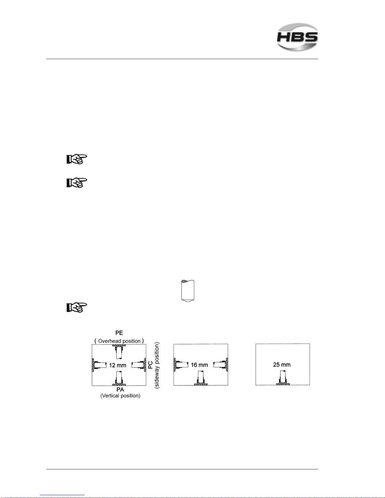
With shielding gas, you should only weld in position PA (vertical) because due to gravity, the shielding gas cannot prevent
flow of the molten metal.
5 Stud Welding Procedure
5.2 Functional Principle of Stud Welding
Page 31

IT 1002 Order No BA 93-66-1206 Issue 03.11.08 31
5.2.3 Short-Cycle Drawn-Arc Stud Welding with Shielding Gas
Short-cycle drawn-arc welding with shielding gas is used for welding elements within a
diameter range of 3 to 12 mm (nominal diameter without flange) and welding times
between 5 and 100 ms.
Due to the short welding times, the energy input and the weld pool are so small that also
welding elements up to 12 mm diameter can be welded on thin workpieces.
Normally, welding elements with flange (according to current standards, see appendix)
are used, which forms a larger welding area compared with the shaft diameter. In this
way, higher tensional forces than in the stud shaft can be transmitted in spite of some
pores in the weld zone. To minimize pore formation, the use of shielding gas for stud
diameters upwards of 8 mm is recommended.
5.2.4 Drawn-Arc Capacitor-Discharge Stud Welding
With drawn-arc capacitor-discharge stud welding, the welding energy is taken from a
capacitor. As a result, welding currents are very high and welding times (< 10 ms) very
short. Normally, a weld pool protection is not required. The process is mainly used for
welding elements in a diameter range of up to 8 mm.
5 Stud Welding Procedure
5.2 Functional Principle of Stud Welding
Page 32

32 IT 1002 Order No BA 93-66-1206 Issue 03.11.08
5.3 Welding Preparation
Read the safety instructions in chapters 1, 3 and 5.
Observe the workplace requirements (chapter 3, ”Starting-up").
Check all cables and connections for proper condition.
Replace immediately defective cables and cable connections to avoid electrical
shocks.
Check the chuck for proper seat (see operating manual of according welding
gun).
Before welding, make sure that the bellows are checked for damage and proper
seat.
5.4 High-strength Welds
The following must be removed both from the weld zone and the ground clamp
connection areas:
– paint, oil and any other impurities,
– rust,
– non-conductive coatings from surface treated workpieces.
Weld to smooth and flat surfaces only.
For welding to pipes or punched plates consult our responsible
application manager (address of customer service see page ii).
5.5 Determination of Welding Parameters
The adjustment of welding parameters on the power unit (e.g. welding time) or on the
welding gun (e.g. lift) depends amongst others on
– material of the welding element
– diameter of the welding element
– material of the workpiece
The guidelines should be verified by test welding on the actual material and be changed
if necessary. For an assessment of welding results, see sections 5.8 and 5.9.
Determination of welding time
Data given in the following table are only guidelines. They must
be verified by trial welds on the actual material according to
actual standards and DVS guidelines (see appendix). Before
you use another lot of welding elements, carry out some trial
welds to verify the parameter setting.
5 Stud Welding Procedure
5.3 Welding Preparation
Page 33
IT 1002 Order No BA 93-66-1206 Issue 03.11.08 33
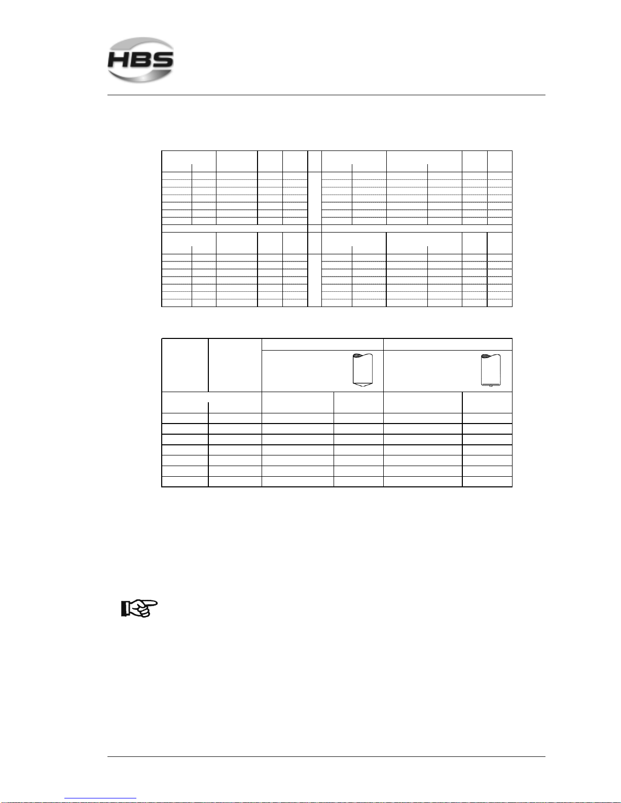
Setting of power unit *)
eff. Diam eter
(mm/inches)
Welding
current A
Welding
time (ms)
Welding
current A
Welding
time (m s)
(metric) (imperial) (metric) (imperial) (metric/mm) (imperial)
M3 1/8" not standar dized - - 3 #4 or 12 gage 3 #4 or 12 gage 240 60
M4 5/32" not standar dized - - 4 #8 4 #8 320 80
M5 3/16" not standar dized - - 5 #10 or 3/16" 5 #10 or 3/16" 400 100
M6 1/4" 4,7/0.19 380 100 6 1/4" 6 1/4" 480 120
M8 5/16" 6,2/0.24 500 130 8 5/16" 8 5/16" 640 160
M10 3/8" 7,9/0.31 640 160 10 7/16" 10 7/16" 800 200
M12 1/2" 9,5/0.37 760 190 12 1/2" 12 1/2" 960 240
eff. Diam eter
(mm/inches)
Welding
current A
Welding
time (ms)
Welding
current A
Welding
time (m s)
(metric) (imperial) (metric) (imperial) (metric/mm) (imperial)
M3 1/8" not standar dized - - M3 1/8" 4 #8 400 60
M4 5/32" not standar dized - - M4 5/32" 5 #10 or 3/16" 500 80
M5 3/16" not standar dized - - M5 3/16" 6 1/4" 600 100
M6 1/4" 5,4/0.21 432 108 M6 1/4" 7 0.28" 700 110
M8 5/16" 7,2/0.28 576 144 M8 5 /16" 9 0.35" 900 140
M10 3/8" 9/0.35 720 180 M10 3/8" 11 0.43" 1000 190
M12 1/2" 10,9/0.43 872 218 M12 1/2" not s tandardized - - -
Designati on
RD
(MR)
Designation
UD / Pins
eff. Diam eter
Designati on
DD
(MD)
Designation
FD
eff. Diam eter
Setting of welding gun
Plunging depth Lift Plunging dept h Lift
(metric/mm) (imperial)
3 #4 or 12 gage 1,0 1,0 2,5 1,5
4#81,01,02,51,5
5 #10 or 3/16" 1,0 1,0 2,5 1,5
6 1/4" 1,0 1,0 2,5 1,5
8 5/16" 1,0 1,0 2,5 2,0
10 7/16" 1,5 1,5 3,0 2,0
12 1/2" 2,0 2,0 3,0 2,5
Eff. diameter
Preferably under shielding gas Preferably with ceramic ferrule
Welding element with
conical face
Welding element with
conic al or
plane face
*)
When welding with shielding gas, a 10% longer time is normally selected.
When welding alloyed steel, a 10% lower current is normally selected.
The given values apply to weldings in the welding position PA. The welding time shall be
reduced for welding in the welding position PC.
In the case of short cycle stud welding, the welding time is less than 100 ms. It depends not
only on the stud diameter, but also on the available current intensity (I[A] = min. 100 x Ø (mm)).
The welding time should be as short as possible in the case of welding without weld pool
protection.
Welding energy is only selected by welding time.
Further notes on
– welding elements
– prestress at installation (tie load) and torque
– material combinations
see appendix and operating manual of the according welding
gun.
5 Stud Welding Procedure
5.5 Determination of Welding Parameters
Page 34
34 IT 1002 Order No BA 93-66-1206 Issue 03.11.08
5.6 Switching on the Power Unit
Improper operation of the stud welding unit is
LIFE-THREATENING!
First read the safety instructions in chapters 1, 3 and 5.
Insert the primary plug of the power unit into an appropriate socket.
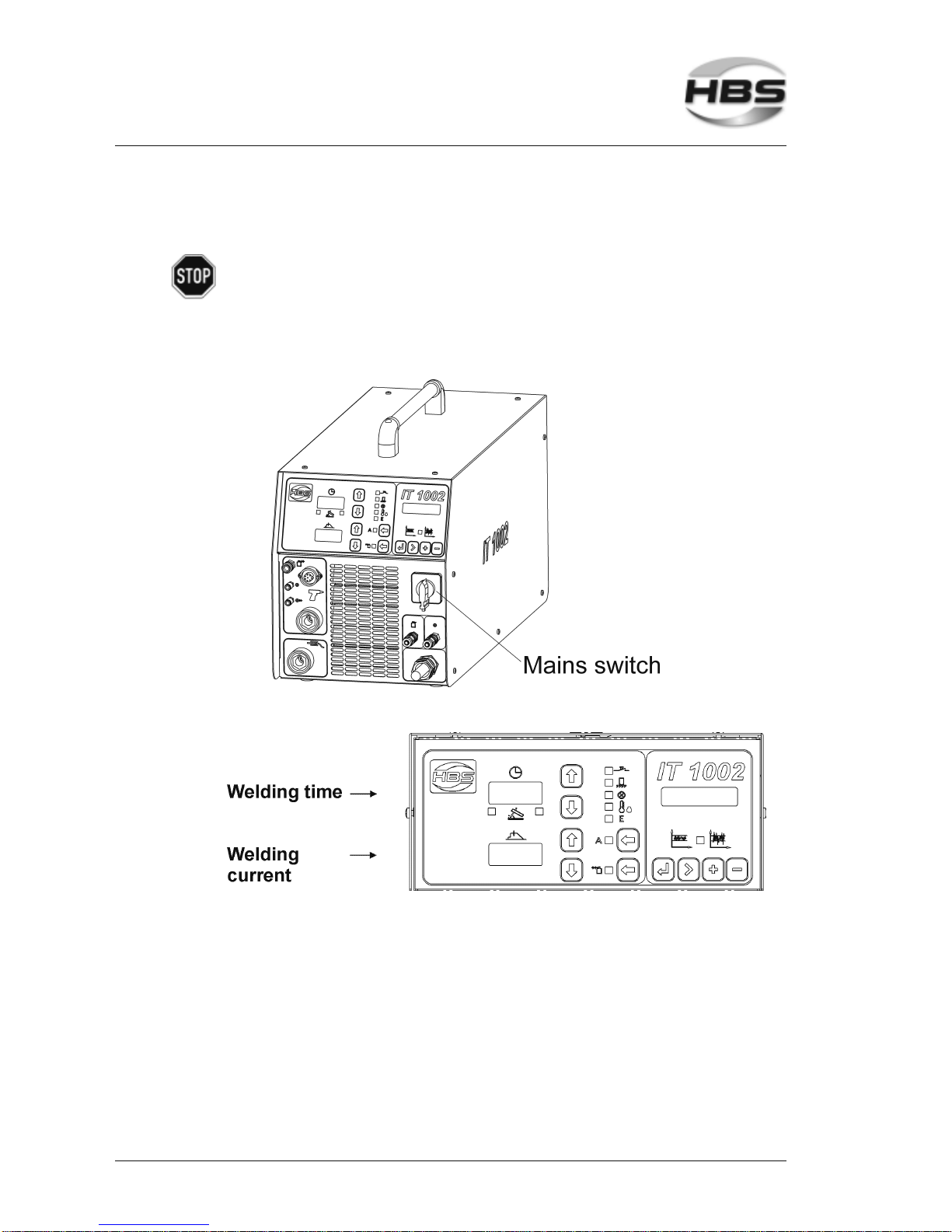
Switch on the power unit with the mains switch.
The digital display shows the adjusted welding time and welding current.
5 Stud Welding Procedure
5.6 Switching on the Power Unit
Page 35
IT 1002 Order No BA 93-66-1206 Issue 03.11.08 35
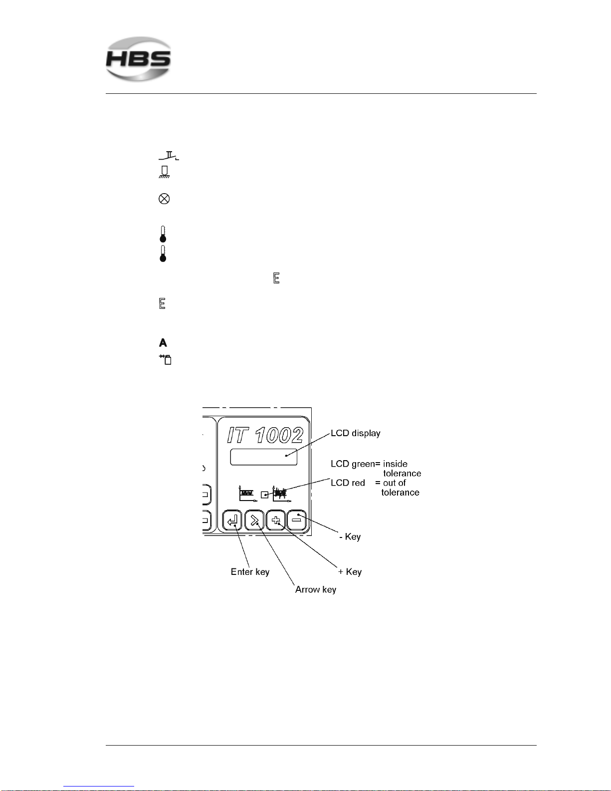
There is a luminous indication (LED) to the right of the display:
Yellow – lights if the welding gun button is triggered
Yellow – lights if there is electrical contact between welding element
and workpiece
Red – on, power unit is locked
• after welding, until there is electrical contact with the
workpiece
Green – on, power unit is ready for welding
Red – on, power unit is locked
• if the power unit is overheated (displays show 8888 and
LED lights).
After a short cooling period, the work can continue.
Red – on, power unit is locked
• if the power unit is overheated
• if there is a malfunction of the power unit
Green – lights, automatic mode is switched on
Green – lights, shielding gas is switched on
The LCD display shows the last set values.
5 Stud Welding Procedure
5.6 Switching on the Power Unit
Page 36

36 IT 1002 Order No BA 93-66-1206 Issue 03.11.08
Display
2 x 16 digits 5 mm height, with back-lighting
Keys
ENTER, Confirmation of selected function
ARROW, Marks the selected program item
PLUS, Increases the selected value
MINUS, Decreases the selected value
LED’s
They are linked to the process control (see section 5.6.7). The LED’s inform whether
the starting voltage value is in the tolerance range of the reference or not.
Green - value is inside the set tolerance range
Red - value is out of set tolerance range
Basic settings
Using the key Plus , you can enable the process sequence control. You can set the
machine according to your requirements. Call up the main menu with the enter key .
Then the following menu items are available:
- REFERENCE MODE Activate process sequence control
- SET DATE
- SET TIME
- SELECT LANGUAGE
Normally, you select the menu item with the arrow key and open it with the enter
key . To confirm settings and to quit a menu item is also carried out via the enter
key .
5.6.1 Adjusting the Welding Time
Set the welding time (digital display ) with the arrow keys
(⇑ longer – ⇓ shorter) on the display.
5 Stud Welding Procedure
5.6 Switching on the Power Unit
Page 37

IT 1002 Order No BA 93-66-1206 Issue 03.11.08 37
5.6.2 Adjusting the Welding Current
Set the welding current (digital display ) with the two arrow keys
(⇑ higher – ⇓ lower) on the display.
5.6.3 Adjusting the Gas Pre-Flow Time
If working with shielding gas, you have to set the gas pre-flow time. Adjust at the display,
how long the shielding gas should flow before the welding process starts. The gas flows
automatically until the welding gun is removed from the joined welding element.
Adjust the flow meter at the gas bottle to 8 to 16 liters/min (minimum 8 l/min.)
Press the shielding gas key, LED shielding gas on
The display welding time ( ) shows the gas pre-flow time
Set the gas pre-flow time with the two arrow keys (⇑ longer – ⇓ shorter).
After approx. 2 seconds, the display welding time ( ) automatically switches
back to the previously set welding time.
If you are working with ceramic ferrules, then trigger the
shielding gas key, the shielding gas LED is off. In this way, the
gas valve remains closed during the welding procedure.
5.6.4 Library Mode
In the library mode, you can call up and modify charging voltages, depending on stud
diameter (UD/pins).
Simultaneously press both arrow keys of welding time (⇓ shorter ⇑ longer) for
about one second. The display welding time shows 0-06 (06 means the set
welding current and welding time for stud diameter of 6 mm).
You can pre-select the stud diameter (6 mm to 12 mm) with both arrow keys
(⇓ shorter ⇑ longer). After about 3 seconds the display ( ) jumps onto the preselected welding time and the display ( ) onto the pre-selected welding
current.
In addition, you can modify the welding time and welding current individually by
pressing the arrow keys (as described above).
If you are working with shielding gas, different welding parameters for stud
diameters (from 6 mm to 12 mm) are available in library mode.
5 Stud Welding Procedure
5.6 Switching on the Power Unit
Page 38

38 IT 1002 Order No BA 93-66-1206 Issue 03.11.08
5.6.5 Electrode Mode
You can switch the power unit to electrode mode.
Simultaneously press both arrow keys (welding current ⇓ lower ⇑ higher) for
about one second. The display welding time shows EL.
You can pre-select the welding current (from 50 to 400 A) with both arrow keys
(⇓ lower ⇑ higher).
If you touch the work piece with the electrode, the power unit is switched on.
If you switch the power unit off and on, the power unit is
automatically reset to stud welding.
5.6.6 Adjusting the Stud Feeding Time (Blow Time)
If you are working in automatic mode, you must adjust the blow time. Use the
display to set the feeding time (blow time).
Adjust the selected compressed air supply to 6 bars
Press the key Automation, LED Automation lights
The display welding time shows the blow time ( )
Set the blow time with the two arrow keys (⇑ longer – ⇓ shorter)
The display welding time ( ) automatically switches back to the last set blow
time after approx. 2 s
If you do not work in automatic mode, press the key Automation,
LED
extinguishes. The gas valve remains closed.
5.6.7 Adjusting the Controls
To be able to assess the process sequence during welding, an average value is
calculated from the existing output voltage values.
You don’t need any special welding guns and/or additional welding cables for this
system of function monitoring.
During welding the reference, the micro controller determines a reference output voltage
value. This is the average value of eight consecutive weldings.
5 Stud Welding Procedure
5.6 Switching on the Power Unit
Page 39
IT 1002 Order No BA 93-66-1206 Issue 03.11.08 39
During standard working process, the current output voltage value is compared with the
reference output voltage value. If this value is out of the set tolerance range, the system
indicates a deviation which is displayed via LED’s. If desired, the unit can be locked after
a deviation was indicated.
As an option, you can manually enter an output voltage value. This value must be
determined by 8 reference wedings in advance. In this way, the output voltage value can
be stored for different program sequences. So you can store a special output voltage
value for each stud/lot dimension and carry out a process monitoring.
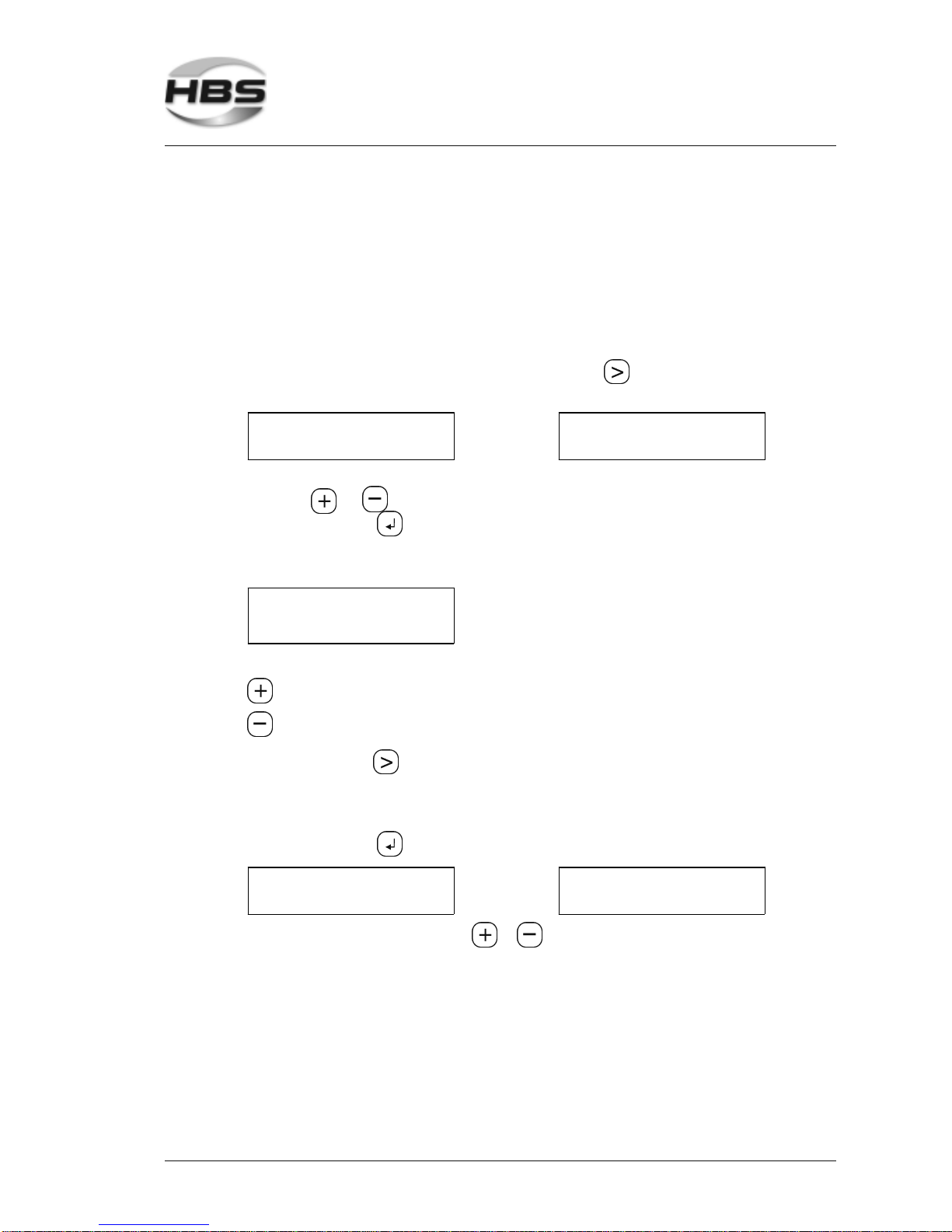
Change to the box Weld or Enter with the arrow key , the following menu is
displayed:
REFERENCE MODE
WELDING
REFERENCE MODE
ENTER
With sequence 1, you determine the reference value, sequence 2 is manual entry. Use
the keys or to select the menu items.
Press the enter key , the following menu is displayed:
Reference Mode Welding
REFERENCE MODE
TOLERANCE: 10%
Here you define the tolerance range
Increase tolerance range
Decrease tolerance range
With the arrow key you change the settings
1% - small tolerance range = high sensitivity
20% - large tolerance range = low sensitivity
Press the enter key , the following menu is displayed:
REFERENCE MODE
STOP: OFF
or
REFERENCE MODE
STOP: ON
You change the menu boxes with or .
5 Stud Welding Procedure
5.6 Switching on the Power Unit
Page 40
40 IT 1002 Order No BA 93-66-1206 Issue 03.11.08
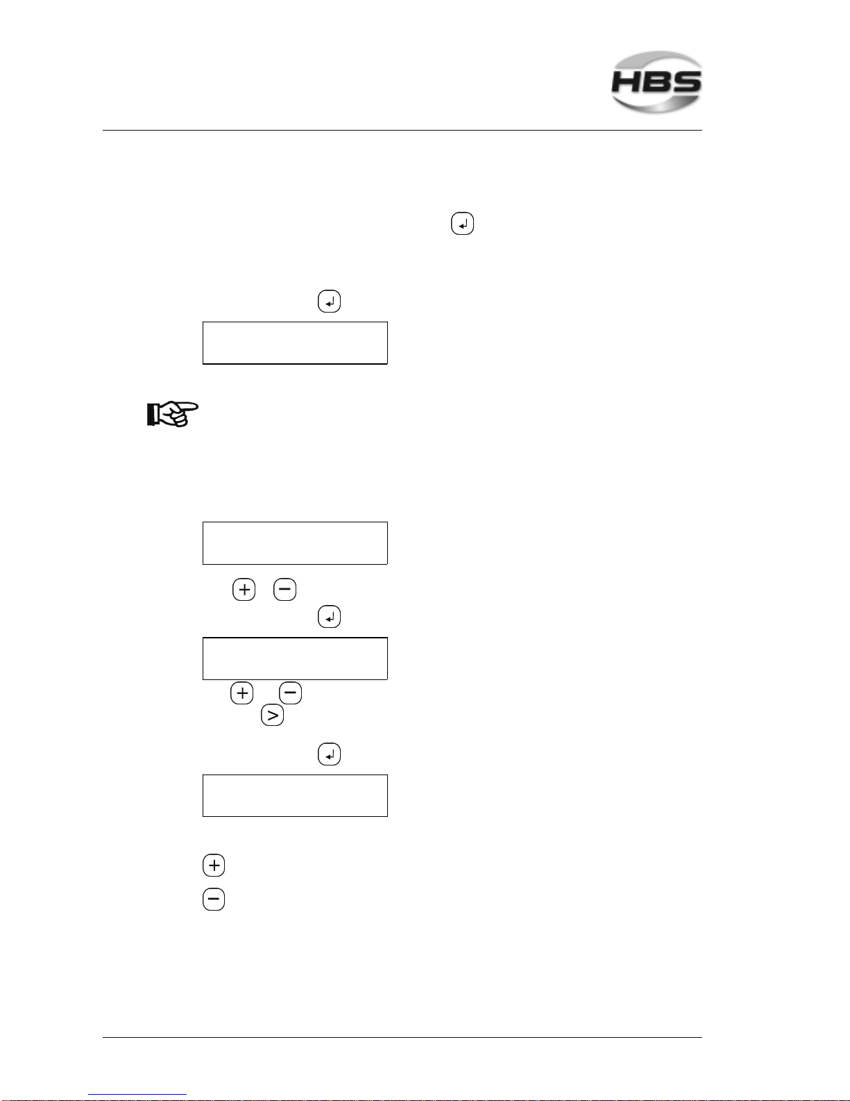
Stop with red >ON< - Your unit stops automatically if
output voltage value out of tolerance range. With a click
on the enter key , the unit is ready for welding
again.
Stop with red >OFF< - The unit continues to weld, LED’s show whether welds
are in or out of tolerance range.
Press the enter key , the following menu is displayed:
REF-U: 00.00V
REFERENCE: 8
Now carry out the 8 reference welds.
The welded reference value is deleted if a setting at the power
unit is changed during sequence 1 or if the power unit is
switched off.
New reference welding is required.
Reference Mode Enter
SELECTION PROGRAM
PRG 1: 25.00V
With or , you can select the programs 1 to 8.
Press the enter key , the following menu is displayed:
PROGRAM 1
U-REF: 25.00V
With and , you can enter the individual digits. You change the position with the
arrow key . U-REF 25.00V means that you define the set reference value 25V for
program place 1.
Press the enter key , the following menu is displayed:
PROGRAM 1
TOLERANCE: 10%
Here you define the tolerance range.
Increase tolerance range
Decrease tolerance range
5 Stud Welding Procedure
5.6 Switching on the Power Unit
Page 41
IT 1002 Order No BA 93-66-1206 Issue 03.11.08 41
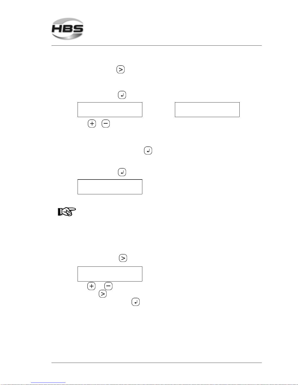
With the arrow key , you change the position
1% - small tolerance range = high sensitivity
20% - large tolerance range = low sensitivity
Press the enter key , the following menu is displayed:
PROGRAM 1
STOP: OFF
or
PROGRAM 1
STOP: ON
With or you change between the individual menu boxes
Stop with red >ON< - Your unit stops automatically if output voltage value is
out of tolerance range. With a click on the enter
key , the unit is ready for welding again.
Stop with red >OFF< - The unit continues to weld, LED’s show whether welds
are in or out of tolerance range.
Press the enter key , the following menu is displayed:
REF - U1: 25.00V
ACT - U: 00.00V
Now you can continue your welding.
The settings of the power unit must be checked after changes
of base material, lot of welding elements or settings of welding
gun.
With changed conditions, the reference value must be redetermined.
Adjusting the Date
Press the arrow key until the menu ‘Date’ is displayed.
ADJUSTING DATE
06.07.05
With and , you can enter the individual digits. You change the position with the
arrow key .
Confirm with the enter key .
5 Stud Welding Procedure
5.6 Switching on the Power Unit
Page 42
42 IT 1002 Order No BA 93-66-1206 Issue 03.11.08
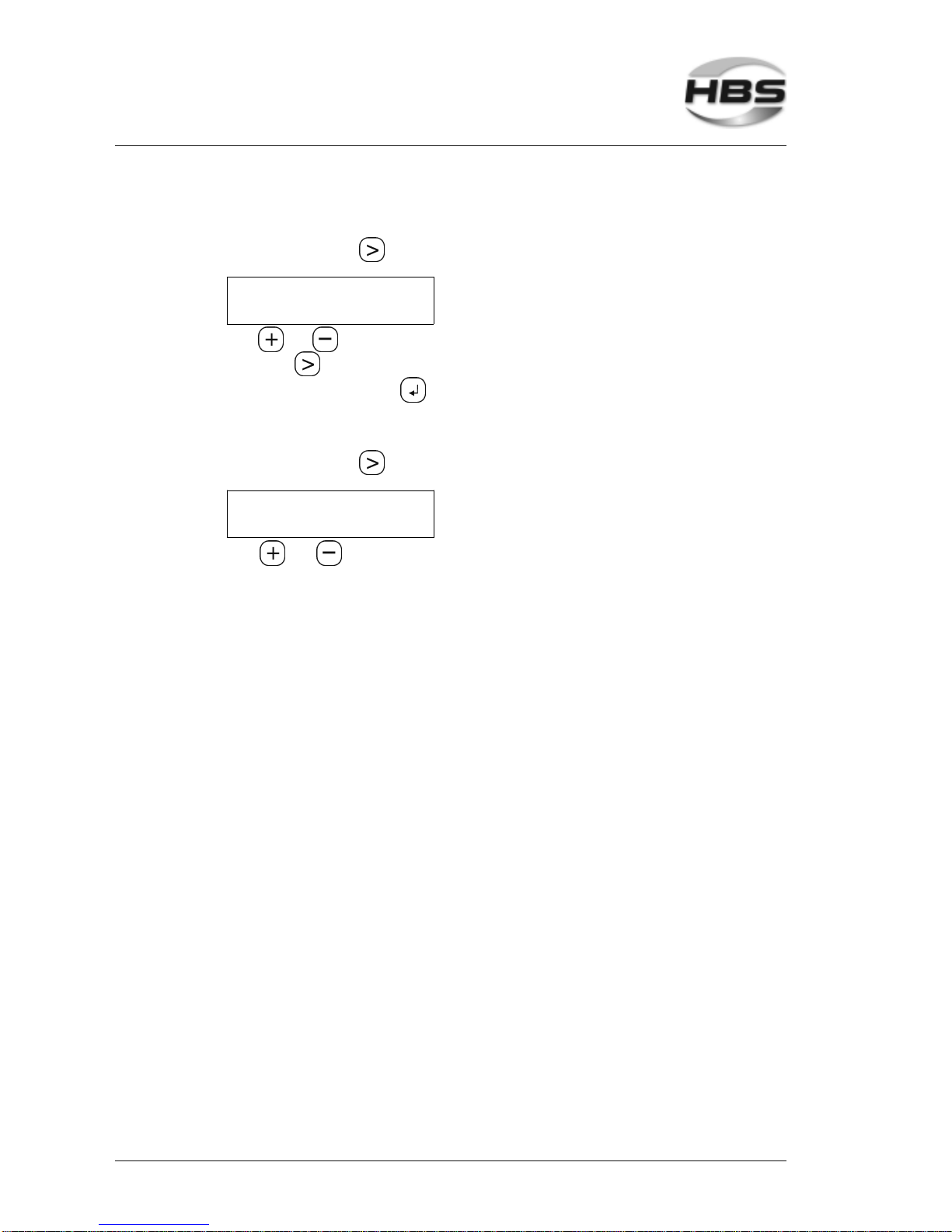
Adjusting the Time
Press the arrow key until the menu ‘Time’ is displayed.
ADJUSTING TIME
15:07:30
With and , you can enter the individual digits. You change the position with the
arrow key .
Confirm with the enter key .
Adjusting the Language
Press the arrow key until the menu ‘Language’ is displayed.
SELECTION LANGUAGE
ENGLISH
With and , you can enter the individual language.
5 Stud Welding Procedure
5.6 Switching on the Power Unit
Page 43

IT 1002 Order No BA 93-66-1206 Issue 03.11.08 43
5.7 Welding Procedure
Improper operation of the stud welding unit is
LIFE-THREATENING! The stud welding unit must only be
operated by qualified personnel (see chapter 1).
Observe the safety instructions in chapters 1, 3 and 5.
Prepare the stud welding unit, the ground connection, and the workpiece
according to the instructions given in the operating manual.
Chapter 5 contains guideline for welding parameters. The data
given are only guidelines. They must be verified by trial welds
on the actual workpiece according to actual standards and DVS
regulations (see appendix).
During the actual welding process, you must expect red-hot welding
spatters, possibly liquid spatters, a flash, and a loud bang may occur
> 90dB (A). Inform any collegues who are occupied in the vicinity of
the welder about the bang.
Wear always your personal protective equipment according to actual
standards (see appendix).
Insert the welding element into the chuck.
As soon as the power unit is ready for the welding process,
place the welding gun vertically against the workpiece,
push the welding gun firmly with both hands onto the workpiece until the welding
gun support (distance device) is evenly seated on the workpiece,
hold the welding gun firmly, still, and straight,
take care that you do not touch any metallic part of the welding gun,
press the trigger button of the welding gun.
This initiates the welding process.
The welding process can only be initiated, if the current circuit
is closed, i.e. the welding element is in electrical contact with
the base material.
After the welding process has been completed, withdraw the
welding gun straight back from the welding element. If you
remove the welding gun at an angle, the chuck will be stretched, this reduces its life expectancy.
You can now insert a new welding element in the chuck and repeat the welding process
as described above.
5 Stud Welding Procedure
5.7 Welding Procedure
Page 44
44 IT 1002 Order No BA 93-66-1206 Issue 03.11.08
5.7.1 Automatic Welding Mode
In automatic mode, you can use the welding gun PAH-1 or the welding head KAH 412
for welding elements from 3 to 8 mm Ø.
You can manually insert the welding elements into the welding gun (semi-automatic
mode) or you can use a fully-automatic stud feeding system.
You can order the fully-automatic stud feeder under the following order number:
Stud diameter Order No.
VBZ-3 Ø 3 94-66-103 B
Ø 4 94-66-104 B
Ø 5 94-66-105 B
Ø 5 x-mas tree studs 94-66-153 B
Ø 6 94-66-106 B
Ø 6 x-mas tree studs 94-66-163 B
Ø 7,1 94-66-171 B
Ø 8 94-66-108 B
other Ø on request
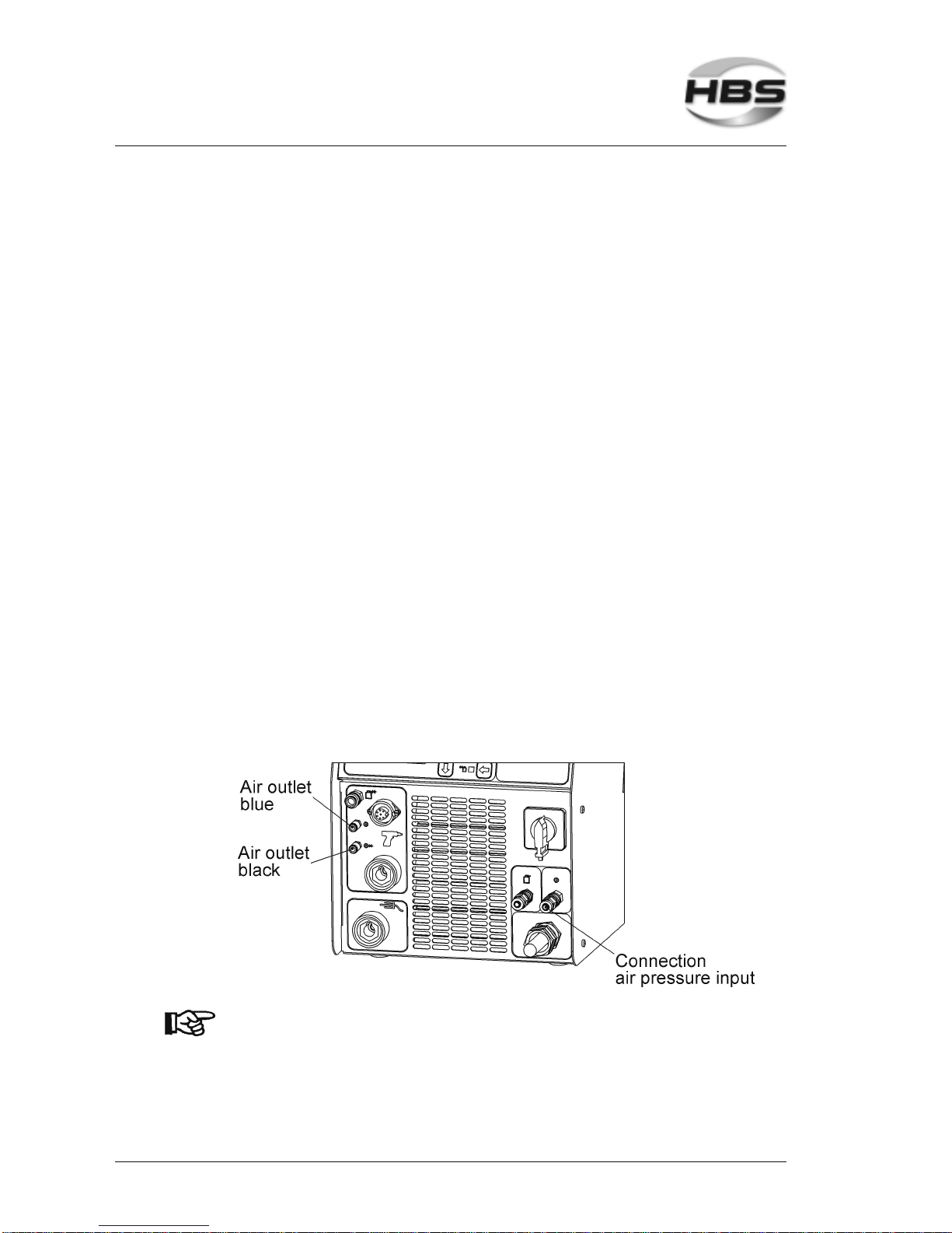
Plug the air connectors of the welding gun into the air outlet bushes at the front
of the power unit. Observe the color markings:
black = switched air (during stud feeding time)
blue = continuous air, for pressing the stud into the
chuck and as a stop
The power unit controls the air between these two bushes.
If the conduits are wrongly connected, feeding and welding
malfunctions will occur.
5 Stud Welding Procedure
5.7 Welding Procedure
Page 45
IT 1002 Order No BA 93-66-1206 Issue 03.11.08 45
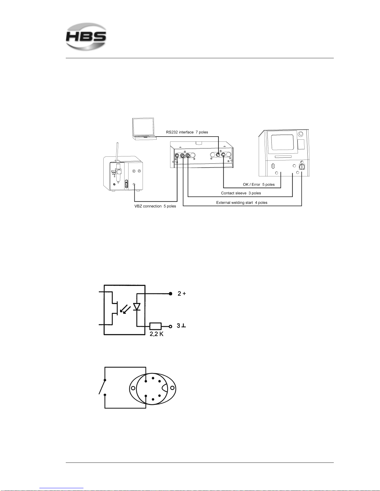
Connect the compressed air supply to the compressed air inlet of the power unit
(6 bar/800 l/min).
Connect the control socket of the feeding unit (front side) to the control socket of
the power unit (rear side).
Feeding unit External control
5.7.2 External Welding Start
To integrate the power unit in CNC stud welding systems, an additional external welding
start is provided at the rear side of the power unit (control socket 4, pin 2; 3). The inlet
is designed for 24 V DC control units (signal time min. 200 ms).
External welding start:
Min. switch current
I
min
= 10 mA ( min. 22 V)
I
max
= 20 mA
A welding start can also be provided with the welding gun control plug at the front side
of the power unit (pin 3; 4).
To start welding, you must shortcircuiting pin 3 and 4 for at least
100 ms.
Power unit
5 Stud Welding Procedure
5.7 Welding Procedure
Page 46
46 IT 1002 Order No BA 93-66-1206 Issue 03.11.08
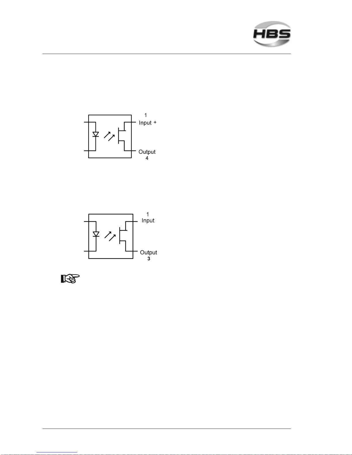
5.7.3 Charging Supervision (ready)
For best control of time sequence of CNC machines, a charging supervision is provided.
As soon as the power unit is ready for welding, the transistor is switched on (control
socket 4poles, pin 1; 4).
Operating voltage 24 V DC
Current capacity max. 50 mA
5.7.4 Contact
For best control of time sequence of CNC machines, an external contact inquiry
between work piece and welding head is provided. As soon as a contact is recognized,
the transistor is swiched on (control socket 3 poles, pin 1; 3).
Operating voltage 24 V DC
Current capacity max. 50 mA
Operating the automatic welding head KAH 412 (see operating
manual).
5 Stud Welding Procedure
5.7 Welding Procedure
Page 47
IT 1002 Order No BA 93-66-1206 Issue 03.11.08 47
5.7.5 RS-232 Interface
Via the serial interface of the power unit, current monitoring data can be output in ASCII
format for a possible record.
A data cable is required which you can order at HBS as an accessory (order
no. 80-70-308).
Example for data output at the serial output (e.g. Microsoft® Hyper Terminal)
Counter Date Time Mode Nom. Curr. Nom. Time Gas Time R/M Nom. Volt. Stop Tolera nce Act. Curr. Act. Volt. Act. Time Energy OK/ERR
14776 13.09.2004 10:00:25 REF8 950A 15ms 900ms R 32.82V OFF 15% 943A 32.82V 15ms 464W s
14777 13.09.2004 10:00:39 REF7 950A 15ms 900ms R 31.69V OFF 15% 942A 31.69V 15ms 447W s
14778 13.09.2004 10:00:50 REF6 950A 15ms 900ms R 33.34V OFF 15% 942A 33.34V 15ms 470W s
14779 13.09.2004 10:01:01 REF5 950A 15ms 900ms R 32.20V OFF 15% 940A 32.20V 15ms 454W s
14780 13.09.2004 10:01:19 REF4 950A 15ms 900ms R 32.82V OFF 15% 943A 32.82V 15ms 464W s
14781 13.09.2004 10:01:31 REF3 950A 15ms 900ms R 33.22V OFF 15% 943A 33.22V 15ms 469W s
14782 13.09.2004 10:02:03 REF2 950A 15ms 900ms R 31.75V OFF 15% 940A 31.75V 15ms 447W s
14783 13.09.2004 10:02:50 REF1 950A 15ms 900ms R 32.39V OFF 15% 942A 32.39V 15ms 457W s
14784 13.09.2004 10:03:00 950A 15ms 900ms R 32.53V OFF 15% 940A 31.36V 14ms 412Ws OK
14785 13.09.2004 10:03:18 950A 15ms 900ms R 32.53V OFF 15% 943A 32.54V 14ms 429Ws OK
14786 13.09.2004 10:03:28 950A 15ms 900ms R 32.53V OFF 15% 944A 33.08V 14ms 437Ws OK
14787 13.09.2004 10:03:38 950A 15ms 900ms R 32.53V OFF 15% 945A 32.44V 14ms 429Ws OK
Output serial inte rface IT units
Such data can be evaluated with a terminal program (e.g. Hyper Terminal) (see
appendix: Hyper Terminal).
Connection settings of the serial interface at a PC or laptop:
Bits per second 115.200
Data bits: 8
Parity: None
Stopbits: 1
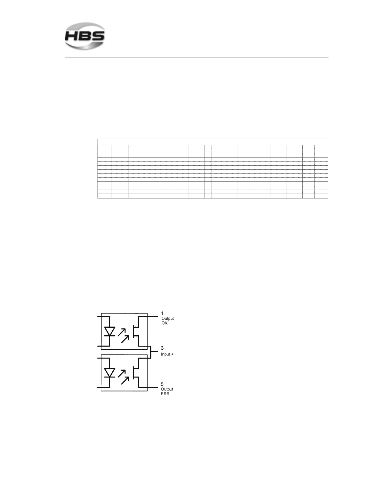
5.7.6 OK/ERR
This interface informs your control whether the welded value is inside or outside the
tolerance range.
Operating voltage 24 V DC
Current capacity max. 50 mA
5 Stud Welding Procedure
5.7 Welding Procedure
Page 48
48 IT 1002 Order No BA 93-66-1206 Issue 03.11.08
5.8 Checking the Quality of the Weld
You can check the quality of the weld by means of a visual inspection and a bending
test.
See also actual standards in the appendix “Arc stud welding of
metallic materials“, in section irregularities and corrective
actions.
5.8.1 Visual Inspection
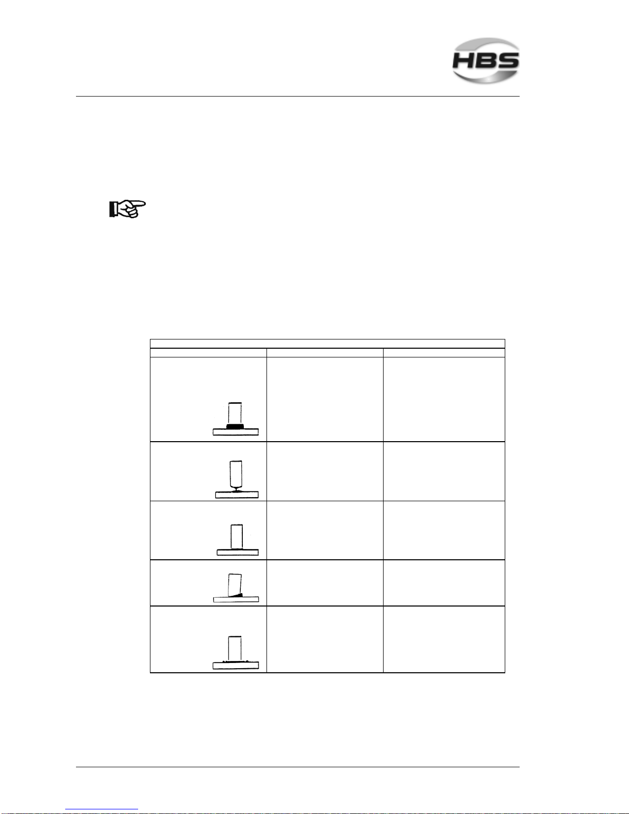
A visual inspection must be carried out with each welding element.
Shape, size, evenness, and color of the weld collar are assessed during a visual
inspection. The length of a welded element should be 2 to 3 mm shorter than before
welding.
Condition Possible cause Correctiv e actions
Weld c ollar ev enly, s hiny, a nd complete
Length of w elding element w ithin tolerance
af ter w elding
- Correc t parameters - None
Contraction of w eld collar - Plunging depth or lift too low - Increas e plunging depth, c heck lif t and
center in g of the c eramic ring
w eldin g element too long - Welding energy too high
- Ceramic ring not centered correctly
- Decreas e current and/ or time
- Check center ing
Weakly developed, unev en we ld collar w ith
mat su rf a ce
- Welding energy too low - Inc rease curr ent and/or time
Welding element too long - Ceramic ring is humid - Rebake ceramic rings in a f urnace
Single-sided w eld collar - Ar c blow effec t - See arc blow ef fect
Undercut - Ceramic ring not centered correctly - Check centering
Weld c ollar low , s hiny s urf ace w ith many
spatter s
- Welding energy too high - Decrease cur rent and/or time
Welding element too s hort - Plunging speed too high - Adjust plunging depth and/or damping f actor
Visual Inspection
5 Stud Welding Procedure
5.8 Checking the Quality of the Weld
Page 49
IT 1002 Order No BA 93-66-1206 Issue 03.11.08 49
5.8.2 Bending Test
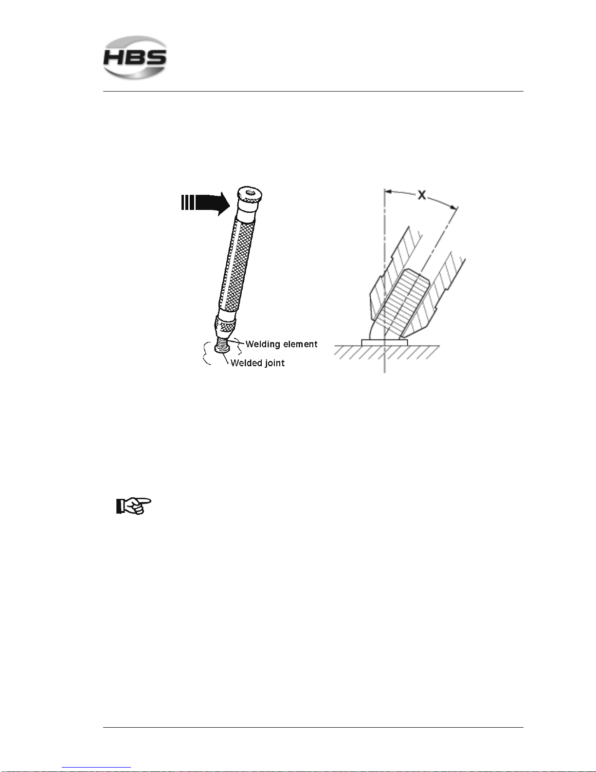
You can purchase from HBS a bending device with inserts for various diameters of the
welding elements.
The bending test serves as an easy work sample and as a check for the selected welding
parameters.
Bend the welding element with the bending device once by 60°.
Carry out the test in different directions.
The bending test is passed if a crack or a fracture of the welded zone does not occur.
Please note the instructions on fault recognition and corrective actions in
chapter 5.
You don’t need to test all studs. It is sufficient to carry out stud
tests at random.
If the strength of the joint is inadequate, then:
check the setting of the stud welding unit
check whether the surface of welding element and base material are clean and
electrically conductive (must be free from scale, oil, paint, oxide layers)
grind off hardened workpiece surfaces (e.g. roll hardening).
Check the piston of the welding gun for ease of movement.
5 Stud Welding Procedure
5.8 Checking the Quality of the Weld
Page 50
50 IT 1002 Order No BA 93-66-1206 Issue 03.11.08
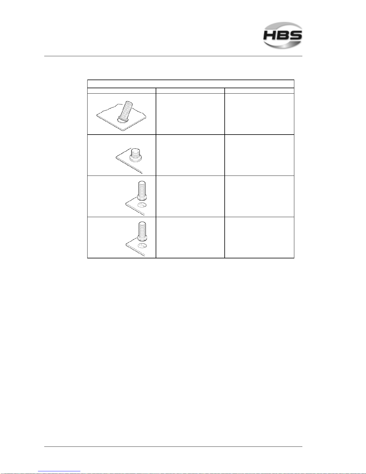
Type of fracture Possible cause Corrective acti ons
Base material buck ling - Correct paramet ers - none
Fracture in welding element
above weld collar
- Correct parameters - none
Fracture in the weld metal
Many pores
- Welding energy too low
- Plunging speed too low
- Unsuit able stud/base
material combi nation
- Increase welding energy
- Increase plunging speed
- Replace welding el ement or
workpiece
Fracture in the weld metal
Shiny fracture
surface
- Welding time too s hort - Increase welding time
Bending Test
5 Stud Welding Procedure
5.8 Checking the Quality of the Weld
Page 51
IT 1002 Order No BA 93-66-1206 Issue 03.11.08 51
5.8.3 Arc Blow Effect
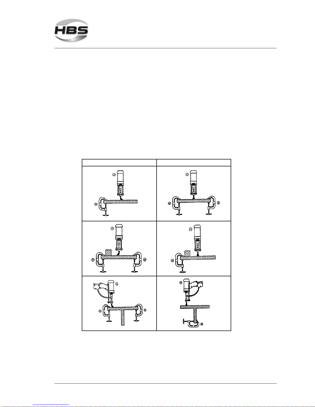
A so called arc blow effect can occur with unproportionally distributed ground connections in relation to the base material mass, varying material distribution, or welding at
the edge of a workpiece. This is an undesired deflection of the arc. It causes a singlesided melting of the stud material, increased pore formation, and undercuts in the
welding area.
The arc blow effect is proportional to the current and can be influenced by symmetric
installation of the ground clamps, by fitting of compensation masses, or by rotating the
welding gun around its vertical axis (applies for welding guns with external welding
cable).
Arc blow effects and some corrective actions
(according to standards, see appendix)
Cause Corrective action
5 Stud Welding Procedure
5.8 Checking the Quality of the Weld
Page 52
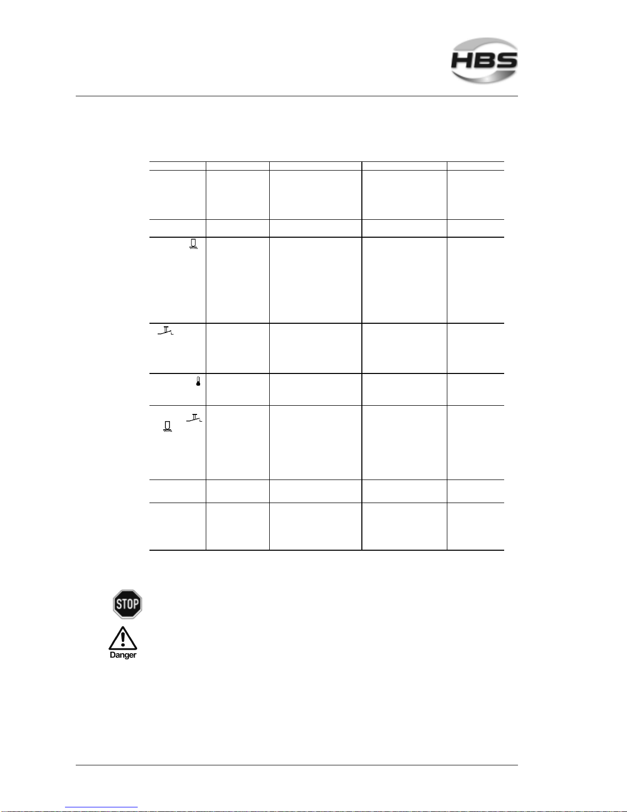
52 IT 1002 Order No BA 93-66-1206 Issue 03.11.08
5.9 Malfunctions and Corrective Actions
Malfunction Possible cause Fault finding Corrective action Carried out by
Primary s witch does
not re st in position 1
Primary sw itch
def ective
Check primary s witch *) Replace primar y sw itch *) Qualif ied per sonnel
Fuse F4 1 AF for
primary sw itch
def ective
Check voltage supply of primary
sw itch *)
Replac e fuse F4 1 AF *) Qualified personnel
Pr imary cable def ective Check primary c able f or breaks *) Replace primary cable *) Qualif ied pers onnel
No LED display at the
front
Fuse F5 1 AF defective Check fuse F5 1 AF *) Replace fus e F5 1 A F *) Qualif ied per sonnel
No C-display No ground connection Check ground connection on
workpiece
Tight en ground connection
properly
Qualif ied per sonnel
Welding gun not
connected
Check welding gun connection Connect w elding gun properly Instruc ted personnel
Transition resistance
(betw een stud and
w orkpiec e) too high
Check material surf ace Clean or grind material surf ace Instructed personnel
Ground cable broken Check ground cable *) Replace ground cable *) Qualified personnel
Welding gun c able
broken
Check welding gun cable *) Replace w elding gun cable *) Qualified personnel
No display Defec tiv e connecting
line of w elding gun
Check function of connec ting line *) Replac e connecting line *) Qualif ied per sonnel
Welding gun tr igger
button defective
Check control cable for electrical
flow w ith tr igger ed s tart button *)
Replac e w elding gun trigger
button *)
Qualif ied per sonnel
Control cable broken Check control cable for electrical
flow *)
Replac e control cable *) Qualified personnel
Continuous ly red
display:
Display 8888
Welding seque nce too
fast
Pow er unit resets automatically Let sw itched on pow er unit cool
dow n, power unit resets
automatically
Instructed personnel
Welding gun does not
lift, in spite of
and
No lif t adjus ted Check settings of welding gun Modify s et parameters Instr ucted personnel
Short circuit of solenoid
circuit of the welding
gun
Check resistance value of control
cable (18 Ω to 22 Ω) betw een Pin 1
and Pin 2 *)
Replac e control cable plug,
control cable, solenoid *)
Qualif ied per sonnel
Solenoid defe ctiv e Check s olenoid (1 8 Ω to 22 Ω) *) Replace solenoid *) Qualified personnel
Fuse F3 4 AF defective Check fuse F3 4 AF *) Replace fus e F3 4 A F *) Qualif ied per sonnel
Lif ting imposs ible So lenoid cir cuit
interrupted
Check resistance value at control
cable plug (18 Ω to 22 Ω) betw een
Pin 1 and Pin 2 *)
Replace soleno id or contro l lin e *) Qualif ied personnel
No shielding gas Shielding gas not
connected
Check shielding gas c onnec tion Connec t s hielding gas Instructed personnel
Shielding g as co ntrol no t
enabled
Check shielding gas c ontr ol for
activity
Sw itc h on shielding gas c ontrol Instructed personnel
Shielding g as va lve
defective Check shielding gas valve *) Replace shielding gas valve *) Qualified personnel
Actions marked with *) must only be carried out by qualified
electricians!
If none of the actions is successful, please contact our service
department.
5 Stud Welding Procedure
5.9 Malfunctions and Corrective Actions
Page 53
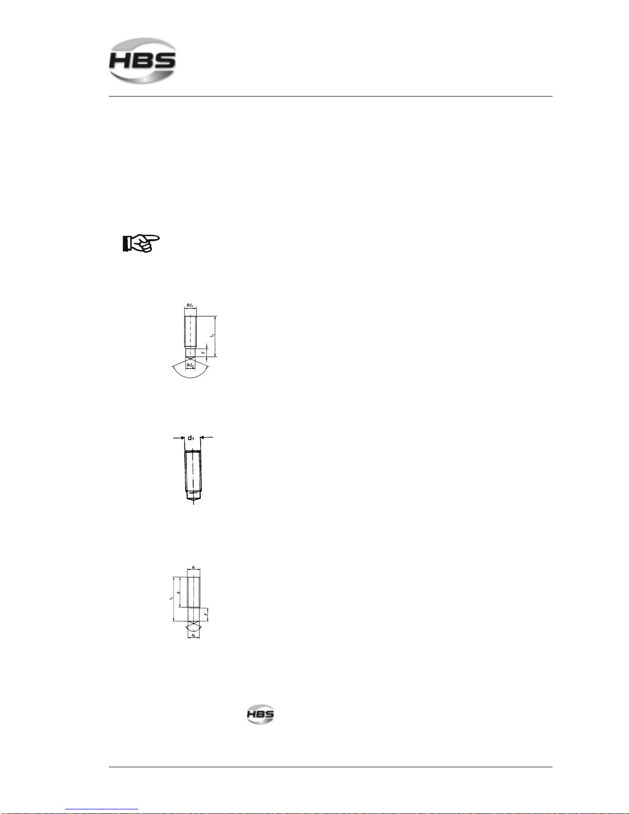
IT 1002 Order No BA 93-66-1206 Issue 03.11.08 53
5.10 Welding Elements
The stud welding unit must be suitable for welding the welding elements to be used.
Observe the instructions in the operating manuals.
Welding elements are mainly manufactured with the cold formed process.
We recommend the following standard welding elements (see appendix).
Use only welding elements of the same lot. Take particular care
not to mix-up different lots. Slightest variations in geometry of
the welding elements, especially of the ignition tip, require
modified settings of the welding process.
Threaded stud RD (MR) Diameter Length
Ceramic Shielding gas *)
M6 15-40 mm 83-50-006 83-51-006
M8 15-50 mm 83-50-008 83-51-008
M10 20-55 mm 83-50-010 83-51-010
M12 25-60 mm 83-50-012 83-51-012
M16 30-65 mm 83-50-016 83-51-016
Chuck
Materials: S235 / St37.3k (4.8) / 1.4301, 1.4303
Threaded s tud DD (MD) Diameter Length
Ceramic Shielding gas *)
M6 15-30 mm 83-50-006 83-51-006
M8 15-50 mm 83-50-008 83-51-008
M10 20-55 mm 83-50-010 83-51-010
M12 25-60 mm 83-50-012 83-51-012
M16 30-65 mm 83-50-016 ---
Chuck
Materials: S235 / St37.3k (4.8) / 1.4301, 1.4303
Threaded stud PD (MP) Diameter Length
Ceramic Shielding gas *)
M6 15-40 mm 83-50-006 83-51-006
M8 20-50 mm 83-50-008 83-51-008
M10 20-160 mm 83-50-010 83-51-010
M12 25-160 mm 83-50-012 83-51-012
M16 30-160 mm 83-50-016 ---
Chuck
Materials: S235 / St37.3k (4.8) / 1.4301, 1.4303
* Please use only welding elements without aluminum ball.
5 Stud Welding Procedure
5.10 Welding Elements
Page 54
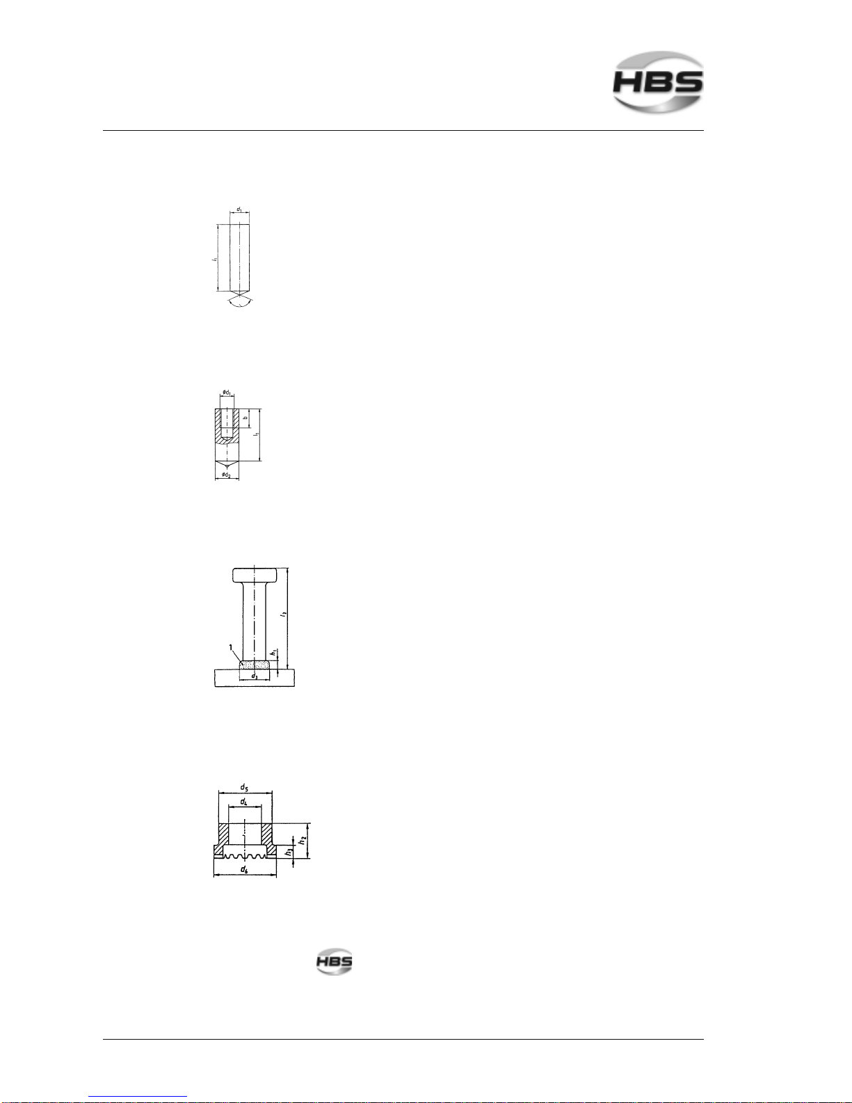
54 IT 1002 Order No BA 93-66-1206 Issue 03.11.08
Pin UD (S) Diameter Length
Ceramic Shielding gas *)
6 20-50 mm 83-50-006 83-51-006
8 20-50 mm 83-50-008 83-51-008
10 20-80 mm 83-50-010 83-51-010
12 20-80 mm 83-50-012 83-51-012
16 25-80 mm 83-50-016 ---
Chuck
Materials: S235 / St37.3k (4.8) / 1.4301, 1.4303
Pin with internal thread MI (ID) Diameter Length
Ceramic Shielding gas *)
M10 20-50 mm 83-50-010 83-51-010
M12 20-50 mm 83-50-012 83-51-012
M16 20-50 mm 83-50-016 ---
Chuck
Materials: S235 / St37.3k (4.8) / 1.4301, 1.4303
Head stud SD Diameter Length Chuck ceramic
1/4" (6) 50-100 mm 83-53-006
3/8" (10) 50-175 mm 83-53-010
1/2" (13) 50-175 mm 83-53-012
5/8" (16) 50-175 mm 83-53-019
3/4" (19) 50-175 mm 83-53-019
7/8" (22) 75-200 mm 83-53-022
Materials: S235 / St37.3k (4.8) / 1.4301, 1.4303
Ceramic ferrule RF
for threaded stud RD
Diameter Ceramic ferrule support
6 80-31-095
8 80-31-120
10 80-31-150
12 80-31-170
16 80-31-205
Materials: S235 / St37.3k (4.8) / 1.4301, 1.4303
* Please use only welding elements without aluminum ball.
5 Stud Welding Procedure
5.10 Welding Elements
Page 55
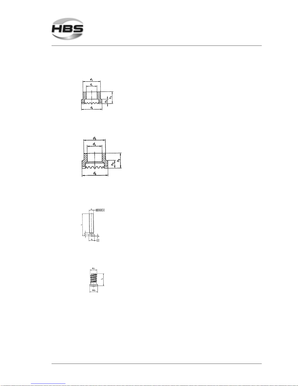
IT 1002 Order No BA 93-66-1206 Issue 03.11.08 55
- Ceramic ferrule P F for threaded stud PD
- Ceramic ferrrule UF for pins UD, MI
Diameter Ceramic ferrule support
6 80-31-095
8 80-31-120
10 80-31-150
12 80-31-205
16 80-30-116
Materials: S235 / St37.3k (4.8) / 1.4301, 1.4303
Ceramic ferrule UF for head stud SD Diameter Ceramic ferrule support
1/4" 80-30-206
3/8" 80-30-210
1/2" 80-30-213
5/8" 80-30-219
3/4" 80-30-219
7/8" 80-30-222
Materials: S235 / St37.3k (4.8) / 1.4301, 1.4303
Threaded stud FD
with flange
Diameter Length Chuck
M3 on request 82-50-003
M4 on request 82-50-004
M5 on request 82-50-005
M6 on request 82-50-006
M8 on request 82-50-008
Materials: S235 / St37.3k (4.8) / 1.4301
X-mas tree stud Diameter Length Chuck
5 on reques t 82-50-005
6 on reques t 82-50-006
Materials: S235 / St37.3k (4.8) / 1.4301, 1.4303
We look forward to consult you with view to special welding elements and other special
materials.
HBS Bolzenschweiss-Systeme GmbH & Co. KG
Felix-Wankel-Strasse 18
85221 Dachau / Germany
Phone +49 (0) 8131 511-0
Fax +49 (0) 8131 511-100
E-mail [email protected]
5 Stud Welding Procedure
5.10 Welding Elements
Page 56

56 IT 1002 Order No BA 93-66-1206 Issue 03.11.08
6 Switching off the Power Unit
This chapter describes what you should observe when you switch off the power unit
temporarily or completely.
6.1 Temporary Switching off
Switch off the power unit.
Unplug the control cable and the welding cable from the power unit.
Protect the power unit against ingress of fluids and foreign bodies.
6.2 Disposal
If you shut down the installation, you can return the complete power unit to HBS
(for address see page ii).
We will take care of environmentally correct material separation and disposal.
6 Switching off the Power Unit
6.1 Temporary Switching off
Page 57

IT 1002 Order No BA 93-66-1206 Issue 03.11.08 57
7 Care and Maintenance
7.1 Safety Instructions
Let maintenance and repair operations be carried out only by
qualified personnel or by your competent service technician.
Before starting any repair or maintenance operation, always switch
the power unit off and disconnect the primary plug.
Do not wear a wrist watch or any electrically conductive jewellery.
7.2 Regular Maintenance Operations
Clean the inner components of the power unit periodically of
dust. Use a dry washcloth or a brush. To open the power unit,
proceed as described in sections 7.1, 7.3 and 7.4.
Clean the surface of the power unit with a humid washcloth and a detergent.
Do not use any solvent containing cleaning agents. Solvent
containing cleaning agents may damage the surface of the
power unit.
7.3 Tools to be Used
– Cross-slotted screwdriver, size 2
7 Care and Maintenance
7.1 Safety Instructions
Page 58
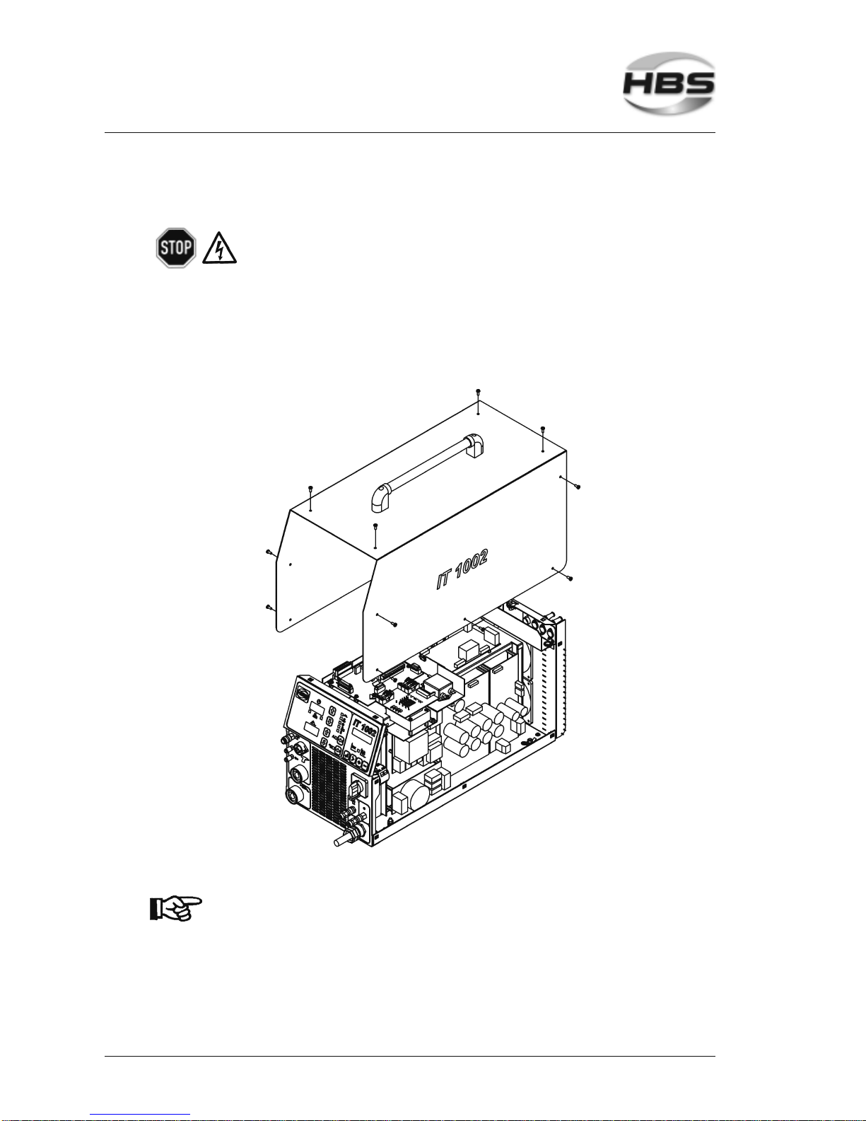
58 IT 1002 Order No BA 93-66-1206 Issue 03.11.08
7.4 Open the Power Unit
Open the power unit only if you are sufficiently qualified in
repairing electrical equipment.
Remove the 14 screws of the casing (5 at each side and 4 on top of casing
cover).
Carefully remove the cover and disconnect the ground cable on the inside of the
cover.
Now pull off the cover.
Re-assemble the power unit in reverse sequence.
Make sure that no cables are jammed or sheared during
assembly.
7 Care and Maintenance
7.4 Open the Power Unit
Page 59

IT 1002 Order No BA 93-66-1206 Issue 03.11.08 59
8 Appendix
In the appendix, there is information of interest regarding technical data, spare part lists,
accessories, standards, etc.
8.1 Technical Data
Power Unit IT 1002
for ARC stud welding according to current standards
Welding range #4 to 5/8", dia. 14 ga to 9/16"
(M3 to MR16, dia. 2 to 14 mm)
Welding material Mild steel, stainless steel, aluminum
Welding rate 1/2" (M12) = 25 studs/min
Welding current 1,000 A (max.)
Current adjustment range Stud welding 100 to 1,000 A,
electrode 50 to 400 A (stepless)
Welding time 5 to 1,000 msec (stepless)
Primary power 480/460 V, 3 phases, 50/60 Hz, 35 AT
(alternative input voltages available)
Primary plug 32 A (with 400 V mains)
Connected load 50 kVA (with 400 V mains)
Cooling type F (temperature controlled cooling fan)
Protection class IP 23 (also permits operation outdoors)
Operational and storage conditions According to current standards
Dimension L x W x H 25.98” x 11.02” x 13.39”
(660 x 280 x 340 mm) without handle
Weight 63.93 lbs (29 kg)
8 Appendix
8.1 Technical Data
Page 60

60 IT 1002 Order No BA 93-66-1206 Issue 03.11.08
8.2 Spare Parts
Spare part list power unit type IT 1002 (93-66-1206)
When ordering spare parts, please indicate order number and type of power unit.
Pos. Quantity Order No. Description
1 1 88-17-929 Power element complete
3 1 88-18-013 Terminal plate complete
4 5 m 80-50-404 Mains cable
5 1 88-17-997 Supply module complete
7 1 88-13-159 Front plate complete
8 1 80-10-1140 Label mat white
9 1 88-13-167 Shielding gas module
11 1 88-14-157 Adapter control
13 1 88-13-180 Cover
14 1 80-50-045 Control cable sleeve
15 1 80-10-1139 Label mat black
16 1 80-50-088 Control cable sleeve
17 1 88-10-107 Cover plate four times
18 2 80-10-161 Cap
19 1 80-10-857 Handle A=300
20 1 80-70-329 Connection cable
35 1 80-11-359 Conductor mark ground cable
37 1 80-11-754 HBS Logo small 37 x 28
61 2 80-90-199 Screw M5 x 12
63 2 80-90-128 Spring washer 5 mm
65 2 80-90-188 Nut M5
71 1 80-90-197 Tooth lock washer A6
73 2 80-90-198 Washer 6 mm
74 1 80-90-147 Spring washer 6 mm
75 1 80-90-146 Nut M6
81 6 80-90-158 Screw M4 x 6 black
83 16 80-90-280 Screw M4 x 10 black
85 2 80-90-184 Tooth lock washer A4
88 2 80-90-121 Spring washer 4 mm
91 2 80-90-191 Screw M4 x 8
93 4 80-90-190 Spring washer 3 mm
95 4 80-90-165 Nut M3
1 80-70-374 Cable harness complete
8 Appendix
8.2 Spare Parts
Page 61
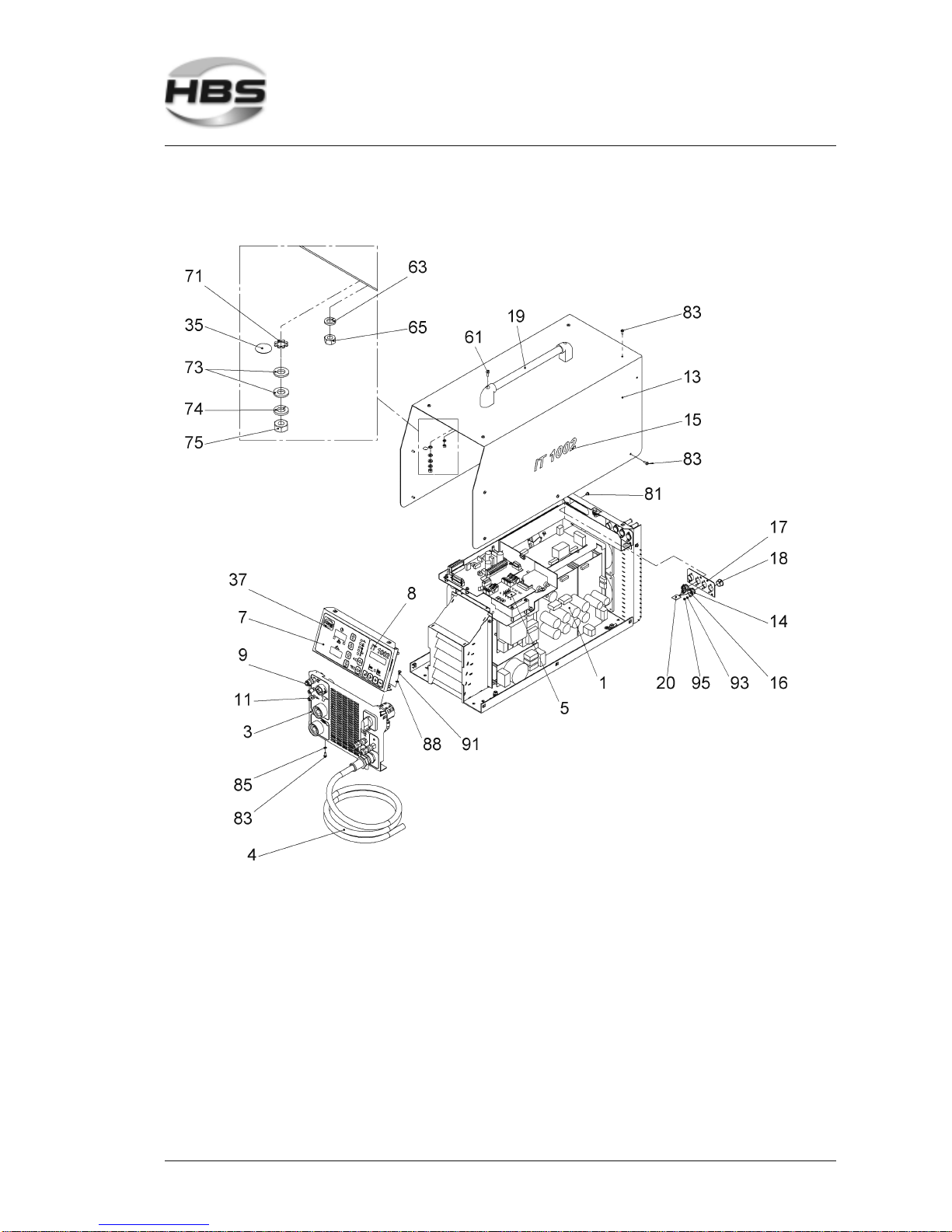
IT 1002 Order No BA 93-66-1206 Issue 03.11.08 61
Power unit IT type 1001 (93-66-1206)
8 Appendix
8.2 Spare Parts
Page 62

62 IT 1002 Order No BA 93-66-1206 Issue 03.11.08
Spare part list front plate complete IT 1002 (88-13-159)
Pos. Quantity Order No. Description
1 1 88-13-160 Operation plate
3 1 88-13-161 Front film operation plate
31 1 80-80-558 P.C. board
32 1 80-70-325 Connection cable
33 1 80-80-559 P.C. board
35 4 80-11-987 Distance sleeve
37 4 80-10-0174 Distance sleeve
39 8 80-11-415 Distance stud
41 2 80-11-111 Cage nut M4
43 1 80-11-121 Flat connection
45 1 80-90-386 Screw M6 x 14
47 1 80-90-197 Tooth lock washer A6
49 2 80-90-198 Washer 6 mm
51 1 80-90-147 Spring washer 6 mm
53 1 80-90-146 Nut M6
55 1 80-11-359 Conductor mark ground cable
8 Appendix
8.2 Spare Parts
Page 63
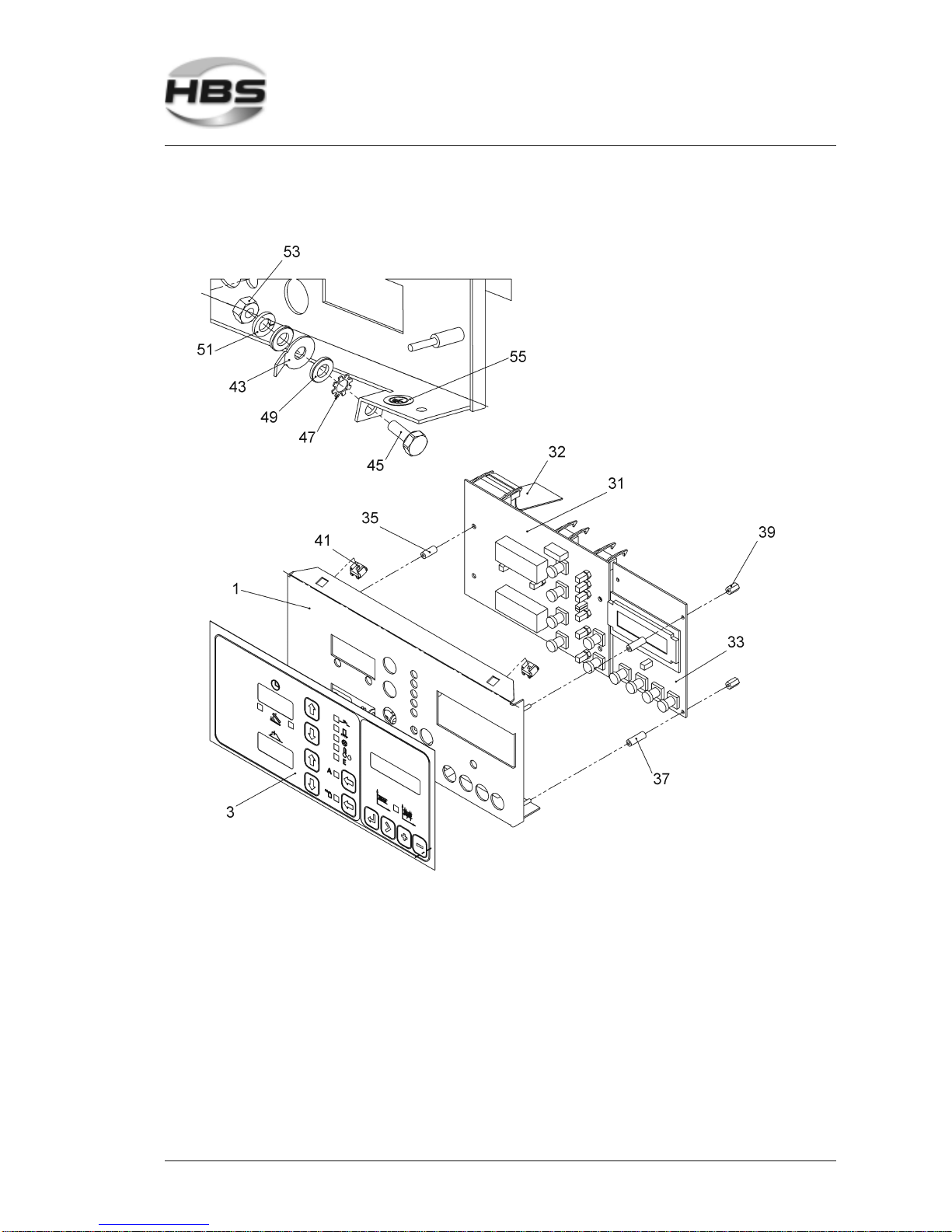
IT 1002 Order No BA 93-66-1206 Issue 03.11.08 63
Front plate complete IT 1002 (88-13-159)
8 Appendix
8.2 Spare Parts
Page 64

64 IT 1002 Order No BA 93-66-1206 Issue 03.11.08
Spare part list supply module complete IT 1002 (88-17-997)
Pos. Quantity Order No. Description
1 1 88-14-166 Support angular plate
3 1 88-13-178 Clamp angle
5 1 88-14-167 Cable channel
7 1 88-14-168 Angle
31 1 88-16-406 Transformer
33 1 80-80-597 P.C. board
35 1 80-50-927 Mains interference filter
37 1 80-80-557 P.C. board
39 1 80-56-041 Capacitor
41 1 80-57-332 Resistor L
43 1 80-40-066 Distance stud
51 4 80-11-989 Distance stud M4
55 1 80-11-670 Cable mounting
70 1 80-10-332 Adhesive clip
71 1 80-70-341 Connection cable
73 1 80-70-342 Connection cable
81 1 80-50-693 Plug 4 pin
85 1 80-50-640 Plug
90 1 80-10-0128 Solder tag M4
91 1 80-56-216 Capacitor noise suppression
101 4 80-90-388 Screw M4 x 6
105 9 80-90-191 Screw M4 x 8
107 1 80-90-504 Screw M8 x 14
109 8 80-90-164 Washer 4 mm
113 16 80-90-121 Spring washer 4 mm
116 5 80-90-110 Screw M4 x 8
118 1 80-90-184 Tooth lock washer A4
8 Appendix
8.2 Spare Parts
Page 65
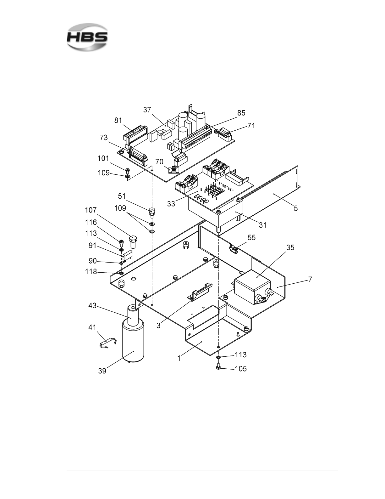
IT 1002 Order No BA 93-66-1206 Issue 03.11.08 65
Supply module complete IT 1002 (88-17-997)
8 Appendix
8.2 Spare Parts
Page 66

66 IT 1002 Order No BA 93-66-1206 Issue 03.11.08
Spare part list shielding gas module IT 1002 (88-13-167)
Pos. Quantity Order No. Description
100 1 80-10-145 Connector female
110 1 80-10-0916 Swivel connection
112 1 80-10-167 Screwing
115 1 80-10-240 Connector male
120 1 80-10-146 Solenoid valve
122 1 80-10-1073 Lock nut G1/4”
125 1 80-10-143 Connector female
0.26 m 80-10-182 Plastic hose
8 Appendix
8.2 Spare Parts
Page 67
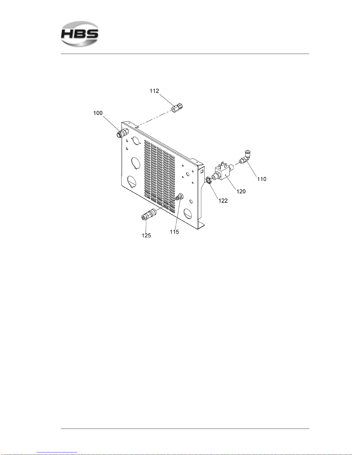
IT 1002 Order No BA 93-66-1206 Issue 03.11.08 67
Shielding gas module IT 1002 (88-13-167)
8 Appendix
8.2 Spare Parts
Page 68

68 IT 1002 Order No BA 93-66-1206 Issue 03.11.08
Spare part list terminal plate complete IT 1002 (88-18-013)
Pos. Quantity Order No. Description
1 1 88-18-014 Terminal plate
31 2 80-50-035 Mounting sleeve
33 1 80-10-0960 Screwed cable connection
35 1 80-11-567 Lock nut M25 x 1,5
41 1 80-50-480 Mains switch
44 1 80-10-0173 Clip-on ferrite
45 2 80-11-111 Cage nut M4
47 4 80-10-576 Flat connection
48 2 80-56-215 Capacitor noise suppression
49 1 80-11-121 Flat connection
61 1 80-11-359 Conductor mark ground cable
71 2 80-90-137 Screw M3 x 8
75 4 80-90-401 Screw M4 x 20
79 4 80-90-153 Nut M4
91 1 80-90-386 Screw M6 x 14
95 1 80-90-197 Tooth lock washer A6
99 2 80-90-198 Washer 6 mm
103 1 80-90-147 Spring washer 6 mm
107 1 80-90-146 Nut M6
8 Appendix
8.2 Spare Parts
Page 69
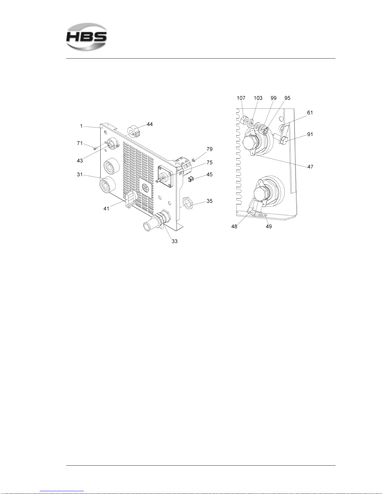
IT 1002 Order No BA 93-66-1206 Issue 03.11.08 69
Terminal plate complete IT 1002 (88-18-013)
8 Appendix
8.2 Spare Parts
Page 70

70 IT 1002 Order No BA 93-66-1206 Issue 03.11.08
Spare part list module adapter control IT 1002 (88-14-157)
Pos. Quantity Order No. Description
200 1 88-10-110 Valve carrier
205 1 80-10-188 Solenoid valve
210 1 80-10-189 Utensil socket
214 1.4 m 80-10-182 Plastic hose
215 1 80-10-024 Nipple
220 1 80-10-139 Connector male
225 1 80-10-143 Connector female
230 2 80-10-013 Connector female
231 2 80-10-656 O-ring 4 x 1,5 mm
235 2 80-10-140 Distance stud
240 2 80-10-138 Nipple
255 1 88-10-107 Cover plate four times
260 1 80-50-045 Control cable sleeve
265 1 80-50-176 Control cable sleeve
267 1 80-50-087 Control cable sleeve
270 1 80-10-785 Adhesive clip
275 1 80-70-340 Connection cable
285 1 80-10-161 Cap
290 6 80-90-190 Spring washer 3 mm
292 6 80-90-165 Nut M3
295 2 80-90-191 Screw M4 x 8
297 2 80-90-121 Spring washer 4 mm
300 2 80-90-164 Washer 4 mm
302 2 80-90-109 Screw M4 x 25
310 1 80-50-084 Control cable connector
312 1 80-50-172 Control cable connector
8 Appendix
8.2 Spare Parts
Page 71
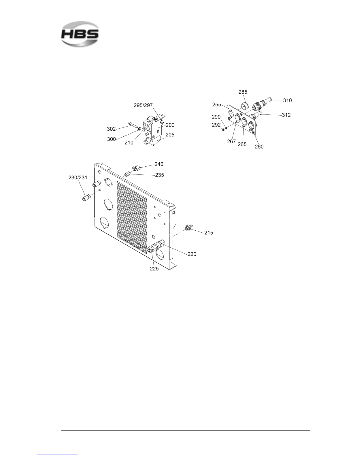
IT 1002 Order No BA 93-66-1206 Issue 03.11.08 71
Module adapter control IT 1002 (88-14-157)
8 Appendix
8.2 Spare Parts
Page 72

72 IT 1002 Order No BA 93-66-1206 Issue 03.11.08
Spare part list power element complete IT 1002 (88-17-929)
Pos. Quantity Order No. Description
1 1 88-14-158 Bottom plate
3 1 88-13-170 Rear wall
5 1 88-14-159 Screen angle plate
7 1 88-14-160 Intake channel
31 1 80-70-429 Power unit
39 4 80-10-203 Casing feet
41 10 80-11-111 Cage nut M4
43 3 80-11-121 Flat connection
51 1 80-11-358 Conductor mark PE-ground cable
53 3 80-11-359 Conductor mark ground cable
60 1 80-11-669 Wire protecting sleeve
70 2 80-10-050 Flat connection
71 4 80-90-173 Screw M4 x 10
72 1 80-90-404 Screw M4 x 25
73 4 80-90-191 Screw M4 x 8
75 2 80-90-261 Screw M4 x 10
77 4 80-90-319 Screw M4 x 8 black
81 3 80-90-184 Tooth lock washer A4
85 6 80-90-164 Washer 4 mm
89 8 80-90-121 Spring washer 4 mm
93 4 80-90-153 Nut M4
101 5 80-90-386 Screw M6 x 14
103 2 80-90-320 Screw M6 x 20
105 1 80-90-387 Screw M6 x 25
109 4 80-90-197 Tooth lock washer A6
113 8 80-90-198 Washer 6 mm
117 8 80-90-147 Spring washer 6 mm
121 7 80-90-146 Nut M6
8 Appendix
8.2 Spare Parts
Page 73
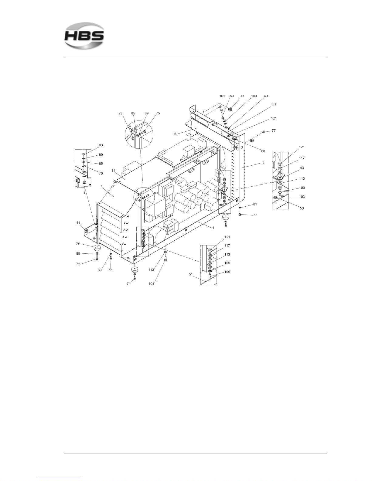
IT 1002 Order No BA 93-66-1206 Issue 03.11.08 73
Power element complete IT 1002 (88-17-929)
8 Appendix
8.2 Spare Parts
Page 74
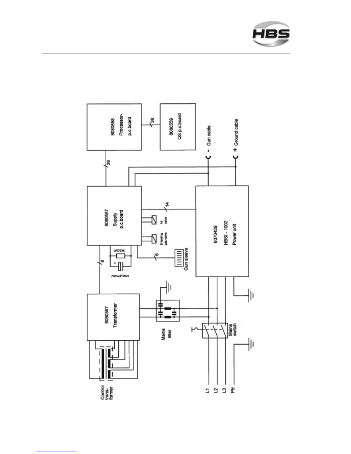
74 IT 1002 Order No BA 93-66-1206 Issue 03.11.08
8.3 Circuit Diagram
8 Appendix
8.3 Circuit Diagram
Page 75
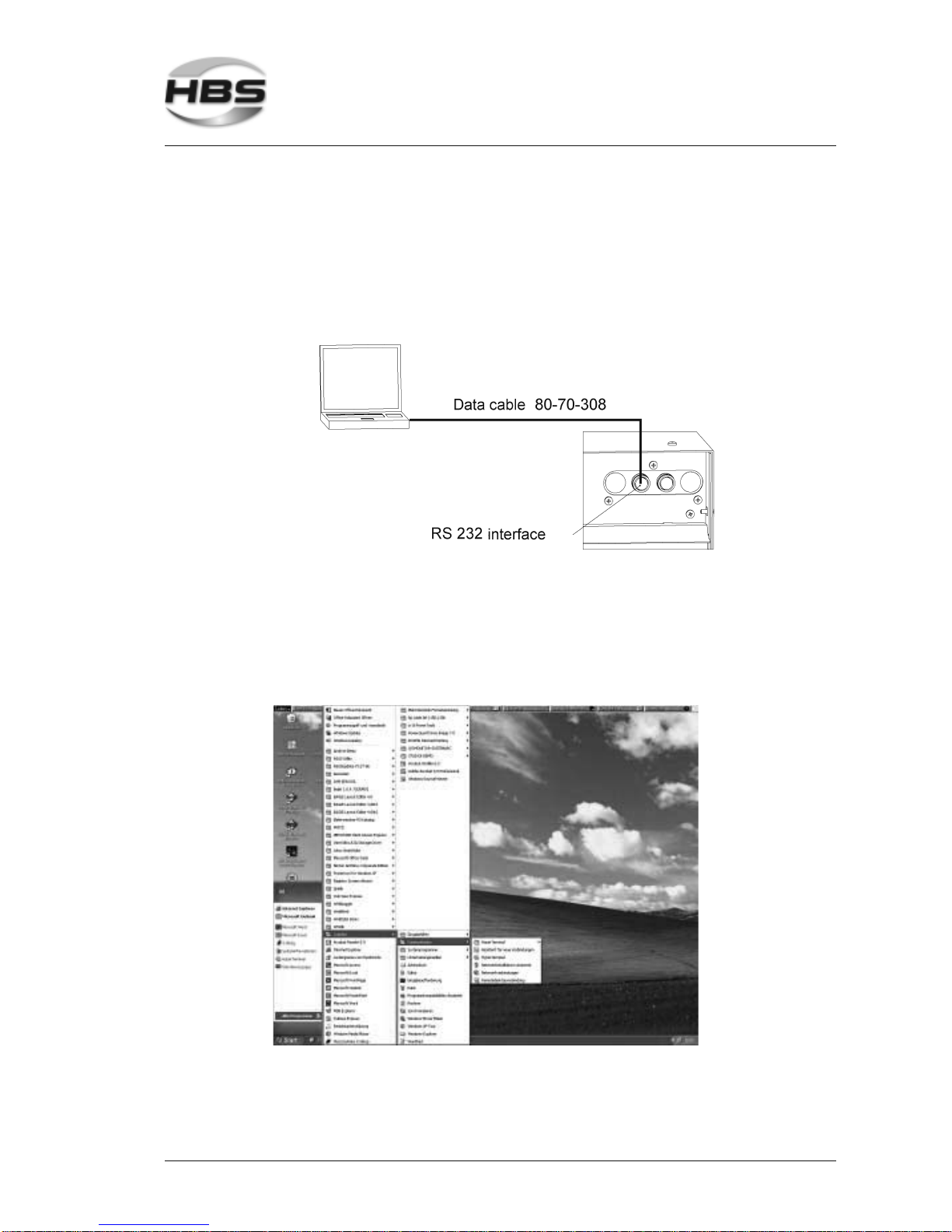
IT 1002 Order No BA 93-66-1206 Issue 03.11.08 75
8.4 Transmission of Recognized Data With Microsoft® Hyper Terminal
Switch on the controlling function of the output voltage (see section 5.6.7).
Any data can individually be processed in the window Microsoft® Hyper Terminal.
Link the data cable (HBS Order no. 80-70-308) to the serial sleeve of the power
unit and to the serial sleeve (com1 or com2) of a PC’s/Laptop.
Hyper Terminal call-up:
Start
ªPrograms
ªAccessories
ªCommunication
ªHyper Terminal
8 Appendix
8.4 Transmission of Recognized Data With Microsoft® Hyper Terminal
Page 76
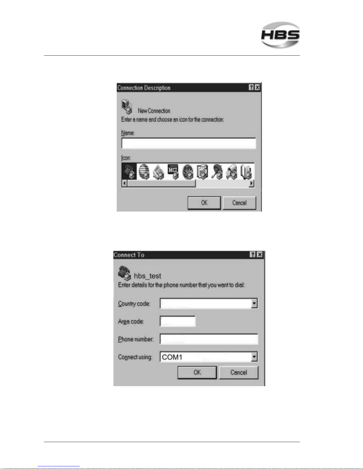
76 IT 1002 Order No BA 93-66-1206 Issue 03.11.08
Name the connection (e.g. the company name or a date - however without dots)
Select a symbol (any symbol)
Confirm with OK
Define the interface (com1 or com2 at the PC)
Confirm with OK
8 Appendix
8.4 Transmission of Recognized Data With Microsoft® Hyper Terminal
Page 77
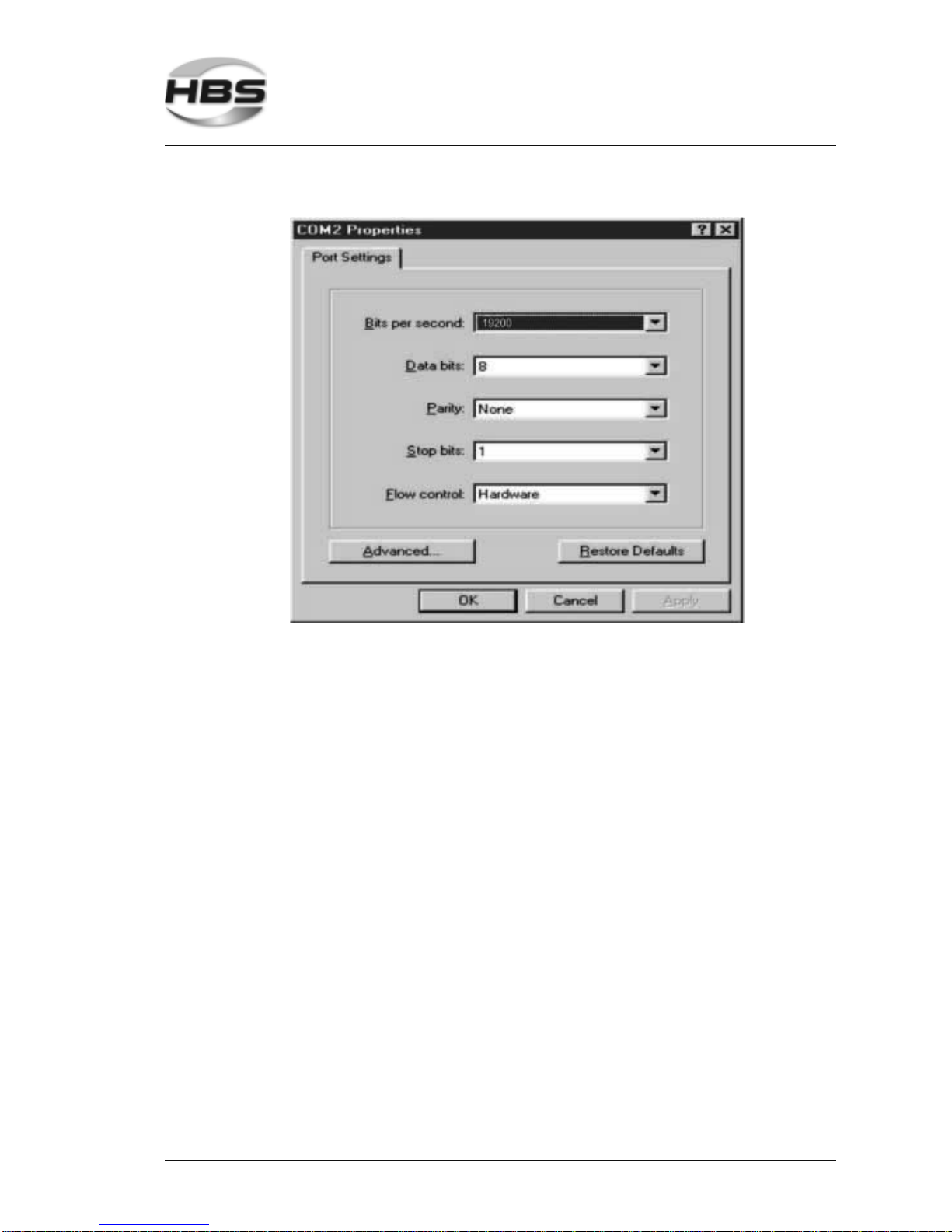
IT 1002 Order No BA 93-66-1206 Issue 03.11.08 77
Define the connection settings
Transmission rate: (Bits per second)
– CDM units 19200
– IT 1002 units 115200
Confirm with OK
8 Appendix
8.4 Transmission of Recognized Data With Microsoft® Hyper Terminal
Page 78
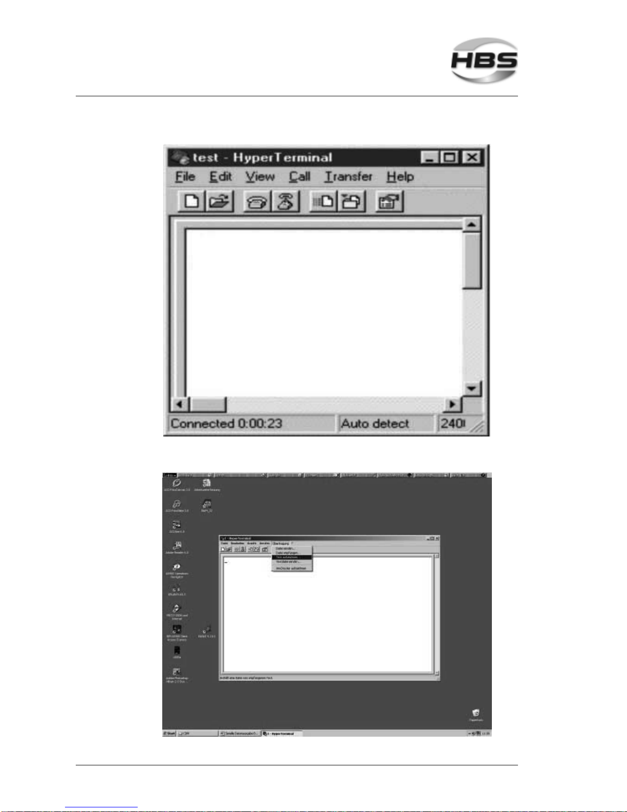
78 IT 1002 Order No BA 93-66-1206 Issue 03.11.08
Do not forget to save data
8 Appendix
8.4 Transmission of Recognized Data With Microsoft® Hyper Terminal
Page 79
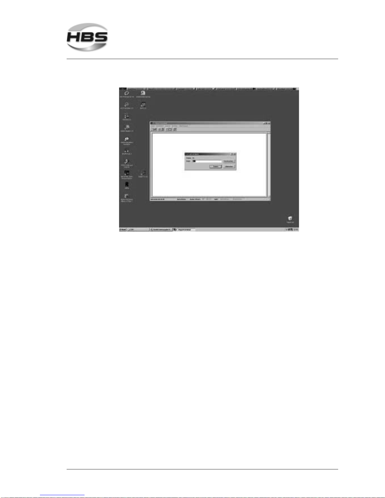
IT 1002 Order No BA 93-66-1206 Issue 03.11.08 79
Give a file name
Confirm with start
8 Appendix
8.4 Transmission of Recognized Data With Microsoft® Hyper Terminal
Page 80

80 IT 1002 Order No BA 93-66-1206 Issue 03.11.08
8.5 Environmentally Admissible Disposal
After repair of the power unit, dispose replaced parts in an environmentally
admissible way.
Used materials: - Steel
- Nonferrous metals (brass, copper)
- Plastics
- Aluminum
8 Appendix
8.5 Environmentally Admissible Disposal
Page 81

IT 1002 Order No BA 93-66-1206 Issue 03.11.08 81
Glossary
Arc: Electrical discharge at its own between two electrodes
under sufficiently high current. Whitish light is emitted.
The arc generates very high temperatures.
Automatic welding head: Device to weld welding elements
Capacitor: A component which serves as storage of electrical
charge
Power unit: Device to provide electrical energy for stud welding
Rectifier: Electric component transforming alternating current
into direct current
Stud feeder: Device for the automatic stud feeding of welding ele-
ments
Stud welding unit: Power unit inclusive welding gun
Thyristor: Electronic component, contactless switch, which will
let the current only pass through if a control pulse is
given to the gate (additional electrode)
Welding element: A component, like a stud, bolt, pin, which is welded to
the work piece
Welding gun: Device to weld welding elements
Welding parameters: Various settings on the gun as well as on the power
unit. For example: duration and strength of current
during welding process, charging voltage, spring force
of the welding gun.
Work piece: A component, like a sheet, tube, etc. to which the
welding element is fastened
Glossary
Page 82

82 IT 1002 Order No BA 93-66-1206 Issue 03.11.08
Regulations and Standards
The regulations and standards are recommendations and don`t purport to be
completely.
Standards, regulations Description
Stud welding (fundamentals)
DIN EN ISO 13918 Welding - Studs and ceramic ferrules for arc
stud welding
DIN EN ISO 14555 Welding - Arc stud welding of metallic materials
DIN EN 1418 Welding personnel - Approval testing of welding
operators for fusion welding and resistance weld
setters for fully mechanized and automatic
welding of metallic materials
DVS 0901 Stud welding method for metals - Survey
DVS 0902 Arc stud welding
DVS 0903 Capacitor discharge welding with tip ignition
DVS 0904 Tips - Arc stud welding
DVS 2927 Resistor projection welding and Arc welding of
one-sided thick plastics coated thin metal
sheets
Stud welding (general)
DIN EN ISO 4063 Welding and allied processes - Nomenclature of
processes and reference numbers
DIN ISO 857-1 Welding and allied processes - Vocabulary -
Part 1: Metal welding processes
DIN EN ISO 14175 Welding consumables - Shielding gases for
fusion welding and allied processes
DIN EN 764-1 Pressure equipment - Part 1: Terminology -
Pressure, temperature, volume, nominal width
DIN EN 6947 Welds - Working positions - Definitions of
angles of slope and rotation
DIN 1910 Welding
Regulations and Standards
Page 83

IT 1002 Order No BA 93-66-1206 Issue 03.11.08 83
Machine safety
73/23/EWG Electrical equipment designed for use within
certain voltage limits
2004/108/EG EMC-Guidelines
98/37/EG Machine guidelines
DIN EN 60204-1 Safety of machinery - Electrical equipment of
machines - Part 1: General requirements
DIN EN 60529 Degrees of protection provided by enclosures (IP
code)
DIN EN 60974-1 Arc welding equipment - Part 1: Welding power
sources
DIN EN 60974-10 Electromagnetic compatibility (EMC); Arc
welding equipment - Part 10: Requirements
Personal safety and accident prevention
DIN EN ISO 20345 Personal protective equipment:
Safety footwear
DIN EN 12477 Protective gloves for welders
DIN EN 166 Personal eye-protection - Specifications
DIN EN 352-1 Hearing protectors - General requirements -
Part 1: Ear-muffs
BGV A1 Safety rules „Principles of prevention“
BGV A3 Accident prevention regulation „Electrical
equipment and operating material“
BGV B3 Safety rules “Noise”
BGV B11 Safety rules “EMC”
BGV D1 Safety rules - welding, cutting and similar
processes
Please note that in your country additional standards and safety
conditions (especially rules for accident prevention) may differ
from the standards mentioned in this operating manual.
Regulations and Standards
Page 84
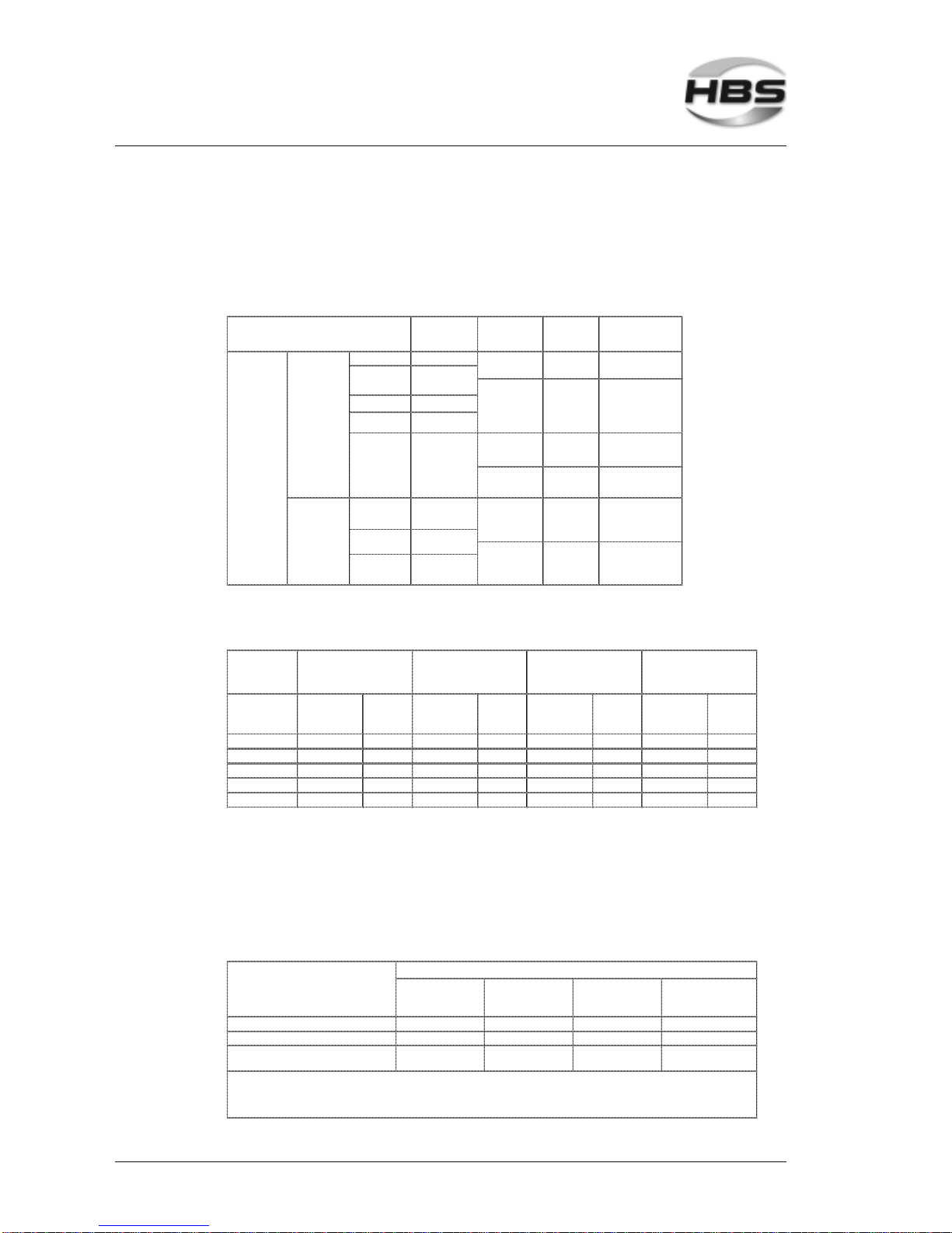
84 IT 1002 Order No BA 93-66-1206 Issue 03.11.08
Further Instructions
Welding elements, abbreviations, materials, standards, mechanical
properties to actual standards
Abbr eviations f or
studs (ceramic
ferrules)
Material Norm
Mec ha ni ca l
characteristic s
Threaded stud PD (PF)
Pin w it h
internal thread
ID (U F)
Mild steel
(S235J2G3
+ C450)
ISO/TR 15608
Rm ≥ 400 N/mm
2
ReH ≥ 235 N/mm
2
A5 ≥ 15%
1.4301/03
(A2-50)
EN 10088-1
Rm ≥ 500 - 780 N/mm
2
Rp0,2 ≥ 350 N/mm
2
A5 ≥ 25%
Threaded stud
w ith flange
PS
Pin w ith internal
thread and
flange
IS
Mild steel (4.8
1)
) ISO 898-1 see ISO 898-1
Mild steel (4.8
1)
)
copper plated
1.4301/03
(A2-50)
EN ISO
3506-1
see ISO 3506-1
Stud types
Short cycle
welding
with
draw n arc
Drawn ar c
welding
with
ceramic ferrule
(CF)
or s hielding gas
(SG)
Hea d s tud
Stud
w elding
with
drawn arc
(DS)
Pin
Pin
w ith flange
UD (UF)
Th
readed stu
d
w ith reduc ed
shaft
RD (RF)
SD (UF)
US
1.4301/03
(A2-50)
EN ISO
3506-1
see ISO 3506-1
ISO 898-1 see ISO 898- 1
Further materials on request
1)
weldable
Prestress at installation (tie load) and torque
Threaded stud
Pr estres s at
installation
(kN)
Torque
(Nm)
Pr estres s at
ins tallatio n
(kN)
Torque
(Nm)
Prestress at
inst allation
(kN)
Torque
(Nm)
Pr estres s at
ins tallatio n
(kN)
Torque
(Nm)
M 6 4,3 6,1 2,7 3,8 2,2 3,1 3,2 4,5
M 8 8,0 15,0 4,9 9,5 4,0 7,5 6,0 11,0
M 10 13,0 30,0 7,8 19,0
M 12 19,0 53,0 12,0 33,0
M 16 35,0 135,0 22,0 82,0
Steel (4.8
1)
)
µ = 0,18
R
p0,2
= 340 N/mm
2
1.4301/03 (A 2-50)
µ = 0,18
R
p0,2
= 210 N/mm
2
AlMg3 (F23)
µ = 0,18
R
p0,2
= 170 N/mm
2
CuZn37 (Ms63)
µ = 0,18
R
p0,2
= 250 N/mm
2
Values correspond with actual standards
1)
weldable
All given values are leads for minimum tensile strength and minimum torque of a weld without permanent deformation
of parts to be joined. Parts to be joined must have sufficient wall thickness. Values apply for cold rolled threaded studs
with standard thread without surface protection and without thread lubrication. Throughout the entire stud length, at
least the stressed cross section must be present. Values apply for indicated yield strengths.
Material combinations
according to the actual standards (select stud material in a way that material of the
same kind is welded).
ISO/TR 15608
Groups
1 and 2.1
ISO/TR 15608
Groups
2.2, 3 to 6
ISO/TR 15608
Groups
8 and 10
ISO/TR 15608
Groups
21 and 22
Steel (S235) 4.8
1)
16Mo3
abb --
1.4301/03, 1.4401/04, 1 .4541,1.4571
b/a b a -EN A W-AlMg3/EN AW-5754
EN A W-AlMg5/EN AW-5019
-- -- -- b
Exemplific ation of w elding su itability
-- non w e
ldabl
e
a w e
ll
suited for any application, e.g. pow er trans mission
b
suitable, limitations with pow er transmission
Base material
Stud material
Weldability tests of other material combinations upon request.
1)
weldable
Further Instructions
Page 85

IT 1002 Order No BA 93-66-1206 Issue 03.11.08 85
Guarantee Clauses
Please refer to the current “General Terms and Conditions” for the guarantee clauses.
We are not liable for malfunctions which are caused by
– normal wear,
– improper use,
– non-observing the operating manual,
– transport damages.
Any guarantee claim will be cancelled if repair operations are carried out by unauthorized
persons.
Warning: Unauthorized interference with the stud welding unit
as well as unauthorized alteration of the stud welding unit are
prohibited and result in complete cancellation of any guarantee
and liability claims against HBS.
Please fill in the serial number:
Serial number automatic welding head: ..............................................
Serial number power unit: ..............................................
Serial number stud feeder: ..............................................
Serial number welding gun: ..............................................
Please indicate the serial numbers in case of enquiries or when ordering spare parts.
Guarantee Clauses
Page 86

86 IT 1002 Order No BA 93-66-1206 Issue 03.11.08
Confirmation
Herewith I confirm that I have read and understand the present operating manual
completely.
Date Name
________________ ___________________________________
________________ ___________________________________
________________ ___________________________________
________________ ___________________________________
________________ ___________________________________
________________ ___________________________________
________________ ___________________________________
________________ ___________________________________
________________ ___________________________________
________________ ___________________________________
________________ ___________________________________
________________ ___________________________________
________________ ___________________________________
________________ ___________________________________
________________ ___________________________________
________________ ___________________________________
________________ ___________________________________
________________ ___________________________________
Confirmation
Page 87

IT 1002 Order No BA 93-66-1206 Issue 03.11.08 87
Feedback
HBS Bolzenschweiss-Systeme Sender:
GmbH & Co. KG __________________________
Felix-Wankel-Strasse 18 __________________________
85221 Dachau / Germany __________________________
Postfach 13 46 __________________________
85203 Dachau / Germany __________________________
Product description __________________________
Serial number __________________________
My opinion/criticism/complaints/indication of malfunction:
Date and signature ___________________________________________
Feedback
Page 88
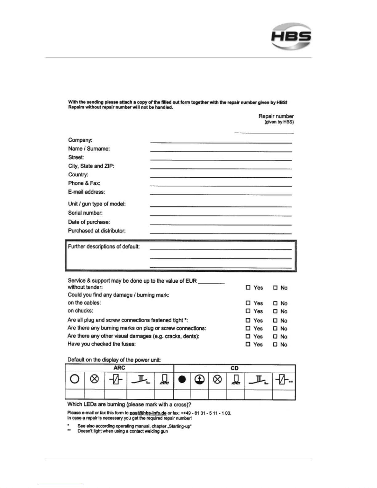
88 IT 1002 Order No BA 93-66-1206 Issue 03.11.08
Service & Support
Service & Support
Page 89

IT 1002 Order No BA 93-66-1206 Issue 03.11.08 89
Index
A
accident prevention ........................ 12, 25
accident prevention regulations ............ 16
accidents ............................................ 26
accompanying documents ................... 13
adjusting the controls .......................... 38
adjusting the date ................................ 41
adjusting the time ................................ 42
air connector ....................................... 44
airborne particles ................................. 16
arc ....................................................... 81
arc blow effect ..................................... 51
arrow keys .....................................36, 37
articles, combustible ........................... 16
assembly .............................................. 9
automatic welding head ....................... 81
automatic welding head KAH 412 ........ 46
automatic welding mode ...................... 44
B
bang ....................................... 17, 26, 43
bending device with inserts .................. 49
bending test ........................................ 49
blow time ............................................. 38
blow-up ................................................ 25
C
capacitor ............................................. 81
care and maintenance ......................... 10
ceramic ferrule/ring .............................. 29
charging supervision ............................ 46
circuit diagram ..................................... 74
cold formed process ............................ 53
company specific
maintenance instruction ................. 9
company specific work order ................. 9
components of the power unit .............. 22
compressed air connection .................. 21
compressed air supply ........................ 21
confirmation ......................................... 86
confirmation, operator sign .................... 9
connect with feeding unit ..................... 45
connecting the welding gun ................. 18
contact ................................................ 46
control cable connector ....................... 18
cooling fan ........................................... 59
corrective actions ................................ 49
cover ................................................... 58
cross-slotted screwdriver ..................... 57
D
data cable ........................................... 75
defective cables ................................... 32
delivery .......................................... 10, 15
display ................................................ 23
disposal ............................................... 56
disposal, environmentally admissible ... 80
distance device .................................... 43
DVS regulations .................................. 43
E
ear protection ................................. 9, 25
electrical shock, risk of ....................... 21
electrical voltage ..................... 11, 14, 24
electrode mode .................................... 38
electromagnetic fields ........................... 11
entire plug connection, destroying ....... 18
external welding start .......................... 45
F
fault recognition ............................. 49, 52
feedback ............................................. 87
feeding unit .......................................... 21
file name ............................................. 79
fire extinguisher ............................. 16, 25
fire risk ................................................ 25
flash ....................................... 17, 26, 43
fluids, ingress of .................................. 56
foreign bodies, ingress of ..................... 56
fume extraction .................................... 25
function ............................................... 22
functional principle ............................... 10
further instructions ............................... 84
fuse rating ........................................... 17
G
gas pre-flow time ................................. 37
general .................................................. 9
general safety instructions ................... 12
glossary .............................................. 81
gloves .................................................... 9
ground cable .................................. 19, 58
ground clamps ..................................... 19
ground connection ............................... 19
guarantee claims .................... 12, 26, 85
Index
Page 90

90 IT 1002 Order No BA 93-66-1206 Issue 03.11.08
guarantee clauses ............................... 85
guide ................................................... 10
H
headgear, protective ............................. 25
heat built-up ........................................ 16
high-strength welds ............................. 32
hollow parts, welding on ...................... 25
hyper terminal ............................... 47, 75
I
intended use ........................................ 12
K
keyboard ............................................. 23
L
laptop PC ............................................ 75
LCD display ......................................... 35
liability, any ............................ 12, 26, 85
library mode ........................................ 37
liquid spatters ...................................... 43
liquids, combustible ............................. 16
lot ........................................................ 53
M
magnetic fields .............................. 16, 26
mains switch ....................................... 34
maintenance ........................................ 57
maintenance instruction
for your company ........................... 9
malfunction ..................................... 9, 52
markings ............................................. 14
material combinations ................... 33, 84
material of the welding element ........... 32
material of the workpiece ..................... 32
material separation,
environmentally correct ................. 56
metal spatters ..................................... 25
Microsoft® hyper terminal ................... 75
minimum flow rate ............................... 20
N
non-combustible clothes ...................... 25
O
OK/ERR .............................................. 47
operating manual ............................ 9, 15
operating manual, storage of ................. 9
operation, improper .............................. 43
operators ............................................... 9
order number ................................. 15, 60
ordering spare parts ............................. 85
P
pace maker ............................ 11, 17, 26
packaging ............................................ 13
PC/laptop ............................................ 75
personal injury ......................................11
personnel, properly instructed, qualified ... 9
personnel, qualified ................................ 9
pipes, welding to ................................. 32
place of operation ................................ 12
power unit ...................................... 22, 81
power unit, switching on ...................... 34
prestress at installation .................33, 84
primary power supply .......................... 17
primary voltage .................................... 17
production ............................................. 9
protective apron ................................... 25
protective equipment ......................17, 26
protective equipment, personal .............. 9
protective gloves .................................. 25
protective goggles .................................. 9
punched plates .................................... 32
punched plates, welding to .................. 32
R
rectifier ................................................ 81
recycling ............................................. 80
REFERENCE MODE .......................... 36
reference mode entry ........................... 40
reference mode welding ....................... 39
regulations ........................................... 82
repair ................................................... 80
requirements of workplace ............. 16, 32
risk of material damage ........................11
room adequately ventilated .................. 25
rooms exposed to risk of explosion ..... 16
RS-232 interface .................................. 47
S
safety goggles ..................................... 25
safety instructions .................... 9, 24, 57
safety symbols .................................... 14
SELECT LANGUAGE .......................... 36
serial number ...................................... 85
Index
Page 91

IT 1002 Order No BA 93-66-1206 Issue 03.11.08 91
service ................................................... 9
service & support ................................. 88
service technician .................................. 9
SET DATE ........................................... 36
SET TIME ............................................ 36
set-up .................................................... 9
shielding gas bottle ............................. 20
shielding gas connection ..................... 20
shielding gas module ........................... 66
shoes .................................................... 9
spare part list ...................................... 60
spare parts, ordering of .................. 60, 85
special welding elements ..................... 55
standards ............................................ 82
standards, actual ........................... 12, 43
starting-up ..................................... 10, 16
stop with red ........................................ 40
storage ................................................ 13
stud feeder .......................................... 81
stud feeding, automatic ....................... 44
stud welding, functional principle ......... 27
stud welding procedure ........................ 24
stud welding process ........................... 10
stud welding unit ................................. 81
stud welding, variants .......................... 28
surface of welding element .................. 49
surface, workpiece .............................. 49
switching off, temporary ....................... 56
switching off the power unit ............ 10, 56
T
technical data ................................ 10, 59
test welding ......................................... 32
threat to life ......................................... 10
thyristor ............................................... 81
tolerance ............................................. 39
tools .................................................... 57
torque ............................................33, 84
training according to current standards .... 9
transmission rate ................................. 77
transportation ................................. 9, 13
transportation, packaging, storage ....... 13
type plate ...................................... 14, 17
U
unauthorized use ................................... 9
user qualification, required ..................... 9
V
vapors, toxic ........................................ 16
visual inspection .................................. 48
W
weld, checking the quality of the .......... 48
welding, automatic mode ..................... 44
welding element .................................. 81
welding elements .................... 12, 32, 53
welding elements, lot of ....................... 32
welding gun ...................................12, 81
welding gun cables .............................. 18
welding gun support ............................. 43
welding head ....................................... 44
welding parameters ....................... 43, 81
welding parameters, determination ...... 32
welding preparation .............................. 32
welding procedure ................................ 43
welding process .................................. 10
welding spatters .................................. 43
work piece ........................................... 81
working place, change of ..................... 21
Index
Page 92

92 IT 1002 Order No BA 93-66-1206 Issue 03.11.08
Page 93

Page 94

HBS Bolzenschweiss-Systeme GmbH & Co. KG • Felix-Wankel-Strasse 18 • 85221 Dachau / Germany
Phone +49 (0) 8131 511-0 • Fax +49 (0) 8131 511-100 • E-mail [email protected]
www.hbs-info.com
 Loading...