

Page 1
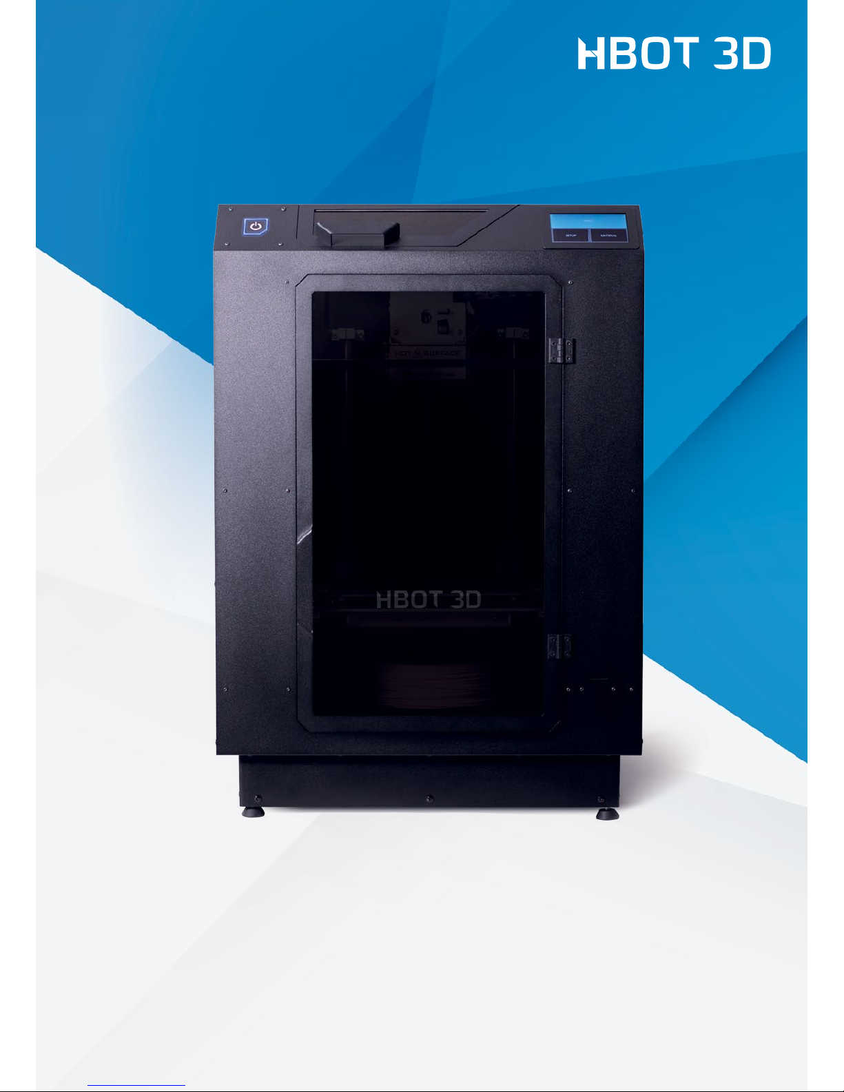
Operating Manual
HBOT 3D F300
3D printer for industrial applications
OM-F300-EN-01-18
Page 2

2
Table of content
1. Preface 3
1.1 Conventions used in this operating manual 3
1.2 Copyright 3
1.3 Trademarks used in this manual 3
1.4 Manufacturer’s warranty and responsibility 4
1.5 Intended use of the device 4
2. Operational safety 5
2.1 General principles 5
2.2 Electrical hazards 5
2.3 Risk of injury and burn 6
2.4 Noise emission 6
2.5 Safety marking on device 6
3. Device description 7
3.1 Essential components 7
3.2 Extruder and carriage assembly 8
3.3 Extruder assembly 8
3.4 Control panel 9
3.5 Technical specication 9
3.6 Device identication 10
4. Printer installation 11
4.1 Package content 11
4.2 Removing the transport locks 12
4.3 Selecting location 12
4.4 Leveling 13
4.5 Power supply connection 13
4.6 Connection to emergency supply 13
4.7 Initial commissioning 14
5. Description of use 18
5.1 Preparing the build platform 18
5.2 Storing materials 18
5.3 Loading material 18
5.4 Removing material 18
5.5 Changing material 19
5.6 Replenishing material 20
5.7 Starting a print 20
5.8 Pausing and resuming print 21
5.9 Aborting print 21
5.10 Finishing print 21
5.11 Removing print from the build platform 21
5.12 Removing support structures 22
5.13 Nozzle replacement 22
6. Preparing les 24
6.1 Installation of Simplify 3D 24
6.2 Graphical user interface 25
6.3 Importing material congurations 25
6.4 Modifying the default settings 26
6.5 Importing models and orientation 26
6.6 Conguring printing parameters 27
6.7 Displaying print preview and exporting control commands 28
6.8 Editing support structures 28
6.9 Advanced print parameters 29
6.10 Saving a project 33
6.11 Additional software options 33
6.12 Using SD card and USB port 34
7. Maintenance and operation 35
7.1 Recommended maintenance operations 35
Page 3

1. Preface
3
Preface
This Manual contains relevant information regarding installation, operation and maintenance of your device. Your are kindly requested
to carefully read this Operating Manual before commissioning your device. Strict compliance with the notes contained herein will
prevent the misuse and allow you to take full advantage of the features and functions of your printer. Store this Operating Manual
so that it is always available to you.
The device, before leaving the manufacturing plant is carefully checked before packaging for safety and functionality on our testing
facilities. As a remainder of this control may be the presence of lament inside the nozzle or on its outer surface.
The 3D Printers Team is constantly working on the development of their products and reserves the right to make changes without prior
notice. You can download the latest version of the Operating Manual from manufacturer’s website at www.hbot3d.com.
1.1. CONVENTIONS USED IN THIS OPERATING MANUAL
Below you will nd explanation of conventions used in this Manual.
Important information, instruction which must absolutely be followed or dangers or dangerous actions which may
lead to serious personal injuries and/or damage to property
Tip, important information
1.2 COPYRIGHT
@ All rights reserved. The contents of the manual, logos, pictures, photos, trademarks as well as other its elements are subject
to copyright of 3D Printers sp. z o.o. in Wrocław
The User has the right to print and store this Operating Manual, as well as to save and retrieve the computer le with a copy hereof in
computer’s memory or other electronic equipment designed to receive and process digital content, for the purposes of operating and
maintaining the device.
Without express permission from 3D Printers sp. z o.o. duplicating, reproducing, adapting, translating, copying, processing,
promulgating, selling, or distributing this Operating Manual (including portions hereof) is prohibited.
1.3 TRADEMARKS USED IN THIS MANUAL
DimaFix – is a registered trademark of DIMA 3D Printers
Simplify 3D – is a registered trademark of SIMPLIFY3D LLC
Microsoft, Windows, Windows NT, Windows Server and Windows Vista 64, Windows 7, Windows 8, Windows 8.1 and Windows 10
– are registered trademarks of Microsoft Corporation
Mac and macOS – are registered trademarks of Apple Inc.
Linux – is a registered trademark of Linus Torvalds
Any other products referred to in the Manual may be registered trademarks of their respective owners.
3D Printers sp. z o. o. shall not claim any right to the said trademarks.
Page 4

1. Preface
4
1.4 MANUFACTURER’S WARRANTY AND RESPONSIBILITY
3D Printers sp. z o. o. grants a 12-month guarantee regarding the device on the basis of a Warranty Card, unless otherwise provided
for in the contract with the buyer, or other documents issued by the manufacturer.
3D Printers sp. z o. o. shall not be liable for damages arising out of the use, storage, modication, abuse and transportation of the
device not conforming to this Manual.
3D Printers sp. z o. o. shall not be liable for damages arising out of the use of additional accessories, consumables, ancillary equipment,
computer software and other items or additions which may accompany the device, or be consumed by the device during its usage,
operation, maintenance or transportation, but which are not manufactured by 3D Printers sp. z o. o.
1.5 INTENDED USE OF THE DEVICE
HBOT 3D F300 is designed to materialise different models directly from three-dimensional CAD documentation, without using
machining or any additional tools. The possibilities of additive technologies, also known as “3D printing”, are invaluable when
designing new products. The HBOT 3D F300 was created for industry, to optimize production processes mostly by reducing its time
and costs. FFF (Fused Filament Fabrication) technology works with a wide range of plastics to build up for the construction of threedimensional objects.
Areas of application
prototypes tools small-scale
production
moulding forms nal products production line
maintenance
Key industries
automotive aerospace electronic military manufacturing foundries
Action scheme
preparing 3D cad model
export to .stl creating .gcode in provided Simplify 3D software transfering the .gcode le to
the printer’s sd card lament insertion starting the printing process.
This product is not intended for use in life support, critical care, medical, safety equipment, or similar applications where product failure
could result in loss of life or personal or physical harm, or any military or defence application, or any governmental procurement to
which special terms or provisions may apply.
Page 5

2. Operational Safety
5
2.1 GENERAL PRINCIPLES
Basic safety precautions must me followed at all times during device operation. Glasses and protective gloves accompanying the
device must always be worn when carrying out manual operations at the device. Any and all operating and handling activities must be
performed in accordance with this Manual, and using only tools recommended by the manufacturer.
The device is a sophisticated manufacturing tool, and therefore may only be operated by authorized and properly
trained personnel.
The device is not intended for use by children under 13 years of age, or by persons of impaired manual, motor,
or psychomotor capacities.
The device must be stored out of the reach of the children and animals.
Whenever a device malfunction is found, cut off power supply to the device and immediately contact the Technical
Department of the manufacturer.
Do not make any modication and change to the device by yourself. Otherwise you will loose the manufacturer’s
guarantee, or a personal injury or damage to the device may result.
During the printing process do not leave the device unattended.
In order to prevent potential malfunction, periodically check the condition and operating status of the device.
Regularly check the wear status of wearing parts of the device. For detailed device maintenance recommendations
refer the chapter “MAINTENANCE AND OPERATION”
2.2 ELECTRICAL HAZARDS
HBOT 3D F300 Printers have been manufactured as a Class I appliance in terms of protection against electric shock and tested for
conformance to LVD and EMC Directives.
Before connecting the printer to a power outlet ensure that the available power supply voltage meets the
specications for the device. For power supply specications, see the device nameplate on the back of the device.
Avoid overloading the power outlet the printer is plugged into.
The device must be properly grounded. Always connect the device to a power supply mains with a fully functional
protective earthing conductor PE.
Use only original power cord. Do not damage, cut or make any repairs to it. Damaged cord must immediately be
replaced with a new one supplied by the manufacturer.
Cleaning, repairs or maintenance must be made after power has been cut off to the printer. Never expose the
device to contact with water or moisture.
2. Operational Safety
Page 6

2. Operational Safety
6
2.3 RISK OF INJURY AND BURN
To ensure the highest degree of safety and avoid personal injuries, always wear protective glasses and gloves and follow the
instructions. To ensure the highest degree of safety and avoid personal injuries, always wear protective glasses and gloves and follow
the instructions.
Touching the print head during operation is prohibited. Contact with hot print head may result in severe
burns.
Do not touch hot printing platform during device operation. Contact with hot printing platform may result in
severe burns.
Do not put parts of your body, or mechanical parts into operating fans, also prevent your hair or loose parts
of your clothing from getting into moving parts of the printer.
For safety reasons the top and front door must be closed during the printing process.
Keep a safe distance when the device is in operation. Direct contact with moving and hot parts may result in
a bodily injury to the operator.
The nished print should be removed using protective gloves, the scraper provided for this purpose and
after the build platform has been removed from the device.
In the event of burn or bodily injury, follow the general rules of rst aid.
2.4 NOISE EMISSION
The sound pressure level at the workplace where the HBOT3D F300 printer is operated does not exceed 70 dB (A).
2.5 SAFETY MARKING ON DEVICE
The device has “HOT SURFACE” warning labels on relevant parts of the device. Always exercise special care when handling hot parts.
Wearing protective gloves is obligatory. Temperature of some components may reach 300°C.
Page 7
Drukarka 3D
Model: HBOT 3D F300
S/N: XXX/YYYY/123456
Rok produkcji | Production year: YYYY
ly voltage: 100-240V ~ 500W 50-60Hz
zy 230V | Nominal current at 230V: In = 2.0A
Spełniane normy / Complaints with: EN 61000-6-3:2007, EN 61000-6-1:2007
3D Printers sp. z o.o.
Aleja Ludomira Różyckiego 1C/4
51-608 Wrocław
www.HBOT3D.com
Top door
Stand-by button
Front door
Chamber fan
air intlet
Filament holder
Leveling feet
USB socket
SD Card slot
Build platform
Chamber fan
air outlet
Touch
Control Panel
Print head
Lead screw
Bowden tube
entry
Guide
rods
Power
switch
Nameplate
Power cord
connection
3. Device Description
7
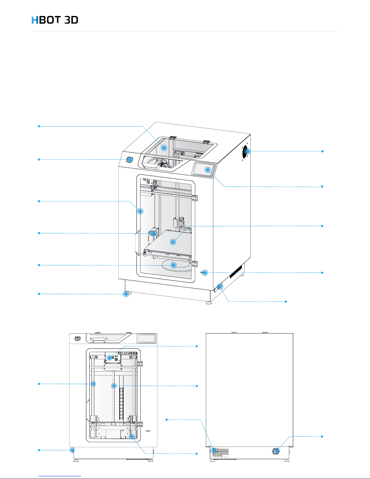
Before operating the device be sure to familiarize yourself with all device parts. Your failure to familiarize yourself with their locations
and functions may result in misoperation of the device and/or its damage due to user’s fault.
3.1 ESSENTIAL COMPONENTS
3. Device Description
Page 8
Extruder Case
Extruder block
Gear motor
Hotend
Nozzle
Cooling channels
Carriage cover
Extruder & Hotend assembly
Extruder assembly
Heater block
Carriage
Bearings
Bowden
tube
Drive gear
Extruder lever
Nozzle
Cooling channels
Extruder
fan
Guide rods
HTD Belt
Carriage cover
Carriage
Bearing
Extruder case
Bowden push-fit connector
Extruder Case
Extruder block
Gear motor
Hotend
Nozzle
Cooling channels
Carriage cover
Extruder & Hotend assembly
Extruder assembly
Heater block
Carriage
Bearings
3. Device Description
8
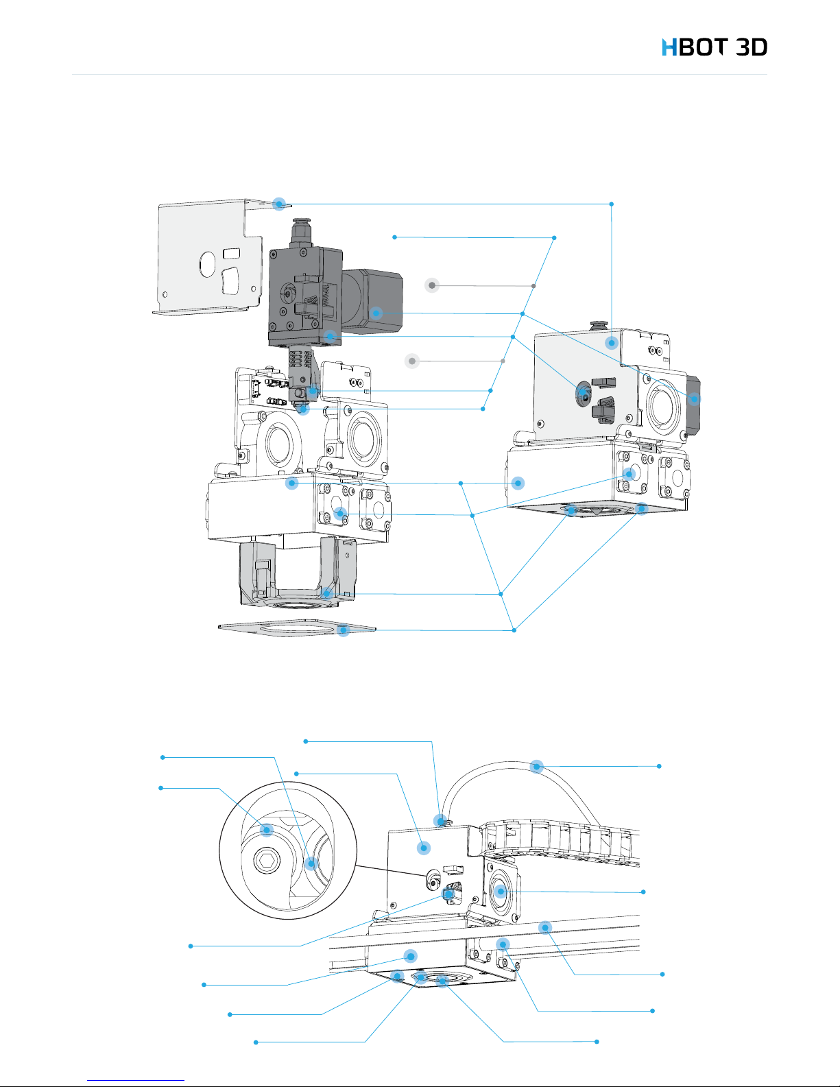
3.2 EXTRUDER AND CARRIAGE ASSEMBLY
3.3 EXTRUDER ASSEMBLY
Page 9
3. Device Description
9
3.4 CONTROL PANEL
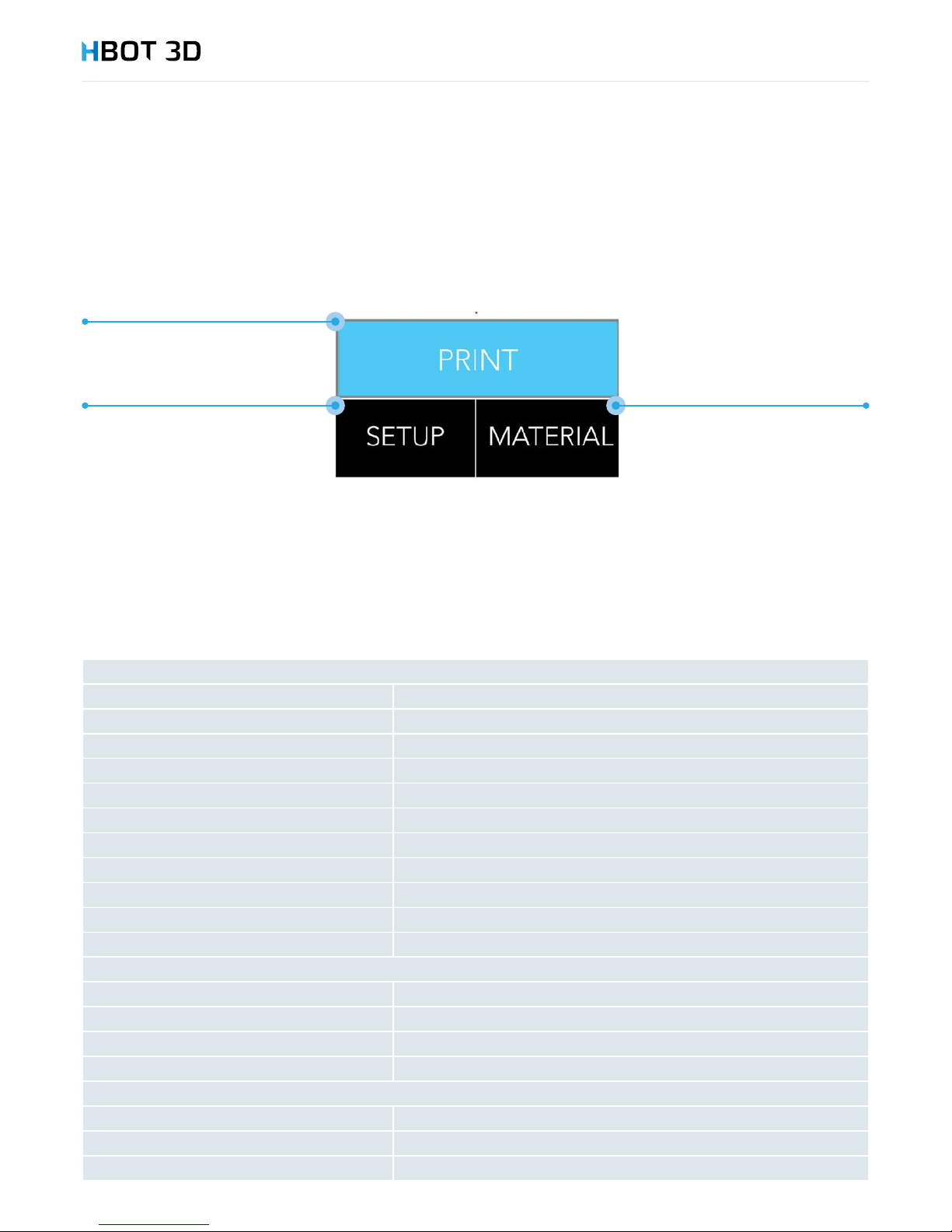
The device is equipped with a capacitive touch LCD panel for operating the printer. Below you will nd a diagram of available screens
and functions supported by the display.
3.5 TECHNICAL SPECIFICATION
General information
Technology FFF
Build volume 300 x 300 x 300 mm
Build chamber Closed, with forced ventilation
Build platform Heated, borosilicate glass covered with kapton foil
Hotend positioning Automatic
Build platform leveling Semi-automatic
Extruder Single
Maximum hotbed temperature 120°C
Maximum hotend temperature 260°C
Nozzle diameter 0.2 mm, 0.4 mm, 0.6 mm, 0.8 mm, 1.0 mm
Coordinate system Cartesian XY
Printing accuracy
Single layer height 0.05 – 0.70 mm
Minimum wall thickness 0.4 mm
XY Resolution of single printable point 0.01 mm
Print accuracy +/- 0.1 mm (excludes material shrinkage)
Overall dimensions
Device dimensions 540 mm x 570 mm x 820 mm
Dimensions with the packaging 650 mm x 710 mm x 1020 mm
Weight / weight with packaging 35 kg / 50 kg
• hotbed leveling
• information
• nozzle exchange
• operator panel
• remove
• insert
• printing
• select model
Page 10

3. Device Description
10
Electrical parameters
Mains Power 100-240V AC 50-60Hz
Fire safety Class I
Maximum absorption power 450 W
Average absorption power 250 W
Hotbed heating power 300 W
Print head heating power 40 W
Software
Operating system Windows Vista 64, 7, 8.x, 10; Mac OC X; Ubuntu Linux
Firmware Original
PC Software (slicer) Simplify 3D
Compatible le formats STL, OBJ
Compatible CAD software All available
Electronics
Control Electronics Sunbeam 3.0
Processor ARM Cortex M3 32bit
Control Panel Colour touch panel 4,3”
External communication SD Card, USB 2.0
Materials
Container Spool (1kg, 2.3 kg, 4.5 kg, 8 kg)
Diameter 2.85 mm
Maximum extrusion temperature 260°C
Filaments PC-ABS, ABS-X, PP, PLA-X, PLA, ASA-X, PET-G ESD, PET-G, HIPS, TPU, H-GLASS
Alternative** Compatible
** The manufacturer does not guarantee the quality and may refuse warranty repair if you use materials not provided by 3D Printers sp. z o.o.
Other
Warranty 12 months
Certication CE Declaration
Operating costs from 0.5 EUR/h (incl. lament & energy )
3.6 DEVICE IDENTIFICATION
Your device is identied by a serial number. It is printed on:
1. The nameplate located on the back panel of the device
2. In the Warranty Card accompanying the device
Serial number is composed of 13 characters split into 3 parts separated by slash marks: H3D/YYYY/123456.
Example of a serial number: H3D/2015/130234
Always quote the serial number of your device when contacting the Technical Department.
Page 11
4. Printer Installation
11
The chapter contains information about steps to be taken before the initial commissioning of the device. Before proceeding with
printer installation read the PREFACE chapter. You should read through this chapter even if the printer has been correctly installed and
commissioned in accordance with the Short Manual accompanying the printer.
Before and during unpacking the device it is recommended to make a visual inspection to check for
possible transport damage. Pay particular attention to loose parts, dents, scratches etc.
Damage, if any, should immediately be notied to the distributor, or the manufacturer. In the event of
a damage claim, a detailed description including a picture is required, as well as device particulars (serial
number).
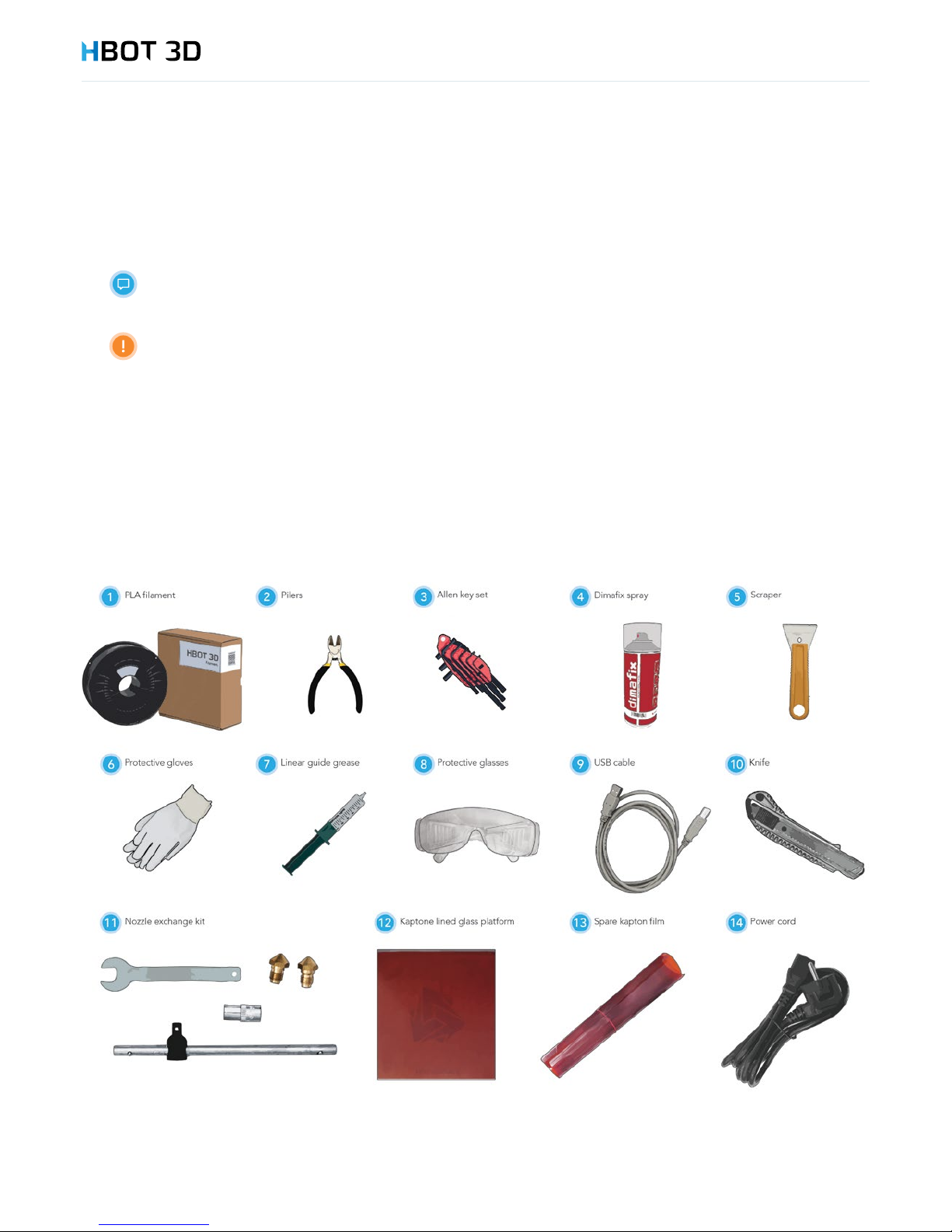
4.1 PACKAGE CONTENT
The Kit contains the HBOT 3D F300 printer (with 0.4 mm nozzle installed and SD Card inserted) and a kit of accessory tools. Also, the
device is accompanied by a Warranty Card and the Short Installation and Commissioning Manual.
First, remove all elements from the top package compartment and check if the following parts are included. If any part of the kit is
missing, contact either the Customer Service Department of 3D Printers, or directly your vendor.
4. Printer Installation
Page 12
6
1
2
3
4
5
4. Printer Installation
12
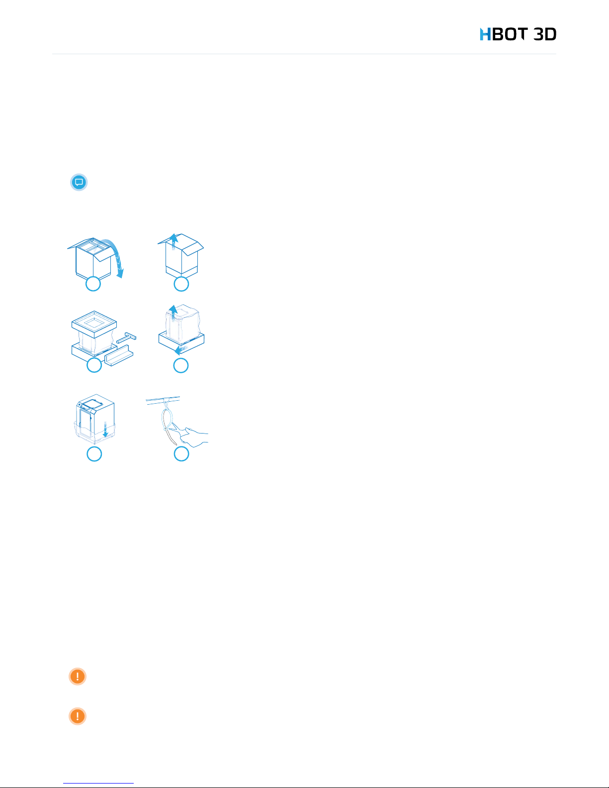
4.2 REMOVING THE TRANSPORT LOCKS
After removing all items and placing them in a safe place, remove other transport locks.
Weight of the device exceeds 30 kg. For safety reasons, it is recommended that these operations
be performed by at least 2 persons.
4.3 SELECTING LOCATION
To ensure operational safety and obtain best printer performance by minimizing vibration or uneven distribution of its weight, the
printer must be erected on a rm surface.
Before installing make sure that the location where the device is to be installed:
• Has a rm and even surface;
• Is located clear of elements that may block the ventilation holes;
• Is clear of direct sunlight;
• Is properly ventilated;
• Is not exposed to negative temperatures (below 0 °C),
• Is located clear of sources of heat and water;
• Provides sufcient footprint to enable full opening of printer doors (front and top);
• Supply outlet and SD Card slot are easily accessible.
The printer may not installed on table top, or structures with inadequate support.
Please note that dangerous toxins may be released from the hot material, so the device must be located in a wellventilated area.
STEP 1
Open the box
STEP 2
Remove the carton by lifting it upwards.
STEP 3
Remove the protective foam pads (one upper and four on each corner).
STEP 4
Lift the device and remove protecting pads under the printer (foam and carton).
STEP 5
Carefully remove the protective bag.
STEP 6
Remove strap protecting clips (inside the printer).
Page 13
900
720
1800
2700
11
MOC
SKUTECZNA [W]
CZAS
[min]
23 48 49
900
720
1800
2700
11
EFFECTIVE POWER
[W]
TIME
[min]
23 48 49
4. Printer Installation
13
4.4 LEVELING
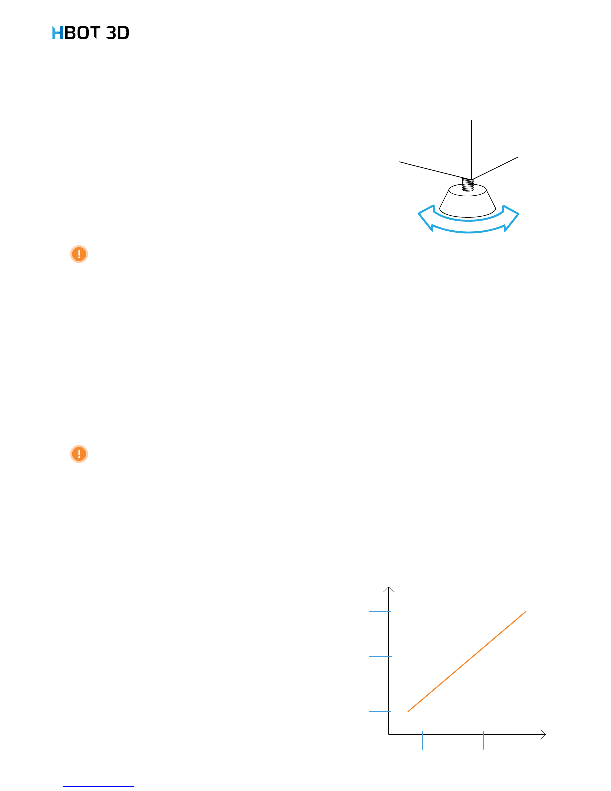
Once the printer is erected on an even and stable surface, it must then be leveled.
There are 4 adjustable feet at the bottom provided specically for this purpose.
Level the device by screwing the feet by hand in the appropriate direction so that
the device is perfectly level both in the x-axis (width) and y-axis (depth).
Check if the printer is resting on all four feet and stable, by pressing at each corner
one after another.
Correct placement and leveling of the device is a must to ensure fault-free operation.
4.5 POWER SUPPLY CONNECTION
STEP 1
Locate the power cord connection on the back panel of the device.
STEP 2
Locate the power switch on the right-side panel and before you power up your printer make sure that the switch is set in the “0”
position (power off).
STEP 3
Unwind the power cord and plug one end to the power cord connection of the printer. Plug the other end of the power cord to
a power outlet provided with an earth pin.
Plugging the device to a power outlet without a fully functional protective earthing is prohibited
STEP 4
Now, when the device is plugged into the power supply mains, set the power switch to the “on” (“1”) position.
STEP 5
Now, the area around the “Stand-by” button should be backlit in soft blue.
4.6 CONNECTION TO EMERGENCY SUPPLY
Your HBOT 3D F300 is suitable to operate in continuous service.
However, in the event of a long-term power outage the printing
operation is interrupted with no option to resume the process.
In environments where long-term power outages occur, the device may
(optionally) be connected to an emergency power supply (UPS) in order
to prevent such situations from happening.
The diagram shows the recommended effective power vs. expected
back-up time.
Page 14
HOT SURFACE
4. Printer Installation
14
4.7 INITIAL COMMISSIONING
This chapter focuses on the initial commissioning process and a test print. Before commissioning the printer be sure to carefully read all
previous chapters of this Manual.
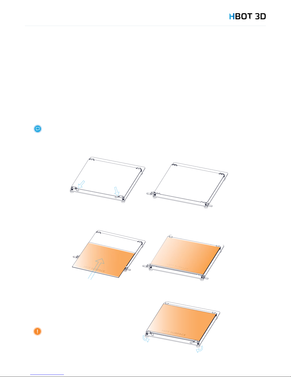
Build platform installation
STEP 1
Unpack the build platform by removing the protective foam pads and make sure that the platform has not been damaged in
transportation.
The build platform included in the kit is a glass platform. It is lined with an exchangeable Kapton lm and
a layer of DIMAFIX adhesive is applied.
STEP 2
Open the hinges holding the glass plate in place.
STEP 3
Slide the glass in the retainer clips, the side with the Kapton lm facing upwards.
STEP 4
Close the hinges holding the glass plate in place.
Make sure that the glass plate
does not project beyond the table
border (either on the left or on the
right).
Page 15
4. Printer Installation
15
Powering up the device
Make sure that the device is plugged to a correctly rated supply and the power switch is set to “1”.
Otherwise go to Chapter 3.5 “Power Supply Connection”.
To power up the device, press and hold the “Stand by” switch for 2 seconds, until the entire rim of
the switch is backlit in blue and the home screen is displayed on the screen.
If the build table was not in its lowest position before power was last turned off, the printer starts
from homeing its position. Before you proceed to next step wait for the device to nish operation.
Printing platform leveling
This procedure must be carried out to ensure correct device operation.
STEP 1
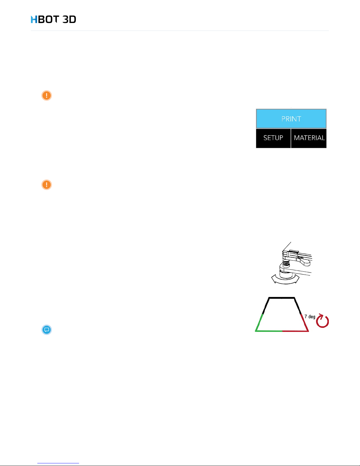
On the control panel select SETUPHOTBED LEVELINGSTART in succession.
STEP 2
The device start calibration from checking the rst corner, and making a series of 3 measurements.
STEP 3
• If the corner is shown in green on the display, it means that the adjustment is not necessary and
the extruder moves to the next corner.
• If the corner is shown in red on the display, it means that you should turn the adjustment nut by
hand in the direction indicated on the display, and then press CHECK. The device repeats the
series of measurements.
In the example shown on the right, turn the front right-hand nut by 7 degrees counterclockwise and
press CHECK.
If any corner require adjustment by more than 45 degrees, the leveling process
must be repeated.
Loading material
STEP 1
The device comes with a 1 kg package of PLA lament. Before proceeding to next steps:
1. Remove the protective foil of the carton;
2. Unpack the lament from the carton;
3. Remove the vacuum packaging foil;
4. Remove desiccant from inside the spool.
STEP 2
On the control panel select MATERIAL INSERT PLAOK in succession.
Page 16
4. Printer Installation
16
STEP 3
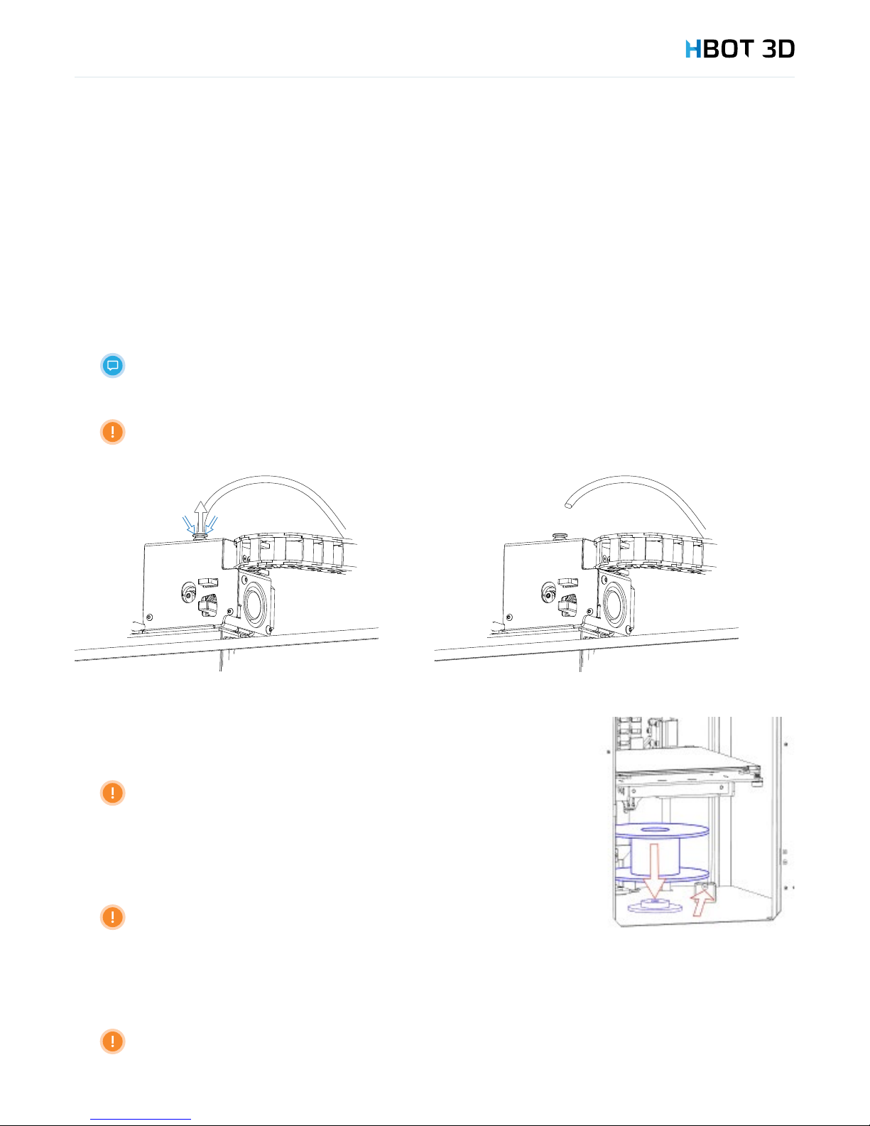
Once the carriage reaches the preset position, the message “Pull out bowden tube from extruder entry” is shown on the screen,
remove the Teon guide tube from extruder entry by pressing the push-t connector collet and conrm by selecting OK.
STEP 2
On the control panel select MATERIAL INSERT PLAOK in succession.
STEP 3
Once the carriage reaches the preset position, the message “Pull out bowden tube from extruder entry” is shown on the screen,
remove the Teon guide tube from extruder entry by pressing the push-t connector collet and conrm by selecting OK.
For easier access to the extruder, open the top door.
The Print Head starts to heat up. Do not touch!
STEP 4
Once the Build Table has reached the preset position, place the lament spool in the holder
located in the bottom of the working chamber, insert its end to the feeder.
Make sure to put the spool with the lament in the right direction, so that
the material is unwound in the counterclockwise direction and the spool can
move freely when feeding the lament.
STEP 5
Continue pushing the lament until its end appears on the other side of the feeder.
Do not allow lament coils to fall off the spool! The material may be
jammed in the feeder entry or material feed into the print head may be
interrupted!
STEP 6
Cut lament end with pliers (included) at an angle of ca. 45 degrees and gently straighten the lament core a bit.
Make sure that the lament end is not bent or torn. Otherwise the material may be jammed
in the print head!
Page 17
4. Printer Installation
17
STEP 7
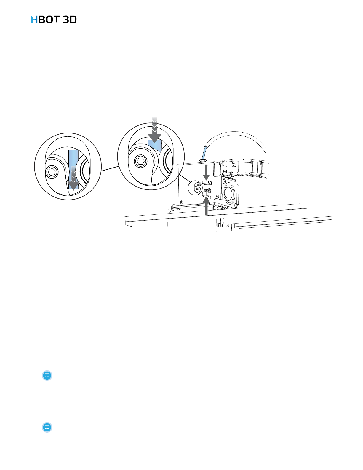
Once the print head has heated up to the correct temperature, the following message appears on the display: “Push new lament
into the extruder entry until it is grabbed by extrusion mechanism.” feed the lament into the extruder until it is grabbed between the
knurled wheel and pressure bearing.
Once you feel resistance, open the pressure lever and push lament into the print head bushing.
STEP 8
Once the message “Is new lament extruded?” appears on the screen, keep selecting NO until a continuous lament thread exits the
print head. Conrm on the screen, by selecting YES.
STEP 9
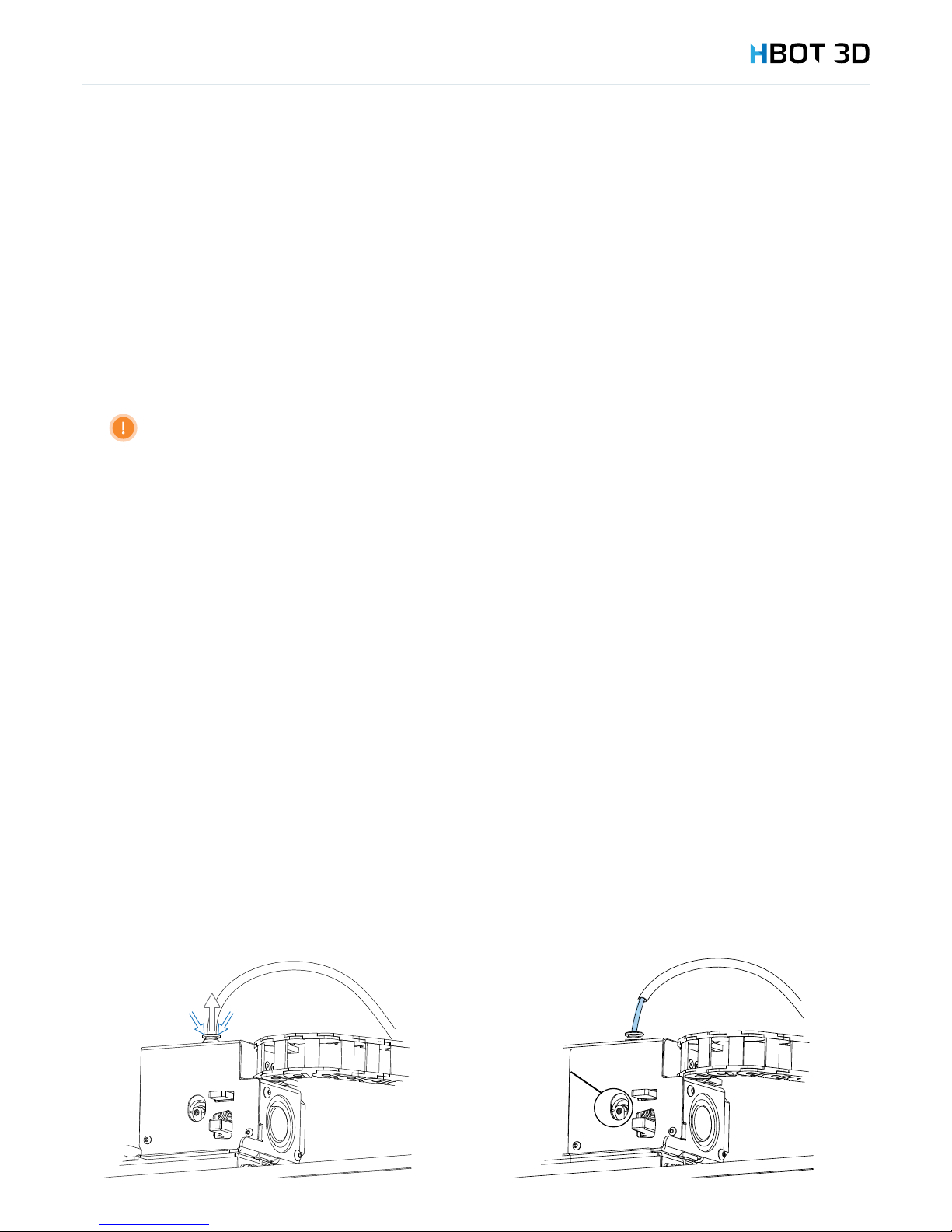
By pressing the blue push-t connector collet, couple guide tube to extruder by sliding it inside.
Starting a print
STEP 1
Select the PRINT command from the control panel
STEP 2
Select the “test_print_PLA” option
STEP 3
The device starts operation from heating up the print head and the build table.
Monitor the start of the printing process.
Once the printing is nished, the message “Finished printing” appears on the screen and the printing time. Select the OK option.
Open the door and remove the build platform. Carefully remove the print using the scraper included in the kit
Be careful not to damage the print and the Kapton lm.
Clean Dimax adhesive and lament residues from the build platform.
Page 18
5. Description of use
18
This chapter describes all steps and workows for correct use of your printer.
5.1 PREPARING THE BUILD PLATFORM
The build platform is supplied with Dimax spray applied thereon. Before printing another print be sure to apply an adhesive layer
onto the platform.
STEP 1
Shake the container
STEP 2
Spread a thin layer of product on the entire surface of the build platform. Make sure that the platform has a room temperature!
Never use the Dimax adhesive inside the device! Remove the build platform from the printer and go to
a well ventilated room, preferably outdoors!
STEP 3
Wait until the layer applied has dried. The surface should be visibly dull
STEP 4
Install the build platform For build platform installation instruction, go to chapter PRINTER INSTALLATION – Initial commissioning –
Build platform installation on page 14.
5.2 STORING MATERIALS
Most materials used in the 3D printing process are sensitive to moisture and UV radiation, so that they should be stored in a dark place,
preferably in an airtight container with a desiccant.
5.3 LOADING MATERIAL
For tips for loading lament refer to chapter PRINTER INSTALLATION – Initial commissioning – Loading material, on page 15.
5.4 REMOVING MATERIAL
STEP 1
Select the REMOVE option from the MATERIAL menu
STEP 2
Once the message “Pull out Bowden tube from extruder entry” appears on the screen – unclamp and pull out the Teon lament
guide from extruder push-t connector and conrm on the screen, by selecting OK.
5. Description of use
Page 19

5. Description of use
19
STEP 3
The print head is heated up to the transition temperature („Preheating nozzle for lament injection”), material is injected and then
backed out from the print head (Removing material).
For easier access to the extruder, open the top door.
The Print Head starts to heat up. Do not touch!
STEP 4
Once the printer has nished the printing process and the message “Pull the lever on the extruder and manually pull out the lament”
appears on the screen, immediately open extruder lever, remove lament and conrm the operation by selecting OK.
Once the message has appeared, remove lament without delay. Do not allow the lament to cool down
inside the extruder.
STEP 5
Using pliers cut the damaged lament tip (ca. 50 mm).
STEP 6
Rewind material back onto the spool, while controlling its end all the time. Once the end exits the lament guide remove the spool
from the device, and insert lament end through a hole in the spool rim.
STEP 7
Conrm the successful removal of material by reselecting OK.
5.5 CHANGING MATERIAL
To switch between different materials you need to combine the material removal procedure (see chapter “Removing material” on page
18) with the material loading procedure (see chapter Initial commissioning - Loading material”, on page 15).
In the event of switching between materials of different types, or between colored and neutral materials it is
helpful to print a small item to completely remove the residues of the previous color in the nozzle.
Page 20

5. Description of use
20
5.6 REPLENISHING MATERIAL
In the event of changing lament color during printing, or if the amount of material on the spool is too small to build the entire model,
it is possible to swap the material during the process.
STEP 1
During printing choose the right moment and click CHANGE. The printer stops once commands cached in the memory are completed.
STEP 2
Once the print head has stopped go to menu OPERATOR PANEL as soon as possible, and select DOWN several times until the Build
Table travels down by ca. 50 mm.
STEP 3
Using the four FRONT, BACK, LEFT, RIGHT buttons position the carriage in a place convenient to change materials.
STEP 4
Follow the changing material procedure. Decouple the extruder push-t connector and remove the Teon lament guide tube, then
press extruder lever and remove material from the print head. (Refer to chapter “Changing material” on page 23).
Extruder may be hot! Be sure to wear protective gloves!
STEP 5
While holding the pressure lever and with decoupled lament guide tube, grasp lament a few centimeters above the extruder and
push it in through the print head until a continuous thread exits the nozzle.
STEP 6
Remove the pressed lament thread and couple lament guide tube to extruder push-t connector.
STEP 7
On the display, select BACK , then UNPAUSE. The printer will resume printing from where it has stopped.
5.7 STARTING A PRINT
We assume that:
1. relevant .gcode le has been saved on the SD card;
2. printing platform is clean and Dimax spray has been applied;
3. correct material has been loaded;
4. the device has correct nozzle installed in it.
To start a print, select the relevant print le from the list in menu PRINT, then conrm your selection by pressing OK. Now, the carriage
is reset to the home position and the build table starts resetting to zero.
Every time you touch the extruder or carriage when homeing the build table may result in its early stoppage
and error in starting print!
Before selecting the print le make sure that no lament residue remains on the nozzle. It the nozzle is
crusted you must clean it.
Once resetting the printer is nished, the device is warmed up to an appropriate printing temperature and thermally stabilized. It can
take several minutes. Then, the printing process starts automatically.
Page 21

5. Description of use
21
5.8 PAUSING AND RESUMING PRINT
To pause the print with the option for resuming, on the “PRINT” screen, choose
the CHANGE option. Once the cached commands are completed, the printer will stop. Now, you have the option to move the carriage
(select OPERATOR PANEL and then travel the build table by selecting DOWN and use the FRONT, BACK, LEFT, RIGHT buttons), or
change/replenish the material (see page 26).
To resume printing, exit the OPERATOR PANEL screen by pressing the BACK button, then select UNPAUSE. Now, the printer travels
back to the position where the print was interrupted and resumes printing.
Before resuming printing, remove the lament thread which escaped from the print head under gravity.
The print may not be paused before the warming procedure is nished.
5.9 ABORTING PRINT
To interrupt print without the option for resuming, on the “PRINT” screen, choose
the ABORT option and conrm print cancellation by means of the OK button. Now, the printer completes printing and the carriage
travels to the home position and the build table travels to the bottom of the working chamber.
5.10 FINISHING PRINT
Once the print is nished, the “Finished printing” massage is displayed together with the total printing time. Device carriage travels to
the home position and the build table travels to the bottom of the working chamber.
5.11 REMOVING PRINT FROM THE BUILD PLATFORM
STEP 1
Make sure that the temperature of the build platform is below 30°C. You can check the current print head temperature by selecting
SETUP from main menu and then INFORMATIONS.
STEP 2
Slide the platform from the device and place it on a at surface.
STEP 3
Use a knife or scraper (included) to gently pry the print and unstick it from the printing platform.
Scraper corners are very sharp! Be careful not to damage the Kapton lm when unsticking the print!
STEP 4
Carefully remove lament residues from the printing platform (skirt and brims around the model) and rell the footprint of the removed
model with DIMAFIX adhesive.
Only handle DIMAFIX in well-ventilated areas, never inside the printer!
Page 22
5. Description of use
22
5.12 REMOVING SUPPORT STRUCTURES
For sophisticated geometry models the printer also prints support structures, i.e. parts of the print which are not parts of your model
and should be removed mechanically. In most cases simple tools such as pliers, at screwdriver, or tweezers will do.
For safety reasons, it is recommended to wear protective gloves and glasses included in the kit.
5.13 NOZZLE REPLACEMENT
STEP 1
Prepare the necessary items included in the kit:
1. Protective gloves
2. Nozzle Kit (Special 10 mm at wrench, 8 mm socket adapter, ratchet or adapter handle)
3. 2 mm Allen key
4. Replacement nozzle
STEP 2
If lament have already been loaded, remove it (refer to chapter Removing lament on page 18).
STEP 3
In the SETUP menu select the NOZZLE EXCHANGE option and conrm by selecting OK. The carriage will travel to the middle
position and the print head will start warming up to the nozzle exchange temperature.
The print head is hot! Be sure to wear protective gloves!
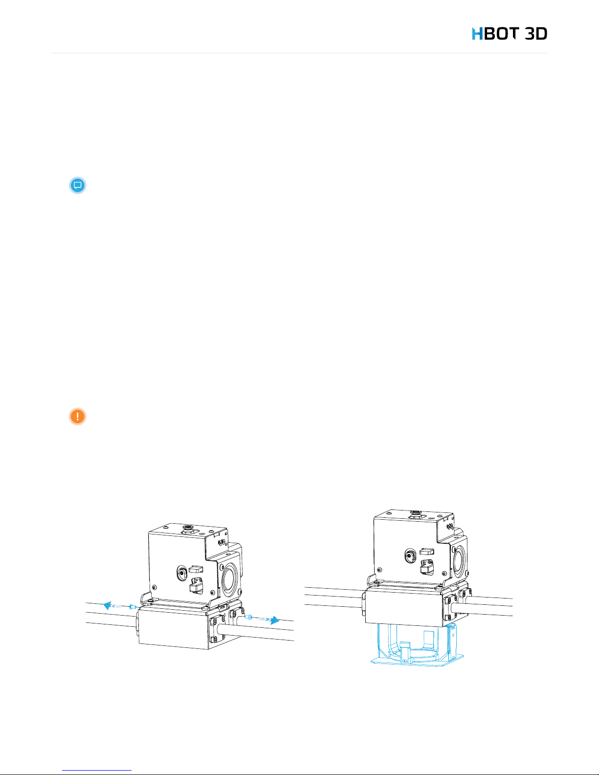
STEP 3
Once the message “Change nozzle now” appears on the screen, use the 2 mm Allen key to remove two M3 screws located between
bearings on both sides of the carriage and remove the carriage cover with cooling channels.
Page 23
5. Description of use
23
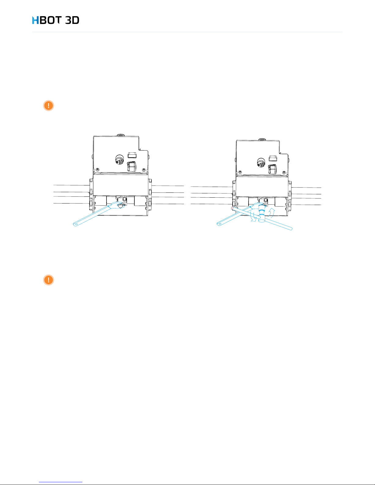
STEP 5
Using the 10 mm wrench to hold the block, screw the replacement nozzle into the heater block, then tighten the nozzle using the 8 mm
socket adapter until you feel resistance.
Adapt the nozzle tightening torque to eliminate the clearance between nozzle and the heater block.
STEP 6
Reinstall the carriage cover with cooling channels
STEP 7
Replace two M3 screws.
STEP 4
Using the 10 mm at wrench hold the print head block, then using handle with the 8 mm socket adapter remove the nozzle.
Firmly hold the heater block using the 10 mm wrench! Do not allow the block and head to rotate around its axis!
Page 24
6. Preparing les
24
Your HBOT 3D F300 builds a real model on the basis of instructions saved on an SD Card in the format of a .gcode le. Every printing
process needs an individual .gcode le, which stores all printing data and model coordinates. A .gcode le is generated using the
Simplify 3D Software included in the kit. This chapter describes the software program installation process, its essential features, and
steps to be followed to correctly prepare les for your printing job.
For additional information we encourage you to refer to the knowledge base on the manufacturer’s website at: www.simplify3d.com
6.1 INSTALLATION OF SIMPLIFY 3D
STEP 1
Log in to your account at: www.simplify3d.com in the Account tab using the credentials provided by Simplify3D Support Team to the
e-mail address specied when purchasing the device.
If you did not receive an e-mail with login credentials, contact our Technical Department by email at: [email protected]
STEP 2
Change the default access password
STEP 3
Download the software installation le by selecting a version appropriate for your operating system from the Download Software tab.
STEP 4
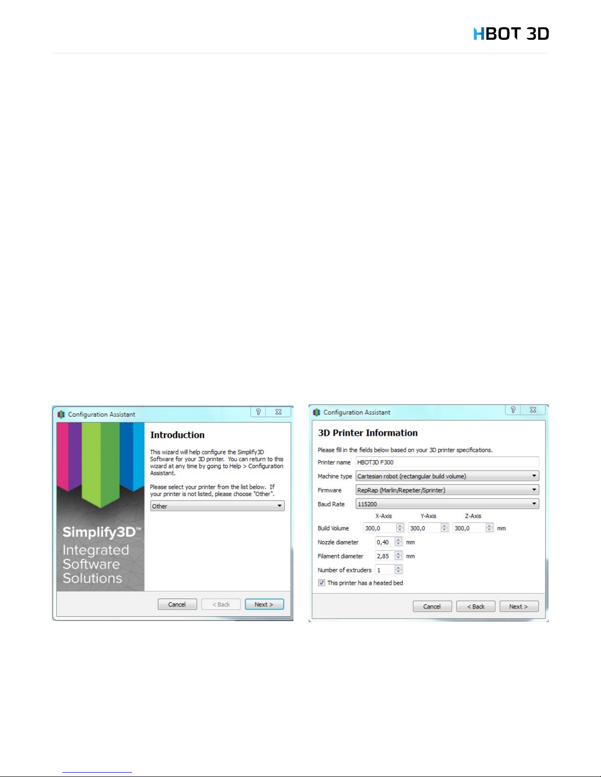
Follow the instructions in the wizard. Once you go through standard settings and the “Introduction” screen appears, select Other from
the drop-down list and ll in the elds as shown in the following diagram.
6. Preparing les
Page 25
6. Preparing les
25
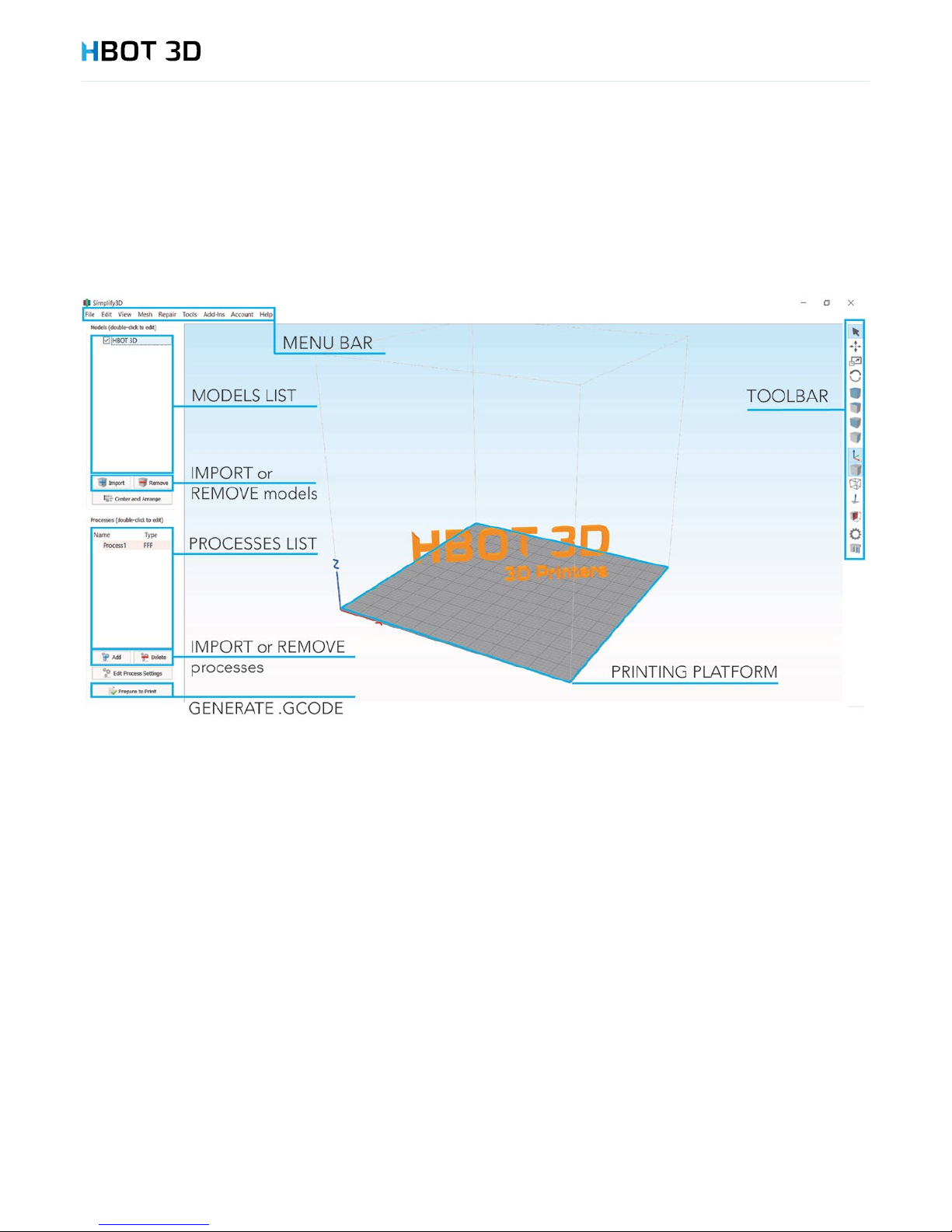
6.2 GRAPHICAL USER INTERFACE
You should familiarize yourself with elements of graphical user interface of Simplify 3D. Names used on the following illustration are
often referred to later in this manual and without knowing them you will not be able to properly prepare your le for printing.
6.3 IMPORTING MATERIAL CONFIGURATIONS
To correctly generate a print le you have to import the material congurations prepared by us. Correct completion of this operation
enables you to correctly congure basic parameters of your machine.
STEP 1
Download the latest package of material congurations from manufacturer’s website at www.hbot3d.com and save in the selected
location on your computer disk.
STEP 2
Unpack all les. Make sure that ve les with the *.fff extension have been unzipped to the Congurations folder.
STEP 3
From the menu bar select FileImport FFF Prole, locate the folder with the saved les, select all and choose OK.
After a while a message appears conrming that the conguration has been imported into the program memory.
Page 26
6. Preparing les
26
6.4 MODIFYING THE DEFAULT SETTINGS
In order to improve the comfort of working with Simplify 3D it is recommended to modify some settings.
From the menu bar select ToolsOptions and modify your settings in accordance with the following guidelines:
Tab Parameter Setting
Preferences
Speed Display Units mm/s
Middle mouse button resets view deselected
Always show full 3D transform gizmo selected
Visualization Use orthographic camera with no perspective selected
6.5 IMPORTING MODELS AND ORIENTATION
Importing
Importselect one or several les to be imported into your project.
Supported le formats: *.STL i *.OBJ.
Automatic orientation
Center and Arrange
To bring your model dropped below the build platform to the build table, select EditDrop Model to Table.
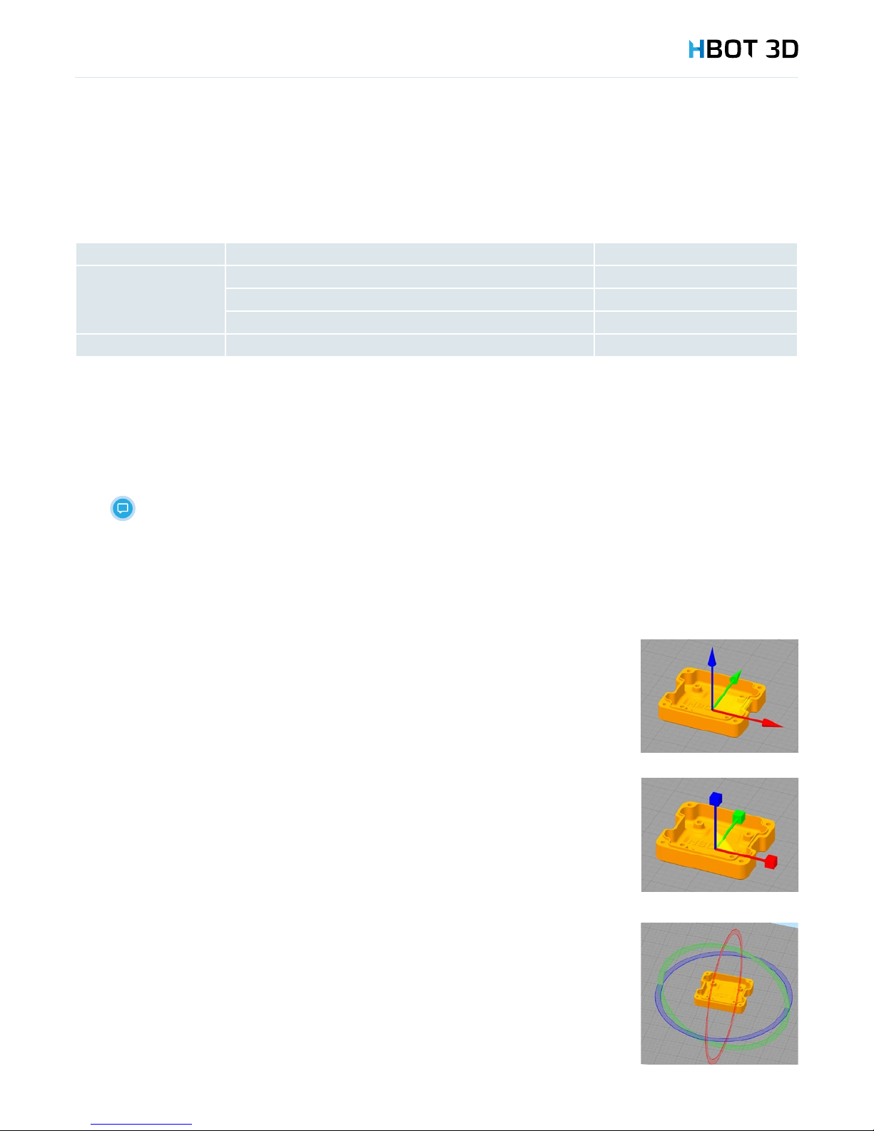
Moving
From the menu bar select Translate models
Catch your model and move it freely in the XY plane. By selecting appropriate arrows move your model
towards a given axis.
Scaling
From the menu bar select Scale models
If you want your model to be to scaled up or down while maintaining a uniform scaling, click
on the model and drag in any direction. If you want to stretch or shrink your model along just one
axis, catch and drag the cube of the relevant axis.
Rotating
From the menu bar select Rotate models
To rotate your model around a given axis, click on the respective ring and drag.
Page 27
6. Preparing les
27
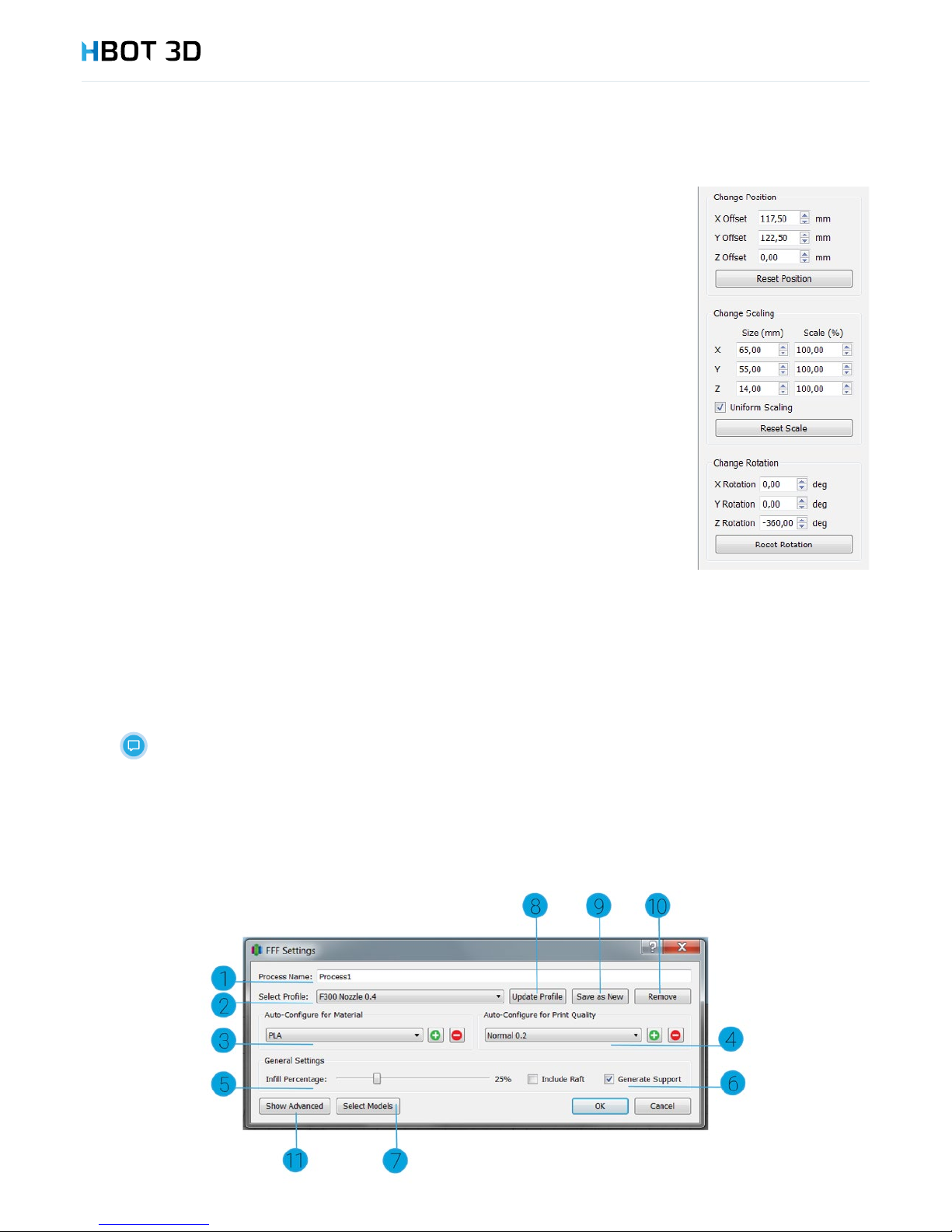
Free transformation
To set the exact position, scale and rotation of your model, double-click on the model. It will pop up
a menu bar on the right. In the rst eld you can change the name of your model in the project.
Change Position allows you to enter the exact position of the center of the model coordinate system in
relation to the center of the build platform coordinate system.
Change Scaling allows you to change your model dimensions by entering new dimension or a scale
value. Also, it is possible to disable the scaling factor (Uniform scaling)
Change Rotation rotates your model by a precise value in degrees.
Each section has a reset button for resetting position, scale and rotation to your default settings.
Orientation relative to the surface
From the menu bar select EditPlace Surface on Bed
Click on the selected triangle of your model.
Copying
From the menu bar select EditDuplicate Models
In the window enter the number of copies and conrm by clicking Copy
Mirroring
From the menu bar select EditMirror Mesh
Select the axis in which you want your model to be mirrored.
Visibility
To hide or unhide your model on the project printing platform, either select or deselect the checkbox next to the name of the model in
the list of downloaded models.
Deselecting a checkbox and hiding the model will not delete the le from your project.
6.6 CONFIGURING PRINTING PARAMETERS
Page 28
6. Preparing les
28
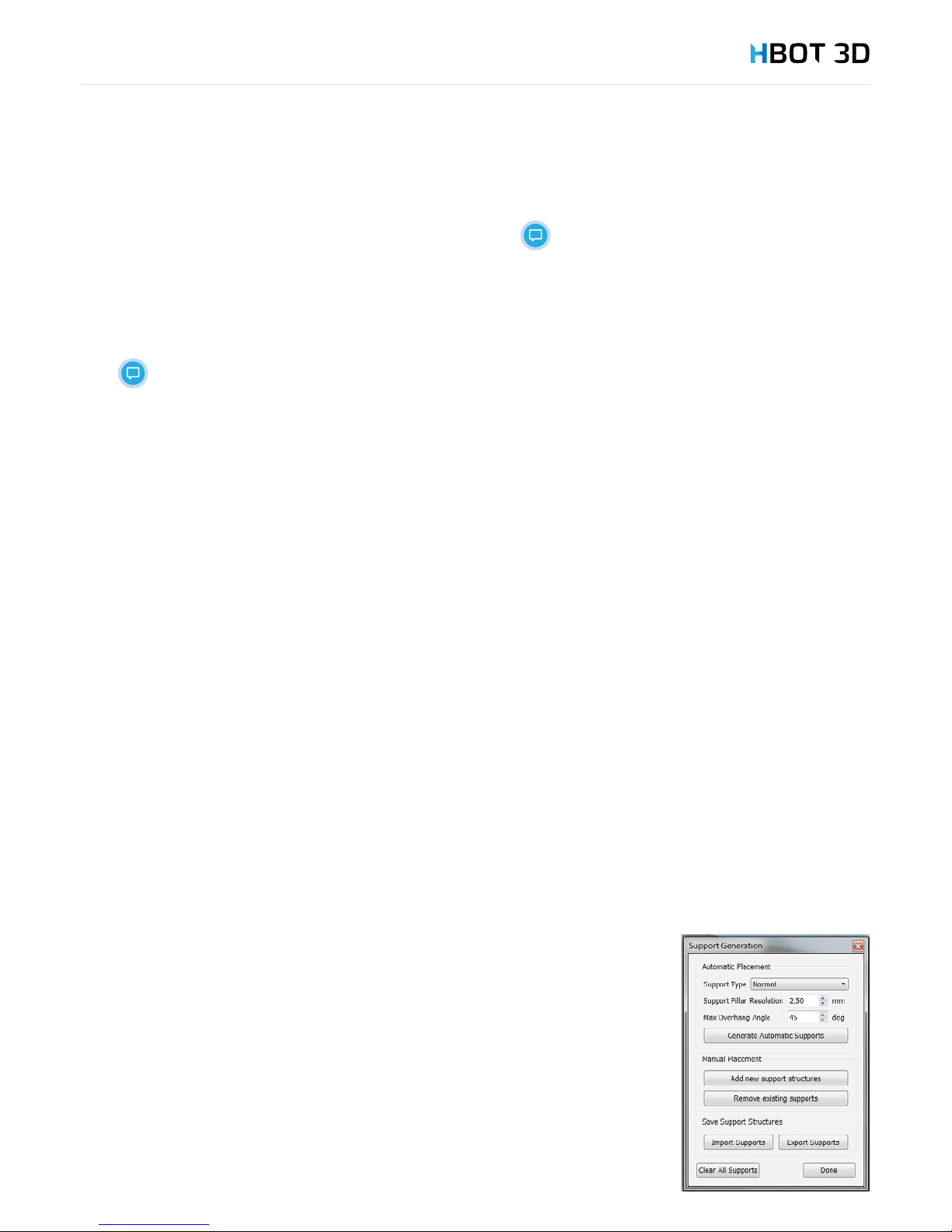
1. Naming the process
2. Selecting conguration (one of ve previously imported,
depending on the diameter of the currently installed nozzle).
3. Selecting lament
4. Setting layer height (print quality) . Different layer heights are
available depending on nozzle diameter
5. Model interior ll percentage The higher the interior ll
percentage, the more resistant model, but higher material
consumption and longer print time.
If the interior ll percentage is too low, pillowing
can occur on the upper surfaces of your model!
Using the interior ll percentage lower than 15% is
not recommended.
6. Generating support structures.
This option may only be deselected in special
cases! We recommend that the Generate Support
option should be enabled (selected)
7. Selecting models affected by the process
8. Saving changes to the conguration
9. Adding new conguration
10. Removing conguration
11. Advanced process parameters
6.7 DISPLAYING PRINT PREVIEW AND EXPORTING CONTROL COMMANDS
Once the model is correctly oriented on the build platform and basic process parameters have been congured, you can proceed to
generating control commands.
Use the Prepare to Print button. The program will start generating control commands for your 3D printer. It may take between a few
seconds to several minutes, depending on the complexity of your model, the accuracy of the triangle inll pattern of the STL le and
the computing power of the computer. Once the travel paths are generated the program will proceed to print preview.
Section 1 contains information regarding the estimated print time, length and weight of material necessary to print your model and
the cost of consumed material.
In section 2 you decide which elements of the print preview are shown:
• Build table – a preview of the build platform
• Toolhead – a preview of the print head
• Travel moves – showing idle movements of the print head
• Retractions – showing retraction points
• Coloring – options for colors used to represent different features of your model (movement speed – depending on the print head
linear speed, active toolhead – depending on the currently selected print head, feature type – depending on the type of model
feature that is printed)
Slider (5) allows you to keep track of the building of your model, line-by-line or layer-by-layer.
In section 2 you change default settings for displaying print preview:
1. deselect the Travel moves option
2. from Coloring drop-down list select Feature Type. This allows you a much more clear preview of the printed model.
Button Save Toolpaths to Disc (3) exports the control instructions to a .gcode le, which is then saved on the SD card of your printer.
To return to the parameter edit mode use the Exit Preview Mode pushbutton (4)
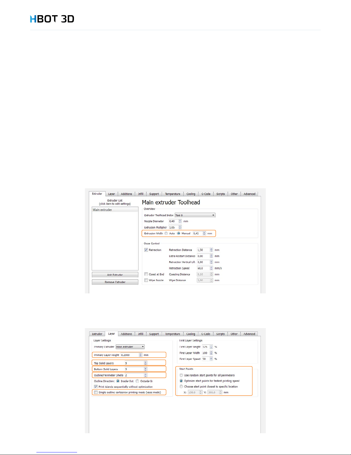
6.8 EDITING SUPPORT STRUCTURES
Depending on the requirements of your model, it is possible to manually edit support structures.
From menu bar select ToolsCustomize Support Structures.
Support Type
In the rst eld select the type of generated support structures. The rst option generates supports
everywhere, where model’s overhang angle is greater than the allowable one (Max Overhang
Angle). The second option From Build Platform Only will only generate supports between the
printing platform and the model.
Resolution
In the Support Pillar Resolution eld you set the resolution of generating the preview of support
structures. This parameter determines how the model exactly will be supported, but without setting
the inll density of support structures.
To generate supports use the Generate Automatic Supports button.
Page 29
6. Preparing les
29
Editing supports
1. To add a new support use the Add new support structures button, then place the pillar in the desired place of your model.
2. To delete a support use the Remove existing supports button, then click the support you want to delete.
3. To reset all supports and restore automatic support placement, use the Clear All Supports button.
6.9 ADVANCED PRINT PARAMETERS
Simplify3D Software allows you to change more than ve basic print parameters. To edit advanced parameters, open the FFF Settings
window to edit process parameters (the Edit Process Settings button or double-click on the process name) and then select Show
Advanced.
We recommend you to ONLY edit the parameters described in this Manual. Incorrect conguration of the
other parameters may result in a failed print or even a damage to your printer.
Extruder tab
Extrusion Width – width of the paths laid down during extrusion. This value may be set between 100% up to 120% of nozzle diameter.
Layer tab
The Layer tab contains all layer related parameters. Primary layer height is the basic layer height. You can change this parameter if you
need to use other layer height than the one dened in the drop-down list in section Auto-Congure for Print Quality. The minimum
layer height is 0.25 and the maximum one - 0.75 of nozzle diameter.
Page 30
6. Preparing les
30
With the change of the layer height, two other parameters must be modied: Top Solid Layers and Bottom Solid Layers – i.e. the
number of top and bottom layers. Their number multiplied by the layer height should be at least 0.8 mm. By increasing the number of
layers you increase respectively the thickness of the top or bottom wall of the model.
Side wall thickness is governed by the Outline/Perimeter Shells parameter, i.e. the number of outlines forming your model wall. The
more outlines, the thicker the wall and therefore the mode rigid and stronger the model.
Single outline corkscrew printing mode (vase mode) – the so-called vase mode. In this mode the printer will not print an inll but
the print head moves simultaneously with the build table and prints a continuous “spiral” track. This mode is appropriate for printing
models with a single outline (e.g. a bottle, vase). In this mode no supports are produced, so the maximum overhang angle of the
model is 45 degrees.
Start points
This section enables you to select start and end points for creating outlines.
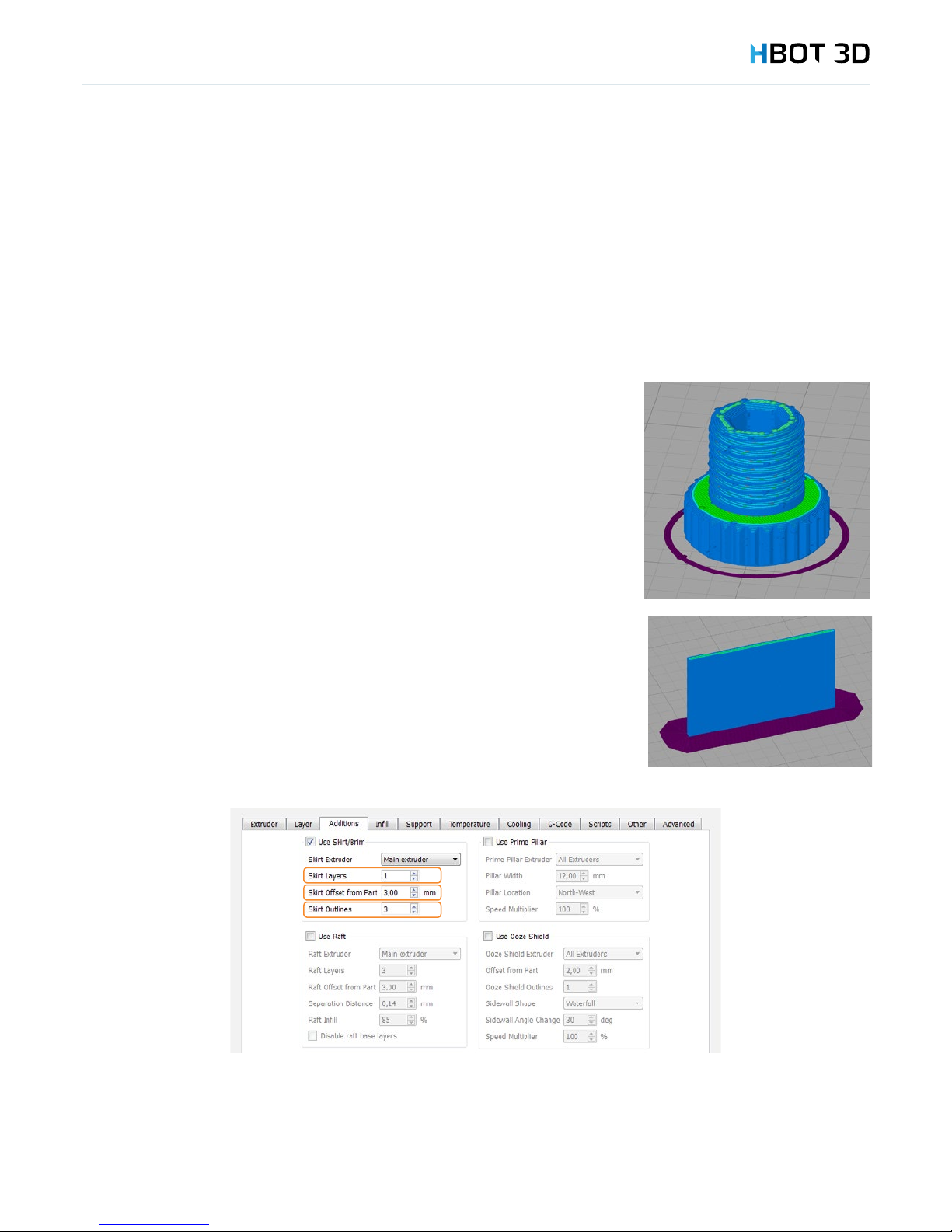
The rst option “Use random start points for all perimeters” randomizes the points around
model wall and makes them less visible (picture on the right).
The second option “Optimize start points for fastest printing speed” allows the software to
optimize the layout of starting points so as to increase the speed the printing process.
The third option “Choose start points closest to specic location” allows you to line-up your
starting points in a selected coordinate on the printing platform.
Additions tab
In this tab you can dene parameters of the initial outline.
Default outline, the so-called Skirt is an outline that does not touch the print and is generated
to stabilize the ow of material from the nozzle. For high prints with a small surface area
touching the printing platform, it is useful to create a wider rst layer (Brim) to help with
adhesion of the model to the printing platform.
To create a Brim around your model, set the Skirt Offset from Part parameter to 0 and the
Skirt Outlines to min. 10 (the more skirt outlines, the wider layer is attached to your model).
Also, for tall models and very small surface area of contact with the build platform you can
increase the number of Brim layers - Skirt Layers.
Page 31
6. Preparing les
31
Inll tab
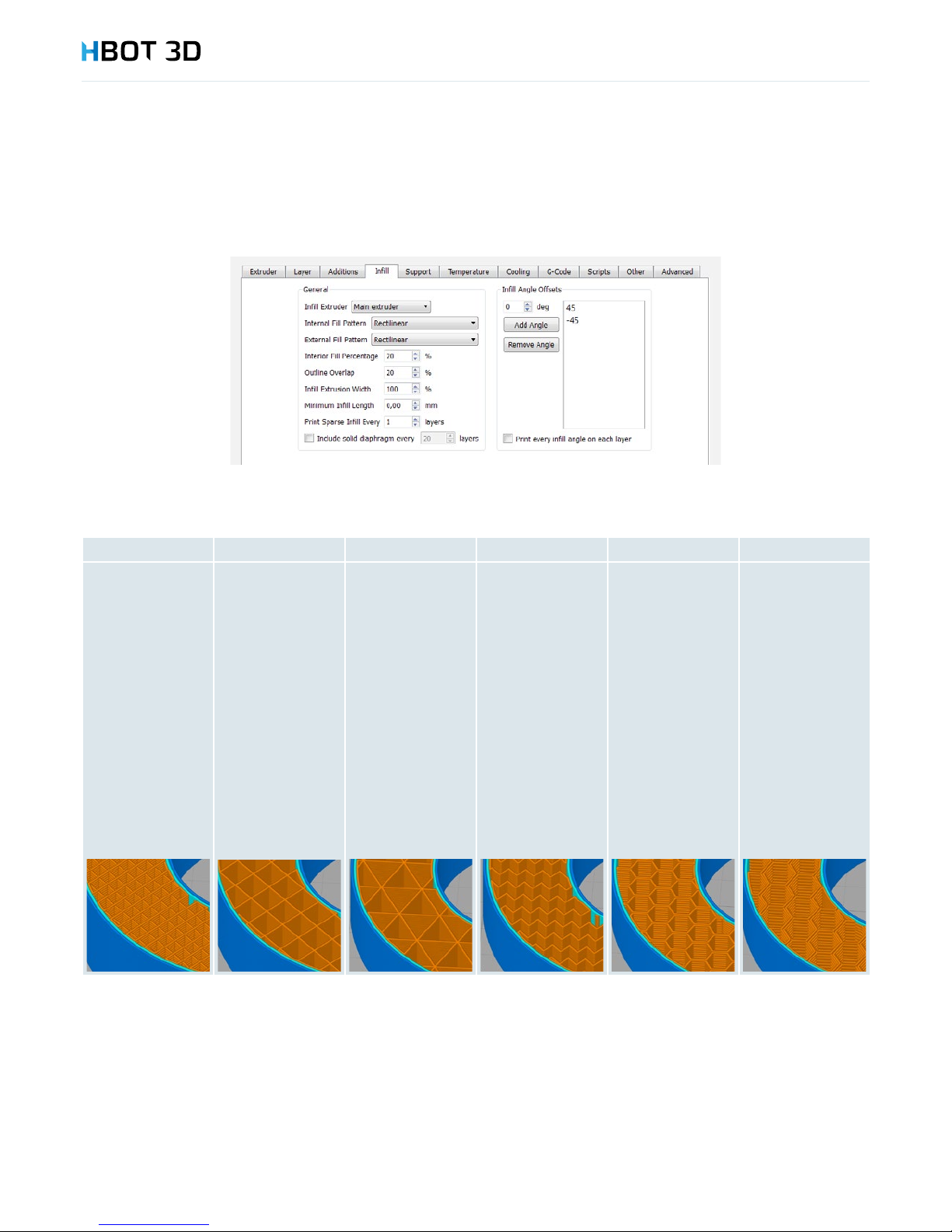
This sections enables you to modify interior ll parameters, mainly inll density and inll pattern (Interior Fill Percentage and Internal Fill
Pattern).
You have 6 different inll patterns to choose from:
Rectilinear Grid Triangular Wiggle Fast Honeycomb Full Honeycomb
Inll pattern
with the lowest
strength for low
inll percentage,
highest strength
for 80-100% inll
percentage. It is the
only inll pattern
that could be set to
100%. Inll paths do
not intersect within
the same layer.
Inll pattern with
a higher strength
for lower inll
percentages.
Maximum setting
which if congured
will not cause print
problems is 80%,
but the optimum
one is 20-40%. This
shape differs from
the Rectilinear
one in that the
paths intersect one
another within the
same layer, causing
better adhesion of
the entire inll.
The same inll
pattern as Grid, but
inll paths intersect
with one another
at 60-degrees. This
is the most stiff
and strongest inll
pattern for low inll
percentages. Like
in the case of the
Grid inll pattern,
maximum inll
percentage is 80%
and the optimum
one is 20-40%.
Polyline-shaped
inll pattern.
Simplied
honeycomb. A
structure with
similar properties
to the Triangular
one, also stiff but
less strong than the
full honeycomb.
Maximum inll
percentage is 80%,
and the optimum
one is 20-40%.
Full honeycomb.
Characteristic for
double inll path,
making the structure
very strong at low
inll percentages.
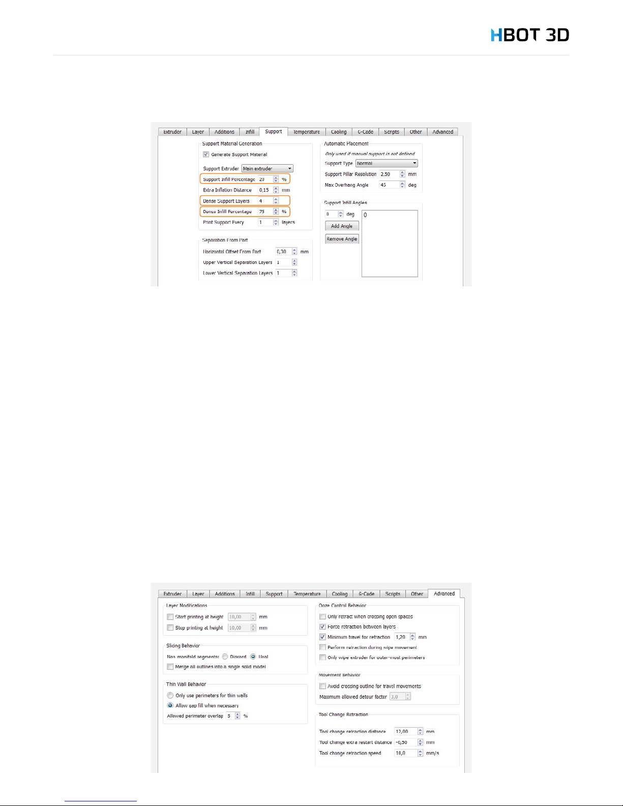
Support tab
Support Inll Percentage – inll density of support structures. The higher the inll density, the more accurately the support structures
are lled, but the print time and material consumption signicantly increase. Optimum value of this parameter is 20%.
Dense Support Layers – the number of support layers with the dense inll percentage where paths of your model are directly laid
down at. The more number of solid layers, the better support for curved and rounded surface. If support structures need to be quickly
removed, you may set the number of dense support layers to 0, but the quality of supported surface will be much worse.
Dense Inll Percentage – inll percentage of the dense support layers. The less density, the easier support removal but the lower
quality of the supported model surface.
Page 32
6. Preparing les
32
Temperature tab
Parameters in this tab are critical for the print process to run correctly.
Without rst contacting our Technical Department it is not recommended that you modify any parameter in this tab.
Cooling tab
Parameters in this tab are critical for the print process to run correctly.
Without rst contacting our Technical Department it is not recommended that you modify any parameter in this tab.
G-code tab
Parameters in this tab are critical for the print process to run correctly.
Without rst contacting our Technical Department it is not recommended that you modify any parameter in this tab.
Scripts tab
Parameters in this tab are critical for the print process to run correctly.
Without rst contacting our Technical Department it is not recommended that you modify any parameter in this tab.
Other tab
Parameters in this tab are critical for the print process to run correctly.
Without rst contacting our Technical Department it is not recommended that you modify any parameter in this tab.
Advanced tab
Using the Start printing at height and Stop printing at height options it is possible to start or stop a print at a specic model height.
It allows you to combine several processes in the same model and dene different settings for your print, e.g. different layer heights
or inll percentages. You need to remember that a next process must begin at the same height where the previous one has been
completed. Otherwise the print may fail.
Page 33
6. Preparing les
33
6.10 SAVING A PROJECT
Simplify3D Software enables you to save the entire project to a *.factory le. It allows you to save the arrangement of your models on
the printing platform and all settings to an external le.
To save a new project choose FileSave Factory File As…
To save changes to a previously created project choose FileSave Factory File.
6.11 ADDITIONAL SOFTWARE OPTIONS
Preview of a generated gcode le
To open a graphical preview of a previously generated .gcode le, select FilePreview G-Code File… from the menu bar.
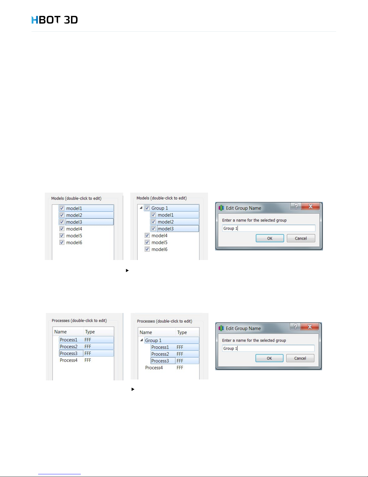
Grouping loaded models
For easier manipulation of the loaded models it is possible to create a group of models. Creating a group of models allows you to
move, scale, rotate and copy multiple models at a time.
To add models to a group, press and hold the SHIFT key and click model names that you want to group. Then, from the menu bar
select EditGroup Selection. Double-clicking lets you edit the name of the new group.
To ungroup multiple models select Edit
Ungroup Selection
Grouping processes
Similarly to creating groups of models, it is possible to create groups of processes. To add multiple process to a new group, press and
hold the SHIFT key, select the processes and then select EditGroup Selection. To change a name of the created group, double
click its name and enter a new group name in the pop-up window.
To ungroup multiple processes select Edit
Ungroup Selection
Separating an STL le into individual parts
When generating an .STL le based on a model composed of multiple elements in an external CAD software it may happen that
Simplify3D Software generates an incorrect .gcode le when combining these elements. If this is the case, it is necessary to rst separate
the components of the combined .STL le and then allow the software to combine these elements when generating control commands.
To separate components of an .STL le select the MeshSeparate Connected Surfaces option from the menu bar. Depending on
model size and its complexity it can take up to several minutes. Following separation, all components of the .STL le will appear as new
models on the list of loaded models.
Page 34

6. Preparing les
34
6.12 USING SD CARD AND USB PORT
To launch the created .gcode le on the printer, save it to your device memory card. There are two options for transferring the le on
the printer SD card:
1. Remove the SD card from the device and put it in a SD card reader of your computer and then copy the le directly to the card.
2.
3. Connect your computer by USB cable to the printer and copy the le to the SD card without removing it from the device.
Device USB port is located on its left panel (see the “Device Description” chapter), USB cable is included. Once the device is
connected to the computer, it should be detected by the computer as a mass storage device.
Page 35

7. Maintenance and operation
35
Routine inspection and maintenance of the device will guarantee the highest quality prints and helps you to increase the reliability of
your printer. Your failure to perform these operations will speed up the wear of your printer and increased risk of failures.
7.1 RECOMMENDED MAINTENANCE OPERATIONS
Repairs or maintenance must be made after power has been cut off to your printer.
Operation Frequency Instructions
Printer cleaning Before each print Remove unnecessary items and excessive dust from printer
interior and clear air fans
Cleaning the build platform Before each print Wash the platform under running water and wipe it dry
Applying Dimax adhesive Before each print Before putting the printing platform back into the printer, apply
a thin layer of Dimax spray on its upper surface (outdoors or in a
ventilated room)
Exchanging Kapton lm If damaged Should either a torn portion of Kapton lm, or noticeable
scratches be present that would affect print quality, carefully
remove the worn Kapton lm. Wash and dry the glass platform
thoroughly. Unstick, pull off, and hold the rst 30 mm piece of
adhesive securing lm from a new Kapton sheet (shorter edge
of the lm). Lay the beginning of the Kapton lm, the adhesive
side down, onto the shorter edge of glass platform so that it
overhangs ca. 5 mm beyond the platform edge, then carefully
stick the lm on platform edge. Hold down the stuck portion of
the Kapton lm with a squeegee and pressing the lm against the
glass, slowly move the squeegee along the lm so that the entire
Kapton lm is stuck to the platform. The securing lm should
unstick itself as you move the squeegee. To increase slippage of
the squeegee, spray the Kapton lm with a small amount of glass
cleaner. Trim the excess of the Kapton lm on longer sides of the
glass platform, ush with platform edge. Using a ruler, trim the
lm on shorter sides of the platform, 5 mm from platform edge, to
expose the glass surface.
Nozzle replacement If damaged Print nozzle replacement must be made if the nozzle gets
overheated or deformed. (Refer to chapter "Nozzle replacement"
on page 19).
Print head replacement Every 12 months* or 4 000 h Contact the Service Department of the manufacturer
Lubricating guides Every 1 month* or 300 h Position the carriage in its middle position (SetupOperator
panel). Wipe away the old grease from the guides (with a paper
towel or clean cloth). Apply an amount of pea sized grease
amount to each guide at each bearing (4 carriage bearings, 2
bearings on the right Y-guide and 2 bearings on the left Y-guide).
Using the front, back, left and right buttons travel the carriage
along the entire operating range to spread the grease along the
guides
Belt tensioning Every 6 months* or 2 000 h Loosen 4 xing screws of the left stepper motor. Push the motor
back and tighten back the screws while holding the motor.
Printing platform leveling Once a week* or every 75 h See the "Printing platform leveling" chapter on page 13
Cleaning the knurled wheel Once a week* or every 75 h Clean the knurled wheel by blowing out with compressed air
through the hole in the extruder case so as to remove any leftover
lament chips.
Firmware update 1 month Once a month check on the manufacturer's website if an updated
software version, or new material congurations are available
* assuming that the average device operating time is 15 h/ day, 5 days/ week.
7. Maintenance and operation
Page 36

Contact us!
+48 71 727 62 04
WWW.HBOT3D.COM
TECHNICAL SUPPORT
Before contacting our Service Department try to troubleshoot
the problem by yourself (e.g. by restarting the device).
Please prepare the serial number of your printer (S/N) located on the
nameplate on the back panel of the printer or in the Warranty Card
accompanying the device.
 Loading...