

Page 1
Operating Manual | Bedienungsanleitung
English Deutsch
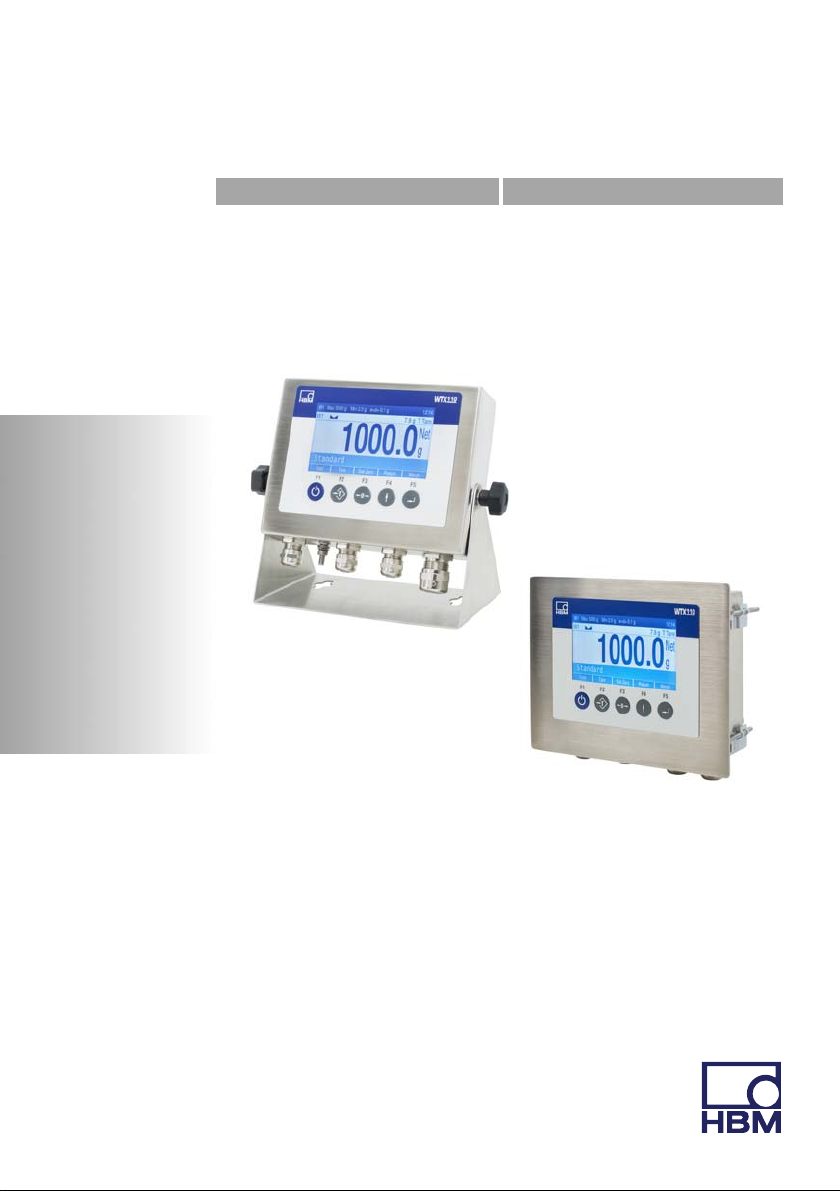
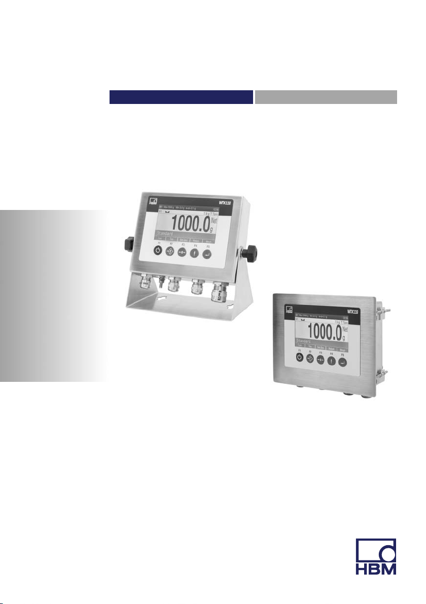
WTX110
Page 2

Hottinger Baldwin Messtechnik GmbH
Im Tiefen See 45
D-64239 Darmstadt
Tel. +49 6151 803-0
Fax +49 6151 803-9100
info@hbm.com
www.hbm.com
Mat.:
DVS: A4774-1.0 HBM: public
12.2017
Program version: ≥ Firmware Update_20160412.1.IT468E
E Hottinger Baldwin Messtechnik GmbH.
Subject to modifications.
All product descriptions are for general information only.
They are not to be understood as a guarantee of quality or
durability.
Änderungen vorbehalten.
Alle Angaben beschreiben unsere Produkte in allgemeiner
Form. Sie stellen keine Beschaffenheits- oder Haltbarkeits
garantie dar.
Page 3
Operating Manual | Bedienungsanleitung
English Deutsch
WTX110
Page 4

English
1 Safety instructions 9.......................................
2 Markings used 14...........................................
2.1 The markings used in this document 14.........................
2.2 Markings used on the device 15...............................
3 System description 17......................................
4 Installation 20..............................................
4.1 Overview of connections 20...................................
4.1.1 ADM (analog sensors) 20.....................................
4.1.2 Serial interfaces 21..........................................
4.1.3 Digital inputs/outputs 22......................................
4.1.4 Analog output 24............................................
4.2 Setup and installation 24......................................
4.3 Mains connection 25.........................................
4.4 General cable assembly 26...................................
4.5 Connection of analog SG sensors 27...........................
4.5.1 Connection cable for analog load cell 29........................
4.5.2 Saving calibration data for legal for trade applications 30..........
4.6 Serial interface connection 32.................................
4.7 USB connection 35..........................................
4.8 Ethernet TCP/IP connection 35................................
4.9 Digital inputs/outputs 36......................................
4.9.1 Overview I/O Connection 37..................................
4.9.2 Overview I/O Connection with Ethernet (Modbus-TCP) Fieldbus
coupler 38..................................................
4.10 Connection of digital inputs/outputs IO (2xDO, 2xDI) 39...........
4.11 Connection of digital inputs/outputs DIO (2xDO, 1xDI) 41.........
4.12 Connection of 15-bit analog output 43..........................
4.13 Power supply for external peripheral devices 47..................
4.14 Connection to 110 … 240 VAC 48.............................
2 A4774-1.0 HBM: public WTX110
Page 5

4.15 Connection to 12…30 VDC 50.................................
4.16 Connection to external battery 12…30 VDC 50..................
4.17 Legal for trade data storage/alibi memory 52....................
4.18 Activating the On/Off key 54..................................
5 Operator control/settings 55.................................
5.1 Service password 55.........................................
5.2 Display and control elements 56...............................
5.3 Example of entries via WTX110 display keys 59.................
5.3.1 Alphanumeric entry 59.......................................
5.3.2 Entering whole numbers 60...................................
5.3.3 Entering numbers with decimal places 62.......................
5.4 Operating the weighing functions 63............................
5.4.1 Tare functions 63............................................
5.4.2 Set / delete tare (Tare mode: Gross/Net) 63.....................
5.4.3 Automatic deletion of tare (Tare mode: Auto Clear) 64............
5.4.4 Repeated taring (Tare mode: Net=0) 65........................
5.4.5 Zeroing 66..................................................
5.4.6 Weighing 66................................................
5.4.7 Switch weight indicator to 10 times the resolution 67..............
Navigation Pilot 68..................................................
6 Service mode 69............................................
6.1 Configure interfaces (Interface) 70.............................
6.1.1 Setting the Ethernet interface (interface: Com0 (Eth)) 70..........
6.1.2 Setting the serial interface (interface: Com1 (SIM)) 71............
6.1.3 Setting the serial interface (Com6 (DWB1)) 73...................
6.2 Enter parameter (General) 73.................................
6.2.1 Continuous Out 78...........................................
6.3 Calibrate scale (Calibration) 79................................
6.4 Configuration 80.............................................
6.4.1 Configure scale (Configuration Scale) 80........................
WTX110 A4774-1.0 HBM: public 3
Page 6

6.4.2 Configure digital I/Os (Config. Digital IO) 81.....................
6.4.3 Configure analog outputs (Configuration Analog out) 81...........
6.5 Hardware test (Test) 83......................................
6.5.1 Test digital interfaces (Test: Digital IO) 83.......................
6.5.2 Test serial interfaces (Test: Serial IO) 84.......................
6.6 Reset parameter (Reset) 85...................................
6.6.1 Reset parameter (Reset Parameter) 85.........................
6.6.2 Delete legal for trade weight memory (Reset Approved Weight) 87.
6.7 Network 87.................................................
6.8 Backup/restore (Backup) 90...................................
6.8.1 Back up/ restore using USB 90................................
7 Operating modes 92........................................
7.1 Operating mode STANDARD 92...............................
7.2 Operating mode FILLER 93...................................
7.3 Operating mode COUNT 95...................................
7.4 Application examples COUNT 98..............................
7.4.1 Counting into an empty counting 98............................
7.4.2 Counting from a full container 102...............................
7.5 Operating mode CHECK 105...................................
7.6 Application examples CHECK 109..............................
8 Application 111..............................................
8.1 General setup 111............................................
8.2 Limit switches 114............................................
8.2.1 Mode: Above level (Above level) 115............................
8.2.2 Mode Below level (Below level) 116.............................
8.2.3 Mode: Outside band (Outside band) 117.........................
8.2.4 Mode: Inside band (Inside band) 118............................
8.3 Configuration Digital I/O (Digital I/O) 118.........................
8.3.1 Configuration of the digital inputs and outputs for
Application: Standard 119......................................
4 A4774-1.0 HBM: public WTX110
Page 7

8.3.2 Configuration of the digital inputs/outputs for Application: Filler 120..
8.4 Adapting print formats (Format) 122.............................
8.4.1 Standard print formats 123.....................................
8.5 Factory Defaults 127..........................................
9 Mastermode 128.............................................
10 Supervisormode 130........................................
10.1 General 130..................................................
10.2 Products 131.................................................
10.2.1 Edit/Load from USB/Save to USB 132...........................
10.2.2 <Info> 133...................................................
10.2.3 Product number (Product No.) 133..............................
10.2.4 Product (Product) 133.........................................
10.2.5 Dosing mode (Dos.mode) 133..................................
10.2.6 Tare mode (Tare mode) 135...................................
10.2.7 Emptying mode (Emptying) 135.................................
10.2.8 Optimization (Optimization) 136.................................
10.2.9 Re-dosing (Re-Dosing) 137....................................
10.2.10 Alarm (Alarm:Empty) 138......................................
10.2.11 Valve control Valve 139........................................
10.2.12 Empty weight monitoring (Empty weight) 143.....................
10.2.13 Target weight (Target weight) 144...............................
10.2.14 Empty weight (Empty weight) 144...............................
10.2.15 Minimal starting weight (Min. Start w.) 144.......................
10.2.16 Coarse flow cut-off point Crs.Fl.off 145..........................
10.2.17 Coarse flow monitoring (Crs. Monitor) 145........................
10.2.18 Fine low cut-off point (Fine fl.off) 145............................
10.2.19 Fine flow monitoring (Fine monitor) 146..........................
10.2.20 Minimum fine flow (Min.Fine fl.) 146.............................
10.2.21 Lower tolerance (Lower tol.) 147................................
10.2.22 Upper tolerance Upper tol.) 147.................................
WTX110 A4774-1.0 HBM: public 5
Page 8

10.2.23 Systematic difference (Syst.diff.) 147............................
10.2.24 Maximum dosing time (Max.dos.t(s)) 148........................
10.2.25 Tare delay (Tare delay(s)) 148..................................
10.2.26 Start fine flow before coarse flow (Start Fine(s)) 149...............
10.2.27 Coarse flow monitoring (time interval) (Cors.mon.(s)) 149..........
10.2.28 Lockout time coarse flow (Lockout crs(s)) 149....................
10.2.29 Fine flow monitoring (time interval) (Fine mon.(s)) 150.............
10.2.30 Lock out time fine flow (Lock fine(s)) 151.........................
10.2.31 Dosing delay 1 (Dos.delay1(s)) 152.............................
10.2.32 Dosing delay 2 (Dos.delay2(s)) 152.............................
10.2.33 Residual flow time (Residuals) 153..............................
10.2.34 Stabilization time (Stabilizat.(s)) 153.............................
10.2.35 Emptying time (Empt.time(s)) 153...............................
10.2.36 Number of dosing operations (No. of dosing) 154.................
10.2.37 Total weight (Total weight) 154.................................
10.2.38 Mean value of dosing results (Mean Value) 154...................
10.3 Weight Storage 155...........................................
10.3.1 Display of saved weight values 156.............................
10.3.2 Reset the "legal for trade weight memory" 156....................
10.4 Logbook (Logbook) 156........................................
10.5 Software ID 157..............................................
10.6 MAC/IP address 158..........................................
11 Calibration 159..............................................
11.1 Multiple-range 159............................................
11.2 Multi-interval weighing machine 161.............................
11.2.1 Adaptation to the weighing environment 162......................
11.2.2 Calibration and geo value setting 163............................
11.2.3 Legal for trade applications 163.................................
11.3 Select group (group 1-9) 166...................................
11.4 Scale parameters 167.........................................
11.5 Calibration 170...............................................
6 A4774-1.0 HBM: public WTX110
Page 9

11.6 Linearization 174.............................................
11.7 Zero Adjust 176..............................................
11.8 Adaptation 178...............................................
11.9 Incline Setup 181.............................................
11.9.1 Incline parameters 182........................................
11.9.2 Incline calibration 183.........................................
11.9.3 Incline linearization 184........................................
11.9.4 Incline weight 186.............................................
11.9.5 Incline Reset 186.............................................
11.10 High resolution 187...........................................
11.11 Reset parameters 187.........................................
11.12 Calculate span 189...........................................
11.13 W&M Info 191................................................
12 PanelX interface 192.........................................
13 Data transfer 193............................................
13.1 Protocol for data transfer 193...................................
14 Continuous output/HBM protocol (Cont.out) 195...............
14.1 HBM Remote protocol 196.....................................
14.2 Customized protocol 197......................................
15 Transport, maintenance and cleaning 200.....................
15.1 Transport 200................................................
15.2 Maintenance 200.............................................
15.3 Cleaning 201.................................................
15.4 Replacing the battery 202......................................
15.5 ROHSII 205..................................................
16 Interference 207.............................................
16.1 Scale error log 207............................................
16.2 Error messages 209...........................................
WTX110 A4774-1.0 HBM: public 7
Page 10

17 Geo values 212..............................................
8 A4774-1.0 HBM: public WTX110
Page 11

Safety instructions
1 Safety instructions
Intended use
The device is to be used exclusively for measurement tasks and directly
related control tasks within the application limits detailed in the specifications.
Use for any purpose other than the above is deemed to be non-designated
use.
Depending on the variant, the device operates with a power supply of either
12...30 VDC or 110...240 VAC (50...60 Hz). Note the applicable national and
international requirements according to the state of the art for the relevant
application. Changes to the integrated power supply and/or pre-wired
connection cables (applies to 110...240 AC variants) are strictly prohibited and
shall render all claims against HBM for any damage whatsoever null and void.
Device variants with 12...30 VDC power supply must be used with a shielded
connection cable.
Hardware changes to pre-wired options not described in the WTX110 manual
are not permitted. Service cases must always be processed through HBM.
Any person instructed to carry out installation, commissioning or operation of
the device must have read and understood the Operating Manual and in
particular the technical safety instructions.
In the interests of safety, the device should only be operated by qualified
personnel and as described in the Operating Manual. It is also essential to
comply with the legal and safety requirements for the application concerned
during use. The same applies to the use of accessories.
The device is not intended for use as a safety component. Please also refer to
the "Additional safety precautions" section. Proper and safe operation requires
proper transportation, correct storage, siting and mounting, and careful
operation.
WTX110 A4774-1.0 HBM: public 9
Page 12

Safety instructions
Operating conditions
S Protect the device from direct contact with water.
S Protect the device from moisture and weather such as rain or snow. The
protection class of the device (front panel after installation) is IP69K
(DIN EN 60529).
S The device is designed for use in industrial environments and conforms with
Class A in accordance with DIN EN55011.
S Do not expose the device to direct sunlight.
S Comply with the maximum permissible ambient temperatures and the
specifications regarding maximum humidity.
S The device must not be modified in terms of design or safety engineering
except with our express agreement. In particular, any repair or soldering
work on motherboards (replacement of components) is prohibited. When
exchanging complete modules, use only original parts from HBM.
S The device is supplied ex works with a fixed hardware and software
configuration. Changes can only be made within the range of possibilities
described in the corresponding documentation.
S The device is largely maintenance-free.
S Please note the following when cleaning the housing:
- Disconnect the device from all current and voltage supplies.
- Clean the housing with a soft, slightly damp (not wet!) cloth. Never use
solvent, as this could damage the label or the housing.
- When cleaning, ensure that no liquid gets into the device or connections.
S The device has a configurable On/Off key. If the key is deactivated, the
device is ready for operation immediately after the power supply network is
connected. Please read the corresponding section in the technical manual.
S The local input voltage must match the input voltage of the device.
S In accordance with national and local environmental protection and material
recovery and recycling regulations, old devices that can no longer be used
must be disposed of separately and not with normal household garbage.
10 A4774-1.0 HBM: public WTX110
Page 13

Safety instructions
S If the weighing terminal is connected via mains cable with a plug, the socket
must be located in the immediate vicinity of the device plug. If the con
nection is permanent, there must be a readily accessible isolating
mechanism present in the supply circuit.
Qualified personnel
Qualified persons means persons entrusted with the installation, fitting,
commissioning and operation of the product who possess the appropriate
qualifications for their function.
This includes people who meet at least one of the three following requirements:
S They have knowledge of the safety equipment and procedures of measure
ment and automation systems, and are familiar with them as project
personnel.
S They are operating personnel of measurement or automation systems and
have been instructed on how to handle the machinery. They are familiar
with the operation of the equipment and technologies described in this
document.
S As commissioning engineers or service engineers, they have successfully
completed the training to repair the automation systems. Moreover, they are
authorized to start up, ground and label circuits and equipment in ac
cordance with safety engineering standards.
Working safely
S The device must not be directly connected to the power supply system.
S Error messages should only be acknowledged once the cause of the error
has been eradicated and there is no further danger.
S Maintenance and repair work on an open device with the power on may
only be performed by trained personnel who are aware of the dangers
involved.
S Automation equipment and devices must be designed to ensure adequate
protection or locking against inadvertent actuation (e.g. access control,
password protection, etc.).
WTX110 A4774-1.0 HBM: public 11
Page 14

Safety instructions
S For devices operating in networks, safety precautions must be taken in
terms of both hardware and software, so that an open circuit or other inter
ruptions to signal transmission do not result in undefined states or loss of
data in the automation device.
S Following work on settings or password-protected activities, make sure that
any controls that may be connected remain in a safe condition until the
switching behavior of the device has been tested.
Additional safety precautions
Additional safety precautions to meet the requirements of the relevant national
and local accident prevention regulations must be taken in plants where
malfunctions could cause major damage, loss of data or even personal injury.
The scope of supply and performance of the device covers only a small area of
measurement technology. Before starting up the device in a system, a project
planning and risk analysis must first be implemented, taking into account all the
safety aspects of measurement and automation technology so that residual
risks are minimized. This particularly concerns personal and machine protec
tion. In the event of a fault, the relevant precautions must establish safe
operating conditions.
If this device is used as a component in a system, the system design must be
checked by qualified specialists who are familiar with the design and function of
all the individual components!
General dangers of failing to follow the safety instructions
The device is state of the art and as such is failsafe. The device may give rise
to residual dangers if it is inappropriately installed or operated.
Exercise caution when pressing the keys that control movable system parts
such as conveyor systems, flaps, etc. Before pressing these buttons, make
sure that no persons are in the danger zone of moving system parts!
The weighing terminal must not be used in a potentially explosive atmosphere.
It is the responsibility of the owner of the equipment to classify potentially ex
plosive areas (division into zones, equipment groups, temperature classes,
12 A4774-1.0 HBM: public WTX110
Page 15

Safety instructions
etc.). Local labor inspection authorities and technical inspection agencies can
be of assistance here!
The power input terminals of the device must be connected to safety extra low
voltage (12…30 V
). When connecting external components with their own
DC
power supply (e.g. serial interfaces), care must be taken to ensure that only
SELV is used in that case as well! This applies to variants with 12…30 VDC
power supply.
The weighing terminal contains a lithium battery for storing the data that is
entered. There is a risk of explosion if the battery is replaced incorrectly. It
must only be replaced with the same type of battery, or an equivalent type
recommended by the manufacturer. Dispose of used batteries in accordance
with the manufacturer's instructions.
Notices:
S All switching devices (e.g. relays and contactors) that are connected or in
the immediate vicinity must be wired to effective noise filters (RC filters,
free-wheeling diodes).
S In order to avoid static charge buildup, all metallic parts of a system must
be thoroughly grounded. Moving parts, such as portable scales on plastic
wheels, must be grounded with ground clamps or ground leads of
appropriate diameter.
WTX110 A4774-1.0 HBM: public 13
Page 16
Markings used
2 Markings used
2.1 The markings used in this document
Important instructions for your safety are specifically identified. It is essential to
follow these instructions in order to prevent accidents and damage to property.
Symbol Meaning
WARNING
CAUTION
Notice
Important
Information
Emphasis
See …
Service mode Menu names and entries are in the Consolas font
This marking warns of a potentially dangerous
situation in which failure to comply with safety re
quirements could result in death or serious physical
injury.
This marking warns of a potentially dangerous
situation in which failure to comply with safety re
quirements could result in slight or moderate physical
injury.
This marking draws your attention to a situation in
which failure to comply with safety requirements
could lead to property damage.
This marking draws your attention to important in
formation about the product or about handling the
product.
This marking draws your attention to information
about the product or about handling the product.
Italics are used to emphasize and highlight text and
identify references to sections, diagrams, or external
documents and files.
14 A4774-1.0 HBM: public WTX110
Page 17
2.2 Markings used on the device
Electrical shock
Disconnect the power plug before opening the housing.
This applies to variants with power supply
110 … 240 V
Note supply voltage
This symbol indicates that the supply voltage must be
between 12 and 30V
12…30 V
CE mark
With the CE mark, the manufacturer guarantees that the
product complies with the requirements of the relevant
EC Directives (the Declaration of Conformity can be
found on the HBM website HBM (www.hbm.com) under
HBMdoc).
.
AC
power supply.
DC
DC
Markings used
. This applies to variants with
Statutory waste disposal mark
In accordance with national and local environmental
protection and material recovery and recycling regula
tions, old devices that can no longer be used must be
disposed of separately and not with normal household
garbage.
Battery disposal
In accordance with national and local environmental pro
tection and material recovery and recycling regulations,
old batteries that can no longer be used must be
disposed of separately and not with normal household
garbage.
WTX110 A4774-1.0 HBM: public 15
Page 18

Markings used
Marking of pollutant emission limits (for deliveries to China)
Statutory mark of compliance with emission limits in
20
electronic equipment supplied to China.
16 A4774-1.0 HBM: public WTX110
Page 19
System description
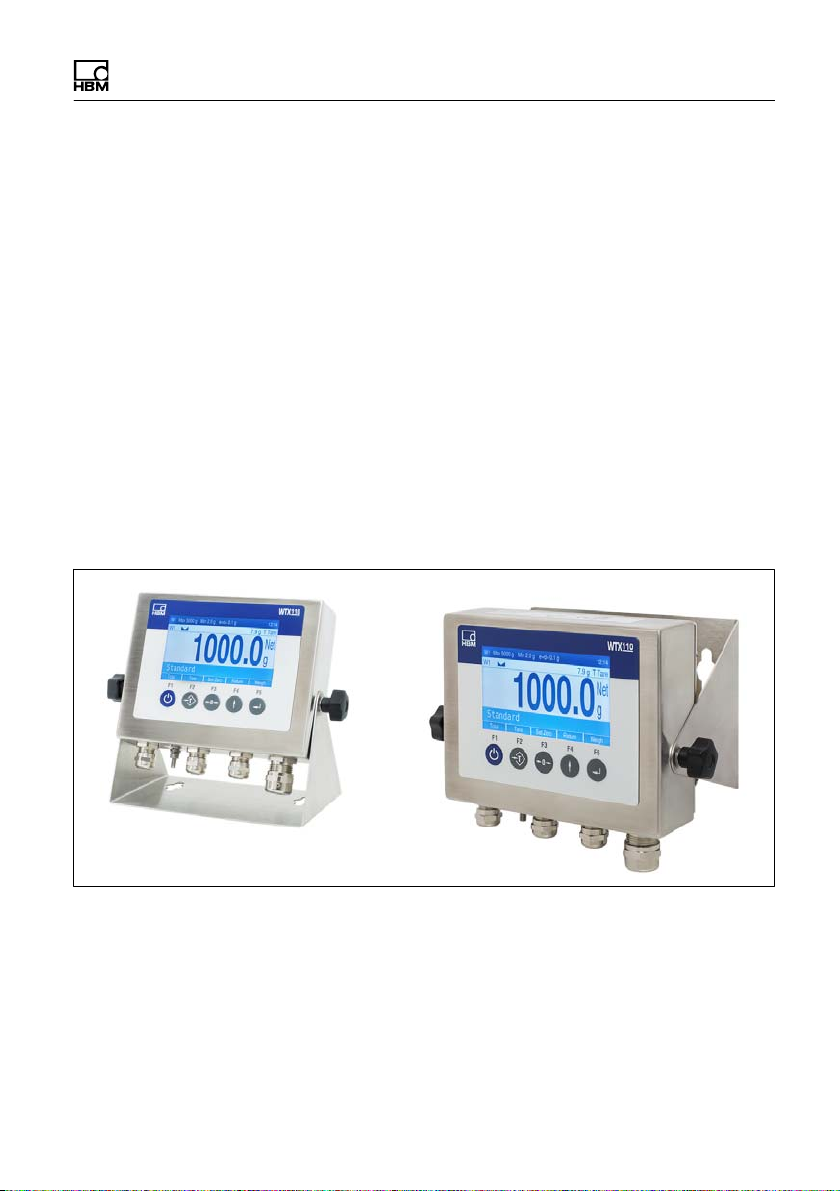
3 System description
The WTX110 weighing terminal is designed for universal use, for example in
weighing, recording and dosing systems.
Depending on the device variant, either analog SG load cells or specified digital
HBM sensors and electronics can be used.
Depending on the device variant, three power supplies are available
S 12 … 30 VDC
S 110 … 240 VAC
S External battery 12 … 30VDC (battery not included)
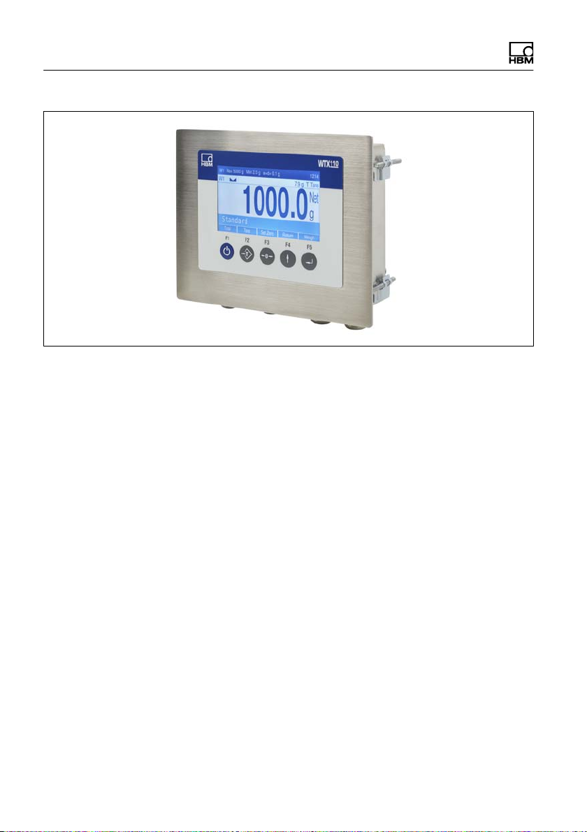
Two stainless steel housing variants (1) table / wall-mounting or panel
mounting are available. Both variants have IP protection rating IP69K (panelframe: front).
Fig. 3.1 Desktop and wall mounting
WTX110 A4774-1.0 HBM: public 17
Page 20
System description
Fig. 3.2 Panel mounting
The WTX110 can optionally be equipped with the following hardware options:
S Communications interfaces
- Ethernet TCP/IP interface (e.g. for PanelX, printer or firmware update)
- 2 x Digital Out, 1 x Digital In
- RS485 (4 wires) (e.g. for printer)
- RS232 (e.g. for incline sensor)
- USB2.0 (e.g. for printer, keyboard or firmware update)
S Analog or digital inputs/outputs
- 2 x Digital Out, 2 x Digital In
- 1 x analog output
S Legal for trade data storage 1,000,000
18 A4774-1.0 HBM: public WTX110
Page 21
System description
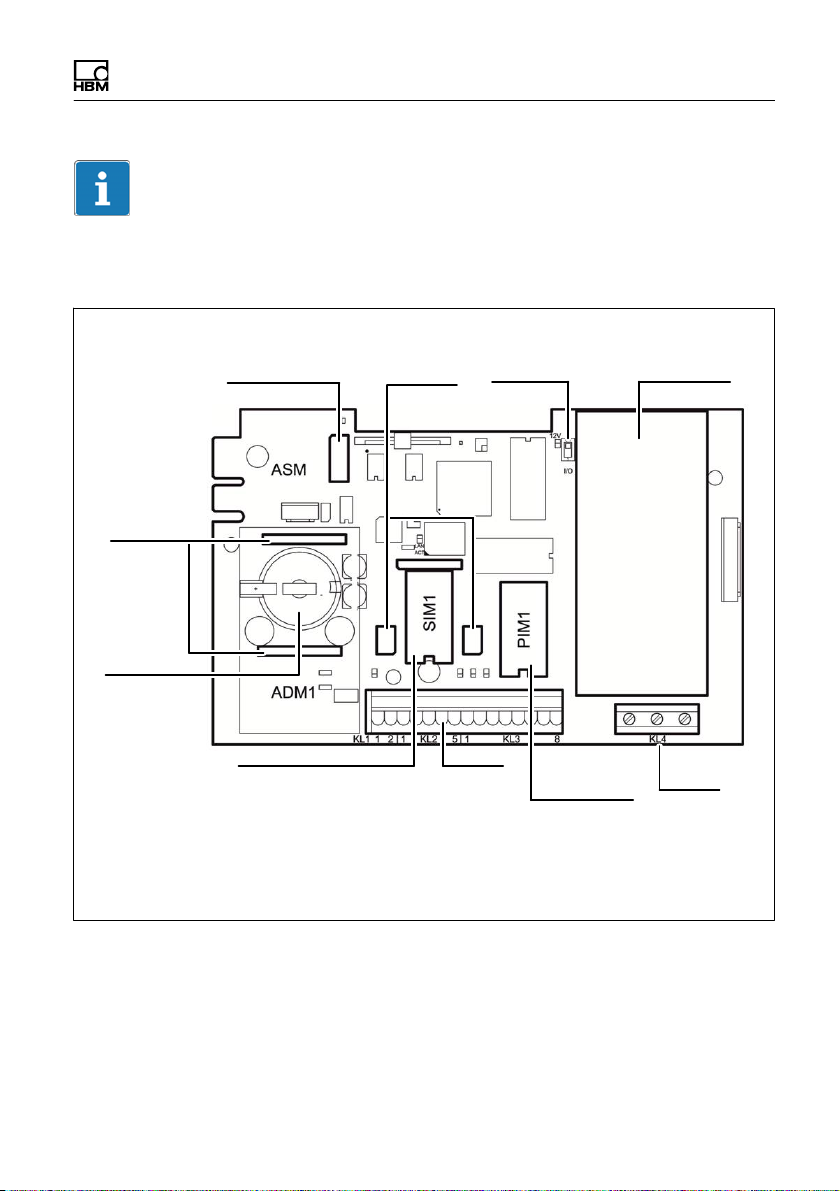
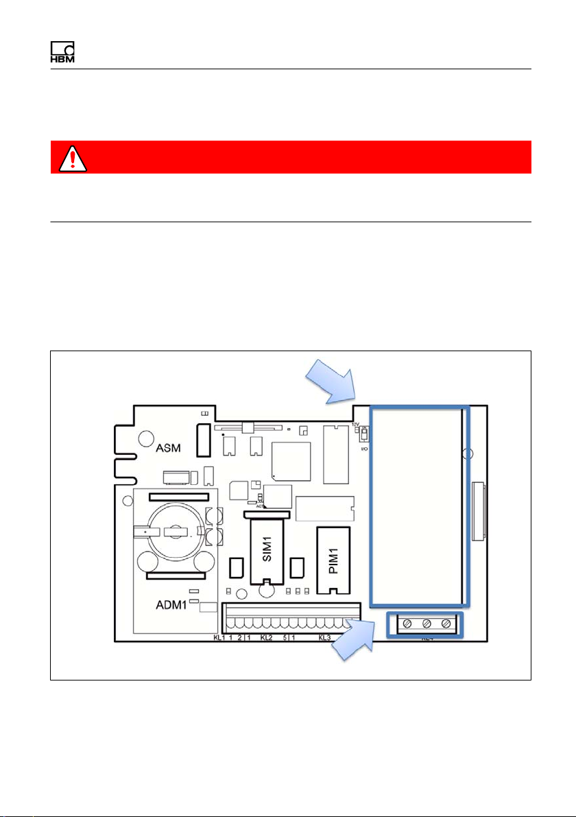
Important
Only one option can be selected at a time for communications interfaces and
analog or digital I/Os.
Scale
connection
of ADM,
DWB
Battery
CR2032
Slot for legal for
trade data storage
(ASM)
Slot for communications
interfaces Ethernet TCP/
IP, RS485-4, RS232
SIM USB
slot
S100 On/
Off key
Terminals
KL1-KL3 Power
Slot for analog
output or digital
I/Os PIM500,
DAU15
Power supply
12…30 VDC
110…240 AC
supply
For connecting different plug-in modules see section 4 "Installation," page 20.
WTX110 A4774-1.0 HBM: public 19
Page 22
Installation
4 Installation
4.1 Overview of connections
4.1.1 ADM (analog sensors)
ADM for analog sensors in slot ADM1
6 wires 4 wires
1 + Excitation 1 / 3 + Excitation
2 – Excitation 2 / 4 – Excitation
3 + Sense 5 + Signal
4 – Sense 6 – Signal
5 + Signal
6 – Signal
20 A4774-1.0 HBM: public WTX110
Page 23
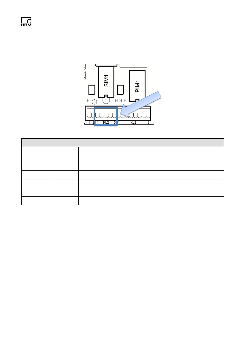
4.1.2 Serial interfaces
KL2: Serial interfaces RS485, RS232 in slot SIM1
ConnectionRS232 RS485 4 wires
1 TxD Tx A (Tx+)
2 RTS Tx B (Tx‒)
3 RxD Rx A (Rx+)
4 CTS Rx B (Rx‒)
5 Gnd -
Installation
WTX110 A4774-1.0 HBM: public 21
Page 24
Installation
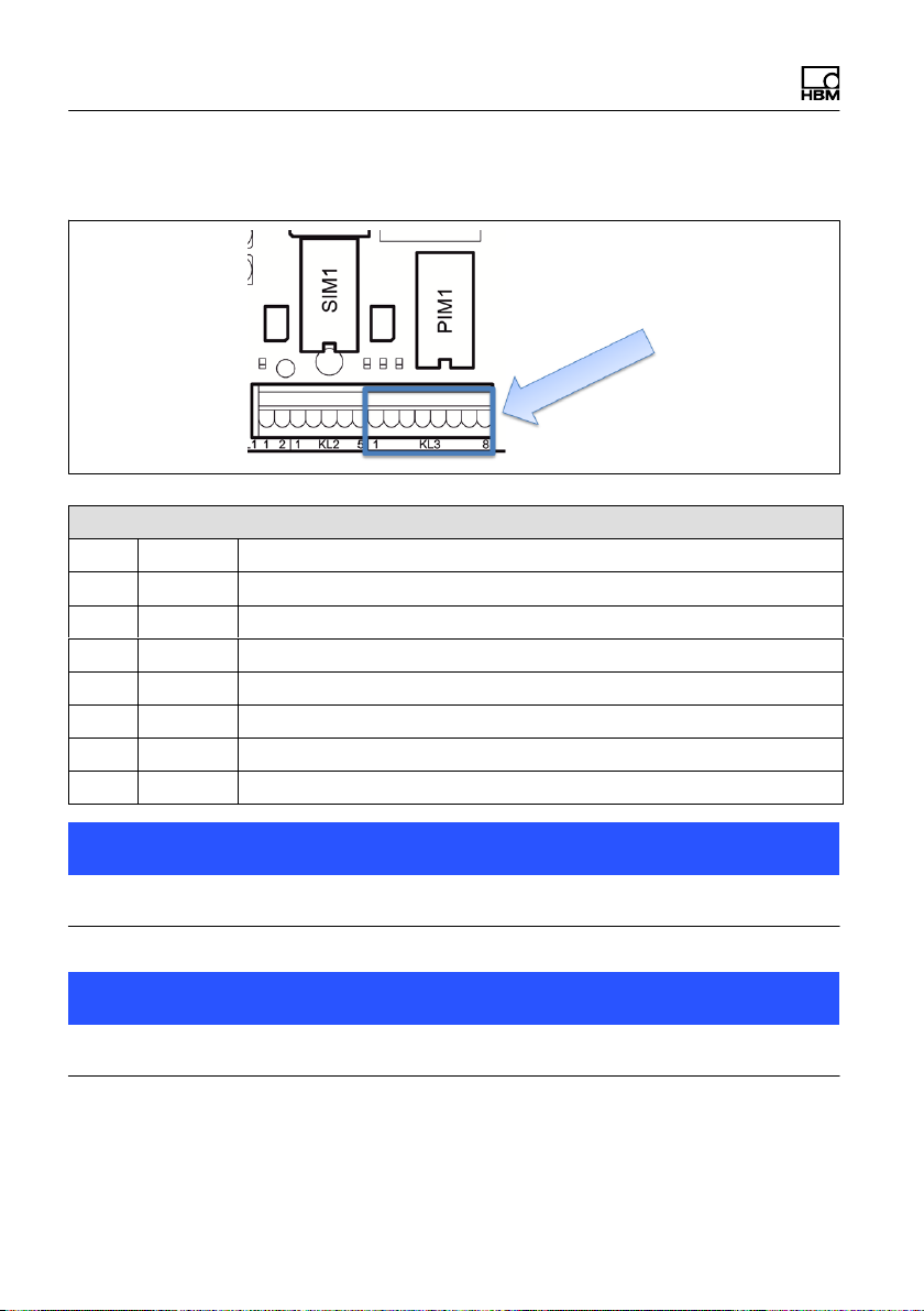
4.1.3 Digital inputs/outputs
KL3: Digital inputs/outputs PIM500 in slot PIM1
1 (=0 V) Power supply for external peripheral devices (digital load cells, etc.)
2 (=+12 V) Power supply for external peripheral devices (digital load cells, etc.)
3 IN 0
4 IN 1
5 IN ‒ PIM500: for IN 0, IN 1 and OUT 0, OUT 1
6 OUT 0
7 OUT 1
8 OUT + for OUT 0, OUT 1
Notice
Load carrying capacity of outputs max. 500 mA at 12…24 VDC.
Notice
Current consumption of inputs max. 7 mA at 12…24 VDC.
22 A4774-1.0 HBM: public WTX110
Page 25
KL2: Digital inputs/outputs SIO in slot SIM1
1 OUT 0
2 OUT 1
3 OUT + For OUT 0 … OUT 1 and IN 0
4 IN 0
5 - Must stay clear
Installation
Notice
Load carrying capacity of outputs max. 100 mA at 12–24 VDC.
Notice
Current consumption of inputs max. 7 mA at 12–24 VDC.
WTX110 A4774-1.0 HBM: public 23
Page 26
Installation
4.1.4 Analog output
KL3: Analog output DAU15 in slot PIM1
1 2 3 I + Current output 0/4–20 mA (+)
4 I – Current output 0/4–20 mA (–)
5 6 U + Voltage output 0/2–10 V (+)
7 U – Voltage output 0/2–10 V (–)
8 -
4.2 Setup and installation
The operating temperature can be between –10 °C and +40 °C with 95 %
relative humidity (non-condensing). Avoid direct sunlight
For wall-mounting the device is first mounted on the wall and then the cables
are connected with the housing cover open.
There are six fastening clamps on the device for control cabinet mounting.
Before commissioning the housing must always be closed and screwed shut
with the hexagonal nuts included with delivery. The hexagonal nuts must be
tightened crosswise to a torque of 1.1 Nm.
24 A4774-1.0 HBM: public WTX110
Page 27
Installation
4.3 Mains connection
DANGER
Danger of death! it is absolutely necessary to read the General safety instruc
tions chapter before making the mains connection!
The WTX110 is available for connection in three variants:
S Alternating voltage systems K-WTX110-*-AC*-**-***-**-***-**
S DC voltage systems K-WTX110-*-DC/-**-***-**-***-**
S External batteries K-WTX110-*-BA/-**-***-**-***-**
Power supply
unit
Power supply
The power supply is connected to terminal 4.
WTX110 A4774-1.0 HBM: public 25
Page 28
Installation
The device power supply must not simultaneously supply machines or
equipment that cause grid interference (motors, relays, heaters, etc.). Even
brief surges or drops in the voltage supply can adversely affect how the device
functions or lead to damage. An uninterruptible power supply (UPS) or voltage
stabilizer can prevent this.
The device must be incorporated into the potential equalization of the system.
There is a threaded bolt on back for this purpose.
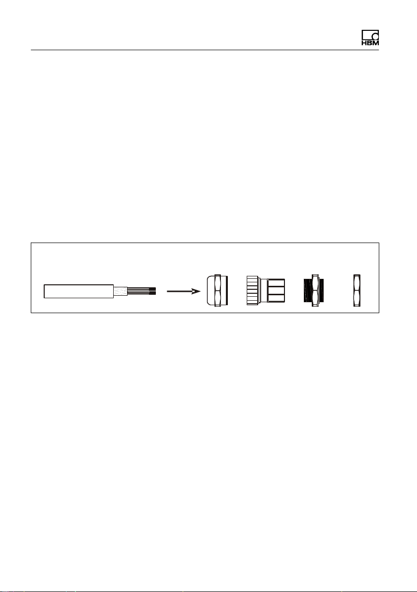
4.4 General cable assembly
All connection cables are directed through the bolted cable connection on the
bottom of the device to the inside of the housing.
Cable sheath Shield Swivel nut Plastic
insert
Metal
housing
Check
nut
► Slide the swivel nut over the cable sheath.
► Push the plastic insert over the cable sheath until the right edge of the
insert meets the end of the cable sheath.
► Unbraid the shield and lay it as flat as possible over the right part of the
plastic insert so that the shield is conductively connected with the housing.
The shield wires must not be longer than the right part of the insert.
Otherwise the bolted cable connection no longer provides a reliable seal.
26 A4774-1.0 HBM: public WTX110
Page 29
Installation
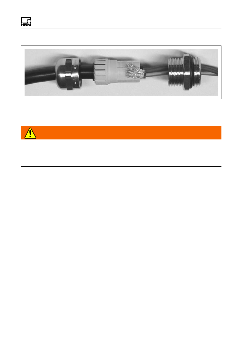
► Guide the cable with plastic insert into the metal housing.
► Screw on the swivel nut and tighten it with a screwdriver.
WARNING
Cut the individual wires to length so that the parts conducting mains voltage
(connection cable, power supply unit) cannot touch! Use wire end ferrules for
leads with fine wires and make certain no individual wires are sticking out.
4.5 Connection of analog SG sensors
The WTX110-A permits the connection of analog SG sensors with the following
specification:
S Maximum 8 SG load cells with 350 Ω each
S Load cell impedance range 43 Ω ... 3321 Ω
S Legal for trade weight resolution 10.000 e, internal 524.000 d
S Smallest permissible input signal for legal for trade applications: 0.33 μV/e
S Sample rate 50–800 measurements / second (can be adjusted in Service
mode)
S Supply voltage for load cells: 5 V ±5 %, clocked
S Connection in 4- or 6-wire configuration
WTX110 A4774-1.0 HBM: public 27
Page 30
Installation
Tip
Use a suitable terminal box to connect multiple load cells, for example types
VKK1-4 or VKK2-8 from HBM, for wiring the load cells.
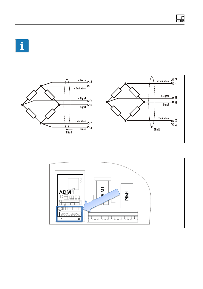
6-wire configuration of load cell 4-wire configuration of load cell
Fig. 4.1 Schematic diagram of load cell with 6- and 4-wire configuration
Fig. 4.2 Connection of an analog SG sensor in 6-wire configuration to the ADM
module
28 A4774-1.0 HBM: public WTX110
Page 31

Installation
ADM for analog sensors in slot ADM1
6 wires 4 wires
1 + Excitation 1 / 3 + Excitation
2 – Excitation 2 / 4 – Excitation
3 + Sense 5 + Signal
4 – Sense 6 – Signal
5 + Signal
6 – Signal
Connection of an analog SG sensor in 4-wire configuration to the ADM
module
To operate sensors without sense wires (4-wire mode), jumpers must be fitted
on terminal TE1 between pins 1 and 3 and 2 and 4.
4.5.1 Connection cable for analog load cell
When laying scale connecting cables (analog load receptors) please note:
S Use only suitable scale connecting cables:
WTX110 A4774-1.0 HBM: public 29
Page 32

Installation
- Keep to the rated voltages of the connecting cable.
- Double-shielded cable is advantageous (braided shield)
- The length and cross-section of the individual wires must meet the
following conditions:
Cable length (m) / cross-section (mm@) v270 (m/mm@)
- Maximum line length between load cells and weighing terminal: 200 m
S The shield of the load cell cable must be fitted across a large area all-round
in the screwed cable gland of the weighing terminal. This can be done with
all WTX110 variants. An additional connection for potential equalization is
located on the bottom of the WTX110.
S The load cells and load receptors, terminal boxes and weighing terminal
must be integrated into the equipotential bonding system. To do this,
depending on the local conditions, it may be necessary to lay a separate
equipotential bonding line with a corresponding cross-section (e.g. 16mm@).
S Use only metal terminal boxes to extend cables, and fit the shielding for
both cables in the screwed cable glands.
S Cable laid a minimum of 50 cm away from power lines. Lay cable in
grounded steel conduit, metal tubing or metal cable ducts.
S When load cells are under tension rather than compressive load, the +
and – signal connections must be swapped.
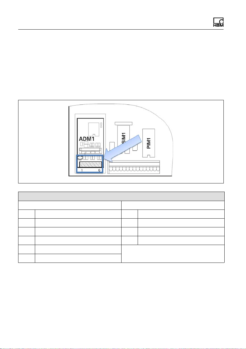
4.5.2 Saving calibration data for legal for trade applications
The calibration data can be saved on the ADM motherboard with jumper W1.
In the factory settings W1 is always set to calibration enabled!
30 A4774-1.0 HBM: public WTX110
Page 33

Installation
Calibration data saved:
Jumper set
Enable calibrating and saving: Jumper in
this position or completely removed
Information
Not removing the W1 jumper completely, or only removing it for replugging and
proceeding with care when moving the jumper is recommended to prevent the
jumper from being lost!
When setting the jumper, take care to ensure it is set on both pins to ensure
reliable calibration.
WTX110 A4774-1.0 HBM: public 31
Page 34

Installation
The position of the W1 jumper can be locked by a
weights and measures officer with thread and lead or a
seal:
A description of calibration can be found in section 11
"Calibration," page 159!
4.6 Serial interface connection
The WTX110 generally ships with the variant configuration with pre-wired
options.
RS232 or RS485 (4-wire) can be selected as serial options. The serial interface
module is always plugged into slot SIM1.
Fig. 4.3 Positioning the serial module on the WTX110 motherboard (CPU1)
32 A4774-1.0 HBM: public WTX110
Page 35

The connection is via terminal KL2 serial 1-5.
KL2: Serial interfaces RS485, RS232 in slot SIM1
Connection RS232 RS485 4 wires
1 TxD Tx A (Tx+)
2 RTS Tx B (Tx‒)
3 RxD Rx A (Rx+)
4 CTS Rx B (Rx‒)
5 Gnd -
Installation
Transfer lines connecting the serial ports must be installed so that inductive
and capacitive interference from other lines, machines or electrical devices is
ruled out. Interference on data transfer could result in delays or in the program
stopping.
To ensure optimal interference suppression of all injected frequencies, the
shield should be applied on both sides.
In the event of fluctuations in ground potential, a compensating current may
flow via the double-side shield. In this case an additional equipotential bonding
line must be laid.
WTX110 A4774-1.0 HBM: public 33
Page 36

Installation
Important
Terminal designation: Some manufacturers of components with RS485 ports
designate the terminals differently. According to the standard, the TxD+ / RxD+
port is designated 'B' and the TxD– / RxD– port 'A'.
Important
Cable: Always use twisted-pair cables! The surge impedance of the cable
should be approximately 150 W.
When laying cables for serial interfaces please note:
S Transfer lines connecting the serial ports must be installed so that inductive
and capacitive interference from other lines, machines or electrical devices
is ruled out. Interference on data transfer could result in delays or in the
program stopping.
S Self-wired cables must meet the following specification:
Shielded with twisted pairs, for example LIYCY 3 x 2 x 0.14 mm@ or LIYCY 3 x 2 x
0.25 mm@; shielded applied on both side
Cable resistance ≤ 125 Ω/km
2
Conductor cross-section ≥ 0.14 mm
Line capacitance ≤ 130 nF/km
Cable length, RS232 max. 15 m
Cable length, RS485 max. 1200 m
Characteristic impedance of RS485 approx. 150 Ω
Nominal (rated) voltage of the cable ≥ 250 V
to 200 m, ≥ 0.25 mm2 to 1200 m
34 A4774-1.0 HBM: public WTX110
Page 37

Installation
4.7 USB connection
If a WTX110 is ordered with a USB connection, the USB connection is
completely pre-wired. Devices can be connected via USB connector socket
type A on the bottom of the device.
4.8 Ethernet TCP/IP connection
If a WTX110 is ordered with an Ethernet connection, the Ethernet connection
is completely pre-wired. Devices can be connected via M-12 socket on the
bottom of the device.
An HBM connection cable can be used for the connection to local 10/100-Mbit
Ethernet networks.
S 1-KAB2129-5: Ethernet connection cable M12 plug to RJ45 plug (straight)
(5 m)
S 1-KAB2130-5: Ethernet connection cable M12 plug (90°) to RJ45 plug (5 m)
S 1-KAB2129-10: Ethernet connection cable M12 plug to RJ45 plug (straight)
(10 m)
S 1-KAB2130-10: Ethernet connection cable M12 plug (90°) to RJ45 plug
(10 m)
Information
Cable length without repeater (hub/switch) max. 80 m
WTX110 A4774-1.0 HBM: public 35
Page 38

Installation
4.9 Digital inputs/outputs
Depending on the configuration of the relevant variant, the WTX110 has a
maximum of three digital inputs and four digital outputs on the device. It is also
possible to connect up to four digital inputs and 4 digital outputs via a Modus/
TCP fieldbus coupler (for example Wago 750-342). See chapter 4.9.2.
There are two independent options available for digital I/Os, (1) IO and / or (2)
DIO
K-WTX110-*-***-**-***-IO-***-**
2x DO and 2 x DI
Information
If the IO option is selected, no additional interfaces can be used on this option!
K-WTX110-*-***-**-DIO-** -***-**
2 x DO and 1 x DI
Information
If the DIO option is selected, no additional interfaces can be used on this
option!
In the maximum configuration level no additional options such as Ethernet
TCP/IP, USB or an analog output are possible.
If a WTX110 is ordered with option "IO" and / or "DIO", the interface is
completely pre-wired. The IO option is always used in slot PIM1, DIO always in
SIM1.
36 A4774-1.0 HBM: public WTX110
Page 39

Installation
4.9.1 Overview I/O Connection
Settings at the WTX110 Config 1 Config. 2 Config. 3
Group 1
(Config.->Digital I/O)
Group 2
(Config.->Digital I/O)
Number of outputs 2 2 4
Number of inputs 1 2 3
Output 1 KL2-OUT0 KL3-OUT0 KL3-OUT0
Output 2 KL2-OUT1 KL3-OUT1 KL3-OUT1
Output 3 na na KL2-OUT0
Output 4 na na KL2-OUT1
Input 1 KL2-IN0 KL3-IN0 KL3-IN0
Input 2 na KL3-IN1 KL3-IN1
Input 3 na na KL2-IN0
Input 4 na na na
SIO
see
Tab. 4.2
Overview of terminalblocks
PIM
see
Tab. 4.1
PIM
see
Tab. 4.1
SIO
see
Tab. 4.2
WTX110 A4774-1.0 HBM: public 37
Page 40

Installation
4.9.2 Overview I/O Connection with Ethernet (Modbus-TCP) Fieldbus coupler
Settings at the WTX110 Config 4 Config. 5
Group 1
(Config.->Digital I/O)
Group 2
(Config.->Digital I/O)
Number of outputs 4* 4*
Number of inputs 4* 4*
Output 1 KL2-OUT0 MTCP-Output 1
Output 2 KL2-OUT1 MTCP-Output 2
Output 3 MTCP-Output 1 MTCP-Output 3
Output 4 MTCP-Output 2 MTCP-Output 4
Input 1 KL3-IN0 MTCP-Input 1
Input 2 KL3-IN1 MTCP-Input 2
Input 3 MTCP-Input 1 MTCP-Input 3
Input 4 MTCP-Input 2 MTCP-Input 4
PIM Modbus/TCP
Modbus/TCP -
Overview of terminalblocks
38 A4774-1.0 HBM: public WTX110
Page 41

Installation
4.10 Connection of digital inputs/outputs IO (2xDO, 2xDI)
If a WTX110 is ordered with option "IO," the interface is completely pre-wired.
K-WTX110-*-***-**-***-IO-***-**
The IO option is always used in slot PIM1 and labeled with PIM500.
Notice
Load carrying capacity of outputs max. 500 mA at 12…24 VDC.
Notice
Current consumption of inputs max. 7 mA at 12…24 VDC.
Fig. 4.4 Positioning of the IO module (PIM500) on the WTX110 motherboard
WTX110 A4774-1.0 HBM: public 39
Page 42

Installation
Fig. 4.5 Connection of digital inputs/outputs to KL3
KL3: Digital inputs/outputs PIM500 in slot PIM1
1 (=0 V) Power supply for external peripheral devices (digital load cells, etc.)
2 (=+12 V) Power supply for external peripheral devices (digital load cells, etc.)
3 IN 0
4 IN 1
5 IN ‒ PIM500: for IN 0, IN 1 and OUT 0, OUT 1
6 OUT 0
7 OUT 1
8 OUT + for OUT 0, OUT 1
Tab. 4.1 KL3: Digital inputs/outputs OIM500 in slot PIM1
Notice
Maximum current consumption on KL3 (terminal 1 and 2) according to section
4.13 "Power supply for external peripheral devices".
40 A4774-1.0 HBM: public WTX110
Page 43

Installation
4.11 Connection of digital inputs/outputs DIO (2xDO, 1xDI)
If a WTX110 is ordered with option "DIO," the interface is completely pre-wired.
K-WTX110-*-***-**-DIO-**-***-**
The DIO option is always used in slot SIM1 and labeled with SIO. It has one
optically isolated input and two optically isolated outputs.
Notice
Load carrying capacity of outputs max. 100 mA at 12–24 VDC.
Notice
Current consumption of inputs max. 7 mA at 12–24 VDC.
Fig. 4.6 Positioning of the DIO module (SIO) on the WTX110 motherboard
WTX110 A4774-1.0 HBM: public 41
Page 44

Installation
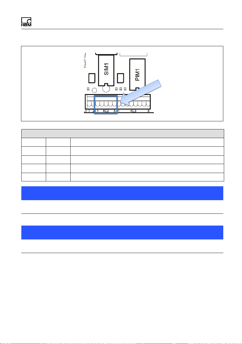
The connection is via terminal KL2 serial 1-4.
KL2: Digital inputs/outputs SIO in slot SIM1
1 OUT 0
2 OUT 1
3 OUT + For OUT 0 … OUT 1 and IN 0
4 IN 0
5 - Must stay clear
Tab. 4.2 KL2: Digital inputs/outputs SIO in slot SIM1
Information
In contrast to the digital inputs of the IO module, the input of the DIO module is
inverted! A logical 1 is detected if the input is connected to ground potential.
See the schematic circuit diagram below.
42 A4774-1.0 HBM: public WTX110
Page 45

Installation
Digital output Digital input
Fig. 4.7 Schematic circuit diagram of DIO module
4.12 Connection of 15-bit analog output
If a WTX110 is ordered with option "AO," the interface is completely pre-wired.
K-WTX110-*-***-**-***-AO-***-**
Depending on the relevant variant of the device, the WTX110 is fitted with an
analog output in slot PIM1 and labeled with DAU15. A plug-on module
(DAU15) can be used to indicate gross or net weights via a 15-bit analog
output.
WTX110 A4774-1.0 HBM: public 43
Page 46

Installation
Fig. 4.8 Positioning of the AO module (DAU15) on the WTX110 motherboard
The resolution of the analog output signal (gross or net weight) is 15 bits
(32,768 increments). The output signal is active and potential-free.
The AO module (DAU15) is in Service mode/Config.Config. The Analog Out
group 'DAU15' can optionally be adjusted to 0/2…10 V or 0/4…20 mA. The
resolution of the analog output signal is 15 bits (32,768 increments). The
output signal is active and potential-free.
Information
The AO module must be always calibrated.
44 A4774-1.0 HBM: public WTX110
Page 47

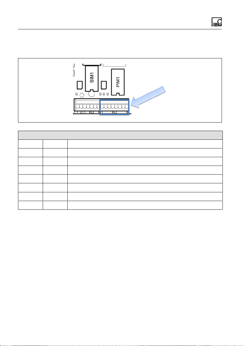
Fig. 4.9 Connection of analog output to KL3
KL3: Analog output
1
2
3 I+ Current output 0/4–20 mA (+)
4 I‒ Current output 0/4–20 mA (–)
5
6 U+ Voltage output 0/2–10 V (+)
7 UI‒ Voltage output 0/2–10 V (–)
8
Installation
WTX110 A4774-1.0 HBM: public 45
Page 48

Installation
KL3
Fig. 4.10 Example of connection for current output 0/4–20 mA
500 ohms max.
KL3
500 ohms min.
Fig. 4.11 Example of connection for voltage output 0/2-10 V
46 A4774-1.0 HBM: public WTX110
Page 49

Installation
4.13 Power supply for external peripheral devices
12 V is provided on terminals KL1 (terminals 1, 2) and KL3 (terminal 1, 2) as
the power supply for peripheral devices (digital load cells, etc.).
Terminal 1 2
KL 1 0 V (=+12 V)
KL 3 0 V +12 V
Maximum current consumption
ADM installed in slot ADM1 (with up to 8 analog load cells, 350 ohms each):
Current consumption
of USB device
0…100 mA 300 mA max.
100…300 mA 200 mA max.
300…500 mA 100 mA max.
Current consumption 12 V for peripheral devices on KL1
and KL3 (total)
WTX110 A4774-1.0 HBM: public 47
Page 50

Installation
4.14 Connection to 110 … 240 VAC
All K-WTX110-*-AC*-**-***-**-***-** variants have a power supply unit for alter
nating voltages in the range from 110 V (–15 %) to 240 V (+10 %), 50/60 Hz.
The input side is protected by a safety fuse (2 A slow-blow). The mains
connection is made with the mains cable, which is connected to terminal KL4
at the time of delivery (length 2.5 m) with a VDE plug or selected mains plug.
KL4: Power supply
1 PE
2 N
3 L1
48 A4774-1.0 HBM: public WTX110
Page 51

Installation
Information
Depending on the relevant variant of the device, mains connector plugs are
available for Europe, US, UK, Switzerland, South Africa and Australia, etc.
pre-wired and having passed the relevant electrical tests.
Potential equalization is pre-wired for the housing and cover.
DANGER
Parts of the power supply unit conduct high, life-threatening voltages during
operation! A faulty power supply unit cannot be repaired! The device must be
returned to HBM!
WTX110 A4774-1.0 HBM: public 49
Page 52

Installation
4.15 Connection to 12…30 VDC
All K-WTX110-*-DC/-**-***-**-***-** variants have a power supply unit (DCB)
that operates with DC voltage in the range from 12 VDC (–15 %) to 30 VDC
(+10 %). The connection is via terminal KL4. Power supply.
KL4: Power supply
1 PA
2 0 VN
3 +V
4.16 Connection to external battery 12…30 VDC
All K-WTX110-*-BA/-**-***-**-***-** variants have a power supply unit (NTB) for
input DC voltages in the range from 12 VDC (*15 %) to 30 VDC (+10 %). The
device is suitable for connecting to an external battery. It has voltage
monitoring with automatic shut-off. The external battery is connected to
terminal KL4.
50 A4774-1.0 HBM: public WTX110
Page 53

KL4: Power supply.
1 PA
2 0 VN
3 +V
Installation
If the WTX110 is powered by an external battery, the type must be selected in
'\Service\General\Power supply.' The effect of this selection on the automatic
shut-off behavior of the terminal is as follows:
WTX110 A4774-1.0 HBM: public 51
Page 54

Installation
Parameters Type Low batt. (volts)
(flashing battery
symbol beginning at
about)
Pb12 12 V lead
rechargeable
battery
Pb24 24 V lead
rechargeable
battery
Adjust Any recharge
able battery
Line Mains operation - -
11.5 V 11 V
23 V 22 V
Adjustable Adjustable
Power off (volts)
(shutdown at about)
If there is only a little remaining capacity (Low batt) the user is alerted by a
flashing battery icon in the top right corner of the display that the rechargeable
battery must be charged.
To prevent deep discharge of the connected rechargeable battery, the terminal
automatically switches off at the set voltage (Power off). If the terminal is
turned on again with the rechargeable battery deeply discharged, a message
appears indicating 'Low Battery: Power off' and the terminal switches off again.
4.17 Legal for trade data storage/alibi memory
If a WTX110 with the ALI option was ordered, the legal for trade memory is
completely pre-wired and plugged into the ASM slot. It is used for storing the
last 1,000,000 weighing processes.
K-WTX110-*-***-**-***-**-ALI-**
52 A4774-1.0 HBM: public WTX110
Page 55

Fig. 4.12 Positioning of ALI option on the WTX110 motherboard
Installation
WTX110 A4774-1.0 HBM: public 53
Page 56

Installation
4.18 Activating the On/Off key
Fig. 4.13 Switches S100
Switch S100 on the WTX110 motherboard is used to configure the function of
the On/Off key (F1):
ON position (default) On/Off key deactivated
The weighing terminal starts immediately as soon as current
is supplied.
Position 1 On/Off key activated
The weighing terminal does not start until the On/Off key is
activated. Activating the key again turns the weighing
terminal off.
About 1 minute is required to start the device. The device shows the text:
System Startup ...
Please wait!
54 A4774-1.0 HBM: public WTX110
Page 57

Operator control/settings
5 Operator control/settings
5.1 Service password
The Service password provides access to the Service mode.
The default Service password is 324.
1 234OK
The numbers are shown on the WTX110 display by the softkeys.
The Service password cannot be changed.
WTX110 A4774-1.0 HBM: public 55
Page 58

Operator control/settings
5.2 Display and control elements
Scale no./
weighing range no.
Scale stand
still symbol
Gross weight
or net weight
(Net)
Scale no.
Maximum
load
Minimum
load
Scale interval e
division d
Tare value
Time
Fig. 5.1 WTX110 display
Electronic typeplate
(only for single and dual range/two scale division scales)
Meaning Display Description
Scale no. W1 Always 1
Maximum load For example:
Max 5000 kg
Minimum load For example:
Min 2 g
Upper weighing range limit (without addi
tive tare), adjustable In calibration mode
Lower weighing range limit
Electronic
typeplate
Net display
symbol
Unit
Operator guidance
display
Softkeys
Function keys
56 A4774-1.0 HBM: public WTX110
Page 59

Operator control/settings
DescriptionDisplayMeaning
Scale interval e /
division d
12:14 PM Time display
For example:
e=d=0.1 g
Legal for trade scale division – scale
division e and display increment
scale interval d (in most cases e is the
same as d)
Information
The electronic typeplate is hidden with the setting in 'Service
Mode\Calibration\Adaptation\Onscreen typeplate=N' or for certain types of
scales (which ones?).
Weight indicator
Meaning Display Description
Scale no. W1 Scale no. selected with the scale toggle
key
Weighing range no. W1.1 … W1.3 Partial weighing range for multi-range
weighing machines
Scale standstill
symbol
Zero symbol >0< Scale is stopped in gross zero range
Tare 7.9 g T Display of tare weight
Gross weight or net
weight
Net display symbol Net Scale is tared
Unit For example g Weight unit, adjustable in calibration
For example 1250
For example
1000.0 g Net
Weight stabilized (printing/saving
possible)
(±0.2 d)
Switch between legal for trade gross
weight / net weight with Tare key
mode
WTX110 A4774-1.0 HBM: public 57
Page 60

Operator control/settings
Entry confirmation/function selection
Normally every entry or parameter/selection function must be confirmed with
the Enter key, even if it does not appear in the text. Then the program
continues in the next step.
Softkeys
The assignment of softkeys depends on the current program step as well as
the selected application. The current assignment is displayed in the bottom line
on the screen by the function keys.
Function keys
Key Softkey Description
On/Off Turn On/Off (if S100 in position 1)
Select Scroll forward / adapt parameters, call Service mode with
vibration notice
Clr Press: Delete characters individually
Hold: Clear all places
Tare Tare (tare balance), or clear tare of tared scale (multiple
taring also possible)
+1 Selection menu options or select values in a parameter
entry (+1)
Yes Activate an option
=> Scroll by character
Zero balance Zero gross weight of scale (only in range of zero setting)
0 Append 0 in parameter entries (0)
No Deactivate an option
Return
Return to the previous program step
Confirm
Confirm the parameter entries or continue to the next
program step (Enter)
58 A4774-1.0 HBM: public WTX110
Page 61

Operator control/settings
5.3 Example of entries via WTX110 display keys
The following sections explain the operator control sequence based on the
displayed user guidance texts and the corresponding entries.
The displays are shown on the left-hand side.
The following sections present examples of the input of alphanumeric
characters and numbers.
5.3.1 Alphanumeric entry
The following explains how the character string E1c can be entered based on
the example of an FTP password entry.
Display Key Description of key function
FTP pwd:
FTP pwd:A Hold to change entry mode.
The entry switches between:
A =upper case
a =lower case
0 =numbers and special characters
FTP pwd:E Keep pressing until the desired letter appears, e.g. E
FTP pwd:EA Press to create a new digit position
FTP pwd:E0 Hold to change entry mode.
FTP pwd:E1 Hold to change entry mode,
e.g. 1
FTP pwd:E10 Press to create a new digit position
WTX110 A4774-1.0 HBM: public 59
Page 62

Operator control/settings
Description of key functionKeyDisplay
FTP pwd:E1a Hold to change entry mode.
FTP pwd:E1c Keep pressing until the desired letter appears, e.g. c
FTP pwd:E1c Apply value
Information
The CLR key is used to clear individual characters.
5.3.2 Entering whole numbers
The following explains how to enter a sequence of digits.
Here for example the sequence 123.
Display Key Description of key function
Terminal No.: 001
Terminal No.: 0
Terminal No.: 1
Terminal No.: 10
Terminal No.: 12
Clear all places
Keep pressing until the desired digit appears, e.g. 1
Press to create a new digit position
Keep pressing until the desired digit appears, e.g. 2
60 A4774-1.0 HBM: public WTX110
Page 63

Operator control/settings
Description of key functionKeyDisplay
Terminal No.: 120
Terminal No.: 123
Terminal No.: 123 Apply value
Press to create a new digit position
Keep pressing until the desired digit appears, e.g. 3
Information
The F1 key is used to clear individual characters.
WTX110 A4774-1.0 HBM: public 61
Page 64

Operator control/settings
5.3.3 Entering numbers with decimal places
The following explains how to enter a sequence of digits with decimal places.
Here for example the sequence 0.001.
Display Key Description of key function
Interval 0.321
Interval 0.000 Clear all places
Interval 0.001 Keep pressing until the desired digit appears, e.g. 1
Interval 0.010 Press to move the digit one position to the left.
Interval 0.012 Keep pressing until the desired digit appears, e.g. 2
Interval 0.120 Press to move the digit one position to the left.
Interval 0.123 Keep pressing until the desired digit appears, e.g. 3
Interval 1.230 Press to move the digit one position to the left.
Interval 1.234 Keep pressing until the desired digit appears, e.g. 4
Interval 1.234 Apply value
62 A4774-1.0 HBM: public WTX110
Page 65

Operator control/settings
5.4 Operating the weighing functions
The basic step for all processes is displaying the current continuous weight
value. In this step the basic weighing functions can be called and displayed.
A precondition for the following processes is the settings in Service mode:
'Print mode: Standard' and 'Auto Tare?=N.
See section 'Print mode' and 'Auto Tare'.
Further information is available from your supplier.
5.4.1 Tare functions
In Service mode, various tare functions can be assigned to the 'General' group.
A precondition for the following processes is the settings in Service mode:
'Print mode: Standard' and 'Auto Tare?=N.
Further information is available from your supplier.
5.4.2 Set / delete tare (Tare mode: Gross/Net)
Every time the Tare key is pressed, the display changes from Gross to Net and
back (setting 'Tare mode: Gross/Net'). This is the usual tare function, which is
suitable for most applications.
Display Key/Action Description
8.0 kg Set container in place
Tare
WTX110 A4774-1.0 HBM: public 63
Page 66

Operator control/settings
DescriptionKey/ActionDisplay
0.0 Net/kg
Delete tare
5.4.3 Automatic deletion of tare (Tare mode: Auto Clear)
The loaded scale can be tared one time. If the scale is completely unloaded,
the tare is automatically deleted and the display switches back to Gross.
This function is provided for series of weighings with identical tare weight.
Display Key/Action Description
8.0 kg Set container in place
13.0 Net/kg Article in container
-8.0 Net/kg Remove full container from the scale
64 A4774-1.0 HBM: public WTX110
Page 67

Operator control/settings
5.4.4 Repeated taring (Tare mode: Net=0)
Every time the Tare key is pressed, the scale is tared again and the display
shows the net weight. If the scale is completely unloaded, the tare is automati
cally deleted and the display switches back to Gross.
This function is used when multiple components will be weighed one after the
other in the same container.
Display Key/Action Description
8.0 kg Set container in place
0.0 Net/kg
Taring...
13.0 Net/kg 1st article in container
13.0 Net/kg
Weighing...
0.0 Net/kg
Taring...
13.0 Net/kg 2nd article in container
13.0 Net/kg
Weighing...
Tare scale (Net is displayed)
Send weight value to printer / PC
Tare scale again
Send weight value to printer / PC
WTX110 A4774-1.0 HBM: public 65
Page 68

Operator control/settings
DescriptionKey/ActionDisplay
-8.0 Net/kg Remove full container from the scale
5.4.5 Zeroing
Display Key/Action Description
0.2 kg
0.0 kg
Zeroing
Zero gross weight (only possible within the
selected range of zero setting).
5.4.6 Weighing
Display Key/Action Description
13.0 kg Article in container
13.0 kg
Weighing...
Send weight value to printer / PC
66 A4774-1.0 HBM: public WTX110
Page 69

Operator control/settings
5.4.7 Switch weight indicator to 10 times the resolution
Information
Only possible if 'Totals? = N' is set in Supervisor mode.
Display Key/Action Description
13.0 kg Gross weight display
13.0 kg
Net(X) 13.03 kg
Display of the current weight with 10 times
higher resolution.
After about 5 seconds the display
automatically disappears.
WTX110 A4774-1.0 HBM: public 67
Page 70

1 Service
Appl.
Master
2 Entry
Supervisor
Mode
Standard
WTX110 V#.#.#
< 3 seconds < 3 seconds
WTX110
Navigation Pilot
Password
Enter service
password
Com0 (Eth)
Port
Protocol
General
Date: Entry
Time: Entry
…
Brightness
Password
Baud
Databits
Parity
Ctrl.
Protcl.
Target weight
...
Filler configuration;
only available
in filler application
Com6 (DWB)Com1 (SIM1)
Baud
Databits
Parity
Ctrl.
Protcl.
Weight Storage Logbook Software IDProducts
Search Date
Id-No.
Weight not found
note: only if
ALI available
Language
Keyboard
Time Zone (1)
Time Zone (2)
Date (format only)
Time (format only)
Country Code
Decimal char.
Approval signs
Tare mode
Cont. out.
Light off (Min.)
Power off (Min.)
Power Supply
Serial No.
3_ ...
2_ ...
1_...
note: if „W1“ jumper
is in position 1
only access,
no changes possible
ID: ...
Calibrate Scale 1
Mastermode
note: alternative
access
MAC-/IP-Address
M:
IP:
only info
parameter
error protocoll,
only info
Config.
Scale
Config. Scale
Test Reset Network BackupGeneralInterface
Digital IO
Serial IO
Config.
Digital IO
Reset Service
Mode Parameters?
Reset
Approved Wgt
note: only if
ALI available
Config.
Analog out
IP
Mask
Gate
DNS
NTP
FTP pwd
PanelX access
Access number
Set PanelX password
Update SSL cert
Start auto ping
Terminal No.
Backup or
Restore
from USB
note: ETH
or USB option
required
General SetupCalibration
Application
note: after
change restart
required!
Language
LS1 – LS4 Source
LS1 – LS4 Mode
only available in
standard application
Digital IO Print FormatsLimit switches
Input 1 – 4
Output 1 – 4
Ticket Weight
Total Weight
Ticket Count
Total Count
Factory defaults
Load application
MastermodeApplicationService Mode
Mode: Info
(zero offset)
Mode: Adapt
(several
filter settings)
Map symbology
F2 F3 F4 F5
Two different possible entries
Entry field F1 button level
Subsequent field F1 button level
Related fields on F1 button level
Enter password / Unload Scale
Mastermode
F1
Click F1 button
Click respective grey button
Notes
exception: back to „Select Group 1 – 9“ with
not with the F1 button
Select Group 1 – 9
note: adapted parameters
must be saved to be valid!
ADM
HBM
None
Parameters
Single Range
One Interval
Capacity
Interval
Unit
PIM
Modbus TCP
SIO
None
2 Calibration 3 Linearization
Geo Value
Calibrate Zero?
Calibrate Load?
High Cap.
High Int.
Low Cap.
Low Int.
Unit
High Cap.
High Int.
Low Cap.
Low Int.
Unit
Non
DAU15
...
Aout 1: Mode
Aout 1: Output
Aout 1: Calibration
New Fixpoint 1? Motion Window
Triple RangeDual Range
High Cap.
High Int.
Mid Cap.
Mid Int.
Low Cap.
Low Int.
Unit
Three IntervalsTwo Intervals
High Cap.
High Int.
Mid Cap.
Mid Int.
Low Cap.
Low Int.
Unit
4 Zero Adjust 5 Adaption 6 High
Unload Scale
High Cap.
High Int.
Low Cap.
Low Int.
Unit
Motion Counter
Filter Size
Auto Zero Range
...
Incline Switch
PowerUp Zero
With Taring?
Underload
Update Rate
Three Intervals T+Two Intervals T+
High Cap.
High Int.
Mid Cap.
Mid Int.
Low Cap.
Low Int.
Unit
Resolution
Weight Reset Parameters? Calibrate Zero?
7 Reset 8 Calculation
note: only
calibration
Span
Zero (mV/V)
LC-Cap. (kg)
No. of LCs
mV/V of LC1
Quick Start Guide for Calibration Setup
1. Connect Sensor
2. go to “Calibration”\“1 Scale Parameters”
and enter load cell parameters like Capacity, Interval, Unit
3. Perform Calibration
- with Calibration Weight go to “2 Calibration”
- without Calibration Weight go to “8 Calculation Span”
4. Enter further parameters like Dual Range, Linearization, etc.
5.
Save Calibration Parameters
measure and predict with confidence
9 W&M Info1 Scale
W&M Setup ok
Page 71

Service mode
6 Service mode
To access the Service mode group select the following keys:
Menu Key Function
Standard Switch to version notice
WTX110V#.# Display the current firmware version number
Call password entry within 3 seconds
Password 324 Enter the password
1 Service mode Call Service mode
Servicemode is used to configure the weighing terminal. In addition to
configuration, Service mode includes function tests for the hardware and,
depending on the device variant (Ethernet TCP/IP, USB), the option for saving
data to a connected PC.
S Device variants for update:
- K-WTX110-A-***-**-ETH-**-***-**
- K-WTX110-A-***-**-USB-**-***-**
S The weighing terminal and connected peripheral devices may only be
configured and calibrated by qualified personnel!
S Before calling Service mode all peripherals should have been connected
and configured!
S To call Servicemode the Service password must be known.
S Inappropriate changes to settings in Service mode could result in
operational malfunctions!
WTX110 A4774-1.0 HBM: public 69
Page 72

Service mode
6.1 Configure interfaces (Interface )
For more information on the keys necessary to access this menu group, go to
the Navigation Pilot.
Information
The set values must match the setting of the corresponding peripheral devices.
6.1.1 Setting the Ethernet interface (interface: Com0 (Eth))
Menu Key Function/Secondary selection
Interface Com0 (Eth)
Com0: Port : 1234 Enter the port
Com0: Protocol AckNak Select the transfer protocol:
None Raw data only
TTY Printer control (data only)
AckNak Secure procedure with
acknowledgment
NoAck Secure procedure with
acknowledgment
→Protocol TTY selected
Com0: Codepage None Output character set:
None as per selected language
850 DOS code page 'Western Europe' for
older printers
852 DOS code page 'Central Europe'
866 DOS code page 'Russian'
Star DOS code page Star printer
70 A4774-1.0 HBM: public WTX110
Page 73

Service mode
→Protocol AckNak selected
Com0: Start char. 999 Enter the start character as a decimal value
(e.g. 2 = STX)
If you enter 0 no start character will be transferred
Com0: End char. 999 Enter the end character as a decimal value
(e.g. 3 = STX)
If you enter 0 no end character will be transferred
Com0: Checksum XOR Select checksum formation; the checksum is
transferred after the end character:
None No checksum
XOR Exclusive-Or combination
CPL Two's complement
→If start or end character entered and a checksum selected
Com0: With start N Start character is included in checksum formation
Com0: With end N End character is included in checksum formation
6.1.2 Setting the serial interface (interface: Com1 (SIM))
Menu Key Function/Secondary selection
Interface Com1 (SIM1)
Com1: Baud: 9600 Select the baud rate of the Com1 interface:
300, 600, 1200, 2400, 4800, 9600,
[19200], 38400, 57600, 115200
WTX110 A4774-1.0 HBM: public 71
Page 74

Service mode
Function/Secondary selectionKeyMenu
Com1: Data bits 8 Select the data format of the Com1 interface1:
7 7 data bits
8 8 data bits
1 stop bit is always transferred.
Com1: Parity None Select the parity for the Com1 interface:
None No parity
Even Even parity
Odd Odd parity
COM1: Contrl. None Select the send/receive control
(hardware handshake) of the Com1 interface:
XOn/Xoff Control by XON/XOFF
RTS/CTS Control with RTS/CTS
None No flow control
Notice: RTS/CTS not possible on Com2!
Com1: Protcl. None Select the transfer protocol of Com1:
None Raw data only
TTY Printer control (data only)
AckNak Secure procedure with
acknowledgment
NoAck Secure procedure with
acknowledgment
→Protocol TTY selected
Com0: Codepage None Output character set:
None ISO8869 as per selected language
850 DOS code page 'Western Europe' for
older printers
852 DOS code page 'Central Europe'
866 DOS code page 'Russian'
Star DOS code page Star printer
72 A4774-1.0 HBM: public WTX110
Page 75

Service mode
→Protocol AckNak or NoAck selected
Com1: Start char. 999 Enter the start character as a decimal value
(e.g. 2 = STX)
If you enter 0 no start character will be transferred
Com1: End char. 999 Enter the end character as a decimal value
(e.g. 3 = STX)
If you enter 0 no end character will be transferred
Com1: Checksum None Select checksum formation; the checksum is
transferred after the end character:
None No checksum
XOR Exclusive-Or combination
CPL Two's complement
→If start or end character entered and a checksum selected:
Com1: With start N Start character is included in checksum formation
Com1: With end N End character is included in checksum formation
6.1.3 Setting the serial interface (Com6 (DWB1))
Menu Key Function/Secondary selection
Interface Com6 (DWB1) K-WTX110-D-***-**-***-**-***-**
6.2 Enter parameter (General)
For more information on the keys necessary to access this menu group, go to
the Navigation Pilot.
In this menu group you can set various parameters, such as the language, time
zone, date, time, etc.
WTX110 A4774-1.0 HBM: public 73
Page 76

Service mode
Menu Key Function/Secondary selection
Language: German Select the language
German Deutsch
English Englisch
French Französisch
Polish Polnisch
Russian Russisch
…
Notice: Applies to General, Application and
Softkeys
Notice: The language can also be changed in the
Application / General Setup menu.
Country code Enter the country code of the installation location.
Required to comply with national approval
requirements. 2-character code according to
ISO-3166-2, e.g.:
DE Germany
GB Great Britain
CA Canada
NL Netherlands
Notice: Parameter protected by jumper W1.
Notice: Automatic changes are made in the
firmware depending on the country code.
Notice: If country code US or CA is selected,
parameter NTEP in the Service mode/Calibrate
Scale1/Select Group 1-9/5 Adaptation menu is
set to Y and hidden!
Keyboard: US Layout of the USB keyboard:
US = US American
GB = British
Notice: Not with Language: German
74 A4774-1.0 HBM: public WTX110
Page 77

Function/Secondary selectionKeyMenu
Time zone: CET Set the time zone:
CET Central European Time
Other time zones:
Canada, EET, EST, Etc, Europe, GB, GMT,
HST, MET, MST, Mideast, NZ, Pacific,
Singapore, UCT, US, UTC, WET, Africa,
America, Asia, Atlantic, Australia,
Brazil
Notice: For some entries the specific location
must be entered, e.g. Pacific-Asia. With Etc a
time difference from GMT can be selected.
Automatic summer/winter time switching is im
plemented according to the set zone.
Notice: After the Time Zone is changed the
current Time must be set in the
SupervisorMode/General group!
Date: DD:MM:YY Select the date format:
DD.MM.YY MM.DD.YY YY.MM.DD
DD-MM-YY MM-DD-YY YY-MM-DD
DD/MM/YY MM/DD/YY YY/MM/DD
DD.MM.YYYY MM.DD.YYYY YYYY.MM.DD
DD-MM-YYYY MM-DD-YYYY YYYY-MM-DD
DD/MM/YYYY MM/DD/YYYY YYYY/MM/DD
D = Day, M = Month, Y = Year
Notice: Day, month and years are set in
Supervisor mode/General.
Time: HH:MM Select the time format:
HH:MM HH:MM:SS
H = Hour, M = Minute, S = Second
Notice: Hour and minute are set in Supervisor
mode/General.
Service mode
WTX110 A4774-1.0 HBM: public 75
Page 78

Service mode
Function/Secondary selectionKeyMenu
Decimal char.: Dot Select the decimal separator:
Dot dot (e.g. 1.00)
Comma comma (e.g. 1,00)
Approval signs: N Print in brackets
Y The weights are printed in brackets, in
accordance with the former PTB guideline.
Example: Gross/Tare/Net
<25.45kg> / <10.00kg> / <15.45kg>
or <25.45kg> / 10.00kgPT / 15.45kgC
N The weights are printed in accordance
with the EC Directive.
Example: Gross/Tare/Net
25.45kg / 10.00kgT / 15.45kgN
or 25.45kg / 10.00kgPT / 15.45kgN
Tare mode Select Tare mode:
Gross/Net Press the Tare key to tare the scale;
press the Tare key again to clear
the tare.
Auto Clear The tare is automatically cleared on
returning to the zero range.
Net=0 Press the Tare key to tare the scale
continuously; on returning to the
zero range the tare is automatically
cleared and the display switches to
Gross.
76 A4774-1.0 HBM: public WTX110
Page 79

Service mode
Function/Secondary selectionKeyMenu
Cont. Out: Off For details on the continuous output see sec
tion 14, page 195
Setting for continuous output:
Off No continuous output
HBM Remote HBM Protocol
Submenus see section 6.2.1,
page 78
Customized Freely defined output
Submenus see section 6.2.1,
page 78
Light Off (Min) 99 Enter a time in minutes after which the display
backlight is turned off when not in use
(power-save function for battery operation). Press
any key to turn it back on.
If you enter 0 the power-save function is off.
Power Off (Min) 99 Enter a time in minutes after which the device is
turned off when not in use (power-save function
for battery operation).
Power Supply Line Notice: Only for connection to external battery
12 … 30 VDC
Serial no. 1610410 Display of serial number only
WTX110 A4774-1.0 HBM: public 77
Page 80

Service mode
6.2.1 Continuous Out
→ HBM Remote selected
Cont. Out: Eth Eth Protocol via Ethernet port (on underside of
device)
SIM1 Protocol via serial interface
Cont. Out port: 1900 TCP/IP port via which the external connection is
made. Only with Cont. Out: Eth
Cont: Out rate: 5 Enter the number of updates of the continuous
output per second
→Customized selected
Cont. Out: Eth Eth Protocol via Ethernet port (on underside of
device)
SIM1 Protocol via serial interface
Cont. Out port: 1900 TCP/IP port via which the external connection is
made. Only with Cont. Out: Eth
78 A4774-1.0 HBM: public WTX110
Page 81

Service mode
Cont: Out rate: 5 Enter the number of updates of the continuous
output per second
:G8 <See manual> Character string see also section 14.2
6.3 Calibrate scale (Calibration )
Information
This chapter describes only the detailed method of accessing the
Calibration group. You will find the complete description of the calibration
process in chapter 11 , page 159.
Menu Key Function
Standard Switch from Standard to version notice
WTX110V#.# Display the current firmware version number
Call password entry within 3 seconds
Password 324 Enter the password
1 Service mode Call Service mode
Service: Interface Press twice to switch to the Calibration group
options
WTX110 A4774-1.0 HBM: public 79
Page 82

Service mode
FunctionKeyMenu
Service: Calibration
6.4 Configuration
For more information on the keys necessary to access this menu group, go to
the Navigation Pilot.
6.4.1 Configure scale (Configuration Scale)
Menu Key Function/Secondary selection
Config. Scale Select scale driver for scale
ADM Analog scale
HBM Digital scale
None Error message W1 not available appears
in the display
80 A4774-1.0 HBM: public WTX110
Page 83

Service mode
6.4.2 Configure digital I/Os (Config. Digital IO)
Menu Key Function/Secondary selection
Config. Digital IO
PIM Digital inputs/outputs in slot PIM1
Modbus TCP To control external I/O modules via
Ethernet, WTX110 works as the
Modbus TCP master
SIO Digital inputs and outputs in slot
SIM1
None Not used
→ Modbus TCP selected
IP Enter the IP address for the local network
6.4.3 Configure analog outputs (Configuration Analog out)
Information
If the selected WTX110 variant has an analog output, DAU15 must always be
selected for the analog output.
WTX110 A4774-1.0 HBM: public 81
Page 84

Service mode
Menu Key Function/Secondary selection
Config. Analog out
AOut 1: DAU15 DAU15 Internal analog output 15-bit
None Not assigned
Notice: If the device variant has an analog output,
DAU15 must always be selected!
Aout1: Mode Select operating mode:
0-10 V, 2-10 V, 0-20 mA, 4-20 mA
→ Gross or Net selected
AOut 1: Scale 1 Selection of scale for output of gross/net weight
AOut 1:Calibration N Fine adjustment of the minimum and maximum
output signal:
N No fine adjustment
Y Fine adjustment using a multimeter
→ Perform calibration
AOut 1: 0V = 9 Calibrate zero point, for example =0V, change
analog signal incrementally
AOut 1: 10V = 4095 Calibrate full load value, for example =10V,
change analog signal incrementally
82 A4774-1.0 HBM: public WTX110
Page 85

Service mode
Information
The changed values are overwritten when the mode is changed!
Information
After resetting to factory defaults, the configuration for the Analog out menu
must be performed.
6.5 Hardware test (Test)
DANGER
Exercise caution when pressing the keys that control movable system parts
such as conveyor systems, flaps, etc. Before pressing these buttons, make
sure that no persons are in the danger zone of moving system parts!
For more information on the keys necessary to access this menu group, go to
the Navigation Pilot.
6.5.1 Test digital interfaces (Test: Digital IO)
Menu Key Function/Secondary selection
Test: Digital IO
WTX110 A4774-1.0 HBM: public 83
Page 86

Service mode
Function/Secondary selectionKeyMenu
Input Output
Item 4 3 2 1 4 3 2 1
G1: 0010 0001
Display of the status of the digital inputs/outputs.
The inputs are shown on the left, the outputs on
the right (1 = input/output set).
The digit keys can be used to set and reset the
corresponding outputs (e.g. key 1 for output 1).
The display above indicates the status:
Inputs 1, 3, 4 = off Output 1 = on
Input 2 = on Outputs 2-4 = off
6.5.2 Test serial interfaces (Test: Serial IO)
Menu Key Function/Secondary selection
Test: Digital IO
Test: Serial IO
Com1: not ok Test serial interface for RS232 and RS485 4-wire
• RS232: Jumper from terminal 1 to 3 (TxD with
RxD) and from terminal 2 to 4 (Connect RTS to
CTS)
• RS485-4: Jumper from terminal 1 to 3 (TxD
with RxD) and from terminal 2 to 4 (TxD+ with
RxD+)
Com2: not ok Continue with next interface
84 A4774-1.0 HBM: public WTX110
Page 87

Service mode
6.6 Reset parameter (Reset)
For more information on the keys necessary to access this menu group, go to
the Navigation Pilot.
In this menu group you can reset all Service mode values and parameters to
their factory defaults. The calibration parameters and the network configuration
settings are not affected.
6.6.1 Reset parameter (Reset Parameter)
Menu Key Function/Secondary selection
Reset
Reset parameter? N Y Contents of Service mode will be deleted
N No action
Notice: The calibration data are not reset in this
menu!
The following table lists default values of the Service mode data to which
Reset Parameter resets.
Group in Service mode Value Value
Interface Com0: Port 1234 Com1: Ctrl. None
Com0: Protocol None Com1: Protocl. None
Com1: Baud 9600 Com1: Start char. 0
Com1: Databits 8 Com1: End char. 0
Com1: Parity None Com1: Checksum None
WTX110 A4774-1.0 HBM: public 85
Page 88

Service mode
ValueValueGroup in Service mode
General Language: German Tare mode: Gross/Net
Date: DD.MM.YY Cont.out Off
Time: HH:MM Light Off (Min.) 0
Decimal char.: Dot Power Off (Min.) 0
Approval signs: N Power supply: line
Config. Scale Scale 1: ADM Scale 2: None
Config. Digital IO Group 1: PIM Group 2: None
Config. Analog out AOut 1: None
Information
The analog output (Config Analog out) must always be reconfigured after
resetting. This is set in Service mode/Interface/Config Scale/Config.Analog
out.
86 A4774-1.0 HBM: public WTX110
Page 89

Service mode
6.6.2 Delete legal for trade weight memory (Reset Approved Weight)
Menu Key Function/Secondary selection
Service: Reset
Reset Approved Wgt N Y Delete content of legal for trade weight
memory
N No action
Notice: Only possible if alibi memory (ALI) is
installed!
Type Date+Id Create new weight memory:
Date+Id With date and 4-digit ID no.
Cons.Id With 6-digit consecutive no.
6.7 Network
For more information on the keys necessary to access this menu group, go to
the Navigation Pilot.
In this menu group you can make all the device-specific network settings.
Information
This menu can only be selected if there is a connection to a network.
Menu Key Function/Secondary selection
Network
WTX110 A4774-1.0 HBM: public 87
Page 90

Service mode
Function/Secondary selectionKeyMenu
IP: 172.19.202.80 Enter the IP address for the local network
Notice: Further information can be found in
section 12 "PanelX interface," page 192.
Mask: 255.255.0.0 Enter the subnet mask
Gate: 144.84.77.65 Enter the IP address of the gateway, if required
DNS: Enter the DNS server
NTP: Enter the IP address of an NTP server for time
synchronization. A time zone must be selected in
order to synchronize correctly
FTP pwd: Enter the password for FTP access to the Shared
folder
88 A4774-1.0 HBM: public WTX110
Page 91

Service mode
Function/Secondary selectionKeyMenu
PanelX access On Set PanelX access authorization
On Activate PanelX access authorization
Off Deactivate PanelX access authorization
Set PanelX password No Set PanelX password
N Set password is retained (default: "wtx")
Y New PanelX password can be entered
Notice: Password will be retained even if Service
mode is reset!
Access no. 5 Set the number of possible simultaneous
accesses (1-9)
Update SSL cert No No No action
Yes Create a new SSL certificate
Notice: For further information on updating the
SSL certificate refer to section 12
"PanelX Schnittstelle," page 196.
Start auto ping N N Do not send
Y Start sending ICMP packets to the
gateway
Note: In some networks it might be necessary for
the weighing terminal to send data packets at
regular intervals, because the intermediate point
(gateway, router or switch) cuts the connection if
there is no communication for a lengthy period of
time. If Auto PINGis activated, an ICMP packet is
sent every 60 seconds.
WTX110 A4774-1.0 HBM: public 89
Page 92

Service mode
Function/Secondary selectionKeyMenu
Terminal No.: 001 Enter the terminal number for the network name.
The network name is formed from the terminal
type and number:
e.g. WTX110_001, WTX110_123
6.8 Backup/restore (Backup)
Information
For this function the WTX110 must be equipped with either an Ethernet/TCP/IP
or a USB port.
K-WTX110-*-***-**-ETH-**-***-**
K-WTX110-*-***-**-USB-**-***-**
6.8.1 Back up/ restore using USB
For more information on the keys necessary to access this menu group, go to
the Navigation Pilot
Menu Key Function/Secondary selection
Backup Back up and restore data
.
Backup Back up
Restore Restore
90 A4774-1.0 HBM: public WTX110
Page 93

Service mode
Backed up content
When a backup is made, a file is generated by the WTX110 and written to the
connected USB stick. This file can then be uploaded to one or more other
WTX110 units.
The following data items are saved/restored:
S Service mode
S Application Filler/Standard
S Firmware
S Settings
- Service mode
- Application
Content not backed up
Calibration, serial number, weight memory and logs are NOT backed up.
WTX110 A4774-1.0 HBM: public 91
Page 94

Operating modes
7 Operating modes
7.1 Operating mode STANDARD
The STANDARD operating mode is used for simple weighing applications with up
to 4 optional limit switch outputs
Return
Total
Weighings 1
OK
Total 5.000 t
No
Clear total?
Clear total
Fig. 7.1 Summation function in STANDARD operating mode
(can be disabled in Supervisor Mode under Totals? N)
OK
Yes
Weighing ...
Enter the current weight in
alibi memory and send
output to printer/PC
Standard
Position item
Weigh
92 A4774-1.0 HBM: public WTX110
Page 95

Operating modes
7.2 Operating mode FILLER
The FILLER operating mode provides all the basic functions for implementing
filling and dosing control with coarse/fine flow. All settings such as target
weight and cut-off points for coarse/fine flow can be made in Supervisor Mode
or via PanelX. Up to 32 parameter sets can be created for various products.
>3s
WTX110 V#.#.#
Return
Select product
Product-No. 1
<3s
Enter project number
Setup
Supervisor mode
Make settings for the products
(target weight, coarse flow,
fine flow, etc.)
See section 10.2
Select product
Ready to start
Fig. 7.2 Configure FILLER and select product
OK
1 Name
OK
Return
WTX110 A4774-1.0 HBM: public 93
Page 96

Operating modes
Return
Select product
Product-No. 1
Enter project number
OK
Select product
1 Name
Display of target weight,
number, total, mean value,
standard deviation
Ready to start
Coarse …
Filling process runs
automatically …
Record weight*
* Weight recording must be activated
under Service/Application
Enter the current weight in alibi
memory and send output to
printer/PC
Fig. 7.3 Control filling process and weight recording
OK
ReturnInfo
Start
Weigh
94 A4774-1.0 HBM: public WTX110
Page 97

Operating modes
7.3 Operating mode COUNT
The COUNT operating mode makes it possible to determine an unknown
number of parts with the same weight by weighing a specific number of
reference parts and comparing the weight with the unknown quantity.
COUNT
>1s
0 pcs.
Ref. Wgt.
Select function
Input
Piece wgt 0.0000
OK
Fig. 7.4 Flowchart for determining the reference weight
No. of parts 10
Put on 10 reference parts
Piece wgt 0.0000
Weigh
OK
WTX110 A4774-1.0 HBM: public 95
Page 98

Operating modes
S The reference weight can be determined by entering a value or by weighing.
When the reference weight is determined by weighing, the program
automatically performs unit weight optimization. This ensures that the
counting process will run with the maximum possible accuracy.
S If too many items are placed on the scale during the optimization, an error
message appears.
S The suggested number of reference parts is 10, but it can be changed.
S Counting into an empty container or counting from a full container are both
possible.
S The setting of the outputs can be adjusted in Service
mode\Application\General Setup\Output 1 or ...\Output 2
S Switching points S1 and S2 can be set in Supervisor Mode to allow for a
tolerance check (see section 10.1 "Supervisormode/General", page 130).
S If an optical tilt sensor is connected, Input 2 is no longer available for
functions of the operating modes.
S The Generate totals function can be disabled in Supervisor Mode under
Totals? N.
96 A4774-1.0 HBM: public WTX110
Page 99

Operating modes
COUNT
No
>3s
WTX110 V#.#.#
<3s
Total
Weighings 1
Total 100 pcs.
Clear total?
OK
OK
Return
Position item
Weighing ...
Generate total and if applicable
send number of pieces to
printer/PC/alibi memory
>1s
0 pcs.
100 pcs.
Weigh
Yes
Clear total
Fig. 7.5 Flowchart for counting numbers of pieces and deleting the total
WTX110 A4774-1.0 HBM: public 97
Page 100

Operating modes
Functional overview of digital inputs/outputs
Function Inputs/outputs Triggering edge
Weighing signal Input 1 Positive edge
Taring signal Input 2 Positive edge
Switching point S1 Output 1 Switching point S2 Output 2 -
7.4 Application examples COUNT
7.4.1 Counting into an empty counting
Key/Action Display Description
0.2 kg
0 pcs.
8.0 kg
6 pcs.
Set container in place
0.0 kg
Taring ...
0.0 kg
Select function
Tare scale
Define reference weight
98 A4774-1.0 HBM: public WTX110
 Loading...