

HBM we2111 Quick Start Manual
Quick Start Guide
English Deutsch Français
Digital Weighing Indicator
A3983-1.0 en/de/fr
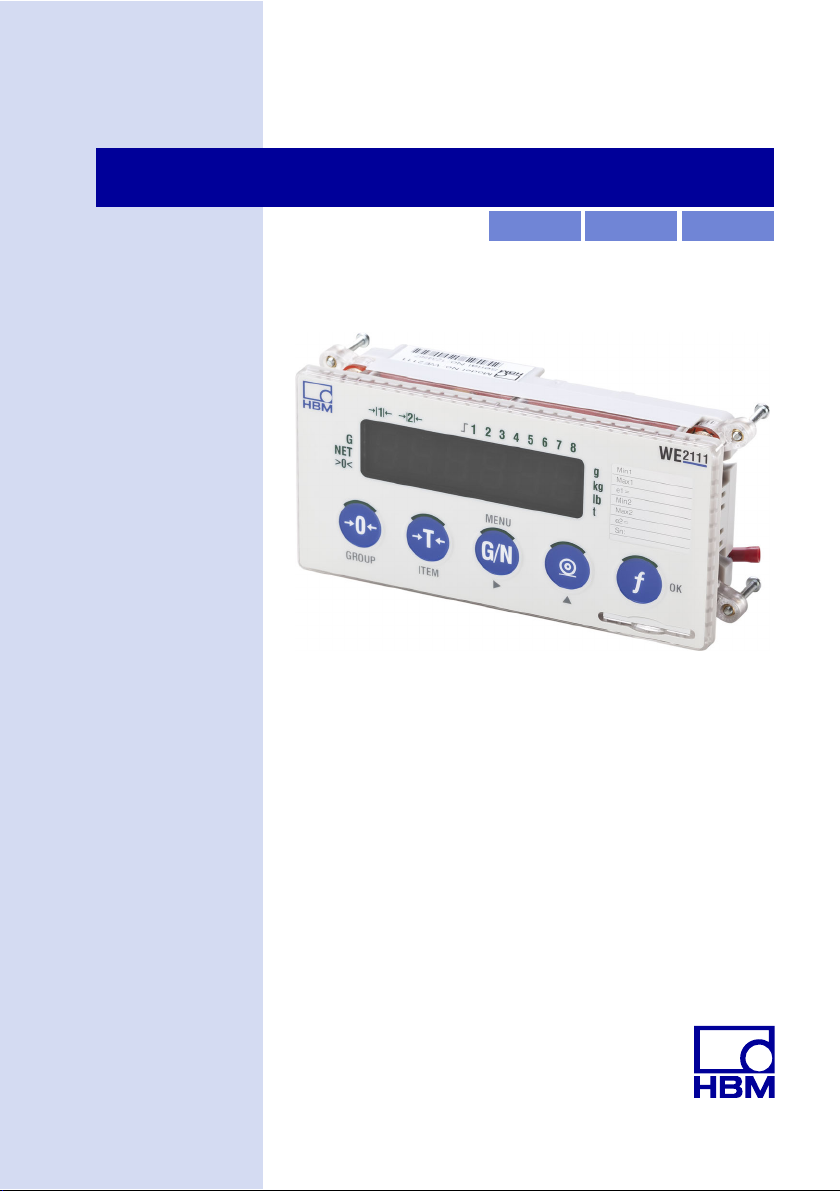
WE2111

WE2111
English
1 Safety instructions 3........................................
2 Markings used 7............................................
2.1 Symbols on the device 7......................................
2.2 The markings used in this document 7..........................
3 Introduction 9..............................................
3.1 Scope of delivery 9..........................................
3.2 Application 9................................................
3.3 Operating manual 10..........................................
4 Calibration labels and sealing 11.............................
5 Mounting optional modules 12...............................
5.1 WE2111-ZCC contact assignment 15............................
5.2 WE2111-ZS contact assignment 15.............................
6 Connecting load cells 16.....................................
7 Connecting the power supply 19..............................
7.1 Connection of DC voltage 19...................................
7.2 Connection for AC voltage 20..................................
8 Connecting the interfaces 22.................................
8.1 Serial interfaces 22...........................................
8.2 Ethernet interface 24..........................................
8.3 USB interface 25.............................................
9 Mechanical installation 26....................................
10 Start-up (quick start guide) 28................................
10.1 Switching on 28..............................................
10.2 Calling the setting menu 29....................................
2 A3983-1.0 en/de/fr

WE2111
10.3 Implementing general settings (decimal places, nominal (rated)
range, unit) 29................................................
10.4 Calibration 31................................................
11 Selling on, waste disposal and environmental protection 33....
A3983-1.0 en/de/fr 3

1 Safety instructions
Proper use
The device is to be used exclusively as a component for
a scale and directly related control tasks within the
application limits detailed in the specifications. Use for
any purpose other than the above is deemed to be
non-designated use.
Everyone involved with siting, starting up, or operating
the device must have read and understood the operating
manual and in particular the technical safety instructions.
In the interests of safety, the device should only be
operated by qualified personnel and as described in the
Operating Manual. It is also essential to comply with the
legal and safety requirements for the application
concerned during use. The same applies to the use of
accessories.
The device is not intended for use as a safety
component. Please also refer to the section: "Additional
safety precautions". Proper and safe operation requires
proper transportation, correct storage, siting and
mounting, and careful operation.
WE2111
Operating conditions
S Protect the device from direct contact with water.
S Protect the device from moisture and weather such as
rain or snow. The device degree of protection is IP20
(DIN EN 60529), the front plate degree of protection
is IP66.
S Do not expose the device to direct sunlight.
S Protect the device against impact/shock loads and
strong vibrations.
4 A3983-1.0 en/de/fr

WE2111
S Comply with the maximum permissible ambient
temperatures and maximum humidity figures stated in
the specifications.
S The device must not be modified from the design or
safety engineering point of view except with our
express agreement. In particular, any repair or
soldering work on motherboards (replacement of
components) is prohibited. When exchanging
complete modules, use only original parts from HBM.
S The device is delivered from the factory with a fixed
hardware and software configuration. Changes can
only be made within the possibilities documented in
the manuals.
S The device is intended for use in industrial
environments and corresponds to Class A in
compliance with DIN EN55011.
S The device is maintenance-free.
S Please note the following points when cleaning the
housing:
- Disconnect the device from all current and voltage
supplies before cleaning it.
- Clean the housing with a soft, slightly damp (not
wet!) cloth. You should never use solvents, since
these could damage the labeling or the housing.
- When cleaning, ensure that no liquid gets into the
device or connections.
S In accordance with national and local environmental
protection and material recovery and recycling
regulations, old equipment that can no longer be used
must be disposed of separately and not with normal
household garbage, see Chapter 11, Page 34.
A3983-1.0 en/de/fr 5

WE2111
Qualified personnel
Qualified persons means persons entrusted with the
installation, fitting, commissioning and operation of the
product who possess the appropriate qualifications for
their function.
This includes people who meet at least one of the
following three requirements:
S Knowledge of the safety concepts of measurement
and automation technology is a requirement and as
project personnel, you must be familiar with these
concepts.
S As measurement or automation plant operating
personnel, you have been instructed how to handle
the machinery. You are familiar with the operation of
the equipment and technologies described in this
documentation.
S As commissioning engineers or service engineers,
you have successfully completed the training to
qualify you to repair the automation systems. They
are also authorized to activate, ground and label
circuits and equipment in accordance with safety
engineering standards.
Working safely
S The device must not be directly connected to the
power supply system. The supply voltage must be
between 12 and 24VDC. A supply with 110 to 240V
AC
is possible with the option 1-WE2111-AC.
S Error messages should only be acknowledged once
the cause of the error is removed and no further
danger exists.
S Automation equipment and devices must be designed
in such a way that adequate protection or locking
6 A3983-1.0 en/de/fr

WE2111
against unintentional actuation is provided (e.g.
access checks, password protection, etc.).
S Additional safety precautions must be taken in terms
of both hardware and software for devices working in
networks, so that a line break or other interruptions to
signal transmission do not cause undefined states or
loss of data in the automation device.
S After making settings and carrying out activities that
are password-protected, ensure that any controls that
may be connected remain in a safe condition until the
switching performance of the device has been tested.
Additional safety precautions
Additional safety precautions that meet the requirements
of the applicable national and local accident prevention
regulations must be taken in plants where malfunctions
could cause major damage, loss of data or even personal
injury.
The scope of supply and performance of the device
covers only a small area of measurement technology.
Before starting up the device in a system, a project
planning and risk analysis must first be implemented,
taking into account all the safety aspects of
measurement and automation technology so that residual
dangers are minimized. This particularly concerns
personal and machine protection. In the event of a fault,
appropriate precautions must establish safe operating
conditions.
General dangers of failing to follow the safety
instructions
The device is state of the art and as such is failsafe. The
device may give rise to residual dangers if it is
inappropriately installed and operated.
A3983-1.0 en/de/fr 7
2 Markings used
2.1 Symbols on the device
FCC certification
This mark enables the manufacturer to guarantee that
the product complies with the requirements of the FCC
(Federal Communications Commission, USA).
CE certification
The CE mark enables the manufacturer to guarantee that
the product complies with the requirements of the
relevant EC directives (the Declaration of Conformity can
be found on the HBM website (www.hbm.com) under
HBMdoc).
Statutory waste disposal mark
In accordance with national and local environmental
protection and material recovery and recycling
regulations, old devices that can no longer be used must
be disposed of separately and not with normal household
garbage. Also see Section 11 on Page 34.
WE2111
2.2 The markings used in this document
Important instructions for your safety are specifically
identified. It is essential to follow these instructions in
order to prevent accidents and damage to property.
8 A3983-1.0 en/de/fr
WE2111
Symbol Significance
Note
Important
This marking draws your attention to a situation in
which failure to comply with safety requirements
could lead to damage to property.
This marking draws your attention to important
information about the product or about handling the
product.
This marking indicates application tips or other
information that is useful to you.
Tip
Emphasis
See …
Device -> New Bold text indicates menu items, as well as dialog and
Sampling rate Bold text in italics indicates inputs and input fields in
Italics are used to emphasize and highlight text and
identify references to sections, diagrams, or external
documents and files.
window titles in the user interfaces. Arrows between
menu items indicate the sequence in which the
menus and sub-menus are called up
the user interfaces.
A3983-1.0 en/de/fr 9

3 Introduction
3.1 Scope of delivery
S Safety instructions
S WE2111 (basic device)
S USB storage device with Quick Start Guide and
The Operating Manual and the quick start guide are
available in PDF format on the HBM website
(www.hbm.com) under HBMdoc in the section Digital
weighing electronics.
3.2 Application
The WE2111 digital weighing indicator, in combination
with SG1 load cells, enables high-precision weight
measurements. In the legal for trade sector, you can set
up scales with up to 10,000 division resolution and
multi-range/multi-interval scales with up to two times
3,000 division resolution are also possible. It is possible
to connect up to 16 load cells in larger systems, use
linearization over up to 5 intermediate points and use
various filters.
WE2111
Operating Manual as PDF
The WE2111 digital transducer electronics standard
configuration includes Ethernet, USB and RS-422/485
interfaces.
The PC software WE2111 Viewer is available for simple
parameter setting. You can download the (free) software
via the HBM website in the Digital weighing electronics
area: www.hbm.com/HBM Software.
1)
Strain gages
10 A3983-1.0 en/de/fr

WE2111
Optional components
There are several optional modules and components
available for diverse application cases. However, only
certain combinations can be connected, depending on
the module.
S Power pack module 1-WE2111-AC for connection to a
power supply with 110 to 240VAC, 50 to 60Hz.
S Plug-in module 1-WE2111-ZS with 8 freely
configurable digital inputs and/or outputs.
S Plug-in module 1-WE2111-ZCC with 2 freely
configurable digital inputs and/or outputs, analog
current output (4 … 20mA) and analog voltage output
(0 … 10V).
S Plug-in module 1-WE2111-R2 with galvanically
isolated RS-232 interface.
S Plug-in module 1-WE2111-R4 with galvanically
isolated RS-485 interface.
S Table stand 1-WE2111-ZT or housing made of
stainless steel 1-WE2111-ZH.
3.3 Operating manual
This quick start guide covers the load cell connection,
power supply and the optional modules on the WE2111,
as well as an example for setting up a scale.
Further information is provided in the WE2111 Operating
Manual.
A3983-1.0 en/de/fr 11
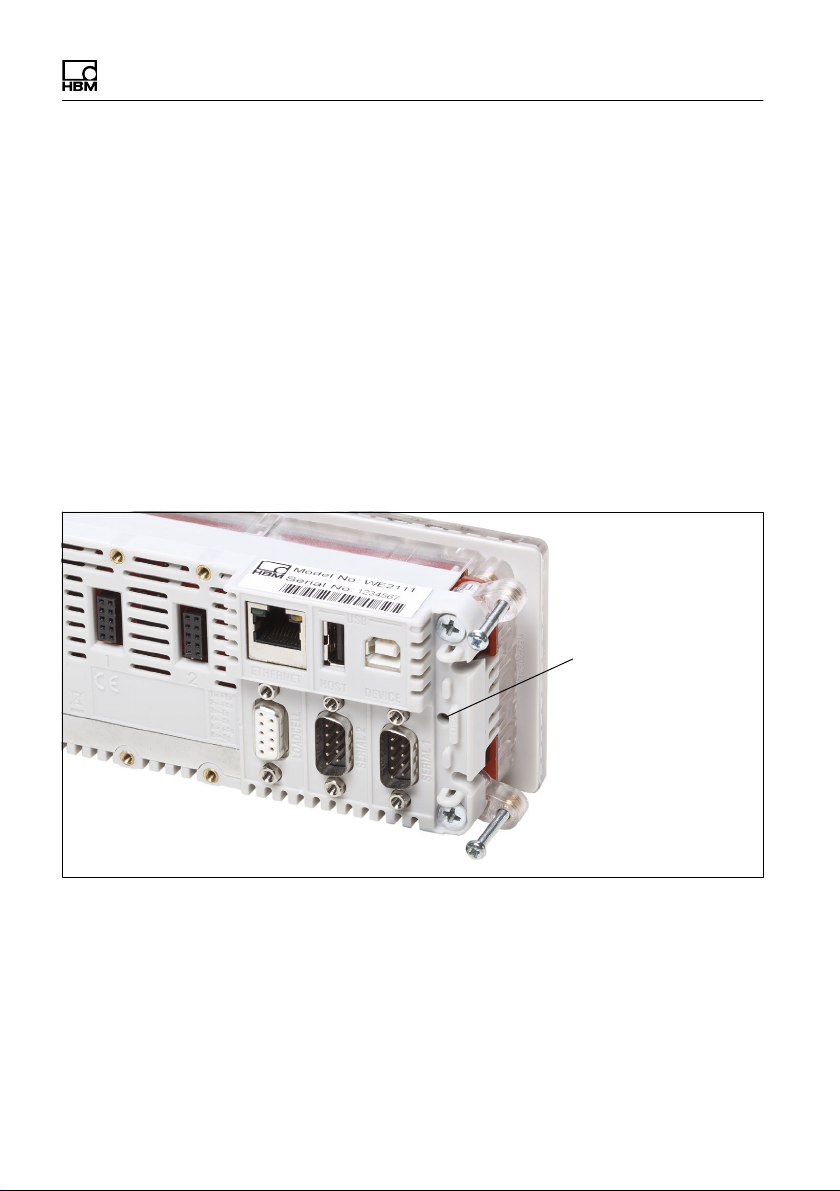
4 Calibration labels and sealing
The WE2111 calibration is implemented digitally. The
results are saved power failsafe.
Settings that change the calibration are only possible in
the setup mode "Full" (password protection
recommended). This also changes the status of the
calibration counter and can therefore be subsequently
recognized. In addition, it is possible to restrict the
access to the Full setup mode so that access is only
possible after the button on the rear is pressed (Fig. 4.1).
The button is covered by a panel and can be protected
by a suitable label, lead seal or seal.
WE2111
Hidden button
(cover removed)
Fig. 4.1 View from rear, fastener brackets swivelled out
12 A3983-1.0 en/de/fr
WE2111
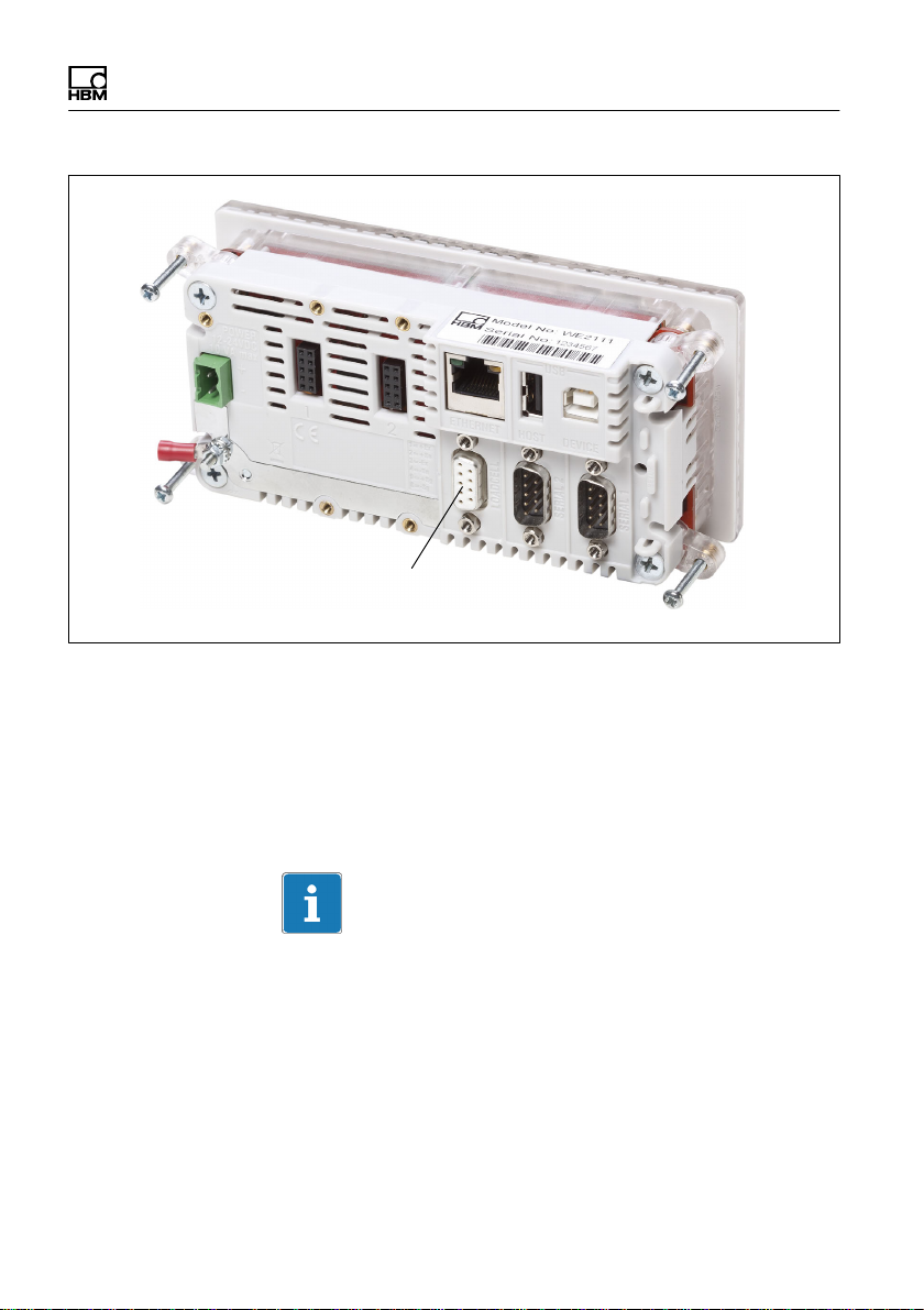
5 Mounting optional modules
Note
A module must not be connected or removed if power is
present, otherwise the WE2111 may be destroyed.
Disconnect or switch off the voltage supply before
installation/removal.
This section describes the connection of the modules for
analog or digital inputs/outputs and the interface
modules.
The connection of the power pack module is described in
Section 7.2 on Page 21.
Important
You can only connect one of the modules WE2111-ZS or
WE2111-ZCC and only one of the modules WE2111-R2
or WE2111-R4.
A total of two modules (with power pack module) can be
connected.
A3983-1.0 en/de/fr 13
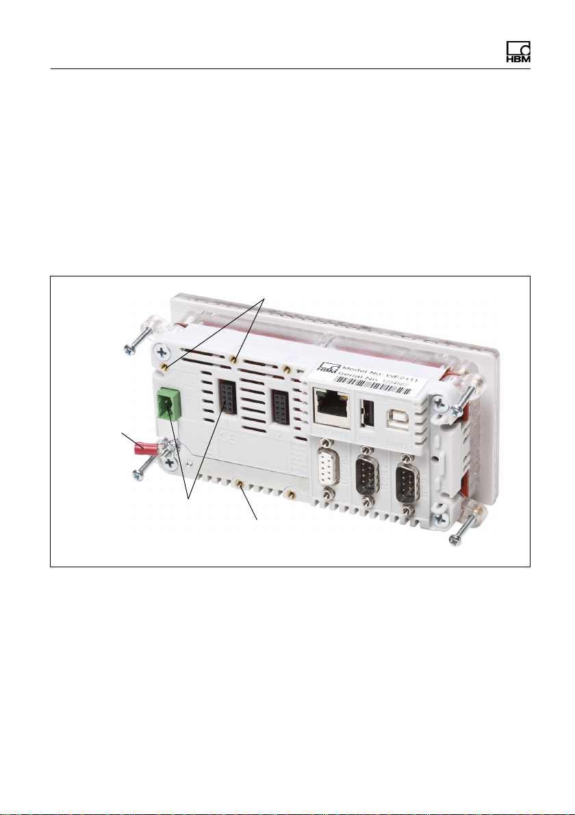
Connection sockets
Fig. 5.1 View from rear, connection of optional modules
"
WE2111
Mounting
Mounting
Plug in the module so that the connector in the
module slides into the connector socket of the
WE2111 (Fig. 5.1). If the power pack module needs to
be mounted, you must use the right-hand connector
socket. Otherwise, either connector socket can be
used for the optional modules.
14 A3983-1.0 en/de/fr
WE2111
Fastening screws
Fig. 5.2 View from rear, connection of optional modules
"
Hand-tighten the two fastening screws for the module
(Fig. 5.2).
The module is then ready for operation.
Depending on the module type, settings may need to be
implemented, e.g. which input/output should be used and
how. Further information can be found in the Operating
Manual.
Use shielded cables for the analog outputs. The cables
for the digital inputs/outputs only need to be shielded if
the cable length exceeds 30 m.
A3983-1.0 en/de/fr 15
WE2111
5.1 WE2111-ZCC contact assignment
Function Imprint
Current output (+), 600Ω max. IOUT+
Current output (-), 600Ω max. IOUT-
Voltage output (+), 2000Ω min. VOUT+
Voltage output (-), 2000Ω min. VOUTInput/output 1 I/O1
Input/output 2 I/O2
Common supply +U
Common supply -Ub (ground) COMCable shield SHIELD
b
COM+
5.2 WE2111-ZS contact assignment
Function Imprint
Common supply +U
Common supply -Ub (ground) COMInput/output 1 I/O1
Input/output 2 I/O2
Input/output 3 I/O3
Input/output 4 I/O4
Input/output 5 I/O5
Input/output 6 I/O6
Input/output 7 I/O7
Input/output 8 I/O8
Cable shield SHIELD
b
COM+
16 A3983-1.0 en/de/fr
WE2111
6 Connecting load cells
This section describes how to connect one or more load
cells.
You can connect a maximum of 16 SG load cells in a full
bridge circuit with a bridge resistance of 350Ω each.
Transducer excitation is implemented in the basic device
WE2111 with 5V
We recommend connecting the load cells via a suitable
junction if several load cells are connected, e.g. the HBM
model VKK2-8.
Important
Not all load cells can be connected in parallel. Refer to
the operating manual of the load cells to see if this is
possible.
For EMC reasons, a double shielded cable is
advantageous for connecting the load cell(s), e.g. HBM
model 4-3301.0071 with 3 ∗ 2 ∗ 0.14 m2.
(bridge excitation voltage).
DC
Contact assignment
Connector socket Function Contact No.
(Pin/Imprint)
Excitation voltage (+) 1 (+ Ex) BU (blue)
1
6
9
5
A3983-1.0 en/de/fr 17
Excitation voltage (-) 3 (- Ex) BK (black)
Sense lead (+) 2 (+ Sn) GN (green)
Sense lead (-) 4 (- Sn) GY (gray)
Measurement signal (+) 9 (+ Sg) WH (white)
Measurement signal (-) 8 (- Sg) RD (red)
HBM color code
Connector socket for load cell(s)
Fig. 6.1 View from rear, connection of load cell(s)
"
Connect a 9-pin D-Sub connector as shown in the
table with the connections of the load cell(s).
WE2111
Use shielded cables for the connecting cables and
connect the shield extensively to the connector
housing.
Important
If the load cell(s) are in four-wire configuration, the sense
leads must be connected to the excitation voltage with
jumpers: 2 (+) to 1 (+) and 4 (-) to 3 (-).
The sense lead inputs must not remain open otherwise
only error messages will be displayed (E00040, E00080
or E000C0).
18 A3983-1.0 en/de/fr

WE2111
Insert the six-wire connection up to the junction box if
you are using several transducers.
"
Plug the connector in the connector socket for the
load cell(s) (Fig. 6.1).
"
Hand-tighten the fastening screws of the connector.
The load cell(s) are now connected.
A3983-1.0 en/de/fr 19

7 Connecting the power supply
The WE2111 must be supplied with a controlled DC
voltage between 12 and 24V. The power pack module
WE2111-AC, which can supply 110 to 240V, is also
available as an option.
7.1 Connection of DC voltage
"
Connect the supply voltage to the connection marked
in Fig. 7.1.
Connection for 12
to 24VDC supply
WE2111
+
-
Grounding plug
Fig. 7.1 Connection of the power supply and grounding plug
The upper connection is connected with Plus, the
lower with Minus. The pin assignment is also
embossed on the housing.
20 A3983-1.0 en/de/fr
WE2111
Grounding plug
"
Connect the grounding plug (Fig. 7.1) with a
grounding point in the vicinity.
The resistance between grounding point and WE2111
must not exceed 2ohm.
The WE2111 is now ready for switch on.
7.2 Connection for AC voltage
Mounting
Connector sockets
Mounting
Fig. 7.2 View from rear, connection of power pack module
"
Connect the grounding plug (Fig. 7.2) with a
grounding point in the vicinity.
The resistance between grounding point and WE2111
must not exceed 2ohm.
A3983-1.0 en/de/fr 21
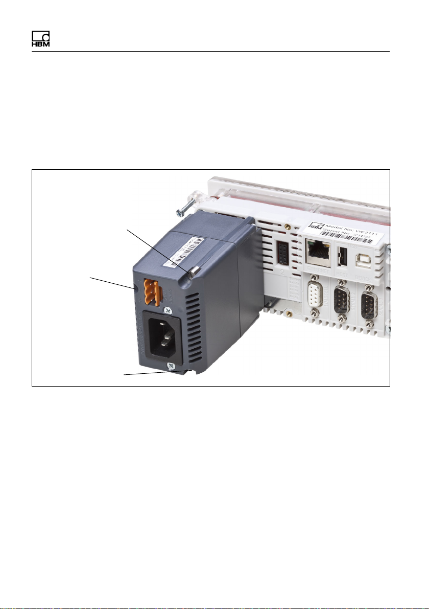
Fastening screw (1)
Fastening screw (1)
(recessed)
"
Plug in the power pack module so that the connector
in the module slides into the connector socket of the
WE2111 (Fig. 7.2).
The socket for the mains connector must be at the
bottom of the module after mounting and the output
for the 12V auxiliary voltage at the top (Fig. 7.3).
WE2111
Fastening screw (1)
(recessed)
Fig. 7.3 View from rear, mounted power pack module
"
Hand-tighten the three fastening screws (1) for the
module (Fig. 7.3).
The WE2111 is now ready for switch on.
22 A3983-1.0 en/de/fr

WE2111
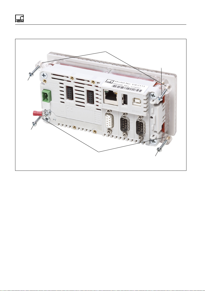
8 Connecting the interfaces
This section describes the pin assignments of the
interface sockets.
8.1 Serial interfaces
Note
There is a danger with long cable lengths (over 30 m)
that the bus nodes have different ground potentials. If
necessary, establish potential equalization between the
bus nodes with a separate cable.
Use a flexible cable with a cross-section of at least
10mm2 for the potential equalization.
All connections for the serial interfaces are available at
Serial 1. Serial 2 is set up for a connection of a serial
printer, the connections of both sockets are connected
internally.
A3983-1.0 en/de/fr 23
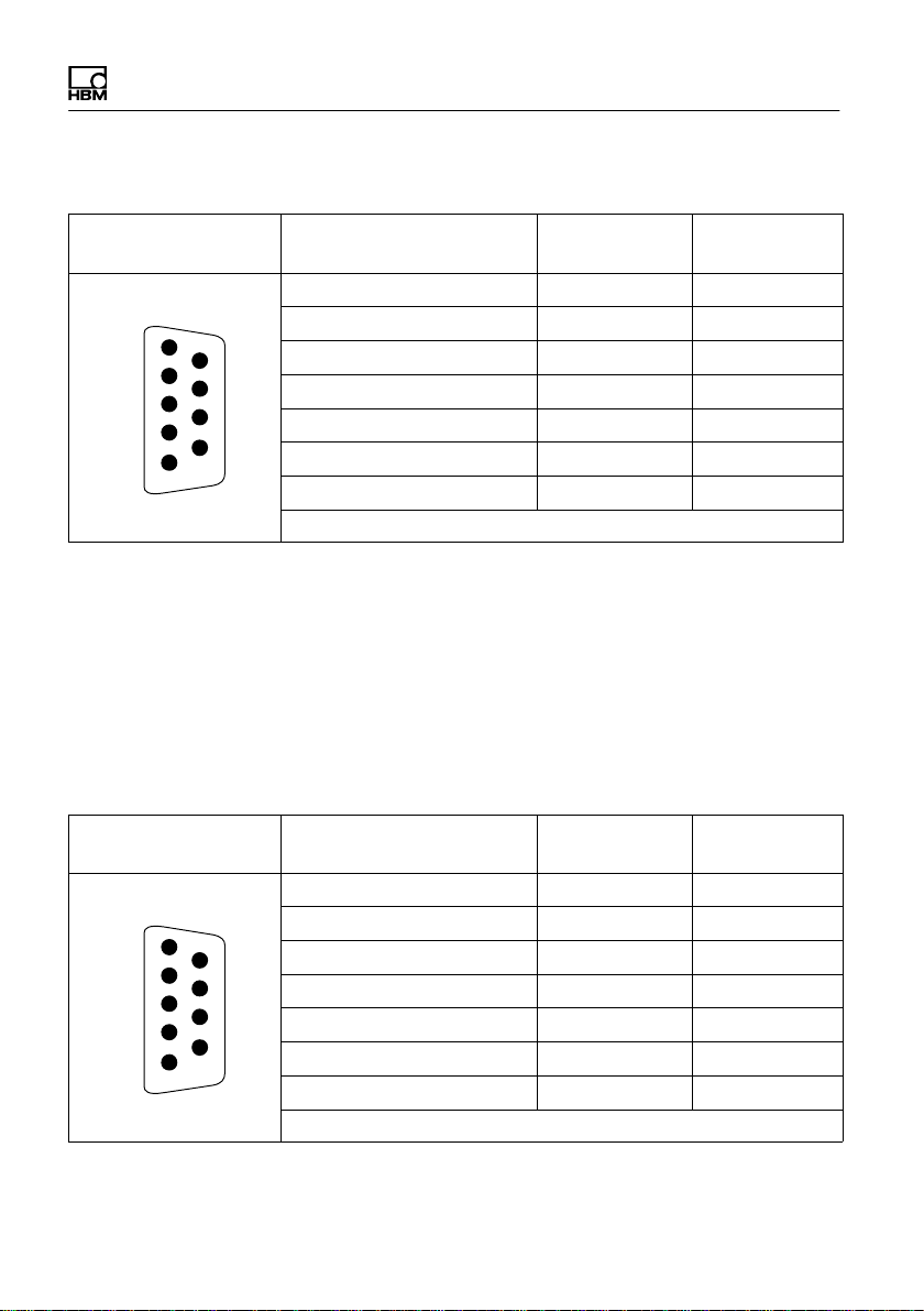
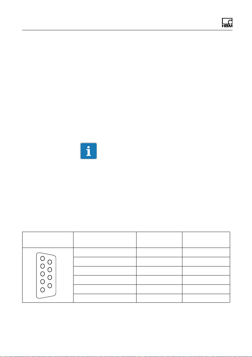
Contact assignment Serial 1
WE2111
Connector socket Function Contact No.
(Pin)
RS-232 Receive 2 RX1
RS-232 Transmit 3 TX1
5
9
6
1
RS-232 Ground 5 GND1
RS-422/485 Receive A (-) 6 RA
RS-422/485 Receive B (+) 7 RB
RS-422/485 Transmit A (-) 8 TA
RS-422/485 Transmit B (+) 9 TB
Cable shield: Attach to connector housing
If the RS-422/485 interface is not used, the inputs must
not be used. These contacts are connected through to
the second serial interface Serial 2.
The termination resistors required for the RS422/485
interface are integrated in the WE2111 and are activated
via software.
Contact assignment Serial 2
Connector socket Function Contact No.
(Pin)
RS-232 Transmit 3 TX2
RS-232 DTR Handshake 4 DTR
5
9
6
1
RS-232 Ground 5 GND2
RS-422/485 Receive A (-) 6 RA
RS-422/485 Receive B (+) 7 RB
RS-422/485 Transmit A (-) 8 TA
RS-422/485 Transmit B (+) 9 TB
Cable shield: Attach to connector housing
Abbreviation
Abbreviation
24 A3983-1.0 en/de/fr

WE2111
If the RS-422/485 interface is not used, the inputs must
not be used. These contacts are connected through to
the first serial interface Serial 1.
The termination resistors required for the RS422/485
interface are integrated in the WE2111 and are activated
via software.
8.2 Ethernet interface
The Ethernet interface enables the connection of an
Ethernet network with 10Base‐T/100Base‐TX via an
RJ45 connector.
You can assign a permanent IP address or use DHCP for
communication. The interface uses two TCP sockets for
the following purposes:
1. SER5 (Port 2222)
This interface is used by the WE2111 Viewer software
and enables bidirectional transmission of data and
commands.
2. SER6 (Port 2223)
This interface only outputs data and is used for
automatic transmission of outputs.
The ports used can be set.
A3983-1.0 en/de/fr 25

8.3 USB interface
The WE2111 has two USB interfaces:
1. USB socket, type A (slave)
This interface is for the connection of peripheral
devices such as a keyboard, USB memory stick or
USB printer.
2. USB socket, type B (host)
This interface is for the connection of a PC. You must
install a driver for operation on the PC (WE21-511) in
order to enable communication with the WE2111 as if
it were a serial interface (SER0 in the WE2111).
WE2111
26 A3983-1.0 en/de/fr

WE2111
9 Mechanical installation
Conditions on site
S Protect the device from direct contact with water.
S Protect the device from moisture and weather such as
rain or snow. The device degree of protection is IP20
(DIN EN 60529), the front plate degree of protection
is IP66.
S Do not expose the device to direct sunlight.
S Protect the device against impact/shock loads and
strong vibrations.
S Comply with the maximum permissible ambient
temperatures and maximum humidity figures stated in
the specifications.
Installation orientation
The device can be mounted in any position.
Installation
The WE2111 can either be used as a desktop device,
e.g. with the option 1-WE2111-ZT (table stand), or as a
built-in device. Mounting is identical in both cases, the
housing fits in any standard device recess as per DIN
43700 (138mm x 67mm).
"
Push the housing through the recess.
"
Swivel the four fastener brackets (1) on the corners
out by 90° to 180°, depending on the desired or
necessary fastening position (Fig. 9.1).
"
Hand-tighten the screws (2) (Fig. 9.1).
A3983-1.0 en/de/fr 27
Screw (2)
Screw (2)
WE2111
Fastener brackets (1)
Screw (2)
Fastener brackets (1)
Screw (2)
Fig. 9.1 View from rear, fastener brackets swivelled out
28 A3983-1.0 en/de/fr

WE2111
10 Start-up (quick start guide)
This section describes how to switch on the device and
what needs to be set in order to carry out weighing. The
example is based on a single-range balance for not legal
for trade operation without a password. A load cell with
10kg maximum capacity (1,000 divisions) is connected,
a 10kg weight is provided. Further information about the
various balance types and set up can be found in the
Operating Manual.
This section assumes that all necessary connections
have been made (load cell(s), power supply, etc.).
The buttons on the front panel are indicated here as
graphics with the button label, e.g.
G/N (MENU).
10.1 Switching on
for the button
"
Switch on the WE2111 power supply.
The WE2111 runs through various self-tests after
being switched on. The display initially shows bOOt,
then all segments of the display and all light displays
are activated, e.g. including the limit values and units.
The display then tests all digits from 0 to 9, i.e., the
display runs through all digits from 000000 to 999999.
Finally, the firmware version (e.g. P60c) and the
calibration counter (e.g. C00008) are displayed before
the actual measured value appears.
A3983-1.0 en/de/fr 29

10.2 Calling the setting menu
"
Press the button for several seconds.
SAFE is displayed.
"
Press the button again (briefly).
FULL is displayed.
"
Press the button.
The following are displayed in sequence: SEtUP,
firmware version (e.g. P60c), calibration counter
(e.g. C00008) and buiLd.
10.3 Implementing general settings
(decimal places, nominal (rated)
range, unit)
The display must show buiLd before the following
settings can be made.
"
Press the button twice.
WE2111
dP is displayed.
"
Press the button.
000000 is displayed.
"
Press the button until 0000.00 is displayed.
The number of decimal places is then set to two
places.
"
Press the button.
dP is displayed (decimal point).
30 A3983-1.0 en/de/fr
 Loading...