

Page 1
B 20. U9B.40 en
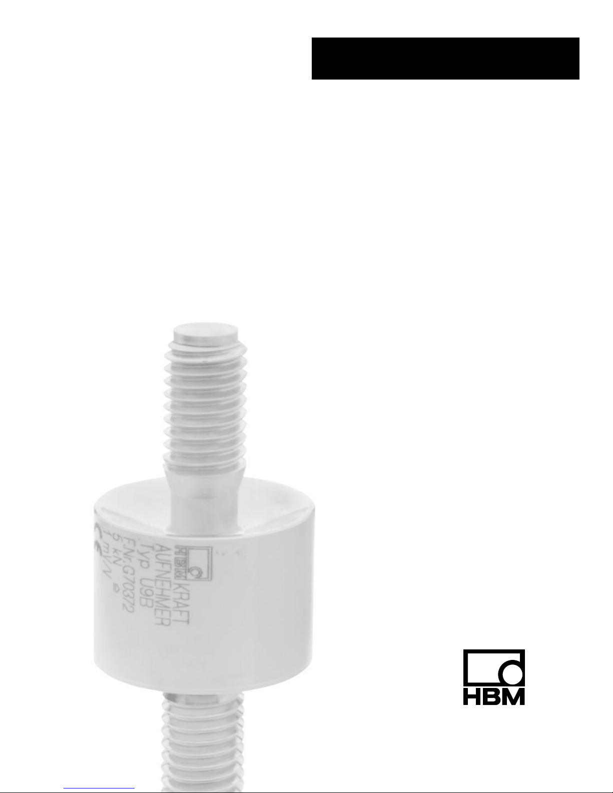
Force transducer with
strain gauge measuring
system
U9B
Operating manual
SUNSTAR传感与控制 http://www.sensor-ic.com/ TEL:0755-83376549 FAX:0755-83376182 E-MAIL:szss20@163.com
SUNSTAR自动化 http://www.sensor-ic.com/ TEL: 0755-83376489 FAX:0755-83376182 E-MAIL:szss20@163.com
Page 2

SUNSTAR传感与控制 http://www.sensor-ic.com/ TEL:0755-83376549 FAX:0755-83376182 E-MAIL:szss20@163.com
SUNSTAR自动化 http://www.sensor-ic.com/ TEL: 0755-83376489 FAX:0755-83376182 E-MAIL:szss20@163.com
Page 3

3
U9B
B 20.U9B.40 en HBM
Contents Page
Safety instructions 4 . . . . . . . . . . . . . . . . . . . . . . . . . . . . . . . . . . . . . . . . . . . . . .
1 Scope of delivery 7 . . . . . . . . . . . . . . . . . . . . . . . . . . . . . . . . . . . . . . . . .
2 Field of application and notes on use 7 . . . . . . . . . . . . . . . . . . . . . . .
3 Structure and mode of operation 8 . . . . . . . . . . . . . . . . . . . . . . . . . . .
3.1 Measuring element 8 . . . . . . . . . . . . . . . . . . . . . . . . . . . . . . . . . . . . . . . . .
3.2 Measuring procedure, output signal 8 . . . . . . . . . . . . . . . . . . . . . . . . . . .
4 Conditions at the site of installation 8 . . . . . . . . . . . . . . . . . . . . . . . .
4.1 Ambient temperature 8 . . . . . . . . . . . . . . . . . . . . . . . . . . . . . . . . . . . . . . .
4.2 Humidity 9 . . . . . . . . . . . . . . . . . . . . . . . . . . . . . . . . . . . . . . . . . . . . . . . . . .
4.3 Deposits 9 . . . . . . . . . . . . . . . . . . . . . . . . . . . . . . . . . . . . . . . . . . . . . . . . . .
4.4 External pressure 9 . . . . . . . . . . . . . . . . . . . . . . . . . . . . . . . . . . . . . . . . . .
5 Mechanical installation 10 . . . . . . . . . . . . . . . . . . . . . . . . . . . . . . . . . . . .
5.1 Important precautions during installation 10 . . . . . . . . . . . . . . . . . . . . . . .
5.2 General guidelines for installation 10 . . . . . . . . . . . . . . . . . . . . . . . . . . . .
5.2.1 Mounting for tensile and compressive loads 10 . . . . . . . . . . . . . . . . . . . .
6 Electrical connection 1 1 . . . . . . . . . . . . . . . . . . . . . . . . . . . . . . . . . . . . . .
6.1 Notes on wiring 11 . . . . . . . . . . . . . . . . . . . . . . . . . . . . . . . . . . . . . . . . . . . .
6.2 Allocation of the cable cores 11 . . . . . . . . . . . . . . . . . . . . . . . . . . . . . . . . .
6.3 Connection technique 12 . . . . . . . . . . . . . . . . . . . . . . . . . . . . . . . . . . . . . . .
6.4 Cable extensions 13 . . . . . . . . . . . . . . . . . . . . . . . . . . . . . . . . . . . . . . . . . . .
6.5 Parallel connection of more then one transducers 13 . . . . . . . . . . . . . . .
7 Technical data 14 . . . . . . . . . . . . . . . . . . . . . . . . . . . . . . . . . . . . . . . . . . . .
8 Dimensions (in mm) 15 . . . . . . . . . . . . . . . . . . . . . . . . . . . . . . . . . . . . . . .
9 Copy of Declaration of Conformity 16 . . . . . . . . . . . . . . . . . . . . . . . . . .
SUNSTAR传感与控制 http://www.sensor-ic.com/ TEL:0755-83376549 FAX:0755-83376182 E-MAIL:szss20@163.com
SUNSTAR自动化 http://www.sensor-ic.com/ TEL: 0755-83376489 FAX:0755-83376182 E-MAIL:szss20@163.com
Page 4

4
U9B
B 20.U9B.40 en HBM
Safety instructions
Use in accordance with the regulations
Force transducers in the U9B range are designed for measuring static and
dynamic compressive forces. Use for any additional purpose shall be deemed
to be not in accordance with the regulations.
In the interests of safety, the transducer should only be operated as described
in the Mounting Instructions. It is also essential to observe the appropriate
legal and safety regulations for the application concerned during use. The
same applies to the use of accessories.
The transducer is not a safety element within the meaning of its use as
intended. Proper and safe operation of this transducer requires proper
transportation, correct storage, assembly and mounting and careful operation
and maintenance.
General dangers due to non–observance of the safety instructions
The U9B force transducer corresponds to the state of the art and is fail–safe.
The transducers can give rise to residual dangers if they are inappropriately
installed and operated by untrained personnel.
Everyone involved with the installation, commissioning, maintenance or repair
of a force transducer must have read and understood the Mounting
Instructions and in particular the technical safety instructions.
Residual dangers
The scope of supply and performance of the transducer covers only a small
area of force measurement technique. In addition, equipment planners,
installers and operators should plan, implement and respond to the safety
engineering considerations of force measurement technique in such a way as
to minimise residual dangers. Prevailing regulations must be complied with at
all times. There must be reference to the residual dangers connected with
force measurement technique.
SUNSTAR传感与控制 http://www.sensor-ic.com/ TEL:0755-83376549 FAX:0755-83376182 E-MAIL:szss20@163.com
SUNSTAR自动化 http://www.sensor-ic.com/ TEL: 0755-83376489 FAX:0755-83376182 E-MAIL:szss20@163.com
Page 5
5
U9B
B 20.U9B.40 en HBM
In these mounting instructions residual dangers are pointed out using the
following symbols:
Symbol:
DANGER
Meaning: Highest level of danger
Warns of a directly dangerous situation in which failure to comply with safety
requirements will lead to death or serious physical injury.
Symbol:
WARNING
Meaning: Possibly dangerous situation
Warns of a potentially dangerous situation in which failure to comply with
safety requirements can lead to death or serious physical injury.
Symbol:
ATTENTION
Meaning: Possibly dangerous situation
Warns of a potentially dangerous situation in which failure to comply with
safety requirements could lead to damage to property, slight or moderate
physical injury.
Symbol:
NOTE
Refers to the fact that important information is being given about the product
or its use.
Symbol:
Meaning: CE mark
The CE mark signals a guarantee by the manufacturer that his product meets
the requirements of the relevant EC directives (see Declaration of conformity
at the end of this document).
SUNSTAR传感与控制 http://www.sensor-ic.com/ TEL:0755-83376549 FAX:0755-83376182 E-MAIL:szss20@163.com
SUNSTAR自动化 http://www.sensor-ic.com/ TEL: 0755-83376489 FAX:0755-83376182 E-MAIL:szss20@163.com
Page 6

6
U9B
B 20.U9B.40 en HBM
Prohibition of own conversions and modifications
The transducer must not be modified from the design or safety engineering
point of view except with our express agreement. Any modification shall
exclude all liability on our part for any damage resulting therefrom.
Qualified personnel
This instrument is only to be installed by qualified personnel strictly in
accordance with the technical data and with the safety rules and regulations
which follow. It is also essential to observe the appropriate legal and safety
regulations for the application concerned. The same applies to the use of
accessories.
Qualified personnel means persons entrusted with the installation, fitting,
commissioning and operation of the product who possess the appropriate
qualifications for their function.
Conditions on site
Protect the transducer from damp and weather influences such as rain, snow,
etc.
Maintenance
The U9B force transducer is maintenance free.
Accident prevention
Although the specified nominal force in the destructive range is several times
the full scale value, the relevant accident prevention regulations from the
trade associations must be taken into consideration.
SUNSTAR传感与控制 http://www.sensor-ic.com/ TEL:0755-83376549 FAX:0755-83376182 E-MAIL:szss20@163.com
SUNSTAR自动化 http://www.sensor-ic.com/ TEL: 0755-83376489 FAX:0755-83376182 E-MAIL:szss20@163.com
Page 7

7
U9B
B 20.U9B.40 en HBM
1 Scope of delivery
Force transducer U9B; mounting instruction
2 Field of application and notes on use
The transducers are intended for measuring static and dynamic tensile and
compressive forces. Their very small dimensions make them ideal for use
where little space is available (for example for measuring penetration forces in
manufacturing processes).
The force transducers are designed for harsh environmental conditions and
stringent service in requirements. They are maintenance-free and can even
be installed in places where access is difficult. Their electrical measuring signals can be transmitted to remote measuring stations and control rooms and
displayed or recorded there and used for control and regulating duties.
The transducers, as precision measuring instruments, require careful handling
during transport and installation. Loading impacts (for example ”free fall”
application of the load) even during measurement operations can lead to unexpected overloads with permanent damage.
Special care must therefore be given to the base of the housing, which is relatively thin.
The limits for permissible mechanical, thermal and electrical stressing are
given in the technical data. It is essential that these be respected.
SUNSTAR传感与控制 http://www.sensor-ic.com/ TEL:0755-83376549 FAX:0755-83376182 E-MAIL:szss20@163.com
SUNSTAR自动化 http://www.sensor-ic.com/ TEL: 0755-83376489 FAX:0755-83376182 E-MAIL:szss20@163.com
Page 8

8
U9B
B 20.U9B.40 en HBM
3 Structure and mode of operation
3.1 Measuring element
The force is transferred to the diaphragm measuring element in the U9B by a
threaded bolt. This type of measuring element has the advantage in that it
also acts as a housing, protecting the applied strain gauges. The transducer is
hermetically sealed by an adapter with threaded bolt which is welded on the
bottom.
3.2 Measuring procedure, output signal
The measuring spring and strain gauges are elastically deformed by a load
acting in the direction of measurement. The strain gauges modify their resistance proportionally to their change in length. The Wheatstone bridge is thus
detuned. When a bridge excitation voltage is applied, the circuit supplies an
output signal proportional to the change in resistance and hence also proportional to the force applied.
A measuring amplifier, suitable for strain gaugs measurements, is needed to
process the measurement signal.
4 Conditions at the site of installation
4.1 Ambient temperature
To achieve optimum measuring results, the nominal temperature range from
-10°C to +70°C must be maintained. Ideally, the temperatures should be
constant or subject to slow variations. The temperature effects indicated are
applicable – in compliance with VDI/VDE Recommendation 2637 – when the
temperatures do not change faster than 5 K/h.
SUNSTAR传感与控制 http://www.sensor-ic.com/ TEL:0755-83376549 FAX:0755-83376182 E-MAIL:szss20@163.com
SUNSTAR自动化 http://www.sensor-ic.com/ TEL: 0755-83376489 FAX:0755-83376182 E-MAIL:szss20@163.com
Page 9

9
U9B
B 20.U9B.40 en HBM
Temperature gradients in the transducer by cooling or heating on one side
(radiant heat) cause problems. A screen to protect against radiant heat and
thermal insulation on all sides produce marked improvements. Naturally, these
should not cause any force shunt.
NOTE:
The transducer output signal can be affected by the warmth of
the hand. If measurements are made at room temperature
(about 20°C), then you should wait about 15 min. after handling
the transducer before taking measurements.
4.2 Humidity
Ambient humidity and a tropical climate do not affect the function of the transducer, according to the classification of the protection indicated, corresponding to protection class IP 67 to EN 60 529.
IP 67 means protected against the ingress of dust. It is also protected against
water, if the transducer is immersed in water under specified conditions with
regard to pressure and time (0.5 h in 1 m depth of water).
The housings of the transducers are manufactured entirely in stainless steel.
They can be used in harsh environments. The sheath of the connection cable
consists of polyurethane (PUR).
4.3 Deposits
Dust, dirt and other foreign bodies should not be allowed to accumulate to the
point where they convey part of the measuring force to the housing, thus falsifying the measured value (force shunt).
4.4 External pressure
The external atmospheric pressure can lie between 0 and 5 bars. Please note
that pressure fluctuations can displace the zero point.
Nennlast kN 0.5 1 2 5 10 50
Change in zero point for a change of
10mbar in ambient pressure (related to
the nominal load)
% 0.01 0.006 0.01 0.004 0.002 0.001
SUNSTAR传感与控制 http://www.sensor-ic.com/ TEL:0755-83376549 FAX:0755-83376182 E-MAIL:szss20@163.com
SUNSTAR自动化 http://www.sensor-ic.com/ TEL: 0755-83376489 FAX:0755-83376182 E-MAIL:szss20@163.com
Page 10

10
U9B
B 20.U9B.40 en HBM
5 Mechanical installation
5.1 Important precautions during installation
• Handle the transducers carefully.
• The force application surfaces on the transducer and on the mounting
accessories must be absolutely clean and seat properly.
• Do not overload the transducer, even briefly. Also short-term overloads
– e.g. due to unevenly distributed support loads – must be avoided.
• Each transducer should be shunted by a stranded copper cable (approx.
50mm
2
) during or immediately after installation. For this purpose, HBM
supplies very flexible earthing cable EEK
5.2 General guidelines for installation
Force must act on the force transducer precisely in the direction of measurement as far as possible. Off-centre loading and side loading or lateral forces
are interference variables, and therefore causes for measuring errors, and
they can damage the transducer by exceeding the permissible limits. Side
loads and lateral forces also include the relevant components of any measurement quantities which may be introduced at an oblique angle.
5.2.1 Mounting for tensile and compressive loads
The transducer can measure axial forces in the tensile and the compressive
directions. Even alternating loads are measured properly. To achieve this
though, the transducer must be mounted without any axial play.
Tensile and/or compressive forces are transferred via the two threaded bolts.
The force transfer parts are locked against the transducer using the hexagon
nuts included with the supplied items. To do this, the transducer is loaded with
the nominal force and the nuts tightened with the relevant tightening torque:
Nominal force (kN) Tightening torque (Nm)
0.5...1 8
2...20 40
50 200
As an installation aid, HBM recommends the knuckle eyes (see Chapter 9
”Dimensions”) which prevent transfer to the transducer of torsion and bending
moments as well as lateral forces. With dynamic loading pliable tie rods
should be used.
SUNSTAR传感与控制 http://www.sensor-ic.com/ TEL:0755-83376549 FAX:0755-83376182 E-MAIL:szss20@163.com
SUNSTAR自动化 http://www.sensor-ic.com/ TEL: 0755-83376489 FAX:0755-83376182 E-MAIL:szss20@163.com
Page 11

11
U9B
B 20.U9B.40 en HBM
6 Electrical connection
6.1 Notes on wiring
Electrical and magnetic fields often cause the introduction of disturbing voltages into the measuring circuit. These disturbances are chiefly caused by
heavy current conductors installed parallel to the measuring lines, but they
can also be produced by contactors or electric motors in the vicinity. Also interference voltages can be occur along the electrical path, in particular
through earthing the measuring system at a number of points, causing differences in potential.
To avoid noise injection,please note the following:
• Use only screened, low capacitance measuring (cable from HBM fulfills
these requirements).
• Do not lay the measuring cable parallel to power and control lines. If this is
not possible (e.g. in cable ducts), the measuring cable can be protected,
e.g. by steel conduit and a minimum distance of 50cm is maintained to the
other cables.
• The stray fields of transformers, motors and contactors must be avoided.
• Do not wire the transducer, amplifier and display device to multiple earths.
All equipment in the measuring system should be connected to the same
earth conductor.
• Further information can be taken from our reprint ”Electromagnetic Com-
patibility EMC”
6.2 Allocation of the cable cores
The 1.5 m long connection lead of the transducer has colour-coded free core
ends. The cable screen (YE) should be connected to the transducer ground. If
the transducer is connected according to the information given in the table,
the output voltage from the amplifier is positive for a compression load on the
transducer. If a negative output voltage is required at the measuring amplifier
during compressive loading, cores white and red of the transducer should be
changed over at the amplifier input.
SUNSTAR传感与控制 http://www.sensor-ic.com/ TEL:0755-83376549 FAX:0755-83376182 E-MAIL:szss20@163.com
SUNSTAR自动化 http://www.sensor-ic.com/ TEL: 0755-83376489 FAX:0755-83376182 E-MAIL:szss20@163.com
Page 12

12
U9B
B 20.U9B.40 en HBM
6.3 Connection technique
The transducers are fitted with a four-core connection cable and calibrated as
standard using the four-wire circuit
wh (white) Measuring signal (+)
bk (black) Bridge excitation voltage (–)
rd (red) Measuring signal (–)
bu (blue) Bridge excitation voltage (+)
ye (yellow) Cable screen
Fig. 6.1: Transducer with four-core cable
wh (white) Measuring signal (+)
bk (black) Bridge excitation voltage (–)
rd (red) Measuring signal (–)
bu (blue) Bridge excitation voltage (+)
ye (yellow) Cable screen
Sensor circuit
Sensor circuit
Fig. 6.2: Transducer with four-core cable, amplifier in six wire technique
ATTENTION:
There are balancing resistors under a coloured heat-shrink sleeve
at the end of the cable that must not be removed (re-use when
shortening the cable).
SUNSTAR传感与控制 http://www.sensor-ic.com/ TEL:0755-83376549 FAX:0755-83376182 E-MAIL:szss20@163.com
SUNSTAR自动化 http://www.sensor-ic.com/ TEL: 0755-83376489 FAX:0755-83376182 E-MAIL:szss20@163.com
Page 13

13
U9B
B 20.U9B.40 en HBM
6.4 Cable extensions
Extension cables must be of the screened low-capacitance type (HBM cables
fulfil this requirement). For cable extensions, care must be tacken to ensure a
satisfactory connection with the lowest transfer resistance and good insulation. The plug connectors from HBM fulfil these requirements.
If special humidity protection is required, e.g. the KVM Cable Joining Sleeves
(soldered and potted joints) or the VKK cable connection box (screwed connections in cast housing) can be used.
6.5 Parallel connection of more then one transducers
The parallel wiring of a number of transducers is normally possible. This might
lead to measurement errors through due to different output resistances. When
wiring transducers in parallel, cores of the same colour are connected together.
The overall arrangement of transducers having the same nominal force – with
even load distribution – can be loaded with the sum of the individual forces.
The sensitivity of the complete circuit corresponds to the sensitivity of a single
transducer.
SUNSTAR传感与控制 http://www.sensor-ic.com/ TEL:0755-83376549 FAX:0755-83376182 E-MAIL:szss20@163.com
SUNSTAR自动化 http://www.sensor-ic.com/ TEL: 0755-83376489 FAX:0755-83376182 E-MAIL:szss20@163.com
Page 14

14
U9B
B 20.U9B.40 en HBM
7 Technical data
Type U9B
Nominal force kN 0.5 1 2 5 10 20 50
Accuracy class 0.5
Nominal sensitivity C
nom
mV/V 1
Relative sensitivity deviation d
c
% v"1 tens. / v"2 compress.
Effect of temperature per 10K on
sensitivity
in the nominal temperature range
in the service temperature range
TK
C
%
%
v "0.5
v "0.8
Effect of temperature per 10K on
zero signal
in the nominal temperature range
in the service temperature range
TK
0
%
%
v "0.5
v "0.8
Linearity % v "0.5
Hysteresis related to measuring
range limit
U %
v "0.5
Span in fixed mounting orientation % v "0.5
Creep at nominal load and refer-
ence temperature
over 30 min
d
crF+E
% v "0.2
Input resistance (BK-BU) at reference temperature
R
e
Ω u 345
Output resistance (RD-WH) at reference temperature
R
a
Ω
300–400
Insulation resistance R
Is
GΩ u 1
Service range of supply voltage B
U,G
V
0.5...12
Reference supply voltage U
ref
V 5
Reference temperature t
ref
°C [°F] +23 [+73.4]
Nominal temperature range B
t,nom
°C [°F] –10..70 [+14...+158]
Service temperature range B
t,G
°C [°F] –30...+85 [–22...+185]
Storage temperature range B
t,S
°C [°F] –30...+85 [–22...+185]
Protection class to EN 60 529 IP 67
Nominal measurement displace-
ment "15%
S
nom
mm t 0,1
Natural frequency "15% kHz 15.5 23.7 18.7 20 23 27.8 20
Service load (FG) % 120
Breaking load (FB) %
u200
Relative static side-load limit
1)
(FQ) %
40 20
Permissible vibration amplitude
to DIN 50 100
F
rb
% 70 40
Weight, approx. g 65 100 400
Cable length m 1.5
1
) referred to the load transfer point 2mm above diaphragm
SUNSTAR传感与控制 http://www.sensor-ic.com/ TEL:0755-83376549 FAX:0755-83376182 E-MAIL:szss20@163.com
SUNSTAR自动化 http://www.sensor-ic.com/ TEL: 0755-83376489 FAX:0755-83376182 E-MAIL:szss20@163.com
Page 15

15
U9B
B 20.U9B.40 en HBM
8 Dimensions (in mm)
B
EG
F
F
M
M
A
Y
R
C
Cable Ø 3
Cable length 1,5 m
a.f
R
Z
U9B; for nominal forces 2…50kN
a.f 9
Nominal force A
–0.1
B C E F G M R SW Y Z
0.5...1 kN 26 44.5 20.5 13 9.5 13.5 M5 20 8 ca.5.5 2.5
2...20 kN 26 60 28.5 21 16 21 M10 40 17 ca.5.5 5
50 kN 46 84 40 28 21.5 28 M16 x 1.5 80 24 ca.5.5 8
W
H
B
∅
A
D
G
∅J
∅K
F
L
M
AF
Knuckle eye ZGW, stainless (Accessories)
for Nominal
force
A B D F G H J K L M A.F W
0.5...1 kN 10 5
H7
18 27 36 6 9 11 4 M5 9 8
2...20 kN 20 10
H7
28 43 57 10.5 15 19 6.5 M10 17 14
50 kN 28 16
H7
42 64 85 15 22 27 8 M16x1.5 22 21
SUNSTAR传感与控制 http://www.sensor-ic.com/ TEL:0755-83376549 FAX:0755-83376182 E-MAIL:szss20@163.com
SUNSTAR自动化 http://www.sensor-ic.com/ TEL: 0755-83376489 FAX:0755-83376182 E-MAIL:szss20@163.com
Page 16

HOTTINGER
BALDWIN
MESSTECHNIK
HOTTINGER BALDWIN MESSTECHNIK GMBH
Im Tiefen See 45 – D-64293 Darmstadt
Tel. ++49/6151/803-0, Fax. ++ 49/6151/894896
16
U9B
B 20.U9B.40 en HBM
9 Copy of Declaration of Conformity
Konformitätserklärung Declaration of Conformity Déclaration de Conformité
Document: 065/05.1996
Wir, We, Nous
Hottinger Baldwin Messtechnik GmbH, Darmstadt
erklären in alleiniger Verantwortung, daß das Produkt
declare under our sole responsibility
that the product
déclarons sous notre seule responsabilité que le produit
Kraftaufnehmer der Typenreihe U9B (C9B und Sondertypen)
auf das sich diese Erklärung be-
zieht, mit der/den folgenden
Norm(en) oder normativen Dokument(en) übereinstimmt (siehe
Seite 2) gemäß den Bestimmungen
der Richtlinie(n)
to which this declaration relates is in
conformity with the following standard(s) or other normative document(s) (see page 2) following the
provisions of Directive(s)
auquel se réfère cette déclaration
est conforme à la (aux) norme(s) ou
autre(s) document(s) normatif(s)
(voir page 2) conformément aux dispositions de(s) Directive(s)
89/336/EWG – Richtlinie des Rates vom 3. Mai 1989 zur Angleichung der Rechtsvorschriften der Mitglieds-
staaten über die elektromagnetische Verträglichkeit, geändert durch 91/263/EWG, 92/31/EWG
und 93/68/EWG
Erstmalige Anbringung der CEKennzeichnung: 1995
Die Absicherung aller produktspezifischen Qualitätsmerkmale erfolgt
auf Basis eines von der DQS
(Deutsche Gesellschaft zur Zertifizierung von Qualitätsmanagementsystemen) seit 1986 zertifizierten
Qualitätsmanagementsystems
nach DIN ISO 9001
(Reg.-Nr. DQS-10001).
Die Überprüfung der sicherheitsrelevanten Merkmale (Elektromagnetische Verträglichkeit, Sicherheit
elektrischer Betriebsmittel) führt ein
von der DATech erstmal 1991 akkreditiertes Prüflaboratorium (Reg.Nr. DAT-P-006 und
DAT-P-012) unabhängig im Hause
HBM durch.
Darmstadt, 10.05.96
First attachment of the CE mark: 1995
All product-related features are secured by a quality system in accordance with DIN ISO 9001, certified by
DQS (Deutsche Gesellschaft zur Zertifizierung von Qualitätsmanagementsystemen) since 1986 (Reg.-No.
DQS-10001). The safety-relevant features (electromagnetic compatibility,
safety of electrical apparatus) are verified at HBM by an independent resting
laboratory which has been accredited
by DATech in 1991 for the first time
(Reg Nos. DAT-P-006 and
DAT-P-012).
Première application de la marque
CE: 1995
Chez HBM, la détermination de tous
les critères de qualité relatifs à un
produit spécifique est faire sur la
base d‘un protocole DQS (Deutsche
Gesellschaft zur Zertifizierung von
Qualitätsmanagementsystemem)
certifiant, depuis 1986, notre
système d‘assurance qualité selon
DIN ISO 9001
(Reg.-No. DQS-10001).
De même, tous les critères de
protection électrique et de compatibilité électromagnetique sont certifiès par un laboratoire d‘essais indé-
pendant et accrèdiré depuis 1991
(Reg.-No. DAT-P-006 et
DAT-P-012.)
SUNSTAR传感与控制 http://www.sensor-ic.com/ TEL:0755-83376549 FAX:0755-83376182 E-MAIL:szss20@163.com
SUNSTAR自动化 http://www.sensor-ic.com/ TEL: 0755-83376489 FAX:0755-83376182 E-MAIL:szss20@163.com
Page 17

17
U9B
B 20.U9B.40 en HBM
Seite 2 zu Page 2 of Page 2 du
Document: 065/05.1996
Diese Erklärung bescheinigt die
Übereinstimmung mit den genann-
ten Richtlinien, beinhaltet jedoch
keine Zusicherung von Eigenschaften.
Die Sicherheitshinweise der mitgelieferte Produktdokumentation sind
zu beachten.
Folgende Normen werden zum
Nachweis der Übereinstimmung mit
den Vorschriften der Richtlinie(n)
eingehalten.
This declaration certifies conformity
which the Directives listed above, but
is no asservation of characteristics.
Safety directions of the delivered
product documentation have to be followed.
The following standards are fulfilled as
proof of conformity with the provisions
of the Directive(s)
Cette déclaration atteste al conformité avec les directives citées mais
n‘assure pas un certain charaktère.
S.v.p. observez les indications de
sécurité de la documentation du
produit ajoutée.
Pour la demonstration de la conformité aux disposition de(s) Directive(s) le produit satisfait les
normes:
EN 50082-2: 1995 Elektromagnetische Verträglichkeit (EMV); Fachgrundnorm Störfestigkeit; Teil 2:
Industriebereich; Deutsche Fassung
SUNSTAR传感与控制 http://www.sensor-ic.com/ TEL:0755-83376549 FAX:0755-83376182 E-MAIL:szss20@163.com
SUNSTAR自动化 http://www.sensor-ic.com/ TEL: 0755-83376489 FAX:0755-83376182 E-MAIL:szss20@163.com
Page 18

18
U9B
B 20.U9B.40 en HBM
SUNSTAR传感与控制 http://www.sensor-ic.com/ TEL:0755-83376549 FAX:0755-83376182 E-MAIL:szss20@163.com
SUNSTAR自动化 http://www.sensor-ic.com/ TEL: 0755-83376489 FAX:0755-83376182 E-MAIL:szss20@163.com
Page 19

19
U9B
B 20.U9B.40 en HBM
SUNSTAR传感与控制 http://www.sensor-ic.com/ TEL:0755-83376549 FAX:0755-83376182 E-MAIL:szss20@163.com
SUNSTAR自动化 http://www.sensor-ic.com/ TEL: 0755-83376489 FAX:0755-83376182 E-MAIL:szss20@163.com
Page 20

Hottinger Baldwin Messtechnik GmbH
Postfach 10 01 51, D-64201 Darmstadt
Im Tiefen See 45, D-64293 Darmstadt
Tel.: +49/61 51/ 8 03-0; Fax: +49/61 51/ 8039100
E–mail: support@hbm.com www.hbm.com
Modifications reserved.
All details describe our products in general form only.They are
not to be understood as express warranty and do not constitute
any liability whatsoever.
B 20. U9B.40 en
SUNSTAR传感与控制 http://www.sensor-ic.com/ TEL:0755-83376549 FAX:0755-83376182 E-MAIL:szss20@163.com
SUNSTAR自动化 http://www.sensor-ic.com/ TEL: 0755-83376489 FAX:0755-83376182 E-MAIL:szss20@163.com
 Loading...