

Page 1
Mounting Instructions | Montageanleitung
English Deutsch
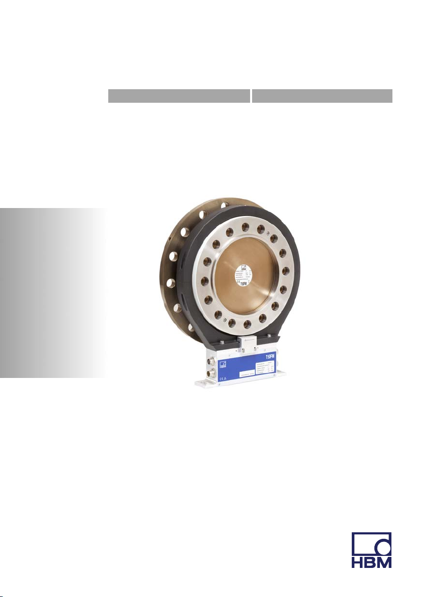
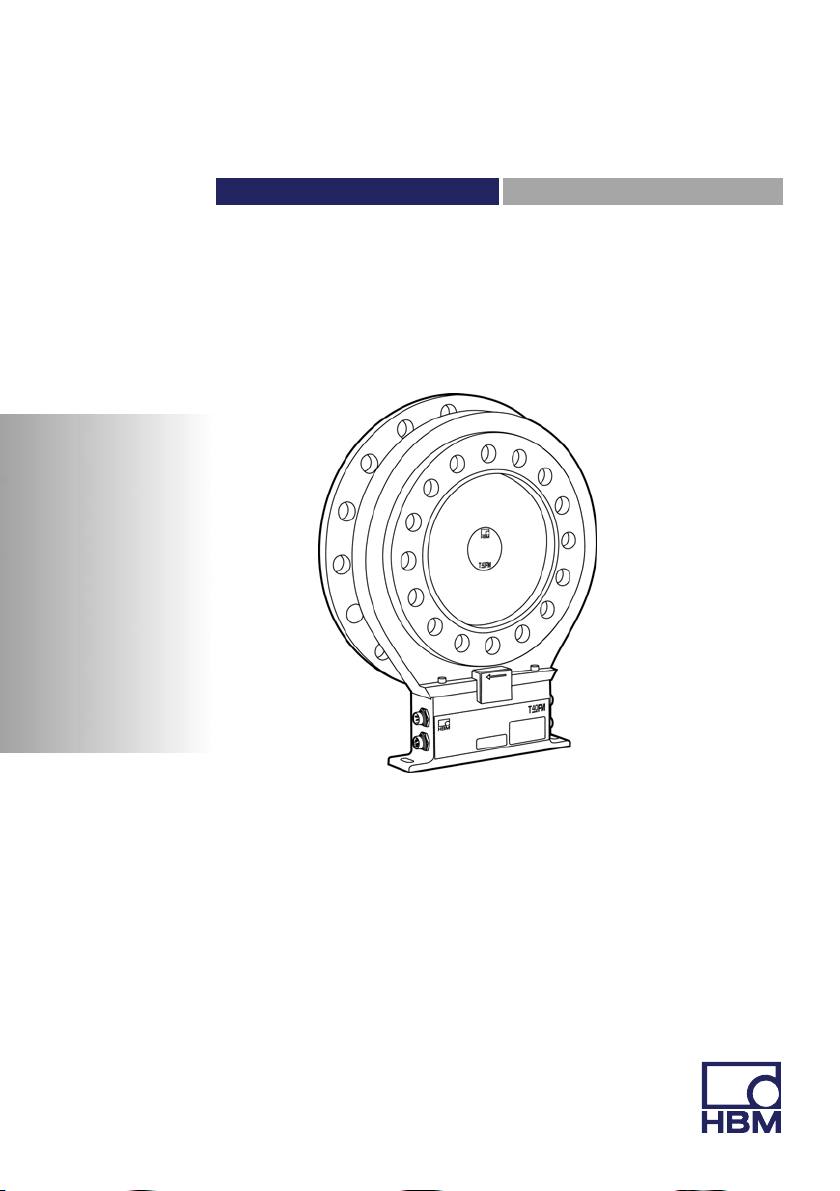
T40FM
Page 2

Hottinger Baldwin Messtechnik GmbH
Im Tiefen See 45
D-64239 Darmstadt
Tel. +49 6151 803-0
Fax +49 6151 803-9100
info@hbm.com
www.hbm.com
Mat.: 7-2001.3276
DVS: A3276-11.0 HBM: public
09.2017
E Hottinger Baldwin Messtechnik GmbH.
Subject to modifications.
All product descriptions are for general information only.
They are not to be understood as a guarantee of quality or
durability.
Änderungen vorbehalten.
Alle Angaben beschreiben unsere Produkte in allgemeiner
Form. Sie stellen keine Beschaffenheits- oder Haltbarkeits
garantie dar.
Page 3
Mounting Instructions | Montageanleitung
English Deutsch
T40FM
Page 4

English
1 Safety information 4........................................
2 Markings used 10............................................
2.1 The marking used in this document 10...........................
2.2 Symbols on the transducer 11..................................
3 Applications 12..............................................
4 Structure and Mode of Operation 13..........................
5 Mechanical installation 15....................................
5.1 Important precautions during installation 15......................
5.2 Conditions on site 16..........................................
5.3 Installation orientation 16......................................
5.4 Installation options 17.........................................
5.4.1 Installation without dismantling the antenna ring 18................
5.4.2 Installation with subsequent antenna ring mounting 19.............
5.5 Preparing for the rotor mounting 20.............................
5.6 Mounting the rotor 23..........................................
5.7 Installing the stator 26.........................................
5.8 Mounting the rotational speed flange (rotational speed measuring
system only) 30..............................................
6 Electrical Connection 33.....................................
6.1 General information 33........................................
6.2 EMC protection 33............................................
6.3 Pin Assignment 34............................................
6.4 Supply Voltage 41............................................
7 Shunt signal 43..............................................
8 Functionality testing 44......................................
8.1 Rotor status, LED A (upper LED) 44.............................
2 A3276-11.0 HBM: public T40FM
Page 5

8.2 Stator status, LED B (lower LED) 45............................
9 Loading capacity 46.........................................
10 Maintenance 47..............................................
11 Waste disposal and environmental protection 48..............
12 Dimensions 49..............................................
12.1 T40FM without speed measurement, Option 6, Code 0 49..........
12.1.1 T40FM 15kNm - 25kNm 49...................................
12.1.2 T40FM 30kNm - 50kNm 51...................................
12.1.3 T40FM 60kNm - 80kNm 53...................................
12.2 T40FM with speed measurement, Option 6, Code 1
(Code A optional) 55..........................................
12.2.1 T40FM 15kNm - 25kNm 55...................................
12.2.2 T40FM 30kNm - 50kNm 57...................................
12.2.3 T40FM 60kNm - 80kNm 59...................................
13 Order numbers, Accessories 61..............................
14 Specifications 63............................................
15 Supplementary Technical Information 73......................
T40FM A3276-11.0 HBM: public 3
Page 6
Safety information
1 Safety information
FCC Compliance & Advisory Statement about Option 7, Code S, H
Important
Any changes or modification not expressly approved in writing by by the party
responsible for compliance could void the user’s authority to operate the
device. Where specified additional components or accessories elsewhere
defined to be used with the installation of the product, they must be used in
order to ensure compliance with FCC regulations.
This device complies with Part 15 of the FCC Rules. Operation is subject to the
following two conditions: (1) this device may not cause harmful interference,
and (2) this device must accept any interference received, including interfer
ence that may cause undesired operation.
The FCC identifier or the unique identifier, as appropriate, must be displayed
on the device.
Model Measuring range FCC ID IC
T40S7
T40S8
T40S9
15 kNm, 20 kNm,
25 kNm
30 kNm, 40 kNm,
50 kNm
60 kNm, 70 kNm,
80 kNm
2ADAT−T40S7TOS9 12438A−T40S7TOS9
4 A3276-11.0 HBM: public T40FM
Page 7
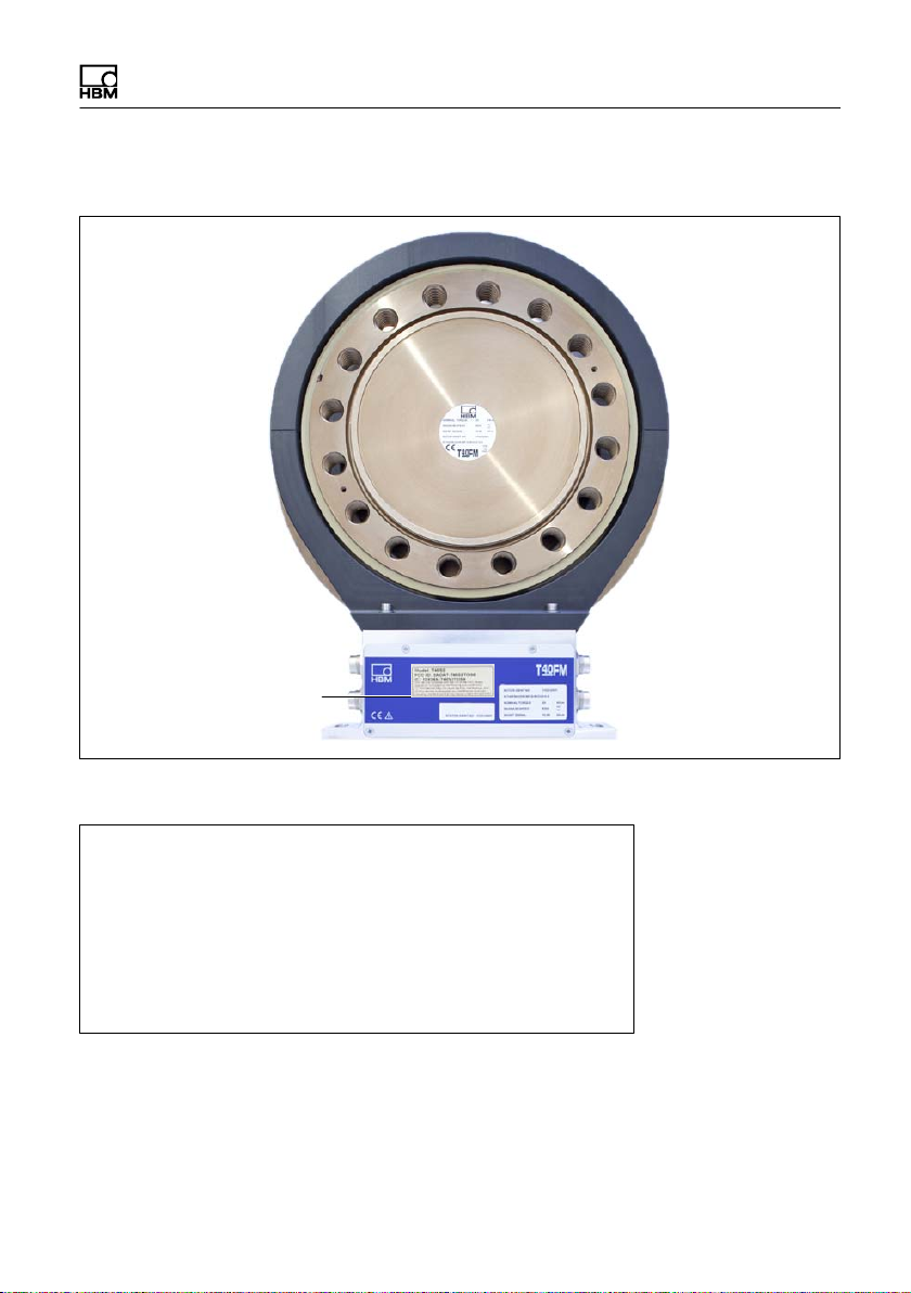
Label example with FCC ID and IC number.
Label
Safety information
Fig. 1.1 Location of the label on the stator of the device
Model: T40S7
FCC ID: 2ADAT-T40S7TOS9
IC: 12438AT40S7TOS9
This device complies with part 15 of the FCC Rules. Operation is
subject to the following two conditions: (1) This device may not
cause harmful interference, and (2) this device must accept any
interference received, including interference that may cause
undesired operation.
Fig. 1.2 Example of the label
T40FM A3276-11.0 HBM: public 5
Page 8

Safety information
Industry Canada for Option 7, Code S, H
This device complies with Industry Canada standard RSS210.
This device complies with Industry Canada license−exempt RSS stan
dard(s).Operation is subject to the following two conditions: (1) this device may
not cause interference, and (2) this device must accept any interference,
including interference that may cause undesired operation of the device.
Cet appareil est conforme aux norme RSS210 d’Industrie Canada.
Cet appareil est conforme aux normes d’exemption de licence RSS d’Industry
Canada. Son fonctionnement est soumis aux deux conditions suivantes : (1)cet
appareil ne doit pas causer d’interférence et (2) cet appareil doit accepter toute
interférence, notamment les interférences qui peuvent affecter son fonction
nement.
Appropriate use
The T40FM torque flange is used exclusively for torque, angle of rotation and
power measurement tasks within the load limits stipulated in the specifications.
Any other use is not appropriate.
Stator operation is only permitted when the rotor is installed.
The torque flange may only be installed by qualified personnel in compliance
with the specifications and with the safety requirements and regulations of
these mounting instructions. It is also essential to observe the applicable legal
and safety regulations for the application concerned. The same applies to the
use of accessories.
The torque flange is not intended for use as a safety component. Please also
refer to the section: "Additional safety precautions". Proper and safe operation
requires proper transportation, correct storage, siting and mounting, and careful
operation.
Load carrying capacity limits
The data in the technical data sheets must be complied with when using the
torque flange. The respective specified maximum loads in particular must never
6 A3276-11.0 HBM: public T40FM
Page 9

Safety information
be exceeded. For example, the values stated in the specifications must not be
exceeded, e.g. for
S Limit torque
S Longitudinal limit force, lateral limit force or limit bending moment
S Torque oscillation width
S Breaking torque
S Temperature limits
S Limits of the electrical load-carrying capacity.
Use as a machine element
The torque flange can be used as a machine element. When used in this man
ner, it must be noted that, to favor greater sensitivity, the transducer is not de
signed with the safety factors usual in mechanical engineering. Please refer
here to the section "Loading capacity limits" and to the specifications.
Accident prevention
According to the prevailing accident prevention regulations, once the trans
ducers have been mounted, a covering agent or cladding has to be fitted as
follows:
S The covering agent or cladding must not be free to rotate.
S The covering agent or cladding should prevent squeezing or shearing and
provide protection against parts that might come loose.
S Covering agents and cladding must be positioned at a suitable distance or
be so arranged that there is no access to any moving parts within.
S Covering agents and cladding must still be attached even if the moving
parts of the torque flange are installed outside people's movement and
working range.
The only permitted exceptions to the above requirements are if the torque
flange is already fully protected by the design of the machine or by existing
safety precautions.
T40FM A3276-11.0 HBM: public 7
Page 10

Safety information
Additional safety precautions
The torque flange cannot (as a passive transducer) implement any (safety-rel
evant) cutoffs. This requires additional components and constructive measures,
for which the installer and operator of the plant is responsible. The electronics
conditioning the measurement signal should be designed so that measurement
signal failure does not subsequently cause damage.
The scope of supply and performance of the transducer covers only a small
area of torque measurement technology. In addition, equipment planners, in
stallers and operators should plan, implement and respond to safety engineer
ing considerations in such a way as to minimize residual dangers. Pertinent
national and local regulations must be complied with.
General dangers of failing to follow the safety instructions
The torque flange corresponds to the state of the art and is reliable. Trans
ducers can give rise to residual dangers if they are incorrectly operated or inap
propriately mounted, installed and operated by untrained personnel. Every per
son involved with siting, starting-up, operating or repairing a torque flange must
have read and understood the mounting instructions and in particular the tech
nical safety instructions. The transducers can be damaged or destroyed by
non-designated use of the transducer or by non-compliance with the mounting
and operating instructions, these safety instructions or any other applicable
safety regulations (safety and accident prevention regulations), when using the
transducers. Transducers can break, particularly in the case of overloading.
The breakage of a transducer can also cause damage to property or injury to
persons in the vicinity of the transducer.
If the torque flange is not used according to the designated use, or if the safety
instructions or specifications in the mounting and operating instructions are ig
nored, it is also possible that the transducer may fail or malfunction, with the
result that persons or property may be adversely affected (due to the torques
acting on or being monitored by the torque flange).
8 A3276-11.0 HBM: public T40FM
Page 11

Safety information
Conversions and Modifications
The transducer must not be modified from the design or safety engineering
point of view except with our express agreement. Any modification shall ex
clude all liability on our part for any damage resulting therefrom.
Selling on
If the torque flange is sold on, these mounting instructions must be included
with the torque flange.
Qualified Personnel
Qualified personnel means persons entrusted with siting, mounting, starting up
and operating the product, who possess the appropriate qualifications for their
function.
This includes people who meet at least one of the three following requirements:
1. Knowledge of the safety concepts of automation technology is a require
ment and as project personnel, you must be familiar with these concepts.
2. As automation plant operating personnel, you have been instructed how to
handle the machinery. They are familiar with the operation of the equipment
and technologies described in this documentation.
3. As system startup engineers or service engineers, they have successfully
completed the training to qualify them to repair the automation systems. You
are also authorized to ground and label circuits and equipment and place
them in operation in accordance with safety engineering standards.
T40FM A3276-11.0 HBM: public 9
Page 12
Markings used
2 Markings used
2.1 The marking used in this document
Important instructions for your safety are specifically identified. It is essential to
follow these instructions in order to prevent accidents and damage to property.
Symbol Significance
WARNING
CAUTION
Note
Important
Tip
Information
Emphasis
See …
This marking warns of a potentially dangerous situ
ation in which failure to comply with safety require
ments can result in death or serious physical injury.
This marking warns of a potentially dangerous situ
ation in which failure to comply with safety require
ments can result in slight or moderate physical injury.
This marking draws your attention to a situation in
which failure to comply with safety requirements
could lead to damage to property.
This marking draws your attention to important in
formation about the product or about handling the
product.
This marking indicates application tips or other in
formation that is useful to you.
This marking draws your attention to information
about the product or about handling the product.
Italics are used to emphasize and highlight text and
identify references to sections, diagrams, or external
documents and files.
10 A3276-11.0 HBM: public T40FM
Page 13
2.2 Symbols on the transducer
CE mark
The CE mark enables the manufacturer to guarantee that
the product complies with the requirements of the relev
ant EC directives (the Declaration of Conformity can be
found on the HBM website at www.hbm.com under HBM
doc).
Label example
Markings used
Model: T40S7
FCC ID: 2ADAT-T40S7TOS9
IC: 12438AT40S7TOS9
This device complies with part 15 of the
FCC Rules. Operation is subject to the
following two conditions: (1) This device
may not cause harmful interference, and
(2) this device must accept any interfer
ence received, including interference that
may cause undesired operation.
Label example with FCC ID and IC number. Location of
the label on the stator device.
Statutory waste disposal mark
The electrical and electronic devices that bear this sym
bol are subject to the European waste electrical and elec
tronic equipment directive 2002/96/EC. The symbol indic
ates that, in accordance with national and local
environmental protection and material recovery and re
cycling regulations, old devices that can no longer be
used must be disposed of separately and not with normal
household garbage, see also Chapter 11, Page 48.
T40FM A3276-11.0 HBM: public 11
Page 14

Applications
3 Applications
The T40FM torque flange measures static and dynamic torques on stationary
and rotating shafts. Test beds can be extremely compact because of the com
pact design of the transducer. This offers a very wide range of applications.
The T40FM torque flange is reliably protected against electromagnetic interfer
ence. It has been tested according to harmonized European standards and/or
complies with US and Canadian standards. The product carries the CE mark
and/or FCC label.
12 A3276-11.0 HBM: public T40FM
Page 15
Structure and Mode of Operation
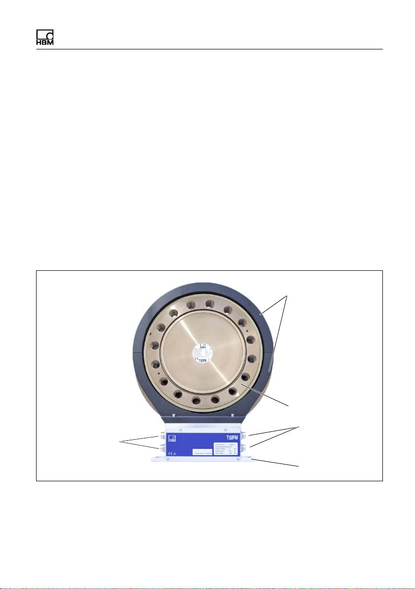
4 Structure and Mode of Operation
The torque flange consists of two separate parts: the rotor and the stator. The
rotor comprises the measuring body and the signal transmission elements.
Strain gauges (SGs) are installed on the measuring body. The rotor electronics
for transmitting the bridge excitation voltage and the measurement signal are
located centrally in the flange. The transmitter coils for contactless transmission
of excitation voltage and measurement signal are located on the measuring
body's outer circumference. The signals are sent and received by a separable
antenna ring. The antenna ring is mounted on a housing that contains the elec
tronics for voltage adaptation and the signal conditioning.
Connector plugs for the torque and rotational speed signals, the voltage supply
and digital output, are located on the stator. The antenna segments (ring)
should be mounted concentrically around the rotor (see Chapter 5).
Antenna segments
Rotor
Connector plugs
Connector plugs
Identification plate
Fig. 4.1 Mechanical construction without a rotational speed measuring system,
Option 6, Code 0
Stator housing
T40FM A3276-11.0 HBM: public 13
Page 16
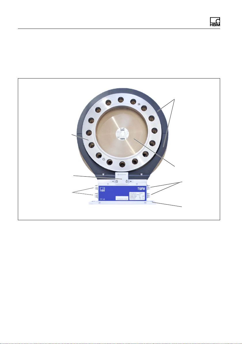
Structure and Mode of Operation
The rotational speed sensor is mounted on the stator in Option 6 with a rota
tional speed measuring system. The customer mounts the rotational speed disc
between the measuring body and customer flange. The rotational speed is
measured magnetically with an AMR sensor and magnetic tape.
Antenna segments
Rotational speed disc
Sensor head for
measuring rotational
speed
Connector plugs
Identification plate
Rotor
Connector
plugs
Stator
housing
Fig. 4.2 Mechanical construction with a speed measuring system, Option 6, Code 1
14 A3276-11.0 HBM: public T40FM
Page 17

Mechanical installation
5 Mechanical installation
5.1 Important precautions during installation
Notice
A torque flange is a precision measuring element and therefore needs careful
handling. Dropping or knocking the transducer may cause permanent damage.
Make sure that the transducer cannot be overloaded, including while it is being
mounted.
S Handle the transducer with care.
S Check the effect of bending moments, critical rotational speeds and natural
torsional vibrations, to prevent the transducer being overloaded by reson
ance sharpness.
S Make sure that the transducer cannot be overloaded.
WARNING
There is a danger of the transducer breaking if it is overloaded. This can cause
danger for the operating personnel of the system in which the transducer is in
stalled.
Implement appropriate safety measures to avoid overloads and to protect
against resulting dangers.
S Use a threadlocker (medium strength, e.g. LOCTITE) to glue the screws into
the counter thread to exclude prestressing loss due to screw slackening, in
the event of alternating loads.
S Comply with the mounting dimensions to enable correct operation.
T40FM A3276-11.0 HBM: public 15
Page 18

Mechanical installation
An appropriate shaft flange enables the T40FM torque flange to be mounted
directly. It is also possible to mount a joint shaft or relevant compensating ele
ment directly on the rotor (using an intermediate flange when required). Under
no circumstances should the permissible limits specified for bending moments,
lateral and longitudinal forces be exceeded. Due to the T40FM torque flange's
high torsional stiffness, dynamic shaft train changes are kept to a minimum.
Important
Even if the unit is installed correctly, the zero point adjustment made at the fact
ory can shift by up to approx. 0.5% of the characteristic value. If this value is
exceeded, we advise you to check the mounting conditions. If the residual zero
offset when the unit is removed is greater than 1% of the sensitivity, please
send the transducer back to the Darmstadt factory for testing.
5.2 Conditions on site
The T40FM torque flange must be protected against coarse dirt particles, dust,
oil, solvents and moisture.
There is wide ranging compensation for the effects of temperature on the out
put and zero signals of the transducer (see Chapter 14 "Specifications"). If
there are no static temperature ratios, for example, because of the temperature
differences between the measuring body and the flange, the values given in the
specifications can be exceeded. In this case, ensure static temperature ratios
by cooling or heating, depending on the application. As an alternative, check if
thermal decoupling is possible, e.g. by means of heat radiating elements such
as multiple disc couplings.
5.3 Installation orientation
The torque flange can be installed with any orientation.
With clockwise torque, the output frequency is 60 … 90 kHz for Option 5, code
DU2 (Option 5, code SU2: 10 … 15kHz; Option HU2: 240 … 360kHz). In con
junction with HBM amplifiers or when using the voltage output, a positive output
16 A3276-11.0 HBM: public T40FM
Page 19

Mechanical installation
signal (0 V …+10 V) is present. In the case of the rotational speed measuring
system, an arrow is attached to the stator housing to clearly define the direction
of rotation: if the measurement flange turns in the direction of the arrow, con
nected HBM measuring amplifiers deliver a positive output signal.
5.4 Installation options
There are basically two options for mounting the torque flange: with or without
dismantling the antenna ring. We recommend mounting as described in
Chapter 5.4.1. If mounting in accordance with Chapter 5.4.1 is not possible,
(e.g. in the case of subsequent stator replacement), you will have to dismantle
the antenna ring. It is essential in this case to comply with the notes on assem
bling the antenna segments (see Chapter 5.4.2).
T40FM A3276-11.0 HBM: public 17
Page 20
Mechanical installation
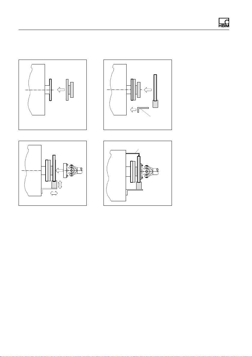
5.4.1 Installation without dismantling the antenna ring
Mounting supplied by
customer
1. Install rotor 2. Install stator
Support supplied by customer
3. Finish shaft train installation
4. Fit support
18 A3276-11.0 HBM: public T40FM
Page 21
Mechanical installation
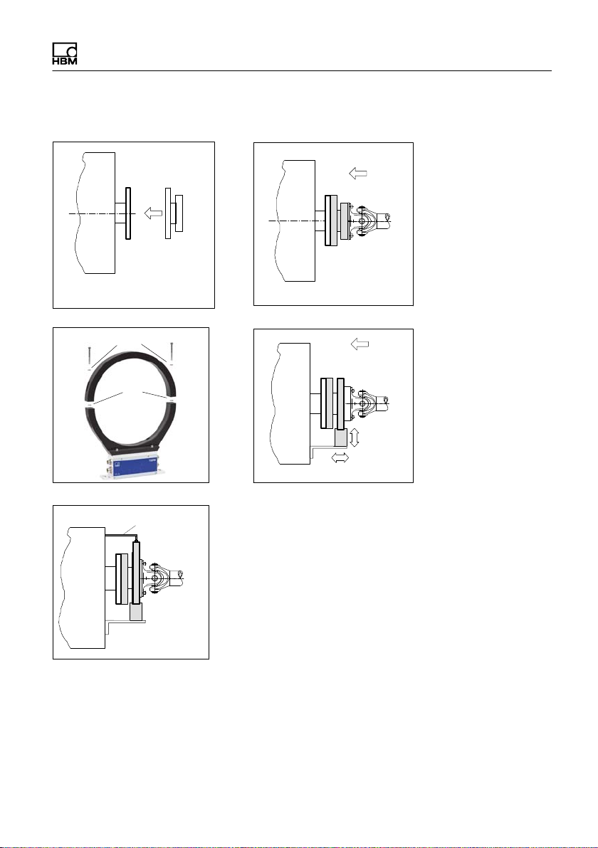
5.4.2 Installation with subsequent antenna ring mounting
1. Install rotor
Washers
3. Dismantle antenna segment
Support supplied by customer
Fan-type
lock
washers
4. Fit support
2. Install shaft train
4. Install antenna segment
T40FM A3276-11.0 HBM: public 19
Page 22
Mechanical installation
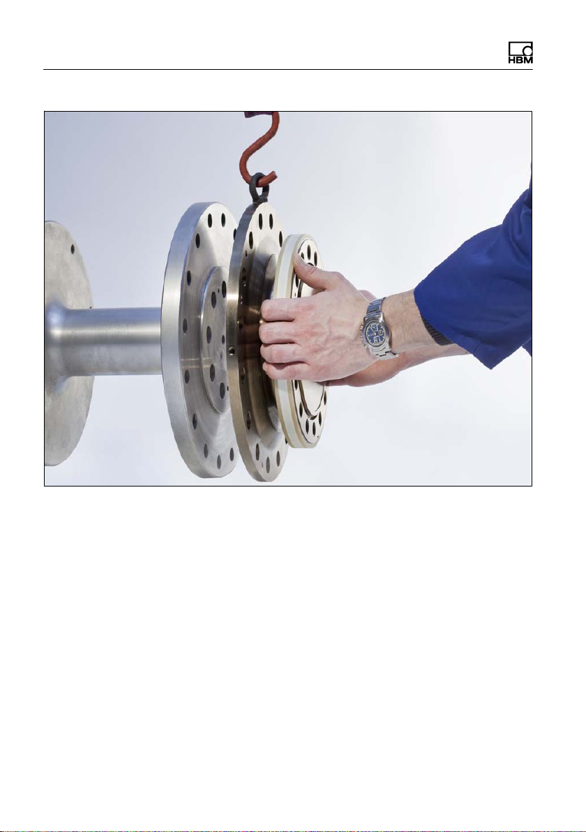
5.5 Preparing for the rotor mounting
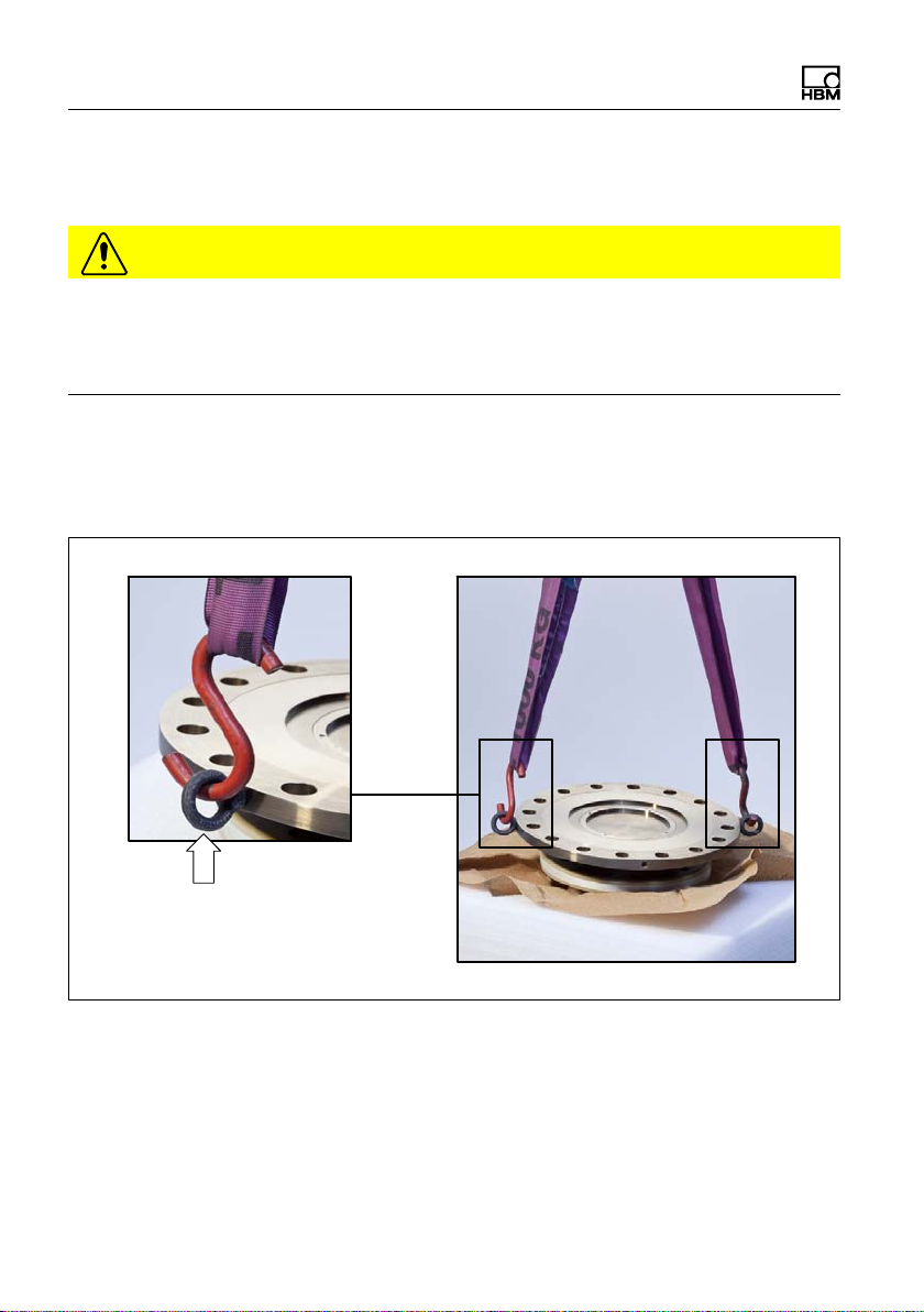
CAUTION
The rotor is very heavy (depending on measuring range: 18kg … 39kg)!
Use a crane or other suitable lifting equipment to lift it out of its packaging and
install it.
Two eye bolts are screwed into the rotor as transport and mounting aids. Hook
the lifting equipment to these eye bolts as this ensures that the rotor is lifted
horizontally out of the packaging (see Fig. 5.1).
Transport and mounting eye bolts
Fig. 5.1 Transport and mounting eye bolts on the rotor
1. Lift the rotor out of the packaging, rotate horizontally by 180_, so that flange
B is pointing upwards (see Fig. 5.1).
20 A3276-11.0 HBM: public T40FM
Page 23
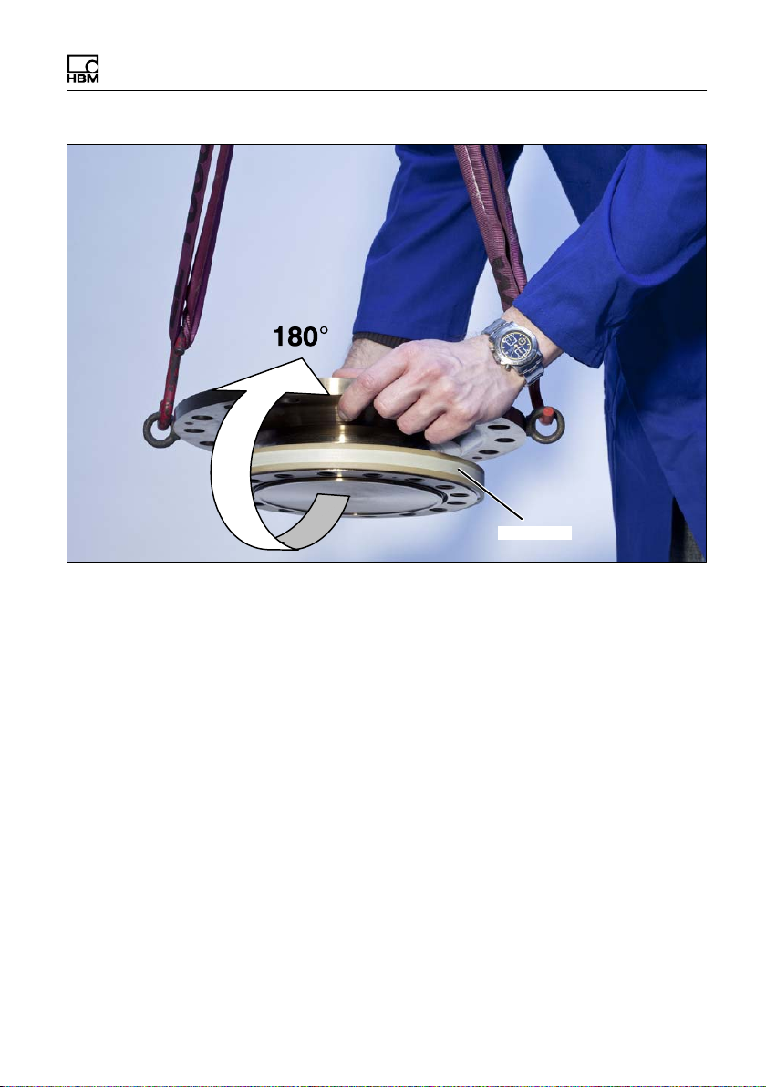
Fig. 5.2 Rotating the rotor
Mechanical installation
Flange B
2. Place the rotor carefully onto a clean and stable table.
3. If the rotor is to be installed horizontally as shown in Fig. 5.3, remove one
mounting eye bolt. Both mounting eye bolts can initially remain in the flange
for vertical installation.
T40FM A3276-11.0 HBM: public 21
Page 24
Mechanical installation
Fig. 5.3 Rotor installation (horizontal)
4. Clean the plane faces of the transducer flange and the counter flange.
For safe torque transfer, the faces must be clean and free from grease. Use
a piece of cloth or paper soaked in solvent. Make sure that no solvent drips
into the inside of the transducer and that the transmitter coils are not dam
aged during cleaning.
5. Fasten the lifting equipment to the mounting eye bolt(s).
6. Carefully lift up the rotor and move it to the mounting position (see Fig. 5.1).
22 A3276-11.0 HBM: public T40FM
Page 25

Mechanical installation
5.6 Mounting the rotor
Tip
Usually the rotor type plate is no longer visible after installation. This is why we
include with the rotor additional stickers with the important characteristics,
which you can attach to the stator or any other relevant test-bench compon
ents. You can then refer to them whenever there is anything you wish to know,
such as the shunt signal. To explicitly assign the data, the identification number
and the size are engraved on the rotor flange, where they can be seen from
outside.
Notice
Make sure during installation that you do not damage the measuring zone
marked in Fig. 5.4 by using it to support tools or knocking tools against it when
tightening screws, for example. This can damage the transducer and produce
measurement errors, or even destroy the transducer.
1. Prior to installation, clean the plane faces of the transducer flange and the
counter flange.
For safe torque transfer, the faces must be clean and free from grease. Use
a piece of cloth or paper soaked in solvent. When cleaning, make sure that
you do not damage the transmitter winding.
T40FM A3276-11.0 HBM: public 23
Page 26

Mechanical installation
Measuring zone
Flange A
Fig. 5.4 Bolted rotor connection
Hexagon socket screw (Z)
DIN EN ISO 4762 (10.9)
Fastening bolt (10.9);
note maximum thread reach Y!
2. For the connection of flange A (see Fig. 5.4), use DIN EN ISO 4762
property class 10.9 hexagon socket screws of a suitable length (dependent
on the connection geometry, see Tab. 5.1 on Page 25).
We recommend fillisterhead screws DIN EN ISO 4762, blackened, smooth
headed, permitted size and shape variance in accordance with DIN ISO
4759, Part 1, product class A.
3. Fasten all screws with the specified torque (Tab. 5.1 on Page 25).
4. Now remove the eye bolt(s) used for transportation and mounting.
Important
Keep them in a safe place for future dismounting.
24 A3276-11.0 HBM: public T40FM
Page 27

Mechanical installation
5. There are relevant tapped holes on flange B for continuing the shaft train
mounting. Again use screws of property class 10.9 and tighten them with
the prescribed torque, as specified in Tab. 5.1, Page 25.
Important
Use a threadlocker (medium strength, e.g. LOCTITE) to glue the screws into
the counter thread to exclude prestressing loss due to screw slackening, in the
event of alternating loads.
Notice
Comply with the maximum screw-in depth as per Tab. 5.1, Page 25. Otherwise
significant measurement errors may result from torque shunt, or the transducer
may be damaged.
Measuring
range
kNVm Z
15
20
25
30
40
50
60
70
80
1)
DIN EN ISO 4762; black/oiled/m
Tab. 5.1 Fastening screws
Fastening screws Maximum thread
reach Y of screws
in flange B
1)
M18
M20 40 560
M22 45 760
Property class mm NVm
30 400
10.9
=0.125
tot
Prescribed
tightening
moment
T40FM A3276-11.0 HBM: public 25
Page 28
Mechanical installation
Important
Dry screw connections can result in different and higher friction factors (see
VDI 2230, for example). This means a change to the required tightening mo
ments.
The required tightening moments can also change if you use screws with a sur
face or property class other than that specified in Tab. 5.1, as this affects the
friction factor.
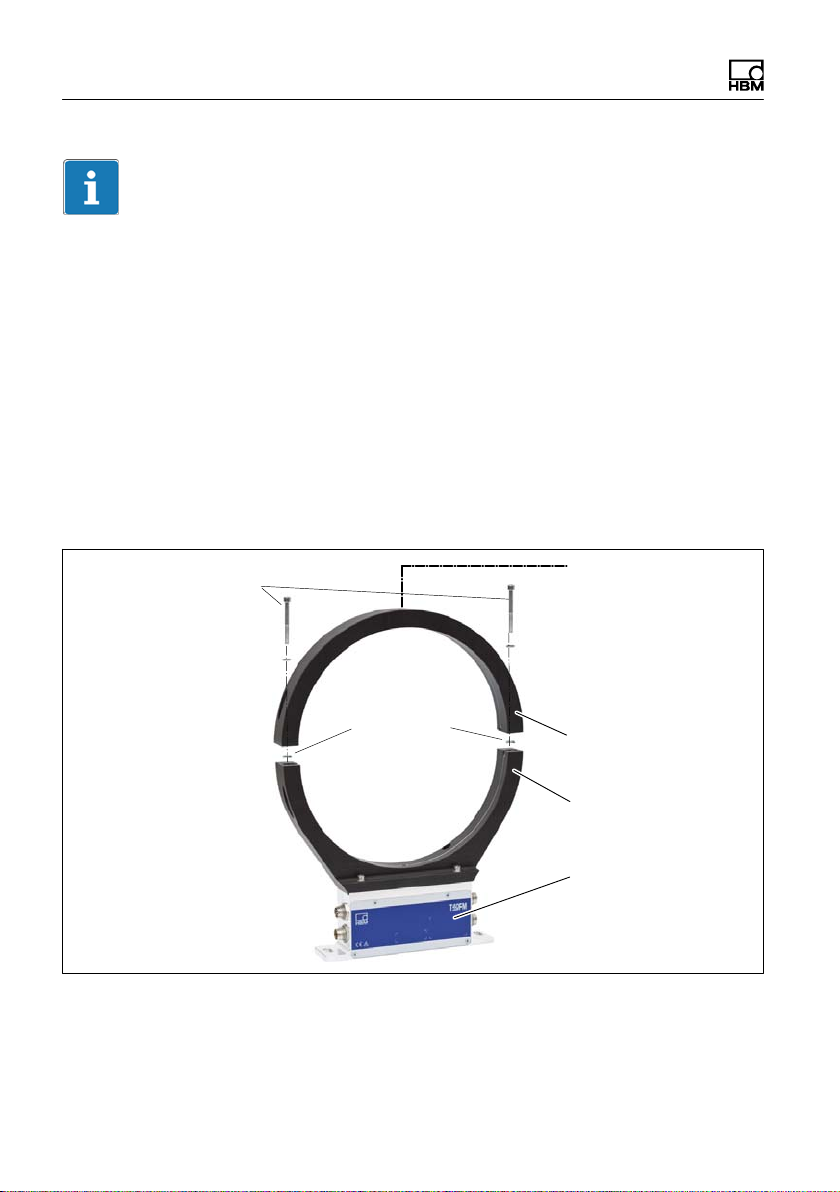
5.7 Installing the stator
On delivery, the stator has already been installed and is ready for operation.
The upper antenna segment can be separated from the stator, for example, for
maintenance or to facilitate stator mounting.
Antenna segment screws
with washers (M5)
Fan-type lock
washers
Fig. 5.5 Bolted connection of the antenna segments on the stator
M5 hole for fixing the
antenna segment
upper
Antenna segments
lower
Stator housing
26 A3276-11.0 HBM: public T40FM
Page 29
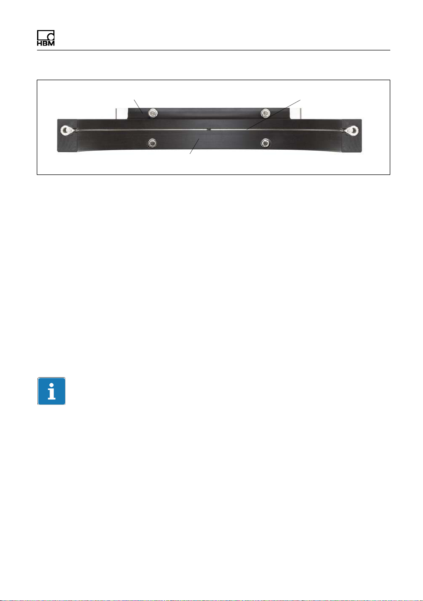
Mechanical installation
Stator housing
Lower antenna segment
Fig. 5.6 Stator housing and lower antenna segment with antenna wire
Antenna wire
1. Undo and remove the bolted connections (M5) on the upper antenna seg
ment.
There are fan-type lock washers between the antenna segments: make sure
that they do not get lost.
2. Use an appropriate mounting base to install the stator housing in the shaft
train, so that there is sufficient opportunity for horizontal and vertical adjust
ments. Do not fully tighten the bolts yet.
3. Now use two hexagon socket screws to mount the upper antenna segment
removed in Point 1 on the lower antenna segment.
Make sure that the two fan-type lock washers are inserted between the an
tenna segments (these ensure that there is a defined contact resistance)!
Important
To make sure that they function perfectly, the fan-type lock washers (A5.3-FST
DIN 6798 ZN/galvanized) must be replaced after the bolted antenna connection
has been loosened three times.
4. Now tighten all the bolted antenna segment connections with a tightening
torque of 5 N⋅m.
5. Then align the antenna to the rotor in such a way that the antenna encloses
the rotor more or less coaxially and the antenna wire in the axial direction
has the same position as the center of the transmitter winding on the rotor.
T40FM A3276-11.0 HBM: public 27
Page 30

Mechanical installation
Fig. 5.7 Alignment of the rotor with the stator
6. Now fully tighten the bolted stator housing connection.
Prevention of axial stator oscillation
Depending on the operating conditions, the stator may be induced to oscillate.
This effect is dependent on:
S the rotational speed,
S the antenna diameter (depends in turn on the measuring range),
S the design of the machine base.
Important
To prevent this axial oscillation, the antenna ring requires additional support by
the customer. There is a socket (with an M5 internal thread) on the upper an
tenna segment, which can be used for a suitable clamping device (see
Fig. 5.8). If this is the case, the cable plug also needs some support, as shown
in the construction example in Fig. 5.9.
28 A3276-11.0 HBM: public T40FM
Page 31

Mechanical installation
Fig. 5.8 Construction example for supporting the antenna ring
Fig. 5.9 Construction example for connector terminals (for two plugs)
T40FM A3276-11.0 HBM: public 29
Page 32

Mechanical installation
5.8 Mounting the rotational speed flange (rotational speed measuring system only)
The rotational speed disc (intermediate flange) is ready-mounted on the rotor at
the factory, with two (M4) screws.
Rotational speed disc
M4 fixing screws
Sensor head
for measuring
rotational
speed
Sensor head
for reference
signal
Fig. 5.10 Torque transducer with rotational speed measurement, optional reference
signal, Option 6, Code A
Notice
The two (M4) screws are only used to fix the rotational speed disc. The meas
urement flange and the attached speed measuring system may therefore be
rotated only after mounting.
30 A3276-11.0 HBM: public T40FM
Page 33

Mechanical installation
Important
The speed measuring system uses a magnetic measuring principle. In applica
tions where high magnetic field strengths can occur, e.g. eddy-current brakes,
implement suitable measures to ensure that the maximum permissibly mag
netic field strength cannot be exceeded (see Chapter 14 "Specifications",
Page 63).
Stator alignment (rotational speed measuring system, optionally with
reference signal)
The rotational speed measuring system is correctly aligned when the stator is
precisely aligned for torque measurement. A reduction in the distance between
the sensor head and magnetic ring can in some cases improve the signal qual
ity when the rotor is centrally positioned in the stator. To do this, loosen both
screws on the sensor head and push the sensor head in parallel as marked
with the arrows in Fig. 5.11.
The sensor for recording the reference signal is permanently set and must not
be adjusted.
T40FM A3276-11.0 HBM: public 31
Page 34

Mechanical installation
Do not adjust
Sensor head
screws
Fig. 5.11 Torque transducer with speed disc and sensor head, and reference signal
(optional), Option 6, Code A
32 A3276-11.0 HBM: public T40FM
Page 35

Electrical Connection
6 Electrical Connection
6.1 General information
S With extension cables, make sure that there is a proper connection with
minimum contact resistance and good insulation.
S All cable connectors or swivel nuts must be fully tightened.
Important
Transducer connection cables from HBM with plugs attached are identified in
accordance with their intended purpose (Md or n). When cables are shortened,
inserted into cable ducts or installed in control cabinets, this identification can
get lost or become concealed. So the cables must be marked beforehand, just
in case.
6.2 EMC protection
Important
The transducers are EMC-tested in accordance with EC directives and identi
fied by CE certification. However, you must connect the shield of the connec
tion cable on the shielding electronics enclosure in order to achieve EMC pro
tection for the measuring chain.
Special electronic coding methods are used to protect the purely digital signal
transmission between the transmitter head and the rotor from electromagnetic
interference.
The cable shield is connected with the transducer housing. This encloses the
measurement system (without the rotor) in a Faraday cage when the shield is
laid flat at both ends of the cable. With other connection techniques, an
EMCproof shield should be applied in the wire area, and this shielding should
T40FM A3276-11.0 HBM: public 33
Page 36

Electrical Connection
also be connected extensively (also see HBM Greenline Information, brochure
i1577).
Electrical and magnetic fields often induce interference voltages in the measur
ing circuit. Therefore:
S Use shielded, low-capacitance measurement cables only (HBM cables fulfill
both conditions).
S Only use plugs that meet EMC guidelines.
S Do not route the measurement cables parallel to power lines and control
circuits. If this is not possible, protect the measurement cable with e.g. steel
conduit.
S Avoid stray fields from transformers, motors and contact switches.
S Do not ground the transducer, amplifier and indicator more than once.
S Connect all the devices in the measuring chain to the same protective earth
conductor.
S In the case of interference due to potential differences (compensating cur
rents), the connections between supply voltage zero and housing ground
must be broken at the amplifier and a potential equalization line established
between the stator housing and the amplifier housing (copper conductor, at
least 10 mm
2
wire crosssection).
S Should differences in potential between the machine rotor and stator, be
cause of unchecked leakage, for example, cause interference, this can usu
ally be overcome by connecting the rotor definitively to ground, e.g. with a
wire loop. The stator must be connected to the same (ground) potential.
6.3 Pin Assignment
The stator housing has two 7-pin plugs, an 8-pin plug and a 16-pin plug.
The supply voltage connections and shunt signal connections of plugs 1 and 3
are each electrically interconnected, but are protected against compensating
currents by diodes. There is also a self-resetting fuse (multifuse) to protect the
supply voltage connections against overload by the stator.
34 A3276-11.0 HBM: public T40FM
Page 37

Electrical Connection
Assignment for plug 1 - Supply voltage and frequency output signal
61
Device plug
5
72
3
4
Top view
KAB153 KAB149 KAB178
Plug
Assignment Color
pin
code
D‐SUB‐
plug
pin
Torque measurement signal (frequency
1
output; 5 V
Supply voltage 0 V;
2
2),3
)
wh 13 5
bk 5 -
3 Supply voltage 18 V to 30 V bu 6 -
Torque measurement signal (frequency
4
output; 5 V
Measurement signal 0 V; symmetrical
5
2),3
)
rd 12 10
gy 8 6
6 Shunt signal trigger 5 V to 30 V gn 14 15
Shunt signal 0 V
7
gy 8 -
Shielding connected to housing ground
1)
Bridge between 4 + 9
2)
RS-422 complementary signals; with cable lengths exceeding 10 m, we recommend using a
termination resistor R = 120 ohms between the (wh) and (rd) wires.
3)
RS‐422: pin 1 corresponds to A, pin 4 corresponds to B.
1)
HD‐SUB‐
plug
pin
T40FM A3276-11.0 HBM: public 35
Page 38

Electrical Connection
Notice
Torque flanges are only intended for operation with a DC supply voltage. They
must not be connected to older HBM amplifiers with square-wave excitation.
This could destroy the connection board resistors or cause other faults in the
amplifiers.
36 A3276-11.0 HBM: public T40FM
Page 39

Electrical Connection
Assignment for plug 2 - Rotational speed measurement system
2
5
3
4
Device plug
8
1
Top view
6
7
KAB154 KAB150 KAB179
Plug
Assignment Color
pin
Rotational speed measurement signal
1
(pulse string, 5 V; 0°)
code
2)
rd 12 10
D-SUB-
plug pin
2 Not in use bl - -
Rotational speed measurement signal
3
(pulse string, 5 V; 90° phase shifted)
2)
gy 15 8
4 Not in use bl - 5 Not in use vi - -
Rotational speed measurement signal
6
(pulse string, 5 V; 0°)
Rotational speed measurement signal 2)
7
(pulse string, 5 V; 90° phase shifted)
8 Operating voltage zero bk/bl
2)
wh 13 5
gn 14 7
3)
8 6
Shielding connected to housing ground
1)
Bridge between 4 + 9
2)
RS-422 complementary signals; with cable lengths exceeding 10 m, we recommend using a
termination resistor of R = 120 ohms.
3)
KAB163/KAB164: color code brown (bn)
1)
HD-SUB-
plug pin
T40FM A3276-11.0 HBM: public 37
Page 40

Electrical Connection
Assignment for plug 2 - Rotational speed measurement system with
reference signal
2
5
3
4
Device plug
8
1
Top view
6
7
KAB164 KAB163 KAB181
Plug
Assignment Color
pin
Rotational speed measurement signal
1
(pulse string, 5 V)
2 Reference signal (1 pulse/revolution, 5 V)
Rotational speed measurement signal
3
(pulse string, 5 V; 90° phase shifted)
4 Reference signal (1 pulse/revolution, 5 V)
code
2)
2)
rd 12 10
2)
bl 2 3
gy 15 8
2)
bl 3 2
D-SUB-
plug pin
5 Not in use vi - -
Rotational speed measurement signal
6
(pulse string, 5 V; 0°)
Rotational speed measurement signal
7
(pulse string, 5 V; 90° phase shifted)
8 Operating voltage zero bl
2)
2)
wh 13 5
gn 14 7
3)
8 6
Shielding connected to housing ground
1)
Bridge between 4 + 9
2)
RS-422 complementary signals; with cable lengths exceeding 10 m, we recommend using a
termination resistor of R = 120 ohms.
3)
KAB163/KAB164: color code brown (bn)
1)
HD-SUB-
plug pin
38 A3276-11.0 HBM: public T40FM
Page 41

Electrical Connection
Pin 1
Pin 6
Pin 3
Pin 7
Pin 2
Pin 4
Fig. 6.1 Rotational speed signals at plug 2 (rotational speed in the direction of the
arrow)
T40FM A3276-11.0 HBM: public 39
Page 42

Electrical Connection
Pin 1
Pin 6
Pin 3
Pin 7
Pin 2
Pin 4
Fig. 6.2 Rotational speed signals at plug 2 (rotational speed against the direction of
the arrow)
40 A3276-11.0 HBM: public T40FM
Page 43

Electrical Connection
Assignment for plug 3 - Supply voltage and voltage output signal
61
5
72
3
4
Plug pin Assignment Color code
1
2
3 Supply voltage 18 V to 30 V DC bl
4 Torque measurement signal (voltage output; ±10 V) rd
5 Not in use gy
6 Shunt signal trigger 5 V to 30 V gn
7
Device plug
Top view
Torque measurement signal
(voltage output; 0 V)
Supply voltage 0 V;
Shunt signal 0 V;
Shielding connected to housing ground
wh
bk
gy
Assignment for plug 4
TMC - only for connection to the TIM 40 Torque Interface Module within HBM.
6.4 Supply Voltage
The transducer must be operated with a separated extra-low voltage (supply
voltage 18 … 30 V
). You can supply one or more torque flanges within a test
DC
bench at the same time. Should the device be operated on a DC voltage net
1)
, additional precautions must be taken to discharge excess voltages.
work
1)
Distribution system for electrical energy with greater physical expansion (over several test
benches, for example) that may possibly also supply consumers with high nominal (rated)
currents.
T40FM A3276-11.0 HBM: public 41
Page 44

Electrical Connection
The information in this Chapter relates to the self-contained operation of the
T40FM without HBM system solutions.
The supply voltage is electrically isolated from signal outputs and shunt signal
inputs. Connect a separated extra-low voltage of 18 V … 30 V to pin 3 (+) and
pin 2 (
KAB 8/00-2/2/2 and the appropriate sockets (see Accessories). The cable can
be up to 50m long for voltages ≥24V, otherwise it can be up to 20m long.
If the permissible cable length is exceeded, you can feed the supply voltage in
parallel over two connection cables (plugs 1 and 3). This enables you to double
the permissible length. Alternatively, install an on-site power supply.
The instant you switch on, a current of up to 4 A may flow and this may switch
off power packs with electronic current limiters.
) of plugs 1 or 3. We recommend that you use HBM cable
Important
42 A3276-11.0 HBM: public T40FM
Page 45

Shunt signal
7 Shunt signal
The T40FM torque flange delivers an electrical shunt signal that can be activ
ated from the amplifier for measuring chains with HBM components. The trans
ducer generates a shunt signal of about 50% of the nominal (rated) torque; the
precise value is specified on the type plate. After activation, adjust the amplifier
output signal to the shunt signal supplied by the connected transducer, to adapt
the amplifier to the transducer.
Information
The transducer should not be under load when the shunt signal is being meas
ured, as the shunt signal is mixed additively.
Triggering the shunt signal
Applying a separated extra-low voltage of 5 … 30 V to pins 6 (+) and 7 (
plug 1 or 3, triggers the shunt signal.
The nominal (rated) voltage for triggering the shunt signal is 5 V (triggering at U
> 2.5 V), but when voltages are less than 0.7 V, the transducer is in measuring
mode. The maximum permissible voltage is 30 V, current consumption at nom
inal (rated) voltage is approx. 2 mA and at maximum voltage, approx. 18 mA.
The voltage for triggering the shunt signal is electrically isolated from the supply
and measuring voltage.
Tip
The shunt signal can be triggered by the amplifier or via the operating software
in HBM system solutions.
T40FM A3276-11.0 HBM: public 43
) at
Page 46

Functionality testing
8 Functionality testing
You can check the functionality of the rotor and the stator from the LEDs on the
stator.
LED A, rotor status
LED B, stator status
Fig. 8.1 LEDs on the stator housing, Option 7, Code S and FCC option
Important
Once the supply voltage is applied, the torque transducer needs up to a further
4 seconds to be ready for operation.
8.1 Rotor status, LED A (upper LED)
Color Significance
Green (pulsating) Internal rotor voltage values ok
Flashing orange Rotor and stator mismatched (an increasing flashing
frequency indicates the degree of misalignment)
=> Correct the rotor/stator alignment
44 A3276-11.0 HBM: public T40FM
Page 47

Functionality testing
SignificanceColor
Pulsating orange Rotor status cannot be defined
=> Correct the rotor/stator alignment
If the LED still pulsates orange, it is possible that there is a
hardware defect. The measurement signals reflect the level of
the fault.
Red (pulsating) Rotor voltage values not ok.
=> Correct the rotor/stator alignment
If the LED still pulsates red, it is possible that there is a
hardware defect. The measurement signals reflect the level of
the fault.
Pulsating means that the LED goes dark for about 20 ms every second (sign of
life), making it possible to detect that the transducer is functioning.
8.2 Stator status, LED B (lower LED)
Color Significance
Green
(permanently lit)
Green, intermittently
orange.
Numerous
synchronization
defects:
Measurement signal transmission and internal stator voltages
ok
Orange until end of defective transmission if y5 incorrect
measured values are transmitted in succession. The
measurement signals reflect the level of the defect status for
the duration of the transmission defect + for approx. another
3.3ms.
permanently orange
Orange
(permanently lit)
Permanently disrupted transmission, the measurement
signals reflect the level of the fault. (f
= 0 Hz, U
out
= defect
out
level).
=> Correct the rotor/stator alignment.
Red
(permanently lit)
Internal stator defect, the measurement signals reflect the
level of the fault (f
= 0 Hz, U
out
= defect level).
out
T40FM A3276-11.0 HBM: public 45
Page 48

Loading capacity
9 Loading capacity
Nominal torque can be exceeded statically up to the limit torque. If the nominal
torque is exceeded, additional irregular loading is not permissible. This includes
longitudinal forces, lateral forces and bending moments. Limit values can be
found in Chapter 14 "Specifications" on Page 63.
Measuring dynamic torque
The torque flange can be used to measure static and dynamic torque. The fol
lowing apply to the measurement of dynamic torque:
S The T40FM calibration performed for static measurements is also valid for
dynamic torque measurements.
S The natural frequency f
pends on the moments of inertia J
of the mechanical measuring arrangement de
0
and J2 of the connected rotating masses
1
and the torsional stiffness of the T40FM.
Use the equation below to approximately determine the natural frequency f
the mechanical measuring arrangement:
f
= natural frequency in Hz
f0+
1
· cT·
2p
Ǹ
ǒ
J
1
)
Ǔ
J
2
1
1
0
J2= mass moment of inertia in kg⋅m
J
1,
c
= torsional stiffness in N⋅m/rad
T
2
S The permissible mechanical vibration bandwidth (peak-peak) can also be
found in the specifications.
of
0
46 A3276-11.0 HBM: public T40FM
Page 49

Maintenance
Nominal (rated) torque M
a %
+ M
nom
0
- M
nom
as
nom
Vibration bandwidth
Vibration bandwidth
Fig. 9.1 Permissible dynamic loading
10 Maintenance
The T40FM torque flanges are maintenance-free.
200% oscillation
Time t
Vibration bandwidth
width
T40FM A3276-11.0 HBM: public 47
Page 50

Waste disposal and environmental protection
11 Waste disposal and environmental protection
All electrical and electronic products must be disposed of as hazardous waste.
The correct disposal of old equipment prevents ecological damage and health
hazards.
Statutory waste disposal mark
The electrical and electronic devices that bear this sym
bol are subject to the European waste electrical and elec
tronic equipment directive 2002/96/EC. The symbol indic
ates that, in accordance with national and local
environmental protection and material recovery and re
cycling regulations, old devices that can no longer be
used must be disposed of separately and not with normal
household garbage.
As waste disposal regulations may differ from country to country, we ask that
you contact your supplier to determine what type of disposal or recycling is leg
ally applicable in your country.
Packaging
The original packaging of HBM devices is made from recyclable material and
can be sent for recycling. Store the packaging for at least the duration of the
warranty. In the case of complaints, the torque flange must be returned in the
original packaging.
For ecological reasons, empty packaging should not be returned to us.
48 A3276-11.0 HBM: public T40FM
Page 51

Dimensions
12 Dimensions
12.1 T40FM without speed measurement, Option 6, Code 0
12.1.1 T40FM 15kNm - 25kNm
Dimensions in mm (1 mm = 0.03937)
Dimensions without tolerances, per
DIN ISO 2768-mk
Mounting dimensions
Outer rotor Ø
Inner stator Ø
for axial locking
T40FM A3276-11.0 HBM: public 49
Page 52

Dimensions
T40FM 15kNm - 25kNm, continued
Internal centering
Rotor
Rotor flange (thread
reach)
Stator
Center of gravity
External centering
Partial sections cut
A-A
Dimensions without tolerances, per DIN ISO 2768-mk
Dimensions in mm (1 mm = 0.03937)
Alignment plane rotor - stator
Outer rotor Ø
50 A3276-11.0 HBM: public T40FM
Page 53

12.1.2 T40FM 30kNm - 50kNm
Dimensions in mm (1 mm = 0.03937)
Dimensions without tolerances, per DIN ISO 2768-mk
Mounting dimensions
Dimensions
Outer rotor Ø
Inner stator Ø
for axial locking
T40FM A3276-11.0 HBM: public 51
Page 54

Dimensions
T40FM 30kNm - 50kNm, continued
Dimensions in mm (1 mm = 0.03937)
Dimensions without tolerances, per DIN ISO 2768-mk
Rotor
Rotor flange (thread reach)
Stator
Alignment plane rotor - stator
Center of gravity
Internal centering
External centering
Outer rotor Ø
Partial sections cut
A-A
52 A3276-11.0 HBM: public T40FM
Page 55

12.1.3 T40FM 60kNm - 80kNm
Dimensions in mm (1 mm = 0.03937)
Dimensions without tolerances, per
DIN ISO 2768-mk
Mounting dimensions
Dimensions
Outer rotor Ø
Inner stator Ø
for axial locking
T40FM A3276-11.0 HBM: public 53
Page 56

Dimensions
T40FM 60kNm - 80kNm, continued
Dimensions in mm (1 mm = 0.03937)
Dimensions without tolerances, per DIN ISO 2768-mk
Rotor
Rotor flange (thread reach)
Stator
Alignment plane rotor - stator
Center of gravity
Internal centering
External centering
Outer rotor Ø
Partial sections cut
A-A
54 A3276-11.0 HBM: public T40FM
Page 57

Dimensions
12.2 T40FM with speed measurement, Option 6, Code 1 (Code A optional)
12.2.1 T40FM 15kNm - 25kNm
Dimensions in mm (1 mm = 0.03937)
Dimensions without tolerances, per
DIN ISO 2768-mk
Mounting dimensions
Outer rotor Ø
Inner stator Ø
Only Option 6,
Code A
for axial locking
T40FM A3276-11.0 HBM: public 55
Page 58

Dimensions
T40FM 15kNm - 25kNm, continued
Dimensions in mm (1 mm = 0.03937)
Dimensions without tolerances, per DIN ISO 2768-mk
Rotor
Rotor flange (thread reach)
Rotational speed flange
Stator
Alignment plane rotor - stator
Internal centering
Center of gravity
External centering
Rotational speed flange
Outer rotor Ø
Outer rotational speed flange Ø
Partial sections cut
A-A
56 A3276-11.0 HBM: public T40FM
Page 59

12.2.2 T40FM 30kNm - 50kNm
Dimensions in mm (1 mm = 0.03937)
Dimensions without tolerances, per
DIN ISO 2768-mk
Mounting dimensions
Dimensions
Outer rotor Ø
Inner stator Ø
Only Option 6,
Code A
for axial locking
T40FM A3276-11.0 HBM: public 57
Page 60

Dimensions
T40FM 30kNm - 50kNm, continued
Dimensions in mm (1 mm = 0.03937)
Dimensions without tolerances, per DIN ISO 2768-mk
Rotor
Rotor flange (thread reach)
Rotational speed flange
Stator
Alignment plane rotor - stator
Center of gravity
Internal centering
External centering
Rotational speed flange
Outer rotor Ø
Outer rotational speed flange Ø
Partial sections cut
A-A
58 A3276-11.0 HBM: public T40FM
Page 61

12.2.3 T40FM 60kNm - 80kNm
Dimensions in mm (1 mm = 0.03937)
Dimensions without tolerances, per
DIN ISO 2768-mk
Mounting dimensions
Dimensions
Outer rotor Ø
Inner stator Ø
Only Option 6,
Code A
for axial locking
T40FM A3276-11.0 HBM: public 59
Page 62

Dimensions
T40FM 60kNm - 80kNm, continued
Dimensions in mm (1 mm = 0.03937)
Dimensions without tolerances, per DIN ISO 2768-mk
Rotor
Rotor flange (thread reach)
Rotational speed flange
Stator
Center of gravity
Internal centering
Alignment plane rotor - stator
External centering
Rotational speed flange
Outer rotor Ø
Outer rotational speed flange Ø
Partial sections cut
A-A
60 A3276-11.0 HBM: public T40FM
Page 63

Order numbers, Accessories
13 Order numbers, Accessories
Order no.
K-T40FM [only with Option 2 = MF/ST]
Code Option 1: Measuring range up to
015R 15 kN·m [only with Option 2 = MF/RO]
020R 20 kN·m [only with Option 2 = MF/RO]
025R 25 kN·m [only with Option 2 = MF/RO]
030R 30 kN·m [only with Option 2 = MF/RO]
040R 40 kN·m [only with Option 2 = MF/RO]
050R 50 kN·m [only with Option 2 = MF/RO]
060R 60 kN·m [only with Option 2 = MF/RO]
070R 70 kN·m [only with Option 2 = MF/RO]
080R 80 kN·m [only with Option 2 = MF/RO]
Code Option 2: Component
MF Measurement flange, complete
RO Rotor
ST Stator
Code Option 3: Accuracy
S Standard
G Linearity deviation including hysteresis <±0,05%
Code Option 4: Adjustment
M Metric (N·m)
Code Option 5: Electrical configuration [only with Option 2 = MF/RO]
SU2 10 kHz ±5 kHz and ±10 V outp. signal, 18…30V DC supply volt.
DU2 60 kHz ±30 kHz and ±10 V outp. signal, 18…30V DC supply volt.
HU2 240 kHz ±120 kHz and ±10 V outp. sign., 18…30V DC sup. volt.
Code Option 6: Rotational speed measuring system
0 Without rotational speed measuring system
1 Magnetic rot. speed meas. system: 1024 pulses/revolution
A Magnetic rot. speed meas. sys. (1024 pulses/rev.) and ref.
Code Option 7: Customized modification
S No customer-specific modification
Nominal speed depending on measuring range
H
4500 rpm to 8000 rpm
= PREFERENCE Types
K-T40FM - 0 3 0 R - M F - S - M - D U 2 - 0 - S
T40FM A3276-11.0 HBM: public 61
Page 64

Order numbers, Accessories
Accessories, to be ordered separately
Article Order no.
Connection cable for torque output
Torque connection cable, 423 - D-Sub 15P, 6m 1-KAB149-6
Torque connection cable, 423 - free ends, 6m 1-KAB153-6
Connection cable for rotational speed output
Speed connection cable, 423 - D-Sub 15P, 6m 1-KAB150-6
Speed connection cable, 423 - free ends, 6m 1-KAB154-6
Speed with reference pulse connection cable, 423 8 pin - D-Sub 15P,6m1-KAB163-6
Speed with reference pulse connection cable, 423 8 pin - free ends,
6m
TMC connection cable
Connection cable TIM40/TMC, 6m 1-KAB174-6
Cable sockets
423G-7S, 7 pin (straight) 3-3101.0247
423W-7S, 7-pin (angular) 3-3312.0281
423G-8S, 8-pin (straight) 3-3312.0120
423W-8S, 8-pin (angular) 3-3312.0282
Connection cable, by the meter (min. order quantity: 10 m, price per meter)
Kab8/00-2/2/2 4-3301.0071
1-KAB164-6
62 A3276-11.0 HBM: public T40FM
Page 65

Order numbers, Accessories
14 Specifications
Type T40FM
Accuracy class 0.1
Nominal (rated) torque M
nom
Nominal (rated) rotational speed
Optional
Torque measuring system, frequency output
Nominal (rated) sensitivity (nom
inal (rated) signal range between
torque = zero and nominal (rated)
torque)
Option SU2 kHz 5
Option DU2 kHz 30
Option HU2 kHz 120
Sensitivity tolerance (deviation of
the actual output quantity at M
nom
from the nominal (rated) sensitivity)
Non-linearity incl. hysteresis, re
lated to the nom. (rated) sensitivity
For a max. torque in range:
Between 0% v. M
v. M
nom
> 20% of M
M
nom
> 60% of M
M
nom
nom
nom
and 20%
nom
and 60% of
and 100% of
Relative standard deviation of re
producibility (variability),
as per DIN 1319, related to the vari
ation of the output signal
Load resistance kΩ >2
kNVm 15 20 25 30 40 50 60 70 80
rpm
rpm
6000
8000
4000
6000
% "0.2
% <"0.03 (optional <"0.015)
% <"0.065 (optional <"0.035)
% <"0.1 (optional <"0.05)
% <"0.05
3000
4500
T40FM A3276-11.0 HBM: public 63
Page 66

Order numbers, Accessories
Nominal (rated) torque M
nom
Output signal at zero torque
Option SU2 kHz 10
Option DU2 kHz 60
Option HU2 kHz 240
Nominal (rated) output signal
(RS-422, 5 V symmetrical)
At positive nominal (rated)
kHz 15
torque, Option SU2
At positive nominal (rated)
kHz 90
torque, Option DU2
At positive nominal (rated)
kHz 360
torque, Option HU2
At negative nominal (rated)
kHz 5
torque, Option SU2
At negative nominal (rated)
kHz 30
torque, Option DU2
At negative nominal (rated)
kHz 120
torque, Option HU2
1
Maximum modulation range
Option SU2 kHz 2.5 ... 17.5
Option DU2 kHz 15 ... 105
Option HU2 kHz 60 ... 420
Maximum bandwidth (-3dB)
Option SU2 kHz 1
Option DU2 kHz 3
Option HU2 kHz 6
Group delay
Option SU2 μs <400
Option DU2 μs <220
Option HU2 μs <150
807060504030252015kNVm
64 A3276-11.0 HBM: public T40FM
Page 67

Order numbers, Accessories
Nominal (rated) torque M
nom
Temperature effect per 10 K in
the nominal (rated) temperature
range
on the output signal, related to
% <"0.1
the actual value of the signal
span
on the zero signal, related to
% <"0.05
the nominal (rated) sensitivity
Long-term drift over 48 h at refer
%
≤0.03
ence temperature, related to the
nominal (rated) sensitivity
Torque measuring system, voltage output
Nominal (rated) sensitivity (span
V 10
between torque = zero and nominal
(rated) torque)
Sensitivity tolerance (deviation of
the actual output quantity at M
nom
% "0.2
from the nominal (rated) sensitivity)
Non-linearity including hyster
esis, related to the nominal (rated)
sensitivity
For a max. torque in range:
Between 0% v. M
v. M
nom
> 20% of M
M
nom
> 60% of M
M
nom
nom
nom
Relative standard deviation of re
and 20%
nom
and 60% of
and 100% of
% <"0.03 (optional <"0.015)
% <"0.065 (optional <"0.035)
% <"0.1 (optional <"0.05)
% <"0.05
peatability (variability),
per DIN 1319, relative to the vari
ation of the output signal
Output signal at zero torque V 0
Nominal output signal
807060504030252015kNVm
T40FM A3276-11.0 HBM: public 65
Page 68

Order numbers, Accessories
Nominal (rated) torque M
At positive nominal (rated)
nom
kHz 10
807060504030252015kNVm
torque
At negative nominal (rated)
kHz -10
torque
Maximum modulation range
invalid measured value
2
V
V
"12
13 ... 15
Load resistance kΩ >10
Residual ripple
3)
mV <40 (peak-to-peak)
Temperature effect per 10 K in
the nominal (rated) temperature
range
on the output signal, related to
%
≤0.2
the actual value of the signal
span
on the zero signal, relative to
% <"0.15
the nominal (rated) sensitivity
Long-term drift over 48 h at refer
% <"0.03
ence temperature, related to the
nominal (rated) sensitivity
Rotational speed measuring system
Measurement system Magnetic, via AMR sensor (Anisotropic
Resistive Effect) and magnetized
plastic ring with embedded steel ring
Magnetic poles 158 186 204
Maximum positional variation of
"50 angular seconds
the poles
Output signal V 5 V symmetrical (RS-422);
2 square-wave signals, approx. 90_
phase-shifted
Pulses per revolution 1024
Minimum rotational speed for
rpm
0
sufficient pulse stability
66 A3276-11.0 HBM: public T40FM
Page 69

Order numbers, Accessories
Nominal (rated) torque M
Pulse tolerance
4)
Maximum permissible output fre
nom
degrees
< "0.05
kHz 420
quency
Group delay μs < 150
Radial nominal (rated) distance
mm 1.6
between sensor head and mag
netic ring
(mechanical distance)
Working distance range between
sensor head and magnetic ring
Max. permissible axial displace
ment of the rotor to the stator
mm 0.4 … 2.5
5)
mm "1.5
6)
Hysteresis of reversal in the case
of relative vibrations between
rotor and stator
Torsional vibration of the rotor
Horizontal stator vibration dis
degrees
< approx. 0.2
mm < approx. 0.5
placement
Load resistance
7)
kΩ ≥2
Magnetic load limit (damage to
rotors)
Remanent flux density mT >100
Coercive field strength kA/m >100
Permissible magnetic field
kA/m <0.1
strength for signal deviations
Application limitations
Reference temperature °C +23
Nominal temperature range °C +10 … +70
Operating temperature range
8)
°C -20 … +85
Storage temperature range °C -40 … +85
Permissible ambient humidity
807060504030252015kNVm
T40FM A3276-11.0 HBM: public 67
Page 70

Order numbers, Accessories
Nominal (rated) torque M
Relative humidity / no condens
nom
% 5 ... 95
807060504030252015kNVm
ation
Reference signal measuring system (zero index)
Measurement system Magnetic, with Hall sensor and magnet
Output signal V 5 V symmetrical (RS 422)
Pulses per revolution 1
Minimum rotational speed for
rpm 2
sufficient pulse stability
Pulse width, approx.
Pulse tolerance
9)
degrees
degrees
0.088
<"0.05
Group delay μs <150
Axial nominal (rated) distance
mm 2.0
between sensor head and
magnetic ring (mechanical
distance)
Working distance range between
mm 0.4 … 2.5
sensor head and magnetic ring
Max. permissible axial
mm "1.5
displacement of the rotor to the
10)
stator
Load limits
11)
Limit torque kN⋅m 32 60 110
Max. limit load of measuring
12)
body
kN⋅m 100 200 350
Breaking torque (static) kN⋅m >100 >200 >350
Longitudinal limit force (static) kN 60 120 240
Lateral limit force (static) kN 80 160 240
Limit bending moment (static) N⋅m 6000 12000 24000
Oscillation width per DIN 50100
(peaktopeak)
13)
kN⋅m 30 32 60 100
68 A3276-11.0 HBM: public T40FM
Page 71

Order numbers, Accessories
Nominal (rated) torque M
Protection class, as per
nom
IP 54
EN 60529 (rotor/stator)
Shunt
Nominal (rated) trigger voltage V 5
Trigger voltage limit V 36
Calibration signal on V
Calibration signal off V
Tolerance of the shunt signal, re
lated to M
at reference temp.
nom
min
min
%
>2.5
<0.7
<"0.05
Energy supply
Nominal (rated) supply voltage
V
DC
18 ... 30
(separated extralow voltage
(SELV))
Rated current consumption
In measuring mode A <1 (typ. 0.3 at 20 V supply voltage)
In startup mode A <4 (typ. 2) for max. 50μs
Nominal (rated) power consump
W <10 (typ. 6)
tion
Maximum cable length m 50
General information
EMC
Emission
(per FCC 47 Part 15, Subpart C)
Emission
(per EN 61326-1, Section 7)
RFI field strength Class B
Immunity from interference,
as per EN 61326-1, EN 61326-2-3
Electromagnetic field (AM) V/m 10
Magnetic field A/m 100
Electrostatic discharge (ESD)
807060504030252015kNVm
T40FM A3276-11.0 HBM: public 69
Page 72

Order numbers, Accessories
Nominal (rated) torque M
nom
Contact discharge kV 4
Air discharge kV 8
Fast transients (burst) kV 1
Impulse voltages (surge) kV 1
Conducted interference V 10
Mechanical shock
14)
,
as per EN 60 068-2-72
Quantity n 1000
Duration ms 3
Acceleration (half sine) m/s
2
Vibrational stress in 3
directions
14)
,
as per EN 60068-2-6
Frequency range Hz 10 ... 2000
Duration h 2.5
Acceleration (amplitude) m/s
2
Mechanical data
Torsional stiffness c
T
kN⋅m/
32050 63260 106200
rad
Torsion angle at M
nom
degrees
807060504030252015kNVm
650
200
0.036
0.045
0.027
0.036
0.045
0.033
0.027
0.038
Stiffness in the axial direction cakN/mm 1380 1710 2280
Stiffness in the radial direction crkN/mm 3900 5080 6170
Stiffness during the bending mo
ment round a radial axis c
b
Maximum deflection at longitud
kN⋅m/
94 188 290
deg.
mm <0.05 <0.08 <0.12
inal limit force
Additional maximum radial devi
mm <0.05 <0.05 <0.05
ation at lateral limit force
70 A3276-11.0 HBM: public T40FM
0.043
Page 73

Order numbers, Accessories
Nominal (rated) torque M
nom
Additional maximum plumb/par
allel deviation at limit bending
moment
Balance quality level, as per
DIN ISO 1940
Mechanical data
Permissible max. limits for relat
ive shaft vibration (peak-peak)
15)
Undulations in area of connection
flange, based on ISO7919-3
Normal operation (continuous
operation)
Start and stop operation/reson
ance ranges (temporary)
Mass moment of inertia
of rotor J
v
(around the rotary axis; does not
take flange bolts into account)
Without rotational speed meas
uring system
With rotational speed measuring
system
Proportional mass moment of in
ertia for the transmitter side
(side of the flange with external
centering)
Without rotational speed meas
uring system
With rotational speed measuring
system
Permissible eccentricity of the ro
tor (radially) to the center point of
the stator (without rotational speed
measuring system)
mm <0.5 <0.7
G 6.3
μm
μm
kg⋅m
kg⋅m
% of J
% of J
s
(p*p)
s
(p*p)
2
0.20 0.46 0.75
2
0.22 0.51 0.81
28 23 26
v
37 30 32
v
+
+
9000
Ǹ
n
13200
Ǹ
n
(n in rpm)
(n in rpm)
mm " 2
807060504030252015kNVm
T40FM A3276-11.0 HBM: public 71
Page 74

Order numbers, Accessories
Nominal (rated) torque M
Permissible axial displacement
nom
mm " 2
between rotor and stator (without ro
tational speed measuring system)
16)
Weight
Rotor without speed measuring
kg 18 28 39
system
Rotor with rotational speed
kg 20 32 42
measuring system
Stator kg 1.8 2.1 3.0
1)
Output signal range in which there is a repeatable correlation between torque and output signal.
2)
Output signal range in which there is a repeatable correlation between torque and output signal.
3)
Signal frequency range 0.1 to 10kHz.
4)
At nominal (rated) conditions.
5)
The pulse tolerance improves with reduced distance and vice versa.
6)
The data refers only to a central axial alignment. Deviations lead to a change in pulse tolerance.
7)
Note the necessary termination resistances as per RS-422.
8)
Heat conductance via the stator base plate necessary over 70°C. The temperature of the base
plate must not exceed 85°C.
9)
At nominal (rated) conditions.
10)
The data refers only to a central axial alignment. Deviations lead to a change in pulse tolerance.
11)
Each type of irregular stress (bending moment, lateral or longitudinal force, exceeding nominal
(rated) torque) can only be permitted up to its specified limit, provided none of the others can
occur at the same time. If this condition is not met, the limit values must be reduced. If 30% of
the limit bending moment and lateral limit force occur at the same time, only 40% of the
longitudinal limit force is permissible and the nominal (rated) torque must not be exceeded. The
effects of permissible bending moments, longitudinal and lateral forces on the measurement
result are ≤±1% of the nominal (rated) torque. The load limits only apply for the nominal (rated)
temperature range. At temperatures <10°C, the load limits must be reduced by approx. 30%
(strength reduction).
12)
The data refer to static loading of the measuring body; note the bolted connection!
13)
The nominal (rated) torque must not be exceeded.
14)
The antenna ring and connector plug must be fixed.
15)
The influence of radial run-out deviations, eccentricity, defects of form, notches, marks, local
residual magnetism, structural inhomogeneity or material anomalies needs to be taken into
account and isolated from the actual undulation.
16)
Above the nominal (rated) temperature range ±1.5 mm.
807060504030252015kNVm
72 A3276-11.0 HBM: public T40FM
Page 75

Supplementary Technical Information
15 Supplementary Technical Information
Axial and radial run-out tolerances
0.02 AB
0.02 AB
Internal centering
Flange B
Flange A
Hardness 47 ±2 HRC
0.8
Surface quality of the axial and radial run-out tolerances (A, B and
AB)
0.02
AB
A
To ensure that the torque flange retains its characteristics once it is installed,
we recommend that the customer also chooses the specified form and position
tolerances, surface quality and hardness for the connections provided.
T40FM A3276-11.0 HBM: public 73
Page 76

Supplementary Technical Information
74 A3276-11.0 HBM: public T40FM
Page 77

Mounting Instructions | Montageanleitung
English Deutsch
T40FM
Page 78

Deutsch
1 Sicherheitshinweise 4......................................
2 Verwendete Kennzeichnungen 11.............................
2.1 Auf dem Aufnehmer angebrachte Symbole 11....................
2.2 In dieser Anleitung verwendete Kennzeichnungen 12..............
3 Anwendung 13..............................................
4 Aufbau und Wirkungsweise 14...............................
5 Mechanischer Einbau 16.....................................
5.1 Wichtige Vorkehrungen beim Einbau 16.........................
5.2 Bedingungen am Einbauort 17..................................
5.3 Einbaulage 17................................................
5.4 Einbaumöglichkeiten 18.......................................
5.4.1 Einbau mit nicht demontiertem Antennenring 19..................
5.4.2 Einbau mit nachträglicher Montage des Antennenrings 20..........
5.5 Rotormontage vorbereiten 21...................................
5.6 Montage des Rotors 24........................................
5.7 Montage des Stators 27.......................................
5.8 Montage des Drehzahlflansches (nur Drehzahlmesssystem) 33.....
6 Elektrischer Anschluss 35....................................
6.1 Allgemeine Hinweise 35.......................................
6.2 EMV‐Schutz 35...............................................
6.3 Steckerbelegung 36...........................................
6.4 Versorgungsspannung 43......................................
7 Shuntsignal 45..............................................
8 Funktionsprüfung 46........................................
8.1 Rotorstatus, LED A (obere LED) 46.............................
8.2 Statorstatus, LED B (untere LED) 48............................
2 A3276-11.0 HBM: public T40FM
Page 79

9 Belastbarkeit 49.............................................
10 Wartung 50..................................................
11 Entsorgung und Umweltschutz 51............................
12 Abmessungen 52............................................
12.1 T40FM ohne Drehzahlmessung, Option Option 6, Code 0 52.......
12.1.1 T40FM 15kNm - 25kNm 52...................................
12.1.2 T40FM 30kNm - 50kNm 54...................................
12.1.3 T40FM 60kNm - 80kNm 56...................................
12.2 T40FM mit Drehzahlmessung, Option 6, Code 1 (Code A optional) 58
12.2.1 T40FM 15kNm - 25kNm 58...................................
12.2.2 T40FM 30kNm - 50kNm 60...................................
12.2.3 T40FM 60kNm - 80kNm 62...................................
13 Bestellnummern, Zubehör 64.................................
14 Technische Daten 66.........................................
15 Ergänzende technische Informationen 77.....................
T40FM A3276-11.0 HBM: public 3
Page 80

Sicherheitshinweise
1 Sicherheitshinweise
FCC-Konformität und Hinweis zu Option 7, Code S, H
Wichtig
Durch Änderungen, die nicht ausdrücklich schriftlich von der für die Konformität
zuständigen Person genehmigt wurden, könnte die Berechtigung zum Betrieb
des Geräts verfallen. Sofern angegeben, müssen zusätzliche Komponenten
oder Zubehörteile, deren Verwendung bei der Installation des Produkts an
anderer Stelle vorgegeben ist, verwendet werden, um die Einhaltung der FCCVorschriften zu gewährleisten.
Dieses Gerät entspricht Teil 15 der FCC-Vorschriften. Der Betrieb unterliegt
den beiden nachstehenden Bedingungen: (1) Dieses Gerät darf keine schädli
chen Störungen verursachen und (2) dieses Gerät muss Störungen akzep
tieren können, auch solche, die ein unerwünschtes Betriebsverhalten zur Folge
haben können.
Die FCC-Kennung bzw. die eindeutige Kennung muss am Gerät sichtbar sein.
Modell Messbereiche FCC ID IC
T40S7
T40S8
T40S9
15 kNm, 20 kNm,
25 kNm
30 kNm, 40 kNm,
50 kNm
60 kNm, 70 kNm,
80 kNm
2ADAT−T40S7TOS9 12438A−T40S7TOS9
4 A3276-11.0 HBM: public T40FM
Page 81

Beispiel eines Labels mit FCC-ID und IC-Nummer.
Label
Sicherheitshinweise
Abb. 1.1 Position des Labels am Stator des Geräts
Model: T40S7
FCC ID: 2ADAT-T40S7TOS9
IC: 12438AT40S7TOS9
This device complies with part 15 of the FCC Rules. Operation is
subject to the following two conditions: (1) This device may not
cause harmful interference, and (2) this device must accept any
interference received, including interference that may cause
undesired operation.
Abb. 1.2 Beispiel eines Labels
T40FM A3276-11.0 HBM: public 5
Page 82

Sicherheitshinweise
Industry Canada für Option 7, Code S, H
Dieses Gerät entspricht der Industry-Canada-Norm RSS210.
Dieses Gerät entspricht der bzw. den RSS-Normen von Industry Canada für
nicht genehmigungspflichtige Geräte. Der Betrieb unterliegt den beiden nach
stehenden Bedingungen: (1) Dieses Gerät darf keine Störungen verursachen
und (2) dieses Gerät muss Störungen akzeptieren können, auch solche, die ein
unerwünschtes Betriebsverhalten des Geräts zur Folge haben können.
This device complies with Industry Canada standard RSS210.
This device complies with Industry Canada license‐exempt RSS stan
dard(s).Operation is subject to the following two conditions: (1) this device may
not cause interference, and (2) this device must accept any interference,
including interference that may cause undesired operation of the device.
Cet appareil est conforme aux norme RSS210 d’Industrie Canada.
Cet appareil est conforme aux normes d’exemption de licence RSS d’Industry
Canada. Son fonctionnement est soumis aux deux conditions suivantes : (1)cet
appareil ne doit pas causer d’interférence et (2) cet appareil doit accepter toute
interférence, notamment les interférences qui peuvent affecter son fonction
nement.
Bestimmungsgemäße Verwendung
Der Drehmoment‐Messflansch T40FM ist für Drehmoment‐, Drehwinkel‐ und
Leistungs‐Messaufgaben im Rahmen der durch die technischen Daten spezifi
zierten Belastungsgrenzen konzipiert. Jeder andere Gebrauch ist nicht bestim
mungsgemäß.
Der Betrieb des Stators ist nur mit montiertem Rotor zulässig.
Der Drehmoment‐Messflansch darf nur von qualifiziertem Personal ausschließ
lich entsprechend der technischen Daten unter Beachtung der Sicherheitsbe
stimmungen und Vorschriften dieser Montageanleitung eingesetzt werden.
Zusätzlich sind die für den jeweiligen Anwendungsfall geltenden Rechts‐ und
Sicherheitsvorschriften zu beachten. Sinngemäß gilt dies auch bei der
Verwendung von Zubehör.
6 A3276-11.0 HBM: public T40FM
Page 83

Sicherheitshinweise
Der Drehmoment‐Messflansch ist nicht zum Einsatz als Sicherheitsbauteil
bestimmt. Bitte beachten Sie hierzu den Abschnitt „Zusätzliche Sicherheitsvor
kehrungen“. Der einwandfreie und sichere Betrieb setzt sachgemäßen
Transport, fachgerechte Lagerung, Aufstellung und Montage sowie sorgfältige
Bedienung voraus.
Belastbarkeitsgrenzen
Beim Einsatz des Drehmoment‐Messflanschs sind die Angaben in den
technischen Datenblättern unbedingt zu beachten. Insbesondere dürfen die
jeweils angegebenen Maximalbelastungen keinesfalls überschritten werden.
Nicht überschritten werden dürfen z.B. die in den technischen Daten angege
benen Werte für
S Grenzdrehmoment,
S Grenzlängskraft, Grenzquerkraft oder Grenzbiegemoment,
S Schwingbreite des Drehmoments,
S Bruchdrehmoment,
S Temperaturgrenzen,
S die Grenzen der elektrischen Belastbarkeit.
Einsatz als Maschinenelemente
Der Drehmoment‐Messflansch kann als Maschinenelemente eingesetzt
werden. Bei dieser Verwendung ist zu beachten, dass der Aufnehmer zu
Gunsten einer hohen Messempfindlichkeit nicht mit den im Maschinenbau übli
chen Sicherheitsfaktoren konstruiert wurde. Beachten Sie hierzu den Abschnitt
„Belastbarkeitsgrenzen“ und die technischen Daten.
Unfallverhütung
Entsprechend den einschlägigen Unfallverhütungsvorschriften der Berufsge
nossenschaften ist nach der Montage des Aufnehmers vom Betreiber eine Ab
deckung oder Verkleidung wie folgt anzubringen:
S Abdeckung oder Verkleidung dürfen nicht mitrotieren.
T40FM A3276-11.0 HBM: public 7
Page 84

Sicherheitshinweise
S Abdeckung oder Verkleidung sollen sowohl Quetsch‐ und Scherstellen
vermeiden als auch vor evtl. sich lösenden Teilen schützen.
S Abdeckungen und Verkleidungen müssen weit genug von den bewegten
Teilen entfernt oder so beschaffen sein, dass man nicht hindurchgreifen
kann.
S Abdeckungen und Verkleidungen müssen auch angebracht sein, wenn die
bewegten Teile des Drehmoment‐Messflanschs außerhalb des Verkehrs‐
und Arbeitsbereiches von Personen installiert sind.
Von den vorstehenden Forderungen darf nur abgewichen werden, wenn der
Drehmoment‐Messflansch schon durch den Aufbau der Maschine oder bereits
vorhandene Schutzvorkehrungen ausreichend gesichert ist.
Zusätzliche Sicherheitsvorkehrungen
Der Drehmoment‐Messflansch kann (als passiver Aufnehmer) keine
(sicherheitsrelevanten) Abschaltungen vornehmen. Dafür bedarf es weiterer
Komponenten und konstruktiver Vorkehrungen, für die der Errichter und
Betreiber der Anlage Sorge zu tragen hat. Die das Messsignal verarbeitende
Elektronik ist so zu gestalten, dass bei Ausfall des Messsignals keine Folge
schäden auftreten können.
Der Leistungs‐ und Lieferumfang des Aufnehmers deckt nur einen Teilbereich
der Drehmoment‐Messtechnik ab. Sicherheitstechnische Belange sind vom
Anlagenplaner/Ausrüster/Betreiber so zu planen, zu realisieren und zu verant
worten, dass Restgefahren minimiert werden. Die jeweils existierenden natio
nalen und örtlichen Vorschriften sind zu beachten.
Allgemeine Gefahren bei Nichtbeachten der Sicherheitshinweise
Der Drehmoment‐Messflansch entspricht dem Stand der Technik und ist
betriebssicher. Von dem Aufnehmer können Gefahren ausgehen, wenn er von
ungeschultem Personal oder unsachgemäß montiert, aufgestellt, eingesetzt
und bedient wird. Jede Person, die mit Aufstellung, Inbetriebnahme, Betrieb
oder Reparatur eines Drehmoment‐Messflanschs beauftragt ist, muss die
Montageanleitung und insbesondere die sicherheitstechnischen Hinweise
gelesen und verstanden haben. Bei nicht bestimmungsgemäßem Gebrauch
des Aufnehmers, bei Nichtbeachtung der Montage‐ und Bedienungsanleitung,
8 A3276-11.0 HBM: public T40FM
Page 85

Sicherheitshinweise
dieser Sicherheitshinweise oder sonstiger einschlägiger Sicherheitsvorschriften
(Unfallverhütungsvorschriften der BG) beim Umgang mit dem Aufnehmer, kann
der Aufnehmer beschädigt oder zerstört werden. Insbesondere bei Überlas
tungen kann es zum Bruch des Aufnehmers kommen. Durch den Bruch können
darüber hinaus Sachen oder Personen in der Umgebung des Aufnehmers zu
Schaden kommen.
Wird der Drehmoment‐Messflansch nicht seiner Bestimmung gemäß eingesetzt
oder werden die Sicherheitshinweise oder die Vorgaben der Montage‐ oder
Bedienungsanleitung außer Acht gelassen, kann es ferner zum Ausfall oder zu
Fehlfunktionen des Aufnehmers kommen, mit der Folge, dass (durch auf den
Drehmoment‐Messflansch einwirkende oder durch diesen überwachte Dreh
momente) Menschen oder Sachen zu Schaden kommen können.
Umbauten und Veränderungen
Der Aufnehmer darf ohne unsere ausdrückliche Zustimmung weder konstruktiv
noch sicherheitstechnisch verändert werden. Jede Veränderung schließt eine
Haftung unsererseits für daraus resultierende Schäden aus.
Veräußerung
Bei einer Veräußerung des Drehmoment‐Messflanschs ist diese
Montageanleitung dem Drehmoment‐Messflansch beizulegen.
Qualifiziertes Personal
Qualifiziertes Personal sind Personen, die mit Aufstellung, Montage, Inbe
triebsetzung und Betrieb des Produktes vertraut sind und die über die ihrer
Tätigkeit entsprechende Qualifikationen verfügen.
Dazu zählen Personen, die mindestens eine der drei folgenden Voraus
setzungen erfüllen:
1. Ihnen sind die Sicherheitskonzepte der Automatisierungstechnik bekannt
und Sie sind als Projektpersonal damit vertraut.
2. Sie sind Bedienungspersonal der Automatisierungsanlagen und im Umgang
mit den Anlagen unterwiesen. Sie sind mit der Bedienung der in dieser
Dokumentation beschriebenen Geräte und Technologien vertraut.
T40FM A3276-11.0 HBM: public 9
Page 86

Sicherheitshinweise
3. Sie sind Inbetriebnehmer oder für den Service eingesetzt und haben eine
Ausbildung absolviert, die Sie zur Reparatur der Automatisierungsanlagen
befähigt. Außerdem haben Sie eine Berechtigung, Stromkreise und Geräte
gemäß den Normen der Sicherheitstechnik in Betrieb zu nehmen, zu erden
und zu kennzeichnen.
10 A3276-11.0 HBM: public T40FM
Page 87

Verwendete Kennzeichnungen
2 Verwendete Kennzeichnungen
2.1 In dieser Anleitung verwendete Kennzeichnungen
Wichtige Hinweise für Ihre Sicherheit sind besonders gekennzeichnet. Beach
ten Sie diese Hinweise unbedingt, um Unfälle und Sachschäden zu vermeiden.
Symbol Bedeutung
WARNUNG
VORSICHT
Hinweis
Wichtig
Tipp
Information
Hervorhebung
Siehe …
Diese Kennzeichnung weist auf eine mögliche
gefährliche Situation hin, die – wenn die Sicherheits
bestimmungen nicht beachtet werden – Tod oder
schwere Körperverletzung zur Folge haben kann.
Diese Kennzeichnung weist auf eine mögliche
gefährliche Situation hin, die – wenn die Sicherheits
bestimmungen nicht beachtet werden – leichte oder
mittlere Körperverletzung zur Folge haben kann.
Diese Kennzeichnung weist auf eine Situation hin,
die – wenn die Sicherheitsbestimmungen nicht
beachtet werden – Sachschäden zur Folge haben
kann.
Diese Kennzeichnung weist auf wichtige Informa
tionen zum Produkt oder zur Handhabung des Pro
duktes hin.
Diese Kennzeichnung weist auf Anwendungstipps
oder andere für Sie nützliche Informationen hin.
Diese Kennzeichnung weist auf Informationen zum
Produkt oder zur Handhabung des Produktes hin.
Kursive Schrift kennzeichnet Hervorhebungen im
Text und kennzeichnet Verweise auf Kapitel, Bilder
oder externe Dokumente und Dateien.
T40FM A3276-11.0 HBM: public 11
Page 88

Verwendete Kennzeichnungen
2.2 Auf dem Aufnehmer angebrachte Symbole
CE‐Kennzeichnung
Mit der CE‐Kennzeichnung garantiert der Hersteller, dass
sein Produkt den Anforderungen der relevanten EG‐
Richtlinien entspricht (die Konformitätserklärung finden
Sie auf der Website von HBM www.hbm.com unter HBM
doc).
Beispiel eines Labels
Model: T40S7
FCC ID: 2ADAT-T40S7TOS9
IC: 12438AT40S7TOS9
This device complies with part 15 of the
FCC Rules. Operation is subject to the fol
lowing two conditions: (1) This device may
not cause harmful interference, and (2)
this device must accept any interference
received, including interference that may
cause undesired operation.
Beispiel eines Labels mit FCC-ID und IC-Nummer. Posi
tion des Labels am Stator des Geräts.
Gesetzlich vorgeschriebene Kennzeichnung zur Entsorgung
Elektrische und elektronische Geräte, die dieses Symbol
tragen, unterliegen der europäischen Richtlinie
2002/96/EG über elektrische und elektronische Altgeräte.
Das Symbol weist darauf hin, dass nicht mehr ge
brauchsfähige Altgeräte gemäß den europäischen Vor
schriften für Umweltschutz und Rohstoffrückgewinnung
getrennt von regulärem Hausmüll zu entsorgen sind,
siehe auch Kapitel 11, Seite 51.
12 A3276-11.0 HBM: public T40FM
Page 89

Anwendung
3 Anwendung
Der Drehmoment‐Messflansch T40FM erfasst statische und dynamische Dreh
momente an ruhenden oder rotierenden Wellen. Der Aufnehmer ermöglicht
durch seine kurze Bauweise äußerst kompakte Prüfaufbauten. Dadurch
ergeben sich vielfältige Anwendungen.
Der Drehmomentflansch T40FM verfügt über einen zuverlässigen Schutz vor
elektromagnetischen Störungen. Er wurde gemäß harmonisierten euro
päischen Normen getestet und/oder entspricht US-amerikanischen und
kanadischen Normen. Am Produkt befindet sich das CE-Kennzeichen und/oder
das FCC-Label.
T40FM A3276-11.0 HBM: public 13
Page 90

Aufbau und Wirkungsweise
4 Aufbau und Wirkungsweise
Der Drehmoment‐Messflansch besteht aus zwei getrennten Teilen, dem Rotor
und dem Stator. Der Rotor setzt sich zusammen aus dem Messkörper und den
Signal‐Übertragungselementen.
Auf dem Messkörper sind Dehnungsmessstreifen (DMS) installiert. Die Rotor
elektronik für die Brückenspeisespannungs‐ und Messsignalübertragung ist
zentrisch im Flansch angeordnet. Der Messkörper trägt am äußeren Umfang
die Übertragerspulen für die berührungslose Übertragung von Speisespannung
und Messsignal. Die Signale werden von einem teilbaren Antennenring gesen
det bzw. empfangen. Der Antennenring ist auf einem Gehäuse befestigt, in
dem die Elektronik für die Spannungsanpassung sowie die Signalaufbereitung
untergebracht sind.
Am Stator befinden sich Anschlussstecker für das Drehmoment‐ und das Dreh
zahlsignal, die Spannungsversorgung und den digitalen Ausgang. Die Anten
nensegmente (der Antennenring) müssen konzentrisch um den Rotor montiert
werden (siehe Kapitel 5).
Antennensegmente
Rotor
Anschlussstecker
Anschlussstecker
Typenschild
Abb. 4.1 Mechanischer Aufbau ohne Drehzahlmesssystem, Option 6, Code 0
Statorgehäuse
14 A3276-11.0 HBM: public T40FM
Page 91

Aufbau und Wirkungsweise
Bei der Option 6 mit Drehzahlmesssystem ist auf dem Stator der Drehzahlsen
sor montiert. Kundenseitig wird die Drehzahlscheibe zwischen Messkörper und
Kundenflansch montiert. Die Drehzahlmessung erfolgt magnetisch mittels
AMR‐Sensor und Magnetband.
Antennensegmente
Drehzahlscheibe
Sensorkopf für Dreh
zahlmessung
Anschlussstecker
Typenschild
Rotor
Anschluss
stecker
Stator
gehäuse
Abb. 4.2 Mechanischer Aufbau mit Drehzahlmesssystem, Option 6, Code 1
T40FM A3276-11.0 HBM: public 15
Page 92

Mechanischer Einbau
5 Mechanischer Einbau
5.1 Wichtige Vorkehrungen beim Einbau
Hinweis
Ein Drehmoment‐Messflansch ist ein Präzisions‐Messelement und verlangt
daher eine umsichtige Handhabung. Stöße oder Stürze können zu
permanenten Schäden am Aufnehmer führen. Sorgen Sie dafür, dass auch bei
der Montage keine Überlastung des Aufnehmers auftreten kann.
S Behandeln Sie den Aufnehmer schonend.
S Prüfen Sie den Einfluss von Biegemomenten, kritischen Drehzahlen und
Torsionseigenschwingungen, um eine Überlastung des Aufnehmers durch
Resonanzüberhöhungen zu vermeiden.
S Stellen Sie sicher, dass der Aufnehmer nicht überlastet werden kann.
WARNUNG
Bei einer Überlastung des Aufnehmers besteht die Gefahr, dass der Auf
nehmer bricht. Dadurch können Gefahren für das Bedienpersonal der Anlage
auftreten, in die der Aufnehmer eingebaut ist.
Treffen Sie geeignete Sicherungsmaßnahmen zur Vermeidung einer Überlas
tung und zur Sicherung gegen sich daraus ergebende Gefahren.
S Kleben Sie die Verbindungsschrauben mit einer Schraubensicherung (mit
telfest, z.B. von LOCTITE) in das Gegengewinde ein, um einen Vorspann
verlust durch Lockern auszuschließen, falls Wechsellasten zu erwarten
sind.
S Halten Sie die Montagemaße unbedingt ein, um einen einwandfreien
Betrieb zu ermöglichen.
16 A3276-11.0 HBM: public T40FM
Page 93

Mechanischer Einbau
Der Drehmoment‐Messflansch T40FM kann über einen entsprechenden Wel
lenflansch direkt montiert werden. Am Rotor ist auch die direkte Montage einer
Gelenkwelle oder entsprechender Ausgleichselemente (bei Bedarf über Zwi
schenflansch) möglich. Die zulässigen Grenzen für Biegemomente, Quer‐ und
Längskräfte dürfen jedoch in keinem Fall überschritten werden. Durch die hohe
Drehsteifigkeit des Aufnehmers T40FM werden dynamische Veränderungen
des Wellenstrangs gering gehalten.
Wichtig
Auch bei korrektem Einbau kann sich der im Werk abgeglichene Nullpunkt bis
zu ca. 0,5% vom Kennwert verschieben. Wird dieser Wert überschritten, emp
fehlen wir, die Einbausituation zu prüfen. Ist der bleibende Nullpunktversatz im
ausgebauten Zustand größer als 1% vom Kennwert, senden Sie den Aufneh
mer bitte zur Prüfung ins Werk Darmstadt.
5.2 Bedingungen am Einbauort
Der Drehmoment‐Messflansch T40FM muss vor grobem Schmutz, Staub, Öl,
Lösungsmitteln und Feuchtigkeit geschützt werden.
Der Aufnehmer ist in weiten Grenzen gegen Temperatureinflüsse auf das Aus
gangs‐ und Nullsignal kompensiert (siehe Kapitel 14 „Technische Daten“).
Liegen keine stationären Temperaturverhältnisse vor, z.B. durch Temperatur
unterschiede zwischen Messkörper und Flansch, können die in den techni
schen Daten spezifizierten Werte überschritten werden. Sorgen Sie in diesen
Fällen je nach Anwendungsfall durch Kühlung oder Heizung für stationäre
Temperaturverhältnisse. Prüfen Sie alternativ, ob eine Temperaturentkopplung
möglich ist, z.B. durch Wärme abstrahlende Elemente wie Lamellenkupplun
gen.
5.3 Einbaulage
Die Einbaulage des Drehmoment‐Messflanschs ist beliebig.
T40FM A3276-11.0 HBM: public 17
Page 94

Mechanischer Einbau
Bei Rechtsdrehmoment (im Uhrzeigersinn) beträgt die Ausgangsfrequenz bei
Option 5, Code DU2 60 … 90 kHz (Option 5, Code SU2: 10 … 15kHz; Option
HU2: 240 … 360kHz). In Verbindung mit Messverstärkern von HBM oder bei
Nutzung des Spannungsausgangs steht ein positives Ausgangssignal (0 V …
+10 V) an. Beim Drehzahl‐Messsystem ist zum eindeutigen Bestimmen der
Drehrichtung auf dem Statorgehäuse ein Pfeil angebracht: Dreht der Mess
flansch in Pfeilrichtung, liefern angeschlossene HBM‐Messverstärker ein posi
tives Ausgangssignal.
5.4 Einbaumöglichkeiten
Prinzipiell haben Sie zwei Möglichkeiten, den Drehmoment‐Messflansch zu
montieren: mit oder ohne Zerlegen des Antennenringes. Wir empfehlen die
Montage nach Kapitel 5.4.1. Ist eine Montage nach Kapitel 5.4.1 nicht möglich
(z.B. bei nachträglichem Wechsel des Stators), müssen Sie den Antennenring
zerlegen. Beachten Sie hierbei unbedingt die Hinweise zum Zusammenbau der
Antennensegmente (siehe Kapitel 5.4.2).
18 A3276-11.0 HBM: public T40FM
Page 95

5.4.1 Einbau mit nicht demontiertem Antennenring
Kundenseitige
Befestigung
1. Rotor montieren 2. Stator montieren
Kundenseitige Abstützung
Mechanischer Einbau
3. Wellenstrang fertig montieren
4. Abstützung montieren
T40FM A3276-11.0 HBM: public 19
Page 96

Mechanischer Einbau
5.4.2 Einbau mit nachträglicher Montage des Antennenrings
1. Rotor montieren
Unterlegscheiben
3. Antennensegment demontieren
Kundenseitige Abstützung
Fächer
scheiben
4. Abstützung montieren
2. Wellenstrang montieren
4. Antennensegment montieren
20 A3276-11.0 HBM: public T40FM
Page 97

Mechanischer Einbau
5.5 Rotormontage vorbereiten
VORSICHT
Der Rotor hat ein hohes Gewicht (je nach Messbereich 18kg … 39kg)!
Verwenden Sie zum Heben aus der Verpackung und zur Montage einen Kran
oder andere geeignete Hebevorrichtungen.
Am Rotor sind als Transport‐ und Montagehilfe zwei Ösen eingeschraubt. Ha
ken Sie in diese Ösen das Hebegeschirr ein, nur so ist gewährleistet, dass der
Rotor waagrecht aus der Verpackung gehoben wird (siehe Abb. 5.1).
Transport‐ und Montageöse
Abb. 5.1 Transport‐ und Montageösen am Rotor
1. Heben Sie den Rotor aus der Verpackung, drehen Sie ihn horizontal um
180_, so dass Flansch B nach oben zeigt (siehe Abb. 5.1).
T40FM A3276-11.0 HBM: public 21
Page 98

Mechanischer Einbau
Abb. 5.2 Drehen des Rotors
Flansch B
2. Legen Sie den Rotor auf einem sauberen, stabilen Tisch vorsichtig ab.
3. Soll der Rotor waagrecht wie in Abb. 5.3 eingebaut werden, dann entfernen
Sie eine Montageöse. Bei senkrechtem Einbau bleiben zunächst beide
Montageösen im Flansch.
22 A3276-11.0 HBM: public T40FM
Page 99

Mechanischer Einbau
Abb. 5.3 Rotoreinbau (waagrecht)
4. Reinigen Sie die Flanschplanflächen des Aufnehmers und der Gegen
flansche.
Die Flächen müssen für eine sichere Drehmomentübertragung sauber und
fettfrei sein. Benutzen Sie mit Lösungsmittel angefeuchtete Lappen oder
Papier. Achten Sie beim Reinigen darauf, dass kein Lösungsmittel ins In
nere des Aufnehmers tropft und die Übertragerspulen nicht beschädigt wer
den.
5. Befestigen Sie das Hebegeschirr an der (den) Montageöse(n).
6. Heben Sie den Rotor vorsichtig an und verfahren Sie ihn an die Montage
stelle (siehe Abb. 5.1).
T40FM A3276-11.0 HBM: public 23
Page 100

Mechanischer Einbau
5.6 Montage des Rotors
Tipp
Nach der Montage ist in der Regel das Rotor‐Typenschild verdeckt. Deshalb
liegen dem Rotor zusätzliche Klebeschilder mit den wichtigen Kenndaten bei,
die Sie auf den Stator oder andere relevante Prüfstandskomponenten auf
kleben können. Sie können dann jederzeit die für Sie interessanten Daten
ablesen, z.B. das Shuntsignal. Für die eindeutige Zuordnung der Daten ist am
Rotorflansch von außen sichtbar eine Identifikationsnummer und die Baugröße
eingraviert.
Hinweis
Achten Sie darauf, dass während der Montage die in Abb. 5.4 markierte Mess
zone nicht beschädigt wird, z.B. durch Abstützen oder Anschlagen von Werk
zeugen beim Anziehen der Schrauben. Dies kann den Aufnehmer beschädigen
und damit zu Fehlmessungen führen oder sogar zerstören.
1. Reinigen Sie vor dem Einbau die Flanschplanflächen des Aufnehmers und
der Gegenflansche.
Die Flächen müssen für eine sichere Drehmomentübertragung sauber und
fettfrei sein. Benutzen Sie mit Lösungsmittel angefeuchtete Lappen oder
Papier. Achten Sie beim Reinigen darauf, dass die Übertragerwicklung nicht
beschädigt wird.
24 A3276-11.0 HBM: public T40FM
 Loading...