

Page 1
Mounting Instructions | Montageanleitung
English Deutsch
T40FH
Page 2

Hottinger Baldwin Messtechnik GmbH
Im Tiefen See 45
D-64239 Darmstadt
Tel. +49 6151 803-0
Fax +49 6151 803-9100
info@hbm.com
www.hbm.com
Mat.: 7-2002.4429
DVS: A4429-3.0 HBM: public
09.2017
E Hottinger Baldwin Messtechnik GmbH.
Subject to modifications.
All product descriptions are for general information only.
They are not to be understood as a guarantee of quality or
durability.
Änderungen vorbehalten.
Alle Angaben beschreiben unsere Produkte in allgemeiner
Form. Sie stellen keine Beschaffenheits- oder Haltbarkeits
garantie dar.
Page 3
Mounting Instructions | Montageanleitung
English Deutsch
T40FH
Page 4

English
1 Safety instructions 4........................................
2 Markings used 10............................................
2.1 Symbols on the transducer 10..................................
2.2 The markings used in this document 11..........................
3 Application 12...............................................
4 Structure and mode of operation 13...........................
5 Mechanical installation 15....................................
5.1 Important precautions during installation 15......................
5.2 Conditions on site 16..........................................
5.3 Mounting position 16..........................................
5.4 Installation options 17.........................................
5.4.1 Installation with antenna ring removed 18........................
5.5 Preparing for the rotor mounting 19.............................
5.6 Mounting the rotor 22..........................................
5.7 Installing the stator 25.........................................
5.8 Rotational speed measuring system 29..........................
6 Electrical connection 31......................................
6.1 General information 31........................................
6.2 EMC protection 31............................................
6.3 Connector pin assignment Option 4, Code SU2, DU2, HU2 32....
6.4 Connector pin assignment Option 3, Code PNJ 37................
6.5 Supply voltage (SU2, DU2, HU2) 37.............................
6.6 Supply voltage (Option 3, Code PNJ) 38.........................
7 TEDS transducer identification (Option 3, Code PNJ) 39.......
7.1 Hierarchy of user rights 39.....................................
7.1.1 Standard rights (USR level) 39.................................
7.1.2 Calibration rights (CAL level) 39................................
7.1.3 Administrator rights (ID level) 39................................
7.2 Contents of the TEDS memory as defined in IEEE 1451.4 40.......
2 A4429-3.0 HBM: public T40FH
Page 5

8 Shunt signal 44..............................................
9 Functionality testing 45......................................
9.1 Rotor status, LED A (upper LED) 45.............................
9.2 Stator status, LED B (lower LED) 46............................
10 Load-carrying capacity 47....................................
11 Maintenance 48..............................................
12 Waste disposal and environmental protection 49..............
13 Dimensions 50..............................................
13.1 T40FH torque transducer with rotational speed measuring system,
Option 4, Code SU2, DU2, HU2 50.............................
13.1.1 T40FH 100kNm - 150kNm 50.................................
13.1.2 T40FH 200kNm - 300kNm 52.................................
13.2 T40FH torque transducer (non-rotating),
Option 4, Code PNJ 54.......................................
13.2.1 T40FH 100 kNm - 150 kNm 54.................................
13.2.2 T40FH 200kNm - 300kNm 56.................................
14 Ordering numbers, accessories 58............................
15 Specifications 60............................................
16 Supplementary technical information 68......................
T40FH A4429-3.0 HBM: public 3
Page 6
Safety instructions
1 Safety instructions
FCC conformity and notice
Information
FCC option only available on request.
Important
Any change or modification not expressly approved in writing by the party
responsible for conformity could void the user's authority to operate this equip
ment. Where indicated, additional components or accessories whose use is
prescribed elsewhere during installation of the product must be used to ensure
compliance with the FCC Rules.
This device complies with Part 15 of the FCC Rules. Operation is subject to the
following two conditions: (1) This device may not cause harmful interference
and (2) this device must accept any interference received, including interfer
ence that may cause undesired operation.
The FCC ID, that is to say, the unique identifier, must be visible on the device.
Model Measuring ranges FCC ID IC
T40S10
T40S11
100 kNm, 130 kNm,
150 kNm
200 kNm, 250 kNm,
300 kNm
2ADAT−T40S10TOS11 12438A−T40S10TOS11
4 A4429-3.0 HBM: public T40FH
Page 7
Example of a label with FCC ID and IC number.
Identification
plate
Safety instructions
Fig. 1.1 Position of the label on the device stator
Model: T40S10
FCC ID: 2ADAT-T40S10TOS11
IC: 12438AT40S10TOS11
This device complies with part 15 of the FCC Rules. Operation is
subject to the following two conditions: (1) This device may not
cause harmful interference, and (2) this device must accept any
interference received, including interference that may cause un
desired operation.
Fig. 1.2 Example of a label
This device complies with Industry Canada standard RSS210.
T40FH A4429-3.0 HBM: public 5
Page 8

Safety instructions
This device complies with Industry Canada license‐exempt RSS stan
dard(s).Operation is subject to the following two conditions: (1) This device may
not cause harmful interference, and (2) this device must accept any interfer
ence received, including interference that may cause undesired operation.
Cet appareil est conforme aux norme RSS210 d’Industrie Canada.
Cet appareil est conforme aux normes d’exemption de licence RSS d’Industry
Canada. Son fonctionnement est soumis aux deux conditions suivantes : (1)
cet appareil ne doit pas causer d’interférence et (2) cet appareil doit accepter
toute interférence, notamment les interférences qui peuvent affecter son
fonctionnement.
Appropriate use
The T40FH torque flange is used exclusively for torque, angle of rotation and
power measurement tasks within the load limits stipulated in the specifications.
Any other use is not appropriate.
Stator operation is only permitted when the rotor is installed.
The torque flange may only be installed by qualified personnel in compliance
with the specifications and with the safety requirements and regulations of
these mounting instructions. It is also essential to observe the applicable legal
and safety regulations for the application concerned. The same applies to the
use of accessories.
The torque flange is not intended for use as a safety component. Please also
refer to the "Additional safety precautions" section. Proper and safe operation
requires proper transportation, correct storage, siting and mounting, and careful
operation.
Load-carrying capacity limits
The data in the technical data sheets must be complied with when using the
torque flange. The respective specified maximum loads in particular must never
be exceeded. The values stated in the technical data sheets, forexample, must
not be exceeded for
S Limit torque,
S Longitudinal limit force, lateral limit force or bending limit moment,
S Torque oscillation width,
6 A4429-3.0 HBM: public T40FH
Page 9

Safety instructions
S Breaking torque,
S Temperature limits,
S Limits of the electrical load-carrying capacity.
Use as a machine element
The torque flange can be used as a machine element. When used in this man
ner, it must be noted that, to favor greater sensitivity, the transducer is not
designed with the safety factors usual in mechanical engineering. Please refer
here to the section "Load-carrying capacity limits", and to the specifications.
Accident prevention
According to the prevailing accident prevention regulations, once the transduc
ers have been mounted, a covering agent or cladding has to be fitted as fol
lows:
S The covering agent or cladding must not be free to rotate.
S The covering agent or cladding should prevent squeezing or shearing and
provide protection against parts that might come loose.
S Covering agents and cladding must be positioned at a suitable distance or
be so arranged that there is no access to any moving parts within.
S Covering agents and cladding must still be attached even if the moving
parts of the torque flange are installed outside peoples' movement and
working range.
The only permitted exceptions to the above requirements are if the torque
flange is already fully protected by the design of the machine or by existing
safety precautions.
Additional safety precautions
The torque flange cannot (as a passive transducer) implement any (safety-rele
vant) cutoffs. This requires additional components and constructive measures,
for which the installer and operator of the plant is responsible. The electronics
conditioning the measurement signal should be designed so that measurement
signal failure does not subsequently cause damage.
T40FH A4429-3.0 HBM: public 7
Page 10

Safety instructions
The scope of supply and performance of the transducer covers only a small
area of torque measurement technology. In addition, equipment planners,
installers and operators should plan, implement and respond to safety engi
neering considerations in such a way as to minimize residual dangers. Perti
nent national and local regulations must be complied with.
General dangers of failing to follow the safety instructions
The torque flange corresponds to the state of the art and is failsafe. Transduc
ers can give rise to residual dangers if they are incorrectly operated or inappro
priately mounted, installed and operated by untrained personnel. Every person
involved with siting, starting-up, operating or repairing a torque flange must
have read and understood the mounting instructions and in particular the tech
nical safety instructions. The transducers can be damaged or destroyed by
non-designated use of the transducer or by non-compliance with the mounting
and operating instructions, these safety instructions or any other applicable
safety regulations (BG safety and accident prevention regulations) when using
the transducers. Transducers can break, particularly in the case of overloading.
The breakage of a transducer can also cause damage to property or injury to
persons in the vicinity of the transducer.
If the torque flange is not used according to the designated use, or if the safety
instructions or specifications in the mounting and operating instructions are
ignored, it is also possible that the transducer may fail or malfunction, with the
result that persons or property may be affected (due to the torques acting on or
being monitored by the torque flange).
Conversions and modifications
The design or safety engineering of the transducer must not be modified with
out our express permission. Any
modification shall exclude all liability on our part for any damage resulting
therefrom.
Selling on
If the torque flange is sold on, these mounting instructions must be included
with the torque flange.
8 A4429-3.0 HBM: public T40FH
Page 11

Safety instructions
Qualified personnel
Qualified personnel are persons entrusted with the setup, mounting, startup
and operation of the product, who have the appropriate qualifications for their
function.
This includes people who meet at least one of the three following requirements:
1. Knowledge of the safety concepts of automation technology is a require
ment and as project personnel, you must be familiar with these concepts.
2. As automation plant operating personnel, you have been instructed how to
handle the machinery. You are familiar with the operation of the equipment
and technologies described in this documentation.
3. As commissioning engineers or service engineers, you have successfully
completed the training to repair the automation systems. You are also
authorized to operate, ground and label circuits and equipment in accor
dance with safety engineering standards.
T40FH A4429-3.0 HBM: public 9
Page 12
Markings used
2 Markings used
2.1 Symbols on the transducer
Read and note the data in this manual
CE mark
The CE mark enables the manufacturer to guarantee that
the product complies with the requirements of the rele
vant EC directives (the Declaration of Conformity can be
found on the HBM website www.hbm.com under
HBMdoc).
Example of a label
Model: T40S10
FCC ID: 2ADAT-T40S10TOS11
IC: 12438AT40S10TOS11
This device complies with part 15 of the
FCC Rules. Operation is subject to the fol
lowing two conditions: (1) This device may
not cause harmful interference, and (2)
this device must accept any interference
received, including interference that may
cause undesired operation.
Example of a label with FCC ID and IC number. Position
of the label on the device stator.
Statutory waste disposal mark
The electrical and electronic devices that bear this sym
bol are subject to the European waste electrical and elec
tronic equipment directive 2002/96/EC. The symbol indi
cates that, in accordance with national and local
environmental protection and material recovery and recy
cling regulations, old devices that can no longer be used
must be disposed of separately and not with normal
household garbage, see also Chapter 12, Page 49.
10 A4429-3.0 HBM: public T40FH
Page 13
Markings used
2.2 The markings used in this document
Important instructions for your safety are specifically identified. It is essential to
follow these instructions in order to prevent accidents and damage to property.
Symbol Significance
WARNING
CAUTION
Notice
Important
Tip
Information
Emphasis
See …
This marking warns of a potentially dangerous situa
tion in which failure to comply with safety require
ments can result in death or serious physical injury.
This marking warns of a potentially dangerous situa
tion in which failure to comply with safety require
ments can result in slight or moderate physical injury.
This marking draws your attention to a situation in
which failure to comply with safety requirements can
lead to damage to property.
This marking draws your attention to important infor
mation about the product or about handling the prod
uct.
This marking indicates application tips or other infor
mation that is useful to you.
This marking draws your attention to information
about the product or about handling the product.
Italics are used to emphasize and highlight text and
identify references to sections, diagrams, or external
documents and files.
T40FH A4429-3.0 HBM: public 11
Page 14

Application
3 Application
The T40FH torque flange measures static and dynamic torques on stationary
and rotating shafts. Test beds can be extremely compact because of the com
pact design of the transducer. This offers a very wide range of applications.
The T40FH torque flange is reliably protected against electromagnetic interfer
ence. It has been tested in accordance with harmonized European standards
and/or complies with US and Canadian standards. The CE mark and/or the
FCC label are attached to the product.
12 A4429-3.0 HBM: public T40FH
Page 15
Structure and mode of operation
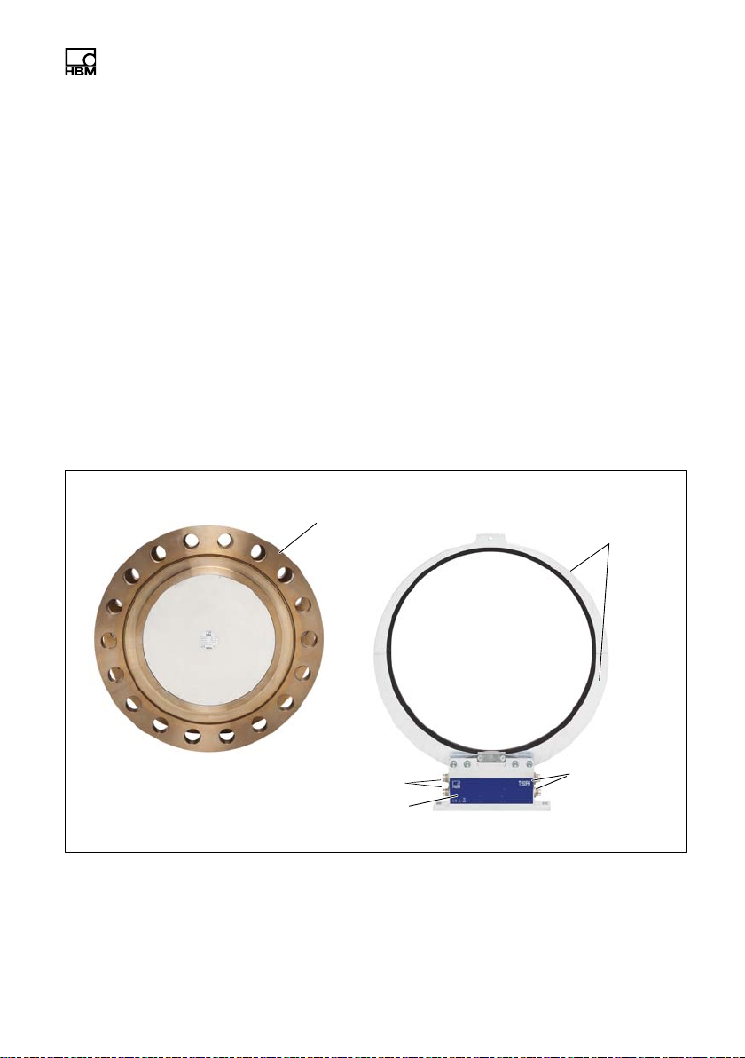
4 Structure and mode of operation
The torque flange consist of two separate parts: the rotor and the stator. The
rotor comprises the measuring body and the signal transmission elements.
Strain gages (SGs) are installed on the measuring body. The rotor electronics
for transmitting the bridge excitation voltage and the measurement signal are
located centrally in the flange. The transmitter coils for contactless transmission
of excitation voltage and measurement signal are located on the measuring
body's outer circumference. The signals are sent and received by a separable
antenna ring. The antenna ring is mounted on a housing that includes the elec
tronic system for voltage adaptation and signal conditioning.
Connector plugs for the torque and rotational speed signals, the voltage supply
and the digital output are located on the stator. The antenna segments (ring)
should be mounted concentrically around the rotor (see Chapter 5).
Rotor
Connector plugs
Stator housing
Type plate
Fig. 4.1 Mechanical construction
Antenna segments
Connector
plugs
T40FH A4429-3.0 HBM: public 13
Page 16

Structure and mode of operation
The rotational speed sensor is mounted on the stator in Option 5 with a rota
tional speed measuring system. Rotational speed is measured magnetically by
a magnetic field dependent resistor and a ring gear attached to the rotor.
14 A4429-3.0 HBM: public T40FH
Page 17

Mechanical installation
5 Mechanical installation
5.1 Important precautions during installation
Notice
A torque flange is a precision measurement element and therefore needs care
ful handling. Dropping or knocking the transducer may cause permanent dam
age. Make sure that the transducer cannot be overloaded, including while it is
being mounted.
S Handle the transducer with care.
S Check the effect of bending moments, critical rotational speeds and natural
torsional vibrations, to prevent the transducer being overloaded by reso
nance sharpness.
S Make sure that the transducer cannot be overloaded.
WARNING
There is a danger of the transducer breaking if it is overloaded. This can cause
danger for the operating personnel of the system in which the transducer is
installed.
Implement appropriate safety measures to avoid overloads and to protect
against resulting dangers.
S Use a threadlocker (medium strength, e.g. LOCTITE) to glue the screws into
the counter thread to exclude prestressing loss due to screw slackening, in
the event of alternating loads.
S Comply with the mounting dimensions to enable correct operation.
An appropriate shaft flange enables the T40FH torque flange to be mounted
directly. It is also possible to mount a joint shaft or relevant compensating ele
ment directly on the rotor (using an intermediate flange when required). Under
T40FH A4429-3.0 HBM: public 15
Page 18

Mechanical installation
no circumstances should the permissible limits specified for bending moments,
lateral and longitudinal forces be exceeded. Due to the T40FH torque flange's
high torsional stiffness, dynamic shaft train changes are kept to a minimum.
Important
Even if the unit is installed correctly, the zero point adjustment made at the fac
tory can shift by up to approx. 0.5% of the characteristic value. If this value is
exceeded, we advise you to check the mounting conditions. If the residual zero
drift when the unit is removed is greater than 1% of the characteristic value,
please send the transducer back to the Darmstadt factory for testing.
5.2 Conditions on site
The T40FH torque flange must be protected against coarse dirt particles, dust,
oil, solvents and moisture.
There is wide ranging compensation for the effects of temperature on the out
put and zero signals of the transducer (see Chapter 15 “Specifications"). If
there are no static temperature ratios, for example, because of the temperature
differences between the measuring body and the flange, the values given in the
specifications can be exceeded. In this case, ensure static temperature ratios
by cooling or heating, depending on the application. As an alternative, check if
thermal decoupling is possible, e.g. by means of heat radiating elements such
as multiple-disc couplings.
5.3 Mounting position
The torque flange can be mounted in any position.
With clockwise torque, the output frequency for Option 5, code DU2 is 60 … 90
kHz (Option 5, Code SU2: 10 … 15kHz; Option HU2: 240 … 360kHz). In con
junction with HBM amplifiers or when using the voltage output, a positive output
signal (0 V …+10 V) is present. In the case of the rotational speed measuring
system, an arrow is attached to the stator housing to clearly identify the direc
tion of rotation: If the measurement flange moves in the direction of the arrow,
connected HBM measuring amplifiers deliver a positive output signal.
16 A4429-3.0 HBM: public T40FH
Page 19

Mechanical installation
With the non-rotating version, there is a positive output signal in mV/V for clock
wise torque.
5.4 Installation options
As its diameter is less than the flange diameter of the rotor, the antenna ring
must be dismantled for mounting. If access to the rotor in its installed state is
difficult, we recommend mounting the antenna ring beforehand. It is essential in
this case to comply with the notes on assembling the antenna segments (see
Section 5.7).
T40FH A4429-3.0 HBM: public 17
Page 20
Mechanical installation
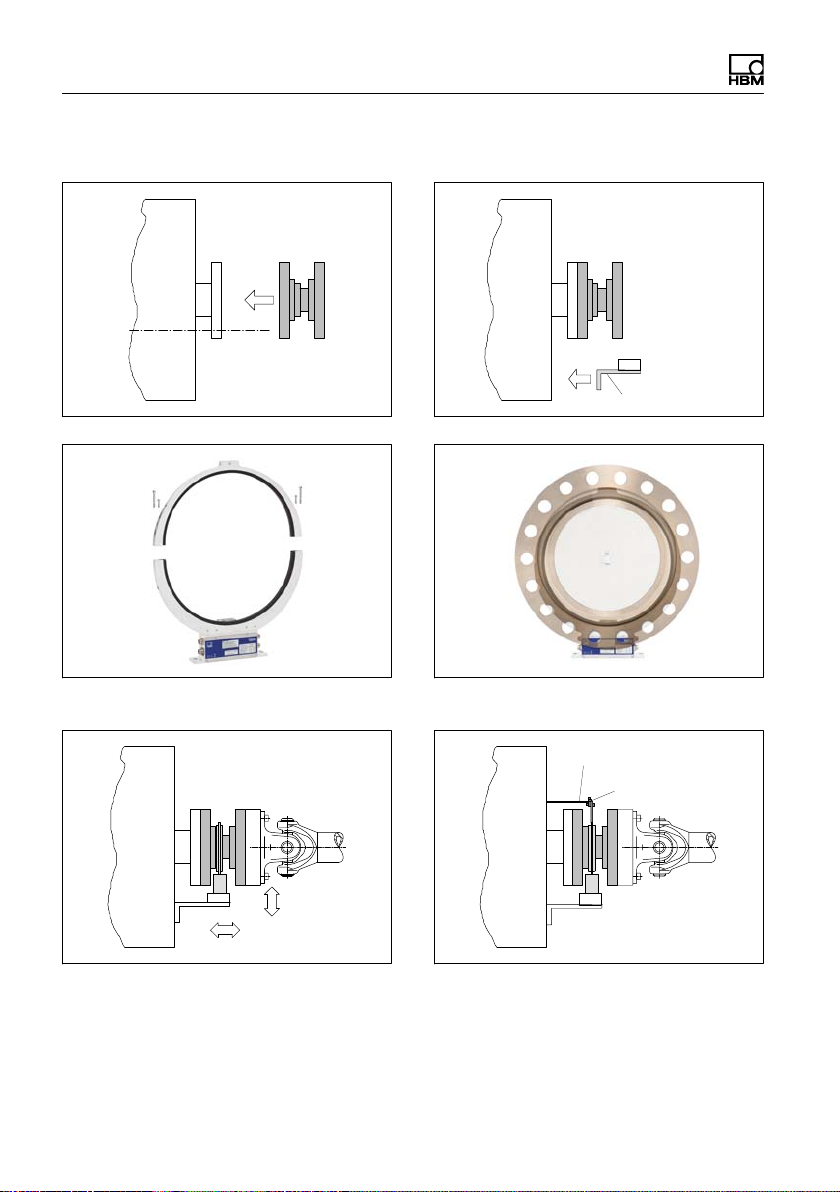
5.4.1 Installation with antenna ring removed
1 Install the rotor
2 Fit the stator mounting
Customer
mounting
3 Remove one antenna segment
5 Align and fully assemble the stator
4 Fit the antenna segment around the shaft
train
Support supplied by customer
Clamp fixture
6 Fit the clamp fixture
18 A4429-3.0 HBM: public T40FH
Page 21
Mechanical installation
5.5 Preparing for the rotor mounting
CAUTION
The rotor is heavy (as much as 142 kg, depending on the measuring range)!
Use a crane or other suitable lifting equipment to lift it out of its packaging and
install it.
When working with the crane, be sure to meet relevant safety requirements
and wear safety boots.
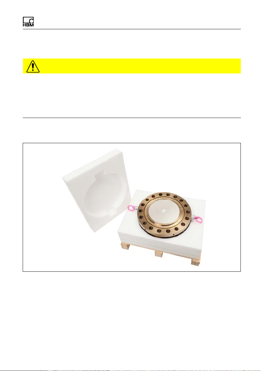
1. Remove the top layer of foam packaging.
Fig. 5.1 T40FH packaging
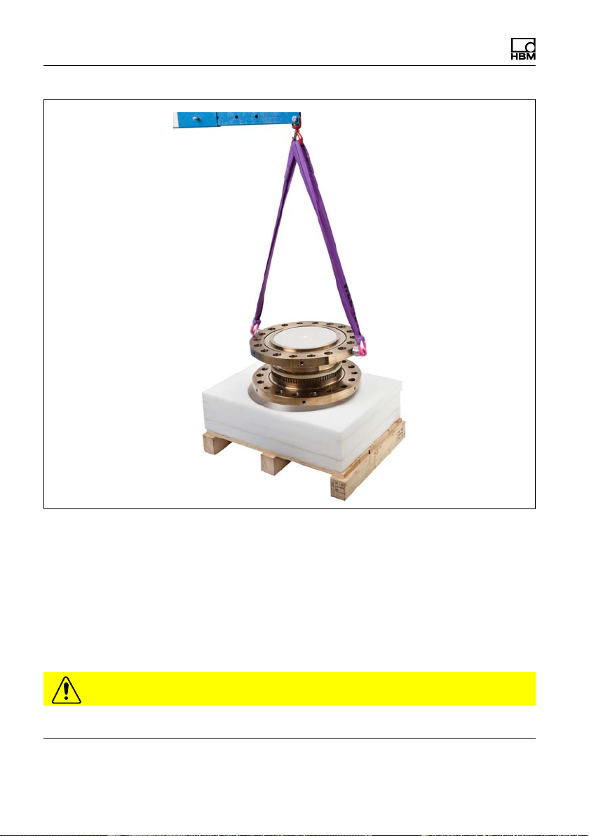
2. Fasten two equal-length ropes with sufficient load-carrying capacity to the
eyebolts (each of the two ropes must be able to bear the full weight of the
rotor) and hoist the rotor out of its packaging with the crane (see Fig. 5.2).
T40FH A4429-3.0 HBM: public 19
Page 22
Mechanical installation
Fig. 5.2 Hoisting the rotor out of its packaging
3. Place the rotor on a clean and stable base.
4. Remove one of the eyebolts.
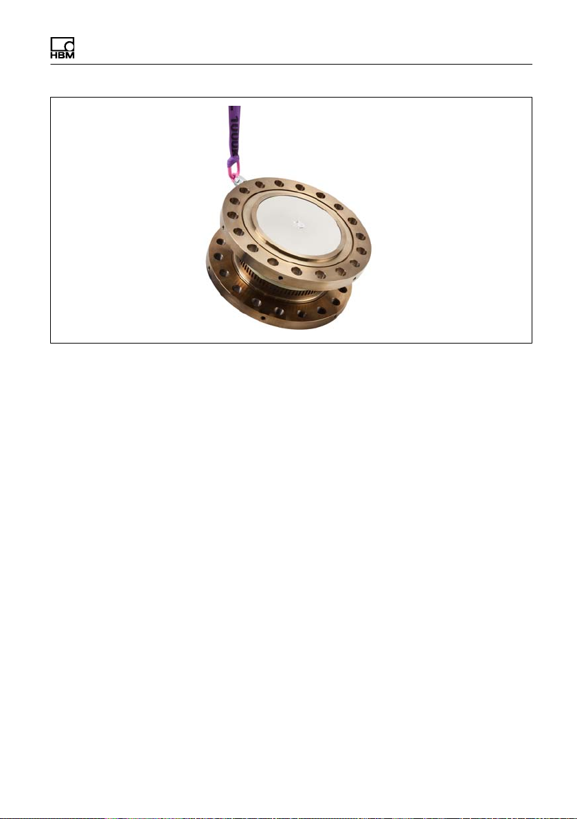
5. Carefully lift the rotor until it hangs free.
6. Carefully tilt the rotor by lowering it over the flange edge until it rests hori
zontally on both outer flange surfaces (see Fig. 5.3).
CAUTION
Crush hazard. Keep your hands and feet a safe distance away from the rotor.
20 A4429-3.0 HBM: public T40FH
Page 23
Mechanical installation
Fig. 5.3 Tilting the rotor
7. Secure the rotor with wedges to stop it from rolling away.
8. Screw the second eyebolt back into the tapped holes in the outer flange sur
face.
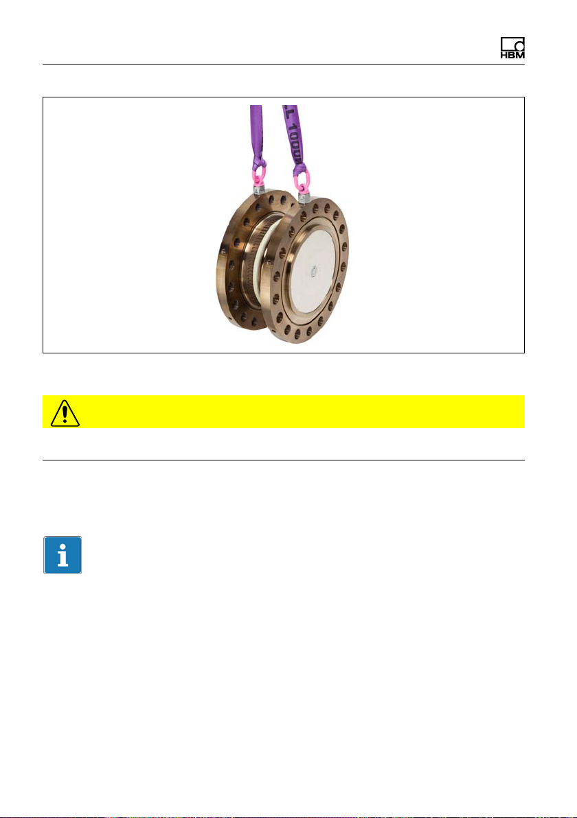
9. Fasten the rotor to the hook of the crane with two equal-length ropes. The
rotor is now prepared for horizontal installation (see Fig. 5.4).
T40FH A4429-3.0 HBM: public 21
Page 24
Mechanical installation
Fig. 5.4 Fastening for horizontal installation
CAUTION
You must remove the eyebolts after mounting! Keep them safe for later use.
5.6 Mounting the rotor
Tip
Usually the rotor type plate is no longer visible after installation. This is why we
include with the rotor additional stickers with the important characteristics,
which you can attach to the stator or any other relevant test-bench compo
nents. You can then refer to them whenever there is anything you wish to
know, such as the shunt signal. To explicitly assign the data, the identification
number and the size are engraved on the rotor flange, where they can be seen
from outside.
22 A4429-3.0 HBM: public T40FH
Page 25
Mechanical installation
Notice
Make sure during installation that you do not damage the measuring zone
marked in Fig. 5.5 by using it to support tools or knocking tools against it when
tightening screws, for example. This can damage the transducer and produce
measurement errors, or even destroy the transducer.
1. Prior to installation, clean the plane faces of the transducer flange and the
counter flange.
For safe torque transfer, the surfaces must be clean and free from grease.
Use a piece of cloth or paper soaked in solvent. When cleaning, make sure
that you do not damage the transmitter winding.
Hexagon screw DIN 933
Measuring zone
Hexagon screw DIN 933
Fig. 5.5 Bolted rotor connection
2. For connection of the flange, (see Fig. 5.5) use hexagon screws DIN 933 of
a suitable length (dependent on the connection geometry, see Tab. 5.1 on
Page 24).
3. Fasten all screws with the specified torque (Tab. 5.1 on Page 24).
T40FH A4429-3.0 HBM: public 23
Page 26

Mechanical installation
4. Now remove the ring bolts and mounting ring(s).
Important
Keep them in a safe place for future dismounting.
Important
Use a threadlocker (medium strength, e.g. LOCTITE) to glue the screws into
the counter thread to exclude prestressing loss due to screw slackening, in the
event of alternating loads.
Notice
Comply with the maximum thread reach as per Tab. 5.1, Page 24. Otherwise
significant measurement errors may result from a torque shunt, or the trans
ducer may be damaged.
Measure
ment
range
kNVm Z
100
150
150
200
250
300
1)
DIN 933; black/oiled/m
Tab. 5.1 Fastening screws
Fastening screws
1)
M30
M36 18 4250
Property class NVm
12.9
=0.125
tot
Number of
screws per
flange
16 2450
Prescribed
tightening moment
24 A4429-3.0 HBM: public T40FH
Page 27
Mechanical installation
Important
Dry screw connections can result in different and higher friction factors (see
VDI 2230, for example). This means a change to the required tightening
torques.
The required tightening torques can also change if you use screws with a sur
face or property class other than that specified in Tab. 5.1, as this affects the
coefficient of friction.
5.7 Installing the stator
On delivery, the stator has already been installed and is ready for operation.
The upper antenna segment can be separated from the stator, for example, for
maintenance or to facilitate stator installation.
Ø 6.5 mm hole for fixing
the antenna segment
Antenna segment
screws with washers
(M4+M5)
Antenna segment
screws with washers
(M4+M5)
upper
Antenna segments
lower
Stator housing
Fig. 5.6 Bolted connection of the antenna segments on the stator
1. Undo and remove both the bolted connections (M4+M5) on the upper
antenna segment.
T40FH A4429-3.0 HBM: public 25
Page 28

Mechanical installation
There are fan-type lock washers (M4+M5) between the antenna segments:
make sure that they do not get lost.
2. Use an appropriate mounting base to install the stator housing in the shaft
train, so that there is sufficient opportunity for horizontal and vertical adjust
ments. Do not fully tighten the screws yet.
3. Now use four hexagon socket screws to mount the upper antenna segment
removed in Point 1. on the lower antenna segment.
Make sure that the fan-type lock washers are inserted between the antenna
segments (these ensure that there is a defined contact resistance)!
Important
To guarantee that they function perfectly, the fan-type lock washers (A5, 3-FST
DIN 6798 ZN/galvanized) must be replaced after the bolted antenna connection
has been loosened three times.
4. Now tighten all the bolted antenna segment connections with a tightening
torque of 5 N⋅m.
5. Then align the antenna to the rotor in such a way that the antenna encloses
the rotor more or less coaxially and the antenna wire in the axial direction
has the same position as the center of the transmitter winding on the rotor.
To make alignment easier, the outer edge of the stator antenna segment
and the outer edge of the stator winding carrier should be on the same line
(in alignment). Conform to the permissible alignment tolerances stated in
the specifications.
6. Now fully tighten the bolted stator housing connection.
Prevention of axial stator oscillation
Depending on the operating conditions, stator oscillation may be induced. This
effect is dependent on:
S the rotational speed,
S the antenna diameter (depends in turn on the measuring range),
S the construction of the machine base.
26 A4429-3.0 HBM: public T40FH
Page 29
Mechanical installation
Important
To avoid axial oscillation, a clamp fixture is enclosed with the torque transducer
to enable the antenna ring to be supported. There is a hole, 6.5 mm in diame
ter, on the upper antenna segment to receive the clamping device (see
Fig. 5.7).
The cable plug (not included in the scope of supply) also requires support in
this case; a construction example is shown in Fig. 5.9.
Fig. 5.7 Construction example for supporting the antenna ring
7. Fasten the clamp fixture with the enclosed bolted connection, as shown in
Fig. 5.8. Clamp a suitable support element (we recommend a Ø 3-6 mm
threaded rod) between the upper and lower parts of the clamp fixture and
tighten the clamping screws.
T40FH A4429-3.0 HBM: public 27
Page 30
Mechanical installation
Support supplied by customer
Fig. 5.8 Supporting the antenna ring
Clamp fixture
Antenna ring
Fig. 5.9 Construction example for plug clamps (for two plugs)
28 A4429-3.0 HBM: public T40FH
Page 31

Mechanical installation
5.8 Rotational speed measuring system
The rotor is delivered as standard with a ring gear for the rotational speed mea
suring system. The option is available to fit the stator with a sensor head to
scan the mechanical increments (ring gear).
Ring gear
Sensor head for
measuring rotational
speed (optional)
Fig. 5.10 Torque transducer with rotational speed measurement (optional)
Important
The rotational speed measuring system uses a magnetic measuring principle.
In applications where high magnetic field strengths can occur, e.g. eddy-current
brakes, implement suitable measures to ensure that the maximum permissible
magnetic field strength cannot be exceeded (see Chapter 15 "Specifications",
Page 60).
Stator alignment (rotational speed measuring system)
For measuring mode to operate perfectly, the speed sensor must be placed at
a defined position to the rotor ring gear. When the radial and axial alignment of
T40FH A4429-3.0 HBM: public 29
Page 32

Mechanical installation
the stator is accurate for torque measurement, the alignment of the rotational
speed measuring system is also correct.
Axial alignment:
At the factory, the sensor head of the rotational speed measuring system must
be adjusted so that when the axial alignment of the stator is exact (antenna ring
positioned precisely above the rotor winding carrier), the sensor is in the cor
rect position to the rotor ring gear.
Ring gear
Axial alignment
Radial
distance
Speed sensor
Fig. 5.11 Side view
Radial alignment:
The rotor axis and the axis of the speed sensor must be along a line at right
angles to the stator platform. The nominal radial distance is crucial for radial
alignment (see Fig. 5.11). The optimum distance is 2.5 mm and is achieved
when the rotor and the stator are in precise radial alignment.
30 A4429-3.0 HBM: public T40FH
Page 33

Electrical connection
6 Electrical connection
6.1 General information
S With extension cables, make sure that there is a proper connection with
minimum contact resistance and good insulation.
S All plug connections or swivel nuts must be fully tightened.
Important
Transducer connection cables from HBM with attached connectors are marked
in accordance with their intended purpose (Md or n). When cables are short
ened, inserted into cable ducts or installed in control cabinets, this marking can
be lost or hidden. So the cables must be marked beforehand, just in case.
6.2 EMC protection
Important
Transducers are EMC-tested in accordance with EC directives and identified by
CE certification. However, you must connect the shield of the connection cable
on the shielding electronics enclosure in order to achieve EMC protection for
the measuring chain.
Special electronic coding methods are used to protect the purely digital signal
transmission between the transmitter head and the rotor from electromagnetic
interference.
The cable shield is connected with the transducer housing. This encloses the
measurement system (without the rotor) in a Faraday cage when the shield is
laid flat at both ends of the cable. With other connection techniques, an EMCproof shield should be applied in the wire area and this shielding should also be
laid flat (also see HBM Greenline Information, brochure i1577).
T40FH A4429-3.0 HBM: public 31
Page 34

Electrical connection
Electrical and magnetic fields often induce interference voltages in the measur
ing circuit. Therefore:
S Use shielded, low-capacitance measurement cables only (HBM cables fulfill
both conditions).
S Only use plugs that meet EMC guidelines.
S Do not route the measurement cables parallel to power lines and control
circuits. If this is not possible, protect the measurement cable witha steel
conduit, for example.
S Avoid stray fields from transformers, motors and contact switches.
S Do not ground the transducer, amplifier and indicator more than once.
S Connect all the devices in the measuring chain to the same protective con
ductor.
S In the case of interference due to potential differences (compensating cur
rents), supply voltage zero and housing ground must be disconnected on
the amplifier and a potential equalization line established between the stator
housing and the amplifier housing (copper conductor, minimum 10 mm
wire crosssection).
S Should differences in potential occur between the machine rotor and stator
because of unchecked leakage, for example, this can usually be overcome
by connecting the rotor definitively to ground, e.g. with a wire loop. The sta
tor must be connected to the same (ground) potential.
2
6.3 Connector pin assignment Option 4, Code SU2, DU2, HU2
The stator housing has two 7-pin connectors, an 8-pin connector and a 16-pin
connector.
The supply voltage and shunt signal connections of connectors 1 and 3 are
each electrically interconnected, but are protected against compensating cur
rents by diodes. There is also a self-resetting fuse (multifuse) to protect the
supply voltage connections against overload by the stator.
32 A4429-3.0 HBM: public T40FH
Page 35

Electrical connection
Assignment for connector 1 - supply voltage and frequency output signal
61
Device plug
5
72
3
4
Top view
KAB153 KAB149 KAB178
Con
nector
pin
Assignment Color
Torque measurement signal
1
(frequency output; 5 V
Supply voltage 0 V
2
2,3
)
D‐SUB
code
connec
connector
tor pin
wh 13 5
bk 5 -
3 Supply voltage 18 V … 30 V bu 6 -
Torque measurement signal
4
(frequency output; 5 V
Measurement signal 0 V; symmet
5
rical
2,3
)
rd 12 10
gy 8 6
6 Shunt signal trigger 5 V … 30 V gn 14 15
Shunt signal 0 V
7
gy 8
Shield connected to housing ground
1)
Bridge between 4 + 9
2)
RS-422 complementary signals; with cable lengths exceeding 10 m, we recommend using a
termination resistor R = 120 ohms between the (wh) and (rd) wires.
3)
RS‐422: Pin 1 corresponds to A, Pin 4 corresponds to B.
1)
HD‐SUB
pin
T40FH A4429-3.0 HBM: public 33
Page 36

Electrical connection
Notice
Torque flanges are only intended for operation with a DC supply voltage. They
must not be connected to older HBM amplifiers with square-wave excitation.
This could destroy the connection board resistors or cause other faults in the
amplifiers.
Assignment for connector 2 - rotational speed measuring system
2
5
3
4
Device plug
8
1
Top view
6
7
1)
pin
Con
nector
pin
1
KAB154 KAB150 KAB179
Assignment Color
code
Speed measurement signal
(pulse string, 5V; 0°)
2)
rd 12 10
D-SUB
connector
pin
HD-SUB
connector
2 Not in use bu - -
Speed measurement signal
(pulse string, 5 V; 90° phase
3
2
gy 15 8
shifted)
4 Not in use bk - 5 Not in use vt - -
2)
Speed measurement signal
6
(pulse string, 5V; 0°)
wh 13 5
Speed measurement signal
2
7
(pulse string, 5 V; 90° phase
gn 14 7
shifted)
34 A4429-3.0 HBM: public T40FH
Page 37

Electrical connection
AssignmentCon
nector
pin
8 Supply voltage zero bk/bu
Color
code
3)
D-SUB
connector
pin
8 6
HD-SUB
connector
Shield connected to housing
ground
1)
Bridge between 4 + 9
2)
RS-422 complementary signals; with cable lengths exceeding 10 m, we recommend using a
termination resistor of R = 120 ohms.
3)
For KAB163 / KAB164 color code brown (bn)
Pin 1
Pin 6
Pin 3
Pin 7
pin
Fig. 6.1 Speed signals at connector 2 (rotational speed in the direction of the arrow)
T40FH A4429-3.0 HBM: public 35
Page 38

Electrical connection
Pin 1
Pin 6
Pin 3
Pin 7
Fig. 6.2 Speed signals at connector 2 (rotational speed against the direction of the
arrow)
Assignment for connector 3 - supply voltage and frequency output signal
Device plug
61
5
72
3
4
Top view
Con
nector
pin
Assignment Color
code
Torque measurement signal
1
(voltage output; ±10 V)
2 Supply voltage 0 V; bk
3 Supply voltage 18 V … 30 V bu
Torque measurement signal (voltage
4
output; ±10 V)
5 Not in use gy
6 Shunt signal trigger 5 V … 30 V gn
Shunt signal 0 V;
7
Shield connected to housing ground
wh
rd
gy
36 A4429-3.0 HBM: public T40FH
Page 39

Electrical connection
Assignment for connector 4
TMC - only for connection to the Torque Interface Modules of the TIM family
within HBM.
6.4 Connector pin assignment Option 3, Code PNJ
Binder 723
61
72
5
3
4
Top view
Con
nector
pin
Assignment Color
code
1 Measurement signal (+) UA wh
2 Bridge excitation voltage (-) UB and
TEDS
3 Bridge excitation voltage (+) UB bu
4 Measurement signal (-) UA rd
5 Not in use 6
Sense lead (+)
7
Sense lead (-) and TEDS
Shield connected to housing ground
bk
gn
gy
6.5 Supply voltage (SU2, DU2, HU2)
The transducer must be operated with a safety extra-low voltage (nominal
(rated) supply voltage 18 … 30 V
flanges within a test bench. Should the device be operated on a DC voltage
1)
network
, additional precautions must be taken to discharge excess voltages.
The information in this Chapter relates to the standalone operation of the
T40FH without HBM system solutions.
. You can supply one or more torque
DC)
The supply voltage is electrically isolated from the signal outputs and shunt sig
nal inputs. Connect a safety extra-low voltage of 18 V … 30 V to pin 3 (+) and
pin 2 (
1)
) of connectors 1 or 3. We recommend that you use HBM cable KAB
Distribution system for electrical energy with greater physical expansion (over several test
benches, for example) that may possibly also supply consumers with high nominal (rated)
currents.
T40FH A4429-3.0 HBM: public 37
Page 40

Electrical connection
8/00 -2/2/2 and appropriate sockets (see accessories, Page 58). The cable can
be up to 50 m long for voltages ≥24 V, otherwise it can be up to 20 m long.
If the permissible cable length is exceeded, you can feed the supply voltage in
parallel over two connection cables (connectors 1 and 3). This enables you to
double the permissible length. Alternatively, install an on-site power supply.
Important
The instant you switch on, a current of up to 4 A may flow and this can switch
off power packs with electronic current limiters.
6.6 Supply voltage (Option 3, Code PNJ)
A pre-wired 6-wire transducer connection cable with free ends is available as
an accessory.
Extension cables should be shielded and low capacitance. HBM provides spe
cific cables for this purpose, the 1-KAB0304A-10 (pre-wired) and the
KAB8/00-2/2/2 (by the meter).
The pin assignment can be found in the table in section 6.4.
For the pin assignments at the amplifier end, please refer to the relevant ampli
fier documentation.
38 A4429-3.0 HBM: public T40FH
Page 41

TEDS transducer identification
7 TEDS transducer identification
(Option 3, Code PNJ)
TEDS stands for "Transducer Electronic Data Sheet". An electronic data sheet
can be stored in the transducer as defined in the IEEE1451.4 standard, making
it possible for the amplifier to be set up automatically. A suitably equipped
amplifier reads out the transducer characteristics (electronic data sheet), trans
lates them into its own settings and measurement can then start.
The digital identification system is available at plug connection PIN 7 to PIN 2.
The HBM TEDS Editor is used to store the data. This is a component of the
HBM "MGCplus Setup Assistant" software. You can use the Editor to manage
different user rights, thus protecting the essential transducer data from being
overwritten by mistake.
7.1 Hierarchy of user rights
7.1.1 Standard rights (USR level)
This level concerns rights which the user of the transducer needs in order to
change the entries which depend on the conditions of use.
7.1.2 Calibration rights (CAL level)
This level concerns rights which are needed by a calibration laboratory, for
instance, if the sensitivity in the TEDS memory needs to be changed.
7.1.3 Administrator rights (ID level)
Administrator rights in relation to TEDS are intended for the sensor manufac
turer.
Different user rights are needed in order to amend the various entries in the
templates, and these rights may differ from one entry to the next within a tem
plate.
T40FH A4429-3.0 HBM: public 39
Page 42

TEDS transducer identification
7.2 Contents of the TEDS memory as defined in IEEE 1451.4
The information in the TEDS memory is organized into areas, which are pre
structured to store defined groups of data in table form.
Only the entered values are stored in the TEDS memory itself. The amplifier
firmware assigns the interpretation of the respective numerical values. This
places a very low demand on the TEDS memory. The memory content is
divided into three areas:
Area 1
An internationally unique TEDS identification number (cannot be changed).
Area 2
The base area (basic TEDS), to the configuration defined in standard IEEE
1451.4. The transducer type, the manufacturer and the transducer serial num
ber are contained here.
Example:
TEDS content with the identity number for the T40FH/150 kN@m sensor with
serial no. 123456, made in November 2005
TEDS transducer identification
Manufacturer HBM
Model T40FH
Version letter
Version number
Serial number 123456
Area 3
Data specified by the manufacturer and the user are contained in this area.
For the T40FH torque flange, HBM has already described the Bridge Sensor
and Channel name templates.
40 A4429-3.0 HBM: public T40FH
Page 43

TEDS transducer identification
Additional templates, such as the Signal Conditioning template, can also be
described by the user.
Template: Bridge Sensor
1
Parameter Value
Transducer Elec
trical Signal Type
Minimum Torque 0.000 N@m CAL The physical measurand
Maximum Torque 150000 N@m CAL
Minimum Electri
cal
Value
Maximum Electri
cal Value
Mapping Method Linear This entry cannot be
Bridge type Full ID The bridge type. "Full" for
Impedance of
each bridge ele
ment
Response time 1.0000000u s ID Of no significance to
Excitation Level
(Nominal)
)
Bridge
Sensor
0.0000m V/V CAL The difference between
1.8245m V/V CAL
1550+-100 ohm ID Input resistance accord
5.0 V ID Nominal (rated) excita
Unit Required
user
rights
ID
Explanation
and unit are defined
when the template is cre
ated, after which they
cannot be changed.
these values is the sensi
tivity according to the
HBM manufacturing cer
tificate or from the cali
bration.
changed
a full bridge.
ing to the HBM data
sheet
HBM transducers
tion voltage according to
the HBM data sheet
T40FH A4429-3.0 HBM: public 41
Page 44

TEDS transducer identification
Template: Bridge Sensor
1
Parameter
)
UnitValue
user
rights
Excitation Level
2.5 V ID Lower limit for the oper
(Minimum)
Excitation Level
12.0 V ID Upper limit for the oper
(Maximum)
Calibration Date 1-Nov-2005 CAL Date of the last calibra
Calibration Initials HBM CAL Initials of the calibrator or
ExplanationRequired
ating range of the excita
tion voltage according to
the HBM data sheet.
ating range of the excita
tion voltage according to
the HBM data sheet.
tion or creation of the test
certificate (if no calibra
tion carried out), or of the
storage of the TEDS data
(if only nominal (rated)
values from the data
sheet were used).
Format: day-month-year.
Abbreviations for the
months: Jan, Feb, Mar,
Apr, May, Jun, Jul, Aug,
Sep, Oct, Nov, Dec.
calibration laboratory
concerned.
42 A4429-3.0 HBM: public T40FH
Page 45

TEDS transducer identification
Template: Bridge Sensor
1
Parameter
Calibration Period
(Days)
Measurement
location ID
1)
Typical values for an HBM T40FH/150 kN@m torque flange
Template: HBM Channel Name
Channel name T40FH/150 kNm
)
730 days CAL Time before recalibra
0 USR Identification number for
UnitValue
user
rights
ExplanationRequired
tion, calculated from the
date specified under Cal
ibration Date.
the measuring point.
Can be assigned accord
ing to the application.
Possible values: a num
ber from 0 to 2047. If this
is not enough, the HBM
Channel Comment tem
plate can also be used
for this purpose.
When creating the Bridge Sensor template, the manufacturer defines the physi
cal measured quantity and the physical unit.
The available unit for the particular measured quantity is specified in the IEEE
Standard. For the measured quantity of torque, the unit is "N@m".
At the time of creating the template it is also necessary to choose between the
options "Full Precision", "mV/V" and "uV/V" for the accuracy of the characteris
tic transducer curve mapped in TEDS.
The factory setting is "Full Precision", in order to be able to use full digital reso
lution. This choice is also recommended to users who program the TEDS mem
ory themselves.
T40FH A4429-3.0 HBM: public 43
Page 46

Shunt signal
8 Shunt signal
The T40FH torque flange delivers an electrical shunt signal that can be acti
vated from the amplifier for measuring chains with HBM components. The
transducer generates a shunt signal of about 50% of the nominal (rated)
torque; the precise value is specified on the type plate. After activation, adjust
the amplifier output signal to the shunt signal supplied by the connected trans
ducer, to adapt the amplifier to the transducer.
Information
The transducer should not be under load when the shunt signal is being mea
sured, as the shunt signal is mixed additively.
Triggering the shunt signal
Applying a safety extra-low voltage of 5 … 30 V to pins 6 (+) and 7 (
nector 1 or 3, triggers the shunt signal.
The nominal (rated) voltage for triggering the shunt signal is 5V (triggering at U
> 2.5V), but when voltages are less than 0.7V, the transducer is in measuring
mode. The maximum permissible voltage is 30V, current consumption at nomi
nal (rated) voltage is approx. 2 mA and at maximum voltage, approx. 18 mA.
The trigger voltage for the shunt signal is electrically isolated from the supply
voltage and the measuring voltage.
Tip
The shunt signal can be triggered by the amplifier or via the operating software
in HBM system solutions.
44 A4429-3.0 HBM: public T40FH
) at con
Page 47

Functionality testing
9 Functionality testing
You can check the functionality of the rotor and the stator from the LEDs on the
stator.
LED A, rotor status
LED B, stator status
Fig. 9.1 LEDs on the stator housing
Important
Once the supply voltage is applied, the torque transducer needs up to a further
4 seconds to be ready for operation.
9.1 Rotor status, LED A (upper LED)
Color Significance
Green (pulsating) Internal rotor voltage values o.k.
Flashing orange Rotor and stator mismatched (an increasing flashing fre
quency indicates the degree of misalignment)
=> Correct the rotor/stator alignment.
T40FH A4429-3.0 HBM: public 45
Page 48

Functionality testing
SignificanceColor
Pulsating orange Rotor status cannot be defined
=> Correct the rotor/stator alignment.
If the LED still pulsates orange, it is possible that there is a
hardware defect. The measurement signals reflect the level of
the fault.
Red (pulsating) Rotor voltage values not o.k.
=> Correct the rotor/stator alignment.
If the LED still pulsates red, it is possible that there is a hard
ware defect. The measurement signals reflect the level of the
fault.
Pulsating means that the LED goes dark for about 20 ms every second (sign of
life), making it possible to detect that the transducer is functioning.
9.2 Stator status, LED B (lower LED)
Color Significance
Green
(permanently lit)
Green, intermittently
orange.
Numerous synchro
nization errors:
Measurement signal transmission and internal stator voltages
o.k.
Orange if y5 measured values in succession are transmitted
incorrectly, until the end of incorrect transmission. The mea
surement signals reflect the level of the fault for the duration
of the transmission error + for approx. another 3.3 ms.
permanently orange
Orange
(permanently lit)
Permanently disrupted transmission, the measurement sig
nals reflect the level of the fault. (f
= 0 Hz, U
out
= defect
out
level).
=> Correct the rotor/stator alignment.
Red
(permanently lit)
Internal stator defect, the measurement signals reflect the
level of the fault (f
= 0 Hz, U
out
= defect level).
out
46 A4429-3.0 HBM: public T40FH
Page 49

Load-carrying capacity
10 Load-carrying capacity
Nominal (rated) torque can be exceeded statically up to the torque limit. If the
nominal torque is exceeded, additional irregular loading is not permissible. This
includes longitudinal forces, lateral forces and bending moments. Limit values
can be found in Chapter "" on Page 60.
Measuring dynamic torque
The torque flange can be used to measure static and dynamic torques. The
following apply to the measurement of dynamic torque:
S The T40FH calibration performed for static measurements is also valid for
dynamic torque measurements.
S The natural frequency f
depends on the moments of inertia J
of the mechanical measuring arrangement
0
and J2 of the connected rotating
1
masses and the torsional stiffness of the T40FH.
Use the equation below to approximately determine the natural frequency f
of
0
the mechanical measuring arrangement:
f
= natural frequency in Hz
f0+
1
· cT·
2p
Ǹ
ǒ
J
)
1
Ǔ
J
2
1
1
0
J
J2= mass moment of inertia in kg⋅m
1,
c
= torsional stiffness in N⋅m/rad
T
2
S The permissible mechanical vibration bandwidth (peak-to-peak) can also be
found in the specifications.
T40FH A4429-3.0 HBM: public 47
Page 50

Maintenance
Nominal (rated) torque M
+ M
nom
0
- M
nom
as a %
nom
Oscillation bandwidth
Oscillation bandwidth
Fig. 10.1 Permissible dynamic loading
11 Maintenance
T40FH torque flanges are maintenance free.
200% oscillation
Time t
Oscillation bandwidth
bandwidth
48 A4429-3.0 HBM: public T40FH
Page 51

Waste disposal and environmental protection
12 Waste disposal and environmental protection
All electrical and electronic products must be disposed of as hazardous waste.
The correct disposal of old equipment prevents ecological damage and health
hazards.
Statutory waste disposal mark
The electrical and electronic devices that bear this sym
bol are subject to the European waste electrical and elec
tronic equipment directive 2002/96/EC. The symbol indi
cates that, in accordance with national and local
environmental protection and material recovery and recy
cling regulations, old devices that can no longer be used
must be disposed of separately and not with normal
household garbage.
As waste disposal regulations may differ from country to country, we ask that
you contact your supplier to determine what type of disposal or recycling is
legally applicable in your country.
Packaging
The original packaging of HBM devices is made from recyclable material and
can be sent for recycling. Store the packaging for at least the duration of the
warranty. In the case of complaints, the torque flange must be returned in the
original packaging.
For ecological reasons, empty packaging should not be returned to us.
T40FH A4429-3.0 HBM: public 49
Page 52

Dimensions
13 Dimensions
13.1 T40FH torque transducer with rotational speed measuring system, Option 4, Code SU2, DU2, HU2
13.1.1 T40FH 100kNm - 150kNm
Dimensions in mm (1 mm = 0.03937)
Dimensions without tolerances, per
DIN ISO 2768-mk
518.5
61.5
Mounting
dimension
506.5
15
For axial
locking
Ø 6.5
A
A
16x22.5°=360°
152
210
9
22.5°
approx.
100
For connecting cable incl. plug
10
17
248
50 A4429-3.0 HBM: public T40FH
Page 53

Dimensions
Dimensions in mm (1 mm = 0.03937)
Dimensions without tolerances, per
DIN ISO 2768-mk
Height of
260.052
Ø450
Ø395
Ø260 H7 ()
95.5
rotational
speed sensor
184
(120)
32 32
12
M30
12
260.000
16
44
95
housing
Height of
89.5
432
53
27
Partial sections
cut A-A
Ø30.5
10
259.983
259.951
()
Ø260 g6
Ø282
Ø395
Ø450
T40FH A4429-3.0 HBM: public 51
Page 54

Dimensions
13.1.2 T40FH 200kNm - 300kNm
Dimensions in mm (1 mm = 0.03937)
Dimensions without tolerances, per
DIN ISO 2768-mk
15
85
Mounting
dimension
576.5
564.5
For axial
locking
Ø 6.5
190
A
22°
18x20°=360°
10
17
9
280
A
152
210
approx.
100
For connecting cable incl. plug
52 A4429-3.0 HBM: public T40FH
Page 55

Dimensions
Dimensions in mm (1 mm = 0.03937)
Dimensions without tolerances, per
DIN ISO 2768-mk
Ø540
speed
Height of
rotational
Ø470
2.5
102.5
sensor
M36
12
345.057
345.000
Ø345 H7 ()
95
40
housing
Height of
230
(150)
12
112
490
53
27
16
44
Partial sections
cut A-A
40
Ø37
10
344.982
344.946
()
Ø350
Ø540
Ø470
Ø345 g6
T40FH A4429-3.0 HBM: public 53
Page 56

Dimensions
13.2 T40FH torque transducer (non-rotating), Option 4, Code PNJ
13.2.1 T40FH 100 kNm - 150 kNm
Dimensions in mm (1 mm = 0.03937)
Dimensions without tolerances, per DIN ISO 2768-mk
22.5°
16x22.5°=360°
A
M30
(120)
32 32
184
76
10
B
259.983
259.951
()
Ø450
Ø260 g6
B
A
Ø395
Partial sections
cut A-A
12
260.052
260.000
Ø260 H7 ()
Ø450
54 A4429-3.0 HBM: public T40FH
Page 57

Dimensions in mm (1 mm = 0.03937)
Dimensions without tolerances, per DIN ISO 2768-mk
Min. bending
radius R=20
16x22.5°=360°
10.5°
75.5°
Ø18
Ø395
Partial sections
cut B-B
Dimensions
22.5°
Ø30.5
T40FH A4429-3.0 HBM: public 55
Page 58

Dimensions
13.2.2 T40FH 200kNm - 300kNm
Dimensions in mm (1 mm = 0.03937)
Dimensions without tolerances, per DIN ISO 2768-mk
20°
18x20°=360°
M36
A
A
Ø470
10
344.982
()
Ø540
Ø345 g6
40
344.946
Partial sections
(150)
B
B
cut A-A
230
99.4
40
12
345.057
345.000
Ø540
Ø345 H7 ()
56 A4429-3.0 HBM: public T40FH
Page 59

Dimensions
Dimensions in mm (1 mm = 0.03937)
Dimensions without tolerances, per DIN ISO 2768-mk
Min. bending
radius R=20
Partial sections
75.5°
Ø470
cut B-B
20°
18x20°=360°
0.5°
Ø18
Ø37
T40FH A4429-3.0 HBM: public 57
Page 60

Ordering numbers, accessories
14 Ordering numbers, accessories
Ordering number
K-T40FH [only with Option 2 = MF/ST]
Code Option 1: Measuring range to
100R 100 kN·m [only with Option 2 = MF/RO]
130R 130 kN·m [only with Option 2 = MF/RO]
150R 150 kN·m [only with Option 2 = MF/RO]
200R 200 kN·m [only with Option 2 = MF/RO]
250R 250 kN·m [only with Option 2 = MF/RO]
300R 300 kN·m [only with Option 2 = MF/RO]
Code Option 2: Components
MF Complete measurement flange
RO Rotor
ST Stator
N
Not rotating
Code Option 3: Accuracy
S Standard (linearity deviation including hysteresis ≤±0.1%)
Code Option 4: Electrical configuration [only with Option 2 = MF/ST]
SU2 Out. sign. 10 kHz ±5 kHz and ±10 V, Supp. volt. 18…30V DC
DU2 Out. sign. 60 kHz ±30 kHz and ±10 V, Supp. volt. 18…30V DC
HU2 Out. sign. 240 kHz ±120 kHz and ±10 V, Supp. volt. 18…30V DC
PNJ mV/V
Code Option 5: Rotational speed measuring system
0 Without rotational speed measuring system
1 Magnetic rotational speed measuring system
Code Option 6: Customized modification
S No customer modification
= PREFERRED TYPES
K-T40FH - 1 0 0 R - M F - S - D U 2 - 0 - S
58 A4429-3.0 HBM: public T40FH
Page 61

Ordering numbers, accessories
Accessories, to be ordered separately
Article Ordering
number
Connection cable for torque output; Option 2, Code MF (rotating)
Torque connection cable, 423 - D‐Sub 15P, 6m 1-KAB149-6
Torque connection cable, 423 - free ends, 6m 1-KAB153-6
Connection cable for torque output (mV/V), Option 2, Code N (non-rotating)
Connection cable for torque output, 423 - free ends, 6m 1-KAB139A-6
Connection cable for rotational speed output
Rotational speed connection cable, 423 - D-Sub 15P, 6m 1-KAB150-6
Rotational speed connection cable, 423 - free ends, 6m 1-KAB154-6
Rotational speed with reference signal connection cable, 423 8-pin -
D-Sub 15P, 6m
Rotational speed with reference signal connection cable, 423 8-pin -
free ends, 6m
TMC connection cable
TIM40/TMC connection cable, 6m 1-KAB174-6
Cable sockets
423G-7S, 7-pin (straight) 3-3101.0247
423W-7S, 7-pin (angle) 3-3312.0281
423G-8S, 8-pin (straight) 3-3312.0120
423W-8S, 8-pin (angle) 3-3312.0282
Connection cable, by the meter (min. order quantity: 10 m, price per meter)
Kab8/00-2/2/2 4-3301.0071
1-KAB163-6
1-KAB164-6
T40FH A4429-3.0 HBM: public 59
Page 62

Specifications
15 Specifications
Accuracy class 0.1
Torque measuring system (rotating)
Nominal (rated) torque M
nom
Nominal (rated) rotational speed rpm 3000 2000
Linearity deviation including
hysteresis,
related to nominal (rated) sensitivity
Frequency output
For a max. torque in the range:
between 0% of M
M
nom
> 20% of M
> 60% of M
nom
nom
and 20% of
nom
and 60% of M
and 100% of M
nom
nom
Voltage output
For a max. torque in the range:
between 0% of M
M
nom
> 20% of M
> 60% of M
nom
nom
and 20% of
nom
and 60% of M
and 100% of M
nom
nom
Rel. standard deviation of repeata
bility,
per DIN1319, related to the variation
of the output signal
Frequency output % ≤±0.02
Voltage output % ≤±0.02
Temperature effect per 10 K in the
nominal (rated) temperature range
on the output signal, related to the
actual value of the signal span
Frequency output % ≤±0.1
Voltage output % ≤±0.1
kNm 100 125 150 200 250 300
% ≤±0.03
% ≤±0.065
% ≤±0.1
% ≤±0.03
% ≤±0.065
% ≤±0.1
60 A4429-3.0 HBM: public T40FH
Page 63

Specifications
Nominal (rated) torque M
nom
on the zero signal, related to nominal
(rated) sensitivity
Frequency output % ≤±0.07
Voltage output % ≤±0.07
Nominal (rated) sensitivity
(spread between torque = zero and
nominal (rated) torque)
Frequency output 10kHz / 60kHz /
kHz 5/30/120
240kHz
Voltage output V 10
Sensitivity tolerance
(deviation of the actual output quantity
from the nominal (rated) sen
nom
at M
sitivity)
Frequency output % ±0.1
Voltage output % ±0.1
Output signal at torque = zero
Frequency output kHz 10/60/240
Voltage output V 0
Nominal (rated) output signal
Frequency output
1)
at positive nominal (rated) torque kHz 15
/ 90
2)
/ 360
(5 V balanced 4))
1)
at negative nominal (rated) torque kHz 5
/ 30
2)
/ 120
(5 V balanced 4))
Voltage output
at positive nominal (rated) torque V +10
at negative nominal (rated) torque V -10
Load resistance
Frequency output kΩ ≥2
Voltage output kΩ ≥10
300250200150125100kNm
3)
3)
T40FH A4429-3.0 HBM: public 61
Page 64

Specifications
Nominal (rated) torque M
nom
Longterm drift over 48h at refer
ence temperature
Frequency output % ≤±0.03
Voltage output % ≤±0.03
Measurement frequency range,
kHz 11) / 32) / 6
3)
-3 dB
Group delay μs t4001) / t2202) / t150
Residual ripple
Voltage output
Maximum modulation range
Frequency output kHz 2.5 … 17.5
5)
6)
mV t40
1)
/ 15 … 105
60 … 420
3)
Voltage output V -12 … +12
Energy supply
Nominal (rated) supply voltage (DC
V 18 … 30
safety extra low voltage)
Current consumption in measuring
A < 1
mode
Current consumption in startup mode A < 4 (typically 2) 50 μs
Nominal (rated) power consumption W < 10
Maximum cable length m 50
Shunt signal approx. 50 % of M
Tolerance of the shunt signal,
related to M
nom
% <±0.05
nom
Nominal (rated) trigger voltage V 5
Trigger voltage limit V 36
Shunt signal ON V min. >2.5
Shunt signal OFF V max. <0.7
Torque measuring system (non-rotating)
Accuracy class 0.1
300250200150125100kNm
3)
2)
/
62 A4429-3.0 HBM: public T40FH
Page 65

Specifications
Nominal (rated) torque M
Nominal (rated) sensitivity (nominal
(rated) signal range between torque =
zero and nominal (rated) torque)
Linearity deviation including hys
teresis, related to the nominal
(rated) sensitivity (voltage output)
For a max. torque in range:
between 0% of Mnom and 20% of
Mnom
> 20% of Mnom and 60% of Mnom % ≤± 0.065
> 60% of Mnom and 100% of Mnom % ≤± 0.1
Temperature effect per 10 K in the
nominal (rated) temperature range
on the output signal, related to the
actual value of the signal span
on the zero signal, related to nominal
(rated) sensitivity
Relative standard deviation of
reproducibility (variability) per DIN
1319, related to the variation of the
output signal.
Input resistance at reference
temperature
Output resistance at reference
temperature
Reference excitation voltage V 5
Operating range of the excitation voltage 2.5 ... 12
Transducer identification TEDS as per IEEE 1451.4
Rotational speed measuring system
Rotational speed measuring system Magnetic scanning and ring gear
Output signals 2 square wave signals 90° phase
Number of pulses per revolution
(number of teeth)
nom
mV/V 0.63…..1.1 (the sensitivity is
specified on the type plate)
% ≤± 0.03
% ≤± 0.1
% ≤± 0.07
% ≤± 0.02
Ω 1560 ± 100
Ω 1400 ± 100
shifted, 5V TTL/RS-422
72 86
300250200150125100kNm
T40FH A4429-3.0 HBM: public 63
Page 66

Specifications
Nominal (rated) torque M
nom
Output signal level High V ≥3.5
Output signal level Low V ≤0.8
Maximum permissible output fre
kHz 25
quency
Radial nominal distance between
mm 2.5
sensor head and teeth
Radial working range mm 1.5 – 3.5
Permissible axial displacement mm ±2
Permissible magnetic field strength
kA/m <0.1
for signal deviations
General information
EMC
Emission (as per FCC 47, Part 15,
Subsection C)
7)
Emission
(as per EN61326‐1, Section 7)
RFI field strength Class B
Immunity to interference (EN
61326-1, Table 2)
Electromagnetic field (AM) V/m 10
Magnetic field A/m 100
Electrostatic discharge (ESD)
Contact discharge kV 4
Air discharge kV 8
Fast transients (burst) kV 1
Impulse voltages (surge) kV 1
Conducted interference (AM) V 10
Degree of protection per EN60529 IP 54
Reference temperature
Nominal temperature range
Operating temperature range
°C
°C
8)
°C
23
+10 … +70
-20 … +85
300250200150125100kNm
64 A4429-3.0 HBM: public T40FH
Page 67

Specifications
Nominal (rated) torque M
Storage temperature range
nom
°C
-40 … +85
Mechanical shock per
EN60068‐2‐27
9)
Number n 1000
Duration ms 3
Acceleration (half sine) m/s
2
650
Vibrational stress in three direc
tions per EN60068-2-6
9)
Frequency range Hz 10 … 2000
Duration h 2.5
Acceleration (amplitude) m/s
Load limits
Torque limit, related to M
Breaking torque, related to M
Axial limit force
Lateral limit force
Bending moment limit
10)
12)
12)
12)
nom
11)
nom
11)
Oscillation width per DIN 50100
(peaktopeak)
13)
2
100
kNm 200 400
kNm >300 >600
kN 230 290
kN 110 240
kNm 22 35
kNm 200 400
Upper maximum torque kNm 150 300
Lower maximum torque kNm -150 -300
Mechanical values
Size BG1 BG2
Torsional stiffness c
Torsion angle at M
T
nom
Stiffness in the axial direction c
Stiffness in the radial direction c
Stiffness during the bending
moment round a radial axis c
b
kN⋅m/rad 119310 228090
degrees 0.072 0.075
a
kN/mm 1855 3900
kN/mm 3340 4910
r
kN⋅m/rad 25495 65900
kN⋅m/
445 1150
degrees
300250200150125100kNm
T40FH A4429-3.0 HBM: public 65
Page 68

Specifications
Nominal (rated) torque M
Maximum deflection at axial limit
nom
mm <0.1
force
Additional maximum radial devia
mm <0.1
tion at lateral limit force
Additional maximum deviation from
mm <0.5
plane parallelism at bending
moment limit
Balance quality level per
G 6.3
DIN ISO 1940
Max. limits for relative shaft vibra
14)
(peak-to-peak)
tion
Undulations in the connection flange
area, based on ISO7919‐3
Normal operation (continuous
operation)
Start and stop operation/reso
nance ranges (temporary)
Mass moment of inertia of rotor J
v
μm
μm
kg⋅m
s
(p*p)
s
(p*p)
2
9000
+
Ǹ
n
13200
+
Ǹ
n
2.0 5.15
(around the rotary axis; does not take
flange bolts into account)
Proportional mass moment of iner
% of I
v
45 47
tia for the transmitter side (side of
the flange with external centering)
Max. permissible static eccentricity
of the rotor (radially) to the center
point of the stator
without the speed module mm ±2
with rotational speed module mm ±1
300250200150125100kNm
(n in rpm)
(n in rpm)
66 A4429-3.0 HBM: public T40FH
Page 69

Specifications
Nominal (rated) torque M
Permissible axial displacement
nom
15)
mm ±2
between rotor and stator
Weight
Rotor kg 78 142
Stator kg 2.1 2.3
1)
Option 5, 10 ±5 kHz (code SU2)
2)
Option 5, 60 ±30 kHz (code DU2)
3)
Option 5, 240 ±120 kHz (code HU2)
4)
RS-422 complementary signals, note line termination.
5)
Signal frequency range 0.1 to 10kHz
6)
Output signal range in which there is a repeatable correlation between torque and output signal.
7)
Only for rotating version
8)
Heat conductance via the stator base plate necessary over 70°C. The temperature of the base
plate must not exceed 85°C.
9)
The antenna ring and connector plug must be fixed.
10)
Each type of irregular stress (bending moment, lateral or longitudinal force, exceeding nominal
(rated) torque), can only be permitted up to its specified load limit, provided none of the others
can occur at the same time. If this condition is not met, the limit values must be reduced. If 30%
of the bending moment limit and the lateral limit force occur at the same time, only 40% of the
axial limit force is permissible and the nominal (rated) torque must not be exceeded. The effects
of permissible bending moments, axial and lateral forces on the measurement result are ≤±1%
of the nominal (rated) torque. The load limits only apply for the nominal (rated) temperature
range. At temperatures <10°C, the load limits must be reduced by approx. 30% (strength
reduction).
11)
With static load.
12)
Static and dynamic.
13)
The nominal (rated) torque must not be exceeded.
14)
The influence of radial run-out deviations, eccentricity, defects of form, notches, marks, local
residual magnetism, structural inhomogeneity or material anomalies needs to be taken into
account and isolated from the actual undulation.
15)
Above the nominal (rated) temperature range: ±1.5mm.
300250200150125100kNm
T40FH A4429-3.0 HBM: public 67
Page 70

Supplementary technical information
16 Supplementary technical information
Axial and radial run-out tolerances
002 AB
002 AB
Internal centering
B
A
Hardness 46 ... 54
HRC
0.8
Surface quality of the axial and radial run-out tolerances (A, B and AB)
Flange A Flange B
To ensure that the torque flange retains its characteristics once it is installed,
we recommend that the customer also chooses the specified form and position
tolerances, surface quality and hardness for the connections provided.
68 A4429-3.0 HBM: public T40FH
Page 71

Mounting Instructions | Montageanleitung
English Deutsch
T40FH
Page 72

Deutsch
1 Sicherheitshinweise 4......................................
2 Verwendete Kennzeichnungen 10.............................
2.1 Auf dem Aufnehmer angebrachte Symbole 10....................
2.2 In dieser Anleitung verwendete Kennzeichnungen 11..............
3 Anwendung 12..............................................
4 Aufbau und Wirkungsweise 13...............................
5 Mechanischer Einbau 15.....................................
5.1 Wichtige Vorkehrungen beim Einbau 15.........................
5.2 Bedingungen am Einbauort 16..................................
5.3 Einbaulage 16................................................
5.4 Einbaumöglichkeiten 17.......................................
5.4.1 Einbau mit demontiertem Antennenring 18.......................
5.5 Rotormontage vorbereiten 19...................................
5.6 Montage des Rotors 22........................................
5.7 Montage des Stators 25.......................................
5.8 Drehzahlmesssystem 30.......................................
6 Elektrischer Anschluss 32....................................
6.1 Allgemeine Hinweise 32.......................................
6.2 EMV‐Schutz 32...............................................
6.3 Steckerbelegung Option 4, Code SU2, DU2, HU2 33..............
6.4 Steckerbelegung Option 3, Code PNJ 38.........................
6.5 Versorgungsspannung (SU2, DU2, HU2) 38......................
6.6 Versorgungsspannung (Option 3, Code PNJ) 39..................
7 Aufnehmer‐Identifikation TEDS (Option 3, Code PNJ) 40.......
7.1 Hierarchie der Nutzerrechte 40.................................
7.1.1 Standardrechte (Stufe USR) 40.................................
7.1.2 Kalibrierrechte (Stufe CAL) 40..................................
7.1.3 Administratorrechte (Stufe ID) 40...............................
7.2 Inhalt des TEDS‐Speicher nach IEEE 1451.4 41..................
2 A4429-3.0 HBM: public T40FH
Page 73

8 Shuntsignal 45..............................................
9 Funktionsprüfung 46........................................
9.1 Rotorstatus, LED A (obere LED) 46.............................
9.2 Statorstatus, LED B (untere LED) 47............................
10 Belastbarkeit 48.............................................
11 Wartung 49..................................................
12 Entsorgung und Umweltschutz 50............................
13 Abmessungen 51............................................
13.1 T40FH Drehmomentaufnehmer mit Drehzahlmesssystem,
Option 4, Code SU2, DU2, HU2 51..............................
13.1.1 T40FH 100kNm - 150kNm 51.................................
13.1.2 T40FH 200kNm - 300kNm 53.................................
13.2 T40FH Drehmomentaufnehmer (nicht drehend),
Option 4, Code PNJ 55........................................
13.2.1 T40FH 100 kNm - 150 kNm 55.................................
13.2.2 T40FH 200kNm - 300kNm 57.................................
14 Bestellnummern, Zubehör 59.................................
15 Technische Daten 61.........................................
16 Ergänzende technische Informationen 69.....................
T40FH A4429-3.0 HBM: public 3
Page 74

Sicherheitshinweise
1 Sicherheitshinweise
FCC-Konformität und Hinweis
Information
FCC-Option ausschließlich auf Anfrage verfügbar.
Wichtig
Durch Änderungen, die nicht ausdrücklich schriftlich von der für die Konformität
zuständigen Person genehmigt wurden, könnte die Berechtigung zum Betrieb
des Geräts verfallen. Sofern angegeben, müssen zusätzliche Komponenten
oder Zubehörteile, deren Verwendung bei der Installation des Produkts an
anderer Stelle vorgegeben ist, verwendet werden, um die Einhaltung der FCCVorschriften zu gewährleisten.
Dieses Gerät entspricht Teil 15 der FCC-Vorschriften. Der Betrieb unterliegt
den beiden nachstehenden Bedingungen: (1) Dieses Gerät darf keine schädli
chen Störungen verursachen und (2) dieses Gerät muss Störungen akzep
tieren können, auch solche, die ein unerwünschtes Betriebsverhalten zur Folge
haben können.
Die FCC-Kennung bzw. die eindeutige Kennung muss am Gerät sichtbar sein.
Modell Messbereiche FCC ID IC
T40S10
T40S11
100 kNm, 130 kNm,
150 kNm
200 kNm, 250 kNm,
300 kNm
2ADAT−T40S10TOS11 12438A−T40S10TOS11
4 A4429-3.0 HBM: public T40FH
Page 75

Beispiel eines Labels mit FCC-ID und IC-Nummer.
Schild
Sicherheitshinweise
Abb. 1.1 Position des Labels am Stator des Geräts
Model: T40S10
FCC ID: 2ADAT-T40S10TOS11
IC: 12438AT40S10TOS11
This device complies with part 15 of the FCC Rules. Operation is
subject to the following two conditions: (1) This device may not
cause harmful interference, and (2) this device must accept any
interference received, including interference that may cause
undesired operation.
Abb. 1.2 Beispiel eines Labels
Dieses Gerät entspricht der Industry-Canada-Norm RSS210.
T40FH A4429-3.0 HBM: public 5
Page 76

Sicherheitshinweise
Dieses Gerät entspricht der bzw. den RSS-Normen von Industry Canada für
nicht genehmigungspflichtige Geräte. Der Betrieb unterliegt den beiden nach
stehenden Bedingungen: (1) Dieses Gerät darf keine Störungen verursachen
und (2) dieses Gerät muss Störungen akzeptieren können, auch solche, die ein
unerwünschtes Betriebsverhalten des Geräts zur Folge haben können.
This device complies with Industry Canada standard RSS210.
This device complies with Industry Canada license‐exempt RSS stan
dard(s).Operation is subject to the following two conditions: (1) this device may
not cause interference, and (2) this device must accept any interference,
including interference that may cause undesired operation of the device.
Cet appareil est conforme aux norme RSS210 d’Industrie Canada.
Cet appareil est conforme aux normes d’exemption de licence RSS d’Industry
Canada. Son fonctionnement est soumis aux deux conditions suivantes : (1)cet
appareil ne doit pas causer d’interférence et (2) cet appareil doit accepter toute
interférence, notamment les interférences qui peuvent affecter son fonction
nement.
Bestimmungsgemäße Verwendung
Der Drehmoment‐Messflansch T40FH ist für Drehmoment‐, Drehwinkel‐ und
Leistungs‐Messaufgaben im Rahmen der durch die technischen Daten spezifi
zierten Belastungsgrenzen konzipiert. Jeder andere Gebrauch ist nicht bestim
mungsgemäß.
Der Betrieb des Stators ist nur mit montiertem Rotor zulässig.
Der Drehmoment‐Messflansch darf nur von qualifiziertem Personal ausschließ
lich entsprechend der technischen Daten unter Beachtung der Sicherheitsbe
stimmungen und Vorschriften dieser Montageanleitung eingesetzt werden.
Zusätzlich sind die für den jeweiligen Anwendungsfall geltenden Rechts‐ und
Sicherheitsvorschriften zu beachten. Sinngemäß gilt dies auch bei der
Verwendung von Zubehör.
Der Drehmoment‐Messflansch ist nicht zum Einsatz als Sicherheitsbauteil
bestimmt. Bitte beachten Sie hierzu den Abschnitt „Zusätzliche Sicherheitsvor
kehrungen“. Der einwandfreie und sichere Betrieb setzt sachgemäßen
Transport, fachgerechte Lagerung, Aufstellung und Montage sowie sorgfältige
Bedienung voraus.
6 A4429-3.0 HBM: public T40FH
Page 77

Sicherheitshinweise
Belastbarkeitsgrenzen
Beim Einsatz des Drehmoment‐Messflanschs sind die Angaben in den
technischen Datenblättern unbedingt zu beachten. Insbesondere dürfen die
jeweils angegebenen Maximalbelastungen keinesfalls überschritten werden.
Nicht überschritten werden dürfen z.B. die in den technischen Daten angege
benen Werte für
S Grenzdrehmoment,
S Grenzlängskraft, Grenzquerkraft oder Grenzbiegemoment,
S Schwingbreite des Drehmoments,
S Bruchdrehmoment,
S Temperaturgrenzen,
S die Grenzen der elektrischen Belastbarkeit.
Einsatz als Maschinenelemente
Der Drehmoment‐Messflansch kann als Maschinenelemente eingesetzt
werden. Bei dieser Verwendung ist zu beachten, dass der Aufnehmer zu
Gunsten einer hohen Messempfindlichkeit nicht mit den im Maschinenbau übli
chen Sicherheitsfaktoren konstruiert wurde. Beachten Sie hierzu den Abschnitt
„Belastbarkeitsgrenzen“ und die technischen Daten.
Unfallverhütung
Entsprechend den einschlägigen Unfallverhütungsvorschriften der Berufsge
nossenschaften ist nach der Montage des Aufnehmers vom Betreiber eine Ab
deckung oder Verkleidung wie folgt anzubringen:
S Abdeckung oder Verkleidung dürfen nicht mitrotieren.
S Abdeckung oder Verkleidung sollen sowohl Quetsch‐ und Scherstellen
vermeiden als auch vor evtl. sich lösenden Teilen schützen.
S Abdeckungen und Verkleidungen müssen weit genug von den bewegten
Teilen entfernt oder so beschaffen sein, dass man nicht hindurchgreifen
kann.
T40FH A4429-3.0 HBM: public 7
Page 78

Sicherheitshinweise
S Abdeckungen und Verkleidungen müssen auch angebracht sein, wenn die
bewegten Teile des Drehmoment‐Messflanschs außerhalb des Verkehrs‐
und Arbeitsbereiches von Personen installiert sind.
Von den vorstehenden Forderungen darf nur abgewichen werden, wenn der
Drehmoment‐Messflansch schon durch den Aufbau der Maschine oder bereits
vorhandene Schutzvorkehrungen ausreichend gesichert ist.
Zusätzliche Sicherheitsvorkehrungen
Der Drehmoment‐Messflansch kann (als passiver Aufnehmer) keine
(sicherheitsrelevanten) Abschaltungen vornehmen. Dafür bedarf es weiterer
Komponenten und konstruktiver Vorkehrungen, für die der Errichter und
Betreiber der Anlage Sorge zu tragen hat. Die das Messsignal verarbeitende
Elektronik ist so zu gestalten, dass bei Ausfall des Messsignals keine Folge
schäden auftreten können.
Der Leistungs‐ und Lieferumfang des Aufnehmers deckt nur einen Teilbereich
der Drehmoment‐Messtechnik ab. Sicherheitstechnische Belange sind vom
Anlagenplaner/Ausrüster/Betreiber so zu planen, zu realisieren und zu verant
worten, dass Restgefahren minimiert werden. Die jeweils existierenden natio
nalen und örtlichen Vorschriften sind zu beachten.
Allgemeine Gefahren bei Nichtbeachten der Sicherheitshinweise
Der Drehmoment‐Messflansch entspricht dem Stand der Technik und ist
betriebssicher. Von dem Aufnehmer können Gefahren ausgehen, wenn er von
ungeschultem Personal oder unsachgemäß montiert, aufgestellt, eingesetzt
und bedient wird. Jede Person, die mit Aufstellung, Inbetriebnahme, Betrieb
oder Reparatur eines Drehmoment‐Messflanschs beauftragt ist, muss die
Montageanleitung und insbesondere die sicherheitstechnischen Hinweise
gelesen und verstanden haben. Bei nicht bestimmungsgemäßem Gebrauch
des Aufnehmers, bei Nichtbeachtung der Montage‐ und Bedienungsanleitung,
dieser Sicherheitshinweise oder sonstiger einschlägiger Sicherheitsvorschriften
(Unfallverhütungsvorschriften der BG) beim Umgang mit dem Aufnehmer, kann
der Aufnehmer beschädigt oder zerstört werden. Insbesondere bei Überlas
tungen kann es zum Bruch des Aufnehmers kommen. Durch den Bruch können
darüber hinaus Sachen oder Personen in der Umgebung des Aufnehmers zu
Schaden kommen.
8 A4429-3.0 HBM: public T40FH
Page 79

Sicherheitshinweise
Wird der Drehmoment‐Messflansch nicht seiner Bestimmung gemäß eingesetzt
oder werden die Sicherheitshinweise oder die Vorgaben der Montage‐ oder
Bedienungsanleitung außer Acht gelassen, kann es ferner zum Ausfall oder zu
Fehlfunktionen des Aufnehmers kommen, mit der Folge, dass (durch auf den
Drehmoment‐Messflansch einwirkende oder durch diesen überwachte Dreh
momente) Menschen oder Sachen zu Schaden kommen können.
Umbauten und Veränderungen
Der Aufnehmer darf ohne unsere ausdrückliche Zustimmung weder konstruktiv
noch sicherheitstechnisch verändert werden. Jede Veränderung schließt eine
Haftung unsererseits für daraus resultierende Schäden aus.
Veräußerung
Bei einer Veräußerung des Drehmoment‐Messflanschs ist diese
Montageanleitung dem Drehmoment‐Messflansch beizulegen.
Qualifiziertes Personal
Qualifiziertes Personal sind Personen, die mit Aufstellung, Montage, Inbe
triebsetzung und Betrieb des Produktes vertraut sind und die über die ihrer
Tätigkeit entsprechende Qualifikationen verfügen.
Dazu zählen Personen, die mindestens eine der drei folgenden Voraus
setzungen erfüllen:
1. Ihnen sind die Sicherheitskonzepte der Automatisierungstechnik bekannt
und Sie sind als Projektpersonal damit vertraut.
2. Sie sind Bedienungspersonal der Automatisierungsanlagen und im Umgang
mit den Anlagen unterwiesen. Sie sind mit der Bedienung der in dieser
Dokumentation beschriebenen Geräte und Technologien vertraut.
3. Sie sind Inbetriebnehmer oder für den Service eingesetzt und haben eine
Ausbildung absolviert, die Sie zur Reparatur der Automatisierungsanlagen
befähigt. Außerdem haben Sie eine Berechtigung, Stromkreise und Geräte
gemäß den Normen der Sicherheitstechnik in Betrieb zu nehmen, zu erden
und zu kennzeichnen.
T40FH A4429-3.0 HBM: public 9
Page 80

Verwendete Kennzeichnungen
2 Verwendete Kennzeichnungen
2.1 Auf dem Aufnehmer angebrachte Symbole
Angaben in dieser Anleitung nachlesen und berücksichtigen
CE‐Kennzeichnung
Mit der CE‐Kennzeichnung garantiert der Hersteller, dass
sein Produkt den Anforderungen der relevanten EG‐
Richtlinien entspricht (die Konformitätserklärung finden
Sie auf der Website von HBM www.hbm.com unter HBM
doc).
Beispiel eines Labels
Model: T40S10
FCC ID: 2ADAT-T40S10TOS11
IC: 12438AT40S10TOS11
This device complies with part 15 of the
FCC Rules. Operation is subject to the fol
lowing two conditions: (1) This device may
not cause harmful interference, and (2)
this device must accept any interference
received, including interference that may
cause undesired operation.
Beispiel eines Labels mit FCC-ID und IC-Nummer.
Position des Labels am Stator des Geräts.
Gesetzlich vorgeschriebene Kennzeichnung zur Entsorgung
Elektrische und elektronische Geräte, die dieses Symbol
tragen, unterliegen der europäischen Richtlinie
2002/96/EG über elektrische und elektronische Altgeräte.
Das Symbol weist darauf hin, dass nicht mehr ge
brauchsfähige Altgeräte gemäß den europäischen Vor
schriften für Umweltschutz und Rohstoffrückgewinnung
getrennt von regulärem Hausmüll zu entsorgen sind,
siehe auch Kapitel 12, Seite 50.
10 A4429-3.0 HBM: public T40FH
Page 81

Verwendete Kennzeichnungen
2.2 In dieser Anleitung verwendete Kennzeichnungen
Wichtige Hinweise für Ihre Sicherheit sind besonders gekennzeichnet. Beach
ten Sie diese Hinweise unbedingt, um Unfälle und Sachschäden zu vermeiden.
Symbol Bedeutung
WARNUNG
VORSICHT
Hinweis
Wichtig
Tipp
Information
Hervorhebung
Siehe …
Diese Kennzeichnung weist auf eine mögliche
gefährliche Situation hin, die – wenn die Sicherheits
bestimmungen nicht beachtet werden – Tod oder
schwere Körperverletzung zur Folge haben kann.
Diese Kennzeichnung weist auf eine mögliche
gefährliche Situation hin, die – wenn die Sicherheits
bestimmungen nicht beachtet werden – leichte oder
mittlere Körperverletzung zur Folge haben kann.
Diese Kennzeichnung weist auf eine Situation hin,
die – wenn die Sicherheitsbestimmungen nicht
beachtet werden – Sachschäden zur Folge haben
kann.
Diese Kennzeichnung weist auf wichtige Informa
tionen zum Produkt oder zur Handhabung des Pro
duktes hin.
Diese Kennzeichnung weist auf Anwendungstipps
oder andere für Sie nützliche Informationen hin.
Diese Kennzeichnung weist auf Informationen zum
Produkt oder zur Handhabung des Produktes hin.
Kursive Schrift kennzeichnet Hervorhebungen im
Text und kennzeichnet Verweise auf Kapitel, Bilder
oder externe Dokumente und Dateien.
T40FH A4429-3.0 HBM: public 11
Page 82

Anwendung
3 Anwendung
Der Drehmoment‐Messflansch T40FH erfasst statische und dynamische Dreh
momente an ruhenden oder rotierenden Wellen. Der Aufnehmer ermöglicht
durch seine kurze Bauweise äußerst kompakte Prüfaufbauten. Dadurch
ergeben sich vielfältige Anwendungen.
Der Drehmomentflansch T40FH verfügt über einen zuverlässigen Schutz vor
elektromagnetischen Störungen. Er wurde gemäß harmonisierten euro
päischen Normen getestet und/oder entspricht US-amerikanischen und
kanadischen Normen. Am Produkt befindet sich das CE-Kennzeichen und/oder
das FCC-Label.
12 A4429-3.0 HBM: public T40FH
Page 83

Aufbau und Wirkungsweise
4 Aufbau und Wirkungsweise
Der Drehmoment‐Messflansch besteht aus zwei getrennten Teilen, dem Rotor
und dem Stator. Der Rotor setzt sich zusammen aus dem Messkörper und den
Signal‐Übertragungselementen.
Auf dem Messkörper sind Dehnungsmessstreifen (DMS) installiert. Die Rotor
elektronik für die Brückenspeisespannungs‐ und Messsignalübertragung ist
zentrisch im Flansch angeordnet. Der Messkörper trägt am äußeren Umfang
die Übertragerspulen für die berührungslose Übertragung von Speisespannung
und Messsignal. Die Signale werden von einem teilbaren Antennenring gesen
det bzw. empfangen. Der Antennenring ist auf einem Gehäuse befestigt, in
dem die Elektronik für die Spannungsanpassung sowie die Signalaufbereitung
untergebracht sind.
Am Stator befinden sich Anschlussstecker für das Drehmoment‐ und das Dreh
zahlsignal, die Spannungsversorgung und den digitalen Ausgang. Die Anten
nensegmente (der Antennenring) müssen konzentrisch um den Rotor montiert
werden (siehe Kapitel 5).
Rotor
Anschlussstecker
Statorgehäuse
Typenschild
Abb. 4.1 Mechanischer Aufbau
Antennen
segmente
Anschluss
stecker
T40FH A4429-3.0 HBM: public 13
Page 84

Aufbau und Wirkungsweise
Bei der Option 5 mit Drehzahlmesssystem ist auf dem Stator der Drehzahlsen
sor montiert. Die Drehzahlmessung erfolgt magnetisch mittels Feldplatten
sensor und einem am Rotor angebrachten Zahnkranz.
14 A4429-3.0 HBM: public T40FH
Page 85

Mechanischer Einbau
5 Mechanischer Einbau
5.1 Wichtige Vorkehrungen beim Einbau
Hinweis
Ein Drehmoment‐Messflansch ist ein Präzisions‐Messelement und verlangt
daher eine umsichtige Handhabung. Stöße oder Stürze können zu
permanenten Schäden am Aufnehmer führen. Sorgen Sie dafür, dass auch bei
der Montage keine Überlastung des Aufnehmers auftreten kann.
S Behandeln Sie den Aufnehmer schonend.
S Prüfen Sie den Einfluss von Biegemomenten, kritischen Drehzahlen und
Torsionseigenschwingungen, um eine Überlastung des Aufnehmers durch
Resonanzüberhöhungen zu vermeiden.
S Stellen Sie sicher, dass der Aufnehmer nicht überlastet werden kann.
WARNUNG
Bei einer Überlastung des Aufnehmers besteht die Gefahr, dass der Auf
nehmer bricht. Dadurch können Gefahren für das Bedienpersonal der Anlage
auftreten, in die der Aufnehmer eingebaut ist.
Treffen Sie geeignete Sicherungsmaßnahmen zur Vermeidung einer Überlas
tung und zur Sicherung gegen sich daraus ergebende Gefahren.
S Kleben Sie die Verbindungsschrauben mit einer Schraubensicherung (mit
telfest, z.B. von LOCTITE) in das Gegengewinde ein, um einen Vorspann
verlust durch Lockern auszuschließen, falls Wechsellasten zu erwarten
sind.
S Halten Sie die Montagemaße unbedingt ein, um einen einwandfreien
Betrieb zu ermöglichen.
T40FH A4429-3.0 HBM: public 15
Page 86

Mechanischer Einbau
Der Drehmoment‐Messflansch T40FH kann über einen entsprechenden Wel
lenflansch direkt montiert werden. Am Rotor ist auch die direkte Montage einer
Gelenkwelle oder entsprechender Ausgleichselemente (bei Bedarf über Zwi
schenflansch) möglich. Die zulässigen Grenzen für Biegemomente, Quer‐ und
Längskräfte dürfen jedoch in keinem Fall überschritten werden. Durch die hohe
Drehsteifigkeit des Aufnehmers T40FH werden dynamische Veränderungen
des Wellenstrangs gering gehalten.
Wichtig
Auch bei korrektem Einbau kann sich der im Werk abgeglichene Nullpunkt bis
zu ca. 0,5% vom Kennwert verschieben. Wird dieser Wert überschritten, emp
fehlen wir, die Einbausituation zu prüfen. Ist der bleibende Nullpunktversatz im
ausgebauten Zustand größer als 1% vom Kennwert, senden Sie den Aufneh
mer bitte zur Prüfung ins Werk Darmstadt.
5.2 Bedingungen am Einbauort
Der Drehmoment‐Messflansch T40FH muss vor grobem Schmutz, Staub, Öl,
Lösungsmitteln und Feuchtigkeit geschützt werden.
Der Aufnehmer ist in weiten Grenzen gegen Temperatureinflüsse auf das Aus
gangs‐ und Nullsignal kompensiert (siehe Kapitel 15 „Technische Daten“).
Liegen keine stationären Temperaturverhältnisse vor, z.B. durch Temperatur
unterschiede zwischen Messkörper und Flansch, können die in den techni
schen Daten spezifizierten Werte überschritten werden. Sorgen Sie in diesen
Fällen je nach Anwendungsfall durch Kühlung oder Heizung für stationäre
Temperaturverhältnisse. Prüfen Sie alternativ, ob eine Temperaturentkopplung
möglich ist, z.B. durch Wärme abstrahlende Elemente wie Lamellenkupplun
gen.
5.3 Einbaulage
Die Einbaulage des Drehmoment‐Messflanschs ist beliebig.
Bei Rechtsdrehmoment (im Uhrzeigersinn) beträgt die Ausgangsfrequenz bei
Option 5, Code DU2 60 … 90 kHz (Option 5, Code SU2: 10 … 15kHz; Option
HU2: 240 … 360kHz). In Verbindung mit Messverstärkern von HBM oder bei
16 A4429-3.0 HBM: public T40FH
Page 87

Mechanischer Einbau
Nutzung des Spannungsausgangs steht ein positives Ausgangssignal (0 V …
+10 V) an. Beim Drehzahl‐Messsystem ist zum eindeutigen Bestimmen der
Drehrichtung auf dem Statorgehäuse ein Pfeil angebracht: Dreht der Mess
flansch in Pfeilrichtung, liefern angeschlossene HBM‐Messverstärker ein posi
tives Ausgangssignal.
Bei der nichtdrehenden Ausführung ist bei Rechtsdrehmoment das Ausgangs
signal in mV/V positiv.
5.4 Einbaumöglichkeiten
Da der Durchmesser kleiner ist als der Flanschdurchmesser des Rotors, muss
der Antennenring bei der Montage zerlegt werden. Bei schlechten Zugangs
möglichkeiten zum Rotor im eingebauten Zustand, empfehlen wir, den
Antennenring bereits vorher zu zerlegen. Beachten Sie hierbei unbedingt die
Hinweise zum Zusammmenbau der Antennensegmente (siehe Kapitel 5.7).
T40FH A4429-3.0 HBM: public 17
Page 88

Mechanischer Einbau
5.4.1 Einbau mit demontiertem Antennenring
1. Rotor installieren
2. Statorbefestigung montieren
Kundenseitige
Befestigung
3. Ein Antennensegment demontieren
5. Stator ausrichten und fertig montieren
4. Antennensegment um den Wellenstrang
montieren
Kundenseitige Abstützung
Klemmstück
6. Klemmstück montieren
18 A4429-3.0 HBM: public T40FH
Page 89

Mechanischer Einbau
5.5 Rotormontage vorbereiten
VORSICHT
Der Rotor ist schwer (je nach Messbereich bis zu 142 kg)! Verwenden Sie zum
Heben aus der Verpackung und zur Montage einen Kran oder andere geei
gnete Hebevorrichtungen.
Beachten Sie beim Arbeiten mit dem Kran die entsprechenden Sicherheitsvor
schriften und tragen Sie Sicherheitsschuhe.
1. Entfernen Sie die obere Schaumstofflage der Verpackung.
Abb. 5.1 Verpackung des T40FH
2. Befestigen Sie an den Hebeösen zwei gleich lange Seile mit ausreichender
Tragfähigkeit (jedes der zwei Seile muss das volle Rotorgewicht tragen kön
nen) und heben Sie den Rotor mit einem Kran aus der Verpackung (siehe
Abb. 5.2).
T40FH A4429-3.0 HBM: public 19
Page 90

Mechanischer Einbau
Abb. 5.2 Rotor aus der Verpackung heben
3. Stellen Sie den Rotor auf einer sauberen, stabilen Unterlage ab.
4. Entfernen Sie eine Hebeöse.
5. Heben Sie den Rotor vorsichtig an, bis er frei hängt.
6. Kippen Sie den Rotor vorsichtig beim Ablassen über die Flanschkante, bis
er auf beiden Flanschaußenflächen waagerecht steht (siehe Abb. 5.3).
20 A4429-3.0 HBM: public T40FH
Page 91

Mechanischer Einbau
VORSICHT
Quetschgefahr. Halten Sie mit Händen und Füßen genügend Abstand zum Ro
tor.
Abb. 5.3 Rotor kippen
7. Sichern Sie den Rotor mit Keilen gegen Wegrollen.
8. Schrauben Sie die zweite Hebeöse wieder in die Gewindebohrungen in der
Flanschaußenfläche ein.
9. Befestigen Sie den Rotor mit zwei gleich langen Seilen am Kranhaken. Der
Rotor ist nun für einen horizontalen Einbau vorbereitet (siehe Abb. 5.4).
T40FH A4429-3.0 HBM: public 21
Page 92

Mechanischer Einbau
Abb. 5.4 Befestigung zum horizontalen Einbau
VORSICHT
Die Hebeösen müssen Sie nach der Montage entfernen! Bewahren Sie diese
wiederfindbar auf.
5.6 Montage des Rotors
Tipp
Nach der Montage ist in der Regel das Rotor‐Typenschild verdeckt. Deshalb
liegen dem Rotor zusätzliche Klebeschilder mit den wichtigen Kenndaten bei,
die Sie auf den Stator oder andere relevante Prüfstandskomponenten auf
kleben können. Sie können dann jederzeit die für Sie interessanten Daten
ablesen, z.B. das Shuntsignal. Für die eindeutige Zuordnung der Daten ist am
Rotorflansch von außen sichtbar eine Identifikationsnummer und die Baugröße
eingraviert.
22 A4429-3.0 HBM: public T40FH
Page 93

Mechanischer Einbau
Hinweis
Achten Sie darauf, dass während der Montage die in Abb. 5.5 markierte Mess
zone nicht beschädigt wird, z.B. durch Abstützen oder Anschlagen von Werk
zeugen beim Anziehen der Schrauben. Dies kann den Aufnehmer beschädigen
und damit zu Fehlmessungen führen oder sogar zerstören.
1. Reinigen Sie vor dem Einbau die Flanschplanflächen des Aufnehmers und
der Gegenflansche.
Die Flächen müssen für eine sichere Drehmomentübertragung sauber und
fettfrei sein. Benutzen Sie mit Lösungsmittel angefeuchtete Lappen oder
Papier. Achten Sie beim Reinigen darauf, dass die Übertragerwicklung nicht
beschädigt wird.
Sechskantschraube DIN 933
Messzone
Sechskantschraube
DIN 933
Abb. 5.5 Verschraubung des Rotors
2. Verwenden Sie für die Verschraubung des Flanschs (siehe Abb. 5.5)
Sechskantschraube DIN 933 in geeigneter Länge (abhängig von der
Anschlussgeometrie, siehe Tab. 5.1 auf Seite 24).
T40FH A4429-3.0 HBM: public 23
Page 94

Mechanischer Einbau
3. Ziehen Sie alle Schrauben mit dem vorgeschriebenen Drehmoment an
(Tab. 5.1 auf Seite 24).
4. Entfernen Sie nun die Transport‐ und Montageöse(n).
Wichtig
Bewahren Sie die Transport‐ und Montageösen für eine spätere Demontage
gut auf.
Wichtig
Kleben Sie die Verbindungsschrauben mit einer Schraubensicherung (mittel
fest, z.B. von LOCTITE) in das Gegengewinde ein, um einen Vorspannverlust
durch Lockern auszuschließen, falls Wechsellasten zu erwarten sind.
Hinweis
Halten Sie die maximale Einschraubtiefe nach Tab. 5.1, Seite 24 unbedingt ein.
Andernfalls kann es zu erheblichen Messfehlern durch Drehmomentneben
schluss oder zur Beschädigung des Aufnehmers kommen.
Mess
bereich
kNVm Z
100
150
150
200
250
300
1)
DIN 933; schwarz/geölt/m
Tab. 5.1 Befestigungsschrauben
Befestigungsschrauben
1)
M30
M36 18 4250
Festigkeitsklasse NVm
12.9
=0,125
ges
Anzahl der
Schrauben
pro Flansch
16 2450
Vorgeschriebenes
Anzugsmoment
24 A4429-3.0 HBM: public T40FH
Page 95

Mechanischer Einbau
Wichtig
Trockene Schraubenverbindungen können abweichende, höhere Reibfaktoren
zur Folge haben (siehe z.B. VDI 2230). Dadurch ändern sich die erforderlichen
Anzugsmomente.
Die erforderlichen Anzugsmomente können sich auch ändern, falls Sie Schrau
ben mit anderer Oberfläche oder anderer Festigkeitsklasse als in Tab. 5.1
angegeben verwenden, da dies den Reibfaktor beeinflusst.
5.7 Montage des Stators
Im Anlieferungszustand ist der Stator betriebsfertig montiert. Sie können das
obere Antennensegment vom Stator trennen, zum Beispiel bei Wartungsarbei
ten, oder um eine leichtere Montage des Stators zu ermöglichen.
Bohrung Ø 6,5 mm zur
Fixierung des
Antennensegment‐
Schrauben mit
Unterlegscheiben
(M4+M5)
Antennensegments
Antennensegment‐
Schrauben mit
Unterlegscheiben
(M4+M5)
oben
Antennensegmente
unten
Statorgehäuse
Abb. 5.6 Verschraubung der Antennensegmente am Stator
T40FH A4429-3.0 HBM: public 25
Page 96

Mechanischer Einbau
1. Lösen und entfernen Sie die beiden Verschraubungen (M4+M5) am oberen
Antennensegment.
Zwischen den Antennensegmenten sind Fächerscheiben (M4+M5) ange
ordnet: Achten Sie darauf, dass diese nicht verloren gehen.
2. Montieren Sie das Statorgehäuse auf einer geeigneten Grundplatte im Wel
lenstrang, sodass ausreichende Einstellmöglichkeiten in horizontaler und
vertikaler Richtung vorhanden sind. Ziehen Sie die Schrauben aber noch
nicht fest.
3. Montieren Sie nun das unter Punkt 1. entfernte obere Antennensegment mit
den vier Innensechskantschrauben auf das untere Antennensegment.
Achten Sie darauf, dass zwischen den Antennensegmenten die Fächer
scheiben eingelegt sind (diese sorgen für einen definierten Übergangs
widerstand)!
Wichtig
Um eine einwandfreie Funktion zu gewährleisten, müssen die Fächerscheiben
(A5,3‐FST DIN 6798 ZN/verzinkt) nach dreimaligem Lösen der
Antennen‐Verschraubung erneuert werden.
4. Ziehen Sie nun alle Verschraubungen der Antennensegmente mit einem
Anzugsmoment von 5N⋅m an.
5. Richten sie dann die Antenne zum Rotor so aus, dass die Antenne den Ro
tor etwa koaxial umschließt und der Antennendraht in axialer Richtung die
gleiche Position wie die Mitte der Übertragerwicklung auf dem Rotor auf
weist.
Um die Ausrichtung zu erleichtern, sollten die Außenkante des Sta
tor‐Antennensegments und die Außenkante des Stator‐Wicklungsträgers
auf einer Linie liegen (fluchten). Beachten Sie die in den technischen Daten
angegebenen zulässigen Ausrichtungstoleranzen.
6. Ziehen Sie jetzt die Verschraubung des Statorgehäuses fest an.
26 A4429-3.0 HBM: public T40FH
Page 97

Mechanischer Einbau
Vermeidung von Axialschwingungen des Stators
Je nach Betriebsbedingungen kann es vorkommen, dass der Stator zum
Schwingen angeregt wird. Dieser Effekt ist abhängig von:
S der Drehzahl,
S dem Antennendurchmesser (abhängig vom Messbereich),
S der Konstruktion des Maschinenbettes.
Wichtig
Um Axialschwingungen zu vermeiden, ist dem Drehmomentaufnehmer ein
Klemmstück beigelegt, mit dem der Antennenring abgestützt werden kann.
Hierzu befindet sich am oberen Antennensegment Bohrung mit einem Durch
messer von 6,5 mm, die zur Aufnahme der Klemmeinrichtung dient (siehe
Abb. 5.7).
Gleichzeitig ist in diesem Fall eine Abstützung der Kabelstecker (nicht im Liefe
rumfang enthalten) erforderlich, ein Konstruktionsbeispiel zeigt Abb. 5.9.
T40FH A4429-3.0 HBM: public 27
Page 98

Mechanischer Einbau
Abb. 5.7 Konstruktionsbeispiel für die Abstützung des Antennenrings
7. Befestigen Sie das klemmstück mit der beigelegten Verschraubung nach
Abb. 5.8. Klemmen Sie ein geeignetes Abstützelement (z.B. einen
Gewindestab Ø 3 - 6 mm) zwischen Ober- und Unterteil des Klemmstücks
und ziehen Sie die Klemmschrauben an.
28 A4429-3.0 HBM: public T40FH
Page 99

Abb. 5.8 Abstützen des Antennenrings
Mechanischer Einbau
Kundenseitige Abstützung
Klemmstück
Antennenring
Abb. 5.9 Konstruktionsbeispiel für Steckerklemmen (für zwei Stecker)
T40FH A4429-3.0 HBM: public 29
Page 100

Mechanischer Einbau
5.8 Drehzahlmesssystem
Der Rotor wird bereits standardmäßig mit einem Zahnkranz für das Drehzahl
messsystem geliefert. Optional ist der Stator mit einem Sensorkopf für die
Abtastung der mechanischen Inkremente (Zahnkranz) ausgestattet.
Zahnkranz
Sensorkopf
für Drehzahl
messung
(optional)
Abb. 5.10 Drehmomentaufnehmer mit Drehzahlmessung (optional)
Wichtig
Das Drehzahlmesssystem verwendet ein magnetisches Messprinzip. Treffen
Sie bei Anwendungen, bei denen hohe magnetische Feldstärken auftreten
können, z.B. bei Wirbelstrombremsen, geeignete Maßnahmen, damit die
maximal zulässige magnetische Feldstärke nicht überschritten wird (siehe
Kapitel 15 „Technische Daten“, Seite 61).
Ausrichtung Stator (Drehzahlmesssystem)
Für den einwandfreien Messbetrieb muss der Drehzahlsensor an einer
definierten Stelle zum Zahnkranz des Rotors positioniert werden. Bei exakter
30 A4429-3.0 HBM: public T40FH
 Loading...