

Page 1
Mounting Instructions
Montageanleitung
Torque flange
Drehmoment‐Messflansch
T40B
A3452-5.0 en/de
Page 2

English Page 3 - 43.................................................
Deutsch Seite 45 - 85...............................................
Dimensions/Abmessungen Page/Seite 87 - 1 16......................
Page 3

T40B
3
Contents Page
English
Safety instructions 5..............................................
1 Markings used 8...............................................
1.1 Symbols on the transducer 8................................
1.2 The markings used in this document 8........................
2 Application 9..................................................
3 Structure and mode of operation 10..............................
4 Mechanical installation 13.......................................
4.1 Important precautions during installation 13....................
4.2 Conditions on site 14........................................
4.3 Installation orientation 14....................................
4.4 Installation options 14.......................................
4.4.1 Installation without dismantling the antenna ring 15........
4.4.2 Installation with subsequent stator mounting 16...........
4.5 Mounting the rotor 17.......................................
4.6 Installing the stator 19.......................................
4.7 Rotational speed measuring system, reference signal (optional) 24
5 Electrical connection 26.........................................
5.1 General information 26......................................
5.2 EMC protection 26..........................................
5.3 Connector pin assignment 27................................
5.4 Supply voltage 30..........................................
6 Shunt signal 31.................................................
7 Functional testing 32............................................
7.1 Rotor status, LED A (upper LED) 32..........................
7.2 Stator status, LED B (lower LED) 33..........................
8 Load‐carrying capacity 34.......................................
9 Maintenance 35.................................................
10 Waste disposal and environmental protection 35..................
11 Ordering numbers, accessories 36...............................
12 Specifications 37...............................................
13 Supplementary technical information 44..........................
A3452-5.0 en/de HBM
Page 4

4
T40B
Safety instructions
Appropriate use
The T40B torque flange is used exclusively for torque, angle of rotation and
power measurement tasks within the load limits stipulated in the specifications. Any other use is not the designated use.
Stator operation is only permitted when the rotor is installed.
The torque flange may only be installed by qualified personnel in compliance
with the specifications and with the safety requirements and regulations of
these mounting instructions. It is also essential to observe the applicable legal
and safety regulations for the application concerned. The same applies to the
use of accessories.
The torque flange is not intended for use as a safety component. Please also
refer to the section: “Additional safety precautions". Proper and safe operation
requires proper transportation, correct storage, siting and mounting, and careful operation.
Load‐carrying capacity limits
The data in the technical data sheets must be complied with when using the
torque flange. In particular, the respective maximum loads specified must
never be exceeded. The values stated in the specificationsmust not be
exceeded, for example, for
limit torque,
longitudinal limit force, lateral limit force or limit bending moment,
torque oscillation width,
breaking torque,
temperature limits,
the limits of the electrical load‐carrying capacity.
Use as a machine element
The torque flange can be used as a machine element. When used in this
manner, it must be noted that, to favor greater sensitivity, the transducer is not
designed with the safety factors usual in mechanical engineering. Please refer
here to the section “Load‐carrying capacity limits" and to the specifications.
Accident prevention
According to the prevailing accident prevention regulations, once the transducers have been mounted, a covering agent or cladding has to be fitted as
follows:
The covering agent or cladding must not be free to rotate.
A3452-5.0 en/deHBM
Page 5

T40B
5
The covering agent or cladding should prevent squeezing or shearing and
provide protection against parts that might come loose.
Covering agents and cladding must be positioned at a suitable distance or
be so arranged that there is no access to any moving parts within.
Covering agents and cladding must still be attached even if the moving
parts of the torque flange are installed outside people's movement and
working range.
The only permitted exceptions to the above requirements are if the torque
flange is already fully protected by the design of the machine or by existing
safety precautions.
Additional safety precautions
The torque flange cannot (as a passive transducer) implement any (safety‐rel
evant) cutoffs. This requires additional components and constructive measures for which the installer and operator of the plant is responsible. The layout
of the electronics conditioning the measurement signal should be such that
measurement signal failure does not cause damage.
The scope of supply and performance of the transducer covers only a small
area of torque measurement technology. In addition, equipment planners,
installers and operators should plan, implement and respond to safety engineering considerations in such a way as to minimize residual dangers. Pertinent national and local regulations must be complied with.
General dangers of failing to follow the safety instructions
The torque flange corresponds to the state of the art and is fail‐safe. Transducers can give rise to residual dangers if they are incorrectly operated or
inappropriately mounted, installed and operated by untrained personnel.
Every person involved with siting, starting‐up, operating or repairing a torque
flange must have read and understood the mounting instructions and in particular the technical safety instructions. The transducers can be damaged or
destroyed by non‐designated use of the transducer or by non‐compliance with
the mounting and operating instructions, these safety instructions or any other
applicable safety regulations (BG safety and accident prevention regulations),
when using the transducers. Transducers can break, particularly in the case of
overloading. The breakage of a transducer can also cause damage to property or injury to persons in the vicinity of the transducer.
If the torque flange is not used according to the designated use, or if the
safety instructions or specifications in the mounting and operating instructions
are ignored, it is also possible that the transducer may fail or malfunction, with
the result that persons or property may be adversely affected (due to the
torques acting on or being monitored by the torque flange).
A3452-5.0 en/de HBM
Page 6

6
T40B
Conversions and modifications
The transducer must not be modified from the design or safety engineering
point of view except with our express agreement. Any modification shall
exclude all liability on our part for any damage resulting therefrom.
Selling on
If the torque flange is sold on, these mounting instructions must be included
with the torque flange.
Qualified personnel
Qualified personnel means persons entrusted with siting, mounting, starting‐
up and operating the product, who possess the appropriate qualifications for
their function.
This includes people who meet at least one of the three following requirements:
- Knowledge of the safety concepts of automation technology is a requirement and as project personnel, you must be familiar with these concepts.
- As automation plant operating personnel, you have been instructed how to
handle the machinery. You are familiar with the operation of the equipment
and technologies described in this documentation.
- As system startup engineers or service engineers, you have successfully
completed the training to qualify you to repair the automation systems. You
are also authorized to activate, ground and label circuits and equipment in
accordance with safety engineering standards.
A3452-5.0 en/deHBM
Page 7
T40B
1 Markings used
1.1 Symbols on the transducer
Symbol:
Meaning: Read and note the data in this manual
7
Symbol:
Meaning: CE mark
The CE mark enables the manufacturer to guarantee that the product complies with the requirements of the relevant EC directives (the Declaration of
Conformity can be found on the HBM website at www.hbm.com under
HBMdoc).
1.2 The markings used in this document
Important instructions for your safety are specifically identified. It is essential
to follow these instructions in order to prevent accidents and damage to property.
Symbol Significance
This marking warns of a potentially
dangerous situation in which failure to
comply with safety requirements can result
in death or serious physical injury.
This marking warns of a potentially
CAUTION
NOTE
Important
Tip
A3452-5.0 en/de HBM
dangerous situation in which failure to
comply with safety requirements can result
in slight or moderate physical injury.
This marking draws your attention to a
situation in which failure to comply with
safety requirements can lead to damage to
property.
This marking draws your attention to
important information about the product or
about handling the product.
This marking indicates application tips or
other information that is useful to you.
Page 8

8
SignificanceSymbol
This marking draws your attention to
information about the product or about
handling the product.
Emphasis Italics are used to emphasize and highlight
texts.
T40B
2 Application
The T40B torque flange measures static and dynamic torques on stationary
and rotating shafts. Test beds can be extremely compact because of the short
construction of the transducer. This offers a very wide range of applications.
The T40B torque flange is reliably protected against electromagnetic interference. It has been tested with regard to EMC according to the relevant
European standards, and carries the CE mark.
A3452-5.0 en/deHBM
Page 9
T40B
9
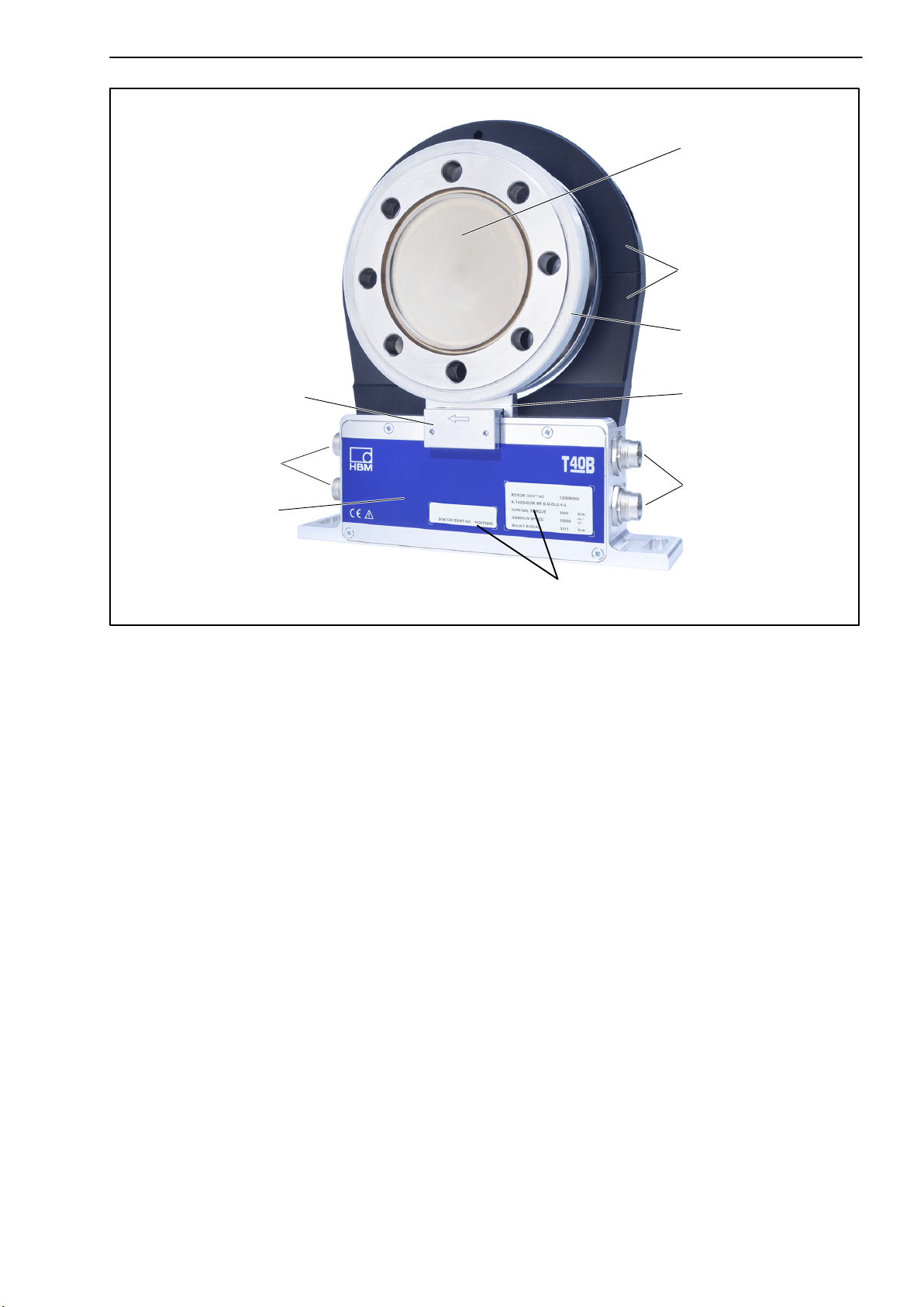
3 Structure and mode of operation
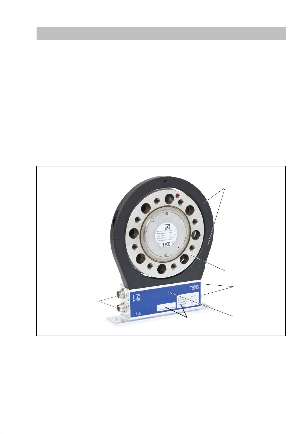
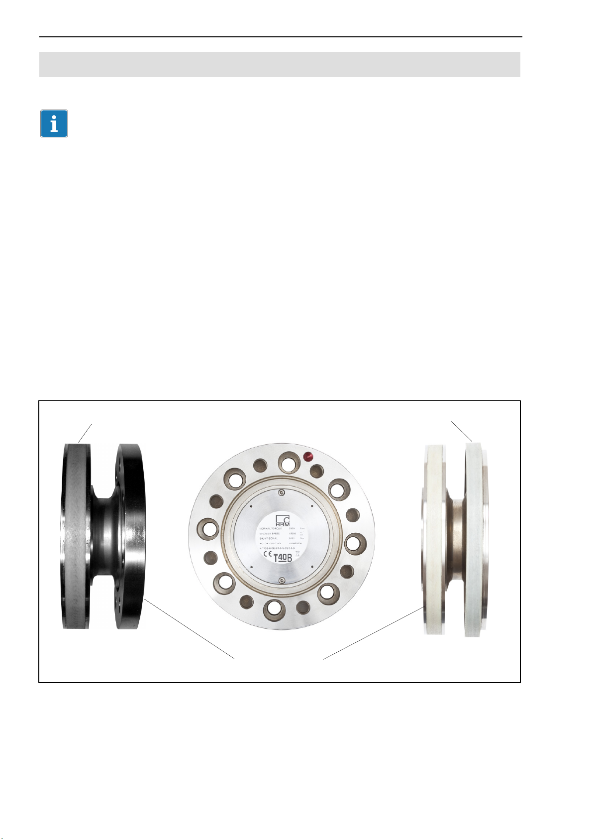
The torque flange consists of two separate parts: the rotor and the stator. The
rotor comprises the measuring body and the signal transmission elements.
Strain gauges (SGs) are installed on the measuring body. The rotor electronics for transmitting the bridge excitation voltage and the measurement signal
are located centrally in the flange. The transmitter coils for contactless transmission of excitation voltage and measurement signal are located on the
measuring body's outer circumference. The signals are sent and received by
a separable antenna ring. The antenna ring is mounted on a housing that contains the electronics for voltage adaptation and the signal conditioning.
Connector plugs for the torque and speed signals, the voltage supply and
digital output, are located on the stator. The antenna segments (ring) should
be mounted more or less concentrically around the rotor (see chapter 4).
Connector plugs
Antenna segments
Rotor
Connector plugs
Stator housing
Type plate
Fig. 3.1: Mechanical construction without a rotational speed measuring system
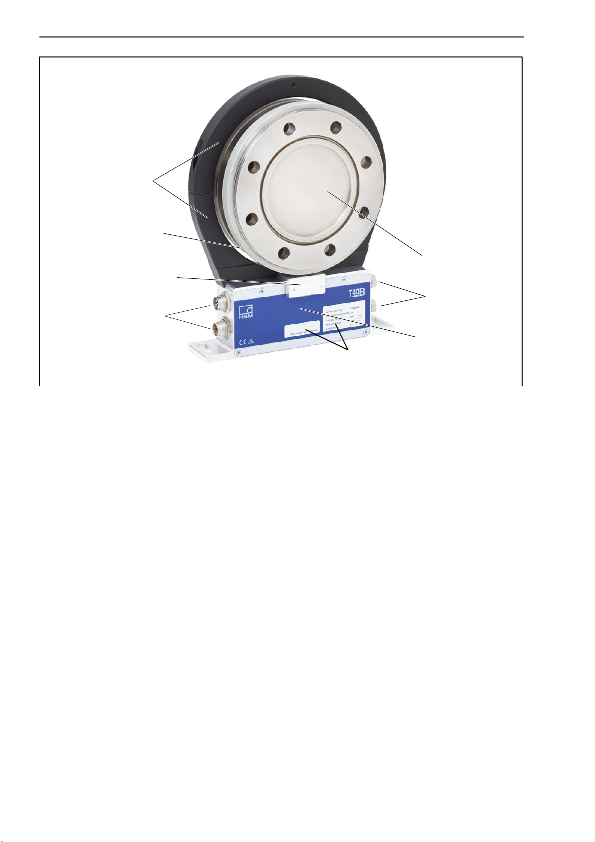
The speed sensor is mounted on the stator in Option 6 with a rotational speed
measuring system. The rotational speed is measured magnetically via an
AMR sensor and a magnetic ring. The magnetic ring for measurement of rotational speed is welded to the flange.
A3452-5.0 en/de HBM
Page 10
10
Antenna segments
Magnetic ring for measuring
rotational speed
Sensor head for measuring
rotational speed
Connector plugs
T40B
Rotor
Connector plugs
Stator housing
Type plate
Fig. 3.2: Mechanical construction with a rotational speed measuring system
In the version with a rotational speed measuring system, the transducer can
also be fitted with a sensor head for a reference signal (zero index) for measuring the angle of rotation. The magnet to be used for this is located on the
inner surface of the flange. The sensor head for sampling the reference signal
is located in the bracket above the speed sensor.
A3452-5.0 en/deHBM
Page 11
T40B
Sensor head for measuring
rotational speed
Connector plugs
Stator housing
11
Rotor
Antenna segments
Magnetic ring for
measuring rotational
speed
Sensor head for
the reference
signal
Connector plugs
Type plate
Fig. 3.3: Mechanical construction with rotational speed measuring system and
sensor for the reference signal (zero index)
A3452-5.0 en/de HBM
Page 12
12
T40B
4 Mechanical installation
4.1 Important precautions during installation
NOTE
A torque flange is a precision measuring element and therefore needs careful
handling. Dropping or knocking the transducer may cause permanent damage. Make sure that the transducer cannot be overloaded, even while it is
being mounted.
Handle the transducer with care.
Check the effect of bending moments, critical rotational speeds and natural
torsional vibrations, to prevent the transducer being overloaded by
resonance sharpness.
Make sure that the transducer cannot be overloaded.
WARNING
There is a danger of the transducer breaking if it is overloaded. This can
cause danger for the operating personnel of the system in which the
transducer is installed.
Implement appropriate safety measures to avoid overloads and to protect
against resulting dangers.
If alternating loads are expected, use threadlocker (medium strength, e.g.
LOCTITE No. 242) to glue the screws into the counter thread to exclude
prestressing loss due to screw slackening.
Comply with the mounting dimensions to enable correct operation.
An appropriate shaft flange enables the T40B torque flange to be mounted dir-
ectly. It is also possible to mount a joint shaft or relevant compensating element directly on the rotor (using an intermediate flange when required). Under
no circumstances should the permissible limits specified for bending
moments, lateral and longitudinal forces be exceeded. Due to the T40B
torque flange's high torsional stiffness, dynamic shaft train changes are kept
to a minimum.
A3452-5.0 en/deHBM
Page 13

T40B
13
Important
Even if the unit is installed correctly, the zero point adjustment made at the
factory can shift by up to approx. 2% of the sensitivity. If this value is
exceeded, we advise you to check the mounting conditions. If the residual
zero offset when the unit is removed is greater than 1% of the sensitivity,
please send the transducer back to the Darmstadt factory for testing.
4.2 Conditions on site
The T40B torque flange must be protected against coarse dirt particles, dust,
oil, solvents and humidity.
There is wide ranging compensation for the effects of temperature on the output and zero signals of the transducer (see “Specifications" section). If there
are no static temperature ratios, for example, because of the temperature differences between the measuring body and the flange, the values given in the
specifications can be exceeded. In this case, ensure static temperature ratios
by cooling or heating, depending on the application. As an alternative, check if
thermal decoupling is possible, e.g. by means of heat radiating elements such
as multiple disc couplings.
4.3 Installation orientation
The torque flange can be installed with any orientation.
With clockwise torque, the output frequency is 60 90 kHz for Option 5,
Code DU2 (Option 5, Code SU2: 10 15 kHz; Option HU2: 240 360kHz).
In conjunction with HBM amplifiers or when using the voltage output, a positive output signal (0 V +10 V) is present. In the case of the rotational speed
measuring system, an arrow is attached to the stator housing to clearly define
the direction of rotation. If the measurement flange turns in the direction of the
arrow, connected HBM measuring amplifiers deliver a positive output signal.
4.4 Installation options
There are basically two options for mounting the torque flange: with or without
dismantling the antenna ring. We recommend mounting as described in
Chapter 4.4.1. If mounting in accordance with Chapter 4.4.1 is not possible,
(e.g. in the case of subsequent stator replacement), you will have to dismantle
the antenna ring. It is essential in this case to comply with the notes on
assembling the antenna segments (see Chapter 4.4.2).
A3452-5.0 en/de HBM
Page 14
14
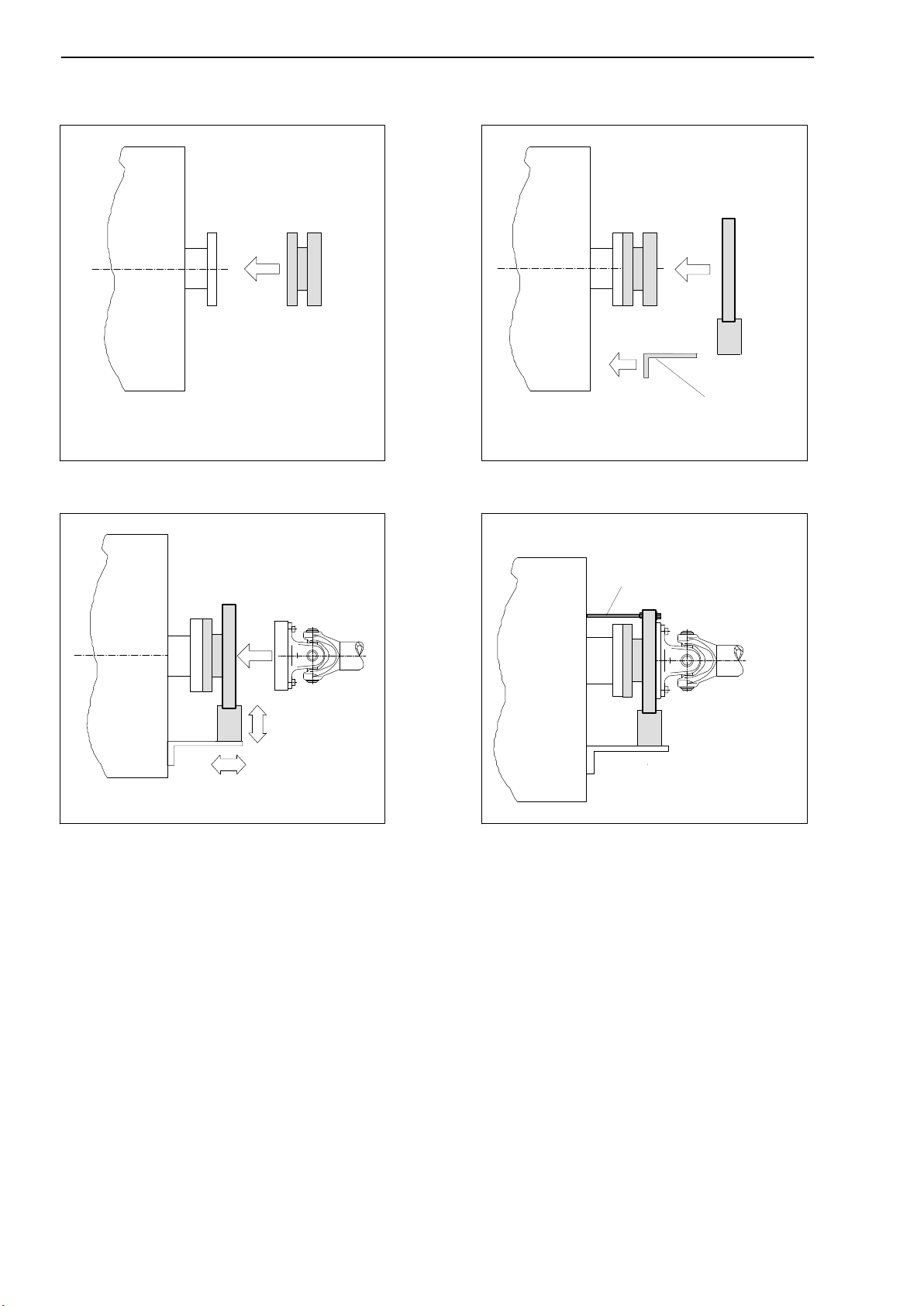
4.4.1 Installation without dismantling the antenna ring
T40B
1. Install rotor
3. Finish installation of shaft run
2. Install stator
4. Mount support
Customer
Support supplied by customer
mounting
A3452-5.0 en/deHBM
Page 15
T40B
4.4.2 Installation with subsequent stator mounting
15
1. Install rotor
Washers
Fan‐type lock
washers
3. Dismantle antenna segment
Support supplied by customer
2. Install shaft train
4. Install antenna segment
4. Mount support
A3452-5.0 en/de HBM
Page 16
16
T40B
4.5 Mounting the rotor
Tip
Usually the rotor type plate is no longer visible after installation. This is why
we include with the rotor additional stickers with the important characteristics,
which you can attach to the stator or any other relevant test‐bench components. You can then refer to them whenever there is anything you wish to know,
such as the shunt signal. To explicitly assign the data, the identification number and the size are engraved on the rotor flange, where they can be seen
from outside.
1. Prior to installation, clean the plane faces of the transducer flange and the
counter flange.
For safe torque transfer, the faces must be clean and free from grease.
Use a piece of cloth or paper soaked in solvent. When cleaning, make sure
that you do not damage the transmitter winding or the rotational speed
measuring system.
Transmitter winding
Rotational speed measuring system
Without rotational speed
measuring system
Fig. 4.1: Bolted rotor connection
Flange plane faces
With rotational speed
measuring system
A3452-5.0 en/deHBM
Page 17

T40B
17
2. For the bolted rotor connection (see Fig. 4.1), use six or eight DIN EN ISO
4762 hexagon socket screws of the property class stated in Table 4.1, in a
suitable length (dependent on the connection geometry, see Table 4.1 on
page 18).
We recommend DIN EN ISO 4762 socket head cap screws, blackened,
smooth‐headed, permitted size and shape variance in accordance with DIN
ISO 4759, Part 1, product class A.
Important
If alternating loads are expected, use threadlocker (medium strength, e.g.
LOCTITE No. 242) to glue the screws into the counter thread to exclude
prestressing loss due to screw slackening.
3. Fasten all screws with the specified torque (Table 4.1 on page 18).
4. There are eight tapped holes on the rotor for the further mounting of the
shaft run. Also use screws of property class 10.9 or 12.9 and fasten them
with the torque specified in Table 4.1.
Important
If alternating loads are expected, use threadlocker (medium strength, e.g.
LOCTITE No. 242) to glue the screws into the counter thread to exclude
prestressing loss due to screw slackening.
NOTE
Comply with the maximum thread reach as per Table 4.1. Otherwise significant measurement errors may result from torque shunt, or the transducer may
be damaged.
Measuring range Fastening bolts Prescribed tightening
moment
NVm Z
200 M8
500 M10 67
1 k M10 67
2 k M12 115
A3452-5.0 en/de HBM
1)
Property class NVm
34
10.9
Page 18
18
T40B
Measuring range Prescribed tightening
NVmNVmProperty classZ
3 k M12
5 k M14 220
10 k M16 340
Fastening bolts
moment
1)
135
12.9
Table 4.1: Fastening bolts
1)
DIN EN ISO 4762; black/oiled/m
= 0.125
tot
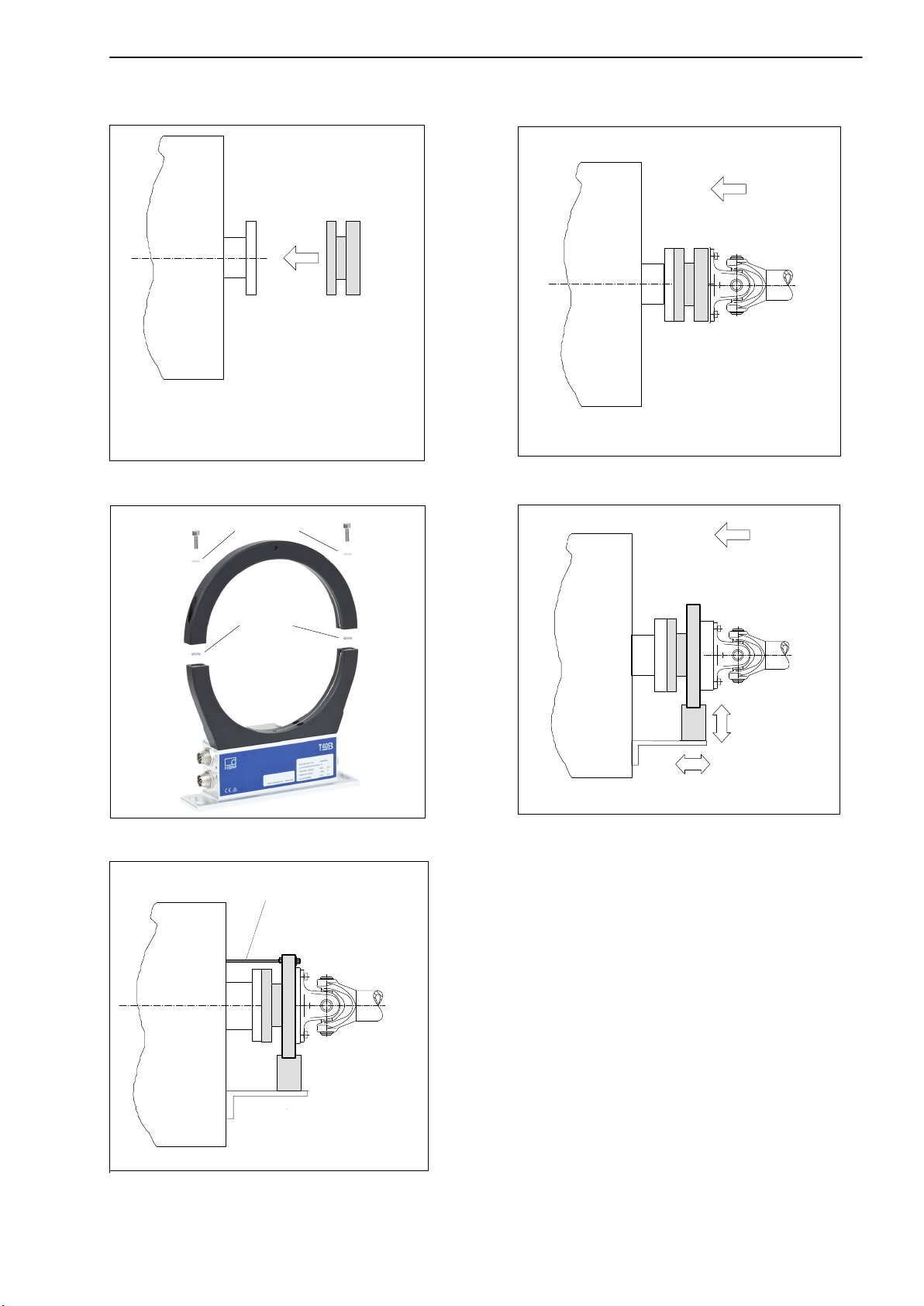
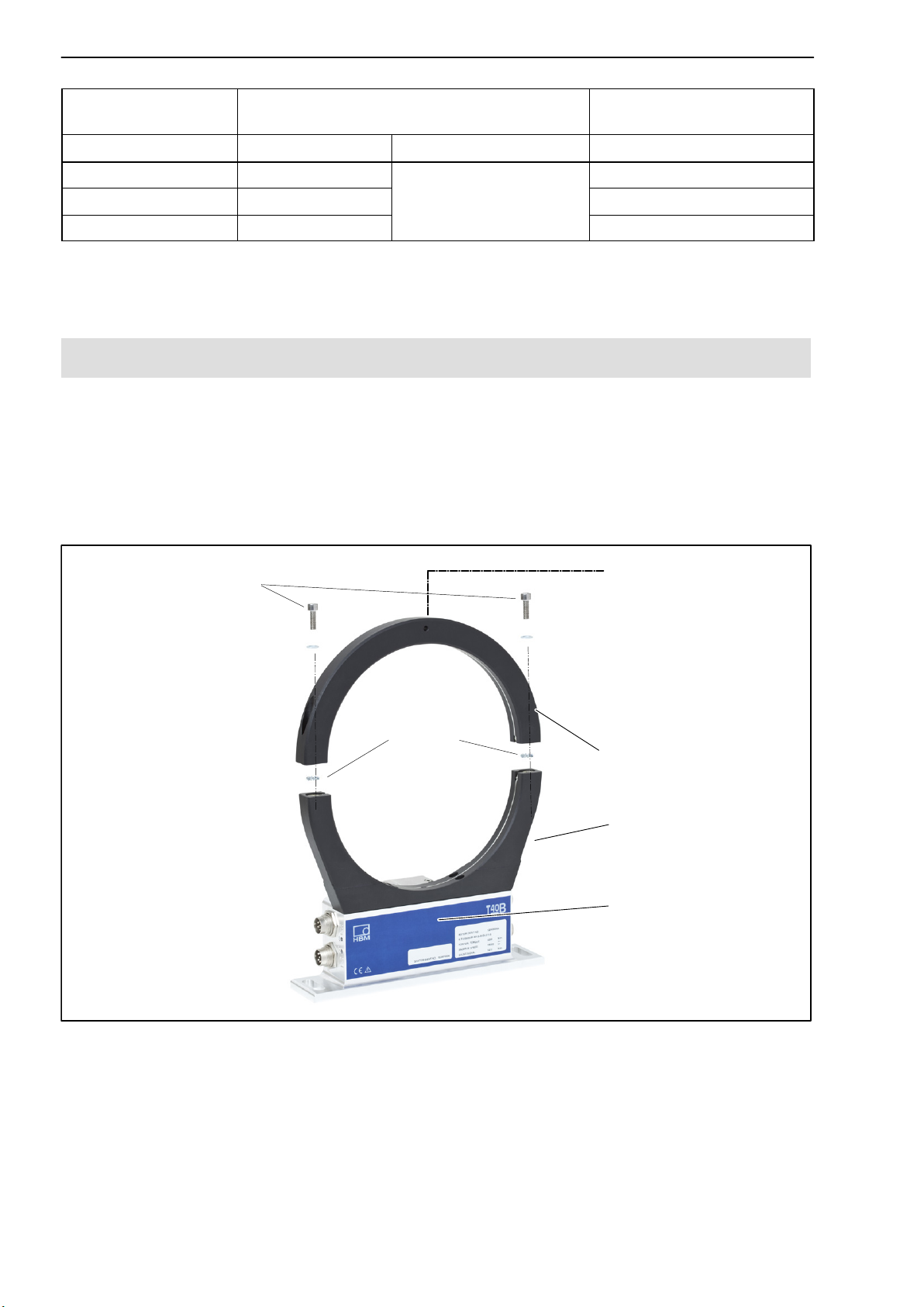
4.6 Installing the stator
On delivery, the stator has already been installed and is ready for operation.
The upper antenna segment can be separated from the stator, for example,
for maintenance or to facilitate stator mounting.
If your application does not require the stator to be dismantled, proceed as
described in points 2, 5, and 6.
Antenna segment bolts
with washers (M5)
Fan‐type lock washers
Hole for fixing the
antenna segment,
diameter 4.2 or
5.2mm, depending
on maximum
capacity
upper
antenna segments
lower
Stator housing
Fig. 4.2: Bolted connection of the antenna segments on the stator
A3452-5.0 en/deHBM
Page 19
T40B
19
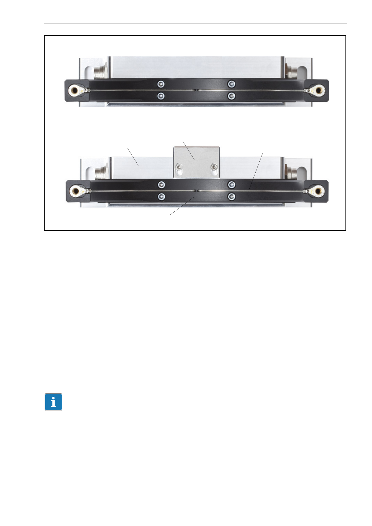
T40B without a rotational speed measuring system
T40B with a rotational speed measuring system
Sensor head for measuring rotational speed
Stator housing
Antenna wire
Lower antenna segment
Fig. 4.3: Stator housing and lower antenna segment with antenna wire
1. Undo and remove the bolted connections (M5) on the upper antenna segment.
There are fan‐type lock washers between the antenna segments: make
sure that they do not get lost.
2. Use an appropriate mounting base to install the stator housing in the shaft
train so that there is sufficient opportunity for horizontal and vertical adjustments. Do not fully tighten the bolts yet.
3. Now use two hexagon socket screws to mount the upper antenna segment
removed in Point 1 on the lower antenna segment.
Make sure that the two fan‐type lock washers are inserted between the antenna
segments (these ensure that there is a defined contact resistance)!
Important
To make sure that they function perfectly, the fan‐type lock washers (A5,
3-FST DIN 6798 ZN/galvanized) must be replaced after the bolted antenna
connection has been loosened three times.
4. Now tighten all antenna‐segment bolted connections with a tightening
torque of 5 Nm.
A3452-5.0 en/de HBM
Page 20
20
T40B
5. Rotational speed measurement without a sensor for the reference signal
(zero index):
Then align the antenna to the rotor in such a way that the antenna
encloses the rotor more or less coaxially and the antenna wire in the
axial direction has the same position as the center of the transmitter
winding on the rotor.
To make this alignment easier, the antenna segment and the transmitter
winding on flange B have the same width. Please comply with the permissible alignment tolerances stated in the specifications.
Fig. 4.4: Alignment of the rotor with the stator (without a reference signal
sensor)
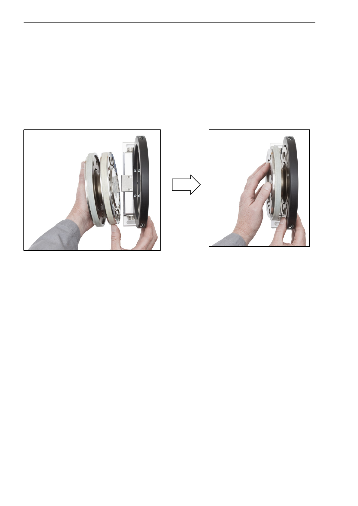
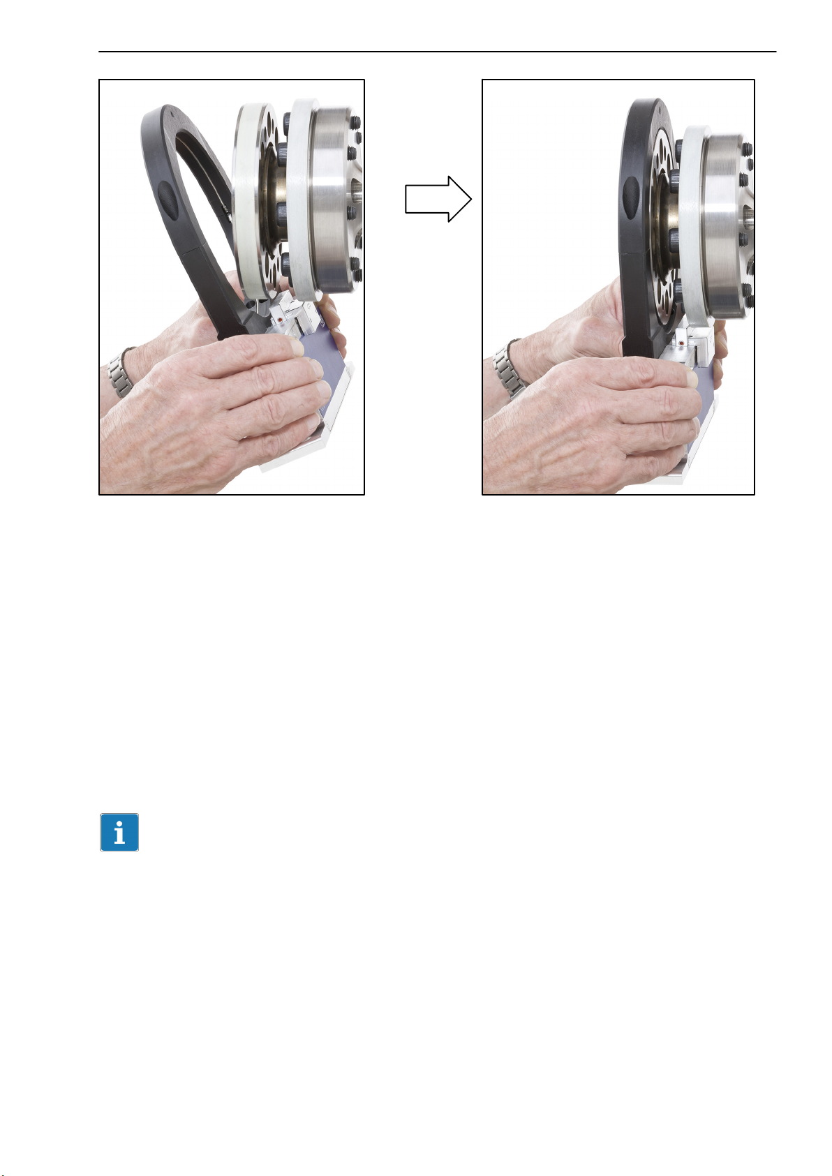
Rotational speed measurement with a sensor for the reference signal (zero
index):
Tilt the stator slightly (see Fig. 4.5, left), so that the bracket with the
sensor head for the reference signal (zero index) is between the two
flanges. Now tip the stator over the rotor until the antenna ring completely covers the flange with the transmitter winding (see Fig. 4.5, right).
A3452-5.0 en/deHBM
Page 21
T40B
21
Fig. 4.5: Alignment of the rotor with the stator (with a reference signal sensor)
6. Now fully tighten the bolted stator housing connection.
Prevention of stator axial oscillation
Depending on the operating conditions, the stator may be induced to oscillate.
This effect is dependent on:
the rotational speed,
the antenna diameter (depends in turn on the measuring range),
the design of the machine base.
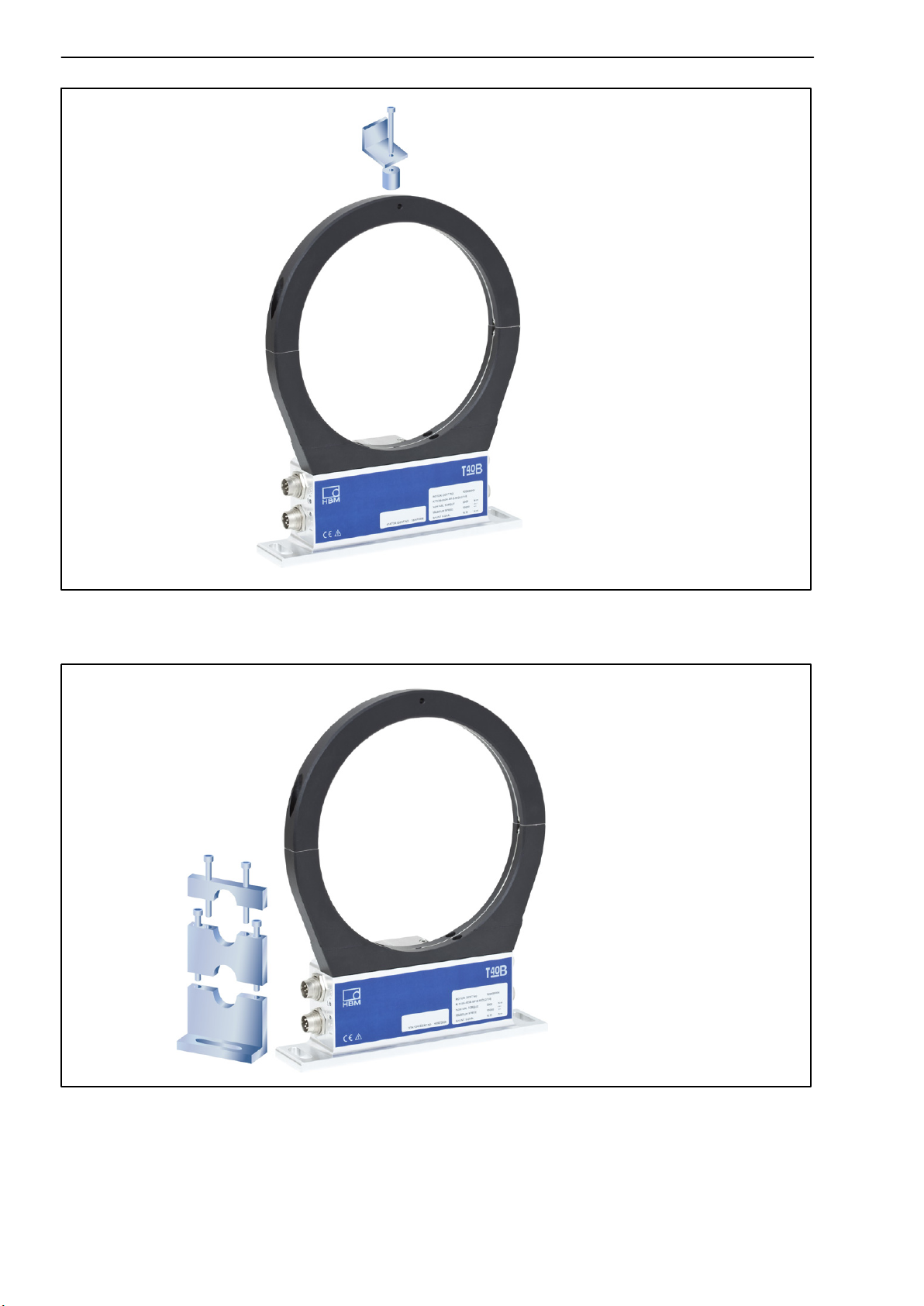
Important
To prevent this axial oscillation, the antenna ring requires additional support
by the customer. There is a socket (with an M5 internal thread) on the upper
antenna segment, which can be used for a suitable clamping device (see
Fig. 4.6).
If this is the case, the cable plug also needs some support, as shown in the
construction example in Fig. 4.7.
A3452-5.0 en/de HBM
Page 22
22
T40B
Fig. 4.6: Construction example for supporting the antenna ring
Fig. 4.7: Construction example for plug clamps (for two plugs)
A3452-5.0 en/deHBM
Page 23
T40B
23
4.7 Rotational speed measuring system, reference signal (optional)
The optional rotational speed measuring system (also with the additional reference signal and zero index option) is integrated into the transducer at the
factory, so no installation is required.
Magnetic ring for rotational
speed measurement
Sensor head for the
reference signal
Sensor head for rotational
speed measurement
Fig. 4.8: Torque transducer with rotational speed measurement and reference sig-
nal
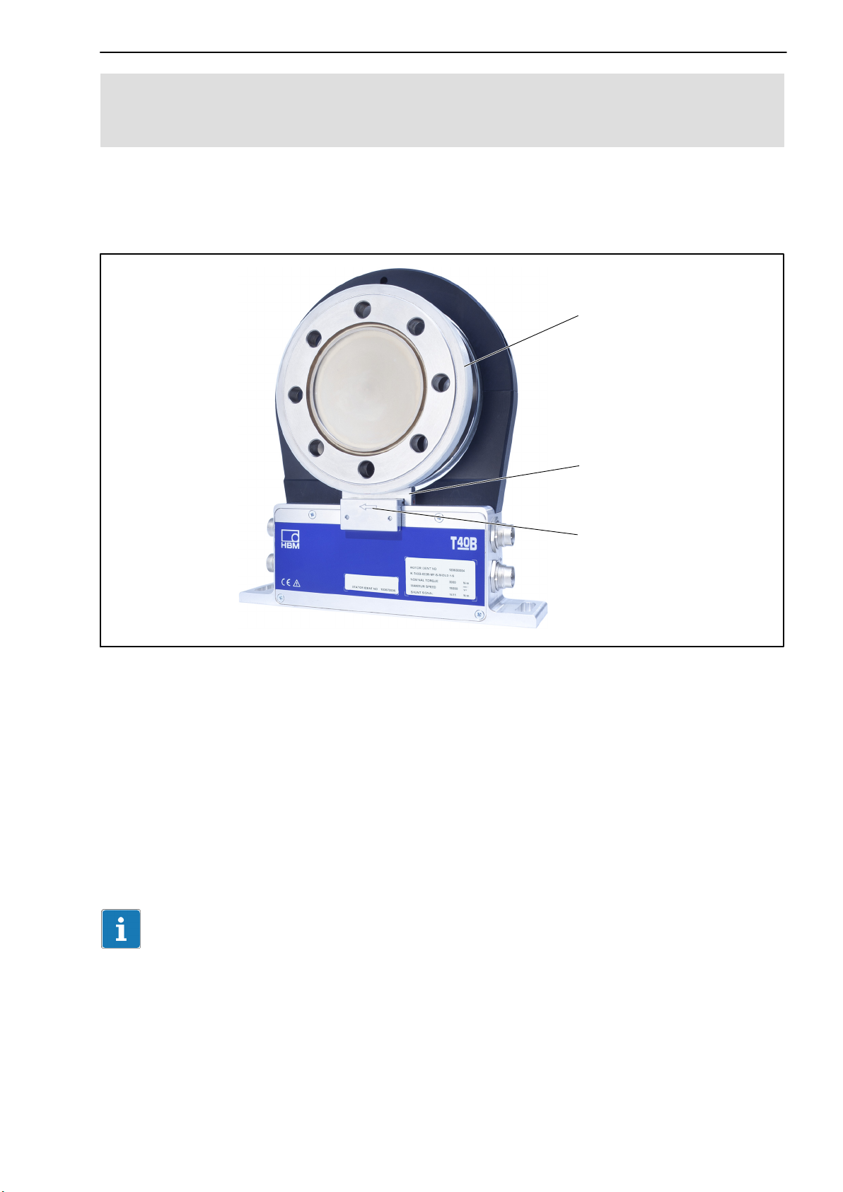
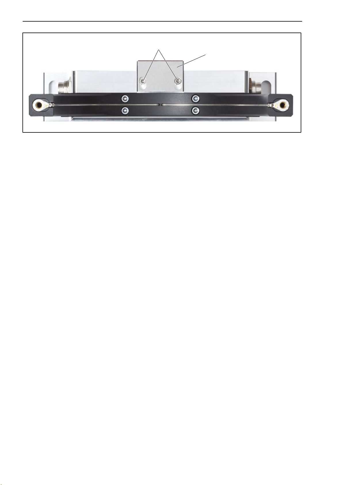
Rotational speed measuring system sensor head alignment
If the stator is accurately aligned for torque measurement, the rotational
speed measuring system and the sensor for the reference signal (zero index)
are also correctly aligned. So the two Allen screws on the sensor head
(Fig. 4.9) must not be loosened.
Important
You must not change the position of the sensor head.
A3452-5.0 en/de HBM
Page 24
24
Never loosen the screws!
Sensor head for rotational
speed measurement
T40B
Fig. 4.9: Torque transducer with sensor head for rotational speed measurement
A3452-5.0 en/deHBM
Page 25

T40B
25
5 Electrical connection
5.1 General information
With cable extensions, make sure that there is a proper connection with
minimum contact resistance and good insulation.
All cable connectors or swivel nuts must be fully tightened.
Important
Transducer connection cables from HBM with plugs attached are identified in
accordance with their intended purpose (Md or n). When cables are
shortened, inserted into cable ducts or installed in control cabinets, this identification can get lost or become concealed. So the cables must be marked
beforehand, just in case.
5.2 EMC protection
Important
The transducers are EMC‐tested in accordance with EC directives and identified by CE certification. However, you must connect the shield of the connection cable on the shielding electronics enclosure in order to achieve EMC protection for the measuring chain.
Special electronic coding methods are used to protect the purely digital signal
transmission between the transmitter head and the rotor from electromagnetic
interference.
The cable shield is connected with the transducer housing. This encloses the
measurement system (without the rotor) in a Faraday cage when the shield is
laid flat at both ends of the cable. With other connection techniques, an
EMC-proof shield should be applied in the wire area and this shielding should
also be connected extensively (also see HBM Greenline Information, brochure
i1577).
Electrical and magnetic fields often induce interference voltages in the measuring circuit. Therefore:
Use shielded, low‐capacitance measurement cables only (HBM cables ful-
fill both conditions).
Only use plugs that meet EMC guidelines.
A3452-5.0 en/de HBM
Page 26

26
T40B
Do not route the measurement cables parallel to power lines and control cir-
cuits. If this is not possible, protect the measurement cable withsteel conduits,
for example.
Avoid stray fields from transformers, motors and contact switches.
Do not ground the transducer, amplifier and indicator more than once.
Connect all devices in the measuring chain to the same protective earth
conductor.
In the case of interference due to potential differences (compensating cur-
rents), the connection between supply voltage zero and housing ground
must be broken at the amplifier and a potential equalization line established
between the stator housing and the amplifier housing (copper conductor, at
2
least 10 mm
wire cross-section).
Should differences in potential occur between the machine rotor and stator
because of unchecked leakage, for example, this can usually be overcome
by connecting the rotor definitively to ground, e.g. with a wire loop. The
stator must be connected to the same (ground) potential.
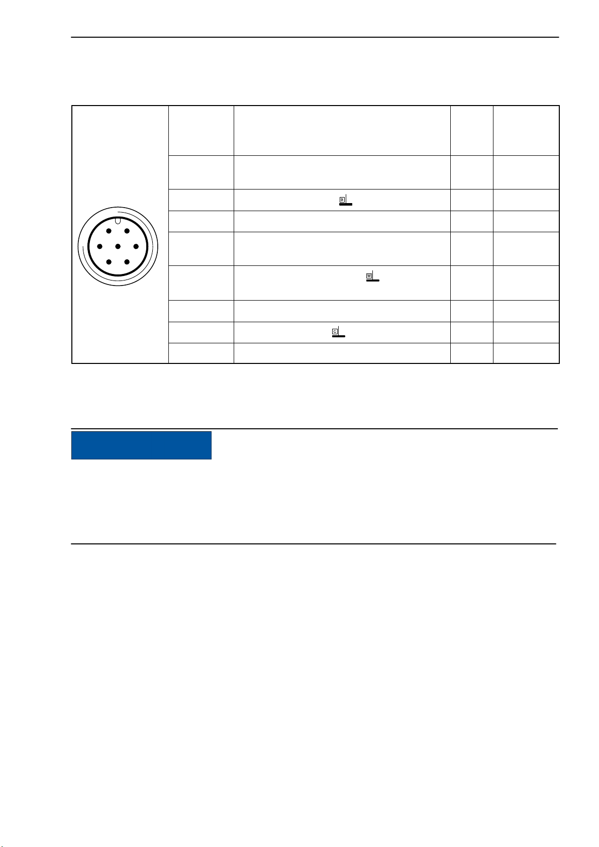
5.3 Connector pin assignment
The stator housing has two 7‐pin connectors, an 8‐pin connector and a 1‐pin
connector.
The supply voltage connections and shunt signal connections of connectors 1
and 3 are each electrically interconnected, but are protected against compensating currents by diodes. There is also an automatically resetting fuse
(multifuse) to protect the supply connections against overload by the stator.
A3452-5.0 en/deHBM
Page 27
T40B
Assignment for connector 1:
Supply voltage and frequency output signal.
27
Connector
pin
Device plug
61
5
72
3
4
Top view
1)
RS-422 complementary signals; with cable lengths exceeding 10 m, we recommend
1
2 Supply voltage 0 V; bk 5
3 Supply voltage 18 V 30 V bu 6
4
5
6 Shunt signal trigger 5 V 30 V gn 14
7 Shunt signal 0 V; gy 8
Assignment Color
code
Torque measurement signal
(frequency output; 5 V
Torque measurement signal
(frequency output; 5 V
Measurement signal 0 V;
symmetrical
Shielding connected to housing ground
1),2)
) wh 13
1),2)
) rd 12
gy 8
using a termination resistor R = 120 ohms between the (wh) and (rd) wires.
2)
RS-422: Pin 1 corresponds to A, Pin 4 corresponds to B.
Sub‐D
connector
pin
NOTE
Torque flanges are only intended for operation with a DC supply voltage. They
must not be connected to older HBM amplifiers with square‐wave excitation.
This could destroy the connection board resistors or cause other faults in the
amplifiers.
A3452-5.0 en/de HBM
Page 28
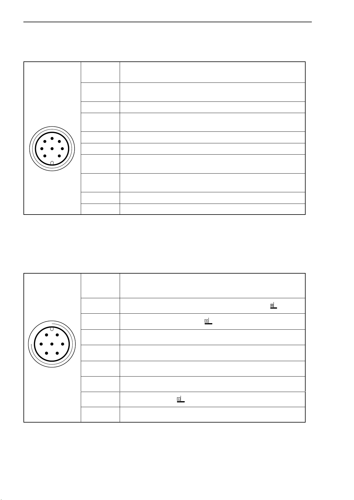
28
Assignment for connector 2:
Rotational speed output signal, reference signal (optional).
T40B
Connector
Assignment
pin
1)
1)
1)
1)
1)
1)
Device plug
2
5
3
4
8
1
6
7
Top view
1
Rotational speed measurement signal
(pulse string, 5 V; 0)
2 Reference signal (1 pulse/revolution, 5V)
3
Rotational speed measurement signal
(pulse string, 5 V; 90phase shifted)
4 Reference signal (1 pulse/revolution, 5V)
5 Not in use
6
7
Rotational speed measurement signal
(pulse string, 5 V; 0)
Rotational speed measurement signal
(pulse string, 5 V; 90phase shifted)
8 Operating voltage zero
Shielding connected to housing ground
1)
RS-422 complementary signals; with cable lengths exceeding 10 m, we recommend
using a termination resistor of R = 120 ohms.
Assignment for connector 3:
Supply voltage and voltage output signal.
Device plug
61
72
5
3
4
Top view
Connector
pin
1 Torque measurement signal (voltage output; 0 V )
2
3 Supply voltage 18 V 30 V DC
4
5 Not in use
6 Shunt signal trigger 5 V 30 V
7 Shunt signal 0 V;
Assignment
Supply voltage 0 V;
Torque measurement signal (voltage output; "10 V)
Shielding connected to housing ground
Assignment for connector 4:
TMC - only for connection to the TIM 40 Torque Interface Module within HBM.
A3452-5.0 en/deHBM
Page 29

T40B
29
5.4 Supply voltage
The transducer must be operated with a separated extra‐low voltage (nominal
(rated) supply voltage 18 30 V
flanges within a test bench at the same time. Should the device be operated
1)
on a DC voltage network
, additional precautions must be taken to discharge
excess voltages.
The information in this section relates to the self‐contained operation of the
T40B, without HBM system solutions.
The supply voltage is electrically isolated from signal outputs and shunt signal
inputs. Connect a separated extra‐low voltage of 18 V 30 V to pin 3 (+) and
). You can supply one or more torque
DC
pin 2 (
) of connectors 1 or 3. We recommend that you use HBM cable KAB
8/00-2/2/2 and the appropriate sockets (see Accessories). The cable can be
up to 50 m long for voltages 24 V, otherwise it can be up to 20 m long.
If the permissible cable length is exceeded, you can supply the voltage in parallel over two connection cables (connectors 1 and 3). This enables you to
double the permissible length. Alternatively, install a power supply on site.
Important
The instant you switch on, a current of up to 4 A may flow and this may switch
off power supplies with electronic current limiters.
1)
Distribution system for electrical energy with greater physical expansion (over several test benches, for
example) that may possibly also supply consumers with high nominal (rated) currents.
A3452-5.0 en/de HBM
Page 30

30
T40B
6 Shunt signal
The T40B torque flange delivers an electrical shunt signal that can be activated from the amplifier in measuring chains with HBM components. The transducer generates a shunt signal of about 50% of the nominal (rated) torque;
the precise value is specified on the type plate. After activation, adjust the
amplifier output signal to the shunt signal supplied by the connected transducer to adapt the amplifier to the transducer.
The transducer should not be under load when the shunt signal is being
measured, as the shunt signal is mixed additively.
Triggering the shunt signal
Applying a separated extra‐low voltage of 5 30 V to pins 6 (+) and 7 (
connector 1 or 3 triggers the shunt signal.
The nominal (rated) voltage for triggering the shunt signal is 5 V (triggering at
U > 2.5 V), but when voltages are less than 0.7 V, the transducer is in measuring mode. The maximum permissible voltage is 30 V, current consumption
at nominal (rated) voltage is approx. 2 mA and at maximum voltage, approx.
18 mA. The voltage for triggering the shunt signal is electrically isolated from
the supply and measuring voltage.
) at
Tip
The shunt signal can be triggered by the amplifier or via the operating software in HBM system solutions.
A3452-5.0 en/deHBM
Page 31

T40B
7 Functional testing
You can check the functionality of the rotor and the stator from the LEDs on
the stator.
LED A, rotor status
LED B, stator status
31
Fig. 7.1: LEDs on the stator housing
7.1 Rotor status, LED A (upper LED)
Color Significance
Green (pulsating) Internal rotor voltage values ok
Rotor and stator mismatched (an increasing flashing
Flashing orange
Pulsating orange
Red (pulsating)
frequency indicates the degree of misalignment)
=> Correct the rotor/stator alignment
Rotor status cannot be defined
=> Correct the rotor/stator alignment
If the LED still pulsates orange, it is possible that there is a
hardware defect. The measurement signals reflect the level of
the defect status.
Rotor voltage values not ok.
=> Correct the rotor/stator alignment
If the LED still pulsates red, it is possible that there is a
hardware defect. The measurement signals reflect the level of
the defect status.
Pulsating means that the LED goes dark for about 20 ms every second (sign
of life), making it possible to detect that the transducer is functioning.
A3452-5.0 en/de HBM
Page 32

32
7.2 Stator status, LED B (lower LED)
Color Significance
T40B
Green
(permanently lit)
Green, intermittently
orange.
Numerous
synchronization defects:
permanently orange
Orange
(permanently lit)
Red
(permanently lit)
Measurement signal transmission and internal stator voltages ok
Orange until end of defective transmission if y5 incorrect
measured values in sequence are transmitted. The
measurement signals reflect the level of the defect status for the
duration of the transmission defect + for approx. another 3.3 ms.
Permanently disrupted transmission, the measurement signals
reflect the level of the defect status. (f
= 0 Hz, U
out
= defect
out
level).
=> Correct the rotor/stator alignment.
Internal stator defect, the measurement signals reflect the
level of the defect status (f
= 0 Hz, U
out
= defect level).
out
A3452-5.0 en/deHBM
Page 33

T40B
33
8 Load‐carrying capacity
Nominal (rated) torque can be exceeded statically up to the limit torque. If the
nominal (rated) torque is exceeded, additional irregular loading is not permissible. This includes longitudinal forces, lateral forces and bending moments.
Limit values can be found in the “Specifications" chapter (Chapter 12,
page
Measuring dynamic torque
The torque flange can be used to measure static and dynamic torque. The following rule applies to the measurement of dynamic torque:
The T40B calibration performed for static measurements is also valid for
36).
dynamic torque measurements.
The natural frequency f
depends on the moments of inertia J
of the mechanical measuring arrangement
0
and J2 of the connected rotating
1
masses and the torsional stiffness of the T40B.
Use the equation below to approximately determine the natural frequency f
the mechanical measuring arrangement:
f0+
1
· cT·
Ǹ
2p
ǒ
f
)
1
Ǔ
J
2
1
J
1
0
J
c
= natural frequency in Hz
J2= mass moment of inertia in kgm
1,
= torsional stiffness in Nm/rad
T
2
The permissible mechanical oscillation width (peak‐to‐peak) can also be
found in the specifications.
Nominal (rated) torque M
+ M
nom
nom
as a %
of
0
Oscillation width
- M
nom
Oscillation width
0
Time t
Oscillation width
200% oscillation width
Fig. 8.1: Permissible dynamic loading
A3452-5.0 en/de HBM
Page 34

34
T40B
9 Maintenance
T40B torque flanges are maintenance‐free.
10 Waste disposal and environmental protection
All electrical and electronic products must be disposed of as hazardous
waste. The correct disposal of old equipment prevents ecological damage and
health hazards.
Symbol:
Meaning: Statutory waste disposal mark
The electrical and electronic devices that bear this symbol are subject to the
European waste electrical and electronic equipment directive 2002/96/EC.
The symbol indicates that, in accordance with national and local environmental protection and material recovery and recycling regulations, old devices
that can no longer be used must be disposed of separately and not with normal household garbage.
As waste disposal regulations may differ from country to country, we ask that
you contact your supplier to determine what type of disposal or recycling is
legally applicable in your country.
Packaging
The original packaging of HBM devices is made from recyclable material and
can be sent for recycling. Store the packaging for at least the duration of the
warranty. In the case of complaints, the torque flange must be returned in the
original packaging.
For ecological reasons, empty packaging should not be returned to us.
A3452-5.0 en/deHBM
Page 35

T40B
11 Ordering numbers, accessories
35
Accessories, to be ordered separately
Article Order no.
Connection cable, set
Torque connection cable, Binder 423 - 15‐pin D-Sub, 6 m 1-KAB149-6
Torque connection cable, Binder 423 - 7‐pin, free ends, 6 m 1-KAB153-6
Rotational speed connection cable, Binder 423 - 15‐pin D-Sub, 6 m 1-KAB150-6
Rotational speed connection cable, Binder 423 - 8‐pin, free ends, 6 m 1-KAB154-6
Rotational speed connection cable, reference signal, Binder 423 - 15‐pin D-Sub, 6 m 1-KAB163-6
Rotational speed connection cable, reference signal, Binder 423 - 8‐pin, free ends, 6 m 1-KAB164-6
TMC connection cable, Binder 423 - 16‐pin, free ends, 6 m 1-KAB174-6
Cable sockets
423G-7S, 7 pin (straight) 3-3101.0247
423W-7S, 7 pin (angle) 3-3312.0281
423G-8S, 8‐pin (straight) 3-3312.0120
423W-8S, 8‐pin (angle) 3-3312.0282
Connection cable, by the meter (min. order quantity: 10 m, price per meter)
Kab8/00-2/2/2 4-3301.0071
A3452-5.0 en/de HBM
Page 36

36
T40B
12 Specifications
Type T40B
Accuracy class 0.05
Torque measuring system
Nominal (rated) torque M
nom
Nominal (rated) rotational speed rpm 20000 15000 12000 10000
Non‐linearity including hysteresis, relative to
the nominal (rated) sensitivity
Frequency output %
Voltage output %
Relative standard deviation of repeatability
per DIN 1319, relative to the variation of the
output signal
Frequency output %
Voltage output %
Temperature effect per 10 K in nominal
(rated) temperature range
on the output signal, relative to the actual
value of the signal spread
Frequency output
Voltage output %
on the zero signal, relative to the nominal
(rated) sensitivity
Frequency output
Voltage output %
Nominal (rated) sensitivity (spread between
torque = zero and nominal (rated) torque)
Freq. output 10kHz / 60kHz / 240kHz
Voltage output
Sensitivity tolerance (deviation of the actual
output quantity at M
from the nominal (rated)
nom
sensitivity)
Output signal at torque = zero
Frequency output kHz 10/60/240
Voltage output V 0
Nominal (rated) output signal
Frequency output
with positive nominal (rated) torque kHz
with negative nominal (rated) torque kHz
Voltage output
with positive nominal (rated) torque V +10
with negative nominal (rated) torque V -10
1)
Option 5, 10"5 kHz (code SU2)
2)
Option 5, 60"30 kHz (code DU2)
3)
Option 5, 240"120 kHz (code HU2)
4)
RS-422 complementary signals, note termination resistor .
Nm 200 500
kNm 1 2 3 5 10
<"0.03
<"0.03
<"0.03
<"0.03
%
"0.05
"0.2
%
"0.05
"0.1
kHz
V
5/30/120
10
"0.1
15
1)
/ 90
2)
/ 360
3)
(5 V symmetrical 4))
1)
5
(5 V symmetrical
/ 30
2)
/ 120 3)
4)
)
A3452-5.0 en/deHBM
Page 37

T40B
37
Nominal (rated) torque M
nom
Nm 200 500
kNm 1 2 3 5 10
Load resistance
Frequency output k 2
Voltage output k 10
Longterm drift over 48 h
Frequency output
%
Voltage output %
Measurement frequency range, -3 dB kHz 11) / 32) / 6
t"0.03
t"0.03
3)
Group delay s t4001) / t2202) / t150
Residual ripple
Voltage output
Maximum modulation range
Frequency output
5)
6)
mV t40
2.5 17.5
kHz
1)
/ 15 105
60 420
3)
Voltage output V -12 +12
Energy supply
Nominal (rated) supply voltage (separated
extra‐low DC voltage)
V 18 30
Current consumption in measuring mode A < 1
Current consumption in startup mode A < 4 (typ. 2) 50 s
Nominal (rated) power consumption W < 10
Maximum cable length m 50
Shunt signal approx. 50 % of M
Tolerance of the shunt signal, relative to
M
nom
Nominal (rated) trigger voltage
Trigger voltage limit
Shunt signal ON
Shunt signal OFF
5)
Signal frequency range 0.1 to 10 kHz
6)
Output signal range in which there is a repeatable correlation between torque and output signal.
%
V
V
V
V
<"0.05
<"0.05
5
36
min. 2.5
max. 0.7
nom
3)
2)
/
A3452-5.0 en/de HBM
Page 38

38
T40B
Rotational speed measuring system
Nominal (rated) torque M
nom
Nm 200 500
kNm 1 2 3 5 10
Measurement system Magnetic, via AMR sensor
(Anisotropic Resistive Effect) and
magnetized plastic ring with
embedded steel ring
Magnetic poles 72 86 108 126 156
Maximum position deviation of the poles
"50 angular seconds
Output signal V 5 V symmetrical (RS-422);
2 square wave signals approx. 90
phase shifted
Pulses per revolution 1024
Minimum rotational speed for sufficient pulse
stability
Pulse tolerance
7)
rpm 0
degrees
<"0.05
Maximum permissible output frequency kHz 420
Group delay s <150
Radial nominal (rated) distance between
sensor head and magnetic ring (mechanical
distance)
mm 1.6
Working distance range between sensor head
and magnetic ring
mm 0.4 2.5
Max. permissible axial displacement of the
rotor to the stator
8)
mm
"1.5
Hysteresis of reversal in the case of relative
vibrations between the rotor and the stator
Torsional vibration of the rotor degrees approx. 0.2
Horizontal stator vibration displacement mm approx. 0.5
Magnetic load limit
Remanent flux density mT 100
Coercive field strength kA/m 100
Permissible magnetic field strength for signal
deviations
Load resistance
7)
At nominal (rated) conditions.
8)
The data refers only to a central axial alignment. Deviations lead to a change in pulse tolerance.
9)
Note the termination resistors required in accordance with RS-422.
9)
kA/m 0.1
k 2
A3452-5.0 en/deHBM
Page 39

T40B
Reference signal measuring system (zero index)
Measurement system Magnetic, via Hall sensor and magnet
Output signal V 5 V symmetrical (RS‐422)
Pulses per revolution 1
Minimum rotational speed for sufficient
pulse stability
Pulse width, approx. degrees 0.088
Pulse tolerance
10)
Group delay s <150
Axial nominal (rated) distance between
sensor head and magnetic ring (mechanical
distance)
Working distance range between sensor
head and magnetic ring
Max. permissible axial displacement of the
rotor to the stator
10)
At nominal (rated) conditions.
11)
The data refers only to a central axial alignment. Deviations lead to a change in pulse tolerance.
11)
rpm 2
degrees
<"0.05
mm 2.0
mm 0.4 2.5
mm
"1.5
39
A3452-5.0 en/de HBM
Page 40

40
General information
Nominal (rated) torque M
nom
EMC
Emission (per EN 61326-1, Section 7)
RFI field strength - Class B
Immunity from interference (EN
61326-1, Table 2)
Electromagnetic field (AM) V/m
Magnetic field A/m
Electrostatic discharge (ESD)
Contact discharge kV
Air discharge kV
Fast sweeps (burst) kV
Impulse voltages (surge) kV
Conducted interference (AM) V
Degree of protection per EN60529 IP 54
Reference temperature C
Nominal (rated) temperature range C
Operating temperature range C
Storage temperature range C
Mechanical shock per
EN60068-2-27
12)
Number n
Duration ms
Acceleration (half sine) m/s
Vibrational stress in 3 directions per
EN60068-2-6
12)
Frequency range Hz 10 2000
Duration h 2.5
Acceleration (amplitude) m/s
Load limits
Limit torque, relative to M
Breaking torque, relative to M
Longitudinal limit force
Lateral limit force
Limit bending moment
13)
15)
15)
15)
nom
14)
nom
14)
Oscillation width per DIN 50100
(peak‐to‐peak)
12)
The antenna ring and connection plug must be fixed in place.
13)
Each type of irregular stress (bending moment, lateral or longitudinal force, exceeding nominal (rated)
torque), can only be permitted up to its specified load limit, provided none of the others can occur at the
same time. If this condition is not met, the limit values must be reduced. If 30% of the limit bending
moment and lateral limit force occur at the same time, only 40% of the longitudinal limit force is permissible and the nominal (rated) torque must not be exceeded. The permissible bending moments, longitudinal forces and lateral forces can affect the measurement result by approx. 0.3% of the nominal (rated)
torque. The load limits only apply for the nominal (rated) temperature range. At temperatures t 10C,
load limits are expected to reduce by up to 30%, because there is an increased reduction in toughness as
temperatures fall.
14)
With static loading.
15)
Static and dynamic.
16)
The nominal (rated) torque must not be exceeded.
16)
Nm 200 500
kNm 1 2 3 5 10
10
100
4
8
1
1
10
23
+10 +70
-20 +85
-40 +85
1000
3
2
2
650
200
% 200 160
% > 400 > 320
kN 10 13 19 30 35 60 80
kN 2 4 5 9 10 12 18
Nm 100 200 220 560 600 800 1200
Nm 400 1000 2000 4000 4800 8000 16000
T40B
A3452-5.0 en/deHBM
Page 41

T40B
Mechanical values
Nominal (rated) torque
M
nom
Torsional stiffness c
Torsion angle at M
T
nom
Stiffness in the axial
direction c
a
Stiffness in the radial
direction c
r
Stiffness with bending
moment round a radial
axis c
b
Maximum deflection at
longitudinal limit force
Additional max. radial
deviation at lateral limit
force
Additional plumb/parallel
deviation at limit bending
moment
(with j d
)
B
Balance quality level per
DIN ISO 1940
Max. limits for relative
shaft vibration
(peak‐to‐peak)
17)
Undulation in the
connection flange area
following ISO 7919-3
Normal operation
(continuous operation)
Start and stop operation/
resonance ranges
(temporary)
Mass moment of inertia
of the rotor J
v
without rotational speed
measuring system
with magn. rotational
speed measuring system
Proportional mass
moment of inertia for the
transmitter side (side of
the flange with external
centering)
without rotational speed
measuring system
with magn. rotational
speed measuring system
17)
The influence of radial deviations, eccentricity, defects of form, notches, marks, local residual magnetism,
structural inhomogeneity or material anomalies needs to be taken into account and isolated from the
actual undulation.
Nm 200 500
kNm 1 2 3 5 10
kNm/rad 360 745 1165 2515 3210 5565 14335
degrees 0.032 0.038 0.049 0.046 0.054 0.051 0.040
kN/mm 540 450 580 540 570 760 960
kN/mm 315 560 860 1365 1680 2080 2940
kNm/
degrees
3.6 4.2 5.9 9 9.3 20.2 45.5
mm <0.04 <0.05 <0.06 <0.08 <0.09
mm <0.02
mm <0.06 <0.11 <0.09 <0.18
<0.19 <0.14 <0.12
G 2.5
m
m
kgm
kgm
% of J
% of J
s
(p p)
s
(p p)
2
0.0017 0.0039 0.0128 0.0292 0.0771
2
0.0022 0.0048 0.0145 0.0146 0.0333 0.0872
62 59 54 53 54
v
48 48 48 47 48
v
+
+
9000
Ǹ
n
13200
Ǹ
n
(n in rpm)
(n in rpm)
41
A3452-5.0 en/de HBM
Page 42

42
T40B
Nominal (rated) torque
M
nom
Nm 200 500
kNm 1 2 3 5 10
Max.permissible static
eccentricity
of the rotor (radially) to the
center point of the stator
without rotational speed
measuring system
mm
Permissible axial
displacement between
rotor and stator
18)
without rotational speed
measuring system
mm
Weight
Rotor without rotational
speed measuring system
Rotor with magn.
kg
1.1
rotational speed
measuring system
Stator
18)
Above the nominal (rated) temperature range: 1.5mm.
kg
kg
1.3
1.1
1.9
2.1
1.1
"2
"2
3.8
4.1
1.1
3.9
4.1
1.1
6.5
6.9
1.2
10.9
11.7
1.3
A3452-5.0 en/deHBM
Page 43

T40B
13 Supplementary technical information
Axial and radial run‐out tolerances
B
Axial run‐out AB
Radial run‐out AB
Internal centering
Hardness 46 to 54 HRC
Surface quality of the axial and radial
0.8
run‐out surfaces (A, B and AB)
Measuring range (NVm) Axial run‐out tolerance (mm) Radial run‐out tolerance
200 0.01 0.01
500 0.01 0.01
1 k 0.01 0.01
2 k 0.02 0.02
3 k 0.02 0.02
5 k 0.02 0.02
10 k 0.02 0.02
A
(mm)
43
To ensure that the torque flange retains its properties once it is installed, we
recommend that the customer also chooses the specified form and position
tolerances, surface quality and hardness for the connections provided.
A3452-5.0 en/de HBM
Page 44

44
T40B
A3452-5.0 en/deHBM
Page 45

T40B
45
Inhalt Seite
Deutsch
Sicherheitshinweise 46.............................................
1 Verwendete Kennzeichnungen 49................................
1.1 Auf dem Aufnehmer angebrachte Symbole 49..................
1.2 In dieser Anleitung verwendete Kennzeichnungen 49............
2 Anwendung 50.................................................
3 Aufbau und Wirkungsweise 51...................................
4 Mechanischer Einbau 54........................................
4.1 Wichtige Vorkehrungen beim Einbau 54.......................
4.2 Bedingungen am Einbauort 55...............................
4.3 Einbaulage 55.............................................
4.4 Einbaumöglichkeiten 55.....................................
4.4.1 Einbau mit nicht demontiertem Antennenring 56...........
4.4.2 Einbau mit nachträglicher Montage des Stators 57........
4.5 Montage des Rotors 58......................................
4.6 Montage des Stators 60.....................................
4.7 Drehzahlmesssystem, Referenzimpuls (optional) 65.............
5 Elektrischer Anschluss 67.......................................
5.1 Allgemeine Hinweise 67.....................................
5.2 EMV‐Schutz 67............................................
5.3 Steckerbelegung 68.........................................
5.4 Versorgungsspannung 71....................................
6 Shuntsignal 72.................................................
7 Funktionsprüfung 73............................................
7.1 Rotorstatus, LED A (obere LED) 73...........................
7.2 Statorstatus, LED B (untere LED) 74..........................
8 Belastbarkeit 75................................................
9 Wartung 76.....................................................
10 Entsorgung und Umweltschutz 76................................
11 Bestellnummern, Zubehör 77....................................
12 Technische Daten 78............................................
13 Ergänzende technische Informationen 85.........................
A3452-5.0 en/de HBM
Page 46

46
T40B
Sicherheitshinweise
Bestimmungsgemäße Verwendung
Der Drehmoment‐Messflansch T40B ist für Drehmoment‐, Drehwinkel‐ und
Leistungs‐Messaufgaben im Rahmen der durch die technischen Daten spezi
fizierten Belastungsgrenzen konzipiert. Jeder andere Gebrauch ist nicht
bestimmungsgemäß.
Der Betrieb des Stators ist nur mit montiertem Rotor zulässig.
Der Drehmoment‐Messflansch darf nur von qualifiziertem Personal ausschließlich entsprechend der technischen Daten unter Beachtung der
Sicherheitsbestimmungen und Vorschriften dieser Montageanleitung eingesetzt werden. Zusätzlich sind die für den jeweiligen Anwendungsfall geltenden
Rechts‐ und Sicherheitsvorschriften zu beachten. Sinngemäß gilt dies auch
bei Verwendung von Zubehör.
Der Drehmoment‐Messflansch ist nicht zum Einsatz als Sicherheitsbauteil
bestimmt. Bitte beachten Sie hierzu den Abschnitt „Zusätzliche Sicherheitsvorkehrungen“. Der einwandfreie und sichere Betrieb setzt sachgemäßen
Transport, fachgerechte Lagerung, Aufstellung und Montage sowie sorgfältige
Bedienung voraus.
Belastbarkeitsgrenzen
Beim Einsatz des Drehmoment‐Messflanschs sind die Angaben in den
technischen Datenblättern unbedingt zu beachten. Insbesondere dürfen die
jeweils angegebenen Maximalbelastungen keinesfalls überschritten werden.
Nicht überschritten werden dürfen z.B. die in den technischen Daten angegebenen Werte für
Grenzdrehmoment,
Grenzlängskraft, Grenzquerkraft oder Grenzbiegemoment,
Schwingbreite des Drehmoments,
Bruchdrehmoment,
Temperaturgrenzen,
die Grenzen der elektrischen Belastbarkeit.
Einsatz als Maschinenelemente
Der Drehmoment‐Messflansch kann als Maschinenelemente eingesetzt
werden. Bei dieser Verwendung ist zu beachten, dass der Aufnehmer zu
Gunsten einer hohen Messempfindlichkeit nicht mit den im Maschinenbau
üblichen Sicherheitsfaktoren konstruiert wurde. Beachten Sie hierzu den
Abschnitt „Belastbarkeitsgrenzen“ und die technischen Daten.
A3452-5.0 en/deHBM
Page 47

T40B
47
Unfallverhütung
Entsprechend den einschlägigen Unfallverhütungsvorschriften der Berufsgenossenschaften ist nach der Montage des Aufnehmers vom Betreiber eine
Abdeckung oder Verkleidung wie folgt anzubringen:
Abdeckung oder Verkleidung dürfen nicht mitrotieren.
Abdeckung oder Verkleidung sollen sowohl Quetsch‐ und Scherstellen
vermeiden als auch vor evtl. sich lösenden Teilen schützen.
Abdeckungen und Verkleidungen müssen weit genug von den bewegten
Teilen entfernt oder so beschaffen sein, dass man nicht hindurchgreifen
kann.
Abdeckungen und Verkleidungen müssen auch angebracht sein, wenn die
bewegten Teile des Drehmoment‐Messflanschs außerhalb des Verkehrs‐
und Arbeitsbereiches von Personen installiert sind.
Von den vorstehenden Forderungen darf nur abgewichen werden, wenn der
Drehmoment‐Messflansch schon durch den Aufbau der Maschine oder be
reits vorhandene Schutzvorkehrungen ausreichend gesichert ist.
Zusätzliche Sicherheitsvorkehrungen
Der Drehmoment‐Messflansch kann (als passiver Aufnehmer) keine
(sicherheitsrelevanten) Abschaltungen vornehmen. Dafür bedarf es weiterer
Komponenten und konstruktiver Vorkehrungen, für die der Errichter und
Betreiber der Anlage Sorge zu tragen hat. Die das Messsignal verarbeitende
Elektronik ist so zu gestalten, dass bei Ausfall des Messsignals keine Folgeschäden auftreten können.
Der Leistungs‐ und Lieferumfang des Aufnehmers deckt nur einen Teilbereich
der Drehmoment‐Messtechnik ab. Sicherheitstechnische Belange sind vom
Anlagenplaner/Ausrüster/Betreiber so zu planen, zu realisieren und zu verantworten, dass Restgefahren minimiert werden. Die jeweils existierenden nationalen und örtlichen Vorschriften sind zu beachten.
Allgemeine Gefahren bei Nichtbeachten der Sicherheitshinweise
Der Drehmoment‐Messflansch entspricht dem Stand der Technik und ist
betriebssicher. Von dem Aufnehmer können Gefahren ausgehen, wenn er von
ungeschultem Personal oder unsachgemäß montiert, aufgestellt, eingesetzt
und bedient werden. Jede Person, die mit Aufstellung, Inbetriebnahme,
Betrieb oder Reparatur eines Drehmoment‐Messflanschs beauftragt ist, muss
die Montageanleitung und insbesondere die sicherheitstechnischen Hinweise
gelesen und verstanden haben. Bei nicht bestimmungsgemäßem Gebrauch
des Aufnehmers, bei Nichtbeachtung der Montage‐ und Bedienungsanleitung,
dieser Sicherheitshinweise oder sonstiger einschlägiger Sicherheitsvorschriften (Unfallverhütungsvorschriften der BG) beim Umgang mit dem Aufnehmer, kann der Aufnehmer beschädigt oder zerstört werden. Insbesondere
A3452-5.0 en/de HBM
Page 48

48
T40B
bei Überlastungen kann es zum Bruch des Aufnehmers kommen. Durch den
Bruch können darüber hinaus Sachen oder Personen in der Umgebung des
Aufnehmers zu Schaden kommen.
Wird der Drehmoment‐Messflansch nicht seiner Bestimmung gemäß eingesetzt oder werden die Sicherheitshinweise oder die Vorgaben der Montage‐
oder Bedienungsanleitung außer Acht gelassen, kann es ferner zum Ausfall
oder zu Fehlfunktionen des Aufnehmers kommen, mit der Folge, dass (durch
auf den Drehmoment‐Messflansch einwirkende oder durch diesen überwachte
Drehmomente) Menschen oder Sachen zu Schaden kommen können.
Umbauten und Veränderungen
Der Aufnehmer darf ohne unsere ausdrückliche Zustimmung weder konstruktiv noch sicherheitstechnisch verändert werden. Jede Veränderung
schließt eine Haftung unsererseits für daraus resultierende Schäden aus.
Veräußerung
Bei einer Veräußerung des Drehmoment‐Messflanschs ist diese
Montageanleitung dem Drehmoment‐Messflansch beizulegen.
Qualifiziertes Personal
Qualifiziertes Personal sind Personen, die mit Aufstellung, Montage, Inbetriebsetzung und Betrieb des Produktes vertraut sind und die über die ihrer
Tätigkeit entsprechende Qualifikationen verfügen.
Dazu zählen Personen, die mindestens eine der drei folgenden Voraussetzungen erfüllen:
- Ihnen sind die Sicherheitskonzepte der Automatisierungstechnik bekannt
und Sie sind als Projektpersonal damit vertraut.
- Sie sind Bedienungspersonal der Automatisierungsanlagen und im
Umgang mit den Anlagen unterwiesen. Sie sind mit der Bedienung der in
dieser Dokumentation beschriebenen Geräte und Technologien vertraut.
- Sie sind Inbetriebnehmer oder für den Service eingesetzt und haben eine
Ausbildung absolviert, die Sie zur Reparatur der Automatisierungsanlagen
befähigt. Außerdem haben Sie eine Berechtigung, Stromkreise und Geräte
gemäß den Normen der Sicherheitstechnik in Betrieb zu nehmen, zu erden
und zu kennzeichnen.
A3452-5.0 en/deHBM
Page 49

T40B
49
1 Verwendete Kennzeichnungen
1.1 Auf dem Aufnehmer angebrachte Symbole
Symbol:
Bedeutung: Angaben in dieser Anleitung nachlesen und berücksichtigen
Symbol:
Bedeutung: CE‐Kennzeichnung
Mit der CE‐Kennzeichnung garantiert der Hersteller, dass sein Produkt den
Anforderungen der relevanten EG‐Richtlinien entspricht (die Konformitätser
klärung finden Sie auf der Website von HBM www.hbm.com unter HBMdoc).
1.2 In dieser Anleitung verwendete Kennzeichnungen
Wichtige Hinweise für Ihre Sicherheit sind besonders gekennzeichnet. Beachten Sie diese Hinweise unbedingt, um Unfälle und Sachschäden zu
vermeiden.
Symbol Bedeutung
Diese Kennzeichnung weist auf eine mögliche gefährliche Situation hin, die – wenn
die Sicherheitsbestimmungen nicht beachtet werden – Tod oder schwere Körperverletzung zur Folge haben kann.
Diese Kennzeichnung weist auf eine mög-
liche gefährliche Situation hin, die – wenn
VORSICHT
HINWEIS
Wichtig
Tipp
A3452-5.0 en/de HBM
die Sicherheitsbestimmungen nicht beachtet werden – leichte oder mittlere Körperverletzung zur Folge haben kann.
Diese Kennzeichnung weist auf eine
Situation hin, die – wenn die Sicherheitsbestimmungen nicht beachtet werden –
Sachschäden zur Folge haben kann.
Diese Kennzeichnung weist auf wichtige
Informationen zum Produkt oder zur Handhabung des Produktes hin.
Diese Kennzeichnung weist auf Anwendungstipps oder andere für Sie nützliche
Informationen hin.
Page 50

50
BedeutungSymbol
Diese Kennzeichnung weist auf Informationen zum Produkt oder zur Handhabung
des Produktes hin.
Betonung Hervorhebungen im Text sind mit kursiver
Schrift gesetzt.
T40B
2 Anwendung
Der Drehmoment‐Messflansch T40B erfasst statische und dynamische Drehmomente an ruhenden oder rotierenden Wellen. Der Aufnehmer ermöglicht
durch seine kurze Bauweise äußerst kompakte Prüfaufbauten. Dadurch
ergeben sich vielfältige Anwendungen.
Gegen elektromagnetische Störungen ist der Drehmoment‐Messflansch T40B
zuverlässig geschützt. Er ist nach den einschlägigen europäischen Normen
auf EMV‐Verhalten geprüft und mit der CE‐Kennzeichnung versehen.
A3452-5.0 en/deHBM
Page 51

T40B
51
3 Aufbau und Wirkungsweise
Der Drehmoment‐Messflansch besteht aus zwei getrennten Teilen, dem Rotor
und dem Stator. Der Rotor setzt sich zusammen aus dem Messkörper und
den Signal‐Übertragungselementen.
Auf dem Messkörper sind Dehnungsmessstreifen (DMS) installiert. Die Rotor-
elektronik für die Brückenspeisespannungs‐ und Messsignalübertragung ist
zentrisch im Flansch angeordnet. Der Messkörper trägt am äußeren Umfang
die Übertragerspulen für die berührungslose Übertragung von Speisespannung und Messsignal. Die Signale werden von einem teilbaren Antennenring
gesendet bzw. empfangen. Der Antennenring ist auf einem Gehäuse befestigt, in dem die Elektronik für die Spannungsanpassung sowie die Signalaufbereitung untergebracht sind.
Am Stator befinden sich Anschlussstecker für das Drehmoment‐ und das
Drehzahlsignal, die Spannungsversorgung und den digitalen Ausgang. Die
Antennensegmente (der Antennenring) müssen konzentrisch um den Rotor
montiert werden (siehe Kapitel 4).
Anschlussstecker
Antennensegmente
Rotor
Anschlussstecker
Statorgehäuse
Typenschild
Abb. 3.1: Mechanischer Aufbau ohne Drehzahlmesssystem
Bei der Option 6 mit Drehzahlmesssystem ist auf dem Stator der Drehzahlsensor montiert. Die Drehzahlmessung erfolgt magnetisch mittels
A3452-5.0 en/de HBM
Page 52

52
T40B
AMR‐Sensor und Magnetring. Der Magnetring für die Drehzahlerfassung ist
auf dem Flansch aufgeschweißt.
Antennensegmente
Magnetring für
Drehzahlmessung
Rotor
Sensorkopf für
Drehzahlmessung
Anschlussstecker
Anschlussstecker
Statorgehäuse
Typenschild
Abb. 3.2: Mechanischer Aufbau mit Drehzahlmesssystem
Bei der Ausführung mit Drehzahlmesssystem kann der Aufnehmer zusätzlich
mit einem Sensorkopf für einen Referenzimpuls (Null‐Index) zur Drehwinkel
messung versehen werden. Hierbei befindet sich der dazu verwendete
Magnet auf der Innenseite des Flansches. Der Sensorkopf zur Abtastung des
Referenzimpulses befindet sich in dem Bügel oberhalb des Drehzahlsensors.
A3452-5.0 en/deHBM
Page 53

T40B
53
Rotor
Antennensegmente
Magnetring für
Drehzahlmessung
Sensorkopf für
Drehzahlmessung
Anschlussstecker
Statorgehäuse
Typenschild
Sensorkopf für
Referenzimpuls
Anschlussstecker
Abb. 3.3: Mechanischer Aufbau mit Drehzahlmesssystem und Sensor für Refe-
renzimpuls (Null‐Index)
A3452-5.0 en/de HBM
Page 54

54
T40B
4 Mechanischer Einbau
4.1 Wichtige Vorkehrungen beim Einbau
HINWEIS
Ein Drehmoment‐Messflansch ist ein Präzisions‐Messelement und verlangt
daher eine umsichtige Handhabung. Stöße oder Stürze können zu
permanenten Schäden am Aufnehmer führen. Sorgen Sie dafür, dass auch
bei der Montage keine Überlastung des Aufnehmers auftreten kann.
Behandeln Sie den Aufnehmer schonend.
Prüfen Sie den Einfluss von Biegemomenten, kritischen Drehzahlen und
Torsionseigenschwingungen, um eine Überlastung des Aufnehmers durch
Resonanzüberhöhungen zu vermeiden.
Stellen Sie sicher, dass der Aufnehmer nicht überlastet werden kann.
WARNUNG
Bei einer Überlastung des Aufnehmers besteht die Gefahr, dass der Aufnehmer bricht. Dadurch können Gefahren für das Bedienpersonal der
Anlage auftreten, in die der Aufnehmer eingebaut ist.
Treffen Sie geeignete Sicherungsmaßnahmen zur Vermeidung einer Überlastung und zur Sicherung gegen sich daraus ergebende Gefahren.
Kleben Sie die Verbindungsschrauben mit einer Schraubensicherung
(mittelfest, z.B. LOCTITE Schraubensicherung Nr. 242) in das
Gegengewinde ein, um einen Vorspannverlust durch Lockern
auszuschließen, falls Wechsellasten zu erwarten sind.
Halten Sie die Montagemaße unbedingt ein, um einen einwandfreien
Betrieb zu ermöglichen.
Der Drehmoment‐Messflansch T40B kann über einen entsprechenden Wellenflansch direkt montiert werden. Am Rotor ist auch die direkte Montage einer Gelenkwelle oder entsprechender Ausgleichselemente (bei Bedarf über
Zwischenflansch) möglich. Die zulässigen Grenzen für Biegemomente, Quer‐
und Längskräfte dürfen jedoch in keinem Fall überschritten werden. Durch die
hohe Drehsteifigkeit des Aufnehmers T40B werden dynamische Veränderungen des Wellenstrangs gering gehalten.
A3452-5.0 en/deHBM
Page 55

T40B
55
Wichtig
Auch bei korrektem Einbau kann sich der im Werk abgeglichene Nullpunkt bis
zu ca. 2% vom Kennwert verschieben. Wird dieser Wert überschritten, empfehlen wir, die Einbausituation zu prüfen. Ist der bleibende Nullpunktversatz
im ausgebauten Zustand größer als 1% vom Kennwert, senden Sie den Aufnehmer bitte zur Prüfung ins Werk Darmstadt.
4.2 Bedingungen am Einbauort
Der Drehmoment‐Messflansch T40B muss vor grobem Schmutz, Staub, Öl,
Lösungsmitteln und Feuchtigkeit geschützt werden.
Der Aufnehmer ist in weiten Grenzen gegen Temperatureinflüsse auf das
Ausgangs‐ und Nullsignal kompensiert (siehe Kapitel „Technische Daten“).
Liegen keine stationären Temperaturverhältnisse vor, z.B. durch Temperaturunterschiede zwischen Messkörper und Flansch, können die in den technischen Daten spezifizierten Werte überschritten werden. Sorgen Sie in diesen
Fällen je nach Anwendungsfall durch Kühlung oder Heizung für stationäre
Temperaturverhältnisse. Prüfen Sie alternativ, ob eine Temperaturentkopplung
möglich ist, z.B. durch Wärme abstrahlende Elemente wie Lamellenkupplungen.
4.3 Einbaulage
Die Einbaulage des Drehmoment‐Messflanschs ist beliebig.
Bei Rechtsdrehmoment (im Uhrzeigersinn) beträgt die Ausgangsfrequenz bei
Option 5, Code DU2 60 90 kHz (Option 5, Code SU2: 10 15kHz; Option
HU2: 240 360kHz). In Verbindung mit Messverstärkern von HBM oder bei
Nutzung des Spannungsausgangs steht ein positives Ausgangssignal (0 V
+10 V) an. Beim Drehzahl‐Messsystem ist zum eindeutigen Bestimmen der
Drehrichtung auf dem Statorgehäuse ein Pfeil angebracht: Dreht der Messflansch in Pfeilrichtung, liefern angeschlossene HBM‐Messverstärker ein positives Ausgangssignal.
4.4 Einbaumöglichkeiten
Prinzipiell haben Sie zwei Möglichkeiten, den Drehmoment‐Messflansch zu
montieren: mit oder ohne Zerlegen des Antennenringes. Wir empfehlen die
Montage nach Kapitel 4.4.1. Ist eine Montage nach Kapitel 4.4.1 nicht möglich
(z.B. bei nachträglichem Wechsel des Stators), müssen Sie den Antennen-
A3452-5.0 en/de HBM
Page 56

56
T40B
ring zerlegen. Beachten Sie hierbei unbedingt die Hinweise zum Zusammenbau der Antennensegmente (siehe Kapitel 4.4.2).
4.4.1 Einbau mit nicht demontiertem Antennenring
Kundenseitige
Befestigung
1. Rotor montieren
3. Wellenstrang fertigmontieren
2. Stator montieren
Kundenseitige Abstützung
4. Abstützung montieren
A3452-5.0 en/deHBM
Page 57

T40B
4.4.2 Einbau mit nachträglicher Montage des Stators
57
1. Rotor montieren
Unterlegscheiben
Fächerscheiben
3. Antennensegment demontieren
Kundenseitige Abstützung
2. Wellenstrang montieren
4. Antennensegment montieren
4. Abstützung montieren
A3452-5.0 en/de HBM
Page 58

58
T40B
4.5 Montage des Rotors
Tipp
Nach der Montage ist in der Regel das Rotor‐Typenschild verdeckt. Deshalb
liegen dem Rotor zusätzliche Klebeschilder mit den wichtigen Kenndaten bei,
die Sie auf den Stator oder andere relevante Prüfstandskomponenten aufkleben können. Sie können dann jederzeit die für Sie interessanten Daten
ablesen, z.B. das Shuntsignal. Für die eindeutige Zuordnung der Daten ist
am Rotorflansch von außen sichtbar eine Identifikationsnummer und die Baugröße eingraviert.
1. Reinigen Sie vor dem Einbau die Flanschplanflächen des Aufnehmers und
der Gegenflansche.
Die Flächen müssen für eine sichere Drehmomentübertragung sauber und
fettfrei sein. Benutzen Sie mit Lösungsmittel angefeuchtete Lappen oder
Papier. Achten Sie beim Reinigen darauf, dass die Übertragerwicklung
oder das Drehzahlmesssystem nicht beschädigt werden.
Übertragerwicklung
Drehzahlmesssystem
ohne Drehzahl-
messsystem
Abb. 4.10: Verschraubung des Rotors
Flanschplanflächen
mit Drehzahl-
messsystem
A3452-5.0 en/deHBM
Page 59

T40B
2. Verwenden Sie für die Verschraubung des Rotors (siehe Abb. 4.10) sechs
bzw. acht Innensechskantschrauben DIN EN ISO 4762 der
Festigkeitsklasse nach Tabelle 4.1 in geeigneter Länge (abhängig von der
Anschlussgeometrie, siehe Tabelle 4.1 auf Seite 60).
Wir empfehlen Zylinderschrauben DIN EN ISO4762, geschwärzt, glatter
Kopf, zulässige Maß‐ und Formabweichung nach DIN ISO4759, Teil1, Produktklasse A.
59
Wichtig
Kleben Sie die Verbindungsschrauben mit einer Schraubensicherung (mittelfest, z.B. LOCTITE Schraubensicherung Nr. 242) in das Gegengewinde ein,
um einen Vorspannverlust durch Lockern auszuschließen, falls Wechsellasten
zu erwarten sind.
3. Ziehen Sie alle Schrauben mit dem vorgeschriebenen Drehmoment an
(Tabelle 4.1 auf Seite 60).
4. Am Rotor befinden sich zur weiteren Montage des Wellenstranges sechs
bzw. acht Gewindebohrungen. Verwenden Sie ebenfalls Schrauben der
Festigkeitsklasse 10.9 bzw. 12.9 und ziehen Sie diese mit dem vorgeschriebenen Moment nach Tabelle 4.1 an.
Wichtig
Kleben Sie die Verbindungsschrauben mit einer Schraubensicherung (mittelfest, z.B. LOCTITE Schraubensicherung Nr. 242) in das Gegengewinde ein,
um einen Vorspannverlust durch Lockern auszuschließen, falls Wechsellasten
zu erwarten sind.
HINWEIS
Halten Sie die maximale Einschraubtiefe nach Tabelle 4.1 unbedingt ein.
Andernfalls kann es zu erheblichen Messfehlern durch Drehmomentnebenschluss oder zur Beschädigung des Aufnehmers kommen.
A3452-5.0 en/de HBM
Page 60

60
Messbereich Befestigungsschrauben Vorgeschriebenes
Anzugsmoment
NVm Z
1)
Festigkeitsklasse NVm
T40B
200 M8
500 M10 67
1k M10 67
2k M12 115
3k M12
5k M14 220
10k M16 340
10.9
12.9
34
135
Tabelle 4.1: Befestigungsschrauben
1)
DIN EN ISO4762; schwarz/geölt/m
ges
=0,125
4.6 Montage des Stators
Im Anlieferungszustand ist der Stator betriebsfertig montiert. Sie können das
obere Antennensegment vom Stator trennen, zum Beispiel bei Wartungsarbeiten, oder um eine leichtere Montage des Stators zu ermöglichen.
Ist in Ihrem Fall ein Zerlegen des Stators nicht nötig, verfahren Sie nach den
Punkten 2., 5., und 6.
Antennensegment‐
Schrauben mit
Unterlegscheiben (M5)
Bohrung zur
Fixierung des
Antennensegmentes,
Durchmesser 4,2
bzw. 5,2mm,
abhängig von der
Nennlast
Fächerscheiben
oben
Antennensegmente
unten
Statorgehäuse
Abb. 4.11: Verschraubung der Antennensegmente am Stator
A3452-5.0 en/deHBM
Page 61

T40B
61
T40B ohne Drehzahlmesssystem
T40B mit Drehzahlmesssystem
Statorgehäuse
unteres Antennensegment
Abb. 4.12: Statorgehäuse und unteres Antennensegment mit Antennendraht
Sensorkopf für Drehzahlmessung
Antennendraht
1. Lösen und entfernen Sie die Verschraubungen (M5) am oberen Antennensegment.
Zwischen den Antennensegmenten sind Fächerscheiben angeordnet: Achten Sie darauf, dass diese nicht verloren gehen.
2. Montieren Sie das Statorgehäuse auf einer geeigneten Grundplatte im Wellenstrang, sodass ausreichende Einstellmöglichkeiten in horizontaler und
vertikaler Richtung vorhanden sind. Ziehen Sie die Schrauben aber noch
nicht fest.
3. Montieren Sie nun das unter Punkt 1. entfernte obere Antennensegment mit
zwei Innensechskantschrauben auf das untere Antennensegment.
Achten Sie darauf, dass zwischen den Antennensegmenten die beiden Fächerscheiben eingelegt sind (diese sorgen für einen definierten Übergangswiderstand)!
Wichtig
Um eine einwandfreie Funktion zu gewährleisten, müssen die Fächerscheiben
(A5,3‐FST DIN 6798 ZN/verzinkt) nach dreimaligem Lösen der
Antennen‐Verschraubung erneuert werden.
A3452-5.0 en/de HBM
Page 62

62
T40B
4. Ziehen Sie nun alle Verschraubungen der Antennensegmente mit einem
Anzugsmoment von 5Nm an.
5. Drehzahlmessung ohne Sensor für Referenzimpuls (Null‐Index):
Richten sie dann die Antenne zum Rotor so aus, dass die Antenne den
Rotor etwa koaxial umschließt und der Antennendraht in axialer Richtung die gleiche Position wie die Mitte der Übertragerwicklung auf dem
Rotor aufweist.
Um die Ausrichtung zu erleichtern, haben das Antennensegment und
der Wicklungsträger am Flansch B die gleiche Breite. Beachten Sie bitte
die in den technischen Daten angegebenen zulässigen Ausrichtungstoleranzen.
Abb. 4.13: Ausrichten des Rotors mit dem Stator (ohne Referenzimpuls‐Sensor )
Drehzahlmessung mit Sensor für Referenzimpuls (Null‐Index):
Halten Sie den Stator leicht schräg (siehe Abb. 4.14 links), sodass sich
der Bügel mit dem Sensorkopf für den Referenzimpuls (Null‐Index) zwischen den beiden Flanschen befindet. Kippen Sie nun den Stator so
weit über den Rotor, bis der Antennenring den Flansch mit der Übertragerwicklung vollständig überdeckt (siehe Abb. 4.14 rechts).
A3452-5.0 en/deHBM
Page 63

T40B
63
Abb. 4.14: Ausrichten des Rotors mit dem Stator (mit Referenzimpuls‐Sensor )
6. Ziehen Sie jetzt die Verschraubung des Statorgehäuses fest an.
Vermeidung von Axialschwingungen des Stators
Je nach Betriebsbedingungen kann es vorkommen, dass der Stator zum
Schwingen angeregt wird. Dieser Effekt ist abhängig von:
der Drehzahl,
dem Antennendurchmesser (abhängig vom Messbereich),
der Konstruktion des Maschinenbettes.
Wichtig
Um Axialschwingungen zu vermeiden, muss der Antennenring kundenseitig
abgestützt werden. Hierzu befindet sich am oberen Antennensegment eine
Buchse (mit M5 Innengewinde), die zur Aufnahme einer entsprechenden
Klemmeinrichtung dienen kann (siehe Abb. 4.15).
Gleichzeitig ist in diesem Fall eine Abstützung der Kabelstecker erforderlich,
ein Konstruktionsbeispiel zeigt Abb. 4.16.
A3452-5.0 en/de HBM
Page 64

64
T40B
Abb. 4.15: Konstruktionsbeispiel für die Abstützung des Antennenrings
Abb. 4.16: Konstruktionsbeispiel für Steckerklemmen (für zwei Stecker)
A3452-5.0 en/deHBM
Page 65

T40B
65
4.7 Drehzahlmesssystem, Referenzimpuls (optional)
Das optionale Drehzahlmesssystem (auch mit der zusätzlichen Option Referenzimpuls bzw. Null‐Index) ist werksseitig bereits in den Aufnehmer
integriert, es ist keine Montage nötig.
Magnetring für
Drehzahlmessung
Sensorkopf für
Referenzimpuls
Sensorkopf für
Drehzahlmessung
Abb. 4.17: Drehmomentaufnehmer mit Drehzahlmessung und Referenzimpuls
Ausrichtung Sensorkopf des Drehzahlmesssystems
Bei exakter Ausrichtung des Stators zur Drehmomentmessung ist auch das
Drehzahl‐Messsystem sowie der Sensor für den Referenzimpuls (Null‐Index)
richtig ausgerichtet. Die beiden Inbus‐Schrauben am Sensorkopf (Abb. 4.18)
dürfen deshalb nicht gelöst werden.
Wichtig
Sie dürfen die Position des Sensorkopfes nicht verändern.
A3452-5.0 en/de HBM
Page 66

66
Schrauben keinesfalls lösen!
Sensorkopf für
Drehzahlmessung
Abb. 4.18: Drehmomentaufnehmer mit Sensorkopf zur Drehzahlmessung
T40B
A3452-5.0 en/deHBM
Page 67

T40B
67
5 Elektrischer Anschluss
5.1 Allgemeine Hinweise
Achten Sie bei Kabelverlängerungen auf eine einwandfreie Verbindung mit
geringstem Übergangswiderstand und guter Isolation.
Alle Kabel‐Steckverbindungen oder Überwurfmuttern müssen fest angezo
gen werden.
Wichtig
Aufnehmer‐Anschlusskabel von HBM mit montierten Steckern sind ihrem Verwendungszweck entsprechend gekennzeichnet (Md oder n). Beim Kürzen der
Kabel, Einziehen in Kabelkanälen oder Verlegen in Schaltschränken kann
diese Kennzeichnung verloren gehen oder verdeckt sein. Kennzeichnen Sie
daher die Kabel in diesen Fällen vor der Verlegung.
5.2 EMV‐Schutz
Wichtig
Die Aufnehmer sind gemäß EG‐Richtlinien EMV‐geprüft und mit einer CE‐Zer
tifizierung gekennzeichnet. Sie müssen jedoch den Schirm des Anschlusskabels am schirmenden Gehäuse der Elektronik anschließen, um den
EMV‐Schutz der Messkette zu erreichen.
Die Signalübertragung zwischen Übertragerkopf und Rotor erfolgt rein digital
und ist durch spezielle elektronische Kodierungsverfahren gegen elektromagnetische Beeinflussungen geschützt.
Der Kabelschirm wird mit dem Aufnehmergehäuse verbunden. Dadurch ist
das Messsystem (ohne Rotor) von einem Faradayschen Käfig umschlossen,
wenn die Schirmung an beiden Kabelenden flächig aufgelegt wird. Sehen Sie
bei anderen Anschlusstechniken im Litzenbereich eine EMV-feste Abschirmung vor, bei der ebenfalls die Schirmung flächig aufgelegt ist (siehe auch
HBM-Greenline-Information, Druckschrift i1577).
A3452-5.0 en/de HBM
Page 68

68
T40B
Elektrische und magnetische Felder verursachen oft eine Einkopplung von
Störspannungen in den Messkreis. Deshalb:
Verwenden Sie nur abgeschirmte, kapazitätsarme Messkabel (HBM‐Kabel
erfüllen diese Bedingungen).
Verwenden Sie ausschließlich Stecker, die den EMV-Richtlinien entspre-
chen.
Legen Sie die Messkabel nicht parallel zu Starkstrom‐ und Steuerleitungen.
Falls das nicht möglich ist, schützen Sie das Messkabel, z.B. durch Stahlpanzerrohre.
Meiden Sie Streufelder von Trafos, Motoren und Schützen.
Erden Sie Aufnehmer, Verstärker und Anzeigegerät nicht mehrfach.
Schließen Sie alle Geräte der Messkette an den gleichen Schutzleiter an.
Falls Störungen durch Potenzialunterschiede (Ausgleichsströme) auftreten,
trennen Sie am Messverstärker die Verbindungen zwischen Versorgungsspannungsnull und Gehäusemasse und legen Sie eine Potenzialausgleichsleitung zwischen Statorgehäuse und Messverstärkergehäuse (Kup-
2
ferleitung, mindestens 10mm
Leitungsquerschnitt).
Sollten Potenzialunterschiede zwischen Rotor und Stator der Maschine
auftreten, z.B. durch unkontrolliertes Ableiten, hilft meist das eindeutige
Erden des Rotors z.B. mittels Schleifer. Der Stator muss auf das gleiche
(Erd‐)Potenzial gelegt werden.
5.3 Steckerbelegung
Am Statorgehäuse befinden sich zwei 7‐polige Stecker, ein 8‐poliger und ein
16‐poliger Stecker.
Die Anschlüsse der Versorgungsspannung und des Shuntsignals der Stecker
1 und 3 sind jeweils miteinander galvanisch verbunden aber mit Dioden gegen
Ausgleichsströme geschützt. Die Anschlüsse der Versorgungsspannung sind
zusätzlich mit einer selbstrückstellenden Sicherung (Multifuse) gegen
Überlast durch den Stator geschützt.
A3452-5.0 en/deHBM
Page 69

T40B
Belegung Stecker 1:
Versorgungsspannung und Frequenz‐Ausgangssignal.
69
Stecker
Pin
Gerätestecker
61
5
72
3
4
Draufsicht
1)
Komplementäre Signale RS‐422; ab 10m Kabellänge empfehlen wir einen
1
2 Versorgungsspannung 0 V; sw 5
3 Versorgungsspannung 18 V 30 V bl 6
4
5
6 Shuntsignal‐Auslösung 5 V 30 V gn 14
7 Shuntsignal 0 V; gr 8
Belegung Ader-
Messsignal Drehmoment
(Frequenzausgang; 5 V
Messsignal Drehmoment
(Frequenzausgang; 5 V
Messsignal 0 V; symmetrisch
Schirm an Gehäusemasse
1),2)
) ws 13
1),2)
) rt 12
Abschlusswiderstand mit R = 120Ohm zwischen den Adern (ws) und (rt).
2)
RS‐422: Pin 1 entspricht A, Pin 4 entspricht B.
farbe
gr 8
D‐Sub‐
Stecker
Pin
HINWEIS
Die Drehmoment‐Messflansche sind nur für den Betrieb mit DC‐Versorgungsspannung vorgesehen. Sie dürfen nicht an ältere HBM‐Messverstärker mit
Rechteck‐Speisung angeschlossen werden. Hier könnte es zur Zerstörung
von Widerständen der Anschlussplatte bzw. anderen Fehlern in den Messverstärkern kommen.
A3452-5.0 en/de HBM
Page 70

70
Belegung Stecker 2:
Drehzahl‐Ausgangssignal, Referenzimpuls (optional).
T40B
Stecker
Belegung
Pin
1)
1)
1)
1)
1)
1)
Gerätestecker
2
5
3
4
8
1
6
7
Draufsicht
1
Messsignal Drehzahl
(Impulsfolge, 5V; 0)
2 Referenzsignal (1 Impuls/Umdrehung, 5V)
3
Messsignal Drehzahl
(Impulsfolge, 5V; um 90 phasenverschoben)
4 Referenzsignal (1 Impuls/Umdrehung, 5V)
5 Nicht belegt
6
7
Messsignal Drehzahl
(Impulsfolge, 5V; 0)
Messsignal Drehzahl
(Impulsfolge, 5V; um 90 phasenverschoben)
8 Betriebsspannungsnull
Schirm an Gehäusemasse
1)
Komplementäre Signale RS‐422; ab 10m Kabellänge empfehlen wir einen
Abschlusswiderstand mit R = 120Ohm.
Belegung Stecker 3:
Versorgungsspannung und Spannungs‐Ausgangssignal.
Gerätestecker
61
72
5
3
4
Draufsicht
Stecker
Pin
1 Messsignal Drehmoment (Spannungsausgang; 0 V )
2
3 Versorgungsspannung 18 V 30 V DC
4
5 Nicht belegt
6 Shuntsignal‐Auslösung 5 V 30 V
7 Shuntsignal 0 V;
Belegung
Versorgungsspannung 0 V;
Messsignal Drehmoment (Spannungsausgang, "10 V)
Schirm an Gehäusemasse
Belegung Stecker 4:
TMC - nur für HBM‐interne Verbindung zum Torque Interface Module TIM 40.
A3452-5.0 en/deHBM
Page 71

T40B
71
5.4 Versorgungsspannung
Der Aufnehmer wird mit einer Schutzkleinspannung (Nenn‐Versorgungsspannung 18 30V
moment‐Messflansche innerhalb eines Prüfstandes gleichzeitig versorgen.
Treffen Sie zusätzliche Vorkehrungen für die Ableitung von Überspannungen,
falls Sie das Gerät an einem Gleichspannungsnetz
Die Hinweise dieses Kapitels beziehen sich auf den autarken Betrieb des
T40B ohne HBM‐Systemlösungen.
Die Versorgungsspannung ist von den Signalausgängen und den Shuntsignal‐Eingängen galvanisch getrennt. Schließen Sie eine Schutzkleinspan-
) betrieben. Sie können einen oder mehrere Dreh-
DC
1)
betreiben möchten.
nung von 18V 30V an Pin 3 (+) und Pin 2 (
) der Stecker 1 oder 3 an.
Wir empfehlen, das HBM‐Kabel KAB 8/00‐2/2/2 und entsprechende Buchsen
zu verwenden (siehe Zubehör). Das Kabel darf bei Spannungen 24V bis zu
50m, ansonsten bis zu 20m lang sein.
Wird die zulässige Kabellänge überschritten, können Sie die Versorgungsspannung über zwei Anschlusskabel (Stecker 1 und 3) parallel zuführen.
Damit erreichen Sie eine Verdoppelung der zulässigen Länge. Installieren Sie
andernfalls ein Netzteil vor Ort.
Wichtig
Im Einschaltmoment kann ein Strom von bis zu 4 A fließen und damit Netzteile mit elektronischer Strombegrenzung ausschalten.
1)
Verteilsystem für elektrische Energie mit einer größeren räumlichen Ausdehnung (z. B. über mehrere
Prüfstände) das eventuell auch Verbraucher mit großen Nennströmen versorgt.
A3452-5.0 en/de HBM
Page 72

72
T40B
6 Shuntsignal
Der Drehmoment‐Messflansch T40B liefert ein elektrisches Shuntsignal, das
bei Messketten mit HBM‐Komponenten vom Verstärker aus aktiviert werden
kann. Der Aufnehmer erzeugt ein Shuntsignal von ca. 50 % des Nenndrehmoments, der genaue Wert ist auf dem Typenschild vermerkt. Stellen Sie
nach der Aktivierung das Verstärkerausgangssignal auf das Shuntsignal des
angeschlossenen Aufnehmers ein, ist der Messverstärker an den Aufnehmer
angepasst.
Beim Messen des Shuntsignals sollte der Aufnehmer unbelastet sein, da das
Shuntsignal additiv aufgeschaltet wird.
Auslösen des Shuntsignals
Durch Anlegen einer Schutzkleinspannung von 5 30V an Pin 6 (+) und 7
(
) am Stecker 1 oder 3 wird das Shuntsignal ausgelöst.
Die Nennspannung für das Auslösen des Shuntsignals beträgt 5V (Auslösen
bei U > 2,5V), bei Spannungen kleiner 0,7V ist der Aufnehmer im Messbetrieb. Die maximal zulässige Spannung beträgt 30V, bei Nennspannung be-
trägt die Stromaufnahme ca. 2mA, bei Maximalspannung ca. 18mA.
Spannung für das Auslösen des Shuntsignals ist galvanisch von der Versor-
gungs‐ und der Messspannung getrennt.
Tipp
Bei HBM‐Systemlösungen kann das Shuntsignal vom Messverstärker bzw.
über die Bedien‐Software ausgelöst werden.
A3452-5.0 en/deHBM
Page 73

T40B
73
7 Funktionsprüfung
Durch LEDs am Stator kann die Funktion von Rotor und Stator überprüft werden.
LED A Rotorstatus
LED B Statorstatus
Abb. 7.1: LEDs am Statorgehäuse
7.1 Rotorstatus, LED A (obere LED)
Farbe Bedeutung
Grün (pulsierend) Interne Rotor‐Spannungswerte o.k.
Fehljustierung von Rotor und Stator (zunehmende Blinkfre-
Orange blinkend
Orange pulsierend
Rot (pulsierend)
quenz zeigt den Grad der Dejustierung an)
=> Ausrichtung Rotor-Stator korrigieren
Rotorzustand nicht bestimmbar
=> Ausrichtung Rotor-Stator korrigieren
Falls die LED daraufhin immer noch orange pulsiert, liegt
möglicherweise ein Hardwaredefekt vor. Die Messignale nehmen den Pegel des Fehlerzustands an.
Rotor‐Spannungswerte nicht in Ordnung.
=> Ausrichtung Rotor-Stator korrigieren
Falls die LED daraufhin immer noch rot pulsiert, liegt mögli-
cherweise ein Hardwaredefekt vor. Die Messsignale nehmen
den Pegel des Fehlerzustands an.
Pulsierend bedeutet, die LED wird pro Sekunde für ca. 20ms dunkel geschaltet (Lebendsignal); damit ist das Funktionieren des Aufnehmers erkennbar.
A3452-5.0 en/de HBM
Page 74

74
7.2 Statorstatus, LED B (untere LED)
Farbe Bedeutung
T40B
Grün
(dauerhaft leuchtend)
Grün, zeitweise orange.
Bei vielen Synchronisa-
tionsfehlern:
dauerhaft orange
Orange
(dauerhaft leuchtend)
Rot
(dauerhaft leuchtend)
Messsignal‐Übertragung und interne Stator‐Spannungen o.k.
Bei fehlerhafter Übertragung von y5 Messwerten in Folge bis
zum Ende der fehlerhaften Übertragung orange. Die Messsignale nehmen für die Dauer des Übertragungsfehlers + ca.
weitere 3,3ms den Pegel des Fehlerzustands an.
Dauerhaft gestörte Übertragung, die Messignale nehmen den
Pegel des Fehlerzustands an. (f
= 0 Hz, U
out
= Fehlerle-
out
vel).
=> Ausrichtung Rotor-Stator korrigieren.
Interner Statorfehler, die Messsignale nehmen den Pegel des
Fehlerzustands an (f
= 0 Hz, U
out
= Fehlerlevel).
out
A3452-5.0 en/deHBM
Page 75

T40B
75
8 Belastbarkeit
Das Nenndrehmoment darf statisch bis zum Grenzdrehmoment überschritten
werden. Wird das Nenndrehmoment überschritten, sind weitere irreguläre Belastungen nicht zulässig. Hierzu zählen Längskräfte, Querkräfte und Biegemomente. Die Grenzwerte finden Sie im Kapitel „Technische Daten“ (Kapitel 12
auf Seite 78).
Messen dynamischer Drehmomente
Der Drehmoment‐Messflansch eignet sich zum Messen statischer und dynamischer Drehmomente. Beim Messen dynamischer Drehmomente ist zu beachten:
Die für statische Messungen durchgeführte Kalibrierung des T40B gilt auch
für dynamische Drehmomentmessungen.
Die Eigenfrequenz f
Trägheitsmomenten J
der mechanischen Messanordnung hängt von den
0
und J2 der angeschlossenen Drehmassen sowie der
1
Drehsteifigkeit des T40B ab.
Die Eigenfrequenz f
der mechanischen Messanordnung lässt sich aus
0
folgender Gleichung überschlägig bestimmen:
f0+
1
· cT·
Ǹ
2p
ǒ
f
)
1
Ǔ
J
2
1
J
1
0
J
c
= Eigenfrequenz in Hz
J2= Massenträgheitsmoment in kgm
1,
= Drehsteifigkeit in Nm/rad
T
Die zulässige mechanische Schwingbreite (Spitze-Spitze) finden Sie
ebenfalls in den technischen Daten.
Nenndrehmoment M
+ M
nom
Schwingbreite
nom
in %
2
Schwingbreite
0
- M
nom
Abb. 8.1: Zulässige dynamische Belastung
A3452-5.0 en/de HBM
Zeit t
Schwingbreite
200 % Schwingbreite
Page 76

76
T40B
9 Wartung
Die Drehmoment‐Messflansche T40B sind wartungsfrei.
10 Entsorgung und Umweltschutz
Alle elektrischen und elektronischen Produkte müssen als Sondermüll entsorgt werden. Die ordnungsgemäße Entsorgung von Altgeräten beugt Umweltschäden und Gesundheitsgefahren vor.
Symbol:
Bedeutung: Gesetzlich vorgeschriebene Kennzeichnung zur Entsorgung
Elektrische und elektronische Geräte, die dieses Symbol tragen, unterliegen
der europäischen Richtlinie 2002/96/EG über elektrische und elektronische
Altgeräte. Das Symbol weist darauf hin, dass nicht mehr gebrauchsfähige Altgeräte gemäß den europäischen Vorschriften für Umweltschutz und Rohstoffrückgewinnung getrennt von regulärem Hausmüll zu entsorgen sind.
Da die Entsorgungsvorschriften von Land zu Land unterschiedlich sind, bitten
wir Sie, im Bedarfsfall Ihren Lieferanten anzusprechen, welche Art von Entsorgung oder Recycling in Ihrem Land vorgeschrieben ist.
Verpackungen
Die Originalverpackung der HBM‐Geräte besteht aus recyclebarem Material
und kann der Wiederverwertung zugeführt werden. Bewahren Sie die Verpackung jedoch mindestens für den Zeitraum der Gewährleistung auf. Bei Reklamationen muss der Drehmoment‐Messflansch in der Originalverpackung
zurückgesandt werden.
Aus ökologischen Gründen sollte auf den Rücktransport der leeren Verpakkungen an uns verzichtet werden.
A3452-5.0 en/deHBM
Page 77

T40B
11 Bestellnummern, Zubehör
77
Zubehör, zusätzlich zu beziehen
Artikel Bestell‐Nr.
Anschlusskabel, konfektioniert
Anschlusskabel Drehmoment, Binder 423 - 15‐polig D‐Sub, 6m 1-KAB149-6
Anschlusskabel Drehmoment, Binder 423 - 7‐polig, freie Enden, 6m 1-KAB153-6
Anschlusskabel Drehzahl, Binder 423 - 15‐polig D‐Sub, 6m 1-KAB150-6
Anschlusskabel Drehzahl, Binder 423 - 8‐polig, freie Enden, 6m 1-KAB154-6
Anschlusskabel Drehzahl, Referenzimpuls, Binder 423 - 15‐polig D‐Sub, 6m 1-KAB163-6
Anschlusskabel Drehzahl, Referenzimpuls, Binder 423 - 8‐polig, freie Enden, 6m 1-KAB164-6
Anschlusskabel TMC, Binder 423 - 16‐polig, freie Enden, 6m 1-KAB174-6
Kabelbuchsen
423G-7S, 7‐polig (gerade) 3-3101.0247
423W-7S, 7‐polig (Winkel) 3-3312.0281
423G-8S, 8‐polig (gerade) 3-3312.0120
423W-8S, 8‐polig (Winkel) 3-3312.0282
Anschlusskabel, Meterware (Mindestbestellmenge: 10 m, Preis pro Meter)
Kab8/00-2/2/2 4-3301.0071
A3452-5.0 en/de HBM
Page 78

78
12 Technische Daten
Typ T40B
Genauigkeitsklasse 0,05
Drehmoment‐Messsystem
Nenndrehmoment M
nom
Nenndrehzahl min
Linearitätsabweichung einschließlich
Hysterese, bezogen auf den Nennkennwert
Frequenzausgang %
Spannungsausgang %
Rel. Standardabweichung der Wiederholbarkeit nach DIN1319, bezogen auf die Aus-
gangssignaländerung
Frequenzausgang %
Spannungsausgang %
Temperatureinfluss pro 10K im Nenntemperaturbereich
auf das Ausgangssignal, bezogen auf den
Istwert der Signalspanne
Frequenzausgang
Spannungsausgang %
auf das Nullsignal, bezogen auf den Nennkennwert
Frequenzausgang
Spannungsausgang %
Nennkennwert (Spanne zwischen Drehmoment = Null und Nenndrehmoment)
Frequenzausg. 10kHz / 60kHz / 240kHz
Spannungsausgang
Kennwerttoleranz (Abweichung der tatsächlichen Ausgangsgröße bei M
vom Nennkenn-
nom
wert)
Ausgangssignal bei Drehmoment = Null
Frequenzausgang kHz 10/60/240
Spannungsausgang V 0
Nennausgangssignal
Frequenzausgang
bei positivem Nenndrehmoment kHz
bei negativem Nenndrehmoment kHz
Spannungsausgang
bei positivem Nenndrehmoment V +10
bei negativem Nenndrehmoment V -10
1)
Option 5, 10"5 kHz (Code SU2)
2)
Option 5, 60"30 kHz (Code DU2)
3)
Option 5, 240"120 kHz (Code HU2)
4)
Komplementäre Signale RS‐422, Abschlusswiderstand beachten.
Nm 200 500
kNm 1 2 3 5 10
-1
20000 15000 12000 10000
<"0,03
<"0,03
<"0,03
<"0,03
%
%
kHz
"0,05
"0,05
5/30/120
V
1)
15
/ 90
(5 V symmetrisch 4))
1)
5
/ 30
(5 V symmetrisch
"0,2
"0,1
10
"0,1
2)
2)
/ 360
/ 120 3)
T40B
3)
4)
)
A3452-5.0 en/deHBM
Page 79

T40B
79
Nenndrehmoment M
nom
Nm 200 500
kNm 1 2 3 5 10
Lastwiderstand
Frequenzausgang k 2
Spannungsausgang k 10
Langzeitdrift über 48h
Frequenzausgang
%
Spannungsausgang %
Messfrequenzbereich, -3dB kHz 11) / 32) / 6
t"0,03
t"0,03
3)
Gruppenlaufzeit s t4001) / t2202) / t150
Restwelligkeit
Spannungsausgang
Maximaler Aussteuerbereich
Frequenzausgang
5)
6)
mV t40
2,5 17,5
kHz
1)
/ 15 105
60 420
3)
Spannungsausgang V -12 +12
Energieversorgung
Nennversorgungsspannung (Schutzkleinspannung DC)
V 18 30
Stromaufnahme im Messbetrieb A < 1
Stromaufnahme im Anlaufbetrieb A < 4 (typ. 2) 50 s
Nennaufnahmeleistung W < 10
Maximale Kabellänge m 50
Shuntsignal ca. 50 % von M
Toleranz des Shuntsignals, bezogen auf
M
nom
Nennauslösespannung
Grenzauslösespannung
Shuntsignal ein
Shuntsignal aus
5)
Signalfrequenzbereich 0,1 bis 10kHz
6)
Ausgangssignalbereich, in dem ein wiederholbarer Zusammenhang zwischen Drehmoment und Ausgangssignal besteht.
%
V
V
V
V
<"0,05
<"0,05
5
36
min. 2,5
max. 0,7
nom
3)
2)
/
A3452-5.0 en/de HBM
Page 80

80
T40B
Drehzahl‐Messsystem
Nenndrehmoment M
nom
Nm 200 500
kNm 1 2 3 5 10
Messsystem Magnetisch, mittels AMR‐Sensor
(Anisotropischer‐Resistiver‐Effekt)
und magnetisiertem Kunststoffring
auf abgedecktem Stahlring
Magnetische Pole 72 86 108 126 156
Maximale Lageabweichung der Pole
"50 Winkelsekunden
Ausgangssignal V 5V symmetrisch (RS‐422);
2 Rechtecksignale um ca. 90 pha-
senverschoben
Impulse pro Umdrehung 1024
Mindestdrehzahl für ausreichende
Impulsstabilität
Impulstoleranz
7)
min
Grad
-1
0
<"0,05
Maximal zulässige Ausgangsfrequenz kHz 420
Gruppenlaufzeit s <150
Radialer Nennabstand zwischen Sensorkopf
und Magnetring (mechanischer Abstand)
mm 1,6
Arbeitsbereich des Abstands zwischen
Sensorkopf und Magnetring
mm 0,4 2,5
Max. zulässige Axialverschiebung des
Rotors gegenüber dem Stator
8)
mm
"1,5
Hysterese der Drehrichtungsumkehr bei
Relativschwingungen zwischen Rotor und
Stator
Drehschwingungen des Rotors Grad ca. 0,2
Horizontale Schwingwege des Stators mm ca. 0,5
Magnetische Belastungsgrenze
Remanenzflussdichte mT 100
Koerzitivfeldstärke kA/m 100
Zulässige magnetische Feldstärke für
Signalabweichungen
Lastwiderstand
7)
Bei Nennbedingungen.
8)
Die Angabe bezieht sich auf eine mittig axiale Ausrichtung. Abweichungen davon führen zu einer
veränderten Impulstoleranz.
9)
Beachten Sie die gemäß RS‐422 nötigen Abschlusswiderstände.
9)
kA/m 0,1
k 2
A3452-5.0 en/deHBM
Page 81

T40B
Referenzimpuls‐Messsystem (Null‐Index)
Messsystem Magnetisch, mittels Hall‐Sensor und
Magnet
Ausgangssignal V 5V symmetrisch (RS‐422)
Impulse pro Umdrehung 1
Mindestdrehzahl für ausreichende
Impulsstabilität
Impulsbreite, ca. Grad 0,088
Impulstoleranz
10)
Gruppenlaufzeit s <150
Axialer Nennabstand zwischen Sensorkopf
und Magnetring (mechanischer Abstand)
Arbeitsbereich des Abstands zwischen
Sensorkopf und Magnetring
Max. zulässige Axialverschiebung des
Rotors gegenüber dem Stator
10)
Bei Nennbedingungen.
11)
Die Angabe bezieht sich auf eine mittig axiale Ausrichtung. Abweichungen davon führen zu einer
veränderten Impulstoleranz.
11)
-1
min
Grad
2
<"0,05
mm 2,0
mm 0,4 2,5
mm
"1,5
81
A3452-5.0 en/de HBM
Page 82

82
Allgemeine Angaben
Nenndrehmoment M
nom
EMV
Emission (nach EN 61326‐1, Abschn.7)
Funkstörfeldstärke - Klasse B
Störfestigkeit (EN61326‐1, Tabelle 2)
Elektromagnetisches Feld (AM) V/m
Magnetisches Feld A/m
Elektrostatische Entladungen (ESD)
Kontaktentladung kV
Luftentladung kV
Schnelle Transienten (Burst) kV
Stoßspannungen (Surge) kV
Leitungsgebundene Störungen (AM) V
Schutzart nach EN60529 IP 54
Referenztemperatur C
Nenntemperaturbereich C
Gebrauchstemperaturbereich C
Lagerungstemperaturbereich C
Mechanischer Schock nach
EN60068‐2‐27
12)
Anzahl n
Dauer ms
Beschleunigung (Halbsinus) m/s
Schwingbeanspruchung in 3 Richtungen nach EN60068‐2‐6
12)
Frequenzbereich Hz 10 2000
Dauer h 2,5
Beschleunigung (Amplitude) m/s
15)
15)
13)
15)
nom
nom
14)
14)
Belastungsgrenzen
Grenzdrehmoment, bez. auf M
Bruchdrehmoment, bez. auf M
Grenzlängskraft
Grenzquerkraft
Grenzbiegemoment
Schwingbreite nach DIN50100
(Spitze/Spitze)
12)
Fixierung von Antennenring und Anschlussstecker erforderlich.
13)
Jede irreguläre Beanspruchung (Biegemoment, Quer‐ oder Längskraft, Überschreiten des Nenndrehmo
mentes) ist bis zu der angegebenen Belastungsgrenze nur dann zulässig, solange keine der jeweils anderen von ihnen auftreten kann. Andernfalls sind die Grenzwerte zu reduzieren. Wenn je 30 % des
Grenzbiegemomentes und der Grenzquerkraft vorkommen, sind nur noch 40 % der Grenzlängskraft
zulässig, wobei das Nenndrehmoment nicht überschritten werden darf. Im Messergebnis können sich die
zul. Biegemomente, Längs‐ und Querkräfte wie ca. 0,3 % des Nenndrehmomentes auswirken. Die Bela
stungsgrenzen gelten nur für den Nenntemperaturbereich. Bei Temperaturen t10 C ist Aufgrund einer
zunehmenden Zähigkeitsreduzierung bei sinkenden Temperaturen mit um bis zu 30 % reduzierten Belastungsgrenzen zu rechnen.
14)
Bei statischer Belastung.
15)
Statisch und dynamisch.
16)
Das Nenndrehmoment darf nicht überschritten werden.
16)
Nm 200 500
kNm 1 2 3 5 10
10
100
4
8
1
1
10
23
+10 +70
-20 +85
-40 +85
1000
3
2
2
650
200
% 200 160
% > 400 > 320
kN 10 13 19 30 35 60 80
kN 2 4 5 9 10 12 18
Nm 100 200 220 560 600 800 1200
Nm 400 1000 2000 4000 4800 8000 16000
T40B
A3452-5.0 en/deHBM
Page 83

T40B
Mechanische Werte
Nenndrehmoment M
Drehsteifigkeit c
Verdrehwinkel bei M
nom
T
nom
Steifigkeit in axialer
Richtung c
a
Steifigkeit in radialer
Richtung c
r
Steifigkeit bei Biegemoment um eine radiale
Achse c
b
Maximale Auslenkung
bei Grenzlängskraft
Zusätzlicher max. Rundlauffehler bei Grenzquerkraft
Zusätzliche Planparallelitätsabweichung bei
Grenzbiegemoment
(bei j d
)
B
Auswucht‐Gütestufe
nach DIN ISO 1940
Zulässiger max.
Schwingweg des Rotors
(Spitze-Spitze)
17)
Wellenschwingungen im
Bereich der Anschlussflansche in Anlehnung an ISO
7919‐3
Normalbetrieb
(Dauerbetrieb)
Start‐ und Stoppbetrieb/
Resonanzbereiche
(temporär)
Massenträgheitsmoment
des Rotors J
v
ohne Drehzahlmesssystem
mit magn. Drehzahlmesssystem
Anteiliges Massenträgheitsmoment für Übertragerseite (Seite des Flansches mit Aussenzentrierung)
ohne Drehzahlmesssystem
mit magn. Drehzahlmesssystem
17)
Beeinflussung der Schwingungsmessungen durch Rundlauffehler, Schlag, Formfehler, Kerben, Riefen,
örtlichen Restmagnetismus, Gefügeunterschiede oder Werkstoffanomalien sind zu berücksichtigen und
von der eigentlichen Wellenschwingung zu trennen.
Nm 200 500
kNm 1 2 3 5 10
kNm/rad 360 745 1165 2515 3210 5565 14335
Grad 0,032 0,038 0,049 0,046 0,054 0,051 0,040
kN/mm 540 450 580 540 570 760 960
kN/mm 315 560 860 1365 1680 2080 2940
kNm/
Grad
3,6 4,2 5,9 9 9,3 20,2 45,5
mm <0,04 <0,05 <0,06 <0,08 <0,09
mm <0,02
mm <0,06 <0,11 <0,09 <0,18
<0,19 <0,14 <0,12
G 2,5
m
m
kgm
kgm
% v. J
% v. J
s
(p p)
s
(p p)
2
0,0017 0,0039 0,0128 0,0292 0,0771
2
0,0022 0,0048 0,0145 0,0146 0,0333 0,0872
62 59 54 53 54
v
48 48 48 47 48
v
+
+
9000
Ǹ
n
13200
Ǹ
n
(n in min‐1)
(n in min‐1)
83
A3452-5.0 en/de HBM
Page 84

84
T40B
Nenndrehmoment M
nom
Nm 200 500
kNm 1 2 3 5 10
Zulässige max. statische
Exzentrizität
des Rotors (radial) zum
Statormittelpunkt
ohne Drehzahlmesssystem
mm
Zulässiger axialer Verschiebeweg zwischen
Rotor und Stator
18)
ohne Drehzahlmesssystem
mm
Gewicht
Rotor ohne Drehzahlmesssystem
kg
Rotor mit magn. Drehzahlmesssystem
Stator
18)
Oberhalb des Nenntemperaturbereiches: 1,5mm.
kg
kg
1,1
1,3
1,1
1,9
2,1
1,1
"2
"2
3,8
4,1
1,1
3,9
4,1
1,1
6,5
6,9
1,2
10,9
11,7
1,3
A3452-5.0 en/deHBM
Page 85

T40B
13 Ergänzende technische Informationen
Plan‐ und Rundlauftoleranzen
Planlauf AB
Rundlauf AB
Innenzentrierung
Härte 46 ... 54 HRC
Oberflächengüte der Plan‐ und
0,8
Rundlaufflächen (A, B und AB)
Messbereich (NVm) Planlauftoleranz (mm) Rundlauftoleranz (mm)
200 0,01 0,01
500 0,01 0,01
1 k 0,01 0,01
2 k 0,02 0,02
3 k 0,02 0,02
5 k 0,02 0,02
10 k 0,02 0,02
B
85
A
Um die Eigenschaften des Drehmoment‐Messflanschs im eingebauten Zu-
stand zu erhalten, empfehlen wir die angegebenen Form‐ und Lagetoleran
zen, Oberflächengüte und Härte auch für die kundenseitigen Anschlüsse zu
wählen.
A3452-5.0 en/de HBM
Page 86

86
T40B
A3452-5.0 en/deHBM
Page 87

T40B
Dimensions/Abmessungen
1 T40B without rotational speed measurement/T40B
ohne Drehzahlmessung
1.1 T40B 200Nm
Dimensions in mm (1 mm = 0.03937 inches) / Abmessungen in mm
20
(22)
(30,5)
Montagemaß
Mounting dimensions
190
12
9
87
44
53
27
7,5
84
30
A
14
M8
60
6x60 = 360
60
108
133
53
27
28
A3452-5.0 en/de HBM
A
152
210
Page 88

88
Dimensions in mm (1 mm = 0.03937 inches) / Abmessungen in mm
T40B
4,2
)
57,019
57,000
(
57 H6
10
52,5
45
20,6
15
Corr. to stator ring and
meas. body flange
(thread reach)
entspricht Statorring,
wie Messkörperflansch
(Einschraubtiefe)
2
)
56,990
56,977
(
210
57 g5
Center of gravity
Schwerpunkt
6x60 =
360
60
99,6
30
8,2
C12
For axial locking
zur Axialsicherung
154
114
4,2
84
71
45
35
10
28
Cutaway of internal centering
in section A-A
Ausbruch Innenzentrierung
im Schnitt A-A
A3452-5.0 en/deHBM
Page 89

T40B
1.2 T40B 500Nm - 1kNm
Dimensions in mm (1 mm = 0.03937 inches) / Abmessungen in mm
(22)
(33,5)
Montagemaß
Mounting dimensions
190
A
22,5
17
45
45
M10
9
8x45 = 360
20
12
89
44
28
53
27
7,5
130
101,5
144
53
27
A
152
210
A3452-5.0 en/de HBM
Page 90

90
Dimensions in mm (1 mm = 0.03937 inches) / Abmessungen in mm
T40B
4,2
)
75,019
75,000
(
75 H6
12
55,5
49
23,3
Corr. to stator ring and
meas. body flange
(thread reach)
entspricht Statorring,
wie Messkörperflansch
(Einschraubtiefe)
17
2
)
74,990
74,977
(
75 g5
232
Center of gravity
Schwerpunkt
8x45=
360
121
45
22,5
10,5
For axial locking
zur Axialsicherung
176
136
C12
4,2
101,5
71
45
35
10
28
Cutaway of internal centering
in section A-A
Ausbruch Innenzentrierung
im Schnitt A-A
A3452-5.0 en/deHBM
Page 91

T40B
1.3 T40B 2kNm - 3kNm
Dimensions in mm (1 mm = 0.03937 inches) / Abmessungen in mm
(22)
(37)
Montagemaß
Mounting dimensions
190
22,5
A
19
91
44
12 20
9
45
8x45 = 360
45
M12
28
53
27
130
7,5
164
161
53
27
A
152
210
A3452-5.0 en/de HBM
Page 92

92
Dimensions in mm (1 mm = 0.03937 inches) / Abmessungen in mm
T40B
4,2
)
90,022
90,000
(
90 H6
15
53
59
25,7
Corr. to stator ring and
meas. body flange
(thread reach)
entspricht Statorring,
wie Messkörperflansch
(Einschraubtiefe)
18
8x45 = 360
2,5
)
89,988
89,973
(
90 g5
266
156
45
22,5
12
For axial locking
zur Axialsicherung
210
170
C12
4,2
130
71
45
35
10
28
Cutaway of internal centering
in section A-A
Ausbruch Innenzentrierung
im Schnitt A-A
Center of gravity
Schwerpunkt
A3452-5.0 en/deHBM
Page 93

T40B
1.4 T40B 5kNm
Dimensions in mm (1 mm = 0.03937 inches) / Abmessungen in mm
(22)
(46)
Montagemaß
Mounting dimensions
190
93
20
44
12
9
155,5
A
22,5
22
45
8x45 = 360
45
M14
193
175,5
28
53
27
7,5
A
152
210
53
27
A3452-5.0 en/de HBM
Page 94

94
Dimensions in mm (1 mm = 0.03937 inches) / Abmessungen in mm
Corr. to stator ring and
20
68
63
30,5
meas. body flange
(thread reach)
entspricht Statorring,
wie Messkörperflansch
(Einschraubtiefe)
20
8x45 =
360
22,5
C12
14,2
45
For axial locking
zur Axialsicherung
239
199
5,2
T40B
4,2
)
110,022
110,000
(
110 H6
71
28
2,8
)
109,988
109,973
(
110 g5
35
10
295
Center of gravity
Schwerpunkt
45
180
155,5
Cutaway of internal centering
in section A-A
Ausbruch Innenzentrierung
im Schnitt A-A
A3452-5.0 en/deHBM
Page 95

T40B
1.5 T40B 10kNm
Dimensions in mm (1 mm = 0.03937 inches) / Abmessungen in mm
(22)
(57)
Montagemaß
Mounting dimensions
190
95
44
12 20
9
196
22,5
A
26
45
M16
8x45 = 360
45
240
199
53
27
28
53
27
7,5
A
152
210
A3452-5.0 en/de HBM
Page 96

96
Dimensions in mm (1 mm = 0.03937 inches) / Abmessungen in mm
Corr. to stator ring and
meas. body flange
(thread reach)
79
75
36
22
entspricht Statorring,
wie Messkörperflansch
(Einschraubtiefe)
22
8x45 = 360
286
246
22,5
C12
17
45
T40B
For axial locking
zur Axialsicherung
5,2
4,2
3,5
)
140,025
140,000
(
140 H6
71
10
28
Cutaway of internal centering
in section A-A
Ausbruch Innenzentrierung
im Schnitt A-A
)
139,986
139,968
(
140 g5
45
35
342
Center of gravity
Schwerpunkt
222
196
A3452-5.0 en/deHBM
Page 97

T40B
2 T40B with rotational speed measurement/T40B mit
Drehzahlmessung
2.1 T40B 200Nm
Dimensions in mm (1 mm = 0.03937 inches) / Abmessungen in mm
20
(23)
(31,5)
Montagemaß
Mounting dimensions
190
12
9
97
44
28
53
27
7,5
84
30
A
A
152
210
14
M8
60
6x60 = 360
60
108
133
53
27
A3452-5.0 en/de HBM
Page 98

98
Dimensions in mm (1 mm = 0.03937 inches) / Abmessungen in mm
Corr. to stator ring and
meas. body flange
(1)
14
13
52,5
45
21,9
(thread reach)
entspricht Statorring,
wie Messkörperflansch
(Einschraubtiefe)
15
6x60 = 360
30
154
114
C12
8,2
T40B
For axial locking
zur Axialsicherung
4,2
4,2
)
57,019
57,000
(
57 H6
1,6
7,5
71
(75,4)
28
Cutaway of internal centering
in section A-A
Ausbruch Innenzentrierung
im Schnitt A-A
2
35
10
)
56,990
56,977
(
57 g5
45
210
Center of gravity
Schwerpunkt
60
84
112
40
A3452-5.0 en/deHBM
Page 99

T40B
2.2 T40B 500Nm - 1kNm
Dimensions in mm (1 mm = 0.03937 inches) / Abmessungen in mm
(22)
(33,5)
Montagemaß
Mounting dimensions
190
45
22,5
A
17
45
M10
9
8x45 = 360
20
12
99
44
28
53
27
7,5
101,5
130
144
53
27
A
152
210
A3452-5.0 en/de HBM
Page 100

100
Dimensions in mm (1 mm = 0.03937 inches) / Abmessungen in mm
Corr. to stator ring and
meas. body flange
(thread reach)
55,5
49
25,3
14
(1) 13
entspricht Statorring,
wie Messkörperflansch
(Einschraubtiefe)
17
8x45 =
360
176
136
22,5
C12
10,5
45
T40B
For axial locking
zur Axialsicherung
4,2
4,2
)
75,019
75,000
(
75 H6
1,6
8
71
(75,4)
28
Cutaway of internal centering
in section A-A
Ausbruch Innenzentrierung
im Schnitt A-A
2
74,990
75 g5
35
10
)
74,977
(
45
232
Center of gravity
Schwerpunkt
134
101,5
40
A3452-5.0 en/deHBM
 Loading...