

Page 1

Torque Transducers
T32 FNA
Operating manual
Electrical
measurement
of mechanical
quantities
HBM Mess- und Systemtechnik GmbH
B 23.T32FNA.10 e
SUNSTAR传感与控制 http://www.sensor-ic.com/ TEL:0755-83376549 FAX:0755-83376182 E-MAIL:szss20@163.com
SUNSTAR自动化 http://www.sensor-ic.com/ TEL: 0755-83376489 FAX:0755-83376182 E-MAIL:szss20@163.com
Page 2

SUNSTAR传感与控制 http://www.sensor-ic.com/ TEL:0755-83376549 FAX:0755-83376182 E-MAIL:szss20@163.com
SUNSTAR自动化 http://www.sensor-ic.com/ TEL: 0755-83376489 FAX:0755-83376182 E-MAIL:szss20@163.com
Page 3

3
T32FNA
Contents Page
Safety instructions 4..............................................
1 General description, field of application 7........................
2 Construction and function 8.....................................
2.1 Construction 8..............................................
2.1.1 Torque measurement system 9..........................
2.1.2 Speed measurement system 10..........................
3 Installation 12...................................................
3.1 General hints 12..............................................
3.2 Precautions 12...............................................
3.3 Mounting 12.................................................
3.3.1 Mounting with curved tooth couplings 14...................
3.4 Fixing of the housing 15.......................................
3.5 Mounting position 16..........................................
3.6 Limits of application 17........................................
4 Electrical connections 19........................................
4.1 Connection plugs and cables 19................................
4.2 Instruments that can be connected 20...........................
5 Calibration signal 20.............................................
6 Load limits 21...................................................
7 Maintenance 22..................................................
8 T echnical Data 23................................................
9 Dimensions 26..................................................
10Copy of Declaration of Conformity 27.............................
SUNSTAR传感与控制 http://www.sensor-ic.com/ TEL:0755-83376549 FAX:0755-83376182 E-MAIL:szss20@163.com
SUNSTAR自动化 http://www.sensor-ic.com/ TEL: 0755-83376489 FAX:0755-83376182 E-MAIL:szss20@163.com
Page 4

4
T32FNA
Safety instructions
Appropriate use
The T32 FNA Torque Transducer may be used for torque-measurement and
directly related control and regulation tasks, only. Any other use is not appropriate.
To ensure safe operation, the transducer may only be used according to the
specifications given in this manual. When using the transducer, the legal and
safety regulations for the respective application must also be observed. The
same applies if accessories are used.
The transducer is no safety element in the sense of appropriate use. Prerequisites for correct and safe transducer operation are appropriate transportation,
storage, installation and mounting, and careful operation.
General dangers in the case of non-observance of the safety instructions
The transducer complies with the state of the art and is operationally reliable.
If the transducer is used and operated inappropriately by untrained personnel,
residual dangers might develop.
Any person charged with transducer installation, operation, maintenance or
repair must in any case have read and understood the operating manual and
the notes on safety, in particular.
Residual dangers
The transducer’s scope of performance and supply covers a part of the torque
measuring-technology, only. The plant designer/constructor/operator must in
addition design, realize and take responsibility for the torque measuring-system’s safety such that potential residual dangers are minimized. The respective regulations must in any case be observed. Residual dangers regarding
the torque measuring-system must be specified explicitly.
SUNSTAR传感与控制 http://www.sensor-ic.com/ TEL:0755-83376549 FAX:0755-83376182 E-MAIL:szss20@163.com
SUNSTAR自动化 http://www.sensor-ic.com/ TEL: 0755-83376489 FAX:0755-83376182 E-MAIL:szss20@163.com
Page 5
5
T32FNA
In this manual, the below symbols are used to refer to residual dangers:
Symbol:
DANGER
Meaning:
Maximum danger level
Warns of an imminently dangerous situation in which failure to comply with
safety requirements will result in death or serious physical injury.
Symbol:
WARNING
Meaning:
Potentially dangerous situation
Warns of a potentially dangerous situation in which failure to comply with
safety requirements can result in death or serious physical injury.
Symbol:
CAUTION
Meaning:
Potentially dangerous situation
Warns of a potentially dangerous situation in which failure to comply with
safety requirements could result in damage to property or some form of
physical injury.
Symbol:
Note
Means that important information about the product or its handling is being
given.
Symbol:
Meaning:
CE mark
The CE mark enables the manufacturer to guarantee that the product complies with the requirements of the relevant EC guidelines (see Declaration of
Conformity at the end of this document).
SUNSTAR传感与控制 http://www.sensor-ic.com/ TEL:0755-83376549 FAX:0755-83376182 E-MAIL:szss20@163.com
SUNSTAR自动化 http://www.sensor-ic.com/ TEL: 0755-83376489 FAX:0755-83376182 E-MAIL:szss20@163.com
Page 6

6
T32FNA
Reconstruction and modifications
HBM’s express consent is required for modifications regarding the transducer’s construction and safety. HBM does not take responsibility for damage resulting from unauthorized modifications.
Qualified personnel
The transducer may be used by qualified personnel, only; the technical data
and the special safety regulations must in any case be observed. When using
the transducer, the legal and safety regulations for the respective application
must also be observed. The same applies if accessories are used.
Qualified personnel means: personnel familiar with the installation, mounting,
start-up and operation of the product, and trained according to their job.
Prevention of accidents
According to the prevailing regulation to prevent accidents a cover has to be
fitted after the mounting of the torque transducers T32 FNA as follows:
the cover must be stationary
the cover shall avoid any danger of squeezing and provide
protection against parts that might come loose
the cover shall be installed at a minimum distance from moving
pats or shall be of a nature that a hand cannot be put through
the cover shall be fitted even if moving parts are installed outside
the usual access area of persons.
Above regulations could only be disregarded if there is already sufficient
protection of machine parts owing to the design of the machine or due to other
precautions.
SUNSTAR传感与控制 http://www.sensor-ic.com/ TEL:0755-83376549 FAX:0755-83376182 E-MAIL:szss20@163.com
SUNSTAR自动化 http://www.sensor-ic.com/ TEL: 0755-83376489 FAX:0755-83376182 E-MAIL:szss20@163.com
Page 7

7
T32FNA
1 General description, field of application
Mechanical power transmission through rotating machine parts often requires
extensive investigations of machine parts that transmit or generate power.
Furthermore, continuous monitoring is often required. This, in turn, makes it
necessary to have transducers to sense the physical quantities torque and
speed of rotation.
The torque transducers type T32 FNA from HBM which are without sliprings
and bearings, provide torque sensing as well as speed measurement. The
torque transducers are suitable to determine static as well as dynamic torque
in stationary and rotating shafts. Speed of rotation can be determined as well
as the sense of rotation. The multiplication of both factors gives the shaft
power.
Torque transducers are available for nominal torque ratings from 50 Nm up to
25 kNm. The maximum speed rating is 20000 min
-- 1*)
, depending on the ac-
tual type.
A frequency modulation system with non-contacting, inductive transfer of the
signal and the excitation voltage provides a system for the sensing of static
and dynamic torque which is free from wear and maintenance.
Owing to the bearing-free design preventive maintenance and lubrication is
not required. Friction losses and heating will not occur.
The field of use of the T32 FNA is to measure the required power or the efficiency, or applications on process control as well as continuous monitoring of
machines.
*)Type series of 50 Nm, 100 Nm and 200 Nm rated torque
SUNSTAR传感与控制 http://www.sensor-ic.com/ TEL:0755-83376549 FAX:0755-83376182 E-MAIL:szss20@163.com
SUNSTAR自动化 http://www.sensor-ic.com/ TEL: 0755-83376489 FAX:0755-83376182 E-MAIL:szss20@163.com
Page 8
8
T32FNA
2 Construction and function
2.1 Construction
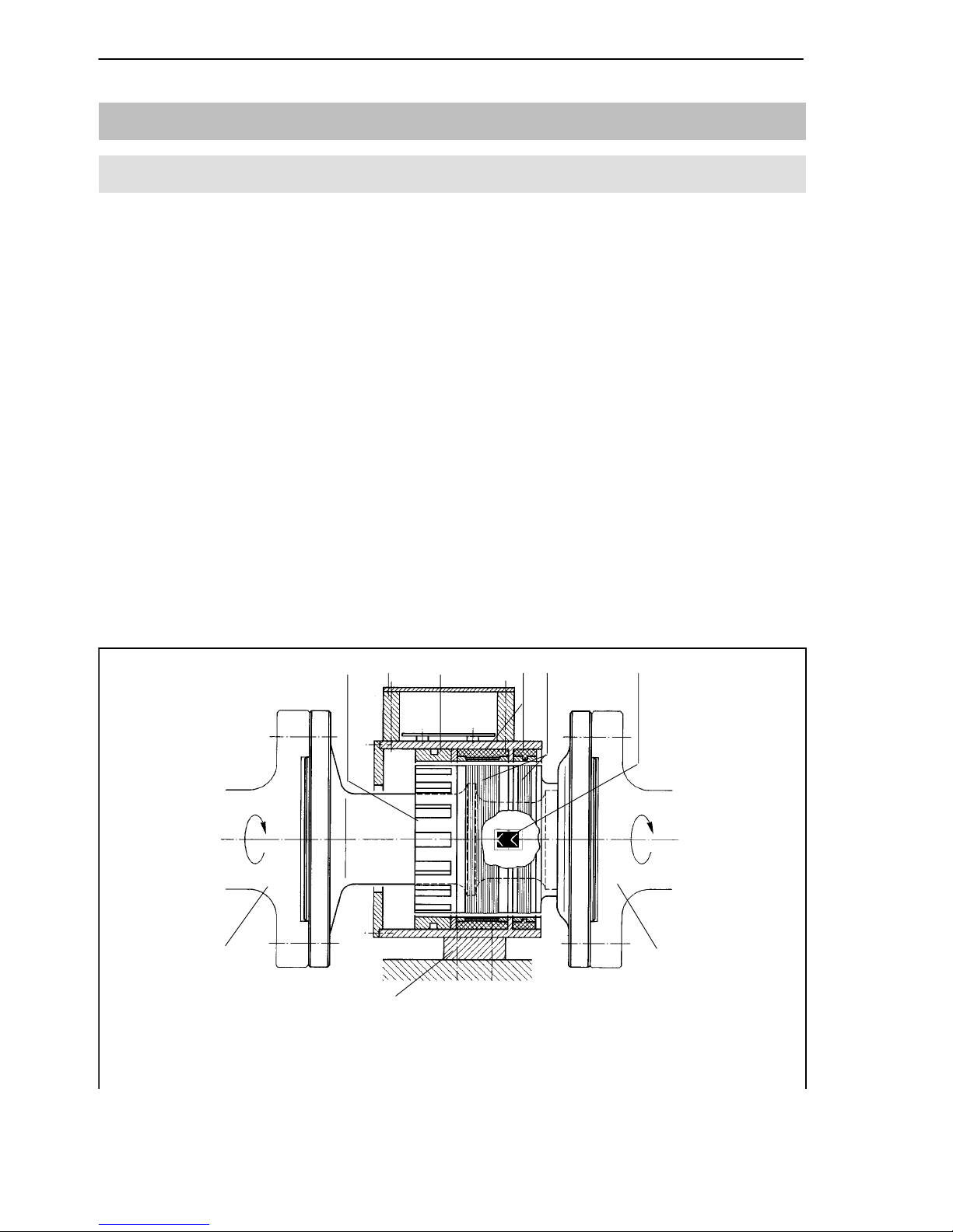
The schematic design of a torque transducer is given in Fig. 2.1. The torque
transducer consists of a measurement body which is screwed to the measurement object by means of two flanges.
The hollow shaft which forms the measurement body is equipped with strain
gauges. Inside the hollow shaft there is the electronic circuitry for the bridge
excitation voltage and for the transmission of the measurement signals. Furthermore, the shaft housing is equipped with 30 teeth for speed measurement
and with transmission elements for the inductive transmission of the supply
voltage onto the measurement body as well as elements for capacitive transmission of measured values from the shaft to the housing of the torque transducer.
The rotor, consisting of the actual measurement body and the two flanges, is
fitted to the housing by two spindle bearings. The housing also contains preamplifiers for the torque signal and for the speed signal, as well as two inductive proximity detectors which serve to detect the speed and the sense of rotation. The housing also carries the connection plugs for the measurement
cables.
1. Toothed wheel (speed measuring system)
5. Inductive voltage transmission (coils)
6. Strain gauge application
2. Connection box
3. Inductive pick--ups
4. Inductive voltage transmission
7. Mounting plate
Flange A Flange B
12 3 45 6
8
8
8. Shaft ends of the object
7
Stator:Rotor:
Fig. 2.1: Mechanical construction
SUNSTAR传感与控制 http://www.sensor-ic.com/ TEL:0755-83376549 FAX:0755-83376182 E-MAIL:szss20@163.com
SUNSTAR自动化 http://www.sensor-ic.com/ TEL: 0755-83376489 FAX:0755-83376182 E-MAIL:szss20@163.com
Page 9

9
T32FNA
Stator and rotor part are not connected by ball bearings. To ensure concentric positioning of the rotor part in the housing three fixing elements are provided at both ends which serve as safeguard during transport and as mounting aid. They enable to adjust the radial and axial play between rotor and
stator part of the torque transducer. After mounting the torque transducer the
fixing elements must be removed.
2.1.1 Torque measurement system
In the torque transducers T32 FNA there are strain gauges for torque measurement mounted on the rotor in the direction of the main stress. They are
connected as a Wheatstone bridge so that only torque will unbalance the
bridge. Temperature effects are also compensated by means of further balancing elements. Additional axial and lateral forces as well as bending moments
within the permitted limits will have only a slight influence (see section ”8.
Technical Data”).
A 15kHz voltage of 54V peak-to-peak for bridge excitation is transmitted by
inductive means. The frequency-to-voltage converter in the rotor forms out of
this a stable bridge excitation voltage. The torque acting on the sensing element deforms it and also the strain gauges. The strain gauges change their
resistance proportional to the strain thus detuning the Wheatstone bridge. The
output voltage of the bridge which is proportional to the torque is then fed to a
voltage-to-frequency converter. This, in turn, produces pulses through integration, the frequency of which is proportional to the bridge output voltage. The
pulses are inductively transmitted to the stator. They are then transformed in a
preamplifier into a pulse frequency of 12V peak-to-peak in the frequency
range from 5kHz to 15kHz. In the no-load state the output signal is 10kHz.
Depending on the sense of the torque the output signal at the ”MD” plug will
be either 15kHz or 5kHz at rated torque.
SUNSTAR传感与控制 http://www.sensor-ic.com/ TEL:0755-83376549 FAX:0755-83376182 E-MAIL:szss20@163.com
SUNSTAR自动化 http://www.sensor-ic.com/ TEL: 0755-83376489 FAX:0755-83376182 E-MAIL:szss20@163.com
Page 10
10
T32FNA
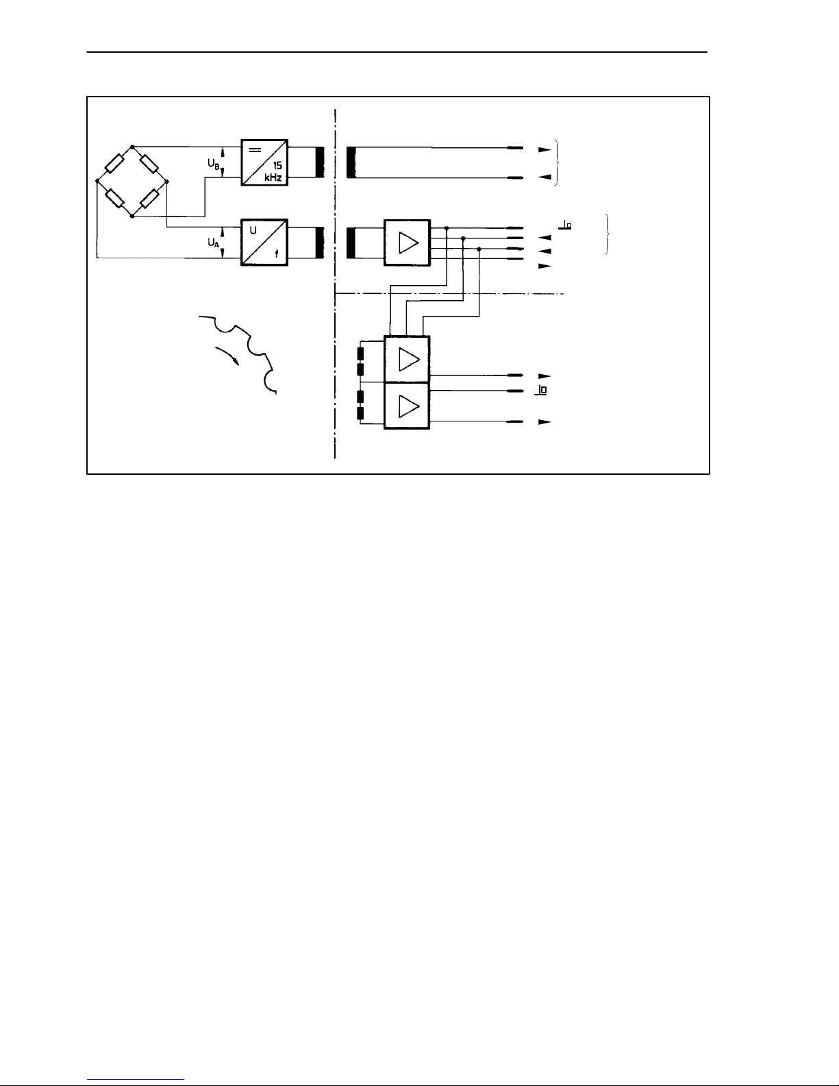
6 Supply voltage
for rotor
7 15kHz, 54V/74V
1
2 --15V
3+15V
4 ”MD”-output signal
5/15kHz.....
4 Speed signal 25 V
1
7 Speed signal 25 V
Rotor Stator
Pre--amplifier
”MD” and ”n”
Plug ”MD”
Plug ”n”
Fig. 2.2: Schematic circuit diagram
2.1.2 Speed measurement system
The rotor carries a toothed wheel with 15 teeth for the determination of speed.
On the stator there are evenly distributed, four inductive pick-ups. During one
revolution of the rotor 15 voltage pulses are produced the frequency of which
is proportional to speed. The pick-ups are displaced in such a way that two
pulse trains appear with a phase shift of 90. The phase shift serves as the information on the sense of rotation of the shaft.
A pre-amplifier serves to transform the two pulse trains into square waves of
25V peak-to-peak. The speed proportional square wave is available at the ”n”
plug for further processing.
Experience has shown that smooth, vibration-free running and a concentric
rotor are essential for accurate measurement of speed.
Vibration is permitted up to a maximum vibration amplitude falling with in-
creasing speed (see Fig. 2.3, Curve A).
If there is static eccentricity of the stator to the rotor, the possible maximum
vibration amplitude displacement (relative vibration displacement is reduced.
Curves B, C and D are examples of this relationship for eccentricities of
0.5 mm, 1 mm and 2 mm.
SUNSTAR传感与控制 http://www.sensor-ic.com/ TEL:0755-83376549 FAX:0755-83376182 E-MAIL:szss20@163.com
SUNSTAR自动化 http://www.sensor-ic.com/ TEL: 0755-83376489 FAX:0755-83376182 E-MAIL:szss20@163.com
Page 11

11
T32FNA
Note: The limit values given for the speed measurement system are not identical to the physical stress limits for the system which can be considerably
lower.
A: Concentric stator and rotor
B: Static eccentricity 0,5 mm
C: Static eccentricity 1,0 mm
D: Static eccentricity 2,0 mm
Relative vibration amplitude (peak--to--peak) in
mm
Speedninrev/min
Fig. 2.3: Maximum permitted vibration amplitude
SUNSTAR传感与控制 http://www.sensor-ic.com/ TEL:0755-83376549 FAX:0755-83376182 E-MAIL:szss20@163.com
SUNSTAR自动化 http://www.sensor-ic.com/ TEL: 0755-83376489 FAX:0755-83376182 E-MAIL:szss20@163.com
Page 12

12
T32FNA
3 Installation
3.1 General hints
- The torque transducers are screwed to the free shaft ends or to the couplings via flanges at both ends. Dimensions of connections see section
”9. Dimensions”.
- Align shaft ends precisely. In order to avoid mechanical overloading HBM
recommend to use couplings at both sides. Thus adverse loadings as
bending moments, lateral and axial forces will be excluded and cannot act
on the torque transducer.
- Stator and rotor are not mechanically connected. The stator should be fixed
to an external support construction by means of the mounting plate.
The support should be designed in such a way that the permitted mechanical tolerances are maintained. Axial and radial displacements with respect
to the rotor should only occur within the specified limits (see Technical
Data)
3.2 Precautions
The torque transducers T32 FNA are protected to IP 54 according to
EN 60 529. Torque transducers shall be protected against coarse dirt particles, dust, oil, solvents and humidity.
3.3 Mounting
The torque transducers T32 FNA may be mounted in a train of shafts without
couplings. However, it is imperative that error loads due to deviations from
plane running, smooth running and concentricity shall have no effect on the
torque transducer. Contact HBM, if details on the permissible radial and angular displacement of the transducers are required.
Since this is very difficult to realise HBM recommend to mount T32 FNA
torque transducers with intermediate couplings e.g. tooth couplings.
SUNSTAR传感与控制 http://www.sensor-ic.com/ TEL:0755-83376549 FAX:0755-83376182 E-MAIL:szss20@163.com
SUNSTAR自动化 http://www.sensor-ic.com/ TEL: 0755-83376489 FAX:0755-83376182 E-MAIL:szss20@163.com
Page 13

13
T32FNA
For the selection of suitable couplings the following criteria should be applied:
- Couplings should be dimensioned in accordance with the torque and speed
hat are expected.
- When estimating the possible loads one should take care of acceleration
and deceleration moments as well as the passing through critical speeds of
rotation. Periodic peaks of torque could be considerably higher than the average calculated from nominal power and speed. If the coupling is overdimensioned as well as the torque transducer this will bring safety against
mechanical overloading.
- Couplings should be selected so that any additional force or moment is
within the ratings, or cannot act on the torque transducer.
- Couplings can be self centering. Angular displacements, parallel and axial
shifts shall be cancelled.
- Mounting surfaces for the connection of the coupling housing shall be clean
and free from grease.
- Stability class and fastening torque for nuts and bolts to be used in the two
connecting flanges:
Nominal
torque
T32 FNA
Cheese-head screw*)as
machined, lubricated
m
tot
= 0.125
Hexagon nut as ma-
chined, lubricated
m
tot
= 0.125
Screws and
nuts per
flange evenly
distributed
Tighten-
ing
torque
50 Nm M 6 x 25 DIN 912-12.9 M 6 DIN 934-12 4 16 Nm
100 Nm M 6 x 25 DIN 912-12.9 M 6 DIN 934-12 4 16 Nm
200 Nm M 6 x 25 DIN 912-12.9 M 6 DIN 934-12 8 16 Nm
500 Nm M 10 x 35 DIN 912-10.9 M 10 DIN 6924-10 5 67 Nm
1kNm M 10 x 35 DIN 912-10.9 M 10 DIN 6924-10 10 67 Nm
2kNm M 10 x 35 DIN 912-10.9 M 10 DIN 6924-10 15 67 Nm
10 kNm M 16 x 50 DIN 912-10.9 M 16 DIN 6924-10 18 290 Nm
25 kNm M16x1.5x50DIN
912-12.9
M16x1.5 DIN
934-12
18 360 Nm
*)
The screw length belongs to the combination T32 FNA-Tacke GLB-Curved Tooth CouplingsÊ
The information given above applies under the following conditions:
Surface condition of the flanges in the area of the friction fit surfaces and of the contact surface of scre-
whead or nuts R
A
3.2mm.
Flange material: steel, tensile strength
900N/mm
2
.
SUNSTAR传感与控制 http://www.sensor-ic.com/ TEL:0755-83376549 FAX:0755-83376182 E-MAIL:szss20@163.com
SUNSTAR自动化 http://www.sensor-ic.com/ TEL: 0755-83376489 FAX:0755-83376182 E-MAIL:szss20@163.com
Page 14

14
T32FNA
Arrangement of the screws [-] on t he flange:
T32 FNA 50Nm ... 200Nm
T32 FNA 500Nm ... 2 kNm
T32 FNA 10 kNm ... 25 kNm
3.3.1 Mounting with curved tooth couplings
Selfcentering curved tooth couplings made by Messrs. Tacke are proved in
combination with HBM torque transducers. They are torsionally stiff and take
care of the introduction even of dynamic torque to the torque transducer in the
correct way. In addition, angular displacement and parallel or axial shift are
compensated with small restoring force.
HBM can supply suitable couplings that are well matched to the type of torque
transducer and the intended use. Special requirements of the customer are
taken care of and the shaft connections are made to the specified dimensions.
The torque transducer and the coupling housing are assembled at HBM and
are dynamically balanced (balancing quality level G 2.5). Therefore, the
mounted assembly should not be disassembled again. If this cannot be
avoided one should mark all parts in such a way that they can be assembled
afterwards in exactly the same way. Upon reassembly, the original balancing
quality can only be obtained by renewed balancing.
Coupling hubs are balanced individually and the keyways are made after balancing. Further information will be found in the various data sheets provided
by HBM.
SUNSTAR传感与控制 http://www.sensor-ic.com/ TEL:0755-83376549 FAX:0755-83376182 E-MAIL:szss20@163.com
SUNSTAR自动化 http://www.sensor-ic.com/ TEL: 0755-83376489 FAX:0755-83376182 E-MAIL:szss20@163.com
Page 15

15
T32FNA
3.4 Fixing of the housing
The stator housing is fitted around the rotor without bearings or without any
mechanical connection. When delivered there are fixing elements at the sides
of the stator that serve as safeguard during transport and as mounting aid for
radial and axial positioning and ensure that stator and rotor axes are properly
aligned.
Important:
- The fixing elements must be screwed in during mounting and dismounting,
and during transportation of the torque transducer. This prevents any damage to the signal transmitting devices on the stator and rotor.
- During operation fixing elements must be removed!
Follow these points when mounting:
(see section ”9. Dimensions”)
- The T32 FNA shall be mounted in the train of shafts as delivered so that
the mounting plane of the stator is seated on the prepared support plane
without play or stress. The two connection flanges shall be connected to
the shaft ends or couplings respectively.
- Any possible height difference shall be adjusted by shims. Screw in fixing
screws; do not yet t ighten to avoid jamming of the fixing elements.
- Mark position of the stator or adjust respective stops.
- Remove fixing elements from the torque transducer.
- Check dimension Z (see section ”9. Dimensions”).
- Tighten fixing screws. Stator must stay in marked position or at stops. Ro-
tor must rotate freely.
- Check if radial and axial tolerances are kept.
- Check smooth running of the torque transducer, beginning with low speeds.
In the case of elastically suspended machines larger radial and axial movements may occur. If the occurring movements exceed the permitted limits of
2.5mm, or 3mm resp. one must take care that the stator can follow the motions of the rotor, or the motions shall be properly decoupled.
If couplings are mounted a possible axial and radial play should be considered as well.
SUNSTAR传感与控制 http://www.sensor-ic.com/ TEL:0755-83376549 FAX:0755-83376182 E-MAIL:szss20@163.com
SUNSTAR自动化 http://www.sensor-ic.com/ TEL: 0755-83376489 FAX:0755-83376182 E-MAIL:szss20@163.com
Page 16

16
T32FNA
3.5 Mounting position
The T32 FNA can be mounted in any position. If mounted with couplings the
relevant restrictions of the couplings shall be observed regarding slanted or
vertical operation.
For the determination of the sense of rotation the following holds:
An arrow is marked on the stator for the unambiguous determination of the
sense of rotation. If the torque transducer rotates in the direction of the ar-
row the connected amplifier outputs a positive signal (0...+10 V).
For the determination of the sense of the torque the following holds:
If clockwise torque is applied the output frequency is 10...15 kHz. In conjunction with HBM amplifiers there will be a positive output signal (0...+10 V).
Fig. 3.1: Direction of torque
SUNSTAR传感与控制 http://www.sensor-ic.com/ TEL:0755-83376549 FAX:0755-83376182 E-MAIL:szss20@163.com
SUNSTAR自动化 http://www.sensor-ic.com/ TEL: 0755-83376489 FAX:0755-83376182 E-MAIL:szss20@163.com
Page 17

17
T32FNA
3.6 Limits of application
The nominal speed of the torque transducer is given on the type plate. It refers to the permitted continuous speed of the torque transducer when installed
and represents the maximum load due to the kinetic energy of rotation that
the transducer can tolerate.
Practical experience has shown that the running smoothness of the torque
transducers is very dependent on the overall construction of the testbed.
Thus, vibration can occur whose amplitude may be influenced by the mass of
the resonating housing and foundation, the stiffness of the bearings or supports and the proximity of resonance. Since HBM can have no responsibility
for such factors, diagram 1 shows the stated limit values of maximum deflection of the relative shaft vibration s
max
in relation to the speed for T32 FNA
torque transducers.
- Transducers without couplings
- The maximum speed is the nominal speed given on the type plate.
- The torque transducer supplied has been tested on a testbed and fulfils the
requirements of diagram.
- Transducers with couplings
- With GLB couplings: nominal speed as for torque transducer according to
diagram 1.
- With SBG couplings: the maximum speed is the lower rated speed of the
couplings being used (see section ”8. Technical Data”)
- The vibration characteristics of the combined torque transducer and coupling supplied by HBM have been tested on a testbed and fulfil the requirements of diagram 1.
SUNSTAR传感与控制 http://www.sensor-ic.com/ TEL:0755-83376549 FAX:0755-83376182 E-MAIL:szss20@163.com
SUNSTAR自动化 http://www.sensor-ic.com/ TEL: 0755-83376489 FAX:0755-83376182 E-MAIL:szss20@163.com
Page 18

18
T32FNA
In the diagram shown, the maximum permitted vibration amplitude s is plotted
against the speed.
The maximum values must not be exceeded during normal operation. They refer only to the
T32 FNA torque transducer and not to any connected machinery. s
max
is defined accordingly
to DIN 45670 and VDI 2059.
Speed in rev/min
m mMax. vibration amplitude in
Measuring planes
Diagram 1: Vibration amplitude versus the speed
Using a T32 FNA torque transducer in conjunction with SBG curved-tooth
couplings allows the advantages of the T32 FNA to be utilized for low speeds
in combination with cheap couplings. In this combination the continuous
speeds are lower than with the GLB curved-tooth couplings normally used.
SUNSTAR传感与控制 http://www.sensor-ic.com/ TEL:0755-83376549 FAX:0755-83376182 E-MAIL:szss20@163.com
SUNSTAR自动化 http://www.sensor-ic.com/ TEL: 0755-83376489 FAX:0755-83376182 E-MAIL:szss20@163.com
Page 19

19
T32FNA
4 Electrical connections
4.1 Connection plugs and cables
The type T32 FN / T32 FNA torque transducers differ only in the type of connector:
T32FN MS 3102A16S--1P............
T32FNA Binder 423...........
The two 7-pole instrument plugs Binder 423 (MS 3102 A 1 6S--1 P for
T32 FN) mounted at the housing are marked ”MD” for the torque signal and
”n” for the speed signal.
1 Operating voltage zero <WH>
Plug MD
2 Preamplifier supply voltage (--15V) <BK>
g
3 Preamplifier supply voltage (+15V) <BU>
61
4 Torque output signal (12Vpp; 5...15kHz) <RD>
5 72
43
5 Not connected
4
3
6 Rotor supply voltage (54V/74Vpp; 15kHz) <GN>
7 Rotor supply voltage (0V) <GY>
1 Operating voltage zero <WH>
Pl
u
g
n
2 Not connected
P
lug
n
3 Not connected
4 Rotation rate signal (25Vpp; 15 pulses/revolution) <RD>
61
5 72
5 Not connected
43
6 Not connected
7
Rotation rate signal (25Vpp; 15 puls./rev.);
phase shifted by 90 <GY>
The lead screen is laid flat on the connector case. This means that the complete measurement system is enclosed in a Faraday cage, reducing any electromagnetic interference.
With interference caused by potential differences (equalisation currents) the
system zero-voltage and the housing ground should be isolated from one
another and a potential equalisation conductor located between the housings
of the transducer and the amplifier (flexible stranded wire, 10 mm
2
conductor
cross-section).
SUNSTAR传感与控制 http://www.sensor-ic.com/ TEL:0755-83376549 FAX:0755-83376182 E-MAIL:szss20@163.com
SUNSTAR自动化 http://www.sensor-ic.com/ TEL: 0755-83376489 FAX:0755-83376182 E-MAIL:szss20@163.com
Page 20

20
T32FNA
4.2 Instruments that can be connected
The basic requirements for the trouble-free operation of torque transducers
are:
- Adequate power supply for the non-contact telemetry
- Supply for the preamplifier built into the transducer
HBM has various amplifiers available for numerous applications and these
can supply the transducers and process the torque and torque-proportional
signals. The connection details can be found in the operating manual for the
relevant electronic measurement system.
5 Calibration signal
The torque transducers T32 FNA deliver an additive electrical calibration signal that can be called from the amplifier.
When pressing a push button on the front panel of the amplifier the supply
voltage is increased from 54V to 74V. The torque transducer responds with
the output of a calibration signal of approximately 12.5kHz
50% of the rated
torque. The precise value is given on the nameplate of the T32 FNA. The amplifier has to be adjusted to the precise calibration signal of the connected unloaded torque transducer in order to achieve calibration of the measurement
chain.
SUNSTAR传感与控制 http://www.sensor-ic.com/ TEL:0755-83376549 FAX:0755-83376182 E-MAIL:szss20@163.com
SUNSTAR自动化 http://www.sensor-ic.com/ TEL: 0755-83376489 FAX:0755-83376182 E-MAIL:szss20@163.com
Page 21

21
T32FNA
6 Load limits
The nominal torques may be exceeded statically by max. 50 %. Within the
nominal torque exceeded, no additional irregular loads such as longitudinal
and transverse forces and bending moments are permissible. The limit values
are specified in the chapter ”8. Technical Data”.
Measurement of static and dynamic torque
Torque transducers T32 FNA are suitable for the measurement of static and
dynamic torques. When dynamic torque is measured one should note the following:
- The static calibration of the T32 FNA is also valid for dynamic torque measurements.
Note: The frequency of dynamic torque must not exceed the natural frequency of the mechanical measuring installation.
- The natural frequency f
o
of the mechanical measuring installation depends
on the moments of inertia J
1
and J2of the coupled rotating masses and de-
pends on the torsional stiffness c
T
of the T32 FNA.
The natural frequency of the arrangement can be calculated with the following
equation:
f
0
1
2
·cT·
Æ
1
J
1
1
J
2
É
¯
f
0
= natural frequency of the
measurement arrangement (Hz)
J
1,J2
= mass moment of inertia of
the connected rotating masses (kgm
2
)
c
T
= torsional stiffness of the torque
transducer (Nm/rad)
SUNSTAR传感与控制 http://www.sensor-ic.com/ TEL:0755-83376549 FAX:0755-83376182 E-MAIL:szss20@163.com
SUNSTAR自动化 http://www.sensor-ic.com/ TEL: 0755-83376489 FAX:0755-83376182 E-MAIL:szss20@163.com
Page 22

22
T32FNA
- The amplitudes (peak-to-peak) must never exceed 70 % of the nominal
torque for the specific type, even with oscillating torque. In all cases the
amplitudes must lie within the load range limits of -- M
N
and + MN.
+MN100
-M
N
100
50
50
0
45
25
70% M
N
Range
Nominal torque MNin %
Upper torque limit
Lower torque limit
Fig. 6.1: Amplitudes of dynamic torque
7 Maintenance
Torque transducers type T32 FNA are maintenance-free owing to their design
without bearings and with non-contacting transfer of the energising voltages
and of the measured signal.
SUNSTAR传感与控制 http://www.sensor-ic.com/ TEL:0755-83376549 FAX:0755-83376182 E-MAIL:szss20@163.com
SUNSTAR自动化 http://www.sensor-ic.com/ TEL: 0755-83376489 FAX:0755-83376182 E-MAIL:szss20@163.com
Page 23

23
T32FNA
8 Technical Data
Accuracy class 0.3 0.2 0.1
Torque measuring system
Nominal torque M
N
Nm
kNm
50 100 200 500
1 2 10 25
Measuring system
Excitation voltage -- and measuring signal
transmission
strain gauge full bridge
Inductive
Excitation voltage
Square-wave voltage (peak-to-peak)
Current consumption
Frequency
V
mA
kHz
54 5%
800 5%
approx. 15
Voltage for preamplifier V -15/0/+15
Preamplifier, max. current consumption mA -20/0/+20
Calibration signal, value given on name
plate
approx. 50 % von M
N
Tolerance of calibration signal
relatedtoM
N
% < 0,05
Release of calibration signal
Current consumption
V
mA
80 5%
1000 5%
Torque output signal pulse train
Nominal torque output signal
with positive M
N
with negative M
N
Load resistance
kHz
kHz
kW
15 (12V peak-to-peak)
5 (12V peak-to-peak)
2
Nominal sensitivity (nominal signal span
between torque = zero and nominal torque)
kHz 5
Sensitivity tolerance (deviation of the actual signal span to the nominal signal span at
M
N
) % < 0.1
Temperature error per 10 K at nominal temperature range of
output signal, related to the actual value
of signal span
% < 0.1
zero signal, related to the nominal sensitivity
% < 0.1 < 0.05
Linearity deviation including hysteresis,
related to the nominal sensitivity
% <0.3 < 0.2 < 0.1
Relative standard deviation of the reproducibility according to DIN 1319
% < 0.03
SUNSTAR传感与控制 http://www.sensor-ic.com/ TEL:0755-83376549 FAX:0755-83376182 E-MAIL:szss20@163.com
SUNSTAR自动化 http://www.sensor-ic.com/ TEL: 0755-83376489 FAX:0755-83376182 E-MAIL:szss20@163.com
Page 24

24
T32FNA
Speed measuring system
Nominal torque Nm
kNm
50 100 200 500
1 2 10 25
Measuring system brushless, inductive
Output signal for speed pulse train
Pulse voltage (peak-to-peak)
between plug contacts 1 and 4
between plug contacts 7 and 1
Load resistance
V
kW
25
15 pulses per revolution
15 pulses per revolution, displaced by 90
5
Minimum speed min
-- 1
2
Mechanical Data
Nominal temperature range C +10...+60
Service temperature range C -- 10 ... + 60
Storage temperature range C -- 50 ... + 70
Load limits
Torque limit, related to M
N
Destruction torque, related to M
N
%
%
150
> 300
Lateral limit force
1)
Axial limit force
1)
Bending limit moment
1)
N
kN
Nm
50
1.3
6
100
2.5
12
190
5
23
410
7
60
1.1k
14
115
1.6k
27
230
5.7k
100
1 150
14k
200
2.8k
Vibration amplitude to DIN 50 100 (peakto-peak)
Nm 35 70 140 350 700 1.4k 7k 17.5k
Mechanical impact test2)degree of preci-
sion according to IEC 68-2-27-1987
Number
Duration
Acceleration
n
ms
m/s
2
1000
3
500
Vibration stressing test2), degree of precision according to IEC 68-2-6-1985
Frequency range
Duration
Acceleration
Hz
h
m/s
2
5-65
1.5
50
Torsional stiffness c
T
kNm/rad 10.5 19.5 34.3 142 242 369 2910 6480
Torsion angle at M
N
grad 0.27 0.29 0.33 0.2 0.24 0.31 0.19 0.22
Mass moment of inertia (axially) gm
2
1.85 16 149 154
Nominal speed (without coupling) min--1 20 000 15 000 11 000
Nominal speed3)with
SBG-Coupling min
-- 1
3000
GLB-Coupling min
-- 1
20 000 15 000 10000 7600
1) Each type of irregular stress can only be permitted with its given limit value (bending moment, side load or
axial load, exceeding the nominal speed) if none of the others can occur. Otherwise the limit values must
be reduced. If for instance 30% of the bending moment and also 30% of the side load are present, only
40% of the axial load are permitted, provided that the nominal torque is not exceeded. With maximum additional loading, measuring errors of the order of 1% of the nominal torque can occur.
2) The technical data did not change after impact and vibrational stressing test.
3) The maximum permissible continuous speed for the T32 FNA-coupling mounted and balanced by HBM
given on the plate.
SUNSTAR传感与控制 http://www.sensor-ic.com/ TEL:0755-83376549 FAX:0755-83376182 E-MAIL:szss20@163.com
SUNSTAR自动化 http://www.sensor-ic.com/ TEL: 0755-83376489 FAX:0755-83376182 E-MAIL:szss20@163.com
Page 25

25
T32FNA
Nominal torque Nm
kNm
50 100 200 500
1 2 10 25
Quality grade4)according to VDI 2060 G2.5
Permissible residual unbalance per unit
weight of inertial body per plane
gnm/kg 0.5 0.7 0.8
Weight
Rotor kg 2.5 7.1 7.2 7.3 31.6 32
Stator kg 2.8 3 11
Total kg 5.3 10.1 10.2 10.3 42.6 43
Protection class accordingtoEN60529 IP 54
Maximum permissible static eccentricity of
the rotor (radially)
(centering with fixing elements)
mm 2.5 2.0 3
Maximum permissible amplitude (peak-topeak) of the rotor
with speed measurement
with torque measurement
mm
mm
2.5
5)
5
Permissibleaxial displacement between
shaft and housing
(centering with fixing elements)
mm 3
4) The balance quality grades include the coupling housing if it has been mounted on the shaft by HBM.
5) Accurate measurement of speed depends on the relation between the static eccentricity and the maximum
vibration amplitude of the rotor (see para. ”2.1.2 Speed measurement system”).
SUNSTAR传感与控制 http://www.sensor-ic.com/ TEL:0755-83376549 FAX:0755-83376182 E-MAIL:szss20@163.com
SUNSTAR自动化 http://www.sensor-ic.com/ TEL: 0755-83376489 FAX:0755-83376182 E-MAIL:szss20@163.com
Page 26

26
T32FNA
9 Dimensions
Flange A Flange B
Plug for speed
measuring signal
and indication of
direction
Plug for torque
measuring signal
Permissible deviation
of pitch5’
Dimensions without tolerances to DIN 7168-m
Transport locking
device and
mounting accessory
Type plate
Mounting surface
Z
Nominal
Dimensions in mm
torque
A B
--0.005
C D E F
0,1
G H J K L M N
50 to 200Nm 90 60 84 70 107 72 6 8.5 15 38 76 M5 8
500Nm to 2kNm 157
0.2
100 102 80 124 130 17 13 22 38 90.5 M8 12
10 to 25 kNm 235 140 122 80 216 196 33.5 18.5 60 80 90 M8 14
Nominal
Dimensions in mm
torque
O
-- 0. 5P-- 0. 2
Q R S T
H12
U V W X Y Z
50 to 200Nm 161.5 66.5 87.5 105 69 6.4 70 30 45 8x45 58.8 28
500Nm to 2kNm 171.5 75 96 105 69 10.5 70 54 24 15x24 67 17
10 to 25 kNm 244.6 123 140.8 105 69 17 130 110 20 18x20 113 42.6
SUNSTAR传感与控制 http://www.sensor-ic.com/ TEL:0755-83376549 FAX:0755-83376182 E-MAIL:szss20@163.com
SUNSTAR自动化 http://www.sensor-ic.com/ TEL: 0755-83376489 FAX:0755-83376182 E-MAIL:szss20@163.com
Page 27

27
T32FNA
10 Copy of Declaration of Conformity
SUNSTAR传感与控制 http://www.sensor-ic.com/ TEL:0755-83376549 FAX:0755-83376182 E-MAIL:szss20@163.com
SUNSTAR自动化 http://www.sensor-ic.com/ TEL: 0755-83376489 FAX:0755-83376182 E-MAIL:szss20@163.com
Page 28

28
T32FNA
SUNSTAR传感与控制 http://www.sensor-ic.com/ TEL:0755-83376549 FAX:0755-83376182 E-MAIL:szss20@163.com
SUNSTAR自动化 http://www.sensor-ic.com/ TEL: 0755-83376489 FAX:0755-83376182 E-MAIL:szss20@163.com
Page 29

29
T32FNA
SUNSTAR传感与控制 http://www.sensor-ic.com/ TEL:0755-83376549 FAX:0755-83376182 E-MAIL:szss20@163.com
SUNSTAR自动化 http://www.sensor-ic.com/ TEL: 0755-83376489 FAX:0755-83376182 E-MAIL:szss20@163.com
Page 30

30
T32FNA
SUNSTAR传感与控制 http://www.sensor-ic.com/ TEL:0755-83376549 FAX:0755-83376182 E-MAIL:szss20@163.com
SUNSTAR自动化 http://www.sensor-ic.com/ TEL: 0755-83376489 FAX:0755-83376182 E-MAIL:szss20@163.com
Page 31

31
T32FNA
SUNSTAR传感与控制 http://www.sensor-ic.com/ TEL:0755-83376549 FAX:0755-83376182 E-MAIL:szss20@163.com
SUNSTAR自动化 http://www.sensor-ic.com/ TEL: 0755-83376489 FAX:0755-83376182 E-MAIL:szss20@163.com
Page 32

HOTTINGER BALDWIN MESSTECHNIK
HBM Mess- und Systemtechnik GmbH
Postfach 10 01 51, D-64201 Darmstadt
Im Tiefen See 45, D-64293 Darmstadt
Tel.: +49/ 61 51/ 8 03-0; Fax: 89 48 96;
www.hbm.de
Modifications reserved.
All details describe our products in general
form only.They are not to be understood as
express warranty and do not constituteany
liability whatsoever.
IM--D 10.98 -- POD
SUNSTAR传感与控制 http://www.sensor-ic.com/ TEL:0755-83376549 FAX:0755-83376182 E-MAIL:szss20@163.com
SUNSTAR自动化 http://www.sensor-ic.com/ TEL: 0755-83376489 FAX:0755-83376182 E-MAIL:szss20@163.com
 Loading...