

Page 1
Mounting Instructions
Digital
Torque Transducer
T12
A1979-7.1 en
Page 2

Page 3

T12
3
Contents Page
Contents
Safety instructions 5. . . . . . . . . . . . . . . . . . . . . . . . . . . . . . . . . . . . . . . . . . . . . .
1 Scope of supply 9. . . . . . . . . . . . . . . . . . . . . . . . . . . . . . . . . . . . . . . . . . . . .
2 Operation 9. . . . . . . . . . . . . . . . . . . . . . . . . . . . . . . . . . . . . . . . . . . . . . . . . . .
3 Application 10. . . . . . . . . . . . . . . . . . . . . . . . . . . . . . . . . . . . . . . . . . . . . . . . . .
4 Signal flow 11. . . . . . . . . . . . . . . . . . . . . . . . . . . . . . . . . . . . . . . . . . . . . . . . . .
5 Structure and mode of operation 13. . . . . . . . . . . . . . . . . . . . . . . . . . . . . .
6 Mechanical installation 14. . . . . . . . . . . . . . . . . . . . . . . . . . . . . . . . . . . . . . .
6.1 Conditions on site 14. . . . . . . . . . . . . . . . . . . . . . . . . . . . . . . . . . . . . . . .
6.2 Mounting position 15. . . . . . . . . . . . . . . . . . . . . . . . . . . . . . . . . . . . . . . .
6.3 Installing the slotted disc (speed measuring system only) 15. . . . . .
6.4 Installing the rotor 16. . . . . . . . . . . . . . . . . . . . . . . . . . . . . . . . . . . . . . . .
6.5 Fitting the protection against contact (option) 19. . . . . . . . . . . . . . . .
6.6 Installing the stator 25. . . . . . . . . . . . . . . . . . . . . . . . . . . . . . . . . . . . . . .
6.6.1 Preparing with the mounting kit (included among the items
supplied) 26. . . . . . . . . . . . . . . . . . . . . . . . . . . . . . . . . . . . . . . . . .
6.6.2 Aligning the stator 28. . . . . . . . . . . . . . . . . . . . . . . . . . . . . . . . . .
6.6.3 Stator installation over the protection against contact
(option) 30. . . . . . . . . . . . . . . . . . . . . . . . . . . . . . . . . . . . . . . . . . .
6.7 Optical speed/angle of rotation measuring system (option) 31. . . . .
Axial alignment 32. . . . . . . . . . . . . . . . . . . . . . . . . . . . . . . . . . . . . . . . . .
Radial alignment 32. . . . . . . . . . . . . . . . . . . . . . . . . . . . . . . . . . . . . . . . .
7 LED status display 34. . . . . . . . . . . . . . . . . . . . . . . . . . . . . . . . . . . . . . . . . . .
7.1 Measuring mode operation 34. . . . . . . . . . . . . . . . . . . . . . . . . . . . . . . .
7.2 Rotor clearance setting mode operation 34. . . . . . . . . . . . . . . . . . . . .
7.3 Speed measuring system setting mode operation 34. . . . . . . . . . . .
8 Electrical connection 35. . . . . . . . . . . . . . . . . . . . . . . . . . . . . . . . . . . . . . . . .
8.1 General hints 35. . . . . . . . . . . . . . . . . . . . . . . . . . . . . . . . . . . . . . . . . . . .
8.2 Shielding design 35. . . . . . . . . . . . . . . . . . . . . . . . . . . . . . . . . . . . . . . . .
8.3 Connector pin assignment 36. . . . . . . . . . . . . . . . . . . . . . . . . . . . . . . .
8.4 Supply voltage 40. . . . . . . . . . . . . . . . . . . . . . . . . . . . . . . . . . . . . . . . . .
8.4.1 Supply voltage for self‐contained operation 40. . . . . . . . . . . .
9 Shunt signal 41. . . . . . . . . . . . . . . . . . . . . . . . . . . . . . . . . . . . . . . . . . . . . . . . .
A1979-7.1 en HBM
Page 4

4
10 Loading capacity 42. . . . . . . . . . . . . . . . . . . . . . . . . . . . . . . . . . . . . . . . . . . . .
10.1 Measuring dynamic torque 42. . . . . . . . . . . . . . . . . . . . . . . . . . . . . . . .
11 TEDS 43. . . . . . . . . . . . . . . . . . . . . . . . . . . . . . . . . . . . . . . . . . . . . . . . . . . . . . .
11.1 Content of the TEDS memory as defined in IEEE 1451.4 44. . . . . .
12 Maintenance 50. . . . . . . . . . . . . . . . . . . . . . . . . . . . . . . . . . . . . . . . . . . . . . . . .
12.1 Cleaning the speed measuring system 50. . . . . . . . . . . . . . . . . . . . . .
13 Specifications 51. . . . . . . . . . . . . . . . . . . . . . . . . . . . . . . . . . . . . . . . . . . . . . .
14 Dimensions 61. . . . . . . . . . . . . . . . . . . . . . . . . . . . . . . . . . . . . . . . . . . . . . . . .
14.1 Rotor dimensions 61. . . . . . . . . . . . . . . . . . . . . . . . . . . . . . . . . . . . . . . .
T12
14.2 Stator dimensions 100 N
system (in mm) 62. . . . . . . . . . . . . . . . . . . . . . . . . . . . . . . . . . . . . . . . . .
14.3 Stator dimensions 100 N
system (in mm) 63. . . . . . . . . . . . . . . . . . . . . . . . . . . . . . . . . . . . . . . . . .
14.4 Stator dimensions 100 N
system (in mm) 64. . . . . . . . . . . . . . . . . . . . . . . . . . . . . . . . . . . . . . . . . .
14.5 Stator dimensions 100 N
contact (in mm) 65. . . . . . . . . . . . . . . . . . . . . . . . . . . . . . . . . . . . . . . . . .
14.6 Stator dimensions 100 N
contact (in mm) 66. . . . . . . . . . . . . . . . . . . . . . . . . . . . . . . . . . . . . . . . . .
14.7 Stator dimensions 500 N
contact (in mm) 67. . . . . . . . . . . . . . . . . . . . . . . . . . . . . . . . . . . . . . . . . .
14.8 Stator dimensions 2 kN
⋅m ... 10 kN⋅m with protection against
contact (in mm) 68. . . . . . . . . . . . . . . . . . . . . . . . . . . . . . . . . . . . . . . . . .
14.8.1 Dimensions cover plates 100 N
⋅m ... 200 N⋅m with speed measuring
⋅m ... 200 N⋅m with speed measuring
⋅m ... 10 kN⋅m with speed measuring
Vm ... 200 NVm with protection against
Vm ... 200 NVm with protection against
Vm ... 1 kNVm with protection against
⋅m ... 200 kN⋅m69. . . . . . . . .
14.8.2 Dimensions cover plates 500 N
⋅m ... 10 kN⋅m70. . . . . . . . . .
14.9 Mounting dimensions 70. . . . . . . . . . . . . . . . . . . . . . . . . . . . . . . . . . . . .
15 Additional technical information 71. . . . . . . . . . . . . . . . . . . . . . . . . . . . . .
15.1 Radial and axial run‐out tolerances 71. . . . . . . . . . . . . . . . . . . . . . . . .
16 Delivery status 72. . . . . . . . . . . . . . . . . . . . . . . . . . . . . . . . . . . . . . . . . . . . . . .
17 Order numbers 76. . . . . . . . . . . . . . . . . . . . . . . . . . . . . . . . . . . . . . . . . . . . . .
18 Accessories 77. . . . . . . . . . . . . . . . . . . . . . . . . . . . . . . . . . . . . . . . . . . . . . . . .
A1979-7.1 enHBM
Page 5

T12
5
Safety instructions
Use in accordance with the regulations
The T12 digital torque transducer is used exclusively for torque, rotational
speed, angle of rotation and power measurement tasks and control and
adjustment tasks directly connected thereto. Use for any additional purpose
shall be deemed to be not in accordance with the regulations.
Stator operation is only permitted with an installed rotor.
In the interests of safety, the transducer should only be operated as described
in the operating manual. It is also essential to observe the appropriate legal
and safety regulations for the application concerned during use. The same
applies to the use of accessories.
Each time, before starting up the transducer, you must first run a project plan
ning and risk analysis that takes into account all the safety aspects of automa
tion technology. This particularly concerns personal and machine protection.
The transducer is not a safety element within the meaning of its use as
intended. Proper and safe operation of these transducers require proper
transportation, correct storage, assembly and mounting and careful operation.
This is a Class A product. In a domestic environment this product may cause
radio interference in which case the user may be required to take adequate
measures.
General dangers of failing to follow the safety instructions
The transducer corresponds to the state of the art and is fail‐safe. The
transducer can give rise to remaining dangers if it is inappropriately installed
and operated by untrained personnel.
Everyone involved with the installation, commissioning, maintenance or repair
of the transducer must have read and understood the operating manual and in
particular the technical safety instructions.
Remaining dangers
The scope of supply and performance of the transducer covers only a small
area of torque measurement technology. In addition, equipment planners,
installers and operators should plan, implement and respond to the safety
engineering considerations of torque measurement technology in such a way
as to minimize remaining dangers. Prevailing regulations must be complied
with at all times. Reference must be made to remaining dangers connected
with torque measurement technology.
A1979-7.1 en HBM
Page 6
6
In this Mounting instructions remaining dangers are pointed out using the
following symbols:
T12
Symbol:
Meaning: Maximum danger level
Warns of an imminently dangerous situation in which failure to comply with
safety requirements will result in death or serious physical injury.
Symbol:
Meaning: Potentially dangerous situation
Warns of a potentially dangerous situation in which failure to comply with
safety requirements can result in death or serious physical injury.
Symbol:
DANGER
WARNING
CAUTION
Meaning: Dangerous situation
Warns of a potentially dangerous situation in which failure to comply with
safety requirements could result in damage to property or some form of
physical injury.
Symbols for using advices and helpful information:
Symbol:
Means that important information about the product or its handling is being
given.
Symbol:
Meaning: CE mark
NOTE
The CE mark enables the manufacturer to guarantee that the product com
plies with the requirements of the relevant EC directives (the declaration of
conformity is available at http://www.hbm.com/HBMdoc).
A1979-7.1 enHBM
Page 7

T12
7
Symbol:
Meaning: Statutory marking requirements for waste disposal
National and local regulations regarding the protection of the environment and
recycling of raw materials require old equipment to be separated from regular
domestic waste for disposal.
For more detailed information on disposal, please contact the local authorities
or the dealer from whom you purchased the product.
Conversions and modifications
The transducer must not be modified from the design or safety engineering
point of view except with our express agreement. Any modification shall
exclude all liability on our part for any damage resulting therefrom.
Qualified personnel
The transducer must only be installed and used by qualified personnel, strictly
in accordance with the specifications and with safety requirements and
regulations. It is also essential to observe the appropriate legal and safety
regulations for the application concerned during use. The same applies to the
use of accessories.
Qualified personnel means persons entrusted with the installation, fitting,
commissioning and operation of the product who possess the appropriate
qualifications for their function.
Prevention of accidents
According to the prevailing accident prevention regulations, once the T12
digital torque transducer has been mounted, a cover or cladding has to be
fitted as follows:
• The cover or cladding must not be free to rotate.
• The cover or cladding should avoid squeezing or shearing and provide
protection against parts that might come loose.
• Covers and cladding must be positioned at a suitable distance or so
arranged that there is no access to any moving parts within.
• Covers and cladding must also be attached if the moving parts of the
torque flange are installed outside peoples' movement and operating
range.
A1979-7.1 en HBM
Page 8

8
T12
CAUTION
The protection against contact option, to prevent accidental contact,
must not be used as protection against bursting parts.
The only permitted exceptions to the above requirements are if the various
parts and assemblies of the machine are already fully protected by the design
of the machine or by existing safety precautions.
Warranty
In the case of complaints, a warranty can only be given if the torque
transducer is returned in the original packaging.
A1979-7.1 enHBM
Page 9

T12
1 Scope of supply
• Digital torque transducer (rotor and stator)
• T12 Mounting Instructions
• Quick Start Guide for installing the T12 Assistant control software
• T12 system CD
• Mounting kit
• Test report
• Options:
- Speed measuring system, comprising optical rotational speed sensor and
speed kit (slotted disc, screwdriver, screw locking device, screws)
- Protection against contact
- Mounted coupling
9
2 Operation
The supplied T12 system CD contains the "T12 Assistant" control software.
You can use this software to:
• monitor the correct installation of the torque transducer
• set the signal conditioning (zero balance, filters, scaling)
• protect your settings or load the factory settings
• display and evaluate the measured values
Notes on installing the T12 Assistant on your PC can be found in the "T12
Assistant Control Software" Quick Start Guide. (pdf file on T12 system CD
and part of the “Setup Toolkit for T12" accessory).
Notes on the operation of the T12 Assistant can be found in the program's
online Help, which is called with function key F1 or via the menu bar.
For more information about connecting to fieldbus systems, please refer to the
“T12‐CAN bus/PROFIBUS" operating manual (pdf file on T12 system CD).
A1979-7.1 en HBM
Page 10

10
T12
3 Application
The T12 digital torque transducer records static and dynamic torque at
stationary or rotating shafts measures rotational speed or angle of rotation,
including indication of the direction of rotation, and computes the power. It is
designed for:
• highly dynamic torque measurements when testing the performance and
functionality of engines and compound sets
• high‐resolution speed and angle of rotation measurements
• fast, dynamic performance measurements on engine and transmission test
rigs and roll test stands
Designed to work without bearings and with contactless digital signal
transmission, the torque measuring system is maintenance‐free.
The torque transducer is supplied for nominal (rated) torques of 100 N⋅m to
10 kN⋅m. Depending on the nominal torque, maximum speeds of up to
18 000 rpm
are permissible.
The T12 torque transducer is reliably protected against electromagnetic inter
ference. It has been tested with regard to EMC according to the relevant
European standards, and carries the CE mark.
A1979-7.1 enHBM
Page 11
T12
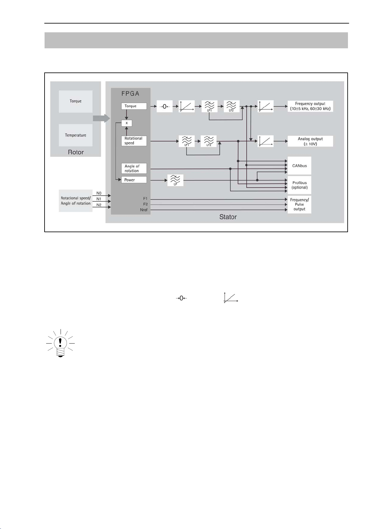
4 Signal flow
Low pass LP1: 0.05 Hz ... 4000 Hz
Low pass LP2: 0.05 Hz ... 100 Hz
Low pass LP: 0.1 Hz ... 80 Hz
11
Fig. 4.1: Signal flow diagram
The torque and the temperature signal are already digitized in the rotor and
transmission is therefore noise‐free.
The torque signal can be zeroed
, scaled (2‐point scaling) and
filtered via two low passes (LP1 and LP2). A further scaling of the frequency
output and the analog output is then possible.
NOTE
Scaling at position
(see Fig. 4.1) changes the internal calibration of
the torque transducer.
The speed signal can be filtered and also scaled for the analog output.
The angle of rotation signal, the performance signal (low pass filter LP) and
the temperature signal are only available on the fieldbusses.
The torque signal and the speed signal can be filtered via two low passes
connected in series, with the filter outputs also being available separately.
The scaled, unfiltered torque signal is used to calculate power. The resultant,
highly‐dynamically calculated power signal is filtered via a further low pass.
A1979-7.1 en HBM
Page 12

12
T12
For settings over 100 Hz (torque low‐pass filter 1 only), phase delay
compensation is run for the angle of rotation signal. This ensures that torque
and angle of rotation values that are measured simultaneously are also output
simultaneously.
For rotational speed and angle of rotation, two pulse series with a shift of 90°
are available as RS‐422 compatible signals.
A1979-7.1 enHBM
Page 13
T12
13
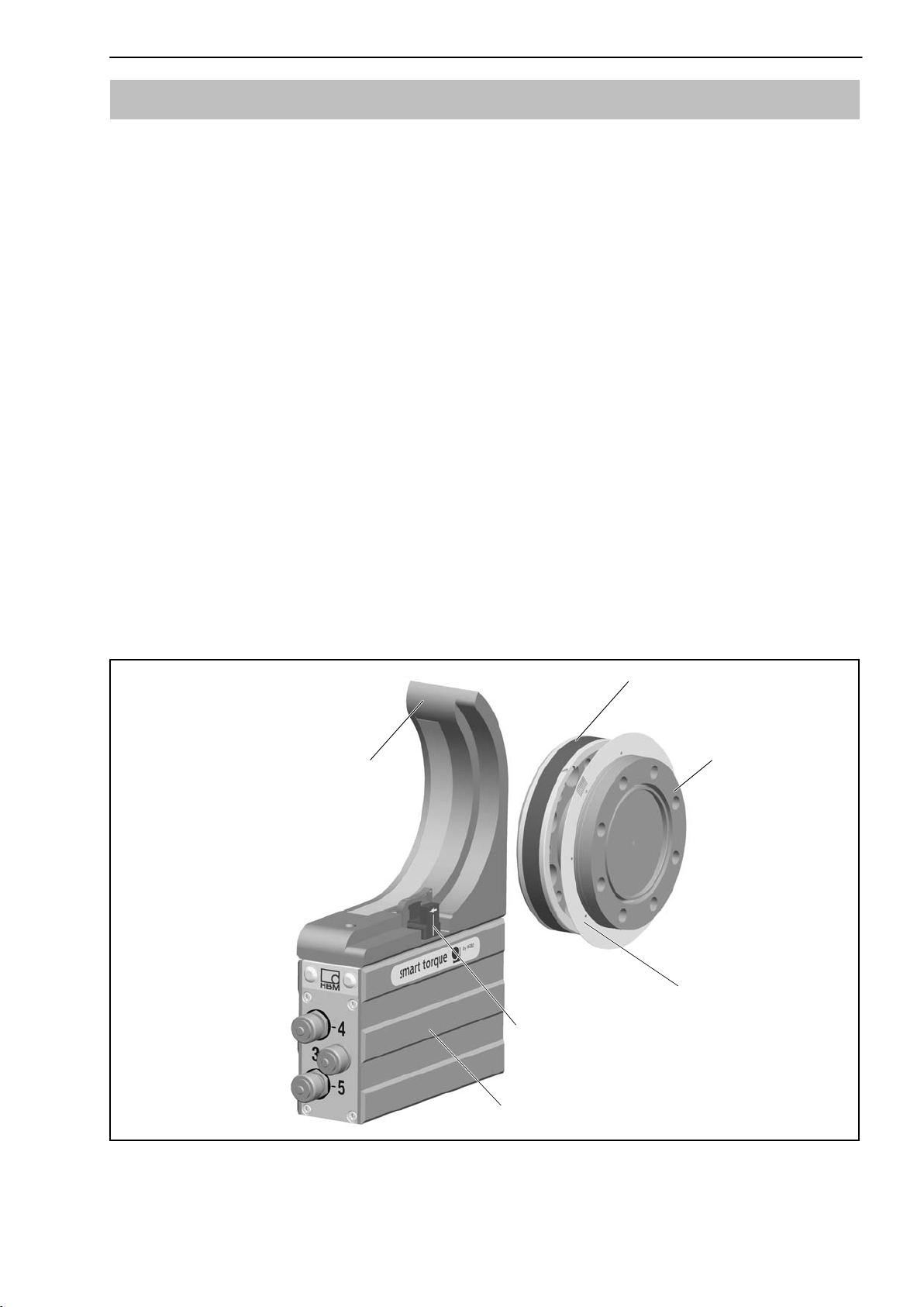
5 Structure and mode of operation
The torque transducer comprises two separate parts: the rotor and the stator.
Strain gages (SGs) for torque measurement have been installed on the rotor.
Carrier frequency technology (19.2 kHz carrier frequency) is used for
analyzing the SG and temperature signal. The rotor temperature is measured
at two measuring points and averaged.
The electronics for transmitting the bridge excitation voltage and the
measurement signal is located centrally in the rotor. The coils for the
noncontact transmission of excitation voltage and measurement signal are
located on the rotor's outer circumference of side A. The signals are sent and
received by a transmitter head. The transmitter head is mounted on the stator,
which houses the electronics for voltage adaptation and signal conditioning.
Connectors for inputs and outputs (for the connector pin assignment, see
chapter 8.3) are located on the stator. The transmitter head encloses the rotor
over a segment of about 120° and should be mounted concentrically around
the rotor (see chapter 6).
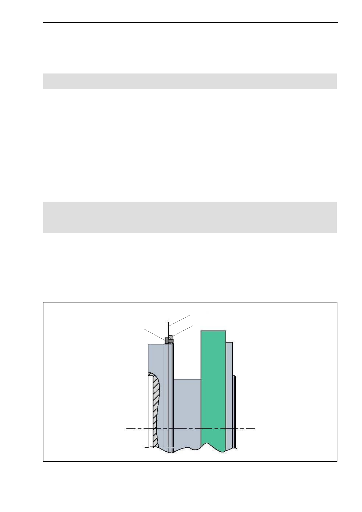
In the case of the speed measuring system option, the speed sensor is
mounted on the stator, the customer attaches the associated slotted disc on
the rotor. The optical speed measurement works on the infrared transmitted
light principle.
Side A
Transmitter head
Stator
Side B
Rotor
Slotted disc (option)
Speed sensor (option)
Housing
Fig. 5.1: Mechanical structure, exploded view
A1979-7.1 en HBM
Page 14

14
T12
6 Mechanical installation
WARNING
Handle the torque transducer carefully. The transducer might suffer
permanent damage from mechanical shock (e.g. dropping), chemical
effects (e.g. acids, solvents) or thermal effects (e.g. hot air, steam).
With alternating loads, you should glue the rotor connection screws into
the counter thread with a screw locking device (medium strength) to
exclude prestressing loss due to screw slackening.
The T12 torque transducer can be mounted directly with a relevant shaft
flange. It is also possible to directly mount a joint shaft or relevant compensat
ing element on opposite flange (using an intermediate flange when required).
Under no circumstances must the permissible limits specified for bending
moments, transverse and longitudinal forces be exceeded. Due to the torque
transducer's high torsional stiffness, dynamic changes on the shaft run are
minimized.
CAUTION
Check the effect on speeds and natural torsional oscillations critical to
bending, to prevent the transducer being overloaded by increases in
resonance.
6.1 Conditions on site
The T12 torque transducer is protected to IP54 according to EN 60529.
Protect the transducer from coarse dirt, dust, oil, solvents and moisture.
During operation, the prevailing safety regulations for the security of
personnel must be observed (see "Safety instructions").
There is wide ranging compensation for the effects of temperature on the
output‐ and zero signals of the T12 torque transducer (see specifications on
page 51). This compensation is carried out at static temperatures. This
guarantees that the circumstances can be reproduced and the properties of
the transducer can be reconstructed at any time.
If there are no static temperature ratios, for example, because of the temper
ature differences between flange A and flange B, the values given in the spe
cifications can be exceeded. Then for accurate measurements, you must
A1979-7.1 enHBM
Page 15
T12
15
ensure static temperature ratios by cooling or heating, depending on the
application. As an alternative, check thermal decoupling, by means of heat
radiating elements such as multiple disc couplings.
6.2 Mounting position
The transducer can be mounted in any position. With clockwise torque, the
output frequency is 10...15 kHz (Option 4, Code DF1/DU2: 60 kHz ... 90 kHz).
In conjunction with HBM amplifiers or when using the voltage output, a
positive output signal (0 V to +10 V) is present.
With counterclockwise torque, the output frequency is 5 kHz...10 kHz (Option
4, Code DF1/DU2: 30 kHz ... 60 kHz).
In the case of the speed measuring system, an arrow is attached to the head
of the sensor to clearly define the direction of rotation. When the transducer
rotates in the direction of the arrow, a positive speed signal is output.
6.3 Installing the slotted disc (speed measuring system
only)
To prevent damage to the speed measuring system's slotted disc during
transportation, it is not mounted on the rotor. Before installing the rotor in the
shaft run, the customer must attach it to the mounting ring. The mounting ring
and the associated speed sensor are already fitted at the factory.
The requisite screws, a suitable screwdriver and the screw locking device are
included in the list of components supplied.
Slotted disc
Fastening screw
Mounting ring
Fig. 6.1: Installing the slotted disc
A1979-7.1 en HBM
Page 16

16
CAUTION
When carrying out installation work, be careful not to damage the
slotted disc!
Installation sequence
1. Push the slotted disc onto the mounting ring and align the screw holes.
2. Apply some of the screw locking device to the screw thread and tighten
the screws (tightening torque < 0.15 N⋅m).
6.4 Installing the rotor
T12
NOTE
In general, the rotor identification plate is no longer visible after
installation. This is why we include with the rotor additional stickers
with the important ratings, which you can attach to the stator or any
other relevant test‐bench components. You can then refer to them
whenever there is anything you wish to know, such as the shunt signal.
Data can also be accessed through T12 Assistent.
To explicitly assign the data, the identification number and the
measuring range are specified on the rotor where they can be seen from
outside.
A1979-7.1 enHBM
Page 17
T12
17
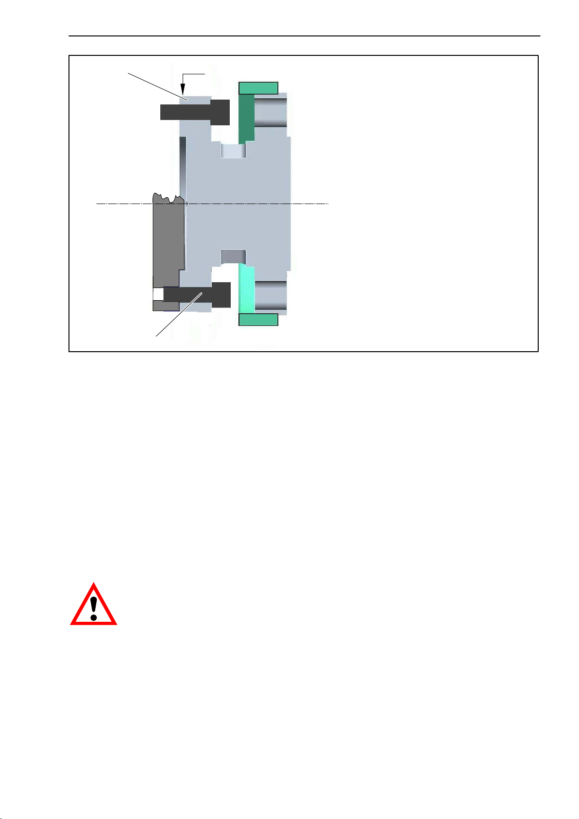
Fig. 6.2: Screw connections, flange B
1. Prior to installation, clean the plane surfaces of the transducer flange and
the counter flange. For safe torque transfer, the surfaces must be clean
and free from grease. Use a piece of cloth or paper soaked in solvent.
When cleaning, make sure that you do not damage the transmitter coils.
2. For the flange A screw connections, use hexagon‐socket screws DIN EN
ISO 4762 of property class 10.9 (measuring range 3 kN@m ... 10 kN@m:
12.9) of the appropriate length (depending on the connection geometry,
see Table 6.1).
We recommend fillister‐head screws DIN EN ISO 4762 or similar,
blackened, smoothheaded, permitted size and shape variance in
accordance with DIN ISO 4759, Part 1, product class A.
WARNING
With alternating load: Use a screw locking device (e.g. LOCTITE no. 242)
to glue the screws into the counter thread to exclude prestressing loss
due to screw slackening.
3. First tighten all the screws crosswise with 80% of the prescribed tightening
torque (Table 6.1), then tighten again crosswise, with the full tightening
torque.
A1979-7.1 en HBM
Page 18
18
4. There are relevant tapped holes on flange A for continuing the shaft run
mounting. Again use screws of property class 10.9 (measuring range of
3 kN@m ... 10 kN@m: 12.9) and tighten them with the prescribed torque, as
specified in Table 6.1.
Flange A
Fastening screw Z
T12
Fastening screw Z
Fig. 6.3: Screw connections, flange A
NOTE
Even if mounted correctly, the zero point adjusted at the factory may be
offset by up to 3 %. If this value has been exceeded, we recommend to
check the mounting conditions. If the remaining zero point offset is
greater than 1 % after dismounting, please send your transducer to our
factory in Darmstadt for evaluation.
CAUTION
With alternating loads, use a screw locking device to glue the
connecting screws into place. Guard against contamination from
varnish fragments.
A1979-7.1 enHBM
Page 19

T12
19
Measuring range
(NVm)
100 / 200 M8
500 M10 67
1 k M10 67
2 k M12 115
3 k M12
5 k M14 220
10 k M16 340
Fastening screws
(Z)
1)
Fastening screws
Property class
10.9
12.9
Prescribed
tightening torque
(NVm)
34
135
Table 6.1: Fastening screws
1)
DIN EN ISO 4762; black/oiled/m
= 0.125
tot
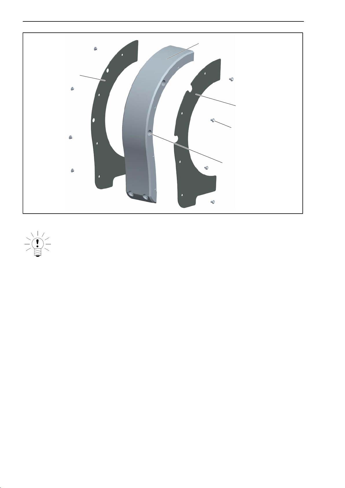
6.5 Fitting the protection against contact (option)
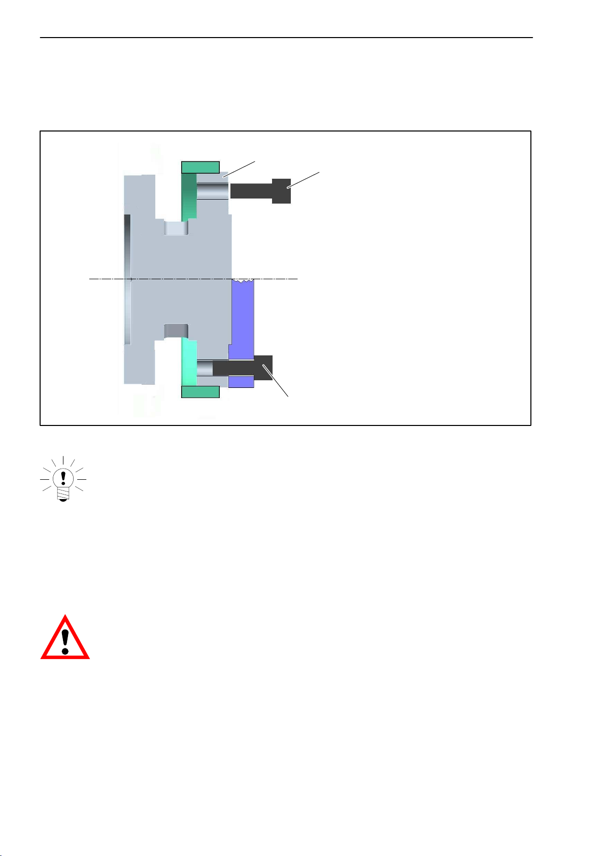
The protection against contact comprises two side parts and four covers. It is
screwed onto the stator housing.
CAUTION
Use threadlocker (e.g. LOCTITE 242) for locking all connecting screws.
1. Remove the side cover plates on the stator housing (see Fig. 6.4.)
A1979-7.1 en HBM
Page 20
20
T12
Cover plate
Cover plate
Fig. 6.4: Cover plates on the stator housing
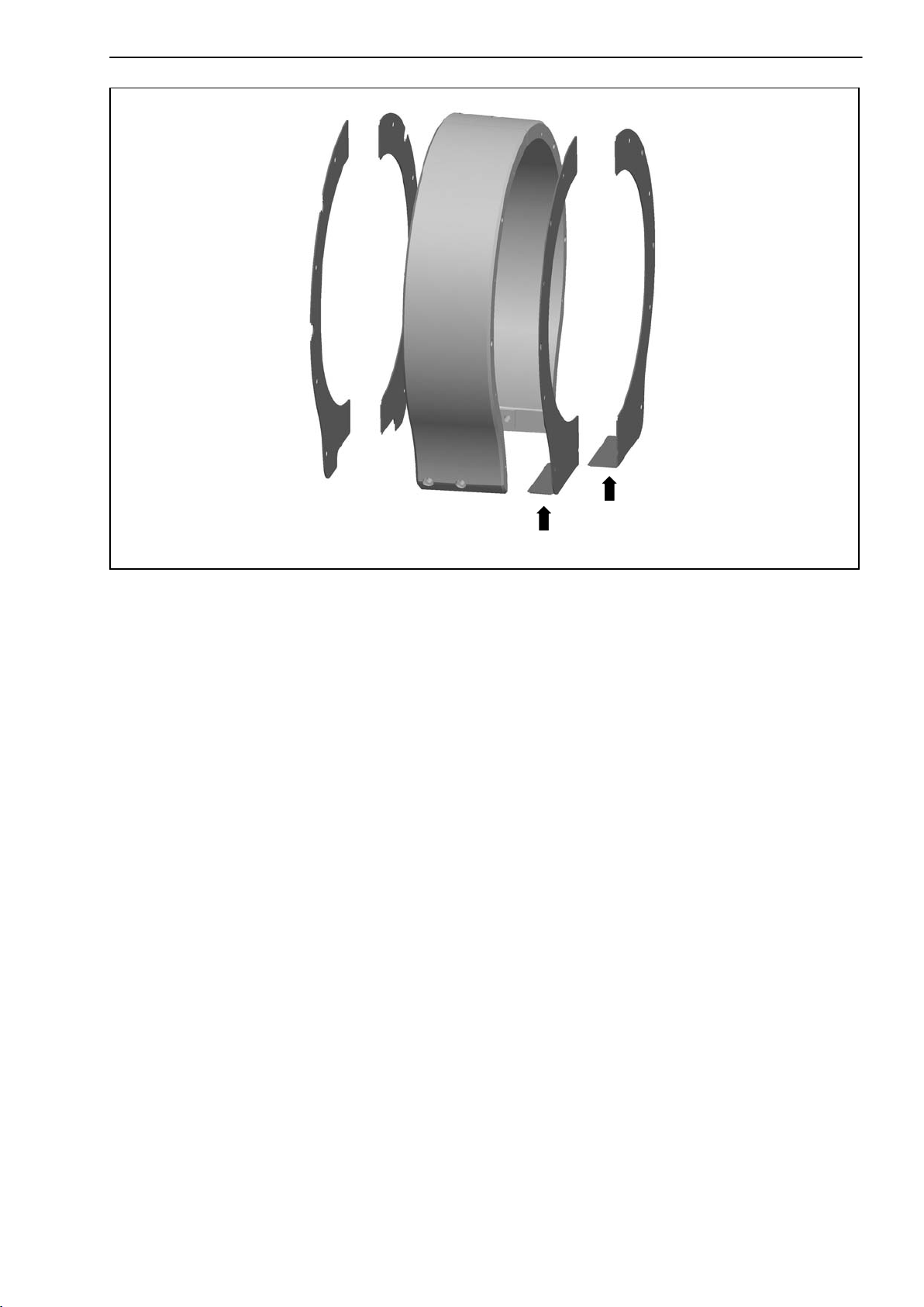
2. For 500 N@m - 3 kN@m measuring ranges and retrospective protec
tion against contact orders only: The tapped holes for the stop screws
are partly covered by the attached film. Make a semicircular cutout in the
film here, at least 6 mm in radius (e.g. with a cutter, see Fig. 6.5).
Now remove the threaded pins from the tapped holes on both sides of the
stator.
Threaded pin
Fig. 6.5: Cut out the film
A1979-7.1 enHBM
Page 21

T12
21
3. For 5 kN@m and 10 kN@m measuring ranges only: remove the threaded
pins from the tapped holes on both sides of the stator. Screw the spacing
bolt into the tapped hole on the side of the speed sensor (see Fig. 6.6).
Threaded pin
Spacing bolt
1
2
Fig. 6.6: Fitting the spacing bolt (for 5 kN@m and 10 kN@m only)
4. Screw the covers onto the side parts (use hexagon socket, 2 AF; tigh
tening torque M
= 1 N@m). It is essential to fit the cover with the cutouts
A
onto the side with the countersinks (see Fig. 6.7).
A1979-7.1 en HBM
Page 22
22
Cover with holes
T12
Side part
Cover with cutouts
2 AF
Countersink
Fig. 6.7: Fit the covers
NOTE
With the 5 kN@m and 10 kN@m measuring ranges, the cover plates of the
speed sensor side are angled at the bottom and must be fitted as shown
in Fig. 6.8.
A1979-7.1 enHBM
Page 23
T12
23
Fig. 6.8: Angled cover plates (for 5 kN@m and 10 kN@m measuring ranges)
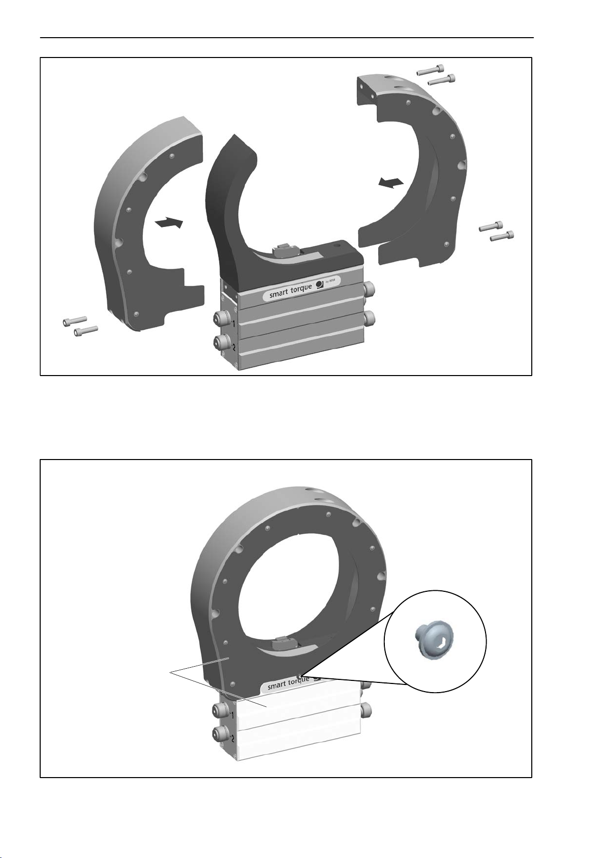
5. Fasten the preassembled side parts on the stator housing, each with two
M6 x 25 hexagon‐socket screws (5 AF). Tighten the screws hand‐tight.
6. Apply some of the screw locking device to the screw threads and screw
the side parts together, hand‐tight (2 M6 x 30 hexagon‐socket screws;
5 AF).
A1979-7.1 en HBM
Page 24
24
T12
M6 x 30
M6 x 25
M6 x 25
Fig. 6.9: Fit the halves of the protection against contact
7. Align the protection against contact in such a way that its end face is par
allel to the stator housing.
Stop screw (on
both sides)
Parallel surfaces
Fig. 6.10: Check for parallelism
A1979-7.1 enHBM
Page 25

T12
25
8. Now tighten all the screws with a tightening torque M
of 14 N@m.
A
9. Screw in the stop screws of the covers with a tightening torque of 2 N@m.
6.6 Installing the stator
On delivery, the stator has already been installed and is ready for operation.
There are four tapped holes on the base of the stator housing for mounting
the stator. Externally, two with a metric M6 thread, internally, two with a UNF
1/4" thread (closed with a plastic threaded pin).
For installation with metric thread, we recommend using two
DIN EN ISO 4762
10.9 of the appropriate length (depending on the connection geometry; not
included among the components supplied; tightening torque = 14 N@m).
NOTE
fillister‐head screws with hexagon sockets of property class
Provide a possibility for adjustment (e.g. slotted holes) for aligning
stator and rotor.
The stator can be mounted radially in any position (for example, "upside
down" installation is possible). You can also install the stator over the
protection against contact (option), see chapter 6.6.3.
maximum screw-in depth 10
maximum screw-in depth
+1
Fig. 6.11: Mounting holes in the stator housing (viewed from below)
With 5 kN⋅m and 10 kN⋅m torque transducers, we recommend supporting the
stator at the protection against contact in addition. Fig. 6.10 shows an exam
ple of how to fix an angle bracket using a bolt (A) or a threaded rod (B).
Please note that in this case the cover plates cannot be installed.
A1979-7.1 en HBM
Page 26

26
T12
A
B
∅6,6
∅11
Section through the countersink in the protection
against contact
Fig. 6.12: Supporting the stator with an angle bracket (5 kN⋅m and 10 kN⋅m)
6.6.1 Preparing with the mounting kit (included among the items sup
plied)
The supplied mounting kit contains self‐adhesive spacers, to make it easier
for you to align the stator to the rotor.
Use the spacers to align the rotor and the stator radially and axially.
Remove the
protective film
Fig. 6.13: Mounting kit spacer
A1979-7.1 enHBM
Page 27

T12
27
Radial alignment with spacers
The spacers should preferably be attached to the transmitter head, offset by
90°, as shown in Fig. 6.14. If your stator is equipped with a speed measuring
system, you must either shorten the spacers to an appropriate length or bond
them on a slightly staggered manner next to the speed measuring system.
90°
Spacers
Fig. 6.14: Radial position of the spacers
A1979-7.1 en HBM
Page 28

28
T12
Axial alignment with spacers
The red line on the spacers is used for axial alignment. Align the spacer in
such a way that the outer edge of the transmitter head is in line with the red
line (see Fig. 6.15).
Outer edge of
transmitter head
Red line
Fig. 6.15: Axial position of the spacers
Now remove the protective film and attach the spacer to the transmitter head,
as described.
CAUTION
Remove the spacers after installation.
6.6.2 Aligning the stator
1. Position the stator on an appropriate base plate in the shaft run, so that
there are sufficient opportunities for horizontal and vertical adjustments to
be made.
2. Should there be any misalignment in height, compensate for this by
inserting adjusting washers.
3. Initially, the fastening screws should only be hand‐tight.
4. Use the spacers to radially align the stator to the rotor.
A1979-7.1 enHBM
Page 29

T12
29
5. Use the spacers to axially align the stator to the rotor. The rotor should be
in line with the edge of the red spacer, see Fig. 6.16.
Transmitter rotor
Alignment line
Spacer
Fig. 6.16: Axial alignment to the rotor
6. Connect the power line (connector 1 or connector 3). Notice the LED to
the right of connector 4. The stator is correctly aligned, when the LED
successively
• flashes red for about 10 seconds
• flashes yellow for about 10 seconds
• then stays permanently green (CAN bus) or yellow or green
(PROFIBUS).
NOTE
When data are being exchanged via the CAN bus or the PROFIBUS, the
LED flashes green.
You can also use the T12 Assistant to check for the correct alignment. The
LED must stay green in the "Rotor clearance setting mode".
7. Now fully tighten the fastening screws (tightening torque: 14 N@m).
8. Remove the spacers, by first removing the adhesive strip and then the red
plastic strip.
A1979-7.1 en HBM
Page 30

30
9. Make sure that the air gap between the rotor and stator is free from
electrically conductive and other foreign matter.
6.6.3 Stator installation over the protection against contact (option)
You can also axially flange the stator over the protection against contact
(material: aluminum). Holes are provided in the side parts of the protection
against contact for this purpose. For this mounting, we recommend
fillister‐head screws M6 with hexagon sockets in accordance with
DIN EN ISO 4762; black/oiled/m
=0.125, of the appropriate length.
tot
T12
Fig. 6.17: Mounting holes in the protection against contact
A1979-7.1 enHBM
Page 31

T12
b
2
b
8
Customer adaptation
∅6.6
∅11
Measuring range Dimensions in mm
31
100 N⋅m ... 3 kN⋅m 56 43
5 kN⋅m 78 65
10 kN⋅m 86 73
Table 6.2: Mounting hole dimensions
b
2
b
8
Fig. 6.18: Face‐mounting on the engine shielding
6.7 Optical speed/angle of rotation measuring system
(option)
As the stator with the optical speed sensor only partially encloses the slotted
disc, if there is sufficient space available for installation, you can subsequently
move the stator tangentially over the ready‐mounted rotor.
For perfect measuring mode, the slotted disc of the speed measuring system
must rotate at a defined position in the sensor pickup.
A1979-7.1 en HBM
Page 32

32
T12
Axial alignment
There is a mark (orientation line) in the sensor pickup for axial alignment
(orientation line). When installed, the slotted disc should be exactly above this
orientation line. Divergence of up to "2 mm is permissible in measuring
mode (total of static and dynamic shift).
Slotted disc
Flange B
Orientation lines
Sensor pickup
Fig. 6.19: Position of the slotted disc in the speed sensor
Radial alignment
The rotor axis and the optical axis of the speed sensor must be along a line at
right angles to the stator platform. A conical machined angle (or a colored
mark) in the center of flange A and a vertical marker line on the sensor pickup
serve as aids to orientation.
A1979-7.1 enHBM
Page 33

T12
Centering point for aligning
the rotor
33
Marking
Fig. 6.20: Alignment marks on rotor and stator
Connect the power line (connector 1).
Switch the LED display mode of the T12 Assistant to "optical speed system"
setting mode and turn the rotor. Notice the LED to the right of connector 4;
this must stay green if the setting is correct (also see chapter 7.3).
CAUTION
Angle of rotation measurement is not suitable for static and quasi‐static
applications!
A1979-7.1 en HBM
Page 34

34
T12
7 LED status display
The LED in the stator housing (next to male device connector 4) has three
display modes: Standard (measuring mode), rotor clearance setting mode and
optical speed system setting mode.
7.1 Measuring mode operation
LED color Significance
Flashing green (fast) SDO Transfer taking place
Flashing green CAN Device has Operational status
Green For PROFIBUS option only: Data Exchange taking place
Flashing yellow (slow) Rotor communication taking place
Yellow For PROFIBUS option only: Searching for the baud rate or parameteriz
ation or configuration taking place or no Data Exchange taking place
Flashing red Overflow for measured value (amplifier input, measured value Ovfl.),
frequency or analog output
Red Error situation
1)
When PROFIBUS option exists: Messages to the PROFIBUS take precedence over messages to the CAN
bus.
1)
1)
7.2 Rotor clearance setting mode operation
LED color Significance
Green Rotor‐Stator alignment is OK
Yellow Rotor‐Stator alignment is borderline
Red Rotor‐Stator alignment is not OK
7.3 Speed measuring system setting mode operation
LED color Significance
Green The position of the two sensors is OK, the signals (F1/F2) are 90° or
270° phase‐shifted and can be correctly evaluated
Yellow The phase relation of the two sensor signals is not optimum, there is a
variation of 10° to 30°
Red The phase relation of the two sensor signals is not correct, there is a
variation of more than 30°
For more information on setting mode, look in the T12 Assistant online Help.
A1979-7.1 enHBM
Page 35

T12
35
8 Electrical connection
8.1 General hints
Detailed instructions for connecting the T12 to the CAN bus or the PROFIBUS
can be found in the "T12‐CAN bus/PROFIBUS" Internet description (in pdf
format) on the T12 system CD.
To make the electrical connection between the torque transducer and the
measuring amplifier, we recommend using shielded, low‐capacitance
measurement cables from HBM.
With cable extensions, make sure that there is a proper connection with
minimum contact resistance and good insulation. All plug connections or
sleeve nuts must be properly tightened.
Do not route the measurement cables parallel to power lines and control
circuits. If this cannot be avoided (in cable pits, for example), maintain a
minimum distance of 50 cm and also draw the measurement cable into a steel
tube.
Avoid transformers, motors, contactors, thyristor controls and similar
stray‐field sources.
CAUTION
Transducer connection cables from HBM with attached connectors are
identified in accordance with their intended purpose (Md or n). When
cables are shortened, inserted into cable ducts or installed in control
cabinets, this identification can get lost or become concealed. If this is
the case, it is essential for the cables to be re‐labeled!
NOTE
Cables and connectors for connections 1, 2 and 3 are compatible with
the T10FS torque flange.
8.2 Shielding design
The cable shielding is connected in accordance with the Greenline concept.
This encloses the measurement system (without a rotor) in a Faraday cage. It
is important that the shield is laid flat on the housing ground at both ends of
the cable. Any electromagnetic interference active here does not affect the
A1979-7.1 en HBM
Page 36

36
T12
measurement signal. Signal transmission between transmitter head and rotor
is purely digital and special electronic coding methods are used to protect
from electromagnetic interference.
In the case of interference due to potential differences (compensating
currents), supply voltage zero and housing ground must be disconnected on
the amplifier and a potential equalization line established between the stator
2
housing and the amplifier housing (copper conductor, 10 mm
wire cross
section).
If potential differences arise between the rotor and the stator on the machine,
perhaps due to unchecked leakage, and this causes interference, it can usu
ally be overcome by connecting the rotor directly to ground, for instance by a
wire loop. The stator should be fully grounded in the same way.
8.3 Connector pin assignment
Assignment for connector 1:
Supply voltage and frequency output signal.
Binder 423
61
5
72
3
4
Top view
Con
nector
pin
1 Torque measurement signal (frequency
2 Supply voltage 0 V; bk 5
3 Supply voltage 18 V ... 30 V bu 6
4 Torque measurement signal (frequency out
5
6 Shunt signal activation 5 V...30 V and TEDS
7
Assignment Color
output; 5 V
put; 5 V
Measurement signal 0 V;
for torque
Shunt signal 0 V;
Shielding connected to enclosure ground
1)
)
1)
) rd 12
symmetrical
Sub‐D
code
wh 13
connector
gy 8
gn 14
gy 8
pin
1)
Complementary signals RS‐422; for cable lengths of 10 m and longer, we recommend to
use a termination resistor R=120 ohms between wires (wh) and (rd).
CAUTION
Torque transducers are only intended for operation with a DC supply
voltage (separated extra‐low voltage), see page 36.
A1979-7.1 enHBM
Page 37

T12
Assignment for connector 2: Speed measuring system
37
Binder 423
Connector
pin
Assignment Color
code
Sub‐D
connector
pin
1 Speed measurement signal (pulse string,
1)
5 V
; 0°)
2
7
6
1
8
3
4
5
2
3 Speed measurement signal (pulse string,
4 No function bk
5
No function
1)
5 V
; 90°phase shifted) gy
TEDS for rotational speed
rd 12
bu
vt
6 Speed measurement signal (pulse string,
1)
5 V
Top view
; 0°)
7
8
Speed measurement signal (pulse string,
1)
5 V
; 90°phase shifted)
Measurement signal 0 V;
wh 13
gn
2)
bk
Shielding connected to enclosure ground
1)
Complementary signals RS‐422; for cable lengths of 10 m and longer, we recommend to use
a termination resistor R=120 ohms between wires (rd) and (wh) as well as (gy) and (gn).
2)
Wire color brown (br) with Kab 163 and Kab 164
2
15
3
9
14
8
Assignment for connector 2: Speed measuring system with reference pulse
Binder 423
pin
1 Speed measurement signal (pulse string,
2
Connector
7
6
1
8
3
4
5
2
3 Speed measurement signal (pulse string,
4 Reference signal (1 pulse/rev., 5 V1)) bk 3
5
6 Speed measurement signal (pulse string,
7
Top view
1)
Complementary signals RS‐422; for cable lengths of 10 m and longer, we recommend to use
8
a termination resistor R=120 ohms between wires (rd) and (wh); (bu) and (bk); (gy) and (gn).
2)
Wire color brown (br) with Kab 163 and Kab 164
Assignment Color
code
rd 12
1)
5 V
; 0°)
Reference signal (1 pulse/rev., 5 V1))
1)
5 V
; 90°phase shifted)
2)
TEDS for speed
1)
5 V
; 0°)
bu 2
gy
vt 9
wh 13
Speed measurement signal (pulse string,
1)
5 V
; 90°phase shifted)
Measurement signal 0 V;
gn
bk
2)
Shielding connected to enclosure ground
Sub‐D
connector
pin
15
14
8
A1979-7.1 en HBM
Page 38

38
Assignment for connector 3:
Supply voltage and voltage output signal.
T12
Binder 423
61
72
5
3
4
Top view
Connector
pin
1
2
3 Supply voltage 18 V to 30 V DC
4
5 No function
6 Shunt signal activation 5 V...30 V and TEDS for torque
7
Assignment
Torque speed measurement signal (voltage output; 0 V )
or speed measurement signal (0V)
Supply voltage 0 V;
Torque speed measurement signal (voltage output; "10 V)
or speed measurement signal ("10 V)
Shunt signal 0 V;
Shielding connected to enclosure ground
CAUTION
Do not use cable KAB 149 to connect the voltage output signal at AP01i
to ML01B of the MGCplus system! This cable is only suitable for the
frequency output signal connection.
NOTE
The analog output is designed as a monitoring output. The power
transmission of the torque transducer can cause interference on the
connected cable of up to 40 mV at 13.56 MHz. This interference can be
suppressed by connecting a 100 nF capacitor in parallel, directly at the
connected measuring device.
A1979-7.1 enHBM
Page 39

T12
Assignment for connector 4:
CAN bus standard; A‐coded, black washer
39
Binder 713
(M12x1)
5
Top view
12
43
Connector
pin
1 Shielding -
2
3 CAN ground -
4 CAN HIGH‐dominant high wh
5
Assignment Color
No function
CAN LOW‐dominant low
Shielding connected to enclosure ground
Assignment for connector 5:
CAN bus, second device connector; A‐coded, black washer
Binder 713
(M12x1)
12
Connector
pin
1 Shielding -
Assignment Color
code
-
bu
code
5
Top view
2
3 CAN ground -
4 CAN HIGH‐dominant high wh
43
5
No function
CAN LOW‐dominant low
Shielding connected to enclosure ground
Assignment for connector 5:
PROFIBUS (Option); B‐coded, violet washer
Binder 715
(M12x1)
5
Top view
12
43
Connector
pin
1 5 V (typ. 50 mA)
2
3 PROFIBUS ground
4 PROFIBUS B
5
Assignment
PROFIBUS A
Schielding
Shielding connected to enclosure ground
-
bu
A1979-7.1 en HBM
Page 40

40
T12
8.4 Supply voltage
The transducer has to be operated with a separated extra‐low voltage
(18 ... 30 V DC supply voltage) which normally supplies one or several con
sumer loads in a test bench. If the transducer is to be operated in a DC
1)
voltage network
voltages.
8.4.1 Supply voltage for self‐contained operation
The notes in this section relate to the self‐contained operation of the T12
without HBM system solutions.
The supply voltage is electrically isolated from signal outputs and shunt signal
inputs.
Connect a separated extra‐low voltage of 18 V...30 V to pin 3 (+) and pin 2
) of connectors 1 or 3. We recommend that you use HBM cable
(
KAB 8/00-2/2/2 and the relevant female Binder connectors, that at nominal
(rated) voltage (24 V) can be up to 50 m long and in the nominal voltage
range, 20 m long (see Accessories, Page 77). If the permissible cable length
is exceeded, you can supply the voltage in parallel over two connection
cables (males connectors 1 and 3). This enables you to double the
permissible length. Alternatively an on‐site power pack should be installed.
, additional measures have to be taken for discharging over
If you feed the supply voltage through an unshielded cable, the cable must be
twisted (interference suppression). We also recommend that a ferrite element
should be located close to the connector on the cable, and the stator should
be grounded.
CAUTION
The instant you switch on, a current of up to 4 A may flow and this may
switch off power packs with electronic current limiters.
1)
Distribution system of major size (e. g. including several test benches) for electrical power which may also
supply consumer loads with high nominal (rated) currents.
A1979-7.1 enHBM
Page 41

T12
41
9 Shunt signal
The T12 torque transducer supplies an electrical shunt signal, at either 50 %
or 10 % of the nominal (rated) torque, as selected. Activate this function via
the T12 Assistant or the shunt signal activation on connector 1 or connector 3
(see chapter 8.3). The shunt signal selected last in the T12 Assistant will then
be activated.
NOTE
Due to the internal singal processing, activation of the shunt signal may
be delayed by about 5 seconds.
To obtain stable conditions, the shunt signal should only be activated once the
transducer has been warming up for 15 minutes.
To enable the values of the test report to be reproduced, the bonndary condi
tions of comparability (e. g. mounting conditions) have to be reproduced.
NOTE
When measuring the shunt signal, the transducer should not be loaded,
because the signal is applied in addition.
The shunt signal is automatically deactivated after about 5 minutes.
A1979-7.1 en HBM
Page 42

42
T12
10 Loading capacity
Nominal (rated) torque can be exceeded statically up to the limit torque. If the
nominal torque is exceeded, additional irregular loading is not permissible.
This includes longitudinal forces, lateral forces and bending moments. Limit
values can be found in the "Specifications" section, Page 51.
10.1 Measuring dynamic torque
The torque transducer is suitable for measuring static and dynamic torques.
The following applies to the measurement of dynamic torque:
• The T12 calibration run for static measurements is also valid for dynamic
torque measurements.
• The natural frequency f
the moments of inertia J
of the mechanical measuring system depends on
0
and J2 of the connected rotating masses and the
1
T12's torsional stiffness.
Use the equation below to approximately determine the natural frequency f
0
of
the mechanical measuring system:
f0+
1
· cT·
2p
Ǹ
ǒ
f
)
1
Ǔ
J
2
1
J
1
0
J
c
= natural frequency in Hz
J2= mass moment of inertia in kg⋅m
1,
= torsional stiffness in N⋅m/rad
T
2
• The maximum vibration bandwidth is 200 % (measuring ranges 3 kN@m ...
10 kN@m: 160 %) of the typical nominal (rated) torque for the T12 (see the
specifications, Page 51). The vibration bandwidth must fall within the load
range designated by the upper and lower maximum torques. The same
also applies to transient resonance points.
Upper maximum
torque 100 %
0
Lower maximum
torque 100 %
Fig. 10.1: Permissible dynamic loading
Vibration bandwidth
200 % M
(3 kNm ... 10 kN@m:
160 %)
nom
A1979-7.1 enHBM
Page 43

T12
43
11 TEDS
TEDS (Transducer Electronic Data Sheet) allows you to store the transducer
data (characteristic values) in a chip, that can be read out by a connected
measuring device.
There are two TEDS blocks in the T12 digital torque transducer:
• TEDS 1 (torque): A choice of voltage sensor or frequency sensor/pulse
sensor
• TEDS 2 (speed/angle of rotation): Frequency sensor/pulse sensor
The data are written automatically into the TEDS blocks by the T12 Assistant,
when the parameters are stored. The same menu is used to select whether
the device should be presented as a voltage sensor or as a frequency sensor
or as a frequency or pulse sensor.
the conversion factors for the various engineering units.
A template is also stored, which provides
The T12 is a transducer, that is to say, the T12 does not read the TEDS
blocks, it only writes them. (We therefore strongly advise against editing the
values with the HBM TEDS Editor, for example!)
To read out the data and thus the parameterization of an MGC amplifier (such
as the ML60B or ML01B with AP01i), the relevant connection board is
connected to the T12 via cable KAB149 (torque) or KAB163 (speed).
You must then run the "TEDS" command in the MGC amplifier.
The MGC amplifier reads the data from the T12 TEDS block and parameters
are assigned accordingly.
You can also read the TEDS block data with the TEDS Editor.
CAUTION
To ensure that the data of the TEDS blocks correspond to the properties
of the T12 torque transducer, you must not overwrite the information
from the MGC.
For more information on TEDS, look in the T12 Assistant online Help.
A1979-7.1 en HBM
Page 44

44
T12
11.1 Content of the TEDS memory as defined in IEEE 1451.4
The information in the TEDS memory is organized into areas, which
are prestructured to store defined groups of data in table form.
Only the entered values are stored in the TEDS memory itself. The amplifier
firmware assigns the interpretation of the respective numerical values. This
places a very low demand on the TEDS memory. The memory content is
divided into three areas:
Area 1:
An internationally unique TEDS identification number (cannot be changed).
Area 2:
The base area (basic TEDS), to the configuration defined in standard
IEEE1451.4. The transducer type, the manufacturer and the transducer serial
number are contained here.
Example:
TEDS content for the T12/1 kN@m transducer
TEDS
Manufacturer HBM (31)
Model
Version letter
Version number 2 first point of stator ident. no.
Serial number 7 first point of stator ident. no.
T12 (15)
A
Area 3:
Data specified by the manufacturer and the user are contained in this area.
The “Value" column of the following table gives example values for a
T12/1kN⋅m torque transducer from HBM.
Torque
For the measured quantity torque, HBM has already described the template
“Frequency/Pulse Sensor" and the template “High Voltage Output Sensor".
A1979-7.1 enHBM
Page 45

T12
Template: Frequency/Pulse Sensor
Parameter Value Unit Requi
red
user
rights
Transducer Electrical
Signal Type
Minimum Torque 0.000 N@m CAL
Maximum Torque 1000 N@m CAL
Pulse Measurement Type Frequency
Pulse
Sensor
ID
45
Explanation
The physical measured quant
ity and unit are defined when
the template is created, after
which they cannot be changed.
Minimum Electrical
Value
Maximum Electrical Value 15000 Hz CAL
Mapping Method Linear
Discrete Signal Type Bipolar ID
Discrete Signal Amplitude 4 V
Discrete Signal Configu
ration
Transducer Response
Time
Excitation Level nom 24 V
Excitation Level min 18 V
Excitation Level max 30 V
Excitation Type DC
Excitation Current draw 0,5 A
Calibration Date 1-Nov-2006 CAL Date of the last calibration or
Calibration Initials HBM or PTB CAL Initials of the calibrator or calib
Calibration Period
(Days)
Measurement location ID 0 USR Identification number for the
10000 Hz CAL
Single
0 secon
ds
0 days CAL Time before recalibration, cal
The difference between these
values is the nominal (rated)
sensitivity.
creation of the test certificate (if
no calibration carried out), or of
the storage of the TEDS data (if
only nominal (rated) values
from the data sheet were
used).Format: day-monthyear.Abbreviations for the
months: Jan, Feb, Mar, Apr,
May, Jun, Jul, Aug, Sep, Oct,
Nov, Dec.
ration laboratory concerned.
culated from the date specified
under Calibration Date.
measuring point.Can be
assigned according to the
application. Possible values: a
number from 0 to 2047.
A1979-7.1 en HBM
Page 46

46
Template: High Level Voltage Sensor
Parameter Value Unit Requi
red
user
rights
Minimum Torque 0,000 N@m CAL
Maximum Torque 1000 N@m CAL
T12
Explanation
The physical measured quant
ity and unit are defined when
the template is created, after
which they cannot be changed.
Minimum Electrical Value 0 V CAL
Maximum Electrical Value 10 V CAL
Discrete Signal Type Bipolar ID
Discrete Signal Amplitude 5 V
Discrete Signal Single
Transducer Response
Time
Excitation Level nom 24 V
Excitation Level min 18 V
Excitation Level max 30 V
Excitation Type DC
Excitation Current draw 0,5 A
Calibration Date 1-Nov-2006 CAL Date of the last calibration or
Calibration Initials HBM or PTB CAL Initials of the calibrator or calib
Calibration Period (Days) 0 days CAL Time before recalibration, cal
Measurement Location ID 0 USR Identification number for the
0
The difference between these
values is the nominal (rated)
sensitivity.
creation of the test certificate (if
no calibration carried out), or of
the storage of the TEDS data (if
only nominal (rated) values
from the data sheet were
used).Format: day-monthyear.Abbreviations for the
months: Jan, Feb, Mar, Apr,
May, Jun, Jul, Aug, Sep, Oct,
Nov, Dec.
ration laboratory concerned.
culated from the date specified
under Calibration Date.
measuring point.Can be
assigned according to the
application. Possible values: a
number from 0 to 2047.
A1979-7.1 enHBM
Page 47

T12
Speed measuring sytem/Angle of rotation
For the measured quantity rotational speed/angle of rotation, HBM has
already described the template “Frequency/Pulse Sensor".
Template: Frequency/Pulse Sensor
Parameter Value Unit Requi
red
user
rights
Transducer Electrical
Signal Type
Minimum Frequency 0,000 Hz CAL
Maximum Frequency 108,000k Hz CAL
Pulse Measurement Type Frequency
Minimum Electrical Value 0 Hz CAL
Maximum Electrical Value 108,000k Hz CAL
Mapping Method Linear
Discrete Signal Type Bipolar ID
Discrete Signal Amplitude 4 V
Discrete Signal Configu
ration
Transducer Response
Time
Excitation Level nom 24 V
Excitation Level min 18 V
Excitation Level max 30 V
Excitation Type DC
Excitation Current draw 0,5 A
Calibration Date 1-Nov-2006 CAL Date of the last calibration or
Calibration Initials HBM or PTB CAL Time before recalibration, cal
Calibration Period
(Days)
Pulse
Sensor
Double
phase plus
zero index
0 secon
ds
0 days CAL Time before recalibration, cal
ID
Explanation
The physical measured quant
ity and unit are defined when
the template is created, after
which they cannot be changed.
creation of the test certificate (if
no calibration carried out), or of
the storage of the TEDS data (if
only nominal (rated) values
from the data sheet were
used).Format: day-monthyear.Abbreviations for the
months: Jan, Feb, Mar, Apr,
May, Jun, Jul, Aug, Sep, Oct,
Nov, Dec.
culated from the date specified
under Calibration Date.
culated from the date specified
under Calibration Date.
47
A1979-7.1 en HBM
Page 48

48
Template: Frequency/Pulse Sensor
Parameter Value Unit Requi
red
user
rights
Measurement location ID 0 USR Identification number for the
Transducer Electrical
Signal Type
Minimum Frequency 0,000E+000 degreesCAL
Maximum Frequency 3,6E+002 degreesCAL
Pulse Measurement Type Count
Minimum Electrical Value 0,0 Imp CAL
Maximum Electrical Value 360 Imp CAL
Mapping Method Linear
Discrete Signal Type Bipolar ID
Discrete Signal Amplitude 4 V
Discrete Signal Configu
ration
Transducer Response
Time
Excitation Level nom 24 V
Excitation Level min 18 V
Excitation Level max 30 V
Excitation Type DC
Excitation Current draw 0,5 A
Calibration Date 1-Nov-2006 CAL Date of the last calibration or
Pulse
Sensor
Double
phase plus
zero index
0 secon
ds
ID
Explantion
measuring point.Can be
assigned according to the
application. Possible values: a
number from 0 to 2047.
The physical measured quant
ity and unit are defined when
the template is created, after
which they cannot be changed.
The difference between these
values is the nominal (rated)
sensitivity.
creation of the test certificate (if
no calibration carried out), or of
the storage of the TEDS data (if
only nominal (rated) values
from the data sheet were
used).Format: day-monthyear.Abbreviations for the
months: Jan, Feb, Mar, Apr,
May, Jun, Jul, Aug, Sep, Oct,
Nov, Dec.
T12
A1979-7.1 enHBM
Page 49

T12
Template: Frequency/Pulse Sensor
Parameter Value Unit Requi
red
user
rights
Calibration Initials HBM or PTB CAL Time before recalibration, cal
Calibration Period
(Days)
Measurement location ID 0 USR Identification number for the
0 days CAL Time before recalibration, cal
Explantion
culated from the date specified
under Calibration Date.
culated from the date specified
under Calibration Date.
measuring point.Can be
assigned according to the
application. Possible values: a
number from 0 to 2047.
49
A1979-7.1 en HBM
Page 50

50
T12
12 Maintenance
The T12 torque transducer without speed measuring system is mainten
ance‐free.
12.1 Cleaning the speed measuring system
During operation and depending on the ambient conditions, the slotted disc of
the rotor and the associated stator sensor optics can get dirty. This becomes
noticeable:
• In transducers with a reference pulse, when an increment error is displayed
in the "Speed signal" status in the T12 Assistant
• In transducers without a reference pulse, when there are cyclic intrusions
into the speed signal
Remedy:
1. Use compressed air (up to 6 bar) to clean the slotted disc.
2. Carefully clean the optical system of the sensor with a dry or
spirit‐impregnated cotton bud or cloth.
CAUTION
Do not use any other solvent for cleaning the sensor optic.
Fig.12.1: Cleaning points on the speed sensor
A1979-7.1 enHBM
Page 51

T12
13 Specifications
Type T12
Accuracy class 0.03
Torque measuring system
Nominal (rated) torque M
nom
for reference only kft‐lb 75 150 375 750 1,500 2,250 3,750 7,500
Nominal (rated) sensitivity (range
between torque = zero and M
nom
)
Frequency output 10 kHz/60 kHz
Voltage output
Sensitivity tolerance (deviation of
the actual output quantity at M
nom
from the nominal (rated) sensitivity)
Fieldbusses
Frequency output
Voltage output
Output signal at torque = zero
Frequency output 10 kHz/60 kHz
Voltage output
Nominal (rated) output signal
Frequency output
with positive nominal (rated)
torque 10 kHz/60 kHz
with negative nominal (rated)
torque 10 kHz/60 kHz
Voltage output with
positive nominal (rated) torque
negative nominal (rated) torque
Low‐pass filter LP1
Low‐pass filter LP2
Load resistance
Frequency output
Voltage output
Long‐term drift over 48 h
Voltage output
Measurement frequency range
Frequency output/Voltage output
Group delay time (Low pass LP1:
4 kHz)
Frequency output 10 kHz/60 kHz
Voltage output
Scale range
Frequency output/Voltage output
Resolution
Frequency output 10 kHz/60 kHz
Voltage output
Residual ripple
Voltage output
1)
RS‐422 complementary signals, observe terminating resistance.
2)
Factory settings TP1=1,000 Hz; TP2=1 Hz.
N⋅m 100 200 500
kN⋅m 1 2 3 5 10
kHz
V
%
%
%
kHz
V
kHz
kHz
V
V
Hz
Hz
kΩ
kΩ
mV
Hz
Hz
ms
ms
%
Hz
mV
mV
15/90 (5 V symmetric1))
5/30 (5 V symmetric
0.05 ... 4,000 (4
0.05 ... 100 (4
0 ... 4,000 (-1 dB)
0 ... 6,000 (-3 dB)
10 ... 1,000 (of M
5/30
10
"0.05
"0.05
"0.1
10/60
0
1)
)
+10
-10
th
order Bessel, -1 dB)
th
order Bessel, -1 dB)
≥ 2
≥ 10
"3
320/250
500
)
nom
0.03/0.25
0.33
3
51
2)
2)
A1979-7.1 en HBM
Page 52

52
T12
Nominal (rated) torque M
nom
kN⋅m 1 2 3 5 10
for reference only kft‐lb 75 150 375 750 1,500 2,250 3,750 7,500
Temperature influence per 10 K in
the nominal (rated) temp. range
on the output signal, related to the
actual value of signal span
N⋅m 100 200 500
Fieldbusses
Frequency output
Voltage output
%
%
%
"0.03
"0.03
"0.1
on the zero signal, related to the
nominal (rated) sensitivity
Fieldbusses
Frequency output
Voltage output
Maximum modulation range
Frequency output 10 kHz/60 kHz
Voltage output
3)
%
%
%
kHz
V
"0.02 ("0.01 optional)
"0.02 ("0.01 optional)
"0.1
4 ... 16/24 ... 96
-10.2 ... +10.2
Power supply
Nominal (rated) supply voltage
(separated extra low voltage)
V
(DC)
18 ... 30
Current consumption in meas.
mode
A < 1 (typ. 0.5)
Current consumption in start‐up
mode
A < 4
Nominal (rated) power
consumption
Maximum cable length
W
m
< 18
50
Linearity deviation including hys
teresis, related to the nominal
(rated) sensitivity
Fieldbusses
Frequency output 10 kHz/60 kHz
Voltage output
%
%
%
"0.02 ("0.01 optional)
"0.02 ("0.01 optional)
"0.05
Rel. standard deviation of the
repeatability, per DIN1319, related
to variation of the output signal
Fieldbusses/frequency output % "0.01
voltage output % "0.03
Shunt signal 50 % of M
or 10 % of M
nom
nom
Tolerance of shunt signal related
to M
nom
% "0.05
Nominal trigger voltage V 5
Limit trigger voltage V 36
Shunt signal on V min. >2.5
Shunt signal off V max. <0.7
Max. switch-on period min user‐defined
Update rate CAN bus kHz 4.8 (and binary division ratios (2-64))
3)
Output signal range with a repeatable relationship between torque and output signal.
A1979-7.1 enHBM
Page 53

T12
Low pass filter LP1, LP2, LP
Low‐pass filter frequency output
th
4
order Nominal
(rated)
value f
(Hz)
4,000 4,000 6,000 0.32 0.25
2,000 2,015 3,418 0.4 0.33
1,000 1,029 1,866 0.48 0.41
500 505 852 0.74 0.67
200 202 340 1.52 1.45
100 101 177 2.27 2.2
50 50 88 4.22 4.15
20 25 44 8.12 8.05
10 12.5 22 15.9 15.9
0.5 0.8 1.38 248 248
0.2 0.2 0.34 992 992
0.1 0.1 0.17 1,980 1,980
0.05 0.05 0.08 3,960 3,960
Low‐pass filter voltage output
th
4
order Nominal
(rated)
value f
(Hz)
4,000 4,000 6,000 0.25
2,000 2,015 3,418 0.3
1,000 1,029 1,866 0.41
500 505 852 0.67
200 202 340 1.45
100 101 177 2.2
50 50 88 4.15
20 25 44 8.05
10 12.5 22 15.9
0.5 0.8 1.38 248
0.2 0.2 0.34 992
0.1 0.1 0.17 1,980
0.05 0.05 0.08 3,960
f
g
(-1 dB)
c
(Hz)
f
g
(-3 dB)
(Hz)
Group delay
time
10 kHz"5 kHz
(ms)
Group delay
time
60 kHz"30 kHz
(ms)
5 6.25 11 31.5 31.5
2 3.1 5.5 62.3 62.3
1 1.6 2.75 124 124
f
g
(-1 dB)
c
(Hz)
f
g
(-3 dB)
(Hz)
Group delay time
(ms)
5 6.25 11 31.5
2 3.1 5.5 62.3
1 1.6 2.75 124
53
A1979-7.1 en HBM
Page 54

54
T12
Nominal (rated) torque
M
nom
N⋅m 100 200 500
kN⋅m 1 2 3 5 10
for reference only kft‐lb 75 150 375 750 1,500 2,250 3,750 7,500
Speed measuring system/measuring system for angle of rotation
Optical, by means of infrared light and metallic slotted
disc
Num
Mechanical increments
ber
360 720
Positional tolerance of the
increments
mm "0.05
Tolerance of the slot width mm "0.05
Pulses per rotation
(adjustable)
Num
ber
360; 180; 90; 60; 45; 30 720; 360;
180; 120;
90; 60
Pulse frequency at nominal
(rated) speed n
Option 3, Code L
Option 3, Code H
nom
4)
4)
kHz 90 72 120
kHz 108 96 168
Minimum speed for
sufficient pulse stability
rpm 2
Group delay time μs < 5 (typ. 2.2)
Hysteresis of reversing the
direction of rotation with
relative vibrations between
rotor and stator
Torsional vibrations
of the rotor
Degree
< approx. 2
Radial vibration amplitudes
of the stator
mm
< approx. 2
Permitted degree of soiling,
in the optical path of the sen
sor fork (lenses, slotted disc)
%
< 50
Swirl influence on the zero
point, through mounted in
crement disc, related to
nominal (rated) torque
Option 3, Code L
Option 3, Code H
4)
4)
Output signal
frequency/pulse output
%
%
V
<0.05
<0.08
<0.03
<0.04
<0.03
<0.03
<0.02
<0.02
55) symmetric; 2 square wave signals
approx. 90° phase shifted
<0.01
<0.01
Load resistance kΩ ≥ 2
4)
See page 76
5)
RS‐422 complementary signals, observe terminating resistances.
A1979-7.1 enHBM
Page 55

T12
55
Nominal (rated) torque M
for reference only kft‐lb 75 150 375 750 1,500 2,250 3,750 7,500
Rotational speed
Fieldbusses
Resolution rpm 0.1
System accuracy (at torsional
vibrations of max. 3 % with double
speed frequency)
Max. speed deviation at nominal
(rated) speed (100 Hz‐filter)
Voltage output
Measuring range V " 10
Resolution mV 0.33
Scale range % 10 ... 1,000
Overmodulation limits V " 10.2
Load resistance kΩ > 10
Linearity error % < 0.03
Temperature effect per 10 K in the
nominal (rated) temperature range
on the output signal, related to the
actual value of signal span
on the zero signal % < 0.03
Residual ripple mV < 3
Low‐pass filter (4
Cut‐off frequencies (-1 dB) LP1
Cut‐off frequencies (-1 dB) LP2
Update rate CAN bus kHz 4.8 (and binary division ratios (2-64))
th
nom
order)
N⋅m 100 200 500
kN⋅m 1 2 3 5 10
ppm 150
rpm 1.5
% < 0.03
HzHz1,000; 500; 200; 100; 50; 20; 10; 5; 2; 1; 0.5; 0.2;
0.1; 0.05
100; 50; 20; 10; 5; 2; 1; 0.5; 0.2; 0.1; 0.05
A1979-7.1 en HBM
Page 56

56
T12
Nominal (rated) torque M
nom
kN⋅m 1 2 3 5 10
for reference only kft‐lb 75 150 375 750 1,500 2,250 3,750 7,500
Angle of rotation
Accuracy De
N⋅m 100 200 500
gree
1 (typ. 0.1)
Resolution De
gree
0.01
Correction of the phase delay
deviation between torque LP1 and
angle of rotation for filter frequen
cies
Hz 4,000; 2,000; 1,000; 500; 200; 100
Measuring range De
gree
0 ... 360 (singleturn) up to "1,440 (multiturn)
Power
Measurement frequency range Hz 80 (-1 dB)
Resolution W 1
Full scale value W
P
max
+ M
nom
@ n
nom
@
p
30
[M
[n
nom
nom
] in N⋅m
] in rpm
Temperature effect per 10 K in the
nominal (rated) temperature range
on the power signal, related to the
full scale value
% "0.05@n/n
nom
Linearity deviation including hys
teresis, related to the full scale value
% "0.02@n/n
nom
Sensitivity tolerance (deviation of
the actual signal span of the power
signal related to the full scale value)
Low‐pass filter (1
st
order)
Cut-off frequencies
% "0.05
Hz
100; 10; 1; 0.1
Meas.
Measuring range CAN bus
val
600
ues /s
A1979-7.1 enHBM
Page 57

T12
Temperature signal rotor
Nominal (rated) torque M
nom
for reference only kft‐lb 75 150 375 750 1,500 2,250 3,750 7,500
Accuracy K 1
Measurement frequency range Hz 5 (-1 dB)
Resolution K 0.1
Physical unit - °C
Sampling rate Measured
Fieldbusses
CAN bus
Protocol - CAN 2.OB, CAL/CANopen compatible
Sampling rate Measured
Hardware bus link per ISO 11898
Baud rate kBit/s 1000 500 250 125 100
Maximum line length m 25 100 250 500 600
Connection
Profibus DP
Protocol - Profibus DP Slave, per DIN 19245‐3
Baudrate MBaud max. 12
Profibus ident no. - 096C (hex)
Input data, max. Byte 152
Output data, max. Byte 40
Diagnosis data Byte 18 (2@4 byte module diagnosis)
Connection - 5‐pole, M12x1, B‐coding, potential separated from
Update rate PROFIBUS
6)
Configuration entries
v 2 Measured
v 4
v 8
v 12
v 16
u 16 150
Limit value switch (on fieldbusses only)
Number - 4 for torque, 4 for rotational speed
Reference level -
Hysteresis % 0 ... 100
Setting accuracy Digit 1
Response time
(LP1= 4,000 Hz)
TEDS (Transducer Electronic Data Sheet)
Number - 2
TEDS 1 (torque) - Optional voltage sensor or frequency sensor
TEDS 2
(rotational speed/angle of rot.)
6)
With simultaneously activated CAN‐PDOs, the profibus update rate is reduced. With PDO output rate di
vider: v4 by factor 2; .v2 by factor 4; 1 by factor 8.
N⋅m 100 200 500
kN⋅m 1 2 3 5 10
values /s
values /s
max. 4,800 (PDO)
40
5‐pole, M12x1, A‐coding per CANopen DR‐303‐1
-
V1.3, potential separ. from supply and meas. mass
supply and measuring mass
4,800
values /s
2,400
1,200
600
300
Torque LP1 or LP2
Rotational speed LP1 or LP2
ms typ. 3
- Frequency‐/pulse sensor
57
A1979-7.1 en HBM
Page 58

58
General data
Nominal (rated) torque M
nom
for reference only kft‐lb 75 150 375 750 1,500 2,250 3,750 7,500
EMC
EME (Emission per EN61326-1,
table 3)
RFI voltage
RFI performance
RFI field strength
Immunity from interference
(EN61326‐1, table A.1)
Electromagnetic field (AM) V/m 10
Magnetic field A/m 30
ESD
Contact discharge kV 4
Air discharge kV 8
Burst kV 1
Surge kV 1
Line‐conducted disturbance
(AM)
Degree of protection per
EN60529
Weight, approx. Rotor kg 1.1 1.8 2.4 4.9 8.3 14.6
Stator kg 2.3 2.4 2.5 2.6
Reference temperature °C [°F] +23 [73.4]
Nominal (rated) temperature
range
Service temperature range °C [°F] -10 ... +60 [+14 ... +140]
Storage temperature range °C [°F] -20 ... +70 [−4 ... +158]
Impact resistance, test severity
level per DIN IEC 68; part 2‐27;
IEC 68‐2‐27‐1987
Number of impacts n 1,000
Duration ms 3
Acceleration (half-sine) m/s
Vibration resistance, test se
verity level per DIN IEC 68; part
2‐6; IEC68‐2‐6‐1982
Frequency range Hz 5 ... 65
Duration h 1.5
Acceleration (amplitude) m/s
Nominal (rated) speed n
Option 3, Code L
Option 3, Code H
7)
See page 76
7)
7)
nom
N⋅m 100 200 500
kN⋅m 1 2 3 5 10
-
-
-
Class A
Class A
Class A
V 3
- IP 54
°C [°F] +10 ... +60 [+50 ... +140]
2
2
650
50
rpm 15,000 12,000 10,000
rpm 18,000 16,000 14,000 12,000
T12
A1979-7.1 enHBM
Page 59

T12
59
Nominal (rated) torque M
nom
N⋅m 100 200 500
kN⋅m 1 2 3 5 10
for reference only kft‐lb 75 150 375 750 1,500 2,250 3,750 7,500
Load limits
8)
Limit torque, (static) "
related to M
nom
% 200 160
Breaking torque, (static) "
related to M
nom
Axial limit force (static) "
% > 400 > 320
kN 5 10 16 19 39 42 80 120
Axial limit force
(dynamic) amplitude
Lateral limit force (static) "
kN 2.5 5 8 9.5 19.5 21 40 60
kN 1 2 4 5 9 10 12 18
Lateral limit force
(dynamic) amplitude
kN 0.5 1 2 2.5 4.5 5 6 9
Bending limit moment
(static) "
N⋅m 50 100 200 220 560 600 800 1200
Bending limit moment
(dynamic) amplitude
N⋅m 25 50 100 110 280 300 400 600
Oscillation bandwidth per
DIN 50100 (peak‐to‐peak)
8)
Each type of irregular stress can only be permitted with its given limit values (bending moment, lateral or
axial load, exceeding the nominal (rated) torque) if none of the others can occur. Otherwise the limit values
must be reduced. If for instance 30 % of the bending limit moment and also 30 % of the lateral limit force
are present, only 40 % of the axial limit force are permitted, provided that the nominal (rated) torque is not
exceeded. With the permitted bending moments, axial, and lateral limit forces, measuring errors of about
0.3 % of the nominal (rated) torque can occur.
9)
The nominal (related) torque must not be exceeded.
9)
N⋅m
200 400 1,000 2,000 4,000 4,800 8,000 16,000
A1979-7.1 en HBM
Page 60

60
T12
Nominal (rated) torque
M
nom
N⋅m 100 200 500
kN⋅m 1 2 3 5 10
for reference only kft‐lb 75 150 375 750 1,500 2,250 3,750 7,500
Mechanical data
Torsional stiffness c
Torsion angle at M
Axial stiffness c
Radial stiffness c
nom
a
r
T
kN⋅m/
rad
230 270 540 900 2,300 2,600 4,600 7,900
Degree 0.048 0.043 0.055 0.066 0.049 0.066 0.06 0.07
kN/mm 420 800 740 760 950 1000 950 1,600
kN/mm 130 290 550 810 1,300 1,500 1,650 2,450
Stiffness with bending
moment about a radial
axis c
b
kN⋅m/
degree
3.8 7 11.5 12 21.7 22.4 43 74
Maximum excursion at
axial limit force
mm < 0.02 < 0.03 < 0.05 < 0.1
Additional max. radial
run‐out deviation at lat
eral limit force
mm
<0.02
Additional plane‐paral
lel deviation at bending
limit moment
(with j d
)
B
mm
<0.03 <0.05 <0.07
Balance quality‐level
per
DIN ISO 1940
Max. limits for relative
shaft vibration (peak‐to‐
10)
peak)
Undulations within the
range of the connecting
μm
Normal mode (continuous operation)
Start-Stop mode/resonance ranges (temporary)
G 2.5
(n in rpm)
s
s
(p*p)
(p*p)
+
+
9000
13200
flanges per ISO 7919-3
Mass moment of inertia
of the rotor
IV (around rotating axis) kg⋅m20.0023 0.0033 0.0059 0.0192 0.037 0.097
I
with optical speed
V
measuring system
kg⋅m20.0025 0.0035 0.0062 0.0196 0.038 0.0995
Proportionate mass mo
ment of inertia for
assembly side
without speed measu
ring system
% 58 56 54 53
with optical speed mea
suring system
% 56 54 53 52
Max. permissible static
eccentricity
of the rotor (radially) to
stator center
without speed measu
ring system
with speed measuring
system
mm
mm
" 2
" 1
Max. permissible axial
dis‐placement of the
rotor to stator
10)
The effects of radial deviation, eccentricity, defect of form, notches, marks, local residual magnetism,
structural inhomogeneity or material anomalies on vibration measurements need to be taken into account
and distinguished from the actual undulation.
mm
" 2
Ǹ
n
Ǹ
n
A1979-7.1 enHBM
Page 61

T12
14 Dimensions
14.1 Rotor dimensions
61
b
3
b
5
zi
c
z
∅d
x
S
(Center of the installation)
∅d
∅d
=Measuring plane
x
s
b
2
b
c
b
3
5
b
1
b
b
4
7
2
A
G
F
za
∅d
∅d
∅d
6
d
A
∅d
∅d
B
View A
(6x605 for
100 NVm ... 200 NVm)
8xY
Plane of temperature
measurement
Dimensions without tolerances per DIN ISO 2768‐mK
Measuring range
b
b
1
b
2
3
Dimensions in mm
b
b
4
b
5
b
6
∅d
c d x
7
B
S
Y
100 N⋅m/200 N⋅m 22 60 18 4 4 47.15 14 2 12.5 30 M8
500 N⋅m/1 kN⋅m 22 60 18 4 4 45.7 14 2 8 30 M10
2 kN⋅m/3 kN⋅m 23 64 20 5 4 47.7 14 2.5 8 32 M12
5 kN⋅m 24.8 84 26 3.3 3 62.7 17.5 2.8 8 42 M14
10 kN⋅m 24.8 92 30 3.3 4 66.7 17.5 3.5 10 46 M16
Measuring range
∅d
∅d
A
∅d
B
∅d
C
Dimensions in mm
∅d
F
G
∅d
C12
∅d
K
S
∅d
∅d
Z
za g5
∅d
100 N⋅m/200 N⋅m 115.5 84 99 101 11 0 14 8.2 131 57 57
500 N⋅m/1 kN⋅m 136.5 101.5 120 124 133 17 10 151 75 75
2 kN⋅m/3 kN⋅m 172.5 130 155 160 169 19 12 187 90 90
5 N⋅m 200.5 155.5 179 188 197 22 14.2 221 110 110
10 kN⋅m 242.5 196 221 230 239 26 17 269 140 140
H6
zi
A1979-7.1 en HBM
Page 62

62
14.2 Stator dimensions 100 N⋅m ... 200 N⋅m with speed
measuring system (in mm)
View Z
Reserved additional space for connec
Reserved additional space for mounting
and dismounting approx. j 20
Female cable connector in 4 an
gular positions adjustable
min.43
ted status min. 10
approx. V20
Side view Y
602
(28)
32
18
22
3
4
14
2
(18)
24
4
*)
approx. 54
Accessories female cable connector 7‐
alternatively 8‐pin 90° cable run
M6
Maximum thread reach 10
180
150
+1
UNF 1/4″.
Maximum thread reach 0.4″
114.3 = 4 1/2″
89.5
+0.02
″
approx. 100
Reserved additional space for
connection cable with male
connector
Side view X
T12
∅115.5
g5
∅101
∅110
∅57
66
24
8
10
(28)
28
56
2
H6
∅57
45
4
A
∅99
X
∅131
260
∅84
Y
194.5
62
28
6.5
Z
Top view
A1979-7.1 enHBM
Page 63

T12
14.3 Stator dimensions 100 N⋅m ... 200 N⋅m with speed
measuring system (in mm)
View A
Only with speed measu
ring and speed measu
ring system with refe
rence marker.
∅84
63
A1979-7.1 en HBM
Page 64

64
14.4 Stator dimensions 100 N⋅m ... 10 kN⋅m with speed
measuring system (in mm)
View Z
Reserved additional space for
connected status min. 10
Reserved additional space for moun
ting and dismounting approx. j 20
min. 43
*)
M6
Maximum thread reach 10
180
150
Reserved additional
space for connection
cable with male connector
+1
approx. 100
T12
Female cable connector in 4
angular positions adjustable
Accessories female cable connector
7‐ alternatively 8‐pin 90° cable run
Side view Y
X
approx. 54
H1
UNF 1/4”
Maximum thread reach 0.4”
114.3 = 4 1/2”
*)
Min. 14 mm with 5 kN⋅m and 10 kN⋅m
b
+0.02”
Air gap area:
Radial = 10 mm
Axial = b
(see page 61)
2
H2
Side view X
Y
66
24
8
10
28 (28)
45
Z
Top view
Stator center
Dimensions without tolerances per DIN ISO 2768‐mK
Only with speed measuring system and
speed measuring system with reference mark
Measuring range (NVm) Dimensions in mm
b ∅D H1 H2
100, 200 81 122 260 194.5
500, 1 k 91.5 143 280 204.5
2 k, 3 k 109.5 179 310 222.5
5 k 123.5 207 333 239.5
10 k 144.5 249 369 263.5
62
28
6.5
56
A1979-7.1 enHBM
Page 65

T12
65
14.5 Stator dimensions 100 NVm ... 200 NVm with protection
against contact (in mm)
(Protection against contact, complete)
58
1
56
(Protection
against contact)
(Cover plate)
1
(Cover plate)
B
89.3
(Stop screw)
∅118
23
(Protection against contact, complete)
A
(Protection against contact)
307
V
V
81
88
194.5
58
56
3212
102.5
93.5
0,55
[projection]
Speed sensor
V
Dimensions of opening (only with speed
and without opening with standard ver
sion (without speed measuring system)
measuring system)
View A
View without protection against
contact (half)
Included in standart version!
Parts on both sides need to be
removed for mounting the
protection against contact.
A1979-7.1 en HBM
Page 66

66
T12
14.6 Stator dimensions 100 NVm ... 200 NVm with protection
against contact (in mm)
View B
+2
225
205
196
185
-2
Z
∅11
Z
∅6.6
Z
Z
40
88
Connection apertures Z
(Protection against contact
View without protection against contact
56
(∅11)
43
(∅6.6)
Connection aperture with spot face
A1979-7.1 enHBM
Page 67

T12
14.7 Stator dimensions 500 NVm ... 1 kNVm with protection
against contact (in mm)
(58)
58 (Protection against contact, complete)
11
56
(Cover plate) (Cover plate)
(Protection
against contact)
A
∅ 139
11
(56)
12 32
67
99.3
Stop screw
+2
∅ 223
∅ 205
∅ 196
∅ 187
-2
Z
Z
∅ 11
Z
Z
View A
98
317
103.5 102.5
204.5
View without protection
against contact (half)
∅ 6.6
40
90
98
View without cover plate
(56) Protection against contact
∅ 11
43
∅ 6.6
Connection aperture with spot
face
A1979-7.1 en HBM
Page 68

68
14.8 Stator dimensions 2 kN⋅m ... 10 kN⋅m with protection
against contact (in mm)
b
b
(Cover plate)
b
Protection against contact, complete
1
3
b
b
2
3
(Cover plate)
H7
Stop screw
∅d
b
A
1
H3
H2
H1
4
b6b
1
b
7
b
2
5
H4 H5
T12
∅d
2
∅d
3
∅d
4
∅d
5
Z
Z
∅11
∅6.6
b
9
Z
Z
b
2
H6
b
(∅6.6)
8
View without protection
against contact (half)
View A
Protection against contact
(∅11)
Connection aperture with spot face
View without cover plate
Measuring range
b1b2b3b4b5b6b7b
Dimensions in mm
b9H
8
H
H
1
2
H
3
H
4
6
2 kN⋅m/3 kN⋅m 58 56 1 2 4 12 32 43 97.5 11 6 222.5 353 121.5 107 120.5 117.3
5 kN⋅m 80 78 1 2 2 12 32 65 99 133 239.5 384 138.5 120 134.5 134.3
10 kN⋅m 88 86 1 2 2 12 32 73 99 157 263.5 429 162.5 145 155.5 158.3
Measuring range Dimensions in mm
∅d
1
2 kN⋅m/3 kN⋅m 175 259
5 kN⋅m 203 289
10 kN⋅m 245 331
∅d
2
+2
+2
+2
∅d
3
241 232 223
269 260 249
311 302 291
∅d
4
H
H
5
7
∅d
5
-2
-2
-2
A1979-7.1 enHBM
Page 69

T12
14.8.1 Dimensions cover plates 100 N⋅m ... 200 kN⋅m
Screw head M3
1:4
Screw head M4
Outside
diameter=7
Height=2
Outside
diameter=9
Height=2.5
[Stop screw]
69
A1979-7.1 en HBM
Page 70

70
14.8.2 Dimensions cover plates 500 N⋅m ... 10 kN⋅m
Screw head
Outside
diameter=7
Height=2
Screw head
(Stop screw)
Outside diameter=9
Height=2.5
T12
Distance bolt only with
5 kN@m and 10 kN@m
14.9 Mounting dimensions
Center of rotor
Center of stator
c
ba
Reserved additional space for fieldbus connection
cable, approx. 140 mm from plug connection surface
Mounting dimensions
Measuring
Mounting dimension (mm)
range
a b c
100 N⋅m
200 N⋅m
4 0 2
500 N⋅m
1 kN⋅m
2 2 0
2 kN⋅m
3 kN⋅m
5 3 1
5 kN⋅m 25 3 11
10 kN⋅m 33 3 15
(Tolerance "1 mm)
A1979-7.1 enHBM
Page 71

T12
15 Additional technical information
15.1 Radial and axial run‐out tolerances
Axial run‐out AB
Radial run‐out AB
Hardness 46 ... 54 HRC
0.8
Quality of the axial and radial
run‐out surfaces (A, B and AB)
B
Internal centering
71
A
Measuring range (NVm) Axial run-out tolerance (mm) Radial run-out tolerance (mm)
100 0.01 0.01
200 0.01 0.01
500 0.01 0.01
1 k 0.01 0.01
2 k 0.02 0.02
3 k 0.02 0.02
5 k 0.025 0.025
10 k 0.025 0.025
A1979-7.1 en HBM
Page 72

72
T12
16 Delivery status
The parameter factory settings of are marked with an asterisk (*). Underlined parameters
will not be overwritten by reset to factory settings.
SYSTEM
General settings
Project name My Project
Language Deutsch; English
Specify passcode (1 – 9999) 0
Passcode activ? Yes*; No
Reactivate passcode Reactivate passcode
LED display mode Standard (measuring mode)
Mounting mode rotor distance
Mounting mode optical speed system
Fieldbus interface
CANopen
CAN adress 110
CAN baud rate 100 kB; 125 kB; 250 kB; 500 kB; 1000 kB*
LSS manufacturer number 285
LSS product number 1025
LSS revision number 4294967040
LSS serial number 4294967040
PDO output rate divider 1; 2*; 4; 8; 16; 32; 64
Signal PDO 1 (transmit, max. 4.8 kHz) Off
Torque low-pass 1*
Torque + speed low-pass 1
Torque low-pass 1 + angle of rotation
Signal PDO 2 (transmit, max. 1.2 kHz) Off
Torque low-pass 2*
Torque + speed low-pass 2
Signal PDO 3 (transmit, max. 0.6 kHz) Off*
Power + rotortemperature
Signal PDO 4 (transmit, max. 0.6 kHz) Off*
Status torque, speed/ angle
Write calibration information
Calibration date torque (dd.mm.yyyy) 30.11.06
Calibration initials torque RH
Calibration period torque 0
Measuring point number 0
Calibration date speed/ angle output
(dd.mm.yyyy)
Calibration initials speed/ angle output
(dd.mm.yyyy)
Calibration period speed/ angle output 0
Measuring point number 0
Calibration date voltage (dd.mm.yyyy) 30.11.06
Calibration initials voltage HM
30.11.06
KM
A1979-7.1 enHBM
Page 73

T12
Calibration period voltage 0
Measuring point number 0
Passcode entry
Enter passcode (1 – 9999) 0
PARAMETERIZE TRANSDUCER
Torque
Measuring point name MyTorqueMeasPnt
Measuring point number 0
Unit Nm*; kNm; ozfin; ozfft; lbfin; lbfft
Decimal point .; .0; .00; .000*; .0000; .00000
Sign Positive*; Negative
Low-pass filter 1 (nominal value) 0.05 Hz; 0.1 Hz; 0.2 Hz; 0.5 Hz; 1 Hz; 2 Hz; 5
Hz; 10 Hz; 20 Hz; 50 Hz; 100 Hz; 200 Hz; 500
Hz; 1 kHz*; 2 kHz; 4 kHz
Low-pass filter 2 (nominal value) 0.05 Hz; 0.1 Hz; 0.2 Hz; 0.5 Hz; 1 Hz*; 2 Hz; 5
Hz; 10 Hz; 20 Hz; 50 Hz; 100 Hz
Measure 1st point Measure 1st point
1st point physical actual value 0.000*
1st point physical setpoint value 0.000*
Measure 2nd point Measure 2nd point
2nd point physical actual value 100.000*
2nd point physical setpoint value 100.000*
Two point scaling Active; Disabled*
Rotational speed
Unit 1/min*; rpm; 1/s; rad/s
Decimal point .; .0; .00; .000*
Sign Positive*; Negative
Low-pass filter 1 (nominal value) 0.05 Hz; 0.1 Hz; 0.2 Hz; 0.5 Hz; 1 Hz; 2 Hz; 5
Hz; 10 Hz; 20 Hz; 50 Hz; 100 Hz; 200 Hz; 500
Hz; 1 kHz*; 2 kHz; 4 kHz
Low-pass filter 2 (nominal value) 0.05 Hz; 0.1 Hz; 0.2 Hz; 0.5 Hz; 1 Hz*; 2 Hz; 5
Hz; 10 Hz; 20 Hz; 50 Hz; 100 Hz
Angle of rotation
Unit degree*; rad
Decimal point .; .0*; .00
Signal for zero balancing Speed generator* (with reference pulse);
Command* (without reference pulse)
Speed/Angle output
Measuring point name MySpeedMeasPnt
Measuring point number 0
Mechanical Increments 360*/720*
Signals F1/ F2 Frequency*
Pulse (pos. edge)/ rotation direction
Pulse (pos./ neg. edge)/ rotation direction
Pulse (4 edges)/ rotation direction
Output pulse division 1*; 2; 4; 6; 8; 12
Increments per revolution 360*/720*
73
A1979-7.1 en HBM
Page 74

74
T12
Hysteresis for rotational direction re
version
Frequency output
Signal Torque low-pass 1*
Mode 10 +/- 5 kHz*
1st point physical setpoint value 0.000* (depending on nominal (rated)
2nd point physical setpoint value 1000.000* (depending on nominal (rated)
1st point frequency 10.000000* (depending on electrical
2nd point frequency 15.000000* (depending on electrical
Analog output
Signal Torque low-pass 1*
Measuring point number 0
Mode 10 V*
1st point physical setpoint value 0.000*
2nd point physical setpoint value 1000.000*
1st point voltage 0.0000*
2nd point voltage 10.0000*
Power
Unit W; kW*; MW; hp
Decimal point .; .0; .00; .000*
Low pass-filter (-1 dB) 0.1 Hz; 1 Hz*; 10 Hz; 100 Hz
SIGNAL CONDITIONING
Torque
Shunt Enabled; Disabled*
Shuntsignal (of nominal value) 10 %; 50 %*
Zero signal balance Zero signal balance
Zero value 0.000*
Angle of rotation
Meas. range 0…n⋅360 degree, pos. rotation direction*
Number of revolutions n 1*; 2; 3; 4
Enabled*; Disabled
Torque low-pass 2
60 +/- 30 kHz*
measuring range)
measuring range)
configuration)
configuration)
Torque low-pass 2
Speed low-pass 1
Speed low-pass 2
0…n⋅360 degree, neg. rotation direction
0…-n⋅360 degree, pos. rotation direction
0…-n⋅360 degree, neg. rotation direction
-n⋅360…n⋅360 degree, pos. rotation direction
-n⋅360…n⋅360 degree, neg. rotation direction
A1979-7.1 enHBM
Page 75

T12
ADDITIONAL FUNCTIONS
Limit values
Limit value 1
Monitoring Enabled; Disabled* Enabled; Disabled*
Signal Torque low-pass 1*
Torque low-pass 2
Switching direction Above limit*
Below limit
Level 10.000* 10.0*
Hysteresis 0.500* 0.5*
Limit value 2
Monitoring Enabled; Disabled* Enabled; Disabled*
Signal Torque low-pass 1*
Torque low-pass 2
Switching direction Above limit*
Below limit
Level 10.000* 10.0*
Hysteresis 0.500* 0.5*
Limit value 3
Monitoring Enabled; Disabled* Enabled; Disabled*
Signal Torque low-pass 1*
Torque low-pass 2
Switching direction Above limit
Below limit*
Level -10.000* -10.0*
Hysteresis 0.500* 0.5*
Limit value 4
Monitoring Enabled; Disabled* Enabled; Disabled*
Signal Torque low-pass 1*
Torque low-pass 2
Switching direction Above limit
Below limit*
Level -10.000* -10.0*
Hysteresis 0.500* 0.5*
SAVE/ LOAD PARAMETERS
Load from transducer
Select parameter set 1*; 2; 3; 4; Factory default
Save to transducer
Select parameter set 1; 2; 3; 4
Torque TEDS template HBM Frequency Sensor*
High level voltage Output
Speed/ Angle output TEDS template HBM Frequency Sensor*
HBM pulse Sensor
Speed low-pass 1*
Speed low-pass 2
Above limit*
Below limit
Speed low-pass 1*
Speed low-pass 2
Above limit*
Below limit
Speed low-pass 1*
Speed low-pass 2
Above limit
Below limit*
Speed low-pass 1*
Speed low-pass 2
Above limit
Below limit*
75
A1979-7.1 en HBM
Page 76

76
17 Order numbers
T12
Code Option 1: Measuring range
S100Q 100 N⋅m
S200Q 200 N⋅m
S500Q 500 N⋅m
S001R 1 kN⋅m
S002R 2 kN⋅m
S003R 3 kN⋅m
S005R 5 kN⋅m
S010R 10 kN⋅m
Code Option 2: Accuracy
S Standard
G"Higher Accuracy
Lin. t"0.01 % and TC
Code Option 3: Nominal (rated) speed
L Depending on measuring range up to 15,000 rpm
H Depending on measuring range up to 18,000 rpm
Code Option 4: Electrical configuration
DF1" Output signal 60 kHz"30 kHz
DU2" Output signal 60 kHz"30 kHz and "10 V
SF1" Output signal 10 kHz"5 kHz
SU2" Output signal 10 kHz"5 kHz and "10 V
1)
t"0.01 %/10 K
0
Code Option 5: Bus connection
C CANopen (2 male device connectors)
P CANopen and Profibus DPV1
Code Option 6: Speed measuring system
N Without speed measuring system
1 With optical speed measuring system;
360 or 720 pulses/revolution
With optical speed measuring system;
A
360 or 720 pulses/revolution and reference pulse
Code Option 7: Protection against contact
Without protection against contact
N
With protection against contactY
Code Option 8: MODULFLEX) coupling
Without couplingN
With mounted coupling
Y
Code Option 9: Customer‐specific modification
2)
No customer‐specific modificationN
Order no.:
-
K‐T12
Ordering example:
K‐T12 -
500Q
S
1)
With voltage output: Lin. t"0.05 %;
TC
t"0.1 %/10 K
0
2)
Only with option 3, Code L; specific
ations see Data sheet B1958‐xx en
S
SF
L
1C
1
N
N
N
A1979-7.1 enHBM
Page 77

T12
77
18 Accessories
Item Order‐No.
Connecting cable, pre‐wired
Torque
Connecting cable torque, Binder 423 7‐pole - D‐Sub 15‐pole, 6 m 1-KAB149-6
Connecting cable torque, Binder 423 - pigtails, 6 m 1-KAB153-6
Rotational speed
Connecting cable rot. speed, Binder 423 8‐pole - D‐Sub 15‐pole, 6 m 1-KAB150-6
Connecting cable rot. speed, Binder 423 8‐pole - pigtails, 6 m 1-KAB154-6
Connecting cable rot. speed, reference pulse, Binder 423 8‐pole -
D‐Sub 15‐pole, 6 m
Connecting cable rot. speed, reference pulse, Binder 423 8‐pole -
pigtails, 6 m
CAN bus
Connecting cable CAN bus, M12 A‐encoded - D‐Sub 9‐pole,
connectable termination resistor, 6 m
Male/female cable connectors
Torque
423G-7S, female cable connector 7‐pole, straight cable entry, for
torque output (connector 1, connector 3)
423W-7S, female cable connector 7‐pole, 90° cable entry, for torque
output (connector 1, connector 3)
Rotational speed
423G-8S, female cable connector 8‐pole, straight cable entry, for
rotational speed output (connector 2)
423W-8S, female cable connector 8‐pole, 90° cable entry, for rotational
speed output (connector 2)
CAN bus
TERMINATOR M12/ termination resistor, M12, A‐encoded, 5‐pole, male
connector
Termination resistor CAN bus M12, A‐encoded, 5‐pole, female connector 1-CAN-AB-M12
T‐unit M12, A‐encoded, 5‐pole 1-CANHEAD-M12-T
Male/female cable connector/CAN bus M12, female cable connector
5‐pole M12, A‐encoded, male cable connector 5‐pole M12, A‐encoded
PROFIBUS
Connecting cable, Y junction, M12 female, B‐encoded; M12 male, B‐en
coded; M12 female, B‐encoded, 2 m
Male/female cable connector/PROFIBUS M12, female cable connector
5‐pole M12, B‐encoded, male cable connector 5‐pole M12, B‐encoded
Termination resistor PROFIBUS M12, B‐encoded, 5‐pole 1-PROFI-AB-M12
T‐unit PROFIBUS M12, B‐encoded, 5‐pole 1-PROFI-VT-M12
Connecting cable, by the meter
Kab8/00-2/2/2 4-3301.0071
Kab8/00-2/2/2/1/1 4-3301.0183
DeviceNet cable 4-3301.0180
Miscellaneous
Setup‐Toolkit for T12 (T12 system CD, PCAN-USB adapter, connecting
cable CAN bus, 6 m)
1-KAB163-6
1-KAB164-6
1-KAB161-6
3-3101.0247
3-3312.0281
3-3312.0120
3-3312.0282
1-CANHEAD-TERM
1-CANHEAD-M12
1-KAB167‐2
1-PROFI-M12
1-T12-SETUP-USB
A1979-7.1 en HBM
Page 78

78
T12
A1979-7.1 enHBM
Page 79

Page 80

E Hottinger Baldwin Messtechnik GmbH.
All rights reserved.
All details describe our products in general form only.
They are not to be understood as express warranty and do
not constitute any liability whatsoever.
Hottinger Baldwin Messtechnik GmbH
Im Tiefen See 45 S 64293 Darmstadt S Germany
Tel. +49 6151 803-0 S Fax: +49 6151 803-9100
Email: info@hbm.com
S www.hbm.com
A1979-7.1 en 7-2002.1979
 Loading...