

Page 1
Operating manual
Measuring amplifier in
desktop housing
SCOUT55
A0236-5.9 en
Page 2

Page 3

Scout 55
3
Contents Page
Safety instructions 5 . . . . . . . . . . . . . . . . . . . . . . . . . . . . . . . . . . . . . . . . . . . .
1 Introduction 10 . . . . . . . . . . . . . . . . . . . . . . . . . . . . . . . . . . . . . . . . . . . . . . . .
1.1 Scope of supply 10 . . . . . . . . . . . . . . . . . . . . . . . . . . . . . . . . . . . . . . . . . .
1.2 General 11 . . . . . . . . . . . . . . . . . . . . . . . . . . . . . . . . . . . . . . . . . . . . . . . . .
1.3 Block diagram 11 . . . . . . . . . . . . . . . . . . . . . . . . . . . . . . . . . . . . . . . . . . .
2 Connections 12 . . . . . . . . . . . . . . . . . . . . . . . . . . . . . . . . . . . . . . . . . . . . . . . .
2.1 Factory settings 12 . . . . . . . . . . . . . . . . . . . . . . . . . . . . . . . . . . . . . . . . . .
2.2 Changing the factory settings 12 . . . . . . . . . . . . . . . . . . . . . . . . . . . . . .
2.2.1 Setting the analogue output signal 13 . . . . . . . . . . . . . . . . . . . .
2.2.2 Choosing the operating mode for synchronisation 13 . . . . . .
2.3 Connecting the voltage supply 13 . . . . . . . . . . . . . . . . . . . . . . . . . . . . .
2.3.1 Changing the mains voltage selection/replacing the fuse 14 .
2.3.2 Device mounting 15 . . . . . . . . . . . . . . . . . . . . . . . . . . . . . . . . . . .
2.4 Transducer connection 15 . . . . . . . . . . . . . . . . . . . . . . . . . . . . . . . . . . . .
2.5 Analogue output 17 . . . . . . . . . . . . . . . . . . . . . . . . . . . . . . . . . . . . . . . . .
2.6 Control inputs / outputs 18 . . . . . . . . . . . . . . . . . . . . . . . . . . . . . . . . . . .
2.7 Synchronisation 19 . . . . . . . . . . . . . . . . . . . . . . . . . . . . . . . . . . . . . . . . . .
2.8 Connecting the serial interface 20 . . . . . . . . . . . . . . . . . . . . . . . . . . . . .
3 Setting up and operation 20 . . . . . . . . . . . . . . . . . . . . . . . . . . . . . . . . . . . . .
3.1 Commissioning and factory settings 20 . . . . . . . . . . . . . . . . . . . . . . . .
3.2 Control concept and functional overview 27 . . . . . . . . . . . . . . . . . . . . .
3.3 Button functions in measuring mode 28 . . . . . . . . . . . . . . . . . . . . . . . .
3.3.1 Querying and setting limit values in measuring mode 28 . . . .
A0236-5.9 en
HBM
Page 4

4
3.4 Button functions in programming mode 30 . . . . . . . . . . . . . . . . . . . . . .
3.4.1 Changing from “Measuring” mode to
“Programming” mode 30 . . . . . . . . . . . . . . . . . . . . . . . . . . . . . . . . . . . . .
3.4.2 Programming 31 . . . . . . . . . . . . . . . . . . . . . . . . . . . . . . . . . . . . . .
3.4.3 Switching from “Programming” operating mode to
“Measuring” operating mode 32 . . . . . . . . . . . . . . . . . . . . . . . . . . . . . . .
3.5 Overview of all groups and parameters 33 . . . . . . . . . . . . . . . . . . . . . .
3.5.1 Setting all parameters 34 . . . . . . . . . . . . . . . . . . . . . . . . . . . . . . .
3.5.2 Dialogue 37 . . . . . . . . . . . . . . . . . . . . . . . . . . . . . . . . . . . . . . . . . .
3.5.3 Load/Save in parameter set (PARAM. SET) 37 . . . . . . . . . . . .
3.5.4 Adaptation 37 . . . . . . . . . . . . . . . . . . . . . . . . . . . . . . . . . . . . . . . .
Scout 55
3.5.5 Calibration (CALIBR.) 40 . . . . . . . . . . . . . . . . . . . . . . . . . . . . . . .
3.5.6 Limit values 1...4 (LIMITVAL.1...4) 41 . . . . . . . . . . . . . . . . . . . .
3.5.7 Set peak value store (PV STORE) 42 . . . . . . . . . . . . . . . . . . . .
3.5.8 Inputs and outputs (IN/OUT) 44 . . . . . . . . . . . . . . . . . . . . . . . . .
3.5.9 Additional functions (ADD. FUNCT) 47 . . . . . . . . . . . . . . . . . . .
4 Example 49 . . . . . . . . . . . . . . . . . . . . . . . . . . . . . . . . . . . . . . . . . . . . . . . . . . . .
5 Error messages 58 . . . . . . . . . . . . . . . . . . . . . . . . . . . . . . . . . . . . . . . . . . . . .
6 Keyword index 59 . . . . . . . . . . . . . . . . . . . . . . . . . . . . . . . . . . . . . . . . . . . . . .
HBM A0236-5.9 en
Page 5

Scout 55
Safety instructions
SCOUT55 can be operated either at 230 VAC or 110 VAC, 48...60 Hz mains
voltage.
For adapting the device to the mains voltage, please see chapter 2.3.1 in the
operating manual.
Before connecting the device, make sure that the mains voltage and current
type specified on the name plate correspond to the mains voltage and current
type at the site of installation and that the current circuit used is sufficiently
safe.
An earthed socket must be used for the mains plug (protection class I and II).
Do in no case use the device when the mains line has suffered damage.
Do in any case switch off the device before opening it; disconnect the mains
plug.
5
The device complies with the safety requirements of DIN EN 61010-part1
(VDE 0411-part1); protection class I. The device has a mains switch. Ensure
that it is easily accessible at any time.
The supply connection, as well as the signal and sense leads, must be
installed in such a way that electromagnetic interference does not adversely
affect device functionality (HBM recommendation: ”Greenline shielding
design”, downloadable from the Internet at http://www.hbm.com/Greenline).
Automation equipment and devices must be covered over in such a way that
adequate protection or locking against unintentional actuation is provided
(such as access checks, password protection, etc.).
When devices are working in a network, these networks must be designed in
such a way that malfunctions in individual nodes can be detected and shut
down.
Safety precautions must be taken both in terms of hardware and software, so
that a line break or other interruptions to signal transmission, such as via the
bus interfaces, do not cause undefined states or loss of data in the
automation device.
Appropriate use
The SCOUT55 with the connected transducers may be used for measurement
and directly related control and regulation tasks, only. Any other use is not
appropriate. To ensure safe operation, the transducer may only be used
according to the specifications given in this manual. It is also essential to
comply with the legal and safety requirements for the application concerned
during use. The same applies to the use of accessories.
HBMA0236-5.9 en
Page 6

6
Scout 55
Each time, before starting up the equipment, you must first run a project
planning and risk analysis that takes into account all the safety aspects of
automation technology. This particularly concerns personal and machine
protection.
Additional safety precautions must be taken in plants where malfunctions
could cause major damage, loss of data or even personal injury. In the event
of a fault, these precautions establish safe operating conditions.
This can be done, for example, by mechanical interlocking, error signaling,
limit value switches, etc.
Conditions on site
Protect desktop devices from moisture or atmospheric influences such as
rain, snow, etc.
Protect the device from direct sunlight. Ensure sufficient ventilation.
General dangers in the case of non-observance of the safety
instructions
The SCOUT55 complies with the state of the art and is operationally reliable.
If the device is used and operated inappropriately by untrained personnel,
residual dangers might develop.
Any person charged with device installation, operation, maintenance or repair
must in any case have read and understood the operating manual and the
safety instructions, in particular.
Residual dangers
The SCOUT55’s scope of performance and supply covers part of the
measuring-technology, only. The plant designer/constructor/operator must in
addition design, realise and take responsibility for the measuring-system’s
safety such that potential residual dangers are minimized. The respective
regulations must in any case be observed. Residual dangers regarding the
measuringsystem must be specified explicitly.
After making settings and carrying out activities that are password-protected,
you must make sure that any controls that may be connected remain in safe
condition until the switching performance of the amplifier system has been
tested.
HBM A0236-5.9 en
Page 7

Scout 55
In this manual, the following symbols are used to point out residual dangers:
7
Symbol:
Meaning: Maximum danger level
Warns of an imminently dangerous situation in which failure to comply with
safety requirements will result in death or serious bodily injury.
Symbol:
Meaning: Dangerous situation
Warns of a potentially dangerous situation in which failure to comply with
safety requirements can result in death or serious bodily injury.
Symbol:
Meaning: Potentially dangerous situation
Warns of a potentially dangerous situation in which failure to comply with
safety requirements could result in damage to property or some form of
bodily injury.
DANGER
WARNING
CAUTION
HBMA0236-5.9 en
Page 8

8
Symbols pointing out notes on use and waste disposal as well as useful
information:
Scout 55
Symbol:
Points out that important information about the product or its handling is being
given.
Symbol:
Meaning: CE mark
The CE mark enables the manufacturer to guarantee that the product complies with the requirements of the relevant EC directives (the declaration of
conformity is available at http://www.hbm.com/HBMdoc).
Symbol:
Meaning: Statutory marking requirements for waste disposal
National and local regulations regarding the protection of the environment and
recycling of raw materials require old equipment to be separated from regular
domestic waste for disposal.
NOTE
For more detailed information on disposal, please contact the local authorities
or the dealer from whom you purchased the product.
Safe operation
Do only quit error messages if the reason for the error has been eliminated
and there is no more danger.
Reconstruction and modifications
HBM’s express consent is required for modifications regarding the
SCOUT55’s construction and safety. HBM does not take responsibility for
damage resulting from unauthorized modifications.
In particular, repair and soldering works on the boards are prohibited. If
complete componentry is replaced use original HBM components, only.
The product is delivered from the factory with a fixed hardware and software
configuration. Changes can only be made within the possibilities documented
in the manuals.
HBM A0236-5.9 en
Page 9

Scout 55
Qualified personnel
The device may be used by qualified personnel, only; the technical data and
the special safety regulations must in any case be observed. When using the
device, the legal and safety regulations for the respective application must
also be observed. The same applies if accessories are used.
Qualified personnel means: personnel familiar with the installation, mounting,
start-up and operation of the product, and trained according to their job.
This includes people who meet at least one of the three following
requirements:
− Knowledge of the safety concepts of automation technology is a
requirement and as project personnel, you must be familiar with these
concepts.
− As automation plant operating personnel, you have been instructed how to
handle the machinery and are familiar with the operation of the equipment
and technologies described in this documentation.
9
− As commissioning engineers or service engineers, you have successfully
completed the training to qualify you to repair the automation systems.
You are also authorized to activate, to ground and label circuits and
equipment in accordance with safety engineering standards.
Maintenance and cleaning
SCOUT55 devices are maintenance-free. Please note the following points
when cleaning the housing:
− Withdraw the mains plug from the socket before carrying out any cleaning.
− Clean the housing with a soft, slightly damp (not wet!) cloth. You should on
no account use solvent, since it may damage the labelling on the front
panel and the indicator box.
− When cleaning, ensure that no liquid gets into the device or connections.
HBMA0236-5.9 en
Page 10

10
1 Introduction
1.1 Scope of supply
D Device with mounting frame / carrying handle
D 1 male cable connector DB-15P, order no.: 3.3312−0182
D 1 mains cable
D 1 male terminal strip connector 3−pin (interface)
D 2 male terminal strip connectors 9−pin (control inputs/outputs)
D 1 Operating Manual Part1; 1 Operating Manual Part2
D 1 cable Kab3−3301.0104
Scout 55
HBM A0236-5.9 en
Page 11
Scout 55
11
1.2 General
The SCOUT 55 measuring amplifier is suitable for recording and processing
measured values from passive transducers.
The essential features:
D Transducers that can be connected: S.G. full and half bridges, inductive full
and half bridges, piezoresistive and potentiometric transducers, LVDT
D 10-digit alphanumeric display
D Using the touch-sensitive keypad
D 2 peak value stores for maximum and minimum values, as well as
envelope and instantaneous value
D 4 limit switches
D RS232 serial interface for connecting a computer or a printer
D Parameter memory for saving up to 8 complete data sets
D Control inputs and outputs (potential-separated through optical couplers)
D Manageable housing with mounting frame / carrying handle
All the commands needed for device setup over the serial interface and for
querying the measured values are listed and described in a separate
Operating Manual document “Operating the SCOUT 55 by Computer”.
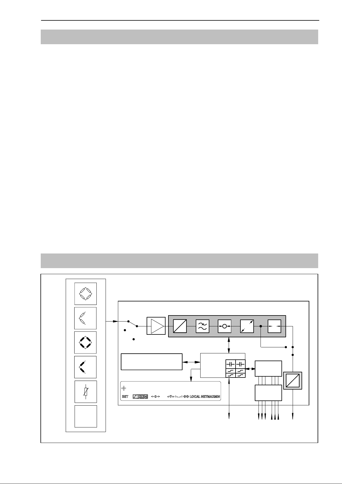
1.3 Block diagram
Measure
Zero
parameter memory
Connectable transducer
Cal.
data set 1...8
127,533 KN
A
D
CPU
E
T
control
signal
D
A
optical
coupler
LVDT
Fig. 1.1: SCOUT 55 block diagram
RS232
...
5 outputs/
6 inputs
U
A/IA
HBMA0236-5.9 en
Page 12
12
Scout 55
2 Connections
Observe the safety instructions before commissioning the device.
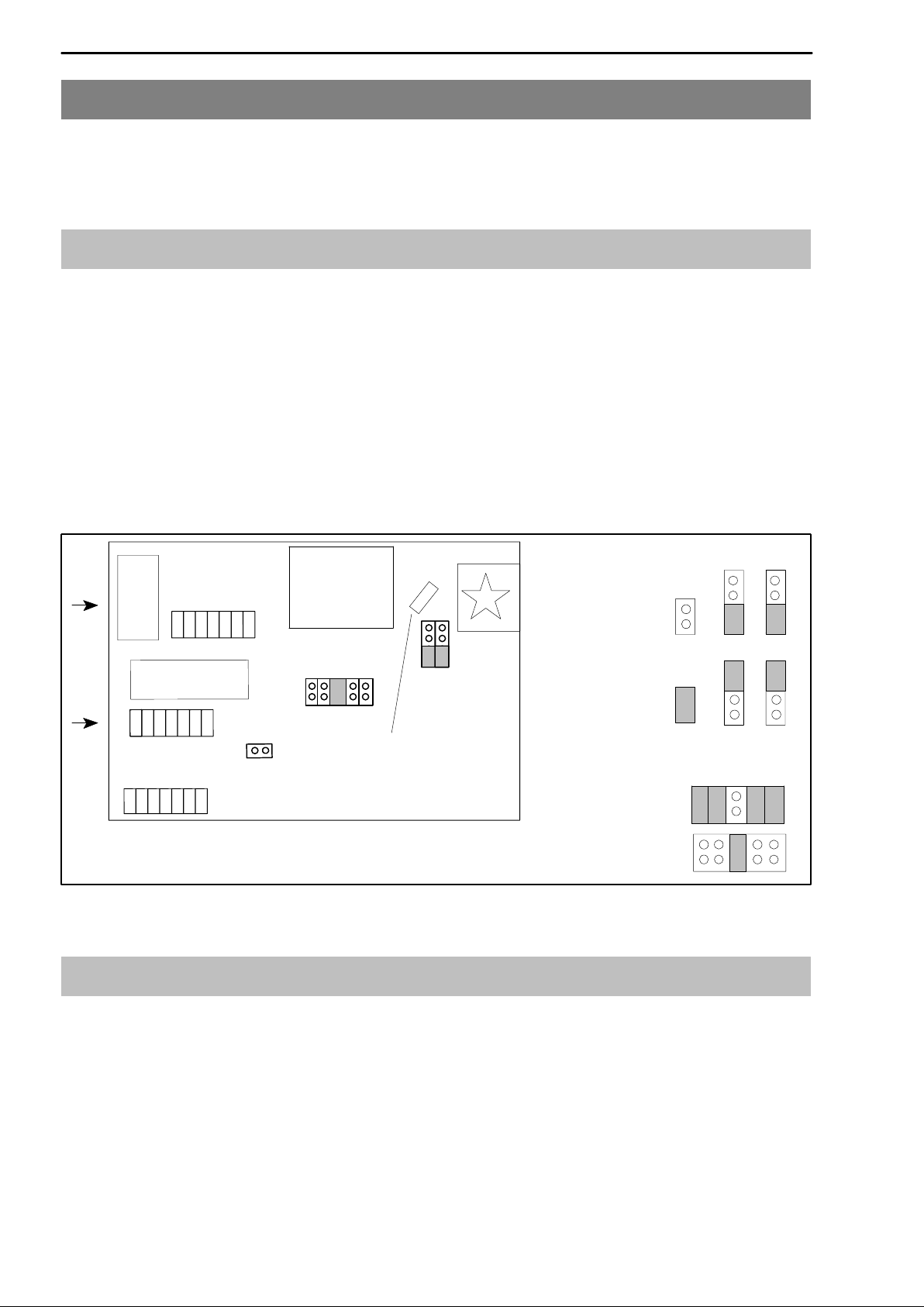
2.1 Factory settings
Before operating the device, check the parameters set at the factory and note
that the elements for selecting the analogue output signal (current/voltage
output) and for setting synchronisation, are located on the motherboard.
The factory settings are given below:
D Mains voltage: 230 V / 50...60 Hz or 115 V / 50..60 Hz, depending on order
D Analogue output: output voltage "10 V
D Synchronisation: master
IC
Frontsite
ST100: for attaching spare bridges
ST9 and ST10: for options
ST9
IC
ST10
ST13
ST100
Transformer
ST11
Fuses (slow-blowing)
ST15
ST14
Fig. 2.1: Location of jumpers on motherboard
2.2 Changing the factory settings
Master/Slave setting:
Master:
ST13
Slave:
ST13 ST14 ST15
Analogue output:
Current
ST11
Voltage
ST11
ST14 ST15
To change the factory settings, proceed as follows:
1 Switch off the device and take out the mains cable. Remove all the plug
connections on the back panel.
2 Loosen the four screws on the cover of the housing and remove the cover.
3 Change whichever setting is relevant to you with the aid of the jumpers, by
following Fig. 2.1
4 Screw the cover of the housing back in position.
HBM A0236-5.9 en
Page 13
Scout 55
13
2.2.1 Setting the analogue output signal
Select the analogue output signal (voltage or current) by replugging jumpers
ST11 (see Fig. 2.1). Choose between "20 mA or 4...20 mA in the control
dialogue.
2.2.2 Choosing the operating mode for synchronisation
To synchronise several devices, set one device as the Master. All the other
devices should then set to Slave. The “Master” and “Slave” selections are
made with jumpers ST13, ST14 and ST15 (see Fig. 2.1).
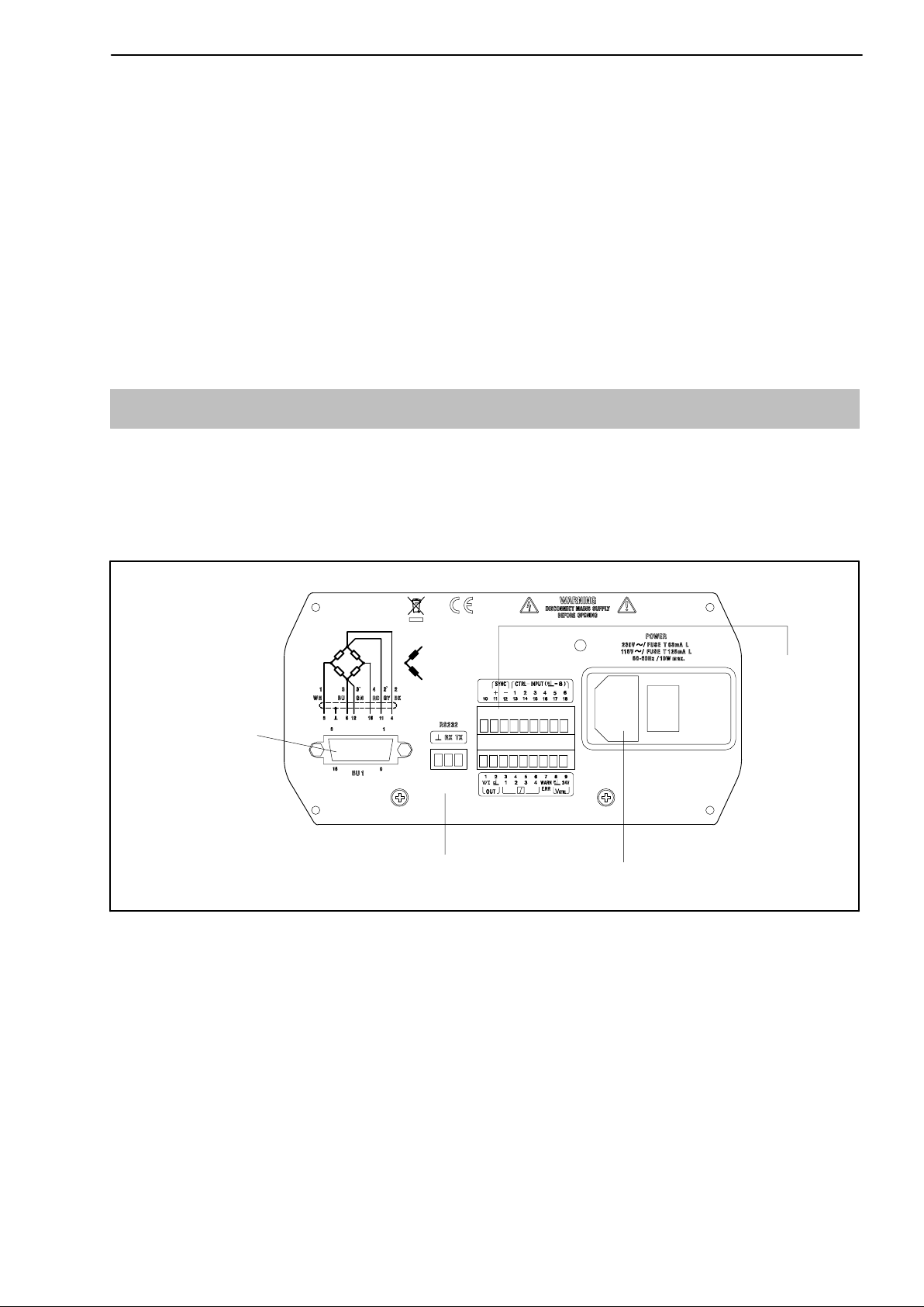
2.3 Connecting the voltage supply
Check that the mains voltage of the device (details on the back of the device)
matches the supply voltage. If this is not the case, change the device setup as
described under 2.3.1 .
transducer
connection
(15-pin
female
connector)
Fig. 2.2: Back of the device
interface port
mains connection
synchro-
nisation
analogue
output
5 outputs/
6 inputs
An inlet connector for non-heating devices is provided for connecting the
mains cable. The requisite mains power supply cable is included in the list of
components supplied.
Country-specific versions are available as accessories.
HBMA0236-5.9 en
Page 14
14
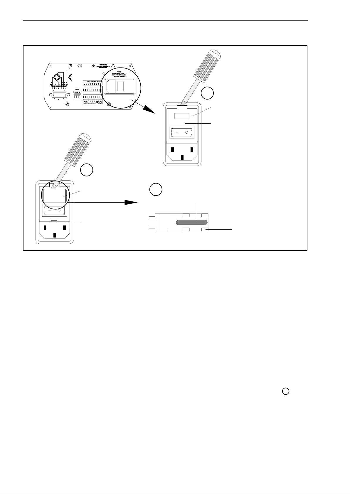
2.3.1 Changing the mains voltage selection/replacing the fuse
1
window
230V
cover
2
Scout 55
230V
PRSR
115V
fuse holder
cover open
3
replace fuse(s)
230 V: T63mA L
115 V: T125mA L
fuse holder
Fig. 2.3: Back of device: choosing mains voltage, replacing fuses
The mains voltage currently selected (e.g. 230 V) is shown in the “window”.
Adapting the mains voltage:
Switch off the device and take out the mains cable.
1 Lever the lid off and fold it aside
2 Remove the fuse holder
− Fit the fuse holder to correspond to the required mains voltage (comply
with the nominal current of the fine-wire fuse)
− Close the cover
2
The chosen mains voltage can be seen in the “window” (selection here
:
230 V).
HBM A0236-5.9 en
Page 15
Scout 55
Replacing the fuses:
Switch off the device and take out the mains cable.
1 Lever off the cover and fold it forward
2 Take out the fuse holder
3 Replace the fuses
− Fit the fuse holder, paying attention to the correct mains voltage (the
chosen value can be seen in the “window”).
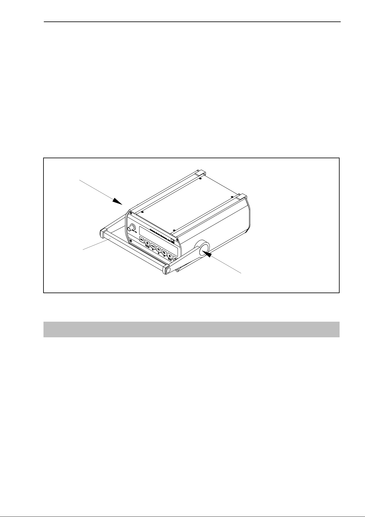
2.3.2 Device mounting
15
mounting frame and
carrying handle
Fig. 2.4: SCOUT 55 mounting
press (on both sides) and
fold down the handle
2.4 Transducer connection
The following transducer types can be connected to the SCOUT 55:
D S.G. full and half bridge transducers
D Inductive half and full bridge transducers
D Potentiometric and piezoresistive transducers
D LVDT (Linear Variable Differential Transformer)
A 15−pin socket on the back panel of the housing, labelled BU1, is used for
connection.
HBMA0236-5.9 en
Page 16
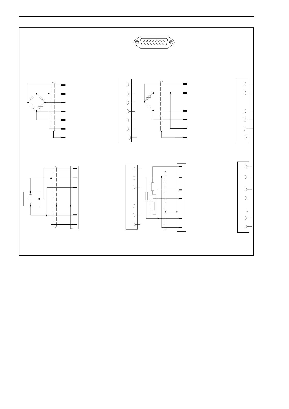
16
Scout 55
BU 1
Transducer connection socket
S.G. and inductive full bridges
piezoresistive transducers
WH
Measurement signal (+)
BK
Voltage (−)
RD
Measurement signal (−)
BU
Voltage (+)
GN
Sensor circuit (+)
GY
Sensor circuit (−)
YE
Cable shielding
potentiometric transducer
Measurement
signal (+)
Voltage (−)
8
5
15
6
13
12
Case
8
15
1
9
S.G. and inductive half bridges
Measurement
WH
signal (+)
BK
Voltage (−)
BU
Voltage (+)
GN
Sensor circuit (+)
GY
Sensor circuit (−)
YE
Cable shielding
8
5
6
13
12
Case
LVDT-transducer
8
5
Measurement signal (+)
Voltage (−)
8
5
2
1
3
Voltage (+)
Cable shielding
Sensor circuit (+)
Sensor circuit (−)
6
Case
13
12
Voltage (+)
Measurement signal (−)
Cable shielding
Sensor circuit(+)
Sensor circuit(−)
15
Case
13
12
Wire colours: WH= white; BK= black; BU= blue; RD= red; YE= yellow; GN= green;
GY= gray
Fig. 2.5: Connecting various transducers
6
HBM A0236-5.9 en
Page 17
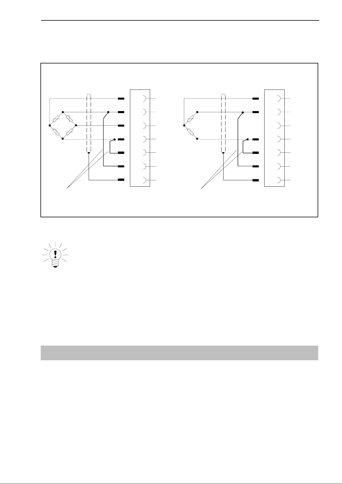
Scout 55
When connecting a transducer with a four-wire cable, you must connect the
sensor circuits with the relevant bridge excitation circuit in the male cable
connector (pin 5 with pin 12 and pin 6 with pin 13).
17
Four-wire connection: full bridge
WH
BK
RD
BU
YE
feedback bridges in the transducer cable plug
Wire colours: WH= white; BK= black; BU= blue; RD= red; YE= yellow; GN= green; GY= gray
8
5
15
6
13
12
Case
Four-wire connection: half bridge
WH
BK
BU
GN
GY
YE
8
5
15
6
13
12
Case
Fig. 2.6: Transducer connection in four-wire technique
NOTE
To connect the transducers, use HBM standard cable. If you use another
shielded, low-capacitance measurement cables, connect the shielding of
the transducer cable to the connector housing, in accordance with HBM
Greenline information (see http://www.hbm.com/Greenline). This
guarantees EMC protection.
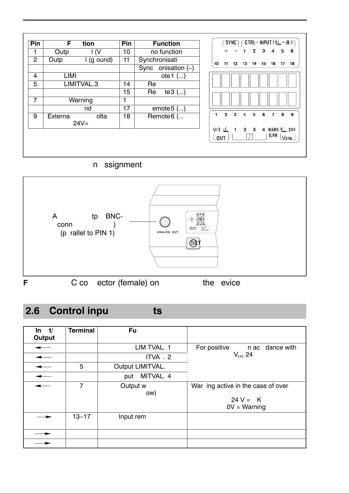
2.5 Analogue output
The analogue output signal is available as voltage ("10 V) or as current
("20 mA or 4.. 20 mA) at terminals 1 and 2. The output voltage is also
available at the BNC connector (female) on the front of the device (see
Fig. 2.8.)
To choose current or voltage, use the jumpers on the amplifier motherboard,
as described in Chapter 2.1.
HBMA0236-5.9 en
Page 18
18
Á
Á
Á
Á
Á
Á
Á
Á
Á
Á
Á
Á
Á
Á
Á
Á
Á
Á
Á
Á
Scout 55
Pin
1
2
Output signal (ground)
3
4
5
6
7
8
9
External supply voltage
ББББББББ
Function
Output signal (V/I)
LIMITVAL.1
LIMITVAL.2
LIMITVAL.3
LIMITVAL.4
Warning
Ground
24V=
Pin
10
11
12
13
14
15
16
17
18
БББББББ
Fig. 2.7: Output pin assignment
Function
no function
Synchronisation (+)
Synchronisation (−)
Remote1 (...)
Remote2 (...)
Remote3 (...)
Remote4 (...)
Remote5 (...)
Remote6 (...)
Analogue output BNC-
connector (female)
(parallel to PIN 1)
SET
Fig. 2.8: BNC connector (female) on the front of the device
2.6 Control inputs / outputs
Input/
Output
ÁÁÁÁ
ÁÁÁÁ
ÁÁÁÁ
ÁÁÁÁÁÁÁ
Terminal
ÁÁ
3
4
5
6
7
ÁÁ
ÁÁ
13−17
8
9
Function
БББББББББ
Output LIMITVAL. 1
Output LIMITVAL. 2
Output LIMITVAL. 3
Output LIMITVAL. 4
Output warning
БББББББББ
БББББББББ
БББББББББ
(overflow)
Input remote1−6
(function selectable)
Ground
External supply voltage
ББББББББББББ
For positive logic in acordance with
ББББББББББББ
ББББББББББББ
ББББББББББББ
V
Warning active in the case of overflow,
ББББББББББББ
ББББББББББББ
ББББББББББББ
Autocal and MOTION OUT
24 V = OK
0V = Warning
see table on Page 45
V
V
ext.
ext.
ext.
24 V
0 V
24 V
HBM A0236-5.9 en
Page 19
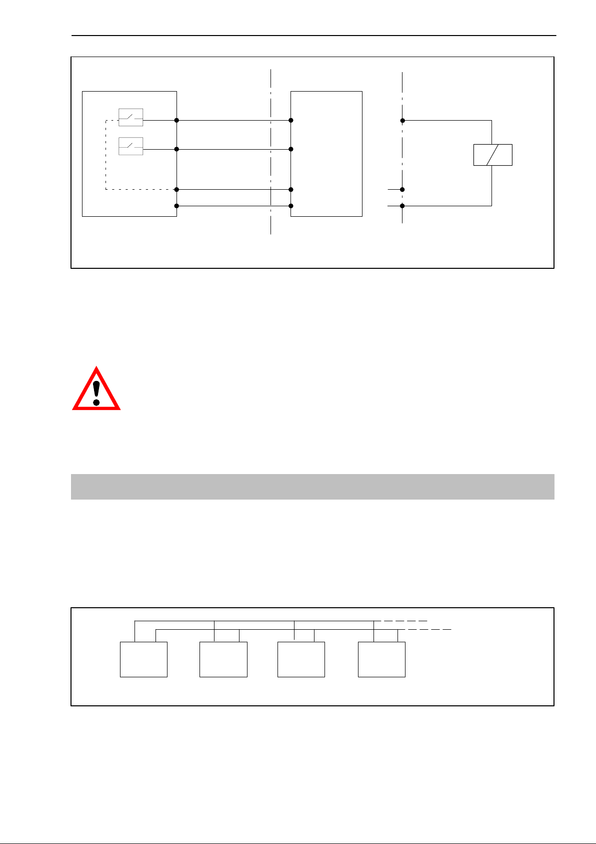
Scout 55
19
SCOUT 55 PLC
6
9
8
max. 0.5A
24V*
0V
external supply voltage of the
relay
max. 0.5A
24V*
0V*
control outputs
Fig. 2.9: Output assignments
* The control inputs and outputs are available at the terminal strip socket
(9−pin) and are potential-separated by optical couplers. The control outputs
must be supplied with an external voltage (ground
and 24 V).
If the mains voltage is switched off, there is a power failure, or the mains
fuse blows, all the control outputs are reset to 0V (V
ext.
).
2.7 Synchronisation
If several devices are used right next to one another or if their cables run
parallel, the devices should be synchronised. To achieve this, one device
must be set to Master and all the others (max. seven) to Slave. The setup with
jumpers on the amplifier motherboard is described in Chapter 2.2.2 . As well
as these settings, the devices must be linked together for synchronisation.
11 12 11 12 11 12 11 12
Master Slave Slave Slave
Device 1 Device 2 Device 3 Device 4 (...max. 7)
Fig. 2.10: Terminal connections for synchronisation
HBMA0236-5.9 en
Page 20

20
Scout 55
2.8 Connecting the serial interface
On the back of the device, there is an RS232 serial interface for connecting a
computer or a terminal.
When connecting a printer, a simple line printer needing no
more than 4 seconds to print a line is sufficient. The printout
has 12 columns. This corresponds to a line length of 132
characters. Select the measured values to be printed as
described in Chapter 3.5.9.
When connecting a computer, it is possible to enter into dialogue with the
SCOUT 55.
You can use control commands to make all the device settings and query the
measured values. An overview of the interface commands has been compiled
in another part of the Operating Manual “SCOUT 55, Part2: Operation by
computer or terminal”.
3 Setting up and operation
3.1 Commissioning and factory settings
Some of the steps you need to take to commission your measurement chain
(amplifier and transducer) are listed below, so that you can carry out an initial
function test of all components. The description basically covers adapting the
SCOUT 55 to the transducer type used. We also warn about certain errors
which can typically occur during commissioning.
D Follow the steps given in the previous Chapter to connect the mains cable
and the transducer to the measuring amplifier.
Please observe the safety instructions
D Turn on the power switch.
D The device runs a function test and is then in measuring mode. The factory
settings are active.
D Check the choice of output signal shown on the display. Use
the gross signal (no labelling in the display)
HBM A0236-5.9 en
to select
Page 21

Scout 55
21
NOTE
If the error message CALERR. appears here, the following can be the
causes:
− no six-wire feedback connected
− incorrect transducer/sensor connection
− no transducer/sensor connected
Remedy:
Switch off the device. Connect the transducer properly. Switch the device
back on. If the error message OVFL B, OVFL N appears, you must adapt the
measuring amplifier to your transducer type. The steps to take for each
amplifier are described below.
D To get from measuring mode to device setup mode, press
SET
for about
2s. “DIALOG” will appear in the display.
D Follow the examples given below to adjust the device according to the
connected transducer type.
Transducer types:
S.G. force transducer:
Adaptation:
Transducer type: Full bridge
Excitation: 2.5 V
Input: 4 mV/V
Calibration:
Unit, nominal value/
decimal point: 20,000 kN
Measuring range: 2 mV/V
Inductive displacement transducers:
Adaptation:
Transducer type: Half bridge
Excitation: 1.0 V
Input: 10 mV/V
Calibration:
Unit, nominal value/
decimal point: 20,000 mm
Measuring range: 10 mV/V
HBMA0236-5.9 en
Page 22

22
Piezoresistive transducers:
Adaptation:
Transducer type: Half bridge
Excitation: 2.5 V
Input: 400 mV/V
Calibration:
Unit, nominal value/
decimal point: 30,000 BAR
Measuring range: 200 mV/V
Potentiometric transducers:
Adaptation:
Transducer type: Half bridge
Excitation: 1 V
Input: 1000 mV/V
Scout 55
Calibration:
Unit, nominal value/
decimal point 10,000 mm
Measuring range: 1000 mV/V
HBM A0236-5.9 en
Page 23

Scout 55
23
Key to symbols
Group
Parameter
old setting
new value
MEAS. MODE
SET
DIALOG
PAR
press for 2 sec
select number
change value
LANGUAGE
ENGLISH
DEUTSCH
SET
Language
press once
ADAPTATION
Continued on next page
transducer adaptation
HBMA0236-5.9 en
Page 24

24
Scout 55
S.G. force
transducer
(= factory settings)
PAR
TRANSDUCER
LVDT
FULL BRG.
PAR
Inductive
displacement
transducer
Transducer type
Piezoresistive transducer Potentiometric
transducer
HALF BRG.HALF BRG.
HALF BRG.
EXCITATION
1V
2.5 VOLT
PAR
INPUT
400mV/V
4 mV/V
Setting the excitation voltage
1.0 VOLT
Input signal
10 mV/V
2.5 VOLT
400mV/V
1.0 VOLT
1000mV/V
SET
CALIBR.
press once
change group
Amplifier adjustment
Continued on next page
HBM A0236-5.9 en
Page 25

Scout 55
25
S.G. force
transducer
(= factory settings)
PAR
UNIT
....
Measured quantity unit
kN
PARPAR
Inductive
displacement
transducer
....
mm
Piezoresistive
transducer
....
BAR
Potentiometric
transducer
....
mm
NOM. VALUE
....
20000 kN
PAR
dEc.P
RANGE
....
2,00000 mV/V
Nominal value input
....
20000 mm
....
30000 BAR
....
10000 mm
Press four times (skip decimal point, digit step, zero value)
Range
....
10 mV/V
....
200 mV/V
....
1000 mV/V
HBMA0236-5.9 en
Page 26

26
Scout 55
Switch to measuring mode
SET
Press for 2s
SAVE
SET
The settings are saved in parameter set 1 and the device switches to
measuring mode.
You can now run an initial function test.
NOTE
The settings are only power fail safe once they have been saved under
one of the parameter sets.
HBM A0236-5.9 en
Page 27

Scout 55
3.2 Control concept and functional overview
The control concept makes a distinction between two types of button
functions:
− keys that are operative during measuring mode and
− keys effective in programming mode.
Measured
value display,
parameter
presentation
27
Button row
operating
SET
Change
operating
mode/ choose
group
SET
Change
mode
Set
limit
values
Parameter
selection
Measuring mode
TareZero
Programming
Display of
set value/
choice of
number
CL
CL
Clear
stores
Selection buttons
Change parameter/
numeric value
Print
Switch
display
Input
signal
measurement
Confirm
Key to symbols:
Sign
Limit switches (come
on when operating,
flash in setup mode)
flashes in programming mode
Zero done (only comes
on if the zero value is not
000000mV/V)
standstill
indication
Tare done (only
comes on if the
contents of the
tare buffer are not
000000)
interface
activ
Keyboard
operation
only
Signal indicator
HBMA0236-5.9 en
Page 28

28
3.3 Button functions in measuring mode
Key Meaning
Scout 55
SET
CL
Change from Measuring mode to Programming mode (and vice
versa) by pressing
for approx. 2s.
Set the limit values LV1...4 (see from Page 41)
The additional parameters of the limit switches such as
hysteresis, direction etc., are unchanged. The limit value
function can be activated in the LIMITVAL.1...4 menu
(see Page 41).
Zeroing the measurement chain (also possible by remote).
The signal at the input is applied as the zero point.
Taring the measured value (also possible by remote).
The current measured value is applied as the tare value.
Deletes the contents of the peak value store (also possible by
remote). This function applies to all peak value stores (Min,
Max, Peak-to-Peak).
Output of measured values and parameters over the RS-232
interface (also possible by remote).
For possible print parameters, see “Additional function” starting
on Page 47.
Only those parameters (PRINT xxx) selected in additional
functions will be printed.
Switches the measured value display between:
Gross value no marking in the display
Net value (=gross minus tare) “NET” is displayed
Minimum value “MIN” is displayed
Maximum value “MAX” is displayed
Peak-to-peak value “MAXMIN” is displayed
3.3.1 Querying and setting limit values in measuring mode
You have several options available when choosing the limit values (in
measuring mode):
a: Numerical value entry for limit values
b: Apply input signal as limit value
c: Fast search (keep arrow keys pressed for several seconds)
HBM A0236-5.9 en
Page 29

Scout 55
29
MEAS. MODE
LV1 LEVEL (LIMITVAL.1)
The current limit value is displayed.
Numerical value entry for
limit values (LV1 LEVEL)
Proceed in the same way for LV2 to LV4
Save changes power
fail safe
Apply input signal
as limit value
MEA
S
SET
Press for 2 sec,
SAVE is displayed
SAVE DONE is displayed
Fast run
Keep pressed
SET
LV1 to LV4 are saved power fail safe;
the device switches to measuring mode
HBMA0236-5.9 en
Page 30

30
Scout 55
3.4 Button functions in programming mode
In this operating mode, you can make all the settings for using the amplifier in
your application. The parameters are collected into groups.
Meaning of the keys:
SET
PAR
MEAS
Change mode (press for 2 sec), select group (e.g. CALIBR.)
Parameter selection (e.g. NOM. VALUE)
Display last value set.
Select desired number.
Changes the number in ascending order.
Changes the number in descending order.
Apply measured value.
Confirms input/modification
3.4.1 Changing from “Measuring” mode to “Programming” mode
SET
Press for 2s
DIALOG
HBM A0236-5.9 en
Page 31

Scout 55
3.4.2 Programming
Typical programming mode operations
31
Selecting the value/parame-
ter from a given table (exam-
ple DIALOG-LANGUAGE)
SET
DIALOG
PAR
**
LANGUAGE
Entering a numerical value as
a parameter (example CAL-
IBR./
RANGE)
SET
CALIBR.
PAR
RANGE
Apply a signal produced by the
transducer when a defined load-
ing occurs
SET
CALIBR.
PAR
*
MEAS
ENGLISH
DEUTSCH
Only possible when setting the zero value, the measuring range
*
and the limit values
see page 37
* *
. . . .mV/V
0.60000 mV/V
. . . .mV/V
2.000 mV/V
HBMA0236-5.9 en
Page 32

32
Scout 55
3.4.3 Switching from “Programming” operating mode to “Measuring”
operating mode
When the parameters are changed, you will be asked whether the modified
parameters are to be saved power fail safe.
SET
Press for 2s
SAVE
SET
Not saved power fail safe
SAVE DONE
SET
Measuring mode Measuring mode
Saved power fail safe in
current parameter set
NOTE
The settings are only power fail safe once they have been saved under
one of the parameter sets.
HBM A0236-5.9 en
Page 33

3.5 Overview of all groups and parameters
PARAM
Parameters
SET
Groups
DIALOG PARAM. SET ADAPTATION CALIBR. LIMITVAL.1...4 PV STORE IN/OUT ADD. FUNCT.
LANGUAGE RECALL TRANSDUCER UNIT ENABLE ENABLE SOURCE UA P34
PASSWORD SAVE ? EXCITATION NOM. VALUE SOURCE PVS1 MODE UA SERIAL No.
BUTT. LVS
BUTT. ZERO AUTOCAL STEP LEVEL ENVELOPE CONTACT 1 PARITY
BUTT. TARE
BUTT. PVS MOTION CNT RANGE LOGIC CONTACT 3 COMM. ADDR
BUTT. PRINT MOTION DIG TARE VALUE LV BUTT
BUTT. SIGN MOTION OUT SET SET CONTACT 5
1)
SET
SET
INPUT
FILTER ZERO VALUE HYSTERESIS SET CONTACT 2 STOPBITS
SET CONTACT 6 PRINT MAX
DEC. POINT SWITCH DIR. PVS2 INPUT SIGN. BAUDRATE
CONTACT 4
REMOTE PRINT MIN
SET PRINT PP
PRINT.GROSS
PRINT NET
PRINT LVS
PRINT OVERL
PRINT PAR.
ZERO/TARE
SET
1)
a0236−5.9 en SCOUT 55
Use
SET
to next group
33
Page 34

3.5.1 Setting all parameters
2sec
SET
Password
00000
34
SCOUT 55
+0000 CODE
_ _ _ _
continue with
DIALOG
Enter password
+
press twice
NOYES
DIALOG
PARAM
LANGUAGE
PASSWORD
BUTT. LVS
BUTT. ZERO
BUTT. TARE
BUTT. PVS
BUTT. PRINT
BUTT. SIGN
SET
DEUTSCH
ENGLISH
FRANCAIS
ITALIANO
ESPANOL
+0000 CODE
0000
ENABLED
LOCKED
Groups
PARAM. SET
PARAM
RECALL
SAVE ?
SET
to next
group
adaptation
PARASET 1
PARASET 2
PARASET 3
PARASET 4
PARASET 5
PARASET 6
PARASET 7
PARASET 8
FACT. SETUP
PARASET 1
PARASET 2
PARASET 3
PARASET 4
PARASET 5
PARASET 6
PARASET 7
PARASET 8
FACT. SETUP
a0236-5.9 en
SET
to next
group
Parameter values
Select parameter
SET
Flashes if parameter value can
be edited
Confirm input:
Back to measuring mode
press
SET
2sec
Page 35

SCOUT 55
parameter set
groups
PV STORE
ADAPTATION
PARAM
TRANSDUCER
EXCITATION
INPUT
AUTOCAL
FILTER
MOTION CNT
MOTION DIG
FULL BRG.
HALF BRG.
LVDT
2.5 VOLT
1.0 VOLT
4 mV/V
40 mV/V
400 mV/V
OFF
ON
ONCE
400 HZ BE
200 HZ BE
100.0 HZ BE
40.0 HZ BE
20.0 HZ BE
10.0 HZ BE
5.0 HZ BE
2.5 HZ BE
1.25 HZ BE
0.5 HZ BE
0.2 HZ BE
0.1 HZ BE
0.05 HZ BE
500 HZ BU
200.0 HZ BU
80.0 HZ BU
40.0 HZ BU
20 HZ BU
10 HZ BU
5.0 HZ BU
+000 MEAS
+000 000 V
CALIBR.
PARAM PARAM
UNIT
NOM. VALUE
DEC. POINT
STEP
ZERO VALUE
RANGE
TARE VALUE
SET
to next
group
+010 000 V
FIX
.000
FIX
1
2
5
10
20
50
100
200
500
+0.00000mV/V
+2,0000mV/V
+000,000 V
G
KG
T
KT
TON
LB
OZ
N
KN
BAR
mBAR
PA
PAS
HPAS
KPAS
PSI
mm
mm
cm
m
INCH
Nm
KNm
FTLB
INLB
mm/m
M/S
M/SS
%
‰
PPM
S
MP
MN
mV/V
V
A
mA
LIMIT VALUE*) 1...4
SWITCH DIR.
HYSTERESIS
ENABLE
SOURCE
LEVEL
LOGIC
LV BUTT
SET
to next
group
OFF
OFF
ON
ON
GROSS.VALUE
NET VALUE
PVS1 MAX
PVS2 MIN
PVS3 PP
LOWER
HIGHER
+000,000 V
+000,000 V
ACTIVE.HIGH
ACTIVE.LOW
ENABLED
LOCKED
MOTION OUT
SET
OFF
ON
to next
group
*)
Query and set limit values in measuring mode, see Page 28
35
a0236-5.9 en
Page 36

36
LIMITVAL.1...4
PV STORE
PARAM
ENABLE
PVS 1 INPUT
PVS 2 INPUT
ENVELOPE +000. 000 S
SET
to next
group
PVS OFF
PVS ON
GROSS.VALUE
NET VALUE
GROSS.VALUE
NET VALUE
IN/OUT
SOURCE UA
MODE UA
INPUT SIGN.
CONTACT 1
CONTACT 2
CONTACT 3
CONTACT 4
CONTACT 5
CONTACT 6
REMOTE
Groups
GROSS.VALUE
NET VALUE
PVS1 MAX
PVS2 MIN
PVS3 PP
10 VOLT
UA OFF
MEAS.SIGNAL
ZEROSIGNAL
CAL SIGNAL
GROSS / NET
NO FUNCT.
AUTOCAL
TARE
PVS1 INST
PVS1 HOLD
PVS2 INST
PVS2 HOLD
ZEROING
PRINT
PARACODE 1
PARACODE 2
PARACODE 3
BUTTON.LOCK
ON
OFF
ADD. FUNCT.
PARAMPARAM
P34
SERIAL NO.
BAUDRATE
PARITY
STOPBITS
COMM. ADDR
PRINT.GROSS
PRINT NET
PRINT MAX
PRINT MIN
PRINT PP
PRINT LVS
PRINT OVERL
SCOUT 55
9600 BAUD
4800 BAUD
2400 BAUD
1200 BAUD
600 BAUD
300 BAUD
EVEN PAR.
NO PAR.
ODD PAR.
1 STOPBIT
2 STOPBIT
+00 ADDR
ON
OFF
a0236-5.9 en
SET
to next
group
PRINT PAR.
ZERO/TARE
SET
START
SAVE OFF
SAVE ON
DIALOG
Page 37

Scout 55
37
3.5.2 Dialogue
Select language (LANGUAGE)
Factory settings: DEUTSCH
You can choose the following languages:
German (DEUTSCH), English (ENGLISH), French (FRANCAIS),
Italian (ITALIANO), Spanish (ESPANOL)
3.5.3 Load/Save in parameter set (PARAM. SET)
The current device amplifier settings can be saved power fail safe in eight
parameter sets
and later queried.
When switching from the programming operating mode to measuring mode,
you will be asked whether or not the change is to be saved. This is described
in Chapter 3.4.3 .
Parameter sets can also be activated/recalled by remotes (PARACODE1...2,
see Chapter 3.5.8).
RECALL: Parameter set 1 (parameter set 1...8) and factory
setting (FACT. SETUP) are loaded
SAVE: Save as parameter set 1...8
3.5.4 Adaptation
TRANSDUCER:
Depending on the type of transducer, you can choose between the following
bridge types:
Selectable bridge types
*)
No distinction is made here between transducers with strain gauges and inductive transducers
Full bridge
*)
Half bridge
*)
LVDT
HBMA0236-5.9 en
Page 38

38
EXCITATION:
The excitation voltage for the transducer is selected.
Scout 55
Selectable excitation voltages
1 V 2.5 V
INPUT:
Depending on which excitation voltage is chosen, the input range
(approximate measuring range) can be selected for the transducer type.
Input range UB = 2.5 V UB = 1 V
I "4 mV/V "10 mV/V
II "40 mV/V "100 mV/V
III "400 mV/V "1000 mV/V
AUTOCAL:
Depending on the application and on the stability requirement, you can start
an autocalibration cycle. This lets you correct zero point and full scale value
drift and the long-term constancy of the measuring amplifier.
Possible settings:
ON Autocalibration switched on
OFF Autocalibration switched off
ONCE
Autocalibration is run once, as soon as you confirm it with
Autocalibration stays on/off, depending on the state previously
selected.
CAUTION
If you need the analogue output signal for continuous monitoring, you
must switch autocalibration off.
Reason: no measured values are recorded during the autocalibration
cycle. This produces a “monitoring gap” (interval approx. 5 min.,
duration approx. 1s), which is undesirable if not dangerous during
production processes.
HBM A0236-5.9 en
Page 39

Scout 55
FILTERS:
Different low-pass filters (characteristics and cut-off frequencies) can be
selected:
Characteristics
Bessel (BE)
(Hz)
0.05 18.75 5.0 1200
0.1 37.5 10 1200
0.2 75 20 1200
0.5 300 40 1200
1.25 600 80 1200
2.5 1200 200 1200
5.0 1200
10 1200
Sampling rate
(measured
values per sec)
*)
Butterworth (BU)
(Hz)
Sampling rate
(measured values
per sec)
*)
39
20 1200
40 1200
100 1200
200 1200
*) see motion count (MOTION CNT)
MOTION CNT (motion count)
To activate the motion count, you must set the number of measurements.
During these measurements, the measured value must fall within the given
tolerance for “standstill” to be reported. (for sampling rate, see table on
Page 39).
Settings
+000 MEAS Motion count switched off
+255 MEAS Maximum possible number of measurements
MOTION DIG
Input of tolerance field in digits in display units.
000110 kN
MOTION OUT
Output of motion count status (control output terminal 7; warning).
Possible settings:
OFF The motion count status is not output over WARNING
ON WARNING active, if no standstill or device error
HBMA0236-5.9 en
Page 40

40
Scout 55
Display
units
t
24V
Warning
0V
Fig. 3.1: Effect of the motion count
3.5.5 Calibration (CALIBR.)
UNIT
You can select the following units:
Selectable unit
Tolerance field (MOTION DIG)
Time
Standstill
(number of measurements
within time interval t)
N S cm
OZ PPM mm
LB ‰ mm
TON % PSI
KT M/SS KPAS
T M/S HPAS
KG mm/m PAS
G INLB PA
V FTLB mBAR
mV/V KNm BAR
MN Nm KN
MP INCH A
−−−− m mA
NOM. VALUE
You can adjust the nominal value. Specify the nominal value including the
desired decimal places.
Examples:
a. You want to measure in a pressure range between 0 and 1000.00 bar.
Enter nominal value: 100000
b. With a 50 kg load cell you want to display the measured value with 3
decimal places.
Enter nominal value: 50000
HBM A0236-5.9 en
Page 41

Scout 55
DEC. POINT
Changes the position of the decimal point.
41
Selectable positions
.0000 0.000 00.00 000.0 0000
For above example a: .00
for above example b: .000
STEP
You can choose the step or the digit step.
Selectable steps
1 2 5 10 20 50 100 200 500 1000
ZERO VALUE
The maximum zero balance range matches the particular maximum
measuring range in the following table.
RANGE:
Sets a full scale value (unit mV/V). If this value lies outside the input range,
the minimum or maximum possible value is accepted.
Input range Range at UB = 2.5V Range at UB = 1V
I "0.2...4 mV/V "0.5...10 mV/V
II "2...40 mV/V "5...100 mV/V
III "20...400 mV/V "50...1000 mV/V
TARE VALUE:
You can specify a tare value (in display units) (net value = gross value minus
tare value).
3.5.6 Limit values 1...4 (LIMITVAL.1...4)
The parameters for setting the limit values are combined in a group for each
limit value. The status of the limit switches is shown on the display and carried
out over the control outputs.
The function of the limit switches and their parameters are shown in the
following diagram:
Over limit
Below limit
LV1 ACTIVE.HIGH
LV2 ACTIVE.HIGH
24V
0V
24V
0V
Gr1
Switching on
Switching on
Gr2
Switching off
switching level
Hysteresis value
Switching off
Hysteresis value
switching level
Fig. 3.2: Limit value functions and parameters
HBMA0236-5.9 en
Page 42

42
ENABLE
Scout 55
OFF
ON
Disable individual limit switches
Enable individual limit switches
SOURCE
Limit value evaluated.
GROSS.VALUE
NET VALUE
PVS1 MAX
PVS2 MIN
PVS3 PP
SWITCH DIR.
Store for maximum values
Store for minimum values
Store for peak-to-peak value
Gross
Net
Specify the switch direction or the working direction here (see Fig. 3.2).
HIGHER
LOWER
Switch-on level greater than switch-off level for rising measured value
Switch-off level greater than switch-on level for falling measured value
LEVEL
The level is set in display units (e.g. 2,000kg).
HYSTERESIS
The hysteresis value prevents “fluttering” of the limit switches upon reaching
the switching threshold. Hysteresis is the difference between the activation
and deactivation thresholds.
The value is set in display units, e.g. 0.200kg.
LOGIC
You can change the output logic of the remotes as required. The following
allocation was made:
ACTIVE.HIGH
ACTIVE.LOW
Switched on = High
Switched off = Low
Switched on = High
Switched off = Low
3.5.7 Set peak value store (PV STORE)
Two peak value stores are available to you for monitoring processes. The
following allocation has been made:
PVS1
PVS2
HBM A0236-5.9 en
Store for maximum values
Store for minimum values
Page 43

Scout 55
Use key to display Max/Min values in measure mode.
An additional value is determined arithmetically.
43
PVS3
Store for peak-to-peak value
Linking with PVS1 regarding control functions and envelope.
Both can be operated as peak value stores or as instantaneous value stores.
The choice of operating mode is made with the remotes (see Page 45).
PVS1 INST
PVS1/Hold
PVS2 INST
PVS2/Hold
Instantaneous value or peak value for SP1
Run / Hold mode for SP1
Instantaneous or peak value for PV2
Run / Hold-Modus für SP2
The following diagram shows the function of the remotes:
Measurement signal
Vi,
V
o
Course of the
store value
t
Function
Operating mode
Peak-value (PVS1)
HoldRun Run
Current value
Hold
Fig. 3.3: Function of the remotes shown in the example of PVS1, peak value
and instantaneous value storage (also applies to PVS2 and PVS3).
If the stores are operated as peak value stores, it is possible to display an
envelope function by enabling and setting a discharge rate. This discharge
rate affects all peak value stores.
Discharge rate: too highDischarge rate: too lowDischarge rate: good
Fig. 3.4: Envelope function
HBMA0236-5.9 en
Page 44

44
You can set the following parameters:
ENABLE:
You can enable or lock the peak value stores.
Scout 55
PVS ON
PVS OFF
peak-value memory/buffer/store locked
Enable peak value store
PVS1 INPUT:
Choice of input signal for peak value store PVS1.
GROSS.VALUE NET VALUE
PVS2 INPUT:
Choice of input signal for peak value store PVS2.
GROSS.VALUE NET VALUE
ENVELOPE CURVE:
You can choose the discharge rate of the envelope function for both the peak
value stores. The specification corresponds to a time in ms.
00000 s
000.100 to 060.000 s
envelope function off
envelope function on
3.5.8 Inputs and outputs (IN/OUT)
In this menu, you can make the required settings for the SCOUT 55 input
signal, the analogue output and the remotes.
SOURCE UA:
The following signals can be specified as the source of the analogue signal:
GROSS.VALUE
NET VALUE
PVS1 MAX
PVS2 MIN
PVS3 PP
Store for maximum values
Store for minimum values
Store for peak-to-peak value
Gross
Net
HBM A0236-5.9 en
Page 45

Scout 55
45
MODE UA:
Depending on the analogue signal you select, the following options are
possible:
Display Meaning
UA OFF −
0 TO 20mA Output "20 mA
4 TO 20MA Output +4.. 20 mA
UA OFF −
10 VOLT Output +/− 10 V
NOTE
The current output or voltage output selection is made using jumpers on
the amplifier motherboard. The procedure is described on Page 45.
INPUT SIGN.:
For test purposes, a calibration signal and a zero signal can be displayed
instead of the measurement signal. You can choose the following input
signals:
MEAS.SIGNAL
CAL SIGNAL *
ZEROSIGNAL *
*)
To display the measurement signal, you must return to measuring mode.
)
)
The display corresponds to 50 % of the current full scale value
Measuring mode
Internal zero point
CONTACT 1...6:
Remotes are available on the connector strip for controlling SCOUT 55
functions. The pin assignment or allocation of the remotes is freely
configurable. No function is defined for the remotes at the factory.
HBMA0236-5.9 en
Page 46

46
Functions Level 0V Level 24V
NO FUNCT. no function (factory setting)
AUTOCAL Autocalibration ON Autocalibration OFF
TARE For the transition 0V − 24 V, the tare value is adopted
Scout 55
PVS1 INST Peak value operating mode for
PV1
PVS1/HOLD Store contents PV1 and PV3 are
updated
PVS2 INST Peak value operating mode for
PV2
PVS2/HOLD Store contents PV2 are
updated
ZEROING For the transition 0V − 24 V, the current instantaneous input signal is
adopted as the zero value
PRINT A printout is triggered over the
GROSS/NET Gross at analogue output Net at analogue output
PARACODE 1 External selection of parameter sets and binary coded
PARACODE 2
PARACODE 3
BUTTON.LOCK ENABLED LOCKED
(see following table)
Instantaneous value operating
mode for PV1
Store contents PV1 and PV3 are
frozen
Instantaneous value operating
mode for PV2
Store contents PV2 are
frozen
interface
inputs
PARAM. SET PARACODE
3 21
1 0 0 0
2 0 0 1
3 0 1 0
4 0 1 1
5 1 0 0
6 1 0 1
7 1 1 0
8 1 1 1
REMOTE
Device control through remotes can be locked or enabled.
ON
OFF
no display Operating using keyboard and remotes
LOCAL Keyboard operation only
HBM A0236-5.9 en
Page 47

Scout 55
47
3.5.9 Additional functions (ADD. FUNCT)
P_ _:
In order to provide better support should you experience technical problems,
the firmware status is indicated by this parameter. If you have any questions
for our service department or HBM branch, giving the existing firmware
version will enable us to provide effective support.
Example: P34 Software version P34
SERIAL NO:
Display the serial number of the device.
BAUDRATE:
You can choose between the following values as the baud rate for the serial
interface.
Selectable baud rates
300 600 1200 2400 4800 9600
PARITY:
The following settings are possible:
Selectable parity
EVEN PAR. ODD PAR. NO PAR.
STOPBITS:
The following settings are possible:
1 STOPBIT
2 STOPBIT
COMM. ADDR*:
Input the device address.
Selectable device addresses 00 to 31
*)
Address selectable only for RS485 version; for RS232, set address to 1
PRINT.GROSS:
Output the gross value over the serial interface.
OFF/ON
PRINT NET:
Output the net value over the serial interface.
OFF/ON
HBMA0236-5.9 en
Page 48

48
PRINT MAX:
Output the maximum value over the serial interface.
OFF/ON
PRINT MIN:
Output the minimum value over the serial interface.
OFF/ON
PRINT PP:
Output the MIN/MAX value over the serial interface.
OFF/ON
PRINT LVS:
Scout 55
Output limit switch states over serial interface.
OFF/ON
PRINT OVERL
Adjust repetition rate. Heading comprising the source of the measured value
and the unit.
0 = no heading (measured value only)
1 = Heading always
10 = Heading every 10 times etc.
PRINT PAR.:
Output all the parameters.
START
NOTE
The chosen print functions (apart from PRINT PAR) are run in measuring
mode (by pressing
HBM A0236-5.9 en
or by remote contact).
Page 49

Scout 55
49
ZERO/TARE:
Any change to the tare value or the zero value made by keys (green) or
remotes, is automatically stored in the current parameter set. This protection
can be switched on or off:
SAVE OFF
SAVE ON
4 Example
The following example uses a measurement task to show you the functionality
of the device and the required settings.
Problem definition:
The forming process in a press is to be monitored in order to obtain uniform
product quality. The maximum force exerted by the press is to be recorded in
each cycle. To guarantee the production process, this maximum force must
fall between the lower (F1) and upper (F2) force limit.
Solution:
The force characteristic measured with an S.G. force transducer (e.g.
C9B/10kN; 1 mV/V) is amplified and evaluated by the SCOUT 55. The peak
value store (maximum) is used to record the maximum force and it is
evaluated with two limit switches with regard to the lower and upper limits. An
additional limit switch is provided for overload protection (emergency shut
down) of the machine.
A PLC takes over the control of the process. As well as the control commands
for the press, it gives the SCOUT 55 a start signal to begin the pressing cycle
and once the process has finished, logically links the limit switch outputs to
the “Good/Bad evaluation”.
The start signal from the PLC clears the contents of the peak value store
through the SCOUT 55 control input. To prevent unintentional modifications,
during measurement, only the “Display signal selection” button is enabled for
the machine operator on site.
The parameter setups are protected against unauthorised modification by a
password.
Device control through the remotes (remote control) must be activated.
HBMA0236-5.9 en
Page 50

50
Wiring diagram:
Scout 55
SCOUT 55 PLC
8/9
Limit3
5
C9B/10kN
PVS1
CONTACT 1 / PVS1 INST
Limit1
Limit2
3
4
13
Serial interface for document printer, host computer, PLC, etc.
Power supply
0 / 24V
Emergency
shutdown
press
Logical
evaluation of
limit values 1
and 2
START
Timing diagram:
Switching state
Start signal from the
PLC (Control 1)
Limit3
Limit2
Limit1
Limit1
Limit2
Contents
of PVS1
Force
characteristic
1
0
1
0
24V
0
PLC evaluation
“ Good ”
HBM A0236-5.9 en
Page 51

Scout 55
Using the PLC to evaluate the limit value message:
Good Reject
Limit1 1 0 1
Limit2 1 1 0
Choose the following settings:
Limit1 Checks whether the lower force limit has been reached.
The input signal is the output of the peak value store
(maximum value). If limit LV1 is exceeded, a High signal is
generated. A positive switch direction must be set with
positive output logic.
Limit2 Checks whether the upper force limit has been reached.
The input signal is the output of the peak value store
(maximum value). If limit LV2 is exceeded, a Low signal is
generated. A positive switch direction must be set with
positive output logic.
51
Limit3 Checks whether the maximum load limit of the machine is
exceeded (emergency shutdown function). The input signal
is the gross measured value. If limit LV3 is exceeded, a
High signal is generated. A positive switch direction must
be set with positive output logic.
PVS1 Records the maximum peak value of the force
characteristic. Must be enabled, the envelope function must
be deactivated. The input signal is the gross measured
value. PVS1 is cleared with remote 1 by switching to
instantaneous value.
Remote 1 Clears the contents of the peak value store. The function
PVS1 INST must be selected. The remote must be
activated.
HBMA0236-5.9 en
Page 52

52
Scout 55
Key to symbols
Group
Parameter
Programming mode
old setting
new value
MEAS. MODE
SET
PAR
press for 2 sec
Dialogue
select number
change value
LANGUAGE
ENGLISH
DEUTSCH
PAR
HBM A0236-5.9 en
Page 53

Scout 55
53
SET
Change group
press twice
ADAPTATION
PAR
TRANSDUCER
LVDT
FULL BRG.
PAR
Transducer
type
Change group
Amplifier adjust-
ment
_ _ _ _
100Hz BE
SET
CALIBR.
PAR
press once
EXCITATION
1V
2.5VOLT
PAR
INPUT
400mV/V
4mV/V
Setting the
excitation
voltage
Input signal
Nominal value input
(display range)
UNIT
....
N
PAR
PAR
dEc.P
NOM. VALUE
Measured
quantity unit
PAR
FILTER
press twice
Signal filter
selection
....
006000N
Continued on next page
HBMA0236-5.9 en
Page 54

54
Scout 55
PAR
DEC. POINT
0000
.
PAR
dEc.P
STEP
Decimal
point input
Digit step input
dEc.P
RANGE
....
00,60000 mV/V
SET
LIMITVAL.1
PAR
Range
Transducer signal
in accordance
with the desired
display range
Change group
Set limit switches
1...4
000000
000005
PAR
ZERO VALUE
MEAS
000000 N
00,0007
Zero value in mV/V
ENABLE
OFF
ON
PAR
SOURCE
NET VALUE
GROSS.VALUE
Limit switch locked
or enabled
Limit value of
different signal
sources
PAR
HBM A0236-5.9 en
Page 55

Scout 55
PAR
55
SWITCH DIR.
LOWER
HIGHER
PAR
LEVEL
dEc.P
0100
+003500 N
Effective direction
Limit value 1
PAR
LOGIC
ACTIVE.LOW
ACTIVE.HIGH
PAR
LV BUTT
Remotes logic
Limit switch
button function
PAR
dEc.P
HYSTERESIS
....
+000005 N
Hysteresis
value input
NET VALUE
ENABLED
SET
Set limit switches 2, 3
and 4 accordingly
HBMA0236-5.9 en
Page 56

56
Change group
SET
press once
SET
Change group
Scout 55
PV STORE
PAR
ENABLE
PVS OFF
PVS ON
PAR
PVS 1 INPUT
Adjusting peak
value stores
Peak value store
locked or enabled
Input signal
choice, store 1
IN/OUT
PAR
SOURCE UA
NET VALUE
GROSS.VALUE
PAR
MODE UA
dEc.P
I/Os
Signal sources
selectable
Set output
signals
NET VALUE
GROSS.VALUE
HBM A0236-5.9 en
OFF
10VOLT
PAR
Page 57

Scout 55
57
INPUT SIGN.
ZEROSIGNAL
MEAS.SIGNAL
PAR
CONTACT 1
NO FUNCT.
PVS1 INST
Input signals
Pin assignment of
remotes 1...6
SET
SAVE
SAVE DONE
SET
press for 2 sec
Query, whether changes
press once
Measuring mode
are to be saved
Save changes
HBMA0236-5.9 en
Page 58

58
5 Error messages
Error message Cause Remedy
FIX The given value cannot be altered.
Example: For unit V and mV/V, the
nominal value setting is fixed at
10,000
OVFL B Gross value overflow
OVFL N Net value overflow
Scout 55
CAL.ERR incorrect transducer/
sensor connection:
No transducer/sensor connected
No six-wire feedback connected
Measuring bridge connected
incorrectly (e.g. full bridge set, but
half bridge connected)
OUTOFRANGE The value chosen for measuring
range, zero point value, nominal
value or tare value cannot be set,
as it exceeds the permissible limits.
DATA ERROR A transmission error occurred when
saving the parameters
Connect the transducer properly.
Switch device off and then back
on again.
The device sets the maximum or
minimum value automatically, as
soon as the error message has
been acknowledged by
“ENTER”.
HBM A0236-5.9 en
Page 59

SCOUT 55
6 Keyword index
59
A
adaptation, 37
aditional functions, 47
autocalibration, 38 , 46
B
baud rate, 47
BNC−connector (female), 18
C
calibration, 40
control inputs− and outputs, 19
D
decimal point, 41
G
gross, 28
gross signal, 20
gross value, 42
H
hysteresis, 41 , 42
I
inductive displacement transducer, 24
inductive transducers, 15
input signal, 44 , 45
inputs/outputs, 44
J
digit step, 41
E
envelope function, 44
error message, 58
F
factory settings, 12 , 20
load/save, 37
filters, 39
four wire technique, 17
full scale value, 41
fuses, 15
jumpers, 12
L
language selection, 37
limit switches, 28
limit value, disable/enable, 42
limit values, 28
setting in measuring mode, 28
logic, 18
LVDT, 15
M
mains voltage selection, 14
Master/Slave, 12
measurement example, 49
measuring mode, 27 , 30 , 32
motion count, tolerance zone, status, 39
HBMA0236-5.9 en
Page 60

60
SCOUT 55
N
net, 28
net value, 42
O
output logic of the remotes, 42
output signal, 44
P
parameter, save, 32
parameter set, 46
load/save, 37
parameters, 33
setting, 34
parity, 47
peak value store, 28 , 42
enable, lock, 44
piezoresistive transducer, 15 , 24
potentiometric transducer, 15 , 24
programming, 31
programming mode, 27 , 30 , 31 , 32
S
S.G. force transducer, 24
S.G. transducers, 15
serial interface, 20
SET, 28
setting parameters, 34
step, 41
stop bit, 47
switch direction, 42
synchronisation, 13 , 19
T
tare value, 41
taring, 28
transducer connection, S.G.-full-and half
bridges, inductive full- and half bridges,
potentiometric transducers, piezoresistive transducers, LVDT, 15
transducer types, S.G.-force transducer,
inductive displacement transducers,
piezoresistive transducers, potentiometric transducers, 21
R
remote, 46
remotes, 43 , 45
replacing the fuse, 14
RS−232 interface, 28
V
voltage output selection, 17
voltage supply, 13
Z
zero balance, 28
HBM A0236-5.9 en
Page 61

Page 62

Page 63

Page 64

pp
Modifications reserved.
All details describe our products in general form only.They are
not to be understood as express warranty and do not constitute
any liability whatsoever.
7-2002.0674
A0236-5.9 en
Hottinger Baldwin Messtechnik GmbH
Postfach 10 01 51, D-64201 Darmstadt
Im Tiefen See 45, D-64293 Darmstadt
Tel.: +49 6151 803-0 Fax: +49 6151 8039100
Email: su
ort@hbm.com Internet: www.hbm.com
 Loading...