

Page 1

Bedienungsanleitung
Operating manual
DMS--Verstärker
RM4220
S.G.--Amplifier
RM4220
A1091--21 de/en
Page 2

Page 3

RM4220
Inhalt Seite
Sicherheitshinweise 5.............................................
1 Anwendung 8..................................................
2 Montage / Demontage 8.........................................
3 Anschluss 9...................................................
4 Konfiguration 1 1................................................
4.1 Anschlussart 11..............................................
4.2 Schiebeschalterkonfigurierung 12..............................
4.3 Nullpunkteinstellung 12.......................................
3
4.4 Verstärkerkonfiguration 13.....................................
4.5 Filterkonfiguration 13.........................................
4.6 Werkseinstellung 14..........................................
5 Abmessungen 14...............................................
6 Anwendungen 15...............................................
6.1 Beispiel 1: Wägezelle arbeitet mit Zug-- / Druckbelastung 15.......
6.2 Beispiel 2: Wägezelle arbeitet mit Druckbelastung 16.............
7 Technische Daten 18............................................
8 Reparatur 18....................................................
9 Konformitätserklärung 19........................................
A1091--21 de/en
HBM
Page 4

HBM
A1091--21 de/en
Page 5

RM4220
5
Sicherheitshinweise
Bestimmungsgemäße Verwendung
Der Verstärker RM4220 mit dem angeschlossenen Aufnehmer ist ausschließlich für Messaufgaben und direkt damit verbundene Steuerungsaufgaben zu
verwenden. Jeder darüber hinausgehende Gebrauch gilt als nicht bestimmungsgemäß.
Zur Gewährleistung eines sicheren Betriebes darf das Gerät nur nach den Angaben in der Bedienungsanleitung betrieben werden. Bei der Verwendung sind
zusätzlich die für den jeweiligen Anwendungsfall erforderliche Rechts-- und Sicherheitsvorschriften zu beachten. Sinngemäß gilt dies auch bei Verwendung
von Zubehör.
Der Verstärker RM4220 ist für den Einbau in geschlossenen metallischen Gehäusen vorgesehen (z.B. Schaltschrank).
Allgemeine Gefahr bei Nichtbeachten der Sicherheitshinweise
Der Verstärker RM4220 entspricht dem Stand der Technik und ist betriebssicher. Von dem Gerät können Restgefahr ausgehen, wenn es von ungeschultem Personal unsachgemäß eingesetzt und bedient wird.
Jede Person, die mit Aufstellung, Inbetriebnahme, Wartung oder Reparatur
des Gerätes beauftragt ist, muss die Bedienungsanleitung und insbesondere
die sicherheitstechnischen Hinweise gelesen und verstanden haben.
Bedingung am Aufstellungsort
Schützen Sie das Gerät vor direktem Kontakt mit Wasser (IP 20).
Wartung und Reinigung
Der Verstärker RM4220 ist wartungsfrei. Beachten Sie bei der Reinigung des
Gehäuses folgende Punkte:
D Trennen Sie vor der Reinigung die Verbindung zur Stromversorgung.
D Reinigen Sie das Gehäuse mit einem weichen und leicht angefeuchteten
(nicht nassen!) Tuch. Verwenden Sie auf keinen Fall Lösungsmittel, da
diese das Gehäuse angreifen könnten.
D Achten Sie beim Reinigen darauf, dass keine Flüssigkeit in das Gerät oder
an die Anschlüsse gelangt.
HBMA1091--21 de/en
Page 6
6
Restgefahr
Der Leistungs-- und Lieferumfang des RM4220 deckt nur einen Teilbereich der
Messtechnik ab. Sicherheitstechnische Belange der Messtechnik sind zusätzlich vom Anlagenplaner/Ausrüster/Betreiber so zu planen, zu realisieren und
zu verantworten, dass Restgefahren minimiert werden. Auf Restgefahren im
Zusammenhang mit der Messtechnik ist hinzuweisen.
Sollten Restgefahren beim Arbeiten mit dem RM4220 auftreten, wird in dieser
Anleitung mit folgendem Symbolen darauf hingewiesen:
RM4220
Symbol:
Bedeutung: Höchste Gefahrenstufe
Weist auf eine unmittelbar gefährliche Situation hin, die -- wenn die
Sicherheitsbestimmungen nicht beachtet werden -- Tod oder schwere
Körperverletzung zur Folge haben wird.
Symbol:
Bedeutung: Möglicherweise gefährliche Situation
Weist auf eine mögliche gefährliche Situation hin, die -- wenn die
Sicherheitsbestimmungen nicht beachtet werden -- Tod und schwere
Körperverletzung zur Folge haben kann.
GEFAHR
WARNUNG
Symbol:
Bedeutung: Gefährliche Situation
Weist auf eine mögliche gefährliche Situation hin, die -- wenn die
Sicherheitsbestimmungen nicht beachtet werden-- Sachschaden, leichte oder
mittlere Körperverletzung zur Folge haben könnten.
Symbol:
Weist darauf hin, dass wichtige Informationen über das Produkt oder über die
Handhabung des Produktes gegeben werden.
HBM A1091--21 de/en
ACHTUNG
HINWEIS
Page 7

RM4220
Symbol:
Bedeutung: CE--Kennzeichnung
Mit der CE--Kennzeichnung garantiert der Hersteller, dass sein Produkt den
Anforderungen der relevanten EG--Richtlinien entspricht (siehe
Konformitätserklärung am Ende dieser Bedienungsanleitung)
Umbauten und Veränderungen
Der Verstärker RM4220 darf ohne unsere ausdrückliche Zustimmung weder
konstruktiv noch sicherheitstechnisch verändert werden. Jede Veränderung
schließt eine Haftung unsererseits für daraus resultierende Schäden aus.
Insbesondere sind jegliche Reparaturen, Lötarbeiten an den Platinen untersagt. Bei Austausch gesamter Baugruppen sind nur Orginalteile von HBM zu
verwenden.
7
Qualifiziertes Personal
Dieses Gerät ist nur von qualifiziertem Personal ausschließlich entsprechend
der technischen Daten in Zusammenhang mit den nachstehend ausgeführten
Sicherheitsbestimmungen und Vorschriften einzusetzen bzw. zu verwenden.
Bei Verwendung sind zusätzlich die für den jeweiligen Anwendungsfall erforderlichen Rechts-- und Sicherheitsvorschriften zu beachten. Sinngemäß gilt
dies auch bei Verwendung von Zubehör.
Qualifiziertes Personal sind Personen, die mit Aufstellung, Montage, Inbetriebsetzung und Betrieb des Produktes vertraut sind und die über die ihrer Tätigkeit entsprechende Qualifikationen verfügen.
Wartungs-- und Reparaturarbeiten am geöffneten Gerät unter Spannung dürfen
nur von einer ausgebildeten Person durchgeführt werden, die sich der vorliegenden Gefahr bewusst ist.
HBMA1091--21 de/en
Page 8

8
RM4220
1 Anwendung
Das Modul RM4220 ist ein Dehnmessstreifenverstärker . Dieser Verstärker bietet eine sehr einfache und praktische Einstellung des Nullpunktes und des
Endwertes. Dies geschieht mit DIP--Schaltern und Potentiometern. Die Brükkenspeisespannung ist wählbar mit 5 oder 10 V . Das Ausgangssignal ist
0/10 V oder 10 V und 4/20 mA.
Der Anschluß des Aufnehmers ist in 4-- oder 6--Leitertechnik möglich. Wenn
Sie die 6--Leitertechnik verwenden, können Sie die Einflüsse durch Widerstandsänderung der Verlängerungskabel vernachlässigen. Das Gehäuse in
Polyamid PA Typ PHOENIX EM kann auf jede DIN EN Tragschiene angeschlossen werden.(EN 50022)
Spannungs--
Referenzspannung 5/10 V
Null
Verstärkung
Verstärker + Filter
versorgung
24 V →15 V
Ausgabe Schnittstelle
Spannungs
versorgung
24 V
0/10 V Ausgang oder
± 10 V Ausgang
4/20 V mA Ausgang
Bild 1: Prinzipbild
2 Montage / Demontage
Die Montage des Gehäuses erfolgt auf einer Tragschiene nach DIN EN 50022
durch Einhaken auf der Oberkante und Einrasten der Federplatte am unteren
Rand.
Zur Demontage ist die Federplatte mit dem Schraubendreher nach unten zu
drücken und das Gehäuse auszuhängen.
HBM A1091--21 de/en
Page 9
RM4220
9
3 Anschluss
Der Anschluss des Verstärkers und der Anschluss der Spannungsversorgung
erfolgt über die vier abziehbaren Steckklemmen. Der Klemmbereich beträgt
2
0,13 mm
rendhülsen (ohne Kunststoffkragen, Länge 10 mm) verwendet werden. Adern
mit oder ohne Aderendhülsen dürfen nicht verzinnt werden.
Die 4 Steckklemmen sind beschriftet mit Nummern, um sie verwechslungssicher auf die 4 Buchsen aufstecken zu können.
Das jeweilige Anschlussschema ist auf dem Gehäusedeckel entsprechend den
folgenden Abbildungen aufgedruckt.
Bei 4 --Leiterverbindung (Werkseinstellung)
... 1,5 mm2. Zum Anschluss der Adern an die Klemmen sollten Ade-
Typ RM4220
Klemme Funktion Farbe (HBM--Kabel
4--Leitertechnik)
1 Signalleitung (-) RD (rot)
2 Kabelschirm / Beilauflitze
3
4 Speiseleitung (+) BU (blau)
5 Signalleitung (+) WH (weiß)
6
7
8 Speiseleitung (--) BK (schwarz)
9 Versorgungsspannung (V+)
10
11 Ausgangsspannung
12 GND = Masse
13 GND = Masse
14
15 Stromausgang
16 Masse
HBMA1091--21 de/en
Page 10

10
Bei 6 --Leiterverbindung
Typ RM4220
Klemme Funktion Farbe (HBM--Kabel
1 Signalleitung (-) RD (rot)
2 Kabelschirm / Beilauflitze
3 Fühlerleitung (+) GN (grün)
4 Speiseleitung (+) BU (blau)
5 Signalleitung (+) WH (weiß)
6
7 Fühlerleitung (--) GY (grau)
8 Speiseleitung (--) BK (schwarz)
9 Versorgungsspannung (V+)
10
11 Ausgangsspannung
12 GND = Masse
RM4220
6--Leitertechnik)
13 GND = Masse
14
15 Stromausgang
16 Masse
HBM A1091--21 de/en
Page 11
RM4220
4 Konfiguration
Vor dem Einstellen sind folgende Maßnahmen durchzuführen:
D Aufnehmerkabel anschließen
D Versorgungsspannung einschalten
11
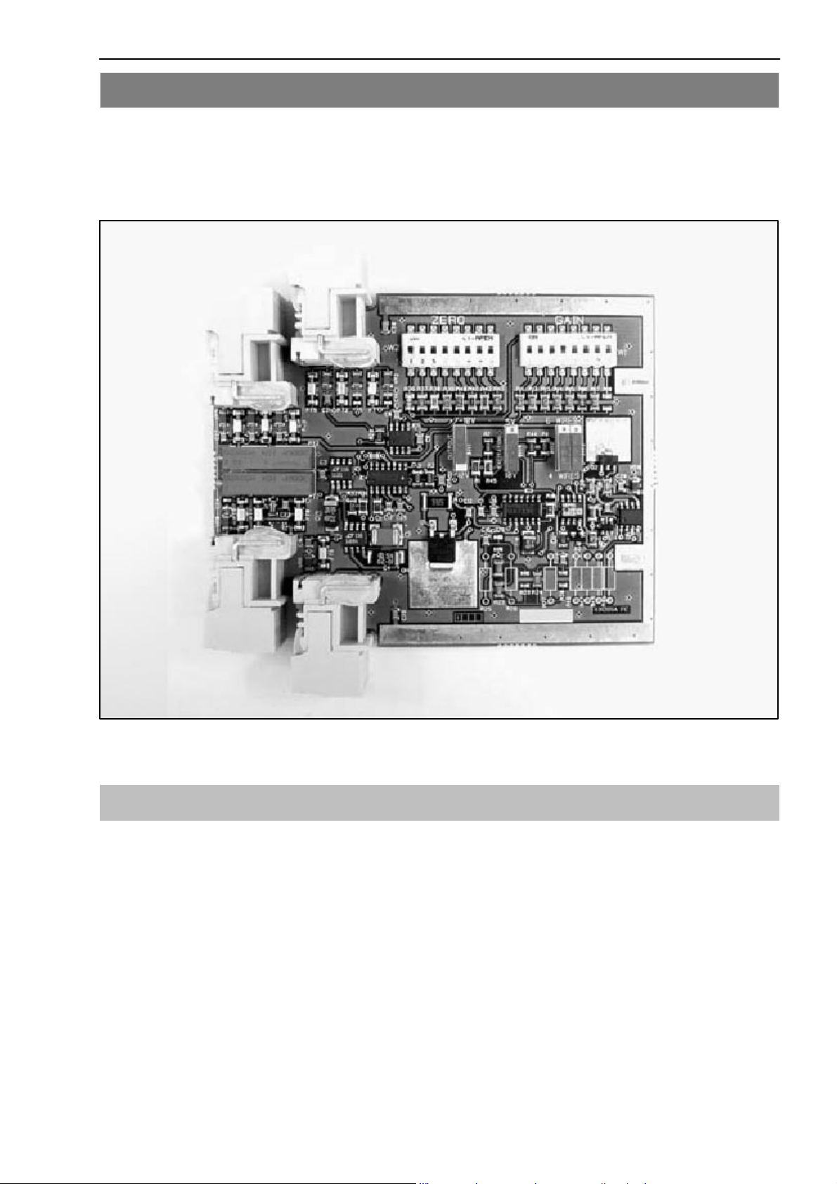
Bild 2: Bauteillageplan
4.1 Anschlussart
Der Aufnehmeranschluss sollte vorzugsweise in 6--Leitertechnik erfolgen. Die
Werkseinstellung ist in 4--Leitertechnik.
HBMA1091--21 de/en
Page 12

12
4.2 Schiebeschalterkonfigurierung
D INV1 stellt die Spannung/Strom Ausgänge ein:
0/10 V für 4/20 mA
10 V für 4/20 mA
D INV2 und INV 3 variieren die Schaltungsart:
4--Leiterschaltung
6--Leiterschaltung
D INV4 variiert die Brückenspeisung:
5VDC
10 V DC
4.3 Nullpunkteinstellung
Für einen präzisen Abgleich sollte das Gerät 15 Min. in Betrieb sein.
RM4220
Null wird mit W2 und PT2 eingestellt.
null (mV∕V) =
R
4 ⋅RW+R
Die Tabelle gilt für R
W2 R
1 3,9×10
2 2,2×10
3 750×10
4 301×10
5 121×10
6 49900 1,730 0,430
7 21000 4,000 1,000
8 9090 9,200 2,300
Brücke
⋅ 1000
Brücke
= 350 W /87W
Brücke
W2
W mV/V mV/V
6
6
3
3
3
Null für R
0,020 0,005
0,035 0,009
0,110 0,028
0,280 0,070
0,710 0,175
= 350 W Null für R
Brücke
Brücke
=87W
HBM A1091--21 de/en
Page 13
RM4220
4.4 Verstärkerkonfiguration
Der Endwert wird mit W1 und PT1 eingestellt.
Um eine möglichst hohe Auflösung des Messwertes zu erhalten, sollte die
max. Ausgangsspannung des Verstärkers ( 10V) ausgenutzt werden.
Tabelle für den Messbereich einstellbar mit W1.
W1 VE=5V VE=10V
mV/V mV/V
1 11,76 - - 25 5,88 -- 12,5
2 6,06 -- 12,9 3,03 -- 6,45
3 2,94 -- 6,25 1,47 -- 3,125
4 1,54 -- 3,28 0,77 -- 1,64
5 0,84 -- 1,74 0,42 -- 0,87
6 0,46 -- 0,96 0,23 -- 0,48
13
7 0,234 -- 0,5 0,117 -- 0,25
Messbereich in Abhängigkeit der Brückenspeisespannung VE.
Position 8 von W1 ist nicht benutzt.
Allgemein:
Teillast
Nennlast
Messbereich in V
⋅
10V
⋅ Kennwert in mV∕V = Nennmesswert (Range) in mV∕V
4.5 Filterkonfiguration
Die Filterbandbreite kann modifiziert werden mit R28, 29 und 30 in SMD--Bauform oder R25, 26 und 27 in konventioneller Technik.
R28, 29, 30 oder R25, 26, 27 Bandbreite
KW Hz
-- 3 (Werkseinstellung)
72,00 10
10,60 50
5,16 100
1,00 500
0,50 1000
0,10 5000
HBMA1091--21 de/en
Page 14

14
4.6 Werkseinstellung
INV1: 0/10V DC für 4/20mA
INV2 und INV3: 4--Leitertechnik
INV4: Speisespannung 10 V DC
W1: Position 1
W2: Position 1
3 Hz Bandbreite
5 Abmessungen
RM4220
Abmessungen in mm
99
114
HBM A1091--21 de/en
Page 15

RM4220
6 Anwendungen
6.1 Beispiel 1:
Wägezelle arbeitet mit Zug-- / Druckbelastung
Wägezelle
· Widerstand: 350 W
· Vollbrücke: 6--Leitertechnik
· Empfindlichkeit 3 mV/V
Konfiguration ( --3 mV/V für --10 V (4 mA) und 3 mV/V für 10 V (20 mA))
· Schalter INV1 einstellen auf 10V DC (4/20 mA)
· Schalter INV2 und INV3 einstellen auf 6--Leitertechnik
15
· Schalter INV4 einstellen auf die Speissespannung 10V DC
· Verstärkerschalter W1 auf Position 3
G =
Empfindlichkeit ⋅ Speisespannung
10
· Nullpunkteinstellung W2 auf Position 2 (Null = 0,035 mV/V)
· 3 Hz Bandbreite (Werkseinstellung)
Justierung
· Entlasten Sie den Aufnehmer.
· Justieren Sie PT2 auf 0 V (12 mA) mit einem Voltmeter (Amperemeter), falls
der Nullpunkt instabil ist, dann ersetzen Sie die Nullpunkteinstellung W2 auf
Position 3 und justieren nochmals PT2.
· Belasten Sie den Aufnehmer mit dem gewünschtem Endwert.
· Justieren Sie PT1 auf 10 V (20 mA) mit einem Voltmeter (Amperemeter)
· Überprüfen Sie die Nullpunktjustierung nochmals.
· Die Messkette ist nun justiert und betriebsbereit.
HBMA1091--21 de/en
Page 16

16
Anmerkung
Für 0/10 V (4/20 mA) Ausgang:
· Schalter INV1 umstellen auf Position 0/10 V (4/20 mA)
· Schalter INV2 und INV3 auf 6--Leitertechnik einstellen
· Schalter INV4 ist auf die Speisespannung 10 V DC einstellen
· Verstärkerschalter W1 auf Position 2
RM4220
G =
Empfindlichkeit ⋅ Speisespannung
5
· Nullpunkteinstellung W2 auf Position 7 (Null = 4,0 mV/V)
· Belasten Sie den Aufnehmer mit dem gewünschten Endwert und stellen da-
raufhin Spannungsendwert V
· Überprüfen Sie V
=5V(I
out
der Fall ist, justieren Sie PT1 so, dass gilt V
(Stromendwert Im)ein.
m
= 12 mA) für den Nullpunkt, falls dies nicht
out
out
=5V(I
=12mA).
out
· Entlasten Sie den Aufnehmer, justieren Sie PT2 auf 5 V (12 mA).
· Überprüfen Sie die Nullpunktjustierung nochmals.
· Die Messkette ist nun justiert und betriebsbereit.
6.2 Beispiel 2:
Wägezelle arbeitet mit Druckbelastung
Wägezelle
· Widerstand: 350 W
· Vollbrücke: 6--Leitertechnik
· Empfindlichkeit 3 mV/V
Konfiguration (0 mV/V für 0 V (4 mA) und 3 mV/V für 10 V (20 mA))
· Schalter INV1 einstellen auf 0/10 V DC (4/20 mA)
· Schalter INV2 und INV3 einstellen auf 6--Leitertechnik
· Schalter INV4 einstellen auf die Speissespannung 10 V DC
· Verstärkerschalter W1 auf Position 3
G =
Empfindlichkeit ⋅ Speisespannung
10
HBM A1091--21 de/en
Page 17

RM4220
17
· Nullpunkteinstellung W2 auf Position 2 (Null = 0,035 mV/V)
· 3 Hz Bandbreite (Werkseinstellung)
Justierung
· Entlasten Sie den Aufnehmer.
· Justieren Sie PT2 auf 0 V (4 mA) mit einem Voltmeter (Amperemeter), falls
der Nullpunkt instabil ist, dann ersetzen Sie die Nullpunkteinstellung W2 auf
Position 3 und justieren nochmals PT2.
· Belasten Sie den Aufnehmer mit dem gewünschtem Endwert.
· Justieren Sie PT1 auf 10 V (20 mA) mit einem Voltmeter (Amperemeter)
· Überprüfen Sie die Nullpunktjustierung nochmals.
· Die Messkette ist nun justiert und betriebsbereit.
Anmerkung
Für 10 V (4/20 mA) Ausgang:
· Schalter INV1 umstellen in Position 10 V (4/20 mA)
· Schalter INV2 und INV3 auf 6--Leitertechnik einstellen
· Schalter INV4 ist auf die Speisespannung 10 V DC einstellen
· Verstärkerschalter W1 auf Position 4
G =
Empfindlichkeit ⋅ Speisespannung
20
· Nullpunkteinstellung W2 auf Position 6 (Null = 1,730 mV/V)
· Belasten Sie den Aufnehmer mit dem gewünschten Endwert und stellen da-
raufhin Spannungsendwert V
· Überprüfen Sie V
=10V(I
out
ren sie PT1 so, dass gilt V
out
(Stromendwert Im)ein.
m
= 20 mA) falls dies nicht der Fall ist, justie-
out
=10V(I
=20mA).
out
· Entlasten Sie den Aufnehmer, justieren Sie PT2 auf 0 V (4 mA).
· Überprüfen Sie die Nullpunktjustierung nochmals.
· Die Messkette ist nun justiert und betriebsbereit.
HBMA1091--21 de/en
Page 18

18
7 Technische Daten
Typ RM4220
Genauigkeitsklasse 0,1
Nullabgleich
Maximum für Widerstand 87 W
Verstärkerjustierung
Maximum
Minimum
DMS--Vollbrücke
Brückenspeisespannung
DMS--Widerstand
Eingangsempfindlichkeit
Stromeingang
Eingangswiderstand
Stromausgang
Maximale Nichtlinearität
Ausgangswiderstand
Lastwiderstand
Ausgangsspannung
Ausgangskurzschlussstrom
Maximale Nichtlinearität
Filter (3. Ordnung)
Maximum
Minimum / Standard
Thermische Drift
Eingangsausgleichspannungsdrift
Thermische Kennwertdrift
Max. Stromaufnahme mA 200
Befestigung
Anschluss
Versorgungsspannung
Gebrauchstemperaturbereich
Lagerungstemperaturbereich
Temperaturstablisierungszeit
Entzündbarkeit
Schutzart IP20
Abmessungen
Gehäusematerial
Farbe
Gewicht g 130
mV/V
VDC
W
mV/V
nA
W typ
mA
%FSO
MW typ
W max.
V
mA
%FSO
Hz
Hz
V Ausgang
mV/°C Typ.
ppm/°C
VDC
°C
°C
min
mm 115 × 100 × 23
G = 1000 Þ 0,001
Tragschiene DIN EN50022
2,00
8500
80
5/10
80 min
0,3 ... 12
5
10
10
4/20
0,015
40
800
0/10 oder 10
22
5000 10 %
3 10 %
10
0,2/ 5G.
150
Schraubklemmen
24 8
0 ... + 70
-- 40 ... + 85
15
VO (UL94)
Polyamide PA
grau
RM4220
8 Reparatur
Bitte fügen Sie folgende Informationen bei Rücksendungen an HBM bei: HBM-Auftragsnummer, Grund der Rücksendung gegebenenfalls Ausfallursache.
HBM A1091--21 de/en
Page 19

RM4220
9 Konformitätserklärung
19
HBMA1091--21 de/en
Page 20

20
RM4220
HBM A1091--21 de/en
Page 21

RM4220
21
HBMA1091--21 de/en
Page 22

22
RM4220
HBM A1091--21 de/en
Page 23

Operating manual
S.G.--Amplifier
RM4220
A1091--21 de/en
Page 24

Page 25

RM4220
25
Content Page
Safety instructions 27..............................................
1 Application 30..................................................
2 Mounting / Dismounting 30......................................
3 Connection 31..................................................
4 Setup 33........................................................
4.1 Connection method 33........................................
4.2 Switch configurations 34......................................
4.3 Zero point configuration 34....................................
4.4 Amplifier configuration 35.....................................
4.5 Filter configuration 35.........................................
4.6 Factory setting 36............................................
5 Dimensions 36..................................................
6 Applications 37.................................................
6.1 Example 1: Load cell working with tension / compression 37.......
6.2 Example 1: Load cell working in compression 38.................
7 Technical data 40................................................
8 Service 40......................................................
9 Declaration of Conformity 41.....................................
HBMA1091--21 de/en
Page 26

26
RM4220
HBM A1091--21 de/en
Page 27

RM4220
27
Safety instructions
Appropriate use
The amplifier RM4220 with the connected transducer may be used for measurement and directly related control and regulation tasks, only. Any other use is
not appropriate.
To ensure safe operation, the module may only be used according to the specifications given in this manual. When using the transducer, the legal and safety regulations for t he respective application must also be observed. The
same applies if accessories are used.
The amplifier RM4220 has been designed for installation in closed metallic
housings (e.g. control cabinet)
General dangers in the case of non--observance of the safety instructions
The amplifier RM4220 complies with t he state of the art and is operationally
reliable. If the device is used and operated inappropriately by untrained personnel, residual dangers might develop.
Any person charged with device installation, operation, maintenance or repair
must in any case have read and understood the operating manual and the sa fety instructions, in particular.
Conditions on site
Protect the device from direct contact with water (IP20).
Maintenance and cleaning
The amplifier RM4220 are maintenance--free. Please note the following points
when cleaning the housing:
· Remove the mains plug from the sockets before cleaning.
· Clean the housing with soft, slightly damp (not wet!) cloth. Never use sol-
vents, since they may damage the labeling on the front panel.
· When cleaning, please ensure that no liquid finds ist way into the device or
onto the contacts.
HBMA1091--21 de/en
Page 28

28
Residual dangers
The amplifier RM4220 scope of performance and supply covers part of the
measuring--technology, only. The plant designer/ constructor/ operator must in
addition design, realize and take responsibility for the measuring-- system’s safety such that potential residual dangers are minimized. The respective regulations must in any case be observed. Residual dangers regarding the
measuring system must be specified explicitly.
If there is any risk of remaining dangers when working with t he, it is pointed
out in this introduction by means of the following symbols:
RM4220
Symbol:
Meaning: Maximum danger level
Warnsofanimminently dangerous situation in which failure to comply with
safety requirements will result in death or serious physical injury.
Symbol:
Meaning: Dangerous situation
Warnsofapotentially dangerous situation in which failure to comply with safety requirements can result in death or serious physical injury.
Symbol:
Meaning: Potentially dangerous situation
DANGER
WARNING
CAUTION
Warnsofapotentially dangerous situation in which failure to comply with safety requirements could result in damage to property or some form of physical injury.
Symbol:
Means that important information about the product or ist handling is being gi-
ven.
HBM A1091--21 de/en
NOTE
Page 29

RM4220
29
Symbol:
Meaning: CE mark
The CE mark enables the manufacturer to guarantee that the product complies with the requirements of the relevant EC directives (see Declaration of
Conformity at the end of this document)
Reconstruction and modifications
HBM’s express consent is required for modifications regarding the amplifier
RM4220 construction and safety. HBM does not take responsibility f or damage resulting from unauthorized modifications.
In particular, repair and soldering works on the boards are prohibited. If complete componentry is replaced use original HBM components, only.
Qualified personnel
The device may be used by qualified personnel, only; the technical data and
the special safety regulations must in any case be observed. When using the
device, the legal and safety regulations for the respective application must
also be observed. The same applies if accessories are used.
Qualified personnel means: personnel familiar with the installation, mounting,
start--up and operation of the product, and trained according to their job.
Maintenance and repair work on an open device with the power on should
only be undertaken by trained personnel who are aware of the above--mentioned dangers.
HBMA1091--21 de/en
Page 30

30
RM4220
1 Application
The module RM4220 is a strain gauge amplifier. This amplifier offers a very
simple and practical calibration of the zero point and the final value by using
DIP-- switches and potentiometer. The excitation voltage is selectable with 5
or 10 V. The output signal is 0/10 V or 10V and 4/20 mA.
The connection of the transducer is either possible in 4-- or 6--wire technique.
If you use the 6--wire technique, you can neglect the effects on resistance variation of the extension wire. The housing made of polyamide PA typ PHOENIX EM can be hooked up with every DIN EN support rail. (EN 50022 standard)
Voltage Reference 5/10 V
Zero
Gain
Amplifier + Filter Output Interface
Power Supply
24 V →15 V
Power Supply
24 V
0/10 V Output or
10 V Output
4/20VmAOutput
Fig. 1: Illustration of principle
2 Mounting / Dismounting
The housing is installed onto mounting rails to DIN EN 50022; they are hooked onto the upper edge and snapped into the spring plate on the lower edge.
For dismounting, use a screwdriver to push down the spring plate and unhook
he housing.
HBM A1091--21 de/en
Page 31

RM4220
31
3 Connection
The connection of the amplifier and the connection of the voltage supply take
place by four peelable connectors. Individual wires can be clamped in a range
of 0,13 mm
should be used to connect the cores to the terminals. Cores with or without
end sleeves must not be tin--plated.
The 4 connectors are labeled with numbers, so they can inserted in the 4 sokkets with no danger of a mix--up.
The subsequent figures give the respective connection diagrams that are printed onto the housing cover.
For 4--wire technique (factory setting)
2
... 1,5 mm2.End sleeves (without plastics hoop, length 10 mm)
Typ RM4220
Terminal Function Color (HBM -- cable
4--wire technique)
1 Measuring signal (-) RD (red)
2 Screen
3
4 Bridge excitation voltage (+) BU (blue)
5 Measuring signal (+) WH (white)
6
7
8 Bridge excitation voltage (--) BK (black)
9 Supply voltage (V+)
10
11 Output voltage
12 GND = Ground
13 GND = Ground
14
15 Current output
16 Ground
HBMA1091--21 de/en
Page 32

32
For 6--wire technique
Typ RM4220
Terminal Function Color (HBM -- cable
1 Measuring signal (-) RD (red)
2 Screen
3 Sensor line (+) GN (green)
4 Bridge excitation voltage (+) BU (blue)
5 Measuring signal (+) WH (white)
6
7 Sensor line (--) GY (gray)
8 Bridge excitation voltage (--) BK (black)
9 Supply voltage (V+)
10
11 Output voltage
12 GND = Ground
RM4220
6--wire technique)
13 GND = Ground
14
15 Current output
16 Ground
HBM A1091--21 de/en
Page 33

RM4220
4Setup
If all cables are connected, proceed as follows:
· Connect transducer cable
· Switch on supply voltage
33
Fig. 2: Component layout
4.1 Connection method
The transducer connection--method should preferably take place in 6--wire
technique. The factory setting is 4--wire technique.
HBMA1091--21 de/en
Page 34

34
RM4220
4.2 Switch configurations
D INV1 positions the voltage/ current output:
0/10 V for 4/20 mA
10 V for 4/20 mA
D INV2 and INV3 vary the switching mechanism:
4 wire circuit
6 wire circuit
D INV4 varies the excitation voltage:
5VDC
10 V DC
4.3 Zero point configuration
For an high precision adjustment electronic needed 15 min in process.
Zero is adjustable with W2 and PT2.
R
zero (mV∕V) =
4 ⋅RW+R
This table applies for R
W2 R
1 3,9×10
2 2,2×10
3 750×10
4 301×10
5 121×10
6 49900 1.730 0.430
7 21000 4.000 1.000
8 9090 9.200 2.300
bridge
⋅ 1000
bridge
bridge
= 350 Ω /87Ω
W2
W mV/V mV/V
6
6
3
3
3
Zero for R
0.020 0.005
0.035 0.009
0.110 0.028
0.280 0.070
0.710 0.175
= 350 W Zero for R
bridge
bridge
=87W
HBM A1091--21 de/en
Page 35

RM4220
4.4 Amplifier configuration
The ultimate value is adjustable with W1 and PT1.
To obtain the maximum measurement resolution, the max. amplifier output--
voltage ( 10 V) should be used.
Table for the measuring range adjustable with W1.
W1 VE=5V VE=10V
mV/V mV/V
1 11.76 -- 25 5.88 -- 12.5
2 6.06 -- 12.9 3.03 -- 6.45
3 2.94 -- 6.25 1.47 -- 3.125
4 1.54 -- 3.28 0.77 -- 1.64
5 0.84 -- 1.74 0.42 -- 0.87
6 0.46 -- 0.96 0.23 -- 0.48
7 0.234 -- 0.5 0.117 -- 0.25
35
Measuring range according to exitation voltage VE.
Position 8 of W1 can not be used.
Formula:
Part load
Nom. load
Measuring range in V
⋅
10V
⋅ Sensitivity in mV∕V = Nom. measuring value (Range) in mV∕V
4.5 Filter configuration
The filter bandwidth can be modified with R28, 29 and 30 in SMD--model or
R25, 26 and 27 in conventionally technique.
R28, 29, 30 or R25, 26, 27 Bandwidth
KW Hz
-- 3 (factory setting)
72.00 10
10.60 50
5.16 100
1.00 500
0.50 1000
0.10 5000
HBMA1091--21 de/en
Page 36

36
4.6 Factory setting
INV1: 0/10 V DC for 4/20 mA
INV2 und INV3: 4--wire technique
INV4: excitation voltage 10 V DC
W1: position 1
W2: position 1
3 Hz Bandwidth
5 Dimensions
RM4220
Dimensions in mm
99
114
HBM A1091--21 de/en
Page 37

RM4220
6 Applications
6.1 Example 1:
Load cell working with tension / compression
Loadcell
· Resistance: 350 W
· Full bridge: 6--wire technique
· Sensitivity: 3 mV/V
Configuration (--3 mV/V for --10 V (4 mA) und 3 mV/V for 10 V (20 mA))
· Switch INV1 synchronize to 10 V DC (4/20 mA)
· Switch INV2 und INV3 synchronize to 6--wire technique
37
· Switch INV4 synchronize to excitation voltage 10 V DC
· Amplifier switch W1 onto position 3
G =
· Zero point configuration W2 onto position 2 (Zero = 0.035 mV/V)
· 3 Hz Bandwidth (factory setting)
Adjustment
· Release the transducer.
· Adjust PT2 to 0 V (12 mA) with a voltmeter (ammeter). If the zero point is
unstable, then replace the zero point configuration W2 onto position 3 and
adjust PT2 again.
· Load the transducer with the favored final value.
· AdjustPT1to10V(20mA)withavoltmeter(ammeter).
sensitivity ⋅ excitation voltage
10
· Verify the zero point configuration once again.
· The measurement chain is now adjusted and ready for operation.
HBMA1091--21 de/en
Page 38

38
Remark
For 0/10 V (4/20 mA) output:
· Switch INV1 synchronize to position 0/10 V (4/20 mA)
· Switch INV2 and INV3 synchronize to 6--wire technique
· Switch INV4 synchronize to the excitation voltage 10 V DC
· Amplifier switch W1 onto position 2
RM4220
G =
sensitivity ⋅ excitation voltage
5
· Zero point configuration W2 onto position 7 (zero = 4.0 mV/V)
· Load the transducer with the favoured final value and adjust thereupon vol -
tage final value V
· Verify V
=5V(I
out
just PT1 in t he way, that it applies V
(current final value Im).
m
12 mA) for the zero point, if this is not the case, ad-
out =
out
=5V(I
out =
12 mA).
· Release the transducer, adjust PT2 to 5 V (12 mA).
· Verify the zero point configuration once again.
· The measurement chain is now adjusted and ready for operation.
6.2 Example 1:
Load cell working in compression
Loadcell
· Resistance: 350 W
· Full bridge: 6--wire technique
· Sensitivity: 3 mV/V
Configuration (0 mV/V for 0 V (4 mA) und 3 mV/V for 10 V (20 mA))
· Switch INV1 synchronize to 0/10 V DC (4/20 mA)
· Switch INV2 und INV3 synchronize to 6--wire technique
· Switch INV4 synchronize to excitation voltage 10 V DC
· Amplifier switch W1 onto position 3
G =
sensitivity ⋅ excitation voltage
10
HBM A1091--21 de/en
Page 39

RM4220
· Zero point configuration W2 onto position 2 (Zero = 0.035 mV/V)
· 3 Hz Bandwidth (factory setting)
Adjustment
· Release the transducer.
· Adjust PT2 to 0 V (4 mA) with a voltmeter (ammeter). If the zero point is
unstable, then replace the zero point configuration W2 onto position 3 and
adjust PT2 again.
· Load the transducer with the favored final value.
· AdjustPT1to10V(20mA)withavoltmeter(ammeter).
· Verify the zero point configuration once again.
· The measurement chain is now adjusted and ready for operation.
39
Remark
For 10 V (4/20 mA) output:
· Switch INV1 synchronize to position 10 V (4/20 mA)
· Switch INV2 and INV3 synchronize to 6--wire technique
· Switch INV4 synchronize to the excitation voltage 10 V DC
· Amplifier switch W1 onto position 4
G =
sensitivity ⋅ excitation voltage
20
· Zero point configuration W2 onto position 6 (zero = 1.730 mV/V)
· Load the transducer with the favoured final value and adjust thereupon vol -
tage final value V
· Verify V
= 10V (I
out
just PT1 in t he way, that it applies V
(current final value Im).
m
20 mA) for the zero point, if this is not the case, ad-
out =
out
=10V(I
out =
20 mA).
· Release the transducer, adjust PT2 to 0 V (4 mA).
· Verify the zero point configuration once again.
· The measurement chain is now adjusted and ready for operation.
HBMA1091--21 de/en
Page 40

40
7 Technical data
Typ RM4220
Accuracy class 0.1
Zero adjustment
Maximum for impedance 87 W
Amplifier gain
Maximum
Minimum
Strain gages
Excitation voltage
S.G. impedance
S.G. sensitivity
Input current
Input impedance
mV/V
VDC
W
mV/V
nA
W typ
2.00
8500
80
5/10
80 min
0,3 ... 12
5
10
10
RM4220
Output current
Maximum non--linearity
Output impedance
Load resistance
Output voltage
Output short--circuit current
Max. non--linearity
Filter (3rd order)
Maximum
Minimum / standard
Thermal drift
Input offset voltage drift
Thermal sensitivity drift
Max. current consumption mA 200
Fixture
Connection
Power supply
Operating temperature
Storage temperature
Temperature stabilization time
Inflammability
Degree of protection IP20
mA
%FSO
MW typ
W max.
V
mA
%FSO
Hz
Hz
V Output
mV/°C Typ.
ppm/°C
VDC
°C
°C
min
4/20
0,015
40
800
0/10 or 10
22
G = 1000 Þ 0,001
5000 10 %
3 10 %
10
0.2/ 5G.
150
Mounting rail DIN EN50022
Screw terminal
24 8
0 ... + 70
-- 40 ... + 85
15
VO (UL94)
Dimensions
Housing material
Color
Weight g 130
mm 115 × 100 × 23
Polyamide PA
grey
8 Service
Please enclose following information when returning to HBM: HBM--order
number, reason for t he return if necessary cause of failure.
HBM A1091--21 de/en
Page 41

RM4220
9 Declaration of Conformity
41
HBMA1091--21 de/en
Page 42

42
RM4220
HBM A1091--21 de/en
Page 43

RM4220
43
HBMA1091--21 de/en
Page 44

p
p
A
1091--21 de/en
Änderungen vorbehalten.
Alle Angaben beschreiben unsere Produkte in allgemeiner Form.
Sie stellen keine Eigenschaftszusicherung im Sinne des §459,
Abs. 2, BGB dar und begründen keine Haftung.
Modifications reserved.
All details describe our products in general form only.They are
not to be understood as express warranty and do not constitute
any liability whatsoever.
Hottinger Baldwin Messtechnik GmbH
Postfach 10 01 51, D-64201 Darmstadt
Im Tiefen See 45, D-64293 Darmstadt
Tel.: +49/61 51/ 8 03-0; Fax: +49/61 51/ 8039100
E--mail: su
ort@hbm.com www.hbm.com
 Loading...