

Page 1
Operating Manual
English
PMX
Page 2

Hottinger Baldwin Messtechnik GmbH
Im Tiefen See 45
D-64239 Darmstadt
Tel. +49 6151 803-0
Fax +49 6151 803-9100
info@hbm.com
www.hbm.com
Mat.: 7-2002.4354
DVS: A4354-2.2 HBM: public
11.2016
E Hottinger Baldwin Messtechnik GmbH.
Subject to modifications.
All product descriptions are for general information only.
They are not to be understood as a guarantee of quality or
durability.
Page 3

English
1 Safety instructions 13.......................................
2 Symbols on the device 20...................................
3 User information 21.........................................
3.1 Using this manual 21.........................................
3.2 About the PMX documentation 22..............................
3.3 Symbols used in this manual 23...............................
4 PMX product description 24.................................
5 Model overview, scope of supply, accessories 29.............
5.1 The PMX system 29.........................................
5.2 Scope of delivery 34.........................................
5.3 Accessories 34..............................................
5.4 PMX web server/software 36..................................
6 Degree of protection / housing / shielding design 41..........
7 Mounting/Dismounting/Replacing 43........................
7.1 Mounting tools and tightening torques 43.......................
7.2 Support rail mounting 44......................................
7.3 Wall-mounting 48............................................
7.4 Replacing measurement and communication cards 50............
8 Electrical connections PMX 53..............................
8.1 Plug technology and clamping areas 53.........................
8.2 Overview of PMX functions 54.................................
8.2.1 Combination options 55.......................................
8.2.2 Relevance of the basic device connection sockets 55.............
8.2.3 LEDs for system monitoring (device LED) 57....................
8.2.4 Fieldbus LED 58.............................................
8.2.5 Measurement card LEDs 65...................................
PMX A4354-2.2 HBM: public 3
Page 4

8.3 Supply voltage 69............................................
8.4 Measurement cards / transducer connection 70..................
8.4.1 Intrinsically safe measurement circuits - Operation with
Zener barriers 70............................................
8.4.2 PX455 71...................................................
8.4.2.1 Strain gage and inductive full and half bridges
(6-wire configuration) 72......................................
8.4.2.2 Strain gage and inductive full and half bridges
(4-wire configuration) 73......................................
8.4.2.3 LVDT 74...................................................
8.4.2.4 Potentiometric transducer 75..................................
8.4.2.5 PX455 with Pt100 temperature measurement 76.................
8.4.3 PX401 78...................................................
8.4.3.1 Voltage source ± 10 V 79.....................................
8.4.3.2 Current source ± 20 mA 80...................................
8.4.3.3 Current source ± 20 mA 81...................................
8.4.3.4 IEPE transducers with external measuring amplifier 82...........
8.4.3.5 PX401 with charge amplifier 83................................
8.4.4 PX460 87...................................................
8.4.4.1 Voltage supply for signal transmitter and transducer up to
24 VDC nominal (rated) voltage. 89............................
8.4.4.2 Voltage supply for signal transmitter and transducer up to
5 VDC nominal (rated) voltage 90..............................
8.4.4.3 Frequency measurement symmetrical (differential) 91............
8.4.4.4 Frequency measurement symmetrical (single-pole) 92............
8.4.4.5 Encoder and incremental encoder, symmetrical (differential) 93....
8.4.4.6 Encoder and incremental encoder, asymmetrical (single-pole) 94...
8.4.4.7 SSI encoder (active only) 95..................................
8.4.4.8 Inductive encoder or pulse encoder (passive only) 96.............
8.4.4.9 Connection and configuration of the HBM torque flange
(T10, T12, T40) 98...........................................
4 A4354-2.2 HBM: public PMX
Page 5

8.4.4.10 Connection and configuration of the HBM torque transducer
T20WN (without VK20A) 105...................................
8.4.4.11 Connection and configuration of the HBM torque transducer
T20WN (with VK20A) 107......................................
8.5 Input/output cards 108.........................................
8.5.1 PX878 108...................................................
8.5.1.1 Analog output ± 10 V 109.....................................
8.5.1.2 Digital inputs / digital outputs 110...............................
8.5.2 External supply voltage for digital inputs and outputs (PX878) 112...
8.6 Communication cards 115.....................................
8.6.1 Pin assignment PX01EC EtherCAT® fieldbus module 115..........
8.6.2 Pin assignment PX01EP EtherNet/IP fieldbus module 115..........
8.6.3 Pin assignment PX01PN PROFINET-IO fieldbus module 116.......
8.7 TEDS transducer 116.........................................
8.7.1 TEDS connection 116.........................................
8.7.2 Starting up the TEDS module 118...............................
8.7.3 PMX parameterization with TEDS 118...........................
9 Synchronization and Time recording 120......................
9.1 Synchronizing via internal PMX synchronization 121...............
9.2 External synchronous measurement acquisition via an NTP
server in the network 124......................................
9.3 Measurement acquisition via EtherCAT fieldbus, ProfiNET,
Ethernet/IP 125...............................................
9.4 Comparison of synchronization mechanisms 126..................
10 Network, data security, policies, passwords 127...............
10.1 Network access and remote maintenance 127....................
10.2 Data security 129.............................................
10.3 Policies definition and passwords 129...........................
10.3.1 Policies definition 129.........................................
10.3.2 Passwords 130...............................................
PMX A4354-2.2 HBM: public 5
Page 6

11 Startup 131..................................................
11.1 Hardware setup 131...........................................
11.1.1 Voltage supply / transducers 131...............................
11.1.2 Ethernet connection 131.......................................
11.2 Integrated PMX web server 132................................
11.2.1 System requirements 132......................................
11.3 Connect the PMX with a PC (HOST) or via a network 132..........
11.3.1 Restoring lost network settings 139.............................
11.4 Display and control options 142.................................
11.5 Menu structure PMX web server 146............................
11.5.1 Overview -> SETTINGS 146...................................
11.5.2 Factory settings 147..........................................
11.6 PMX startup behavior 148.....................................
11.7 PMX operating behavior 149...................................
11.8 Signal runtimes 151...........................................
11.9 Fieldbus integration 156.......................................
11.9.1 PROFINET connection 156....................................
11.9.2 EtherCAT® connection 157....................................
11.9.3 Adjusting the fieldbus update rate 159...........................
11.9.4 EtherNet/IP connection 159....................................
12 Quick start 161..............................................
12.1 Preparing the measurement system 161.........................
12.2 Typical operating procedure 167................................
12.2.1 Measurement example 167....................................
12.4 Update software (PMX web server) 174..........................
13 Internal calculation channels 175.............................
13.1 Calculation rate 176...........................................
13.2 Description of calculations 177..................................
13.2.1 Scaling 177..................................................
13.2.1.1 Two-point scaling 177.........................................
6 A4354-2.2 HBM: public PMX
Page 7

13.2.1.2 Characteristic curve table (21 interpolation points) 177.............
13.2.1.3 Polynomial 4th order 178......................................
13.2.1.4 Taring 179...................................................
13.2.1.5 6x6 Matrix 181...............................................
13.2.1.6 SG stress analysis 182........................................
13.2.2 Evaluation functions 184.......................................
13.2.2.1 Filter (high pass, low pass, CAMSA) 184.........................
13.2.2.2 Angular synchronous filter 186..................................
13.2.2.3 Extreme Value (Peak) 188.....................................
13.2.2.4 Tolerance window 190.........................................
13.2.2.5 Hold function (analog) 194.....................................
13.2.2.6 Hold (digital) 195.............................................
13.2.2.7 Mean values (arithmetic, RMS) 196.............................
13.2.2.8 Moving Average 198..........................................
13.2.2.9 Trigger function (range) 199....................................
13.2.2.10Trigger function (pulse) 201....................................
13.2.3 Mathematical functions 204....................................
13.2.3.1 Adder 204...................................................
13.2.3.2 Multiplier 204.................................................
13.2.3.3 Divider 205..................................................
13.2.3.4 Counter 205..................................................
13.2.3.5 Integrator 206................................................
13.2.3.6 Differentiator 207.............................................
13.2.3.7 Cartesian to polar coordinates 208..............................
13.2.3.8 Polar coordinates to Cartesian coordinates 208...................
13.2.3.9 Modulo function 209...........................................
13.2.3.10Constant signal 209...........................................
13.2.4 Technology functions 210......................................
13.2.4.1 2-state controller 210..........................................
13.2.4.2 PID controller 211.............................................
13.2.4.3 RTD PT100 at PX455 213.....................................
13.2.4.4 Signal generators (rectangle, triangle, sine) 215...................
PMX A4354-2.2 HBM: public 7
Page 8

13.2.4.5 Logic modules (AND, OR…) 216................................
13.2.4.6 Multiplexer 4:1 217............................................
13.2.4.7 Dead time 217................................................
13.2.4.8 Edge detector 218............................................
13.2.4.9 Pulse width measurement 219..................................
13.2.4.10 Timer 222...................................................
13.2.4.11 Connection with (optional) delay (CODESYS) 223.................
13.3 Example calculations 223......................................
13.3.1 Generation of peak values 223.................................
13.3.2 Calculating the force introduction point 225.......................
13.3.3 Mechanical work via force/displacement integration 233............
13.3.4 Testing force at specific points on the displacement axis 242.......
13.3.5 Force/displacement measurement with relative zero point 248......
13.3.6 Checking force against a tolerance band 254.....................
13.3.7 Event counter 261............................................
14 Test signals and signal generators 265........................
15 Parameter sets (measurement programs) 267..................
15.1 Setting parameter sets 269.....................................
15.2 Changing from parameters to parameter sets 271.................
16 Communication with a control system 276....................
16.1 Device description file 276.....................................
16.2 Setting the transmission speed of the fieldbus 281................
16.3 Data transmission by fieldbus 281...............................
16.4 Input data, PMX aController (PLC) 282.........................
16.4.1 Device data (cyclic) 282.......................................
16.4.2 System status 283............................................
16.4.3 Measured values (cyclic) 284...................................
16.4.4 Measured value status 286.....................................
16.5 Output data, controller (PLC) a PMX 287........................
16.5.1 Device data (cyclic) 287.......................................
8 A4354-2.2 HBM: public PMX
Page 9

16.5.2 Measured value control words (cyclic) 289.......................
16.5.3 Measured value control words 291..............................
16.5.4 Fieldbus channels 292.........................................
16.6 PROFINET 294..............................................
16.7 EtherCAT 296..............................................
16.8 Using the PMX CoE Object Dictionary 298.......................
16.9 EtherNet/IP 301..............................................
16.9.1 Configuration 301.............................................
16.9.2 Channel settings 303..........................................
16.9.3 Data structure 304............................................
17 CAN interface (WGX001 only) 314.............................
17.1 General 314..................................................
17.2 CAN pin assignment 314......................................
17.3 CANopen master / slave operation 316..........................
18 CODESYS‐V3 Soft PLC (WGX001 only) 318....................
18.1 General 318..................................................
18.3 Preparation 321..............................................
18.4 Create project 322............................................
18.5 Add PMX library 323..........................................
18.6 PMX library 324..............................................
18.7 Task configuration 347........................................
18.8 Cyclic data 348...............................................
18.9 Signal run diagram (I/O‐Mapping) 349...........................
18.10 System events for PMX 351....................................
18.10.1 All 351......................................................
18.10.2 com.hbm.fwconfig 352.........................................
18.10.3 com.hbm.parameter 353.......................................
18.10.4 com.hbm.fpgasrv 355.........................................
18.10.5 com.hbm.SysCfgMgr 356......................................
18.10.6 com.hbm.storagemanager 363.................................
PMX A4354-2.2 HBM: public 9
Page 10

18.10.7 com.hbm.sigproc 364.........................................
18.10.8 com.hbm.fieldbus 365.........................................
18.10.9 com.hbm.CatmanServer 365...................................
18.10.10 com.hbm.meassrv 366........................................
18.10.11 com.hbm.httpdata 366.........................................
18.10.12 GUI 366.....................................................
18.11 WebVisualisation 370.........................................
18.12 CAN interface 371............................................
18.13 CAN‐Master and Slave mode 372...............................
18.14 PMX package 391............................................
19 Data storage 393.............................................
20 Data acquisition software (DAQ) catmanEASY/AP 395..........
21 PMX command set (API) 397..................................
21.1 Requirements 397............................................
21.1.1 Example: TELNET connection 398..............................
21.2 Command list 400............................................
21.3 Examples 482................................................
22 Object directory 487.........................................
22.1 Accessible Data Objects 487...................................
22.1.1 Measuring channels 488.......................................
22.1.2 Calculated Channels 490......................................
22.2 The Numbering Scheme 490...................................
22.2.1 General Objects 491..........................................
22.2.2 Measuring channels 492.......................................
22.2.3 Calculated Channels 492......................................
22.2.4 The Constant Signals 493......................................
22.2.5 Passwords 493...............................................
22.3 Data Types 494..............................................
22.4 Access via Ethernet Command Interface 495.....................
10 A4354-2.2 HBM: public PMX
Page 11

22.5 Access via Field Bus 497......................................
22.5.1 Submitting a Request 499......................................
22.5.2 Bit Allocation 500.............................................
22.5.3 The Reply from PMX 501......................................
22.5.3.1 Reply to a Read Request 502..................................
22.5.3.2 Reply to a Write Request 502..................................
22.5.3.3 Retry 502....................................................
22.6 Make the New Value Effective 503..............................
22.7 Generated Header Files 503...................................
22.7.1 Value Ranges of the Objects 505...............................
22.8 Hints zur Nutzung des Objektverzeichnisses 506..................
23 Firmware update 507.........................................
23.1 Preparation 507..............................................
23.2 Install firmware 508...........................................
24 Diagnosis and maintenance 510..............................
24.1 Error messages / Operating state (LED display) 510...............
24.2 Error messages of the device status 516.........................
24.2.1 Error in factory settings 517....................................
24.2.2 SYNC Master 517............................................
24.2.3 SYNC error 517..............................................
24.2.4 SYNC controller error 517......................................
24.2.5 Heartbeat 517................................................
24.2.6 Sensor supply overloaded 517..................................
24.2.7 Buffer overflow in command interface 518........................
24.2.8 System not ready 518.........................................
24.2.9 CPU overload during calculations 518...........................
24.3 Resetting the PMX administrator password 519...................
24.4 Resetting the PMX to factory settings 520........................
24.5 Restoring lost PMX network settings and device names 521........
24.7 Replacing measurement and communication cards 526............
PMX A4354-2.2 HBM: public 11
Page 12

24.8 Log file 527..................................................
24.8.1 System log entries for system status 528........................
24.8.2 System log entries for channel status / measured value status 529..
25 Quality certification and calibration certificates 531............
26 FAQs 532...................................................
27 Technical support 537.......................................
28 Waste disposal and environmental protection 539.............
29 Glossary 541................................................
30 Index 549...................................................
12 A4354-2.2 HBM: public PMX
Page 13

1 Safety instructions
Appropriate use
The PMX amplifier system is to be used exclusively for
measurement tasks and directly related control tasks.
Use for any purpose other than the above is deemed to
be non-designated use. In the interests of safety, the
device should only be operated as described in the
Operating Manuals. It is also essential to comply with the
legal and safety requirements for the application
concerned during use. The same applies to the use of
accessories.
Each time, before starting up the equipment, you must
first run a project planning and risk analysis that takes
into account all the safety aspects of automation
technology. This particularly concerns personal and
machine protection.
Additional safety precautions must be taken in plants
where malfunctions could cause major damage, loss of
data or even personal injury. In the event of a fault, these
precautions establish safe operating conditions.
Safety instructions
This can be done, for example, by mechanical
interlocking, error signaling, limit value switches, etc.
Notice
The device must not be directly connected to the DC
voltage supply system. Supply voltage 10 V … 30 V
(DC).
Before commissioning, ensure that a suitable supply
voltage is used and that the circuit used is sufficiently
protected.
PMX A4354-2.2 HBM: public 13
Page 14

Safety instructions
The device may only be supplied with separated extralow voltage (safety isolating transformer according to DIN
VDE 0551 / EN60742). Only operate built-in devices once
they are installed in the housing provided. The device
development is based on DIN EN 61010 Part 1 (VDE
0411 Part 1).
General dangers of failing to follow the safety
instructions
The PMX system is a state of the art unit and as such is
reliable. The module may give rise to dangers if it is
inappropriately installed and operated by untrained
personnel.
Any person instructed to carry out installation, starting up,
maintenance or repair of the module must have read and
understood the Operating Manual and in particular the
technical safety instructions.
Conditions at the place of installation
S Protect the device from direct contact with water.
S Protect the PMX system from moisture and humidity
or weather conditions such as rain, snow, etc.
S Do not expose the device to direct sunlight.
S Please observe the permissible maximum ambient
temperatures stated in the specifications.
S The permissible relative humidity at 31 °C is 95 %
(non condensing); linear reduction to 50 % at 40 °C.
S Install the device so that it can be disconnected from
the supply voltage at any time without difficulty.
S It is safe to operate the PMX system up to a height of
2000 m.
14 A4354-2.2 HBM: public PMX
Page 15

Safety instructions
Maintenance and cleaning
The PMX system is maintenance-free.
S Before cleaning, disconnect all connections.
S Clean the housing with a soft, slightly damp (not wet!)
cloth. You should never use solvents, since these
could damage the labeling.
S When cleaning, ensure that no liquid gets into the
module or connections.
Residual dangers
The scope of supply and performance of the PMX system
only covers a small area of measurement technology. In
addition, equipment planners, installers and operators
should plan, implement and respond to the safety
engineering considerations of measurement technology
in such a way as to minimize remaining dangers. On-site
regulations must be complied with at all times. There
must be reference to the remaining dangers connected
with measurement technology.
Product liability
In the following cases, the protection provided for the
device may be adversely affected. Liability for device
functionality then passes to the operator:
S The device is not used in accordance with the
operating manual.
S The device is used outside the field of application
described in this Chapter.
S The operator makes unauthorized changes to the
device.
PMX A4354-2.2 HBM: public 15
Page 16

Safety instructions
Warning signs and danger symbols
Important instructions for your safety are specifically
identified. It is essential to follow these instructions in
order to prevent accidents and damage to property.
Safety instructions are structured as follows:
WARNING
Type of danger
Consequences of non-compliance
Averting the danger
S Warning sign:
draws your attention to the danger
S Signal word:
indicates the severity of the danger (see table below)
S Type of danger:
mentions the type or source of the danger
S Consequences:
describes the consequences of non-compliance
S Defense:
indicates how the danger can be avoided/bypassed
16 A4354-2.2 HBM: public PMX
Page 17

Danger class according to ANSI
Symbol Significance
WARNING
CAUTION
Notice
This marking warns of a potentially dangerous
situation in which failure to comply with safety
requirements can result in death or serious physical
injury.
This marking warns of a potentially dangerous
situation in which failure to comply with safety
requirements can result in slight or moderate physical
injury.
This marking draws your attention to a situation in
which failure to comply with safety requirements can
lead to damage to property.
Working safely
Notice
The device must not be directly connected to the DC
voltage supply system. Supply voltage 10 V … 30 V
(DC).
Safety instructions
The supply connection, as well as the signal and sense
leads, must be installed in such a way that
electromagnetic interference does not adversely affect
module functionality (HBM recommendation: "Greenline
shielding design", downloadable from the Internet at
http://www.hbm.com/Greenline
).
Automation equipment and devices must be installed in
such a way that adequate protection or locking against
unintentional actuation is provided (e.g. access checks,
password protection, etc.).
When devices are working in a network, these networks
must be designed in such a way that malfunctions in
individual nodes can be detected and shut down.
PMX A4354-2.2 HBM: public 17
Page 18

Safety instructions
Safety precautions must be taken both in terms of
hardware and software, so that a line break or other
interruptions to signal transmission, such as via the bus
interfaces, do not cause undefined states or loss of data
in the automation device.
Conversions and modifications
The device must not be modified from the design or
safety engineering point of view except with our express
agreement. Any modification shall exclude all liability on
our part for any damage resulting therefrom.
In particular, any repair or soldering work on
motherboards is prohibited. When exchanging complete
modules, use only original parts from HBM. The product
is delivered from the factory with a fixed hardware and
software configuration. Changes can only be made within
the possibilities documented in the operating manual.
Qualified personnel
Qualified personnel means persons entrusted with siting,
mounting, starting up and operating the product, who
possess the appropriate qualifications for their function
(qualified electrician, or by someone with electrical
training under the supervision of a qualified electrician).
This device is only to be installed and used by qualified
personnel strictly in accordance with the specifications
and with the safety rules and regulations which follow.
This includes people who meet at least one of the three
following requirements:
S Knowledge of the safety concepts of automation
technology is a requirement and, as project personnel,
you must be familiar with these concepts.
18 A4354-2.2 HBM: public PMX
Page 19

Safety instructions
S As automation plant operating personnel, you have
been instructed how to handle the machinery. You are
familiar with the operation of the equipment and
technologies described in this documentation.
S As commissioning engineers or service engineers,
you have successfully completed the training to qualify
you to repair the automation systems. You are also
authorized to activate, ground and label circuits and
equipment in accordance with safety engineering
standards.
It is also essential to comply with the legal and safety
requirements for the application concerned during use.
The same applies to the use of accessories.
The PMX system must only be installed by qualified
personnel, strictly in accordance with the specifications
and with the safety requirements and regulations listed
below.
Maintenance and repair work on an open device with the
power on may only be carried out by trained personnel
who are aware of the dangers involved.
Important
The safety instructions are also included in paper format
with the product ("Documentation and Safety instructions
PMX" A3260-2.0).
PMX A4354-2.2 HBM: public 19
Page 20
Symbols on the device
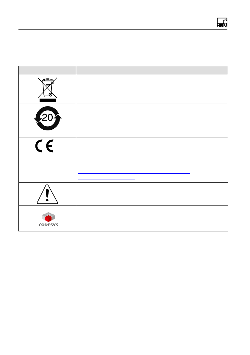
2 Symbols on the device
Symbol Meaning
Statutory waste disposal mark
See chapter 28, „Waste disposal and environmental protec
tionpage 539
Statutory mark of compliance with emission limits in electronic
equipment supplied to China
See chapter
tion
“, page 539
CE mark
The CE mark is used by the manufacturer to declare that the
product complies with the requirements of the relevant EC
directives (the Declaration of Conformity can be found at
http://www.hbmdoc.com/en/industrial-amplifiers/
pmx.html?geoip_cn=none
Take details in the operating manual into account.
CODESYS is a software platform for programmable logic
controllers. The license for CODESYS is already
implemented in WG001 basic housings.
28, „Waste disposal and environmental protec
20 A4354-2.2 HBM: public PMX
Page 21

3 User information
Important
Obsolete documentation !
If you use an obsolete version of this document or an
obsolete version of any of the documentation it mentions,
this may result in the product being mounted and
operated incorrectly.
Make sure that all the documents you possess and
use are always the current version. The current
documentation version for your HBM products can be
found at http://www.hbm.com/en/menu/products/industrial-
amplifiers/pmx/
3.1 Using this manual
► Read this operating manual thoroughly and in full
before operating the device for the first time.
User information
► Look upon this operating manual as part of the
product and keep it so that it is accessible to all users,
all of the time.
► If you pass the device on to a third party, always pass
it on together with the requisite documentation.
Should you lose this manual, the current version can be
found on our website, at http://www.hbm.com/en/menu/
products/industrial-amplifiers/pmx/
Failure to comply with this manual can result in personal
injury or damage to equipment.
We can assume no liability for any damage arising
from non-compliance with this operating manual.
PMX A4354-2.2 HBM: public 21
Page 22

User information
To help you quickly find the information you require, there
is a full list of contents right at the front of this operating
manual.
There is also a comprehensive index at the end of the
manual, where you can look for individual keywords.
3.2 About the PMX documentation
The documentation of the PMX measuring amplifier
system comprises
S This operating manual in PDF format
S A printed quick start guide for initial start-up
S A printed summary of the safety instructions
S The specifications (data sheet) in PDF format
S A PDF version of the web server Online help.
The complete description of the functionalities and
operation can be found in the Online help of the PMX
web server.
Important
These documents can be found
on the PMX system CD supplied with the device
always up-to-date, on our website, at http://www.hbm.
com/en/menu/products/industrial-amplifiers/pmx/
You can find additional information at http://www.hbm.
com/en/menu/support/software-firmware-downloads/indus
trial-amplifiers/ regarding e.g. device description files for
the realtime Ethernet cards (PROFINET / EtherCat) and
configuration examples.
22 A4354-2.2 HBM: public PMX
Page 23
You can find additional information at http://www.hbm.
com/en/menu/products/industrial-amplifiers/pmx/ ,as well
as a PMX video tutorial.
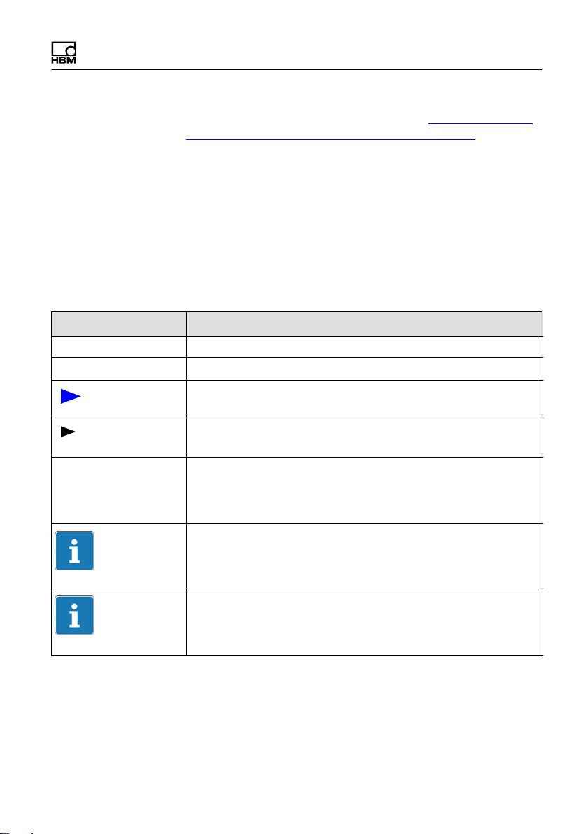
3.3 Symbols used in this manual
So that you can start working quickly and safely with your
product, the symbols and terms used in this manual are
standardized and are explained below (see Chapter 28
Waste disposal and environmental protection).
Symbol Significance
-
List
List (second level)
Cross-reference to another point in this
document or to other documents
This prompts you to take action (a single,
independent action)
User information
1.
2.
3.
Important
Tip
PMX A4354-2.2 HBM: public 23
Carry out this sequence of actions in the
given order.
Important information
This draws your attention to important information
about the product or about handling the product.
Information/Application instructions
Practical tips or other useful information for you.
Page 24

PMX product description
4 PMX product description
By buying the PMX measuring amplifier system, you
have chosen a high-quality HBM measurement system
that is compact, powerful and variable. The data rate for
all the measurement and calculation channels is 19,200 /
38,400 measurements per second. The device thus
achieves an overall processing rate of approx. 400,000
measured values per second.
Numerous different measurement, control and
automation tasks can be resolved with this measurement
system.
Connection to a PC (HOST)
The PMX measuring amplifier system is connected to a
PC via the standard ETHERNET interface, and can be
parameterized and operated via the internal web server.
The link to an automation system can be connected via
digital and analog inputs/outputs, as well as over the
fieldbus interfaces of the PMX, to a control (PLC) or a
primary automation system.
Internal calculation channels
The PMX has 32 internal calculation channels as
standard, which are freely available for evaluations and
mathematical measurement signal calculations.
Automation tasks from peak values to PID controllers can
be implemented simply and elegantly.
24 A4354-2.2 HBM: public PMX
Page 25

PMX product description
The following types of plug-in card are available:
PX401
S The PX401 measurement card offers four individually
configurable current or voltage inputs with TEDS
sensor detection.
S Extreme accuracy is guaranteed, as all the channels
have their own A/D converter with 24-bit resolution.
This also allows the acquisition of all the channels to
be totally synchronized.
PX455
S The PX455 measurement card is available for
measurement with strain gages (SG) and also has
four channels with 24-bit resolution and TEDS sensor
detection.
S The measurement card is suitable for strain gages in
both half bridge and full bridge circuits, as well as for
inductive transducers in half bridge and full bridge
circuits, LVDTs, potentiometric sensors and PT100
resistance thermometers.
PX460
S The frequency measurement card PX460 can be used
to operate torque flanges (torque, speed, angle of
rotation), angle/incremental encoders, SSI/PWM
sensors and frequency measurements up to 2 MHz.
Channels 1 and 3: Frequency measurement (fixed)
Channels 2 and 4: Frequency (digital, inductive),
counter, encoder, SSI, PWM (adjustable)
PMX A4354-2.2 HBM: public 25
Page 26

PMX product description
The following measurement modes are available:
- Up to four torque flanges (T10, T12, T40) for torque
or speed measurement (without direction of rotation
detection)
- Or two measuring channels for simultaneous
measurement of speed and angle (with direction of
rotation detection)
- Or one measuring channel for simultaneous speed,
angle and direction of rotation or reference pulse
detection
- Or two angle/incremental encoders each, SSI/PWM
sensors, magnetic transducers or pulse counters
- Or four measuring channels for frequency
measurement up to 2 MHz, incl. two shunt
calibrations and two 1-Wire TEDS (sensor
detection)
PX878
S The PX878 input/output card has a total of eight digital
inputs, eight digital outputs and five analog voltage
outputs. The PMX can be controlled by this or be
operated with a downstream controller (PLC). All real
or calculated measurement signals can be freely
assigned to the outputs.
PX01EC, PX01PN and PX01EP
S These interface cards can be optionally included in
the PMX, enabling operation of the PMX in an
automation system via the interface formats
EtherCat
, PROFINET or EtherNet/IP. Only one
variant can be used in each case.
26 A4354-2.2 HBM: public PMX
Page 27

PMX product description
Connection technique
Transducers are connected to the amplifiers via plug
terminals.
Plug terminals using push-in technology are available as
standard, with a screw-on system also available as an
option. If required, both types can be coded with the
enclosed coding pins to prevent mix-ups.
TEDS (Plug&Measure)
PMX amplifiers support TEDS (Transducer Electronic
Data Sheet, IEEE1451.4). When transducers are
connected, they are automatically detected. This
efficiently minimizes setup times and user error.
PMX web server
An easy to operate web server that is specifically tailored
to the PMX and is suitable for the measurement cards, is
integrated into the device for configuration, data
acquisition and visualization.
This gets you quickly to your measurement result, where
you can visualize the measured data and view them at a
later date.
PC software catman®EASY/AP
The HBM catman® software can be used to acquire,
condition and analyze the PMX measurement data, as an
option. This allows vast quantities of measurement data
to be displayed (stripchart function), analyzed and
exported in the most commonly used formats.
PMX A4354-2.2 HBM: public 27
Page 28

PMX product description
Software driver
The PMX command set and a dotNET-API are available
to create customer-specific interfaces. This allows your
own operating concepts and the inclusion in existing
software solutions to be realized.
With the PMX-LabView driver, PMX can be integrated via
Virtual Instruments (VI) in the software of National
Instruments.
LabVIEW is a registered trademark of National
Instruments.
Device implementation
The multi-client capability of the PMX makes it possible to
access the device simultaneously and without loss of
speed via all the interfaces - including web server, field
bus and analog outputs.
Calibration certificates
Documented quality: at the time of delivery, PDF docu
ments of the HBM calibration certificates for the fitted
measurement cards, and a certificate of compliance as
per EN 10204 2.1 are already stored in the PMX device
memory. The PMX browser can be used to download
them.
28 A4354-2.2 HBM: public PMX
Page 29
Model overview, scope of supply, accessories
5 Model overview, scope of supply, accessories
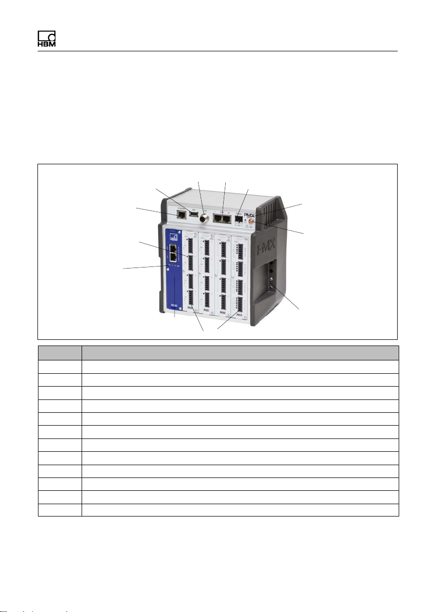
5.1 The PMX system
The PMX is a modular and universally applicable
measuring amplifier system.
6
7
5
8
4
3
2
1
12
Nr Bezeichnung
1 Communication card: EtherCAT or PROFINET; EtherNet/IP
2 Fieldbus status LEDs
3 Measurement card status LED
4 RJ45‐Ethernet socket to PC/Network
5 USB Host
6 CANbus (WGX001 only)
7 2x RJ45 socket for synchronization of up to 20 modules
8 10 … 30V voltage supply
9 System status LED
10 Ground
11 Positioning for the support rail
12 Max. 4 measurement card or input/output cards, e.g. : PX455, PX460, PX878, PX401
9
10
11
PMX A4354-2.2 HBM: public 29
Page 30

Model overview, scope of supply, accessories
The PMX comprises
- Basic device
- Measurement cards
- I/O cards and
- Communication cards.
The measurement cards, input/output cards and commu
nication cards can be individually combined and intelli
gently configured, in accordance with the measurement
task.
The PMX system is a modular and universally applicable
measuring amplifier system. The measurement cards,
input/output cards and communication cards can be
individually combined and intelligently configured in
accordance with the measurement task.
Basic device
Connections Description
ETHERNET Connection to an Ethernet network or a PC, 100 MBit/s; half
and full duplex
USB Device backup, data storage and special device functions
CAN Local connection to CANBus nodes (WGX001 only)
SYNC Synchronization of up to 20 PMX devices
POWER Voltage supply (10 … 30 V DC)
30 A4354-2.2 HBM: public PMX
Page 31

Model overview, scope of supply, accessories
Measurement cards
Measurement card Description Transducers that can be
connected
PX401
Current/voltage
amplifier
4 Current/voltage sources, always
individually user-selectable
between current and voltage input,
TEDS (1-wire)
PX455
Strain gage amplifier
4 SG full or half bridges (CF). The
bridge excitation voltage is 2.5 V
Inductive full or half-bridges
LVDT, potentiometric sensors,
piezoresistive sensors, TEDS
(0-wire)
PX460 Frequency/counter
measuring amplifier
Up to four torque flanges (T10,
T12, T40) for torque or speed
measurement (without direction of
rotation detection)
Or two measuring channels for
simultaneous measurement of
speed and angle (with direction of
rotation detection)
Or one measuring channel for
simultaneous speed, angle and
direction of rotation or reference
pulse detection
Or two angle/incremental encoders
each, SSI/PWM sensors, magnetic
transducers or pulse counters
Or four measuring channels for
frequency measurement up to 2
MHz, incl. two shunt calibrations
and two 1-Wire TEDS (sensor
detection)
PMX A4354-2.2 HBM: public 31
Page 32

Model overview, scope of supply, accessories
Input/output cards (I/O)
Basic device, model Interfaces Transducers that can be
connected
PX878 I/O card 8 digital inputs, 8 digital outputs,
5 analog voltage outputs, all
individually configurable
Communication cards
Module Interface Description
PX01EC EtherCAT®1) module EtherCAT slave
PX01PN PROFINET‐IO module PROFINET RT/IRT device
PX01EP EtherNet/IP module EtherNET/IP communication adapter
1)
EtherCAT® is a registered brand and patented technology, licensed by Beckhoff Automation
GmbH, Germany
32 A4354-2.2 HBM: public PMX
Page 33

Model overview, scope of supply, accessories
Overview of measurement cards and input/output card
PMX A4354-2.2 HBM: public 33
Page 34

Model overview, scope of supply, accessories
5.2 Scope of delivery
Order No.
1 PMX basic device, with a wall mounting kit (1 wall bracket, 4
screws, 4 washers) and a set for DIN rail mounting
with CAN connection and CODESYS‐V3 Soft‐PLC
without CAN connection, without CODESYS
For each measurement card : A mating connector for each
channel, all mating connectors with Push-In technology
(4 connectors are enclosed for each measurement card,
complete with coding pins)
DIN rail mounting
(2 units, packed in film cushion packaging with the mounting
material in an Etimex bag)
(4 M5x10 close tolerance screws, 4 spring washers)
PMX system CD with operating manual and data sheet, safety
instructions and quick start guide
For WGX001: Delivery with CODESYS‐CD (CODESYS‐V3
software, PMX package quick start guide and program
examples)
Mating connector M12x1 for CAN interface for WGX001 1-CON-S1002
Mating connector for PMX voltage supply (WGX001 / WGX002) 1-CON-S1010
1-WGX001
1-WGX002
1-CON-S1008
1-CON-S1012 for
PX460
1-RAILCLIP
5.3 Accessories
Accessories Order No.
Ethernet crossover cable, for direction operation of devices on a
PC or notebook, length 2 m, type CAT5+
AC/DC power supply unit;
Input: 90 V … 264 VAC, 1.5 m cable, output: 24 V DC, max.
1.25 A, 2 m cable with ODU plug
34 A4354-2.2 HBM: public PMX
1-KAB239-2
1-NTX001
Page 35

Model overview, scope of supply, accessories
Spare parts Order No.
PX01, PMX blue blanking plate for plug‐in card slot 0 1-PX01
PX02, PMX gray blanking plate for plug‐in card slot 1-4 1-PX02
RAILCLIP, PMX DIN rail mounting set (2 pieces), incl. screws 1-RAILCLIP
Phoenix plug terminals
Set of plug terminals (push‐in) for PMX plug‐in cards (4 x
7‐pin, incl. coding plug and labeling sheets)
Set of screw terminals for PMX plug‐in cards
(4 x 7‐pin, incl. coding plug and labeling sheets)
Set of screw terminal for PMX voltage supply
(1 x 2‐pin, incl. coding plug and labeling sheets)
Set of plug terminals (push‐in) for PMX plug‐in cards (2 x
13‐pin and 2 x 2‐pin, incl. coding plug and labeling sheets)
Mating connector M12x1 for CAN interface for WGX001
1-CON-S1008
1-CON-S1009
1-CON-S1010
1-CON-S1012
1-CON-S1002
In general, the mating connectors are always included for
all plug-in cards (PX401, PX455, PX460 and PX878).
When ordering a PMX basic device, the delivery always
includes DIN rail mounting and wall mounting elements.
Important
You have the option to retrofit or subsequently remove
measurement cards, I/O cards and communication cards.
PMX A4354-2.2 HBM: public 35
Page 36

Model overview, scope of supply, accessories
5.4 PMX web server/software
A PMX web server, including Help, is integrated in the
device. The web server also has a firmware loader
function, which can transfer new PMX firmware and web
server versions to the PMX.
An online Help is integrated into the web server to supp
ort PMX operation and handling (click on the Help icon,
top right in the overview menu).
36 A4354-2.2 HBM: public PMX
Page 37

Model overview, scope of supply, accessories
PC software catman®EASY/AP
The HBM catman® software can be used to acquire,
condition and analyze the PMX measurement data, as an
option. This allows vast quantities of measurement data
to be displayed (stripchart function) and analyzed (see
following ).
All real and calculated measurement channels, as well as
digital inputs/outputs can be measured. Digital inputs/
outputs are displayed as binary coded values.
PMX A4354-2.2 HBM: public 37
Page 38

Model overview, scope of supply, accessories
PMX supports up to three sampling rates that can be
independently set. These sampling rates can then be
assigned individual measurement signals.
Times of day, digital inputs/outputs of the PMX or
triggering via limit values can be used to start/stop
(trigger) a measurement.
The PMX can also be partially parameterized with
catman®. This includes:
S Setting the sensor type via the sensor database or
TEDS
S Writing the TEDS sensors via the integrated TEDS
EDITOR in catman®
S Zero setting the measurement signal and setting the
filter frequency for each individual channel
You can use the catman
®
Script programming language
to program complete measurement sequences including
automated storage of measured data and creation of
logs.
For more information, see the online Help in
catman®EASY/AP
Important
The PMX device settings are permanently saved in the
active PMX parameter set by catman®. The sensor set
tings (sensor type, scaling and filter) are automatically
changed by catman
® in PMX. This cannot be locked
either in catman ® or in PMX.
®
Before starting catman
filter setting in the catman
activate retaining of the PMX
®
option dialog (under DAQ
channels: "Allow manual filter settings").
For firmware version 2.00 and later, catman
®
version 4.0
or higher is mandatory.
38 A4354-2.2 HBM: public PMX
Page 39

Model overview, scope of supply, accessories
Software driver
The PMX command set and a dotNET-API and a
LabView driver are available to create customer-specific
interfaces. This allows your own operating concepts and
the inclusion in existing software solutions to be realized.
With the PMX-LabView driver, PMX can be integrated via
Virtual Instruments (VI) in the software of National
Instruments.
The following functions are supported by the drivers in
PMX:
Function Description
Decice Scan Scan Ethernet network
Measurement configuration Set sample rate, filter, zero
Sensor configuration Set scaling (2‐point) or via TEDS
Analog In DAQ and calculated channels
(streaming)
Status information (diagnostic) Read each channel‐ and device status
Peak values Read or clear peak values
Limit switches Read or set limit switches
Analog Out (direct setting) Read or set analog outputs (10 V)
Analog Out (configuration) Set source, scaling
Digital In DAQ Read digital outputs and set (high/low)
Digital Out DAQ (direct setting) Read digital outputs and set (high/low)
CAN DAQ (via CODESYS / calculated
channels)
Parameter sets Read and select parameter sets
Read all measuring values and time
stamps from sensors, channels
Read calculated channels with CAN
signals
PMX A4354-2.2 HBM: public 39
Page 40

Model overview, scope of supply, accessories
Notice
For firmware version 2.00 and later, catman®version 4.0
or higher is mandatory.
Tip
All commands of the PMX command set can be used as
lowlevel commands (see chapter 21) .
You can find extensive support and programming ex
amples in the program help for the individual drivers:
All drivers and the catman
downloaded from the HBM website as a free 30day ver
http://www.hbm.com/en/menu/support/software-
sion:
firmware-downloads/daq-software/catman/
®
software as well can be
40 A4354-2.2 HBM: public PMX
Page 41

Degree of protection / housing / shielding design
6 Degree of protection / housing / shielding
design
The degree of protection given in the specifications
indicates the suitability of the device for various ambient
conditions and also the protection it gives people against
potential risks when they are using it. The letters IP
(International Protection), which are always present in the
designation, are followed by two digits. These indicate
which degree of protection a housing offers against
contact or foreign bodies (first digit) and moisture (second
digit).
All PMX modules and the basic device are designed with
degree of protection IP20 (as per EN 60529).
IP 2 0
Code index Degree of
protection
against contact
and foreign
bodies
2 Protection against
contact with fingers,
protection against
foreign bodies with
> 12 mm
Code index Degree of
protection
against water
0 No water protection
PMX A4354-2.2 HBM: public 41
Page 42

Degree of protection / housing / shielding design
New Greenline shielding design
To improve electromagnetic interference protection, HBM
has developed an effective measure, the Greenline
shielding design. The shield is connected to the
connector housing. Appropriate routing of the cable
shield means that the entire measuring chain is
completely enclosed by a Faraday cage.
wh
bk
rd
bu
gn
gy
ye
Fig. 6.1 Greenline shielding design
Important
Use standard HBM cables for connecting the
transducers. When using other shielded, low-capacitance
measurement cables, attach the shield of the transducer
cable to the ground connection provided on the multipoint
connector, in accordance with HBM Greenline
information http://www.hbm.com/Greenline
.
This results in greater EMC protection.
42 A4354-2.2 HBM: public PMX
Page 43

Mounting/Dismounting/Replacing
7 Mounting/Dismounting/Replacing
7.1 Mounting tools and tightening torques
Mounting Required tool Tightening torque
Fasten Rail-Clip to support rail
M 2.5 hexagon socket screw
Mounting DIN rail on housing
M5 hexagon socket screw
Mounting front panel
M2.5 Torx screws
Mounting wall bracket
M4 hexagon socket screw
Mounting side parts
M3 Torx screws
Grounding screw on the PMX
M4 Torx screws
Hexagon socket
screwdriver
2.5 a.f.
Hexagon socket
screwdriver
3 a.f.
Torx screwdriver
TX8
Hexagon socket
screwdriver
3 a.f.
Torx screwdriver
TX10
Torx screwdriver
TX20
1.0 - 1.2 Nm
3 Nm
0.5 - 0.6 Nm
1.5 … 2 Nm
0,8 … 1 Nm
1,5 … 2 Nm
PMX A4354-2.2 HBM: public 43
Page 44

Mounting/Dismounting/Replacing
7.2 Support rail mounting
75 mm
2
Allen screw
3 mm a.f.
1
3
A
B
3
4
D
Fig. 7.1 Mounting on a support rail
► Undo the four back-panel screws (Torx T10) (1)
► Slide the side parts forward
► Screw on the support rail mounting (Rail-Clip) (3)
(approx. 5 Nm) in a choice of four positions (A to D)
(two positions for the 7.5 mm support rail)
► Screw the side panels (2) back on
► Hook the PMX device into the support rail (4)
(2)
C
44 A4354-2.2 HBM: public PMX
Page 45

Mounting/Dismounting/Replacing
Important
Device damage caused by the PMX falling due to resis
tance in hooking/unhooking the PMX.
HBM recommends using a DIN support rail (DIN EN
60715), 15 mm in height. When using a smaller support
rail (7.5 mm high), it should be shimmed to make it easy
to hook/unhook the PMX device.
The 7.5 mm support rail can only be used in the top two
positions (A and B).
Attach the support rail mounting (Rail-Clip) to the
DIN rail
Allen screw
2.5 a.f.
At the time of delivery, the self-locking (2.5 mm a.f.) Allen
screws are unscrewed as far as the stop.
► Clip on the support rail mounting (Rail-Clip)
PMX A4354-2.2 HBM: public 45
Page 46

Mounting/Dismounting/Replacing
► Hand-tighten the self-locking Allen screw (1 - 1.2 Nm)
Important
Device damage caused by electromagnetic irradiation of
external devices.
Faulty measurements due to electromagnetic irradiation
from other devices.
To ensure adequate grounding for the PMX, the support
rail must be connected to a functional earth
Both the DIN rail and the PMX must be free of paint,
varnish and dirt at the point of installation.
► Connect the PMX housing to ground via the grounding
screw.
.
46 A4354-2.2 HBM: public PMX
Page 47

Mounting/Dismounting/Replacing
Dimensions and mounting instructions
200
141
*) Height of support rail 15 mm
**) Height of support rail 7.5 mm
***) Min. dimension: Plug plus sensor cable
NOTE:
To ensure sufficient ventilation/cooling, a 2 cm gap must
be maintained above and below neighboring devices.
200
141*)
variable
133.5**)
122
min. 25***)
PMX A4354-2.2 HBM: public 47
Page 48

Mounting/Dismounting/Replacing
7.3 Wall-mounting
4. 3
1
225
168.5
215
Fig. 7.2 Mounting on a wall
152
► Attach the wall bracket at the back of the PMX with
the enclosed M4 screws (1) (3 Nm)
48 A4354-2.2 HBM: public PMX
Page 49

Mounting/Dismounting/Replacing
Screw
M4
Screw
M4
Screw
M4
Grounding
screw
(Torx TX20)
Screw
M4
► Screw the complete unit to a wall; hole Ø 4 mm
Notice
Device damage caused by electromagnetic irradiation of
external devices.
Faulty measurements due to electromagnetic irradiation
from other devices.
The housing must also be connected to a functional earth
in a wall mounting.
► Connect the PMX housing to ground via the grounding
screw.
PMX A4354-2.2 HBM: public 49
Page 50

Mounting/Dismounting/Replacing
Dimensions and mounting instructions
215
152
138
200
min. 25*)
122
*) Min. dimension: Plug plus sensor cable
NOTE:
To ensure sufficient ventilation/cooling, a 2 cm
gap must be maintained above and below
neighboring devices.
7.4 Replacing measurement and
communication cards
Measurement and communication cards can be
retrofitted or removed at a later date. Please note the
combination options (see chapter 8.2.1 on page 55).
After modification and switching on the supply voltage,
the PMX automatically detects and initializes the
hardware configuration. The factory settings are loaded.
All parameters must be reentered, also for the existing
cards.
50 A4354-2.2 HBM: public PMX
Page 51

Mounting/Dismounting/Replacing
Notice
If the measurement or communication cards are
incorrectly removed/replaced, they may be damaged
or destroyed.
These cards must be de-energized before they are
removed or replaced
► Always disconnect the PMX from the power supply
before removing a card. Note that the device settings
have to be re-parameterized if new cards are added.
The instructions below must also be followed:
Removal
1
1. Undo the three M2.5x8 Torx (Tx8) screws (1) of the
card/blanking plate
2. Use a screwdriver to slightly lever up the card at the
lug provided.
3. Carefully take out the board
PMX A4354-2.2 HBM: public 51
Page 52

Mounting/Dismounting/Replacing
Installation
1. Carefully insert the board into the PMX slot (ribs
prevent tilting)
2. The board centers itself in the VG strip at the back
3. Re-tighten the three M2.5 screws
Notice
Device damage caused by electromagnetic irradiation of
external devices.
Faulty measurements due to electromagnetic irradiation
from other devices.
► Close the open module slots with blanking plates
(Accessories).
52 A4354-2.2 HBM: public PMX
Page 53

8 Electrical connections PMX
8.1 Plug technology and clamping areas
All PMX plug-in cards (PX401, PX455, PX460, PX878)
are delivered as standard with easy to fit plug terminals
using Push-In technology. Plug terminals can also be
delivered with a screw-on system as an option.
Push-In technology
The clamping area is 0.2mm2 (AWG24) to 1.5mm2
(AWG16). If several conductors are to be connected to a
terminal, the line cross-section must be adapted
accordingly. End sleeves (without plastic collars, 10mm)
should be used on the strands to connect the wires to the
terminals.
Electrical connections PMX
The shield of the transducer cable must be connected to
the ground connection provided on the PMX multipoint
connector, in accordance with HBM Greenline informa
tion http://www.hbm.com/Greenline
Important
The grounding terminal on the PMX is not a protective
ground (optional connection).
The measurement system is fitted with an automatic
current limiter for each device card, as well as for the
PMX basic device.
PMX A4354-2.2 HBM: public 53
.
Page 54

Electrical connections PMX
8.2 Overview of PMX functions
1
11
10
9
8
Ethernet plug for PC/network connection
1
2
USB host, e.g. for a memory stick
CAN for CAN driver, M12, option
3
(WGX001)
2 x RJ45 for synchronization
4
Excitation 10 . . . 30 V DC
5
6
Device status - LED
4
2
3
5
6
7
7
Measurement cards (PX401, PX455, PX460)
7
and/or PX878 I/O card or blanking plate
8
LED Measurement card status
Communication cards:
9
PX01EC (EtherCAT®, PX01PN
(PROFINET-IO, PC01EP EtherNet/IP) or
blanking plate
10
DIN rail positioning
Fieldbus LED
11
54 A4354-2.2 HBM: public PMX
Page 55

Electrical connections PMX
8.2.1 Combination options
Slot
0
Fieldbus or
blanking plate
PX401 - x x x x 0 - 4
PX455 - x x x x 0 - 4
PX460 - x x x x 0 - 4
PX878 - x x - - 0 - 2
x - - - - 0 - 1
Slot
1
Slot
2
Slot
3
Slot4Number
of
plug-ins
8.2.2 Relevance of the basic device connection
sockets
PC or network connection.
Cable: Ethernet cable CAT5, SFTP
USB connection version 2.0 e.g. for mass storage device,
scanner, USB stick
Cable: standard USB cable
PMX A4354-2.2 HBM: public 55
Page 56

Electrical connections PMX
Synchronization of several (max. 20) PMX devices via
two RJ45 sockets.
See chapter 8.1
Supplying voltage to the PMX by connecting a separate
DC voltage supply.
-
+
(view of device front)
PMX basic device
3
4
5
1
2
Cable
Connector
Female connector
CAN connection (type WGX001 only)xx
Pin Signal Description
1 SHLD CAN shielding
2 not connected
3 GND Ground
4 CAN_H CAN_H data lead (high)
5 CAN_L CAN_L data lead (low)
56 A4354-2.2 HBM: public PMX
Page 57

Electrical connections PMX
8.2.3 LEDs for system monitoring (device LED)
Basic device (WGX001/002)
12
3456 7
ETHERNET LED (1, 2)
LED LED Status Significance
Ethernet Link (1)
Ethernet RX / TX (2)
green
yellow
Steady Connection is present
Flashing Data are being transmitted
SYNC IN / OUT (3, 4 and 5, 6)
LED LED Status Significance
IN (3)
IN (4)
IN (3 + 4) Off Master
OUT (5)
OUT (6)
green
yellow
green
yellow
On Slave
On Error
On always on
Error (always identical to the
On
right-hand LED of the IN
socket)
PMX A4354-2.2 HBM: public 57
Page 58

Electrical connections PMX
SYS LED (7)
LED Status Significance
green
On
Off
Voltage supply available
Voltage supply missing
yellow
red
On Device is booting
Flashing
On
8.2.4 Fieldbus LED
PX01EC
Serious internal error or
Firmware update
2
1
58 A4354-2.2 HBM: public PMX
Page 59

Electrical connections PMX
EtherCAT®
LED LED Status Significance
ERR
red
red
red
red
red
LED LED Status Significance
RUN
green
green
green
Off No error
Flashing Configuration error
Single flash Synchronization error
Double flash Application timeout error
On PDI timeout error
Off INIT status
Flashing PRE OPERATIONAL status
Single flash SAFE OPERATIONAL status
green
On OPERATIONAL
PMX A4354-2.2 HBM: public 59
Page 60

Electrical connections PMX
LED LED Status Significance
1
2 - - No function
green
Permanently
on
Flashing
Off
Connection established
Send / Receive
No connection
60 A4354-2.2 HBM: public PMX
Page 61

Electrical connections PMX
PX01EP
EtherNET/IP
LED LED Status Significance
Connected: If the device has at least
LV
green
On
Flashing
green
On
red
one existing connection (even to the
message router), the network status
display will light up and remain green.
No connections: If the device has no
existing connections, but has received
an IP address, the network status
display flashes green.
Double IP*: If the device detects that
the IP address has already been used,
the network status display lights up and
remains red.
2
1
PMX A4354-2.2 HBM: public 61
Page 62

Electrical connections PMX
Connection time-out: If one or more of
the connections to this device are in
time-out, the network status display
red
green
red
-
LED LED Status Significance
MS
green
green
red
red
Flashing
Flashing
Off
On
Flashing
Flashing
Flashing
flashes red. This status is only
terminated when all connections in time-
out have been restored or when the
Self-test: The network status display
flashes green/red when the device is
carrying out a self-test.
Not switched on, no IP address: If the
device has no IP address (or is switched
off), the network status display does not
Device operational: If in operation and
running correctly, the network status
display will light up and remain green.
Standby: If the device has not been
configured, the module status display
Serious error: If the device detects a
serious error that cannot be rectified, the
module status display lights up and
Simple error*: If the device detects a
serious error that cannot be rectified, the
module status display lights up and
NOTE: A faulty or inconsistent
configuration is classified, e.g. as a simple
SignificanceStatusLEDLED
device is reset.
light up.
flashes green.
remains red.
remains red.
error.
62 A4354-2.2 HBM: public PMX
Page 63

Electrical connections PMX
SignificanceStatusLEDLED
Self-test: The module status display
green
red
-
LED LED Status Significance
Flashing
Off
flashes green/red when the device is
carrying out a self-test.
Not switched on: If the device is not
switched on, the module status display
does not light up.
1
2
green
-
yellow
On Connection to Ethernet established
Off
Flashing
The device has no connection to the
Ethernet
The device is sending/receiving Ethernet
frames
PMX A4354-2.2 HBM: public 63
Page 64

Electrical connections PMX
PX01PN
2
P2
Port 2
Port 1
P1
PROFINET
LED LED Status Significance
On
SF
BF
LED LED Status Significance
1
2 - - No function
red
red
green
Flashing
On
Flashing
Permanently on
Flashing
Off
System error, incorrect configuration
Flashing for device detection is controlled
by the IO controller
No connection or no configuration
Bus error, incorrect configuration, not all
IO devices are connected
Connection established
Send / Receive
No connection
1
64 A4354-2.2 HBM: public PMX
Page 65

Electrical connections PMX
8.2.5 Measurement card LEDs
PX401, channel status
Status LED
LED Status Significance
green
yellow
red
On no errors
Flashing Firmware update
Parameter not OK,
On
overloaded
PMX A4354-2.2 HBM: public 65
Page 66

Electrical connections PMX
PX455, channel status
Status LED
LED Status Significance
green
yellow
red
On no errors
On
Flashing
On
No transducer connected or wire break (self-
calibration ongoing)
Firmware update
Parameter not OK, transducer error,
overloaded
66 A4354-2.2 HBM: public PMX
Page 67

Status LED
Electrical connections PMX
PX460, channel status
LED Status Significance
green
yellow
red
On no errors
On
Flashing
On
No transducer connected or wire break or
firmware update
Parameter not OK, transducer error,
overloaded
PMX A4354-2.2 HBM: public 67
Page 68

Electrical connections PMX
PX878
One status LED per channel
LED Status Significance
Digital
green
green
Analog
green
red
On
Off
On
Off
On
Off
On
Digital output: High
Digital output: Low
Digital input: High
Digital input: Low
Analog output configured
Analog output not configured
Analog output overloaded,
signal invalid
68 A4354-2.2 HBM: public PMX
Page 69

Electrical connections PMX
8.3 Supply voltage
Notice
Device damage caused by high voltages.
If you are using power supply 1NTX001 listed in the ac
cessories, note the enclosed safety instructions.
With a separate DC voltage power supply (10 to 30 V
DC, nom. 24 V, power output at least 20 W), the PMX
device is supplied with voltage via the POWER socket (1)
(see Chapter 11 Startup).
Measurement card
Basic device 3
PX401 0, 7 5
PX455 1,6
PX460 2
PX878 2
PX01EC (EtherCAT®) 2
PX01PN (PROFINET) 2,4
PX01EP (EtherNet/IP) 2,3
Power consumption [W]
for a 24 V supply voltage
+
-
1
PMX A4354-2.2 HBM: public 69
Page 70

Electrical connections PMX
8.4 Measurement cards / transducer
8.4.1 Intrinsically safe measurement circuits -
To operate transducers (load cells, force transducers,
etc.) in potentially explosive atmospheres, intrinsically
safe measurement circuits (Ex II (1) GD, [EEx ia]IIC)
must be set up on the PX455 by connecting safety
barriers (Zener barriers) type SD01A. The safety barriers
must also be mounted on the DIN rail like the PMX. An
ATEX test certificate must be available for the
transducers used. Transducers with 350 ohm bridge
resistance can be used. One transducer per
measurement channel of the PC455 can be operated
(parallel connection is not possible).
The PX455 offers 4 measurement channels with 4.8kHz
carrier frequency measurement. If the measurement
signals need to be added/subtracted or mean values
formed, this can be set using the internal PMX calculation
channels.
connection
Operation with Zener barriers
Important
In addition to the SD01A, the negative operating voltage
of the PMX must be grounded!
Cable lengths of up to max. 100 m are permissible. TEDS
cannot be used.
The measurement accuracy of the PX455 with operation
of the SD01A is max. 0.5%.
70 A4354-2.2 HBM: public PMX
Page 71

Electrical connections PMX
8.4.2 PX455
Four individually configurable 4 SG full or half
bridges (4.8kHz CF). Inductive full or half bridges,
LVDT, potentiometric sensors, piezoresistive
sensors, TEDS (0-wire), sensor detection
0‐wire TEDS
see Chapter 8.7.3
The bridge excitation voltage is 2.5 V.
PMX A4354-2.2 HBM: public 71
Page 72

Electrical connections PMX
8.4.2.1 Strain gage and inductive full and half
bridges (6-wire configuration)
SG and inductive full bridges
wh
Measurement
signal (+)
bk
Bridge excitation
voltage (-)
rd
Measurement signal (-)
bu
Bridge excitation
voltage (+)
gn
Sense lead (+)
gy
Sense lead (-)
ye
Cable shield
1
2
4
3
'
3
2'
SG and inductive half bridges
Plug terminal
Cable color code for HBM transducer cables:
wh= white; bk= black; bu= blue; rd= red; ye = yellow; gn= green; gy= gray
Transducer connection
Fig. 8.1 PX455 plug terminal in a six-wire circuit
wh
Measurement
signal (+)
bk
Bridge excitation
voltage (-)
bu
Bridge excitation
voltage (+)
gn
gy
Sense lead (-)
ye
Cable shield
Sense lead (+)
1
2
3
3'
2'
72 A4354-2.2 HBM: public PMX
Page 73

Electrical connections PMX
8.4.2.2 Strain gage and inductive full and half
bridges (4-wire configuration)
Four-wire connection:
full bridge
wh
bk
rd
bu
ye
Feedback bridges for a four-wire configuration
Cable color code: wh= white; bk= black; bu= blue; rd= red; ye = yellow; gn= green; gy= gray
1
2
4
3
3'
2'
Connection: Half bridge
wh
bk
bu
gn
gy
ye
Fig. 8.2 PX455 plug terminal in four/three-wire configuration
1
2
3
3'
2'
PMX A4354-2.2 HBM: public 73
Page 74

Electrical connections PMX
8.4.2.3 LVDT
LVDT transducer
Plug terminal
Transducer connection
Measurement signal (+)
Bridge excitation voltage (-)
Bridge excitation voltage (+)
Measurement signal (-)
Cable shield
Sense lead (+)
Sense lead (-)
Cable color code for HBM transducer cables:
wh= white; bk= black; bu= blue; rd= red; ye = yellow; gn= green; gy= gray
Hsg. = Housing
Fig. 8.3 PX455 plug terminal LVDT transducers
1
2
3
4
3'
2'
74 A4354-2.2 HBM: public PMX
Page 75

8.4.2.4 Potentiometric transducer
Potentiometric transducer
2
Electrical connections PMX
Measurement signal (+)
Bridge excitation
voltage (-)
Bridge excitation
voltage (+)
1
2
3
1
3
Cable shield
Sense lead (+)
Sense lead (-)
3'
2'
Fig. 8.4 PX455 plug terminal potentiometric transducer
Important
Transducer connection in a four/three wire
configuration:
When connecting a transducer in a four/three wire
configuration, the sense leads must be connected to the
corresponding bridge excitation circuit (PIN 2'-2 and
Pin 3'-3) by wire bridges, as otherwise a sensor error will
be detected.
TEDS functionality is not available when connecting in a
fourwire configuration.
PMX A4354-2.2 HBM: public 75
Page 76

Electrical connections PMX
8.4.2.5 PX455 with Pt100 temperature measurement
With the PX455 measurement module, temperatures can
be measured with an uncertainty of +/-1°C without an
external preamplifier. A 100 ohm precision resistor
(R_comp) with a maximum tolerance of 0.1% is added to
a Pt100 resistor to make a half bridge circuit. The PMX
calculated channel "Pt100 on PX455" converts the meas
ured bridge unbalance to degrees Celsius and performs a
corrective calculation appropriate to the sensor cable be
ing used (R_wire).
Good heat dissipation is essential to keep the measure
ment error caused by the self heating of the Pt100 as low
as possible! This can be done, for example, by mounting
it on a metallic body.
Important
76 A4354-2.2 HBM: public PMX
Page 77

Resistance thermometer
Electrical connections PMX
PX455
Measurement
signal +
Bridge excitation
voltage -
Bridge excitation
voltage +
Sense lead +
Cable shield
Sense lead -
Fig. 8.5 PX455 with PT100 element for temperature
measurement
1
2
3
3'
2
'
PMX A4354-2.2 HBM: public 77
Page 78

Electrical connections PMX
8.4.3 PX401
Four individually configurable current or voltage
inputs with 4 TEDS (1-wire) sensor detection.
1‐wire TEDS
see Chapter 8.7.3
IEPE sensors can also be operated in combination with
the Smart module (1-EICP-B-2).
78 A4354-2.2 HBM: public PMX
Page 79

Electrical connections PMX
8.4.3.1 Voltage source ± 10 V
TEDS
module
(optional)
Excitation for
external
transducers
U
1
2
+ U
TEDS
OUT +
OUT -
Cable shield
Fig. 8.6 PX401 plug terminal Voltage source ±10 V
PMX A4354-2.2 HBM: public 79
Page 80

Electrical connections PMX
8.4.3.2 Current source ± 20 mA
I
+ I
TEDS
module
(optional)
Excitation for
external
transducers
1
2
TEDS
OUT +
OUT -
Cable shield
Fig. 8.7 PX401 plug terminal Current source ±20 mA (4-wire
circuit)
80 A4354-2.2 HBM: public PMX
Page 81

TEDS-
module
(optional)
Electrical connections PMX
8.4.3.3 Current source ± 20 mA
+ I
I
1
2
TEDS
OUT +
OUT -
Sensor supply
comes from the
PX401
Sensor supply and measure
ment signal are sent through
a connection cable
Fig. 8.8 PX401 plug terminal Current source ±20 mA (2-wire
Cable shield
circuit)
PMX A4354-2.2 HBM: public 81
Page 82

Electrical connections PMX
Current-fed piezoelectric transducers, IEPE or IPC
transducers, are supplied with a constant current, e.g. 4
mA, and output a voltage signal that can be controlled
with the PX401 via an external module.
8.4.3.4 IEPE transducers with external measuring
amplifier
PX401
IEPE
BNC
PIN:
Smart modules
(1-EICP-B-2)
2
6
3
5
4
1
2 Data
3 No function
Signal +
(+)
Signal -
(-)
Cable shield
24 V
0 V
1-wire EEPROM (optional) view from below
123
wh
gn
bk
1
2
7
rd
5
6
PX401
2
4
Fig. 8.9 PX401 plug terminal lEPE transducers
82 A4354-2.2 HBM: public PMX
Page 83

Electrical connections PMX
8.4.3.5 PX401 with charge amplifier
Piezoelectric sensors can be operated with the PX401 via
external CMA or CMD charge amplifiers. The charge
amplifiers convert the sensor signal into a +/-10 V voltage
signal. The reset/operate charge amplifier signal can take
place in the PMX from an external controller or via a
PX878 digital output. The CMA charge amplifier can be
supplied directly by the PX401 measurement module.
Important
Due to the inrush current of the CMD charge amplifier,
the current feed of the CMD must be separate and not via
the PX401 measurement module.
PMX A4354-2.2 HBM: public 83
Page 84

Electrical connections PMX
Piezoelectric sensors with external charge amplifier
PX401
Charge cable
Piezoelectric sensor
PIN:
5
6
4
3
8
1
CMA
charge amplifier
Signal +
(+)
Signal -
(-)
TEDS transducer
identification
Cable shield
24 V
0 V
Measurement signal (reset)
gy
pk
ye
rd
wh
gn
1
2
4
7
5
6
PX878
1
5
6
PX401
Terminal 2
(digital
input/output)
Fig. 8.10 PX401 pin assignment with external charge amplifier
84 A4354-2.2 HBM: public PMX
Page 85

Electrical connections PMX
External transducers are supplied with power via the
PX401 measurement card (OUT + and OUT -). The
supply voltage is identical to the device supply voltage.
The maximum current is 400 mA per measurement card
and is distributed across the used transducers.
Important
The individual measurement channels on the PX401
measurement card are not electrically isolated from each
other. The PX401 measurement card has common elec
trical isolation from the basic device.
PMX A4354-2.2 HBM: public 85
Page 86

Electrical connections PMX
Channel
1
WGX basic device
PX401 housing
All four channels at one potential
Channel 4
Potential isolation
Fig. 8.11 Potential isolation PX401
86 A4354-2.2 HBM: public PMX
Page 87

Electrical connections PMX
8.4.4 PX460
Torque flanges (torque, speed, angle of rotation),
angle/incremental encoders, SSI/PWM sensors and
frequency measurements up to 2 MHz
Channels 1 and 3: Frequency measurement (fixed)
Channels 2 and 4: Frequency (digital/inductive), counter,
encoder, SSI, PWM (adjustable)
The following measurement modes are available:
- Up to four torque flanges (T10, T12, T40) for torque
or speed measurement (without direction of rotation
detection)
- Or two torque flanges for simultaneous torque and
rotational speed measurement (without direction of
rotation/angle of rotation measurement)
- Or one torque flange for simultaneous
measurement of torque, speed, angle and direction
of rotation or reference pulse detection
- Or two angle/incremental encoders each, SSI/PWM
sensors, magnetic transducers or pulse counters
- Or four torque flanges for frequency measurement
up to 2 MHz, incl. two shunt calibrations and two
1-Wire TEDS (sensor detection)
PMX A4354-2.2 HBM: public 87
Page 88

Electrical connections PMX
SSI
1‐wire TEDS
see Chapter 8.7.3
Notice
The sensors for the PX460 are supplied externally with
voltage with the contacts (IN + -). The PX460 card then
provides the supply for 24 V (OUT + - ) and 5 V (5 V
OUT).
The input signals fed from the sensor into the PX460
must not exceed max. ±12 V. Otherwise the measure
ment inputs of the PX460 may be destroyed.
A shunt can be operated via Pin7. It can be activated via
the PMX web browser or the PMX command /dot
NET‐API/Catman.
88 A4354-2.2 HBM: public PMX
Page 89

Electrical connections PMX
8.4.4.1 Voltage supply for signal transmitter and
transducer up to 24 VDC nominal (rated)
voltage.
NOTE
The input signals fed from the
sensor into the PX460 must not
max.. ± 12 V
max. ± 12 V
max. ± 12 V
exceed max. ±12 V. Otherwise
the measurement inputs of the
PX460 may be destroyed.
Sensor
input signals
looped through, protected, 2 A max.
Sensor supply
Nominal (rated) voltage
24 VDC
Feed sensor supply
+
max. 24 VDC
-
Fig. 8.12 PX460 Voltage supply options up to 24 VDC
nominal (rated) voltage
PMX A4354-2.2 HBM: public 89
Page 90

Electrical connections PMX
8.4.4.2 Voltage supply for signal transmitter and
5 VDC, 200 mA
transducer up to 5 VDC nominal (rated)
voltage
Sensor
supply
Nominal
(rated)
voltage
5 VDC
Feed sensor supply
+
10 … 24 VDC
-
Fig. 8.13 PX460 Voltage supply options up to 5 VDC nominal
(rated) voltage
90 A4354-2.2 HBM: public PMX
Page 91

Electrical connections PMX
8.4.4.3 Frequency measurement symmetrical
(differential)
GND
F1
F2
Transducer 1
Transducer 2
TEDS
2
1
module
(optional)
Shunt optional
Transducer excitation not shown
Twisted pair
Fig. 8.14 PX460 pin assignment two frequencies, differential
Possible channel setting via web server:
Transducer 1 : Frequency (digital), permanent
Transducer 2 : Frequency (digital), counter, PWM
PMX A4354-2.2 HBM: public 91
Page 92

Electrical connections PMX
8.4.4.4 Frequency measurement symmetrical
(single-pole)
F1
F2
Zero index
optional
GND
1
2
TEDS module (optional)
Transducer 1
Transducer 2
Shunt optional
Transducer excitation not shown
Fig. 8.15 PX460 pin assignment two frequencies, asymmetric
Possible channel setting via web server:
Transducer 1 : Frequency (digital), permanent
Transducer 2 : Frequency (digital), permanent, counter,
PWM
92 A4354-2.2 HBM: public PMX
Page 93

Electrical connections PMX
8.4.4.5 Encoder and incremental encoder,
symmetrical (differential)
F 1
F 2
Zero index
2
1
TEDS module
(optional)
Excitation,
external direct or
external via PMX
terminals
Twisted pair
Encoder
Fig. 8.16 PX460 pin assignment encoder, symmetrical
Possible channel setting via web server:
Transducer 1 : Frequency (digital), permanent
Transducer 2 : Frequency (digital), counter, PWM
PMX A4354-2.2 HBM: public 93
Page 94

Electrical connections PMX
8.4.4.6 Encoder and incremental encoder,
asymmetrical (single-pole)
Track 1, max. 12 V
Track 2, max. 12 V
Zero index, max. 12
V
GND
2
1
TEDS module
(optional)
Excitation,
external direct or
external via PMX
terminals
Encoder
Fig. 8.17 PX460 pin assignment encoder, asymmetrical
Possible channel setting via web server:
Transducer 1 : Frequency (digital), permanent
Transducer 2 : Frequency (digital), permanent, counter,
PWM
94 A4354-2.2 HBM: public PMX
Page 95

Electrical connections PMX
8.4.4.7 SSI encoder (active only)
*)
SSI Clock
1
SSI Encoder
2
SSI Data
2
1
TEDS module
(optional)
Excitation,
external direct or external
via PMX terminals
*) Additional frequency encoders can be connected to
terminals 1 and 2 and frequencies measured.
Fig. 8.18 PX460 pin assignment SSI encoder
Possible channel setting via web server:
Transducer: SSI
PMX A4354-2.2 HBM: public 95
Page 96

Electrical connections PMX
8.4.4.8 Inductive encoder or pulse encoder
(passive only)
*)
Do not carry any further signals in the
connection cable
TEDS
1
2
module
(optional)
Do not connect with voltage source!
*) Additional frequency encoders can be connected to
terminals 1 and 2 and frequencies measured.
Passive encoder /
pulse encoder
Fig. 8.19 PX460 pin assignment encoder and pulse encoder,
differential
Possible channel setting via web server:
Transducer: Frequency (inductive)
Important
This signal input is only designed for passive pulse
encoders.
96 A4354-2.2 HBM: public PMX
Page 97

Pin 7 not connected or connected as output:
If Pin 7 is connected as
input, both potential
ranges are connected
(see Chap. 8.4.4.8)
Shunt
PX460 housing
Electrical connections PMX
Shunt
Potential isolation
Fig. 8.20 Potential isolation PX460
PMX A4354-2.2 HBM: public 97
Page 98

Electrical connections PMX
8.4.4.9 Connection and configuration of the HBM
torque flange (T10, T12, T40)
T10 T12
T40
Connector 1
Connector 1
Connector 2
Connector 1: 1-KAB153-6 (torque)
Connector 2: 1-KAB154-6 (speed); 1-KAB164-6 (speed, angle)
Connector 2
Connector 2
Connector 1
Fig. 8.21 Connector positions T10, T12, T40
Assignment for connector 1: T10, T12, T40
Supply voltage and frequency output signal.
Device connector Connector
pin
1 Torque measurement signal
2 Supply voltage 0 V; bk
3 Supply voltage 18 V 30 V bu
4 Torque measurement signal
5 Measurement signal 0V, symmetric gy
6 Shunt signal trigger 5 V 30 V gn
Top view
6
1
2
7
5
3
4
7
1)
RS-422 complementary signals; with cable lengths exceeding 10 m, we
recommend using a termination resistor R = 120 ohms between the (wh) and (rd) wires.
2)
RS 422: Pin 1 corresponds to A, Pin 4 corresponds to B.
Assignment0V Wire color
(frequency output; 5 V
(frequency output; 5 V
Shunt signal
1),2)
1),2)
)
)
wh
rd
gy
Shielding connected to housing ground
98 A4354-2.2 HBM: public PMX
Page 99

Electrical connections PMX
Assignment for connector 2: T10, T12, T40
Rotational speed output signal, reference pulse
(optional).
Device connector Connector
Assignment Wire
pin
1 Speed measurement signal 1) (pulse string,
5 V; 0o)
2 Reference signal (1 pulse/revolution, 5 V1)) bu
3 Measurement signal speed (pulse string, 5 V;
phase shifted by 90o)
(pulse string, 5 V; 0o)
Top view
2
4
5
8
3
1
7
6
4 Reference signal (1 pulse/revolution, 5 V)
5 No function vi
6 Speed measurement signal
7 Measurement signal speed (pulse string, 5 V;
phase shifted by 90o)
8 Supply voltage zero bn
Shielding connected to housing ground
1)
RS-422 complementary signals; with cable lengths exceeding 10 m, we
recommend using a termination resistor of R = 120 ohms.
color
rd
gy
1)
bk
1)
wh
gn
PMX A4354-2.2 HBM: public 99
Page 100

Electrical connections PMX
Connection examples (torque flange):
Connector 1 (torque, torque flange 1 )
Connector 1 (torque, torque flange 2)
wh
rd
bu
bk
18 … 30 VDC
1
4
5
3
2
wh
gy
bu
bk
1
rd
4
5
3
2
TF 1
TF 2
Connector 1 (torque, torque flange 3) Connector 1 (torque, torque flange 4)
wh
rd
1
4
wh
gy
1
rd
4
5
TF 3
5
bu
3
bu
bk
18 … 30 VDC
3
2
bk
2
TF 4
Fig. 8.22 PX460 four torque flanges, torque only
100 A4354-2.2 HBM: public PMX
 Loading...