

Page 1
Mounting Instructions | Montageanleitung |
Notice de montage
English Deutsch Français
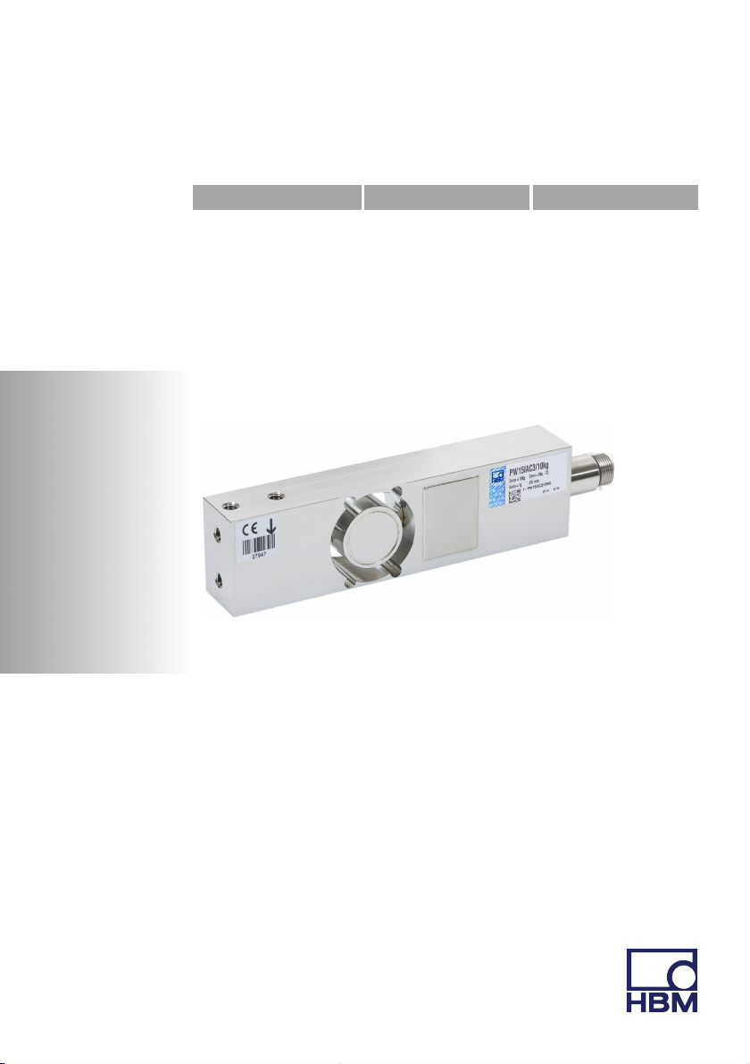
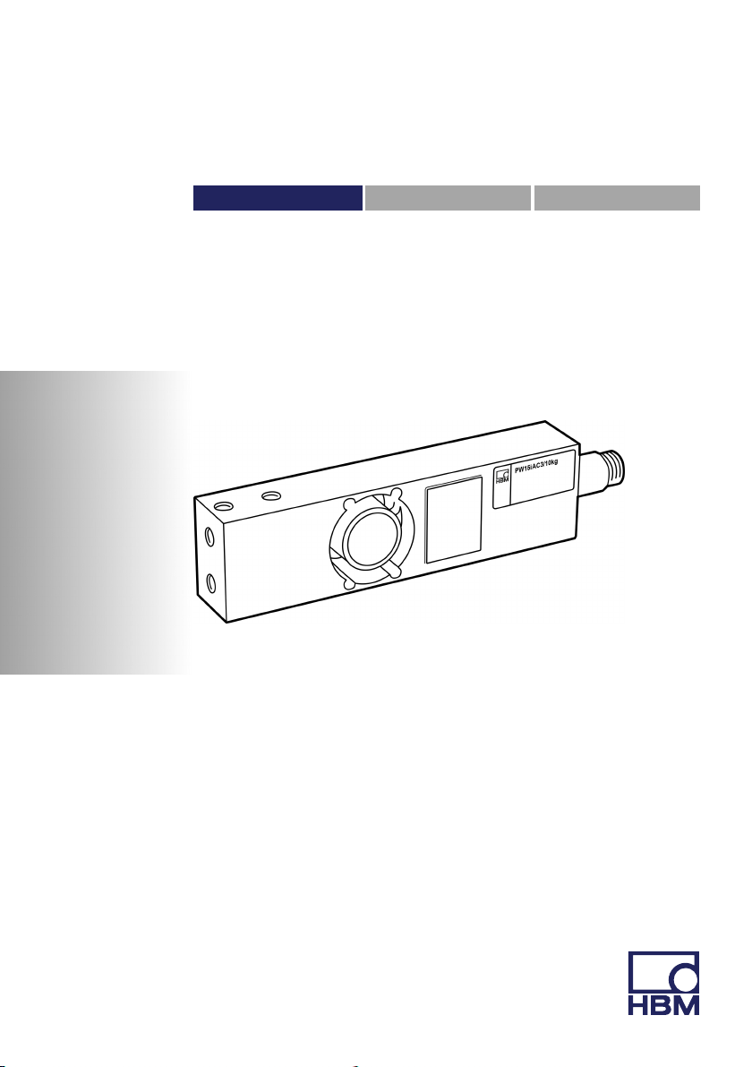
PW15iA
Page 2

Hottinger Baldwin Messtechnik GmbH
Im Tiefen See 45
D-64239 Darmstadt
Tel. +49 6151 803-0
Fax +49 6151 803-9100
info@hbm.com
www.hbm.com
Mat.: 7-2002.4359
DVS: A4359-1.0 HBM: public
1.2016
E Hottinger Baldwin Messtechnik GmbH.
Subject to modifications.
All product descriptions are for general information only.
They are not to be understood as a guarantee of quality or
durability.
Änderungen vorbehalten.
Alle Angaben beschreiben unsere Produkte in allgemeiner
Form. Sie stellen keine Beschaffenheits- oder Haltbarkeits
garantie dar.
Sous réserve de modifications.
Les caractéristiques indiquées ne décrivent nos produits
que sous une forme générale. Elles n'impliquent aucune
garantie de qualité ou de durablilité.
Page 3
Mounting Instructions | Montageanleitung |
Notice de montage
English Deutsch Français
PW15iA
Digital Load Cell
Page 4

English
1 Safety instructions 4........................................
2 Markings used 8............................................
2.1 Symbols on the transducer 8..................................
2.2 The markings used in this document 8..........................
3 Structure and mode of operation 10...........................
3.1 Layout 11....................................................
3.2 Signal conditioning 12.........................................
3.3 Adaptive interference suppression 13............................
3.4 Inputs and outputs 14.........................................
3.4.1 Trigger function 14............................................
3.4.2 Filling and dosing 15..........................................
3.4.3 Limit value function 15.........................................
3.4.4 Extreme value functions 15....................................
4 Conditions on site 16........................................
4.1 Protection against corrosion 16.................................
4.2 Deposits 17..................................................
5 Mechanical installation 18....................................
5.1 Important precautions during installation 18......................
5.2 Mounting and load application 19...............................
5.3 Dimensions 21...............................................
6 Electrical connection 22......................................
6.1 Cable laying 22...............................................
6.2 Pin assignment 22............................................
6.3 Supply voltage 24.............................................
6.4 Digital inputs 25..............................................
6.5 Digital outputs 26.............................................
2 A4359-1.0 HBM: public PW15iA
Page 5

7 Interfaces 27................................................
7.1 RS‐485 4‐wire interfaces (UART) 27............................
7.2 CANopen interface 29.........................................
7.3 DeviceNet interface 30........................................
8 Operation via software 32....................................
9 Waste disposal and environmental protection 32..............
PW15iA A4359-1.0 HBM: public 3
Page 6

Safety instructions
1 Safety instructions
Appropriate use
Transducers of the PW15iA type series are designed
solely for technical weighing applications within the appli
cation limits detailed in the specifications. Any other use
is not appropriate.
Any person instructed to carry out installation, commis
sioning or operation of the transducer must have read
and understood the Operating Manual and in particular
the technical safety instructions.
In the interests of safety, the transducer should only be
operated by qualified personnel and as described in the
Operating Manual. It is also essential to comply with the
legal and safety requirements for the application con
cerned during use. The same applies to the use of
accessories.
The transducer is not intended for use as a safety com
ponent. Please also refer to the "Additional safety pre
cautions" section. Proper and safe operation requires
proper transportation, correct storage, siting and mount
ing, and careful operation.
Operating conditions
S Please observe the allowed maximum values stated
in the specifications for:
- Limit load
- Limit load at max. eccentricity
- Limit lateral loading
- Breaking loads
- Temperature limits
4 A4359-1.0 HBM: public PW15iA
Page 7

Safety instructions
- Limits of electrical loading capacity
S Please note that when several transducers are
installed in a scale, there is not always an even distri
bution of load on the individual transducers.
S The transducers can be used as machine elements.
When used in this manner, it must be noted that, to
favor greater sensitivity, the transducer is not
designed with the safety factors usual in mechanical
engineering.
S The design or safety engineering of the transducer
must not be modified without our express permission.
S The transducer is maintenance-free.
S In accordance with national and local environmental
protection and material recovery and recycling regula
tions, old transducers that can no longer be used
must be disposed of separately and not with normal
household garbage, see Section 9, Page 32.
Qualified personnel
Qualified persons means persons entrusted with the
installation, fitting, commissioning and operation of the
product who possess the appropriate qualifications for
their function.
This includes people who meet at least one of the three
following requirements:
S Knowledge of the safety concepts of measurement
and automation technology is a requirement and as
project personnel, they must be familiar with these
concepts.
S As measurement or automation plant operating per
sonnel, they have been instructed how to handle the
machinery. They are familiar with the operation of the
PW15iA A4359-1.0 HBM: public 5
Page 8

Safety instructions
equipment and technologies described in this docu
mentation.
S As commissioning engineers or service engineers,
they have successfully completed the training to qual
ify them to repair the automation systems. They are
also authorized to activate, ground and label circuits
and equipment in accordance with safety engineering
standards.
Working safely
S The transducer must not be directly connected to the
power supply system. The supply voltage must be
between 12 and 30VDC.
S Error messages should only be acknowledged once
the cause of the error is removed and no further dan
ger exists.
S Maintenance and repair work on an open device with
the power on may only be carried out by trained per
sonnel who are aware of the dangers involved.
S Automation equipment and devices must be designed
in such a way that adequate protection or locking
against unintentional actuation is provided (e.g.
access checks, password protection, etc.).
S For those devices operating in networks, safety pre
cautions must be taken both in terms of hardware and
software, so that a line break or other interruptions to
signal transmission do not cause undefined states or
loss of data in the automation device.
S After making settings and carrying out activities that
are password-protected, ensure that any controls that
may be connected remain in a safe condition until the
switching performance of the device has been tested.
6 A4359-1.0 HBM: public PW15iA
Page 9

Safety instructions
Additional safety precautions
Additional safety precautions to meet the requirements of
the relevant national and local accident prevention regu
lations must be taken in plants where malfunctions could
cause major damage, loss of data or even personal
injury.
The scope of supply and performance of the transducer
covers only a small area of measurement technology.
Before starting up the transducer in a system, a project
planning and risk analysis must first be implemented,
taking into account all the safety aspects of measure
ment and automation technology so that residual risks
are minimized. This particularly concerns personal and
machine protection. The transducers cannot implement
any safety-relevant cutoffs. In the event of a fault, the
relevant precautions must establish safe operating condi
tions.
General dangers of failing to follow the safety
instructions
The transducer corresponds to the state of the art and is
failsafe. The transducer may give rise to residual dangers
if it is inappropriately installed or operated.
PW15iA A4359-1.0 HBM: public 7
Page 10
Markings used
2 Markings used
2.1 Symbols on the transducer
CE mark
The CE mark enables the manufacturer to guarantee that
the product complies with the requirements of the rele
vant EC directives (the Declaration of Conformity can be
found on the HBM website (www.hbm.com) under
HBMdoc).
Statutory waste disposal mark
In accordance with national and local environmental pro
tection and material recovery and recycling regulations,
old devices that can no longer be used must be disposed
of separately and not with normal household garbage.
Also see Section9, Page 32.
2.2 The markings used in this document
Important instructions for your safety are specifically
identified. It is essential to follow these instructions in
order to prevent accidents and damage to property.
Symbol Significance
WARNING
Notice
8 A4359-1.0 HBM: public PW15iA
This marking warns of a potentially dangerous situa
tion in which failure to comply with safety require
ments can result in death or serious physical injury.
This marking draws your attention to a situation in
which failure to comply with safety requirements can
lead to damage to property.
Page 11
Emphasis
See …
Important
Information
Markings used
SignificanceSymbol
This marking draws your attention to important infor
mation about the product or about handling the prod
uct.
This marking draws your attention to information
about the product or about handling the product.
Italics are used to emphasize and highlight text and
identify references to sections, diagrams, or external
documents and files.
PW15iA A4359-1.0 HBM: public 9
Page 12

Structure and mode of operation
3 Structure and mode of operation
PW15iA digital load cells are part of the family of elec
tronics developed by HBM for static and dynamic weigh
ing processes. The measuring element is a steel loaded
member to which strain gages (SG) are applied. The SG
are arranged so that two are stretched and the other two
compressed when a load acts on the load cell. The
PW15iA digitally conditions the signals and delivers a
fully-filtered, scaled and digitized output signal for direct
connection to bus systems or PCs via the RS‐485 inter
face, CANopen, or DeviceNet. Measuring element and
electronics are housed in a single enclosure. The digital
load cells can be quickly and easily matched to a particu
lar system by various parameters, and they work with an
internal data rate of up to 1200 measurements per sec
ond.
The inbuilt digital inputs and outputs allow event-driven
weight determination, e.g. for checkweigher applications
or dosing controls. The digital outputs can be configured
by software command, and can be used to control coarse
flow and fine flow in dosing valves, for example.
The PanelX PC software is available to facilitate parame
ter settings, to display dynamic measurement signals and
for comprehensive frequency analysis of the dynamic
system.
This document describes the installation and functions of
the digital load cell. The commands for the interfaces can
be found in the online documentation for the PanelX pro
gram.
10 A4359-1.0 HBM: public PW15iA
Page 13
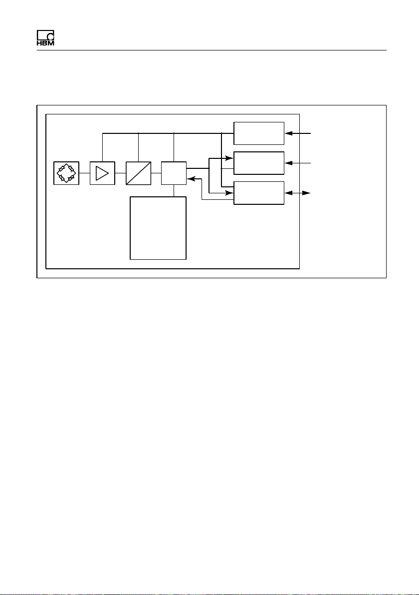
3.1 Layout
Structure and mode of operation
PW15iA
A
D
EEPROM
Linearization
Serial number
Digital filter
Data rate
Sensitivity
Zero value
Voltage
control
Interface
μP
I/Os
Supply
voltage UB/GND
Interface
RS-485/CANopen
IO
Trigger,
Stop Dosing
Fig. 1.1 Block diagram
The analog measuring element signal is amplified, fil
tered, and digitized in the A/D converter. This measure
ment signal is conditioned (filtering, analysis) in the
microprocessor, and transmitted via the interface.
Depending on the configuration, the inputs and outputs
can both control the processing and trigger valves, for
example, subject to the signal. All the parameters can be
stored power failsafe.
The digital load cells have switchable inputs or outputs:
They can use a maximum of 2 inputs or 2 outputs, or one
input and one output.
Detailed information on setting the different functions can
be found in the online help of the PanelX program.
PW15iA A4359-1.0 HBM: public 11
Page 14
Structure and mode of operation
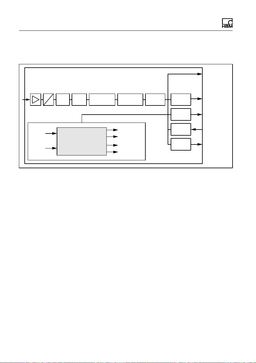
3.2 Signal conditioning
RUN
BRK
FMD
ASF ICR
A
D
Data
Filter Tare
rate
Dosing control
Fig. 1.2 Signal conditioning
Digitization is followed by filtering, using digital filters
adjusted by the software. The ICR command changes
the output rate (measured values per second).
SZA
SFA
Working
standard
calibr.
NOV, RSN
LDW, LWT LIC
User-defined
scaling
Coarse Flow
Fine Flow
Ready
Alarm
Linearization
TAV, TAS
Min/
Max
Trigger
Limit
values
PVA
IMD
LIV
Gross
measured
value
Net
measured
value
Extreme
values
Trigger/
Stop
Limit
values
In the working standard calibration of the electronics (on
delivery), 0 mV/V corresponds to zero and the maximum
capacity is either 1,000,000digits (NOV≠0), or
5,120,000digits (NOV=0). The two parameters LDW and
LWT give you the opportunity to adapt the characteristic
curve to meet your requirements (scale curve) and you
can use the NOV command to standardize the measured
values to the required scaling value (e.g. 3000d).
Detailed information can be found in the command docu
mentation and in the online help for the PanelX program.
You also have the opportunity to
S switch from gross to net signals,
12 A4359-1.0 HBM: public PW15iA
Page 15
Structure and mode of operation
S activate an automatic zero on start up function,
S activate an automatic zero tracking function,
S linearize the scale curve with a third order polynomial,
S activate various digital filters. Available filters include
those with cut-off frequencies below 1Hz, fast-settling
filters for dynamic measurements, notch filters and
mean value filters.
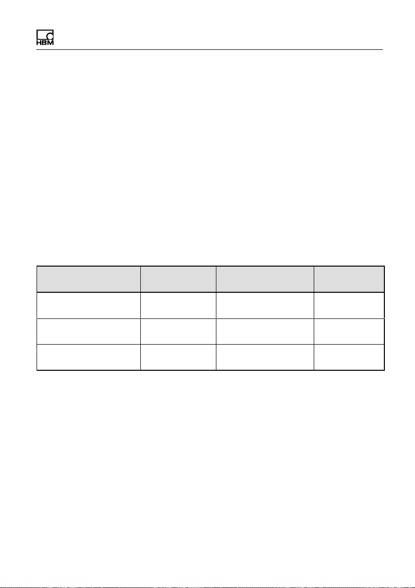
Use MSV? to read out the current measured value. The
format of the measured value (ASCII or binary) is set
with the COF command. You can also use the COF com
mand to activate automatic measurement output. The
measured values are transmitted in the following format,
subject to the COF command:
Output format Input signal Output when NOV=0 Output when
Binary, 2 chars. (INT) 0 … maximum
capacity
Binary, 4 chars. (LONG) 0 … maximum
capacity
ASCII 0 … maximum
capacity
0 … 20,000digits 1 … NOV
0 … 5,120,000digits 1 … NOV
0 … 1,000,000digits 1 … NOV
NOV>0
3.3 Adaptive interference suppression
Whatever the mode of operation, you can use the ADF
command to activate automatic interference suppression
with adaptive filters. Interference frequencies are auto
matically found during measurement and suppressed by
comb filters and averaging. The maximum filter settling
time can be limited with the TMA command.
PW15iA A4359-1.0 HBM: public 13
Page 16

Structure and mode of operation
3.4 Inputs and outputs
The two I/Os can be used either as inputs or outputs.
You can also set different switching levels (TTL or PLC)
for the inputs. On delivery, both I/Os are set as inputs
with a TTL level. Specify the function of the I/Os as
inputs with commands IM1 and IM2, and the function as
outputs with OM1 and OM2.
Notice
The electronics must be operated with a supply voltage
of between 12 and 30V. Incorrect connections between
the supply and interface cables or the digital inputs/out
puts can cause irreversible damage.
So you must check the correct assignment of the con
nections before switching on for the first time.
3.4.1 Trigger function
In Trigger mode (command IMD1), the electronics have
four different trigger functions available:
S Pre-triggering by level
S Pre-triggering by external (digital) signal
S Post-triggering by level
S Post-triggering by external (digital) signal
Gross or net values can be used as input values. The
filter settling time can be optimized by the actual elec
tronics (command AST).
14 A4359-1.0 HBM: public PW15iA
Page 17

Structure and mode of operation
3.4.2 Filling and dosing
The electronics include full dosing control (command
IMD2). As many as 32 parameter sets can be stored in
the EEPROM for different applications. But you can still
change the dosing parameters yourself during dosing.
Digital outputs can be used to control coarse and fine
flow, for example. The PanelX software includes detailed
instructions for setting the different parameters.
3.4.3 Limit value function
In Standard and Trigger modes (command IMD), the
electronics allow as many as four limit values to be moni
tored (command LIV). Gross or net values, the trigger
result, or the extreme values (Min/Max) are available to
you as input signals. Use the measurement status to
read out the status, either simultaneously with the mea
sured values (command MSV?) or separately (command
RIO?).
3.4.4 Extreme value functions
The electronics include a peak value function (Minimum
and Maximum, command PVS), that monitors either the
gross or net values, as required. Use command PVA to
read out the values and use command CPV to reset the
peak values.
PW15iA A4359-1.0 HBM: public 15
Page 18

Structure and mode of operation
4 Conditions on site
Series PW15iA transducers are hermetically encapsu
lated and are therefore very insensitive to the influence of
moisture and humidity. The transducers achieve protec
tion classes IP68 (test conditions: 100 hours under 1m
water column) and IP69K (water at high pressure, steam
cleaning), as per DIN EN60529
transducers must be protected against the lasting effects
of moisture and humidity.
Important
Note that when using a steam cleaner, the conditions
stated in EN 60529 under degree of protection IP69K
such as max. pressure, max. temperature, etc., must be
met.
4.1 Protection against corrosion
1)
. Nevertheless, the
The transducer must be protected against chemicals that
could attack the steel of the housing and base plate, or
the cable.
1)
When connector plug of the same protection class is fitted.
16 A4359-1.0 HBM: public PW15iA
Page 19

Structure and mode of operation
Notice
Acids and all substances that release ions also attack
stainless steels and their seam welds.
The resultant corrosion can cause the transducer to fail.
If this is the case, you must provide appropriate means of
protection.
4.2 Deposits
Dust, dirt and other foreign matter must not be allowed to
accumulate sufficiently to divert some of the measuring
force onto the housing, thus distorting the measured
value (force shunt).
Do not use hard or pointed objects when cleaning the
gap between load application and housing, or between
mounting plate and housing.
PW15iA A4359-1.0 HBM: public 17
Page 20
Structure and mode of operation
5 Mechanical installation
5.1 Important precautions during installation
S Handle the transducer with care.
S Welding currents must not be allowed to flow over the
transducer. If there is a risk that this might happen,
you must provide a suitable low-ohm connection to
electrically bypass the transducer. HBM provides the
highly flexible EEK ground cable for this purpose, for
example. It can be screwed on above and below the
transducer.
S Make sure that the transducer cannot be overloaded.
WARNING
There is a danger of the transducer breaking if it is over
loaded. This can cause danger for the operating person
nel of the system in which the transducer is installed.
Implement appropriate safety measures to avoid over
loads or to protect against the resulting dangers.
Notice
The length of the fastening screws must not exceed the
maximum thread reach of 10mm, as otherwise the trans
ducer could be damaged.
18 A4359-1.0 HBM: public PW15iA
Page 21

Structure and mode of operation
Notice
The transducers are precision measuring elements, and
need to be handled carefully. Dropping or knocking the
transducer may cause permanent damage. Make sure
that the transducer cannot be overloaded, including while
it is being mounted.
5.2 Mounting and load application
Before installing several digital load cells into an installa
tion with a bus system, take the following into account:
S The printed production number (type plate) is required
for setting up data communication. If the type plate
can no longer be seen after installation, the numbers
of each transducer should be noted beforehand. This
enables different addresses to be assigned during
initial operation.
S Alternatively, before connection to the bus system,
you can connect each transducer individually with a
PC, in order to set different addresses (see ADR
command in online help).
Mount the transducer on a clean surface with a flatness
better than 0.1 mm. You can integrate overload protec
tion with an M6x0.5 fine-thread screw.
To minimize off-center load errors and torques, load
should be applied in the center of the platform.
PW15iA A4359-1.0 HBM: public 19
Page 22
Structure and mode of operation
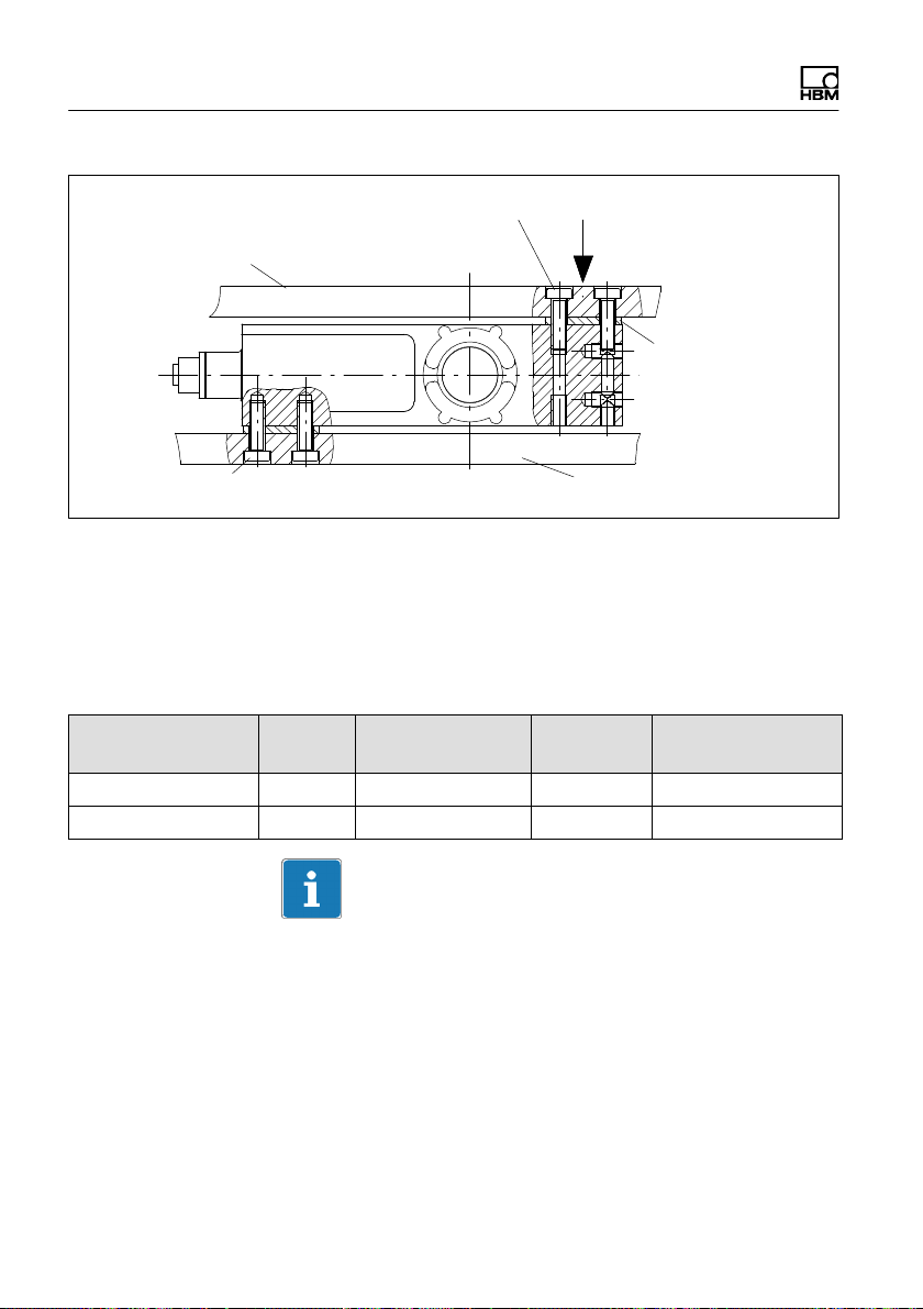
Connection to load application
Platform
(not included in the scope of supply)
Loading direction
Platform center
Load application
(customer construction)
Connection to the mounting plate
(not included in the scope of supply)
Mounting plate
Fig. 3.1 Mounting
Secure the load cell in the mounting holes. A platform for
load application can be mounted on top. The screws and
tightening torques to be used are given in the table
below:
Mounting Thread Min. property
class
On mounting plate M6 10.9 10N @ m 10mm
On load application M6 10.9 10N @ m 10mm
Tightening
torque
Max. thread reach
Important
The unevenness of the surface at the connecting faces
must be no worse than 0.1mm.
20 A4359-1.0 HBM: public PW15iA
Page 23
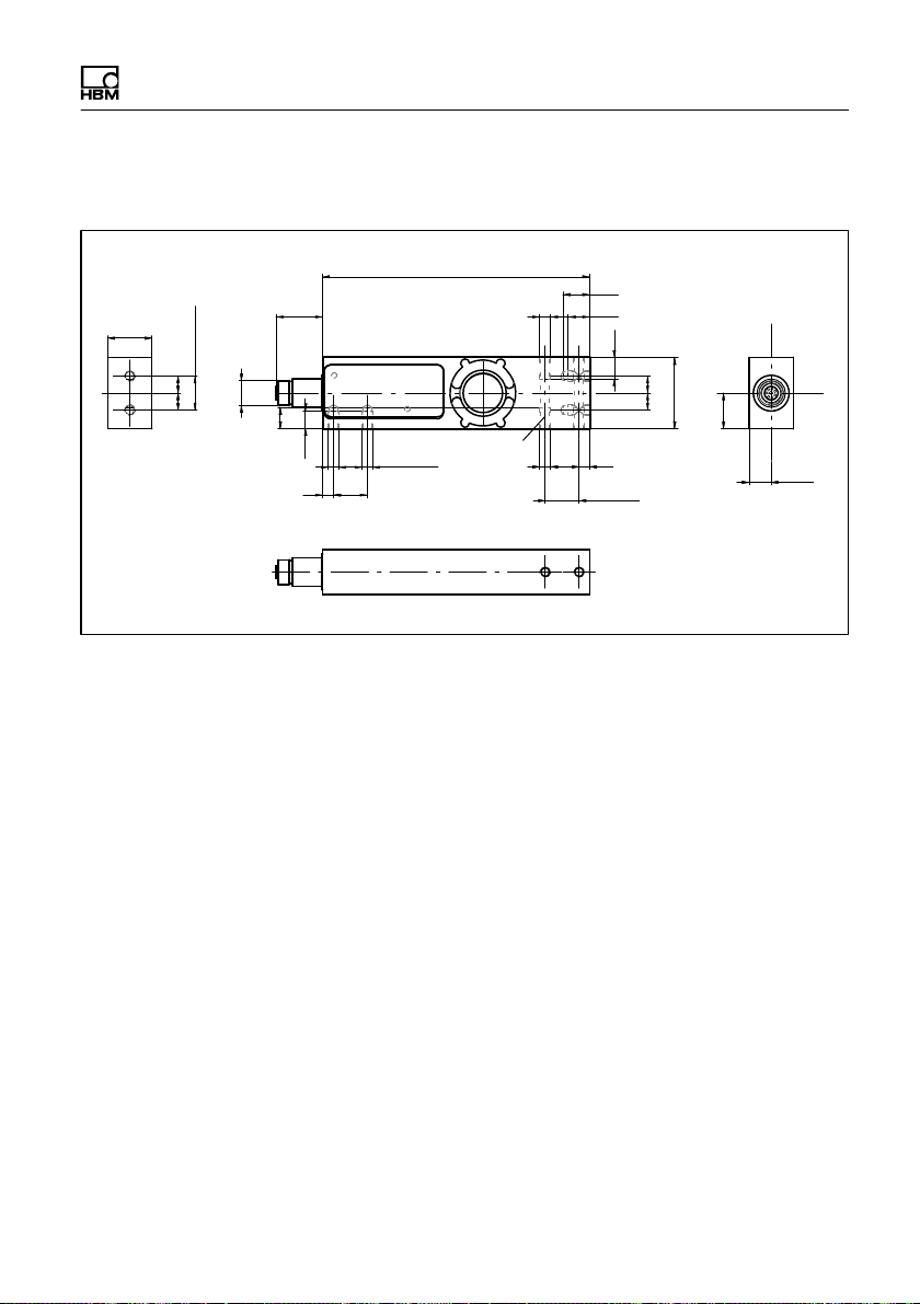
5.3 Dimensions
Structure and mode of operation
25
= =
19.1±0.2
26.2
M14
12
10
19
6
Fig. 3.2 Dimensions
M6 (2x)
150
M6 (6x)
M6x0.5
(1x)
15
12
12
6
19±0.2
= =
40
20
12.5
PW15iA A4359-1.0 HBM: public 21
Page 24

Structure and mode of operation
6 Electrical connection
Notice
Electronic components are sensitive to electrostatic dis
charge (ESD). So you must discharge your own static
electricity before touching the connector plugs.
6.1 Cable laying
Position the connection cable so that any condensation
or moisture that may occur at the cable can drip off
(loop). It must not be allowed to reach the transducer.
Also make sure that it is not possible for humidity or
moisture to get into the cables through open ends, thus
preventing damage to the cable sheath.
6.2 Pin assignment
Notice
The electronics must be operated with a supply voltage
of between 12 and 30V. Incorrect connections between
the supply and interface cables or the digital inputs/out
puts can cause irreversible damage.
So you must check the correct assignment of the con
nections before switching on for the first time.
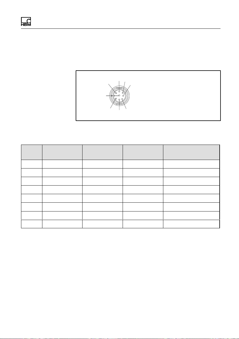
The digital load cell comes supplied with an M12 8‐pin
device socket with internal thread. An M14x1 external
22 A4359-1.0 HBM: public PW15iA
Page 25
Structure and mode of operation
thread for connecting HBM cables 1-173-3-1 or 1-173-6-1
is also available. These cables also have protection class
IP69K.
3
2
8
4
5
1
Fig. 4.1 Connector plug with M12 internal thread, the M14
external thread is not shown here
Pin RS-485 CANopen DeviceNet Color code for con
1 GND GND GND White
2 I/O 2 I/O 2 I/O 2 Brown
3 RA CAN High IN CAN High IN Green
4 I/O 1 I/O 1 I/O 1 Yellow
5 RB CAN Low IN CAN Low IN Gray
6 TB CAN Low OUT CAN Low OUT Pink/black
7 TA CAN High OUT CAN High OUT Blue
8 12 … 30V 12 … 30V 12 … 30V Red
6
7
nection cable
Suitable connection cables can be found in the HBM data
sheet "Cables with a plug", B3644.
Please note:
S The housing of the PW15iA is connected to the cable
shield by the connector socket. To obtain an EMCcompliant connection (EMC = electromagnetic com
patibility), the shield of this cable must be connected
to the housing of the connected device or to ground
PW15iA A4359-1.0 HBM: public 23
Page 26

Structure and mode of operation
potential. A direct, low-ohm contact must be made
with the shield, via EMC-compliant PG cable glands,
for example.
S Should it be necessary, a separate cable can be used
to establish potential equalization between the digital
load cell and the (PC/PLC) master (grounding con
cept). You must not use the cable shield for this
potential equalization.
S Use shielded, low-capacitance cables only for all con
nections (interface, power supply and additional
devices) - (HBM measurement cables meet these
requirements).
S Electrical and magnetic fields often induce interfer
ence voltages in the measurement electronics. Do not
route the measurement cables parallel to power lines
and control circuits. If this is not possible, protect the
measurement cable (with steel conduits, for example).
Avoid stray fields from transformers, motors and con
tact switches.
6.3 Supply voltage
Regulated DC voltage of +12 … +30V is required to
operate the electronics and serial communication.
Voltage source requirements
S The supply voltage must be sufficiently smoothed
(RMS value minus residual ripple > 12 V).
S The electronics have a low-loss controller with a
power consumption of 3 W during operation. The cur
rent consumption is therefore dependent on the level
of the supply voltage:
24 A4359-1.0 HBM: public PW15iA
Page 27

Structure and mode of operation
Power demand in A
S When switched on, the electronics briefly consume a
current of approx. 0.15 A. To ensure a safe start-up,
the power supply must be able to provide this current
without a limit being triggered. This is particularly
important when supplying several PADs from one
power supply. In contrast, the sustained loading is
calculated from the formula shown above.
S Connection to a wide-ranging supply network is not
permitted as this often causes interfering voltage
peaks to be induced. Instead, a local supply must be
provided for the electronics (even when grouped).
S The supply voltage must be insulated from the shield
potential. A connection from GND to the housing is
not required, but the max. potential difference must be
no more than 7 V.
S The supply voltage ground wire (GND) is also used as
the reference potential for the interface signals and
the digital inputs/outputs.
S In layouts with several digital load cells, the supply
can run together with the RS-485 bus lines in a 6-pin
cable (with HBM junction boxes, for example). Ensure
that there is sufficient wire cross-section provided, as
some cable sections will conduct the supply current
for all the connected electronics.
=
3 W
Voltage in V
6.4 Digital inputs
You can select the switching threshold for the digital
inputs with the SPL command. Note the different levels
for High and Low, according to the setting.
PW15iA A4359-1.0 HBM: public 25
Page 28
Structure and mode of operation
SPL0 (default setting) SPL1 (PLC level) Explanation
>4V >10V High level
<1V <6V Low level
GND GND Reference potential
70kΩ 9kΩ Input resistance
6.5 Digital outputs
The following applies for the digital outputs:
Supply voltage +12 ... +30 V
Max. current per output <0.5A
Max. current for all outputs <1A
26 A4359-1.0 HBM: public PW15iA
Page 29

7 Interfaces
Interfaces
The ground reference for all the interface signals is
based on the supply voltage ground (GND). GND (0V) of
the excitation voltage must therefore also be connected,
but you must not connect GND to the shield. Use a sepa
rate line to connect the node digital ground to the power
supply GND (0V).
Use a shielded cable as the interface cable. The shield
should always be connected to the housing at both ends.
Important
Before installing several digital load cells into an installa
tion with a bus system, take the following into account:
The printed production number (type plate) is required for
setting up data communication. If the type plate can no
longer be seen after installation, the numbers of each
digital load cell should be noted beforehand. This enables
different addresses to be assigned during initial opera
tion.
Alternatively, before connection to the bus system, you
can connect each digital load cell individually with a PC,
in order to set different addresses (see ADR command in
the online help).
7.1 RS‐485 4‐wire interfaces (UART)
The PW15iA comes supplied with an RS-485 interface.
Bit rates of 1200 to 115,200 baud can be set for the inter
face.
Either a single digital load cell can be connected via the
RS485 interface, or you can set up a bus system to con
PW15iA A4359-1.0 HBM: public 27
Page 30
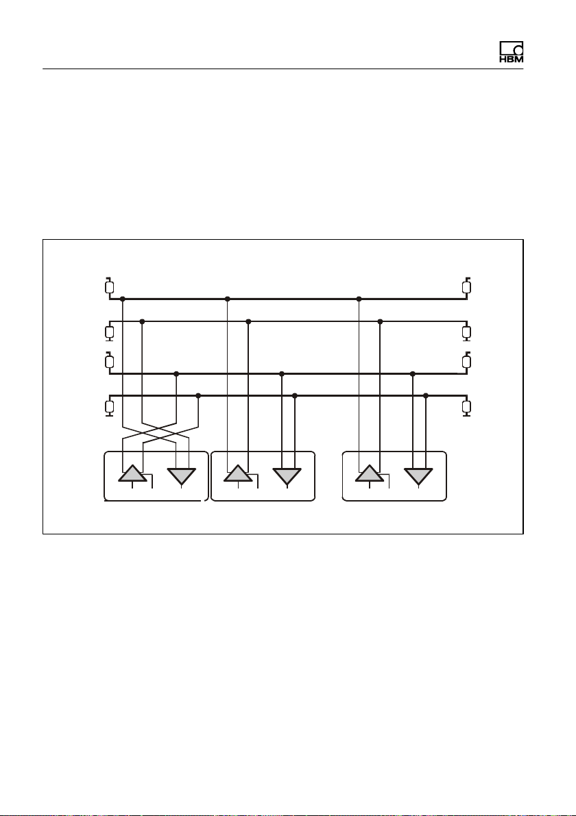
Interfaces
nect as many as 90 digital load cells to an RS-485 inter
face. All the load cells are connected in parallel on a line,
the total length of the line can be as much as 500m. The
software uses the different addresses to differentiate
between the load cells. If the control computer only has
an RS-232 interface, an interface converter is required
(e.g. from HBM, ordering no.: 1-SC232/422B).
Bus termination
+5 V
500 Ω
500 Ω
+5 V
500 Ω
500 Ω
TB TA
T
TxD
PC = Master Node 1 Node 90
Bus termination
500 Ω
500 Ω
500 Ω
500 Ω
RB RA
R
RxD
RB RA
R
on/off
TB
TA
RB
RA
RxD
TB TA
T
on/off
TxD
RB RA
R
RxD
...
TB TA
T
on/off
TxD
Fig. 5.1 Connecting several nodes to a PC via an RS‐485
4‐wire bus
The correct assignment of the transmit and receive lines
can be seen in Fig. 5.1 (bus line Ra to Ta of the con
verter, etc.). The PW15iA already includes bus termina
tion resistors (line termination), that can be activated with
the software command STR. So no additional bus termi
nation resistors are required for RS-485.
+5 V
+5 V
28 A4359-1.0 HBM: public PW15iA
Page 31

Interfaces
7.2 CANopen interface
The interface design follows the CiA DS301 CANopen
standard. The address on delivery is 63.
The CAN bus is set up as a 2‐wire line (CANH and
CANL) (see ISO11898).
Important
You must connect bus termination resistors (each 120W)
at the start and at the end of the bus. The electronics do
not contain a bus termination resistor for CANopen.
Bus termination Bus termination
IN
Master Node 1 Node X
CAN H
CAN L
OUT
Fig. 5.2 CAN bus wiring
IN
OUT
120 W120 W
IN
...
OUT
The bus wiring structure was chosen to minimize the
length of the stub lines. To make wiring simpler, the con
nections for CANH (High) and CANL (Low) are dupli
cated. This means that at a node, you can connect the
lines of the previous one and the lines to the next node to
PW15iA A4359-1.0 HBM: public 29
Page 32

Interfaces
separate connectors. The connectors are linked internally
(bridged), to keep these stub lines as short as possible.
Baud rate and bus cable lengths
The table below gives the maximum cable lengths for
CANopen, subject to the baud rate:
Baud rate in kBits/s 10 20 50 125 250 500 800 1000
Max. cable length inm5000 2500 1000 500 250 100 50 25
The max. cable length is the total line length, calculated
from the length of all the stub lines per node (bus nodes)
and the line length between the nodes. The length of the
stub lines per node is limited, and depends on the baud
rate being used (see CAN bus documentation). In the
electronics, you can set the internal interconnection stub
lines to zero. If you are only using one connection pair
(only CANIN or only CANOUT), the cable length corre
sponds to the stub line length.
Explanations of CANopen communication can also be
found in the online help.
7.3 DeviceNet interface
The DeviceNet interface is based on ISO 11898 and has
been standardized in EN 50325. The hardware is based
on CANopen, so you also need to read through the infor
mation on the CANopen interface. The constraints are
different, however, compared to CANopen. The interface
design follows the DeviceNet specification Release 2.0
ODVA. The load cell address on delivery is 63.
30 A4359-1.0 HBM: public PW15iA
Page 33

Interfaces
Important
You must connect bus termination resistors (each 120W)
at the start and at the end of the bus. The electronics do
not contain a bus termination resistor for DeviceNet.
You should only activate the resistors at the ends of the
bus system. If you activate more than 2 termination resis
tors, or they are not located at the ends, only limited
communication will be possible (bus errors) or it will no
longer work at all.
All the lines refer their level to GND. GND (0V) of the
excitation voltage must therefore also be connected, but
you must not connect GND to the shield. Use a separate
line to connect the node digital ground to the power sup
ply GND (0V). Connect the cable shields extensively to
the connector plug housings.
PW15iA A4359-1.0 HBM: public 31
Page 34

Operation via software
8 Operation via software
When required, download the PanelX software for
parameterization and visualization from the HBM web
site: http://www.hbm.com/software
& AED weighing electronics" area).
("FIT digital load cells
9 Waste disposal and environmental protection
All electrical and electronic products must be disposed of
as hazardous waste. The correct disposal of old equip
ment prevents ecological damage and health hazards.
The electrical and electronic devices that bear this sym
bol are subject to the European waste electrical and elec
tronic equipment directive 2002/96/EC. The symbol indi
cates that, in accordance with national and local
environmental protection and material recovery and recy
cling regulations, old devices that can no longer be used
must be disposed of separately and not with normal
household garbage.
As waste disposal regulations may differ from country to
country, we ask that you contact your supplier to deter
mine what type of disposal or recycling is legally applica
ble in your country.
Packaging
The original HBM packaging is made from recyclable
material and can be sent for recycling. Store the packag
ing for at least the duration of the warranty.
For ecological reasons, empty packaging should not be
returned to us.
32 A4359-1.0 HBM: public PW15iA
Page 35

Mounting Instructions | Montageanleitung |
Notice de montage
English Deutsch Français
PW15iA
Digitale Wägezelle
Page 36

Deutsch
1 Sicherheitshinweise 4......................................
2 Verwendete Kennzeichnungen 8.............................
2.1 Auf dem Aufnehmer angebrachte Symbole 8....................
2.2 In dieser Anleitung verwendete Kennzeichnungen 8..............
3 Aufbau und Wirkungsweise 10...............................
3.1 Aufbau 11...................................................
3.2 Signalverarbeitung 12.........................................
3.3 Adaptive Störunterdrückung 13.................................
3.4 Ein‐ und Ausgänge 14.........................................
3.4.1 Triggerfunktion 14............................................
3.4.2 Füllen und Dosieren 15........................................
3.4.3 Grenzwertfunktion 15..........................................
3.4.4 Extremwertfunktionen 15......................................
4 Bedingungen am Einbauort 16...............................
4.1 Korrosionsschutz 16..........................................
4.2 Ablagerungen 17.............................................
5 Mechanischer Einbau 18.....................................
5.1 Wichtige Vorkehrungen beim Einbau 18.........................
5.2 Montage und Lasteinleitung 19.................................
5.3 Abmessungen 21.............................................
6 Elektrischer Anschluss 22....................................
6.1 Kabelverlegung 22............................................
6.2 Anschlussbelegung 22.........................................
6.3 Versorgungsspannung 24......................................
6.4 Digitale Eingänge 26..........................................
6.5 Digitale Ausgänge 26..........................................
2 A4359-1.0 HBM: public PW15iA
Page 37

7 Schnittstellen 27.............................................
7.1 RS‐485‐4‐Leiter‐Schnittstellen (UART) 27........................
7.2 CANopen‐Schnittstelle 29......................................
7.3 DeviceNet‐Schnittstelle 30.....................................
8 Bedienung über Software 32.................................
9 Entsorgung und Umweltschutz 32............................
PW15iA A4359-1.0 HBM: public 3
Page 38

Sicherheitshinweise
1 Sicherheitshinweise
Bestimmungsgemäße Verwendung
Die Aufnehmer der Typenreihe PW15iA dürfen aus
schließlich für wägetechnische Anwendungen im
Rahmen der durch die technischen Daten spezifizierten
Einsatzgrenzen verwendet werden. Jeder andere Ge
brauch ist nicht bestimmungsgemäß.
Jede Person, die mit Aufstellung, Inbetriebnahme oder
Betrieb des Aufnehmers beauftragt ist, muss die
Bedienungsanleitung und insbesondere die sicherheits
technischen Hinweise gelesen und verstanden haben.
Zur Gewährleistung eines sicheren Betriebes darf der
Aufnehmer nur von qualifiziertem Personal und nach den
Angaben in der Bedienungsanleitung betrieben werden.
Bei der Verwendung sind zusätzlich die für den jeweiligen
Anwendungsfall erforderlichen Rechts‐ und Sicherheits
vorschriften zu beachten. Sinngemäß gilt dies auch bei
der Verwendung von Zubehör.
Der Aufnehmer ist nicht zum Einsatz als Sicherheits
komponente bestimmt. Bitte beachten Sie hierzu den
Abschnitt „Zusätzliche Sicherheitsvorkehrungen“. Der
einwandfreie und sichere Betrieb setzt sachgemäßen
Transport, fachgerechte Lagerung, Aufstellung und
Montage sowie sorgfältige Bedienung voraus.
Betriebsbedingungen
S Beachten Sie insbesondere die in den technischen
Daten angegebenen maximal zulässigen Werte für:
- Grenzlast
- Grenzlast bei max. Exzentrizität
- Grenzquerbelastung
4 A4359-1.0 HBM: public PW15iA
Page 39

Sicherheitshinweise
- Bruchlasten
- Temperaturgrenzen
- Grenzen der elektrischen Belastbarkeit
S Beachten Sie, dass beim Einbau mehrerer Aufnehmer
in eine Waage die Lastverteilung auf die einzelnen
Aufnehmer nicht immer gleichmäßig ist.
S Die Aufnehmer können als Maschinenelemente einge
setzt werden. Beachten Sie bei dieser Verwendung,
dass die Aufnehmer zu Gunsten einer hohen Mess
empfindlichkeit nicht mit den im Maschinenbau übli
chen Sicherheitsfaktoren konstruiert wurden.
S Der Aufnehmer darf ohne unsere ausdrückliche Zu
stimmung weder konstruktiv noch sicherheitstech
nisch verändert werden.
S Der Aufnehmer ist wartungsfrei.
S Nicht mehr gebrauchsfähige Aufnehmer sind gemäß
den nationalen und örtlichen Vorschriften für Umwelt
schutz und Rohstoffrückgewinnung getrennt von regu
lärem Hausmüll zu entsorgen, siehe Abschnitt 9, Seite
32.
Qualifiziertes Personal
Qualifizierte Personen sind Personen, die mit Aufstel
lung, Montage, Inbetriebsetzung und Betrieb des Produk
tes vertraut sind und über die ihrer Tätigkeit entspre
chende Qualifikationen verfügen.
Dazu zählen Personen, die mindestens eine der drei fol
genden Voraussetzungen erfüllen:
S Ihnen sind die Sicherheitskonzepte der Mess‐ und
Automatisierungstechnik bekannt und sie sind als
Projektpersonal damit vertraut.
PW15iA A4359-1.0 HBM: public 5
Page 40

Sicherheitshinweise
S Sie sind Bedienpersonal der Mess‐ oder Automatisie
rungsanlagen und sind im Umgang mit den Anlagen
unterwiesen. Sie sind mit der Bedienung der in dieser
Dokumentation beschriebenen Geräte und Technolo
gien vertraut.
S Sie sind Inbetriebnehmer oder für den Service einge
setzt und haben eine Ausbildung absolviert, die sie
zur Reparatur der Automatisierungsanlagen befähigt.
Außerdem haben sie die Berechtigung, Stromkreise
und Geräte gemäß den Normen der Sicherheitstech
nik in Betrieb zu nehmen, zu erden und zu kennzeich
nen.
Sicherheitsbewußtes Arbeiten
S Der Aufnehmer darf nicht unmittelbar an das Strom
versorgungsnetz angeschlossen werden. Die Versor
gungsspannung darf 12 bis 30VDC betragen.
S Fehlermeldungen dürfen nur quittiert werden, wenn
die Ursache des Fehlers beseitigt ist und keine Ge
fahr mehr existiert.
S Wartungs‐ und Reparaturarbeiten am geöffneten
Gerät unter Spannung dürfen nur von einer ausge
bildeten Person durchgeführt werden, die sich der
vorliegenden Gefahr bewusst ist.
S Geräte und Einrichtungen der Automatisierungstech
nik müssen so verbaut werden, dass sie gegen unbe
absichtigte Betätigung ausreichend geschützt bzw.
verriegelt sind (z.B. Zugangskontrolle, Passwort
schutz o.Ä.).
S Bei Geräten, die in Netzwerken arbeiten, müssen
hard‐ und softwareseitig Sicherheitsvorkehrungen ge
troffen werden, damit ein Leitungsbruch oder andere
Unterbrechungen der Signalübertragung nicht zu un
6 A4359-1.0 HBM: public PW15iA
Page 41

Sicherheitshinweise
definierten Zuständen oder Datenverlust in der Auto
matisierungseinrichtung führen.
S Stellen Sie nach Einstellungen und Tätigkeiten, die
mit Passworten geschützt sind, sicher, dass evtl. an
geschlossene Steuerungen in einem sicheren Zu
stand verbleiben, bis das Schaltverhalten des Gerätes
geprüft ist.
Zusätzliche Sicherheitsvorkehrungen
Bei Anlagen, die aufgrund einer Fehlfunktion größere
Schäden, Datenverlust oder sogar Personenschäden
verursachen können, müssen zusätzliche Sicherheitsvor
kehrungen getroffen werden, die den Anforderungen der
entsprechenden nationalen und örtlichen Unfallverhü
tungsvorschriften genügen.
Der Leistungs‐ und Lieferumfang des Aufnehmers deckt
nur einen Teilbereich der Messtechnik ab. Vor der Inbe
triebnahme des Aufnehmers in einer Anlage ist daher
eine Projektierung und Risikoanalyse vorzunehmen, die
alle Sicherheitsaspekte der Mess‐ und Automatisierungs
technik berücksichtigt, so dass Restgefahren minimiert
werden. Insbesonders betrifft dies den Personen‐ und
Anlagenschutz. Die Aufnehmer können keine sicherheits
relevanten Abschaltungen vornehmen. Im Fehlerfall
müssen entsprechende Vorkehrungen einen sicheren
Betriebszustand herstellen.
Allgemeine Gefahren bei Nichtbeachten der
Sicherheitshinweise
Der Aufnehmer entspricht dem Stand der Technik und ist
betriebssicher. Von dem Aufnehmer können Restgefah
ren ausgehen, wenn er unsachgemäß eingesetzt oder
bedient wird.
PW15iA A4359-1.0 HBM: public 7
Page 42

Verwendete Kennzeichnungen
2 Verwendete Kennzeichnungen
2.1 Auf dem Aufnehmer angebrachte Symbole
CE-Kennzeichnung
Mit der CE‐Kennzeichnung garantiert der Hersteller, dass
sein Produkt den Anforderungen der relevanten
EG‐Richtlinien entspricht (die Konformitätserklärung
finden Sie auf der Website von HBM (www.hbm.com)
unter HBMdoc).
Gesetzlich vorgeschriebene Kennzeichnung zur
Entsorgung
Nicht mehr gebrauchsfähige Altgeräte sind gemäß den
nationalen und örtlichen Vorschriften für Umweltschutz
und Rohstoffrückgewinnung getrennt von regulärem
Hausmüll zu entsorgen. Siehe auch Abschnitt9, Seite
32.
2.2 In dieser Anleitung verwendete Kennzeichnungen
Wichtige Hinweise für Ihre Sicherheit sind besonders ge
kennzeichnet. Beachten Sie diese Hinweise unbedingt,
um Unfälle und Sachschäden zu vermeiden.
8 A4359-1.0 HBM: public PW15iA
Page 43

Symbol Bedeutung
WARNUNG
Hinweis
Wichtig
Diese Kennzeichnung weist auf eine mögliche
gefährliche Situation hin, die – wenn die Sicherheits
bestimmungen nicht beachtet werden – Tod oder
schwere Körperverletzung zur Folge haben kann.
Diese Kennzeichnung weist auf eine Situation hin,
die – wenn die Sicherheitsbestimmungen nicht
beachtet werden – Sachschäden zur Folge haben
kann.
Diese Kennzeichnung weist auf wichtige Informa
tionen zum Produkt oder zur Handhabung des Pro
duktes hin.
Diese Kennzeichnung weist auf Informationen zum
Produkt oder zur Handhabung des Produktes hin.
Information
Hervorhebung
Siehe …
Kursive Schrift kennzeichnet Hervorhebungen im
Text und kennzeichnet Verweise auf Kapitel, Bilder
oder externe Dokumente und Dateien.
Verwendete Kennzeichnungen
PW15iA A4359-1.0 HBM: public 9
Page 44

Aufbau und Wirkungsweise
3 Aufbau und Wirkungsweise
Die digitalen Wägezellen PW15iA gehören zur Familie
der von HBM entwickelten Elektroniken für statische und
dynamische Wägeprozesse. Das Messelement ist ein
Verformungskörper, auf dem Dehnungsmessstreifen
(DMS) angebracht sind. Die DMS sind so angeordnet,
dass zwei von ihnen gedehnt und die zwei anderen
gestaucht werden, wenn auf die Wägezelle eine Last ein
wirkt. Die PW15iA bereitet die Signale digital auf und
liefert ein komplett gefiltertes, skaliertes und digi
talisiertes Ausgangssignal zum direkten Anschluss an
Bussysteme oder PCs über die RS‐485‐Schnittstelle,
CANopen oder DeviceNet. Messelement und Elektronik
sind in einem gemeinsamen Gehäuse untergebracht. Die
digitalen Wägezellen lassen sich über verschiedene
Parameter einfach und schnell an das jeweilige System
anpassen und arbeiten intern mit einer Messrate von bis
zu 1200 Messungen pro Sekunde.
Die eingebauten digitalen Ein-/Ausgänge ermöglichen die
ereignisgesteuerte Gewichtswertbildung, z.B. für Kon
trollwaagen-Anwendungen oder Dosiersteuerungen. Die
per Softwarebefehl konfigurierbaren digitalen Ausgänge
können Sie z.B. zum Steuern von Grobstrom und
Feinstrom bei Dosierventilen verwenden.
Zur einfachen Einstellung aller Parameter, zur Darstel
lung dynamischer Messsignale und zur umfassenden
Frequenzanalyse des dynamischen Systems steht Ihnen
die PC‐Software PanelX zur Verfügung.
Dieses Dokument beschreibt die Montage und die
Funktionen der digitalen Wägezelle. Die Befehle für die
Schnittstellen finden Sie in der Online‐Dokumentation
zum Programm PanelX.
10 A4359-1.0 HBM: public PW15iA
Page 45

3.1 Aufbau
Aufbau und Wirkungsweise
PW15iA
A
D
EEPROM
Linearisierung
Seriennummer
Digitalfilter
Messrate
Empfindlichkeit
Nullwert
Spannungs-
regler
Schnittstelle
μP
I/Os
Versorgungsspannung UB/GND
Schnittstelle
RS-485/CANopen
IO
Trigger,
Stopp Dosieren
Abb. 1.1 Blockschaltbild
Das analoge Signal des Messelements wird verstärkt,
gefiltert und im A/D-Wandler digitalisiert. Dieses Mess
signal wird im Mikroprozessor verarbeitet (Filterung, Aus
wertung) und über die Schnittstelle ausgegeben. Die Einoder Ausgänge können dabei je nach Konfiguration
sowohl die Verarbeitung steuern als auch abhängig vom
Signal die Ansteuerung von z.B. Ventilen vornehmen.
Alle Parameter können netzausfallsicher gespeichert
werden.
Die digitale Wägezelle besitzt umschaltbare Ein- oder
Ausgänge: Sie können maximal 2 Eingänge oder 2 Aus
gänge oder jeweils einen Eingang und einen Ausgang
verwenden.
Detaillierte Angaben zur Einstellung der verschiedenen
Funktionen finden Sie in der Online‐Hilfe des Programms
PanelX.
PW15iA A4359-1.0 HBM: public 11
Page 46

Aufbau und Wirkungsweise
3.2 Signalverarbeitung
FMD
ASF ICR
A
D
RUN
BRK
Mess-
Filter Tarieren
Dosiersteuerung
rate
Werkskali-
brierung
Abb. 1.2 Signalverarbeitung
Nach der Digitalisierung erfolgt die Filterung durch per
Software einstellbare Digitalfilter. Mit dem Befehl ICR
ändern Sie die Ausgaberate (Messwerte pro Sekunde).
SZA
SFA
NOV, RSN
LDW, LWT LIC
Anwenderskalierung
Grobstrom
Feinstrom
Fertig
Alarm
Linearisierung
TAV, TAS
Min/
Max
Trigger
Grenz-
werte
PVA
IMD
LIV
BruttoMesswert
NettoMesswert
Extremwerte
Trigger/
Stopp
Grenzwerte
In der Werkskalibrierung der Elektronik (Auslieferungszu
stand) entspricht 0mV/V Null und die Nennlast entspricht
wahlweise 1.000.000digit (NOV≠0), oder 5.120.000digit
(NOV=0). Sie haben die Möglichkeit, mit dem Parameter
paar LDW und LWT die Kennlinie ihren Anforderungen
(Waagenkennlinie) entsprechend anzupassen und die
Messwerte über den Befehl NOV auf den gewünschten
Skalierungswert (z.B. 3000d) zu normieren. Ausführli
che Angaben finden sie in der Befehlsdokumentation und
in der Onlinehilfe des Programms PanelX.
Sie haben außerdem die Möglichkeit
S von Brutto‐ auf Netto-Signal umzuschalten,
12 A4359-1.0 HBM: public PW15iA
Page 47

Aufbau und Wirkungsweise
S eine automatische Einschalt-Null-Funktion zu
aktivieren,
S eine automatische Zerotracking-Funktion zu
aktivieren,
S eine Linearisierung der Waagenkennlinie mit einem
Polynom 3. Ordnung vorzunehmen,
S verschiedene Digitalfilter zu aktivieren. Es stehen
Filter mit Grenzfrequenzen unter 1Hz und schnell
einschwingende Filter für dynamische Messungen
sowie Notch- und Mittelwertfilter zur Verfügung.
Lesen Sie den aktuellen Messwert über MSV? aus. Das
Format des Messwertes (ASCII oder binär) stellen Sie
über den Befehl COF ein. Sie können auch eine automa
tische Messwertausgabe über den Befehl COF
aktivieren. Die Messwerte werden je nach COF-Befehl in
folgendem Format ausgegeben:
Ausgabeformat Eingangssignal Ausgabe bei NOV=0 Ausgabe bei
NOV>0
Binär 2 Zeichen (INT) 0 … Nennlast 0 … 20.000digit 1 … NOV
Binär 4 Zeichen (LONG) 0 … Nennlast 0 … 5.120.000digit 1 … NOV
ASCII 0 … Nennlast 0 … 1.000.000digit 1 … NOV
3.3 Adaptive Störunterdrückung
Unabhängig vom Betriebsmodus können sie mit dem
Befehl ADF eine automatische Störunterdrückung mit
adaptiven Filtern aktivieren. Dabei werden während der
Messung automatisch Störfrequenzen gesucht und über
Kammfilter und gleitende Mittelwertbildung unterdrückt.
Die maximale Filtereinschwingzeit kann dabei mit dem
Befehl TMA begrenzt werden.
PW15iA A4359-1.0 HBM: public 13
Page 48

Aufbau und Wirkungsweise
3.4 Ein‐ und Ausgänge
Sie können die beiden I/Os sowohl als Eingang als auch
als Ausgang verwenden. Zusätzlich können Sie für die
Eingänge verschiedene Schaltpegel (TTL oder SPS) ein
stellen. Im Auslieferungszustand sind beide I/Os als Ein
gänge mit TTL-Pegel eingestellt. Die Funktion der I/Os
als Eingänge legen Sie mit den Befehlen IM1 und IM2
fest, die Funktion als Ausgänge mit OM1 und OM2.
Hinweis
Die Elektronik muss mit einer Versorgungsspannung zwi
schen 12 und 30V betrieben werden. Unzulässige Ver
bindungen zwischen Versorgungs‐ und Schnittstellen
leitungen oder den digitalen Ein-/Ausgängen können
irreversible Schäden zur Folge haben.
Kontrollieren Sie daher vor dem ersten Einschalten die
korrekte Zuordnung der Anschlüsse.
3.4.1 Triggerfunktion
Die Elektronik verfügt im Betriebsmodus Trigger (Befehl
IMD1) über vier verschiedene Triggerfunktionen:
S Pre-Triggerung über Pegel
S Pre-Triggerung über externes (digitales) Signal
S Post-Triggerung über Pegel
S Post-Triggerung über externes (digitales) Signal
Als Eingangswerte können Sie Brutto- oder Nettowerte
verwenden. Die Filtereinschwingzeit kann von der
Elektronik selbst optimiert werden (Befehl AST).
14 A4359-1.0 HBM: public PW15iA
Page 49

Aufbau und Wirkungsweise
3.4.2 Füllen und Dosieren
Die Elektronik enthält eine komplette Dosiersteuerung
(Befehl IMD2). Dazu lassen sich bis zu 32 Parameter
sätze für unterschiedliche Anwendungen im EEPROM
speichern. Sie können jedoch selbst während des
Dosierens noch Dosierparameter ändern. Die digitalen
Ausgänge können z.B. zur Steuerung von Grob- und
Feinstrom verwendet werden. Die Software PanelX ent
hält eine ausführliche Anleitung zur Einstellung der ver
schiedenen Parameter.
3.4.3 Grenzwertfunktion
Die Elektronik ermöglicht in den Betriebsmodi Standard
und Trigger (Befehl IMD) die Überwachung von bis zu
vier Grenzwerten (Befehl LIV). Als Eingangssignale
stehen Ihnen Brutto‐ oder Nettowert, das Triggerergebnis
oder die Extremwerte (Min/Max) zur Verfügung. Lesen
Sie den Status über den Messwertstatus aus, entweder
gleichzeitig mit Messwerten (Befehl MSV?) oder separat
(Befehl RIO?).
3.4.4 Extremwertfunktionen
Die Elektronik enthält eine Spitzenwertfunktion (Minimum
und Maximum, Befehl PVS), die wahlweise Brutto‐ oder
Nettowerte überwacht. Lesen Sie die Werte über den
Befehl PVA aus und setzen Sie die Spitzenwerte über
den Befehl CPV zurück.
PW15iA A4359-1.0 HBM: public 15
Page 50

Aufbau und Wirkungsweise
4 Bedingungen am Einbauort
Die Aufnehmer der Serie PW15iA sind hermetisch
gekapselt und deshalb sehr unempfindlich gegen
Feuchteeinwirkung. Die Aufnehmer erreichen die Schutz
klassen IP68 (Prüfbedingungen: 100 Stunden unter 1m
Wassersäule) und IP69K (Wasser bei Hochdruck,
Dampfstrahlreinigung) nach DIN EN60529
sollten die Aufnehmer gegen dauerhafte Feuchteeinwir
kung geschützt werden.
Wichtig
Beachten Sie bei einer Reinigung mit Dampfstrahler die
in EN 60529 unter der Schutzart IP69K genannten
Bedingungen wie max. Druck, max. Temperatur usw.
4.1 Korrosionsschutz
1)
. Trotzdem
Der Aufnehmer muss gegen Chemikalien geschützt
werden, die den Stahl des Gehäuses bzw. der Boden
platte oder das Kabel angreifen.
Hinweis
Säuren und alle Stoffe, die Ionen freisetzen, greifen auch
nichtrostende Stähle und deren Schweißnähte an.
Die dadurch auftretende Korrosion kann zum Ausfall des
Aufnehmers führen. Sehen Sie in diesem Fall entspre
chende Schutzmaßnahmen vor.
1)
Bei montiertem Anschlussstecker gleicher Schutzklasse.
16 A4359-1.0 HBM: public PW15iA
Page 51

Aufbau und Wirkungsweise
4.2 Ablagerungen
Staub, Schmutz und andere Fremdkörper dürfen sich
nicht so ansammeln, dass sie einen Teil der Messkraft
auf das Gehäuse umleiten und dadurch den Messwert
verfälschen (Kraftnebenschluss).
Verwenden Sie beim Reinigen des Spalts zwischen Last
einleitung und Gehäuse bzw. Montageplatte und
Gehäuse keine harten oder spitzen Gegenstände.
PW15iA A4359-1.0 HBM: public 17
Page 52

Aufbau und Wirkungsweise
5 Mechanischer Einbau
5.1 Wichtige Vorkehrungen beim Einbau
S Behandeln Sie den Aufnehmer schonend.
S Es dürfen keine Schweißströme über den Aufnehmer
fließen. Sollte diese Gefahr bestehen, so müssen Sie
den Aufnehmer mit einer geeigneten niederohmigen
Verbindung elektrisch überbrücken. Hierzu bietet z.B.
HBM das hochflexible Erdungskabel EEK an, das
oberhalb und unterhalb des Aufnehmers ange
schraubt wird.
S Stellen Sie sicher, dass der Aufnehmer nicht
überlastet werden kann.
WARNUNG
Bei einer Überlastung des Aufnehmers besteht die
Gefahr, dass der Aufnehmer bricht. Dadurch können
Gefahren für das Bedienpersonal der Anlage auftreten, in
die der Aufnehmer eingebaut ist.
Treffen Sie geeignete Sicherungsmaßnahmen zur
Vermeidung einer Überlastung oder zur Sicherung gegen
sich daraus ergebende Gefahren.
Hinweis
Die Länge der Befestigungsschrauben darf die maximale
Einschraublänge von 10mm nicht überschreiten, da
sonst der Aufnehmer beschädigt werden kann.
18 A4359-1.0 HBM: public PW15iA
Page 53

Aufbau und Wirkungsweise
Hinweis
Die Aufnehmer sind Präzisions‐Messelemente und
verlangen daher eine umsichtige Handhabung. Stöße
oder Stürze können zu permanenten Schäden am Auf
nehmer führen. Sorgen Sie dafür, dass auch bei der
Montage keine Überlastung des Aufnehmers auftreten
kann.
5.2 Montage und Lasteinleitung
Beachten Sie vor dem Einbau mehrerer digitaler Wäge
zellen in eine Anlage mit Bussystem:
S Die aufgedruckte Fertigungsnummer (Typenschild)
wird für die Einrichtung der Datenkommunikation
benötigt. Falls das Typenschild nach dem Einbau
nicht mehr zugänglich ist, sollten Sie die Nummern
aller Aufnehmer notieren. Damit ist eine Zuteilung ver
schiedener Adressen bei der ersten Inbetriebnahme
möglich.
S Alternativ können Sie vor dem Anschluss an das Bus
system jeden Aufnehmer einzeln mit einem PC ver
binden, um unterschiedliche Adressen einzustellen
(siehe ADR-Befehl in der Online-Hilfe).
Montieren Sie den Aufnehmer auf einer sauberen Fläche
mit einer Ebenheit von besser als 0,1 mm. Eine Überlast
sicherung können Sie mit einer Feingewindeschraube
M6x0.5 integrieren.
Um Eckenlastfehler und Momente zu minimieren, sollten
Sie die Lasteinleitung in der Mitte der Plattform vorsehen.
PW15iA A4359-1.0 HBM: public 19
Page 54

Aufbau und Wirkungsweise
Befestigung an Lasteinleitung
Plattform
(nicht im Lieferumfang enthalten)
Belastungsrichtung
Mitte Plattform
Lasteinleitung
(Konstruktion
durch Kunden)
Befestigung an Montageplatte
(nicht im Lieferumfang enthalten)
Montageplatte
Abb. 3.1 Montage
Befestigen Sie die Wägezelle an den Montagebohrun
gen. Eine Plattform zur Lasteinleitung kann auf der Ober
seite montiert werden. Die folgende Tabelle enthält die
zu verwendenden Schrauben und Anzugsmomente.
Befestigung Gewinde Min. Festigkeits
klasse
An Montageplatte M6 10.9 10N @ m 10mm
An Lasteinleitung M6 10.9 10N @ m 10mm
Anzugs
moment
Max. Einschraub
tiefe
Wichtig
Die Unebenheit der Oberfläche an den Verbindungsflä
chen darf nicht schlechter als 0,1mm sein.
20 A4359-1.0 HBM: public PW15iA
Page 55

5.3 Abmessungen
Aufbau und Wirkungsweise
25
= =
19,1±0,2
26,2
M14
12
10
6
M6 (2x)
19
Abb. 3.2 Abmessungen
150
M6 (6x)
M6x0.5
(1x)
15
12
12
6
19±0,2
= =
40
20
12,5
PW15iA A4359-1.0 HBM: public 21
Page 56

Aufbau und Wirkungsweise
6 Elektrischer Anschluss
Hinweis
Elektronische Bauteile sind empfindlich gegen elektrosta
tische Aufladung (ESD, Electro‐Static Discharge). Leiten
Sie daher statische Aufladungen von sich ab, bevor Sie
Anschlussstecker berühren.
6.1 Kabelverlegung
Legen Sie Anschlusskabel so, dass eventuell am Kabel
entstandenes Kondenswasser oder Feuchtigkeit
abtropfen kann (Schlaufe). Es darf nicht zum Aufnehmer
hingeleitet werden. Sorgen Sie auch dafür, dass keine
Feuchtigkeit am offenen Kabelende eindringen kann und
eine Beschädigung des Kabelmantels verhindert wird.
6.2 Anschlussbelegung
Hinweis
Die Elektronik muss mit einer Versorgungsspannung zwi
schen 12 und 30V betrieben werden. Unzulässige Ver
bindungen zwischen Versorgungs‐ und Schnittstellen
leitungen oder den digitalen Ein-/Ausgängen können
irreversible Schäden zur Folge haben.
Kontrollieren Sie daher vor dem ersten Einschalten die
korrekte Zuordnung der Anschlüsse.
22 A4359-1.0 HBM: public PW15iA
Page 57

Aufbau und Wirkungsweise
Die digitale Wägezelle wird mit einer 8‐poligen Geräte
buchse M12 mit Innengewinde ausgeliefert. Zusätzlich
steht ein Außengewinde M14x1 zum Anschluss der
Kabel 1-173-3-1 oder 1-173-6-1 von HBM zur Verfügung.
Diese Kabel besitzen ebenfalls die Schutzklasse IP69K.
3
2
8
4
5
1
Abb. 4.1 Anschlussstecker mit M12‐Innengewinde, das
M14-Außengewinde ist hier nicht eingezeichnet
Pin RS-485 CANopen DeviceNet Farbcode für
1 GND GND GND Weiß
2 I/O 2 I/O 2 I/O 2 Braun
3 RA CAN High IN CAN High IN Grün
4 I/O 1 I/O 1 I/O 1 Gelb
5 RB CAN Low IN CAN Low IN Grau
6 TB CAN Low OUT CAN Low OUT Rosa/schwarz
7 TA CAN High OUT CAN High OUT Blau
8 12 … 30V 12 … 30V 12 … 30V Rot
6
7
Anschlusskabel
Geeignete Anschlusskabel finden Sie im Datenblatt
„Kabel mit Stecker“, B3643, von HBM.
Bitte beachten Sie
S Das Gehäuse der PW15iA ist über die Anschluss
buchse mit dem Kabelschirm verbunden. Für einen
EMV‐gerechten Anschluss (EMV = Elektro‐Magne
PW15iA A4359-1.0 HBM: public 23
Page 58

Aufbau und Wirkungsweise
tische Verträglichkeit) muss der Schirm dieses Kabels
mit dem Gehäuse des angeschlossenen Gerätes bzw.
dem Erdpotential verbunden werden. Der Schirm ist
direkt und niederohmig zu kontaktieren, z.B. durch
EMV‐gerechte PG‐Durchführungen.
S Falls die Notwendigkeit besteht, stellen Sie über eine
gesonderte Leitung den Potenzialausgleich zwischen
der digitalen Wägezelle und dem Master (PC/SPS)
her (Erdungskonzept). Für diesen Potenzialausgleich
dürfen Sie nicht den Leitungsschirm verwenden.
S Verwenden Sie für alle Verbindungen (Schnittstelle,
Versorgung und Zusatzeinrichtungen) nur abge
schirmte, kapazitätsarme Kabel (Messkabel von HBM
erfüllen diese Bedingungen).
S Elektrische und magnetische Felder verursachen oft
eine Einkopplung von Störspannungen in die Mess
elektronik. Legen Sie die Messkabel nicht parallel zu
Starkstrom‐ und Steuerleitungen. Falls das nicht mög
lich ist, schützen Sie das Messkabel (z.B. durch
Stahlpanzerrohre). Meiden Sie Streufelder von Trafos,
Motoren und Schützen.
6.3 Versorgungsspannung
Für den Betrieb der Elektronik und der seriellen Kom
munikation wird eine geregelte Gleichspannung von +12
... +30 V benötigt.
Anforderungen an die Spannungsquelle
S Die Versorgungsspannung muss ausreichend geglät
tet sein (Effektivwert abzgl. Restwelligkeit > 12 V).
S Die Elektronik verfügt über einen verlustarmen
Regler, der im Betrieb eine Leistung von 3 W auf
24 A4359-1.0 HBM: public PW15iA
Page 59

Aufbau und Wirkungsweise
nimmt. Die Stromaufnahme ist daher von der Höhe
der Versorgungsspannung abhängig:
Strombedarf in A
S Die Elektronik nimmt im Einschaltmoment kurzzeitig
einen Strom von ca. 0,15 A auf. Um einen sicheren
Anlauf zu gewährleisten, muss die Versorgung diesen
Strom bereitstellen können, ohne dass eine
Begrenzung anspricht. Dies ist insbesondere bei der
Versorgung mehrerer Elektroniken durch ein einziges
Netzteil zu beachten. Die Dauerbelastung ergibt sich
dagegen aus der oben angegebenen Formel.
S Der Anschluss an ein weitläufiges Versorgungsnetz
ist nicht zulässig, weil dadurch oft störende
Spannungsspitzen eingekoppelt werden. Sehen Sie
statt dessen eine lokale Versorgung für die
Elektroniken (auch mehrere gemeinsam) vor.
S Die Versorgungsspannung ist gegenüber dem
Schirmpotenzial isoliert. Eine Verbindung von GND
mit dem Gehäuse ist nicht erforderlich, die Potenzial
differenz darf jedoch maximal 7 V betragen.
S Der Masseleiter der Versorgungsspannung (GND)
dient auch als Bezugspotential für die Schnittstellensi
gnale und die digitalen Ein-/Ausgänge.
=
3 W
Spannung in V
S Bei Aufbauten mit mehreren digitalen Wägezellen
kann die Versorgung gemeinsam mit den
RS‐485‐Busleitungen in einem 6‐poligen Kabel verlegt
werden (z.B. mit HBM‐Klemmenkästen). Achten Sie
dabei auf einen ausreichenden Leiterquerschnitt, da
einige Kabelabschnitte den Versorgungsstrom für alle
angeschlossenen Elektroniken führen.
PW15iA A4359-1.0 HBM: public 25
Page 60

Aufbau und Wirkungsweise
6.4 Digitale Eingänge
Sie können die Schaltschwelle für die digitalen Eingänge
mit dem Befehl SPL umschalten. Beachten Sie je nach
Einstellung die unterschiedlichen Pegel für High and Low.
SPL0 (Voreinstellung) SPL1 (SPS-Pegel) Erläuterung
>4V >10V High-Pegel
<1V <6V Low-Pegel
GND GND Bezugspotenzial
70kΩ 9kΩ Eingangswiderstand
6.5 Digitale Ausgänge
Für die digitalen Ausgänge gilt:
Versorgungsspannung +12 ... +30 V
Max. Strom pro Ausgang <0,5A
Max. Strom für alle Ausgänge <1A
26 A4359-1.0 HBM: public PW15iA
Page 61

7 Schnittstellen
Als Bezugsmasse aller Schnittstellensignale wird die
Masse der Versorgungsspannung verwendet (GND).
GND (0V) der Speisespannung muss deshalb ebenfalls
verbunden werden, Sie dürfen aber GND nicht mit dem
Schirm verbinden. Verwenden Sie eine separate Leitung,
um die digitale Masse der Teilnehmer mit GND (0 V) der
Stromversorgung zu verbinden.
Verwenden Sie für das Schnittstellenkabel eine
geschirmte Leitung. Der Schirm sollte immer an beiden
Enden mit dem Gehäuse verbunden sein.
Beachten Sie vor dem Einbau mehrerer digitalen Wäge
zellen in eine Anlage mit Bussystem:
Die aufgedruckte Fertigungsnummer (Typenschild) wird
für die Einrichtung der Datenkommunikation benötigt.
Falls das Typenschild nach dem Einbau nicht mehr
zugänglich ist, sollten Sie die Nummern aller digitalen
Wägezellen notieren. Damit ist eine Zuteilung verschie
dener Adressen bei der ersten Inbetriebnahme möglich.
Alternativ können Sie vor Anschluss an das Bussystem
jede digitale Wägezelle einzeln mit einem PC verbinden,
um unterschiedliche Adressen einzustellen (siehe
ADR‐Befehl in der Online‐Hilfe).
Schnittstellen
Wichtig
7.1 RS‐485‐4‐Leiter‐Schnittstellen (UART)
Die PW15iA kann mit einer RS‐485‐ Schnittstelle
geliefert werden. Für die Schnittstelle sind Bitraten von
1200 bis 115.200 Baud einstellbar.
PW15iA A4359-1.0 HBM: public 27
Page 62

Schnittstellen
Über die RS-485-Schnittstelle kann entweder eine ein
zelne digitale Wägezelle angeschlossen werden oder Sie
können durch einen Aufbau als Bussystem bis zu 90 digi
tale Wägezellen an eine RS-485‐Schnittstelle
anschließen. Dabei sind alle Wägezellen an einer Leitung
parallel geschaltet, die Gesamtlänge der Leitung darf
dabei bis zu 500m betragen. Die Unterscheidung zwi
schen den Wägezellen erfolgt per Software durch die
unterschiedlichen Adressen. Besitzt der Steuerrechner
nur eine RS‐232‐Schnittstelle, ist ein Schnittstellenkon
verter (z.B. von HBM, Bestell‐Nr.: 1‐SC232/422B)
erforderlich.
Busabschluss
+5 V
500 Ω
500 Ω
+5 V
500 Ω
500 Ω
TB TA
T
TxD
TB
TA
RB
RA
RB RA
R
on/off
PC = Master Teilnehmer 1 Teilnehmer 90
RxD
TB TA
T
on/off
TxD
RB RA
R
RxD
...
TB TA
T
on/off
TxD
RB RA
R
RxD
Abb. 5.1 Anschluss mehrerer Teilnehmer an einen PC über
RS‐485‐4‐Leiter‐Bus
Die richtige Zuordnung von Sende‐ und Empfangslei
tungen ist in Abb. 5.1 dargestellt (Busleitung Ra an Ta
Busabschluss
500 Ω
500 Ω
500 Ω
500 Ω
+5 V
+5 V
28 A4359-1.0 HBM: public PW15iA
Page 63

Schnittstellen
des Konverters etc.). Die PW15iA enthält bereits Bus
abschluss‐Widerstände (Leitungsabschluss), die mit dem
Softwarebefehl STR aktiviert werden können. Zusätzliche
Busabschlusswiderstände sind daher bei RS-485 nicht
notwendig.
7.2 CANopen‐Schnittstelle
Die Schnittstelle ist nach CANopen‐Standard CiA DS301
ausgeführt. Die Adresse bei Auslieferung ist 63.
Der CAN‐Bus ist als 2‐Draht‐Leitung (CANH und CANL)
aufgebaut (siehe ISO11898).
Wichtig
Sie müssen am Anfang und am Ende des Busses Bus
abschluss‐Widerstände (je 120W) anschließen. Die
Elektroniken enthalten keinen Busabschluss‐Widerstand
für CANopen.
Busabschluss Busabschluss
IN
Master Teilnehmer 1 Teilnehmer X
CAN H
CAN L
OUT
Abb. 5.2 Busverdrahtung CAN-Bus
IN
OUT
...
120 W120 W
IN
OUT
PW15iA A4359-1.0 HBM: public 29
Page 64

Schnittstellen
Die Struktur der Busverdrahtung wurde so gewählt, dass
die Länge der Stichleitungen minimiert wird. Um die Ver
drahtung zu vereinfachen, sind die Anschlüsse für
CANH (High) und CANL (Low) doppelt ausgelegt. Sie
können daher an einem Teilnehmer die Leitungen vom
vorherigen und die Leitungen zum nächsten Teilnehmer
an separaten Anschlüssen anschließen. Die Anschlüsse
sind intern verbunden (gebrückt), um diese Stich
leitungen so kurz wie möglich zu halten.
Baudrate und Bus‐Kabellänge
Als maximale Kabellänge in Abhängigkeit von der Bau
drate gilt für CANopen:
Baudrate in kBit/s 10 20 50 125 250 500 800 1000
Max. Kabellänge in m 5000 2500 1000 500 250 100 50 25
Die max. Kabellänge ist die Gesamtleitungslänge, die
sich aus der Länge aller Stichleitungen pro Knoten (Bus
teilnehmer) und der Leitungslänge zwischen den Knoten
errechnet. Die Länge der Stichleitungen pro Knoten ist
begrenzt und von der verwendeten Baudrate abhängig
(siehe CAN-Bus-Dokumentation). Bei den Elektroniken
können Sie die Stichleitungslänge der internen Ver
schaltung zu Null setzen. Falls Sie nur ein Anschlusspaar
verwenden (nur CANIN oder nur CANOUT), entspricht
die Kabellänge der Stichleitungslänge.
Erläuterungen zur CANopen‐Kommunikation finden Sie
auch in der Online‐Hilfe.
7.3 DeviceNet‐Schnittstelle
Die DeviceNet-Schnittstelle basiert auf ISO 11898 und
wurde in EN 50325 standardisiert. Die Hardware basiert
auf CANopen, lesen Sie daher auch die Informationen
30 A4359-1.0 HBM: public PW15iA
Page 65

Schnittstellen
zur CANopen-Schnittstelle durch. Allerdings gibt es ver
schiedene Einschränkungen gegenüber CANopen. Die
Schnittstelle ist nach DeviceNet‐Spezifikation, Release
2.0 ODVA, ausgeführt. Die Adresse der Wägezelle bei
Auslieferung ist 63.
Wichtig
Sie müssen am Anfang und am Ende des Busses Bus
abschluss‐Widerstände (je 120W) anschließen. Die
Elektroniken enthalten keinen Busabschluss‐Widerstand
für DeviceNet.
Sie dürfen die Widerstände nur an den Enden des Bus
systems aktivieren. Falls Sie mehr als 2 Abschlusswider
stände aktivieren oder sich diese nicht an den Enden
befinden, funktioniert die Kommunikation nur einge
schränkt (Busfehler) oder gar nicht mehr.
Alle Leitungen beziehen ihre Pegel auf GND. GND (0V)
der Speisespannung muss deshalb ebenfalls verbunden
werden, Sie dürfen aber GND nicht mit dem Schirm ver
binden. Verwenden Sie eine separate Leitung, um die
digitale Masse der Teilnehmer mit GND (0V) der Strom
versorgung zu verbinden. Verbinden Sie die Kabel
schirme flächig mit den Gehäusen der Anschlussstecker.
PW15iA A4359-1.0 HBM: public 31
Page 66

Bedienung über Software
8 Bedienung über Software
Laden Sie bei Bedarf die Software PanelX zur Parame
trierung und Visualisierung von der Website von HBM
herunter: http://www.hbm.com/software
Digitale Wägezellen & AED Wägeelektroniken“).
9 Entsorgung und Umweltschutz
Alle elektrischen und elektronischen Produkte müssen
als Sondermüll entsorgt werden. Die ordnungsgemäße
Entsorgung von Altgeräten beugt Umweltschäden und
Gesundheitsgefahren vor.
Elektrische und elektronische Geräte, die dieses Symbol
tragen, unterliegen der europäischen Richtlinie
2002/96/EG über elektrische und elektronische Altgeräte.
Das Symbol weist darauf hin, dass nicht mehr
gebrauchsfähige Altgeräte gemäß den europäischen Vor
schriften für Umweltschutz und Rohstoffrückgewinnung
getrennt von regulärem Hausmüll zu entsorgen sind.
(Bereich „FIT
Da die Entsorgungsvorschriften von Land zu Land unter
schiedlich sind, bitten wir Sie, im Bedarfsfall Ihren Liefe
ranten anzusprechen, welche Art von Entsorgung oder
Recycling in Ihrem Land vorgeschrieben ist.
Verpackungen
Die Originalverpackung von HBM besteht aus recycleba
rem Material und kann der Wiederverwertung zugeführt
werden. Bewahren Sie die Verpackung jedoch mindes
tens für den Zeitraum der Gewährleistung auf.
Aus ökologischen Gründen sollte auf den Rücktransport
der leeren Verpackungen an uns verzichtet werden.
32 A4359-1.0 HBM: public PW15iA
Page 67

Mounting Instructions | Montageanleitung |
Notice de montage
English Deutsch Français
PW15iA
Peson numérique
Page 68

Français
1 Consignes de sécurité 4....................................
2 Marquages utilisés 9........................................
2.1 Symboles apposés sur le capteur 9............................
2.2 Marquages utilisés dans le présent document 9..................
3 Structure et principe de fonctionnement 11....................
3.1 Structure 12..................................................
3.2 Traitement de signal 13........................................
3.3 Antiparasitage adaptable 14....................................
3.4 Entrées et sorties 15..........................................
3.4.1 Fonction de trigger 15.........................................
3.4.2 Remplissage et dosage 16.....................................
3.4.3 Fonction de seuils 16..........................................
3.4.4 Fonctions de crêtes 17........................................
4 Conditions environnantes à respecter 18......................
4.1 Protection contre la corrosion 18................................
4.2 Dépôts 19...................................................
5 Montage mécanique 20......................................
5.1 Précautions importantes lors du montage 20.....................
5.2 Montage et application de charge 21............................
5.3 Dimensions 23...............................................
6 Raccordement électrique 24..................................
6.1 Pose des câbles 24...........................................
6.2 Code de raccordement 24.....................................
6.3 Tension d'alimentation 26......................................
6.4 Entrées numériques 28........................................
6.5 Sorties numériques 28.........................................
2 A4359-1.0 HBM: public PW15iA
Page 69

7 Interfaces 29................................................
7.1 Interfaces RS-485 4 fils (UART) 30..............................
7.2 Interface CANopen 31.........................................
7.3 Interface DeviceNet 33........................................
8 Commande par logiciel 34....................................
9 Élimination des déchets et protection de l'environnement 35...
PW15iA A4359-1.0 HBM: public 3
Page 70

Consignes de sécurité
1 Consignes de sécurité
Utilisation conforme
Les capteurs de la série PW15iA ne doivent être utilisés
que pour des applications de pesage dans le cadre des
limites d'utilisation spécifiées dans les caractéristiques
techniques. Toute autre utilisation est considérée comme
non conforme.
Toute personne chargée de l'installation, de la mise en
service ou de l'exploitation du capteur doit impérati
vement avoir lu et compris le manuel d'emploi et
notamment les informations relatives à la sécurité.
Pour garantir un fonctionnement du capteur en toute
sécurité, celui-ci doit uniquement être utilisé par du
personnel qualifié conformément aux instructions du
manuel d'emploi. De plus, il convient, pour chaque cas
particulier, de respecter les règlements et consignes de
sécurité correspondants. Ceci s'applique également à
l'utilisation des accessoires.
Le capteur n'est pas destiné à être mis en œuvre comme
élément de sécurité. Reportez-vous à ce sujet au parag
raphe "Mesures de sécurité supplémentaires". Afin de
garantir un fonctionnement parfait et en toute sécurité, il
convient de veiller à un transport, un stockage, une
installation et un montage appropriés et d'assurer un
maniement scrupuleux.
Conditions de fonctionnement
S Respectez notamment les valeurs maximales
admissibles indiquées dans les caractéristiques
techniques pour :
- la charge limite,
- la charge limite pour l'excentricité maxi.,
4 A4359-1.0 HBM: public PW15iA
Page 71

Consignes de sécurité
- la charge transverse limite,
- les charges de rupture,
- les limites de température,
- les limites de charge électrique.
S En cas de montage de plusieurs capteurs dans une
balance, notez que la charge n'est pas toujours
répartie de façon homogène sur les différents cap
teurs.
S Les capteurs peuvent être utilisés en tant qu'éléments
de machine. Dans ce type d'utilisation, notez que les
capteurs ne peuvent pas présenter les facteurs de
sécurité habituels en construction mécanique car l'ac
cent est mis sur la sensibilité élevée.
S Il est interdit de modifier le capteur sur le plan concep
tuel ou celui de la sécurité sans accord explicite de
notre part.
S Le capteur est sans entretien.
S Les capteurs devenus inutilisables ne doivent pas être
mis au rebut avec les déchets ménagers usuels
conformément aux directives nationales et locales
pour la protection de l'environnement et la valorisation
des matières premières, voir chapitre 9, page 35.
Personnel qualifié
Sont considérées comme personnel qualifié les
personnes familiarisées avec l'installation, le montage, la
mise en service et l'exploitation du produit, et disposant
des qualifications correspondantes.
En font partie les personnes remplissant au moins une
des trois conditions suivantes :
PW15iA A4359-1.0 HBM: public 5
Page 72

Consignes de sécurité
S Elles connaissent les concepts de sécurité de la
S Elles sont opérateurs des installations de mesure ou
S En tant que personnes chargées de la mise en
Travail en toute sécurité
S Le capteur ne doit pas être raccordé directement au
S Les messages d'erreur ne doivent être acquittés
technique de mesure et d'automatisation et les maî
trisent en tant que chargés de projet.
d'automatisation et ont été formées pour pouvoir utili
ser les installations. Elles savent comment utiliser les
appareils et technologies décrits dans le présent
document.
service ou de la maintenance, elles disposent d'une
formation les autorisant à réparer les installations
d'automatisation. Elles sont en outre autorisées à
mettre en service, mettre à la terre et marquer des
circuits électriques et appareils conformément aux
normes de la technique de sécurité.
réseau électrique. La tension d'alimentation peut être
comprise entre 12 et 30V
C.C.
qu'une fois l'origine de l'erreur éliminée et lorsqu'il n'y
a plus de danger.
S Les travaux d'entretien et de réparation sur l'appareil
ouvert sous tension sont réservés à une personne
qualifiée ayant connaissance du risque existant.
S Les appareils et dispositifs d'automatisation doivent
être montés de manière à être soit suffisamment
protégés contre toute activation involontaire, soit
verrouillés (contrôle d'accès, protection par mot de
passe ou autres, par exemple).
S Pour les appareils fonctionnant dans des réseaux,
des mesures de sécurité doivent être prises côté
6 A4359-1.0 HBM: public PW15iA
Page 73

Consignes de sécurité
matériel et côté logiciel, afin d’éviter qu’une rupture de
câble ou d’autres interruptions de la transmission des
signaux n’entraînent des états indéfinis ou la perte de
données sur les dispositifs d'automatisation.
S Après avoir effectué des réglages ou toute autre opé
ration protégée par mots de passe, assurez-vous que
les commandes éventuellement raccordées restent
sûres jusqu'au contrôle du comportement de com
mutation de l'appareil.
Mesures de sécurité supplémentaires
Des mesures de sécurité supplémentaires satisfaisant
aux exigences des directives nationales et locales pour la
prévention des accidents du travail doivent être prises
pour les installations risquant de causer des dommages
plus importants, une perte de données ou même des
préjudices corporels, en cas de dysfonctionnement.
Les performances du capteur et l'étendue de la livraison
ne couvrent qu'une partie des techniques de mesure.
Avant la mise en service du capteur dans une instal
lation, une configuration et une analyse de risque tenant
compte de tous les aspects de sécurité de la technique
de mesure et d'automatisation doivent être réalisées de
façon à minimiser les dangers résiduels. Cela concerne
notamment la protection des personnes et des instal
lations. Les capteurs ne peuvent déclencher aucun arrêt
relatif à la sécurité. En cas d’erreur, des mesures appro
priées doivent permettre d'obtenir un état de fonction
nement sûr.
Risques généraux en cas de non-respect des
consignes de sécurité
Le capteur est conforme au niveau de développement
technologique actuel et présente une parfaite sécurité de
PW15iA A4359-1.0 HBM: public 7
Page 74

Consignes de sécurité
fonctionnement. Le capteur peut présenter des dangers
résiduels s'il est utilisé de manière non conforme.
8 A4359-1.0 HBM: public PW15iA
Page 75

2 Marquages utilisés
2.1 Symboles apposés sur le capteur
Marquage CE
Le marquage CE permet au constructeur de garantir que
son produit est conforme aux exigences des directives
européennes correspondantes (la déclaration de
conformité est disponible sur le site Internet de HBM
(www.hbm.com) sous HBMdoc).
Marquage d'élimination des déchets prescrit par la loi
Les appareils usagés devenus inutilisables ne doivent
pas être mis au rebut avec les déchets ménagers usuels
conformément aux directives nationales et locales pour la
protection de l'environnement et la valorisation des
matières premières. Voir également le paragraphe 9,
page 35.
Marquages utilisés
2.2 Marquages utilisés dans le présent document
Les consignes importantes pour votre sécurité sont
repérées d'une manière particulière. Respectez impérati
vement ces consignes pour éviter tout accident et/ou
dommage matériel.
PW15iA A4359-1.0 HBM: public 9
Page 76

Marquages utilisés
Symbole Signification
AVERTISSEMENT
Note
Important
Information
Mise en valeur
Voir …
Ce marquage signale un risque potentiel qui - si les
dispositions relatives à la sécurité ne sont pas res
pectées - peut avoir pour conséquence de graves
blessures corporelles, voire la mort.
Ce marquage signale une situation qui - si les dispo
sitions relatives à la sécurité ne sont pas respectées peut avoir pour conséquence des dégâts matériels.
Ce marquage signale que des informations
importantes concernant le produit ou sa manipulation
sont fournies.
Ce marquage signale que des informations
concernant le produit ou sa manipulation sont
fournies.
Les caractères en italique mettent le texte en valeur
et signalent des renvois à des chapitres, des illus
trations ou des documents et fichiers externes.
10 A4359-1.0 HBM: public PW15iA
Page 77

Structure et principe de fonctionnement
3 Structure et principe de fonctionnement
Les pesons numériques PW15iA font partie de la gamme
des électroniques développées par HBM pour les
pesages statiques et dynamiques. L'élément de mesure
est un corps de déformation sur lequel sont posées des
jauges d'extensométrie. Les jauges sont disposées de
façon à ce que deux d'entre elles soient allongées et les
deux autres comprimées lorsqu'une charge agit sur le
peson. Le PW15iA traite numériquement les signaux et
fournit un signal de sortie entièrement filtré, mis à
l'échelle et numérisé pour être raccordé directement à
des systèmes de bus ou des PC via l'interface RS‐485,
CANopen ou DeviceNet. L’élément de mesure et l’électr
onique sont regroupés dans un même boîtier. Une adap
tation simple et rapide des pesons numériques au sys
tème concerné est possible grâce à divers paramètres.
Ces pesons fonctionnent en interne avec une vitesse de
mesure allant jusqu'à 1200 mesures par seconde.
Les entrées et sorties numériques intégrées permettent
un calcul pondéré des valeurs, par ex. pour les
applications de balances de contrôle ou les systèmes de
commande de dosage. Vous pouvez utiliser les sorties
numériques configurées par instruction logicielle, par
exemple pour la commande de l'alimentation grossière et
fine de vannes de dosage.
Il est possible de régler simplement tous les paramètres,
de représenter les signaux de mesure dynamiques et
d'effectuer une analyse exhaustive de la fréquence du
système dynamique au moyen du logiciel PC PanelX.
Le présent document décrit le montage et les fonctions
du peson numérique. Les commandes des interfaces
sont indiquées dans la documentation en ligne relative au
logiciel PanelX.
PW15iA A4359-1.0 HBM: public 11
Page 78

Structure et principe de fonctionnement
3.1 Structure
PW15iA
Tension
d'alimentation
UB/GND
Interface
RS-485/CANopen
ES
Trigger,
arrêt du dosage
A
Linéarisation
Numéro de série
Filtre numérique
Vitesse de mesure
Sensibilité
Valeur de mise à zéro
N
EEPROM
μP
Régulateur
de tension
Interface
E/S
Fig. 1.1 Synoptique
Le signal analogique de l’élément de mesure est amplifié,
filtré, puis numérisé dans le convertisseur A/N. Ce signal
de mesure est ensuite traité dans le microprocesseur
(filtrage, analyse) et édité via l’interface. Selon la
configuration, les entrées ou sorties peuvent alors com
mander le traitement, mais aussi piloter par exemple des
vannes en fonction du signal. Tous les paramètres
peuvent être enregistrés protégés contre les coupures
secteur.
Le peson numérique possède des entrées et sorties
commutables: vous pouvez utiliser 2 entrées ou 2
sorties maximum, ou encore une entrée et une sortie.
Vous trouverez des indications détaillées sur le réglage
des diverses fonctions dans l’aide en ligne du logiciel
PanelX.
12 A4359-1.0 HBM: public PW15iA
Page 79

RUN
BRK
Structure et principe de fonctionnement
3.2 Traitement de signal
FMD
ASF ICR
A
N
Vit.
Filtre Tarage
de mes.
Contrôle de dosage
Fig. 1.2 Traitement de signal
À l'issue de la numérisation, le filtrage est réalisé par le
filtre numérique configurable par logiciel. Vous pouvez
aussi modifier la vitesse de mesure (valeurs de mesure
par seconde) à l'aide de la commande ICR.
SZA
SFA
Étalonnage
d'usine
NOV, RSN
LDW, LWT LIC
Ajustage
utilisateur
Alim. grossière
Alim. fine
Alarme
d'achèvement
Linéarisation
TAV, TAS
Min/
Max
Trigger
Valeurs
limites
PVA
IMD
LIV
Valeur de
mesure
brute
Valeur de
mesure
nette
Valeurs
crêtes
Trigger/
arrêt
Valeurs
limites
Au niveau de l'étalonnage d'usine de l'électronique (état
à la livraison), 0mV/V correspond à zéro et la portée
maximale correspond au choix à 1000000 digits
(NOV≠0), ou 5120000 digits (NOV=0). Les deux para
mètres LDW et LWT permettent d'adapter la caracté
ristique à vos exigences (caractéristique de pesage). La
commande NOV permet en outre de normaliser les
valeurs de mesure sur la valeur d'ajustage souhaitée (par
ex. 3000 d). Des informations détaillées sont disponibles
dans la documentation de commande et dans l'aide en
ligne du logiciel PanelX.
PW15iA A4359-1.0 HBM: public 13
Page 80

Structure et principe de fonctionnement
En complément, vous pouvez
S passer du signal brut au signal net,
S activer une fonction automatique de zéro d'enclenc
hement,
S activer une fonction automatique de maintien du zéro,
S réaliser une linéarisation de la caractéristique de
pesage via un polynôme de troisième degré,
S activer divers filtres numériques. Des filtres à
fréquences de coupure inférieures à 1Hz et des filtres
à réponse rapide pour les mesures dynamiques ainsi
que des filtres notch et à valeurs moyennes sont
disponibles.
Lisez la valeur de mesure actuelle via MSV?. Vous
réglez le format de la valeur de mesure (ASCII ou
binaire) via la commande COF. Vous pouvez aussi acti
ver une sortie automatique de la valeur de mesure via la
commande COF. Les valeurs de mesure sortent dans les
formats suivants en fonction de la commande COF :
Format de sortie Signal d'entrée Sortie pour NOV=0 Sortie pour
NOV>0
Binaire 2 chiffres (INT) 0 … portée
maximale
Binaire 4 chiffres
(LONG)
ASCII 0 … portée
0 … portée
maximale
maximale
0 … 20000digits 1 … NOV
0 … 5120000digits 1 … NOV
0 … 1000000digits 1 … NOV
3.3 Antiparasitage adaptable
Indépendamment du mode de fonctionnement, la com
mande ADF vous permet d'activer un antiparasitage
14 A4359-1.0 HBM: public PW15iA
Page 81

Structure et principe de fonctionnement
automatique avec des filtres adaptables. Lors de l'opé
ration, des fréquences perturbatrices sont supprimées
automatiquement pendant la mesure à l'aide de filtres en
peigne et du calcul de moyenne glissante. Dans ce
cadre, la durée maximale de réponse du filtre peut être
limitée à l'aide de la commande TMA.
3.4 Entrées et sorties
Vous pouvez utiliser les deux E/S tant comme entrée que
comme sortie. En complément, vous pouvez, pour les
entrées, régler différents niveaux de commutation (TTL
ou API). À la livraison, les deux E/S sont réglées en tant
qu'entrées à niveau TTL. Les commandes IM1 et IM2
vous permettent de définir le fonctionnement des E/S en
tant qu'entrées et les commandes OM1 et OM2 leur
fonctionnement en tant que sorties.
Note
L'électronique doit fonctionner avec une tension d'alimen
tation comprise entre 12 et 30V. Tout raccordement
incorrect de l'alimentation et des câbles d'interface ou
des entrées/sorties numériques peut provoquer des dom
mages irréparables.
Vérifiez donc que les raccordements sont corrects avant
la première mise en marche.
3.4.1 Fonction de trigger
L'électronique prévoit un mode de fonctionnement Trig
ger (commande IMD1) avec quatre fonctions déclenc
heuses différentes :
PW15iA A4359-1.0 HBM: public 15
Page 82

Structure et principe de fonctionnement
S Pré-déclenchement par le niveau
S Pré-déclenchement par signal (numérique) externe
S Post-déclenchement par le niveau
S Post-déclenchement par signal (numérique) externe
Vous pouvez utiliser des valeurs nettes ou brutes en tant
que valeurs d'entrée. Le temps de réponse du filtre peut
être optimisé par l'électronique elle-même (commande
AST).
3.4.2 Remplissage et dosage
L'électronique comporte une commande complète de
dosage (commande IMD2). À cet effet, jusqu’à 32 blocs
de paramètres destinés à des applications différentes
peuvent être enregistrés dans l'EEPROM. Toutefois,
vous pouvez encore modifier des paramètres de dosage
même pendant le dosage. Les sorties numériques
peuvent par ex. être utilisées pour la commande de l'ali
mentation grossière et fine. Le logiciel PanelX comporte
des instructions détaillées concernant le réglage des
divers paramètres.
3.4.3 Fonction de seuils
L'électronique permet, dans les modes de fonction
nement standard et Trigger (commande IMD), la surveil
lance d'un maximum de quatre valeurs limites (com
mande LIV). En tant que signaux d'entrée, vous disposez
de la valeur nette, de la valeur brute, du résultat du
déclenchement ou des valeurs crêtes (Min/Max). Lisez
l'état par le biais de l'état de la valeur de mesure, soit en
même temps que les valeurs de mesure (commande
MSV?) soit séparément (commande RIO?).
16 A4359-1.0 HBM: public PW15iA
Page 83

Structure et principe de fonctionnement
3.4.4 Fonctions de crêtes
L'électronique intègre une fonction de crête (minimum et
maximum, commande PVS), surveillant au choix les
valeurs brutes ou nettes. Lisez les valeurs via la com
mande PVA et réinitialisez les crêtes via la commande
CPV.
PW15iA A4359-1.0 HBM: public 17
Page 84

Structure et principe de fonctionnement
4 Conditions environnantes à respecter
Les capteurs de la série PW15iA sont fermés her
métiquement et sont donc particulièrement insensibles à
l'humidité. Les capteurs atteignent les classes de protec
tion IP68 (conditions d'essai : 100 heures sous une
colonne d'eau de 1m) et IP69K (eau à haute pression,
nettoyage au jet de vapeur) selon DIN EN 60529
capteurs doivent toutefois être protégés contre une pré
sence permanente d'humidité.
Important
Veillez, lors d'un nettoyage au jet de vapeur, à respecter
les conditions, telles que la pression maximale, la
température maximale, etc., citées au niveau de l'indice
de protection IP69K dans la norme EN 60529.
4.1 Protection contre la corrosion
1)
. Les
Le capteur doit être protégé contre les produits chi
miques susceptibles d'attaquer l'acier du boîtier ou de la
plaque de base, ou encore le câble.
1)
Avec un connecteur monté de même classe de protection.
18 A4359-1.0 HBM: public PW15iA
Page 85

Structure et principe de fonctionnement
Note
Les acides et toutes les substances libérant des ions
attaquent également les aciers inoxydables et leurs
cordons de soudure.
La corrosion qui en résulte est susceptible d'entraîner la
défaillance du capteur. Dans ce cas, il faut prévoir des
mesures de protection appropriées.
4.2 Dépôts
La poussière, la saleté et autres corps étrangers ne
doivent pas s'accumuler sous peine de dévier une partie
de la force de mesure sur le boîtier et ainsi de fausser la
valeur de mesure (shunt).
Pour nettoyer l'espace entre l’application de charge et le
boîtier, resp. entre la plaque de montage et le boîtier,
n’utilisez pas d'objets durs ou pointus.
PW15iA A4359-1.0 HBM: public 19
Page 86

Structure et principe de fonctionnement
5 Montage mécanique
5.1 Précautions importantes lors du montage
S Manipulez le capteur avec précaution.
S Aucun courant de soudage ne doit traverser le cap
teur. Si cela risque de se produire, le capteur doit être
shunté électriquement à l'aide d'une liaison de basse
impédance appropriée. À cet effet, HBM propose
parex. le câble de mise à la terre très souple EEK
vissé au-dessus et au-dessous du capteur.
S Assurez-vous que le capteur ne peut pas être sur
chargé.
AVERTISSEMENT
En cas de surcharge du capteur, ce dernier risque de se
briser. Cela peut être dangereux pour les opérateurs de
l'installation dans laquelle le capteur est monté.
Prendre des mesures de protection appropriées pour
éviter toute surcharge ou pour se protéger des risques
qui pourraient en découler.
Note
La longueur des vis de fixation ne doit pas dépasser la
longueur de filet maximale de 10mm afin de ne pas
endommager le capteur.
20 A4359-1.0 HBM: public PW15iA
Page 87

Structure et principe de fonctionnement
Note
Les capteurs sont des éléments sensibles de précision et
doivent donc être maniés avec précaution. Les chocs et
les chutes risquent de provoquer un endommagement
irréversible du capteur. Veillez à ce que le capteur ne
puisse pas être surchargé lors du montage également.
5.2 Montage et application de charge
Avant de monter plusieurs pesons numériques dans une
installation dotée d'un système de bus, tenez compte des
points suivants :
S Le numéro de fabrication (figurant sur la plaque signa
létique) est requis pour la communication de données.
Si la plaque signalétique n'est plus accessible à
l'issue du montage, il est conseillé de noter au préa
lable les numéros de tous les capteurs. Il est ainsi
possible d'affecter des adresses différentes lors de la
première mise en service.
S Vous pouvez également connecter les capteurs un
par un à un PC avant de les raccorder au système de
bus afin de régler des adresses différentes (voir la
commande ADR dans l'aide en ligne).
Montez le capteur sur une surface propre d'une planéité
supérieure à 0,1 mm. Une protection contre les sur
charges peut être intégrée sous forme de vis à filetage
fin M6x0,5.
Pour réduire les erreurs d'excentricité et les couples à un
minimum, il est conseillé de prévoir l’application de
charge au milieu de la plateforme.
PW15iA A4359-1.0 HBM: public 21
Page 88

Structure et principe de fonctionnement
Fixation à l’application de charge
(ne faisant pas partie de la livraison)
Plateforme
Milieu de
la plateforme
Direction de charge
Application de
charge
(construction par
le client)
Fixation sur la plaque de montage
(ne faisant pas partie de la livraison)
Fig. 3.1 Montage
Fixez le peson au niveau des orifices de montage. Il est
possible de monter une plateforme sur le dessus pour
l'application de charge. Le tableau ci-dessous indique les
vis et couples de serrage à utiliser.
Fixation Filetage Classe de dureté
mini.
Sur plaque de
M6 10.9 10N @ m 10mm
montage
Sur application de
M6 10.9 10N @ m 10mm
charge
Important
L’irrégularité de surface des surfaces de jonction ne doit
pas dépasser 0,1mm.
Plaque de montage
Couple de
serrage
Longueur de filet
maxi.
22 A4359-1.0 HBM: public PW15iA
Page 89

Structure et principe de fonctionnement
5.3 Dimensions
25
= =
19,1±0,2
26,2
M14
12
10
19
6
Fig. 3.2 Dimensions
M6 (2x)
150
M6 (6x)
M6x0,5
(1x)
15
12
12
6
19±0,2
= =
40
20
12,5
PW15iA A4359-1.0 HBM: public 23
Page 90

Structure et principe de fonctionnement
6 Raccordement électrique
Note
Les composants électroniques sont sensibles aux
décharges électrostatiques (ESD : Electro‐Static Disc
harge). Éliminez donc l'électricité statique qui est sur
vous avant de toucher des connecteurs.
6.1 Pose des câbles
Posez les câbles de liaison de sorte que d'éventuels
condensats ou l'humidité se formant sur le câble puisse
s'égoutter (boucle). L'eau ne doit pas s'écouler vers le
capteur. Veillez à ce qu'aucune humidité ne puisse
pénétrer à l'extrémité ouverte du câble et à éviter
l'endommagement de la gaine du câble.
6.2 Code de raccordement
Note
L'électronique doit fonctionner avec une tension d'alimen
tation comprise entre 12 et 30V. Tout raccordement
incorrect de l'alimentation et des câbles d'interface ou
des entrées/sorties numériques peut provoquer des dom
mages irréparables.
Vérifiez donc que les raccordements sont corrects avant
la première mise en marche.
24 A4359-1.0 HBM: public PW15iA
Page 91

Structure et principe de fonctionnement
Le peson numérique est livré avec une embase femelle à
8 pôles M12 avec taraudage. Un filetage extérieur M14x1
est également disponible pour raccorder des câbles
1-173-3-1 ou 1-173-6-1 de HBM. Ces câbles possèdent
également la classe de protection IP69K.
3
2
8
4
5
1
Fig. 4.1 Connecteur avec taraudage M12, le filetage
extérieur M14 n’est pas représenté ici
Broche RS-485 CANopen DeviceNet Code couleur câble
1 GND GND GND Blanc
2 I/O 2 I/O 2 I/O 2 Marron
3 RA CAN High IN CAN High IN Vert
4 I/O 1 I/O 1 I/O 1 Jaune
5 RB CAN Low IN CAN Low IN Gris
6 TB CAN Low OUT CAN Low OUT Rose/Noir
7 TA CAN High OUT CAN High OUT Bleu
8 12 … 30V 12 … 30V 12 … 30V Rouge
6
7
de liaison
Les câbles de liaison appropriés sont indiqués dans les
caractéristiques techniques «Câbles avec connecteur»,
B3645, de HBM.
Notez ce qui suit:
S Le boîtier du PW15iA est relié au blindage du câble
via l'embase. Pour obtenir une connexion compatible
PW15iA A4359-1.0 HBM: public 25
Page 92

Structure et principe de fonctionnement
CEM (CEM =compatibilité électromagnétique), le blin
dage de ce câble doit être relié à la terre ou au boîtier
de l'appareil raccordé. Le blindage doit être connecté
directement et à faible impédance, par ex. passages
de câbles PG compatibles CEM.
S Si nécessaire, établissez l'équipotentialité entre le
peson numérique et le maître (PC/API) au moyen
d'une ligne séparée (concept de mise à la terre). Vous
ne devez pas utiliser le blindage du câble pour cette
équipotentialité.
S Pour toutes les connexions (interface, alimentation et
appareils supplémentaires), utilisez uniquement des
câbles blindés de faible capacité (les câbles de
mesure HBM satisfont à ces conditions).
S Les champs électriques et magnétiques provoquent
souvent le couplage de tensions parasites dans
l'électronique de mesure. Évitez absolument de poser
les câbles de mesure en parallèle avec des lignes de
puissance et de contrôle. Si cela n'est pas possible,
protégez le câble de mesure (par ex. à l'aide de tubes
d'acier blindés). Évitez les champs de dispersion des
transformateurs, moteurs et vannes.
6.3 Tension d'alimentation
L'électronique et la communication série nécessitent une
tension d'alimentation continue régulée de +12 à +30 V.
Conditions requises pour la source de tension
S La tension d'alimentation doit être suffisamment lissée
(valeur efficace moins l'ondulation résiduelle > 12 V).
S L'électronique dispose d'un régulateur à faibles pertes
consommant une puissance de 3 W en fonction
26 A4359-1.0 HBM: public PW15iA
Page 93

Structure et principe de fonctionnement
nement. La consommation de courant dépend donc
de la grandeur de la tension d'alimentation:
Courant requis en A
S Lors de la mise en marche, l'électronique requiert
brièvement un courant d'env. 0,15 A. Pour garantir
une mise en marche sûre, l'alimentation doit pouvoir
fournir ce courant, sans générer de limitation. Ce
critère est particulièrement important si plusieurs
électroniques sont alimentées par un même bloc d'ali
mentation secteur. La charge permanente se calcule
en revanche à partir de la formule indiquée plus haut.
S Tout raccordement à un réseau d'alimentation étendu
est interdit, car cela sous-entend souvent le couplage
de crêtes de tension parasites. Au lieu de cela,
prévoyez une alimentation locale pour les élect
roniques (même plusieurs ensemble).
S La tension d'alimentation est isolée du potentiel de
blindage. Il n'est pas nécessaire de relier GND au boî
tier, mais la différence de potentiel ne doit toutefois
pas dépasser 7 V.
S Le fil de terre de la tension d'alimentation (GND) sert
également de potentiel de référence pour les signaux
d'interface et les entrées/sorties numériques.
=
3 W
Tension en V
S En cas de montages comportant plusieurs pesons
numériques, il est possible de regrouper l'alimentation
et les lignes de bus RS-485 dans un câble à 6 pôles
(par ex. avec un boîtier de raccordement de HBM).
Veillez dans ce cadre à ce que la section des fils soit
suffisante, certaines portions du câble devant amener
le courant d'alimentation à toutes les électroniques
raccordées.
PW15iA A4359-1.0 HBM: public 27
Page 94

Structure et principe de fonctionnement
6.4 Entrées numériques
Vous pouvez commuter le niveau de commutation des
entrées numériques via la commande SPL. Notez les
différents niveaux pour High (haut) et Low (bas) en
fonction du réglage.
SPL0 (préréglage) SPL1 (niveau API) Explication
>4V >10V Niveau Haut
<1V <6V Niveau Bas
GND GND Potentiel de référence
70kΩ 9kΩ Résistance d'entrée
6.5 Sorties numériques
Pour les sorties numériques, on a:
Tension d'alimentation +12 ... +30 V
Courant maxi. par sortie <0,5A
Courant maxi. pour toutes les
sorties
<1A
28 A4359-1.0 HBM: public PW15iA
Page 95

7 Interfaces
Interfaces
La masse de référence de tous les signaux d’interface
est la masse de l'alimentation (GND). C’est pourquoi le
GND (0V) de la tension d'alimentation doit être éga
lement relié, mais vous ne devez pas le relier avec le
blindage. Utilisez une ligne séparée pour relier la masse
numérique des nœuds avec le GND (0 V) de l’aliment
ation électrique.
Utilisez un câble blindé en tant que câble d'interface. Les
deux extrémités de ce blindage doivent toujours être rac
cordées au boîtier.
Important
Avant de monter plusieurs pesons numériques dans une
installation dotée d'un système de bus, tenez compte des
points suivants :
Le numéro de fabrication (figurant sur la plaque signa
létique) est requis pour la communication de données. Si
la plaque signalétique n'est plus accessible à l'issue du
montage, il est conseillé de noter au préalable les numé
ros de tous les pesons numériques. Il est ainsi possible
d'affecter des adresses différentes lors de la première
mise en service.
Vous pouvez également connecter les pesons numé
riques un par un à un PC avant de les raccorder au sys
tème de bus afin de régler des adresses différentes (voir
la commande ADR dans l'aide en ligne).
PW15iA A4359-1.0 HBM: public 29
Page 96

Interfaces
7.1 Interfaces RS-485 4 fils (UART)
Le PW15iA peut être livré avec une interface RS-485. Il
est possible de régler des débits de 1200 à 115200
bauds pour l'interface.
L'interface RS-485 permet de raccorder un seul peson
numérique. Vous pouvez également connecter jusqu'à 90
pesons numériques à une interface RS-485 en créant un
système de bus. Lors de l'opération, tous les pesons
sont branchés en parallèle à une ligne, la longueur totale
de la ligne ne doit pas dépasser 500m. La distinction
entre les pesons est réalisée par logiciel grâce aux dif
férentes adresses. Si l'ordinateur de commande ne
possède qu'une interface RS‐232, un convertisseur
d'interface (par ex. de HBM, n° de commande :
1‐SC232/422B) est nécessaire.
30 A4359-1.0 HBM: public PW15iA
Page 97

Interfaces
Terminaison de bus
+5 V
500 Ω
500 Ω
+5 V
500 Ω
500 Ω
TB TA
T
TxD
PC = maître Nœud 1 Nœud 90
Terminaison de bus
500 Ω
500 Ω
500 Ω
500 Ω
RB RA
R
RxD
RB RA
R
on/off
TB
TA
RB
RA
RxD
TB TA
T
on/off
TxD
RB RA
R
RxD
...
TB TA
T
on/off
TxD
Fig. 5.1 Raccordement de plusieurs nœuds à un PC par bus
4 fils RS‐485
Pour connaître l'affectation correcte des lignes
d'émission et de réception, se reporter à la Fig. 5.1 (ligne
de bus Ra sur ligne Ta du convertisseur, etc.). Le
PW15iA intègre déjà des résistances de terminaison de
bus (terminaison de ligne) pouvant être activées à l'aide
de la commande logicielle STR. Des résistances de
terminaison de bus supplémentaires ne sont donc pas
nécessaires avec l'interface RS-485.
+5 V
+5 V
7.2 Interface CANopen
L'interface a été conçue conformément à la norme
CANopen CiA DS301. L'adresse réglée en usine est 63.
PW15iA A4359-1.0 HBM: public 31
Page 98

Interfaces
La structure du bus CAN est celle d'une ligne bifilaire
(CANH et CANL) (voir ISO11898).
Important
Vous devez raccorder des résistances de terminaison
(chacune de 120W) aux deux extrémités du bus. Les
électroniques n'intègrent aucune résistance de terminai
son pour CANopen.
Terminaison de bus Terminaison de bus
IN
Maître Nœud 1 Nœud X
CAN-H
CAN L
OUT
Fig. 5.2 Câblage du bus CAN
IN
OUT
120 W120 W
IN
...
OUT
Le câblage du bus a été sélectionné de manière à
réduire à un minimum la longueur des câbles de branc
hement. Pour simplifié le câblage, les connexions pour
CANH (High) et CANL (Low) sont doubles. Vous pou
vez ainsi raccorder pour un nœud les câbles du nœud
précédent et les câbles du nœud suivant à des
connexions séparées. Les connexions sont reliées en
interne (pontées) afin que ces câbles de branchement
soient aussi courts que possible.
32 A4359-1.0 HBM: public PW15iA
Page 99

Interfaces
Débit et longueur de câble du bus
Pour la longueur de câble maximale en fonction du débit,
on applique pour CANopen :
Débit en kbit/s 10 20 50 125 250 500 800 1000
Longueur de câble
maxi. en m
5000 2500 1000 500 250 100 50 25
La longueur de câble maxi. correspond à la longueur de
câble totale de tous les câbles de branchement par
nœud (de bus) et des câbles entre les nœuds. La lon
gueur des câbles de branchement par nœud est limitée
et dépend du débit utilisé (voir la documentation bus
CAN). Au niveau des électroniques, vous pouvez mettre
la longueur des lignes de branchement du circuit interne
à zéro. Si vous n'utilisez qu'une paire de branchement
(uniquement CANIN ou uniquement CANOUT), la lon
gueur de câble correspond à la longueur des câbles de
branchement.
Des explications concernant la communication CANopen
sont aussi disponibles dans l'aide en ligne.
7.3 Interface DeviceNet
L’interface DeviceNet se base sur la norme ISO 11898 et
a été normalisée dans la norme EN 50325. Le matériel
repose sur CANopen. Veuillez donc lire également les
informations concernant l’interface CANopen. Il existe
toutefois diverses restrictions par rapport à CANopen.
L’interface a été conçue conformément à la spécification
DeviceNet, version 2.0 ODVA. À la livraison, l'adresse du
peson est 63.
PW15iA A4359-1.0 HBM: public 33
Page 100

Commande par logiciel
Vous devez raccorder des résistances de terminaison
(chacune de 120W) aux deux extrémités du bus. Les
électroniques n'intègrent aucune résistance de terminai
son de bus pour DeviceNet.
Vous ne pouvez activer les résistances qu’aux extrémités
du système de bus. Si vous activez plus de deux termi
naisons de ligne ou si celles-ci ne se trouvent pas aux
extrémités, la communication ne fonctionnera que de
façon limitée (erreur de bus), voire pas du tout.
Le niveau de toutes les lignes se réfère à GND. C’est
pourquoi le GND (0V) de la tension d'alimentation doit
être également relié, mais vous ne devez pas le relier
avec le blindage. Utilisez une ligne séparée pour relier la
masse numérique des nœuds avec le GND (0V) de l’al
imentation électrique. Reliez les blindages de câble en
nappe aux boîtiers des connecteurs.
Important
8 Commande par logiciel
Le cas échéant, téléchargez le logiciel de paramétrage et
de visualisation PanelX disponible sur le site Internet de
HBM : http://www.hbm.com/software (sous Télé
chargement Software / Firmware - «FIT Digital Load
Cells & AED Weighing Electronics»).
34 A4359-1.0 HBM: public PW15iA
 Loading...