

HBM PMX Quick Start Manual
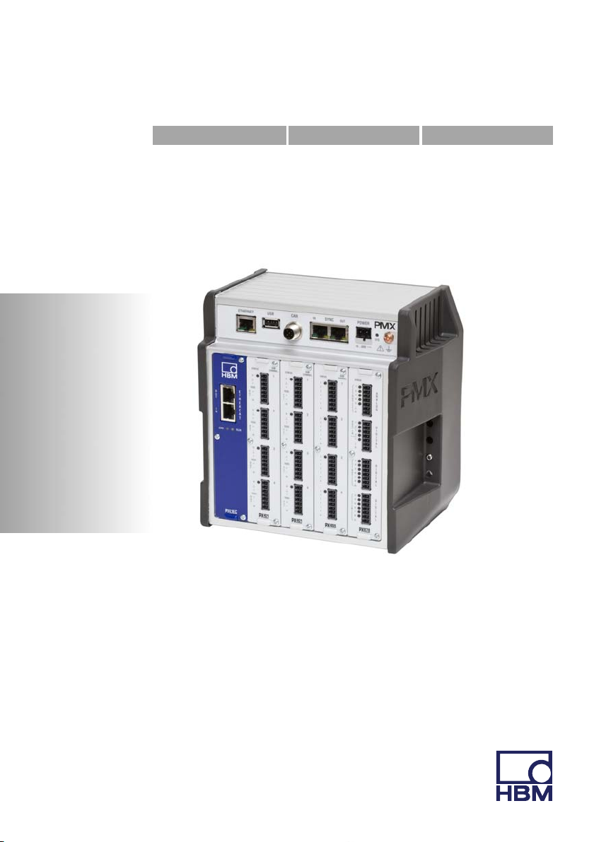
Quick Start Guide | Kurzanleitung | Guide rapide |
English Deutsch Français
PMX

Hottinger Baldwin Messtechnik GmbH
Im Tiefen See 45
D-64239 Darmstadt
Tel. +49 6151 803-0
Fax +49 6151 803-9100
info@hbm.com
www.hbm.com
Mat.: 7-2001.3259
DVS: A3259-4.0 HBM: public
03.2015
E Hottinger Baldwin Messtechnik GmbH.
Subject to modifications.
All product descriptions are for general information only.
They are not to be understood as a guarantee of quality or
durability.
Änderungen vorbehalten.
Alle Angaben beschreiben unsere Produkte in allgemeiner
Form. Sie stellen keine Beschaffenheits- oder Haltbarkeits
garantie dar.
Sous réserve de modifications.
Les caractéristiques indiquées ne décrivent nos produits
que sous une forme générale. Elles n'impliquent aucune
garantie de qualité ou de durablilité.
Quick Start Guide | Kurzanleitung | Guide rapide
English Deutsch Français
PMX

English
1 Safety instructions 3........................................
2 Purpose of the manual 3....................................
3 Symbols on the device 4....................................
4 Mounting/Dismounting/Replacing 5..........................
4.1 Mounting tools and tightening torques 5.........................
4.2 Support rail mounting 6.......................................
4.3 Wall-mounting 10.............................................
5 Quick start 13...............................................
5.1 Preparing the measurement system 13..........................
5.2 Typical operating procedure 19.................................
5.2.1 Measurement example 19.....................................
5.3 Update software (PMX web server) 24...........................
2 A3259-4.0 HBM: public PMX

1 Safety instructions
Important
Please follow the safety instructions in the PMX Ope
rating Manual, and in the separate "Safety Instruc
tions" document (enclosed with the device).
2 Purpose of the manual
This Quick Start Guide provides a quick summary of the
steps required to connect a PMX device to a PC and a
network, so that you can start to obtain measurement
results with the PMX device as quickly as possible.
An actual measurement example rounds off the Quick
Start Guide.
Safety instructions
Important
This Quick Start Guide does not replace the detailed
PMX Operating Manual.
The information provided in this Quick Start Guide is
expanded on in greater detail in:
- the Operating Manual for the PMX Measuring Am
plifier System
- the PMX web server online Help
PMX A3259-4.0 HBM: public 3
Symbols on the device
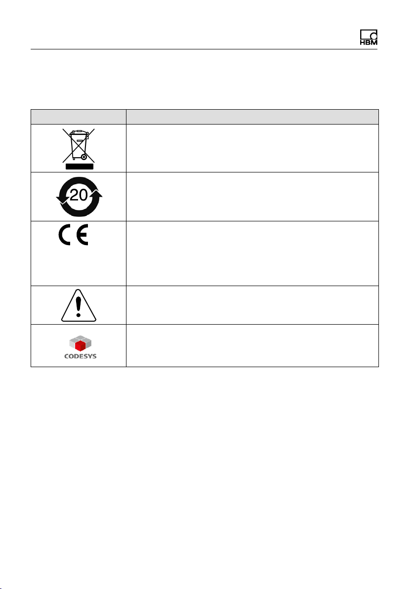
3 Symbols on the device
Symbol Meaning
Statutory waste disposal mark
Statutory mark of compliance with emission limits in electronic
equipment supplied to China
CE mark
The CE mark is used by the manufacturer to declare that the
product complies with the requirements of the relevant EC
directives (the Declaration of Conformity can be found at
www.hbm.com
Take details in the operating manual into account.
.
CODESYS is a software platform for programmable logic
controllers. The license for CODESYS is already
implemented in WG001 basic housings.
4 A3259-4.0 HBM: public PMX

Mounting/Dismounting/Replacing
4 Mounting/Dismounting/Replacing
4.1 Mounting tools and tightening torques
Mounting Required tool Tightening torque
Fasten Rail-Clip to support
rail
M 2.5 hexagon socket
screw
Mounting DIN rail on hous
ing
M5 hexagon socket
screw
Mounting front panel
M2.5 Torx screws
Mounting wall bracket
M4 hexagon socket
screw
Mounting side partes
M3 Torx screws
Grounding screw on the
PMX
M4 Torx screws
Hexagon socket screw
driver
2.5 a.f.
Hexagon socket screw
driver
3 a.f.
Torx screwdriver
TX8
Hexagon socket screw
driver
3 a.f.
Torx screwdriver
TX10
Torx screwdriver
TX20
1.0 - 1.2 Nm
3 Nm
0.5 - 0.6 Nm
1.5 … 2 Nm
0,8 … 1 Nm
1,5 … 2 Nm
PMX A3259-4.0 HBM: public 5
Mounting/Dismounting/Replacing
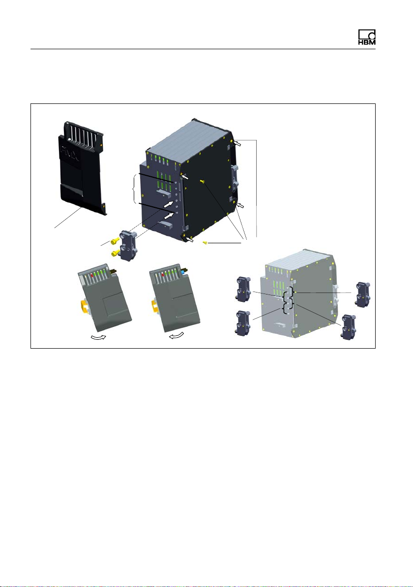
4.2 Support rail mounting
75 mm
2
Allen screw
3 mm a.f.
1
3
A
B
3
4
D
Fig. 4.1 Mounting on a support rail
► Undo the four back-panel screws (Torx T10) (1)
► Slide the side parts forward (2)
► Screw on the support rail mounting (Rail-Clip) (3) (ap
prox. 5 Nm) in a choice of four positions (A to D) (two
positions for the 7.5 mm support rail)
► Screw the side panels (2) back on
► Hook the PMX device into the support rail (4)
C
6 A3259-4.0 HBM: public PMX
Mounting/Dismounting/Replacing
Important
Device damage caused by the PMX falling due to resis
tance in hooking/unhooking the PMX.
HBM recommends using a DIN support rail (DIN EN
60715), 15 mm in height. When using a smaller support
rail (7.5 mm high), it should be shimmed to make it easy
to hook/unhook the PMX device.
The 7.5 mm support rail can only be used in the top two
positions (A and B).
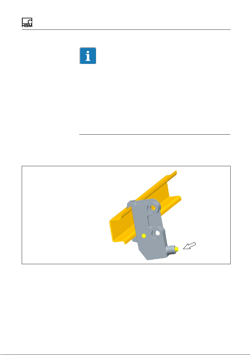
Attach the support rail mounting (Rail-Clip) to the DIN
rail
Allen screw
2.5 a.f.
At the time of delivery, the self-locking (2.5 mm a.f.) Allen
screws are unscrewed as far as the stop.
► Clip on the support rail mounting (Rail-Clip)
► Hand-tighten the self-locking Allen screw (1 - 1.2 Nm)
PMX A3259-4.0 HBM: public 7

Mounting/Dismounting/Replacing
Important
Device damage caused by electromagnetic irradiation of
external devices.
Faulty measurements due to electromagnetic irradiation
from other devices.
To ensure adequate grounding for the PMX, the support
rail must be connected to a functional earth
Both the DIN rail and the PMX must be free of paint, var
nish and dirt at the point of installation.
► Connect the PMX housing to ground via the grounding
screw.
.
8 A3259-4.0 HBM: public PMX
Mounting/Dismounting/Replacing
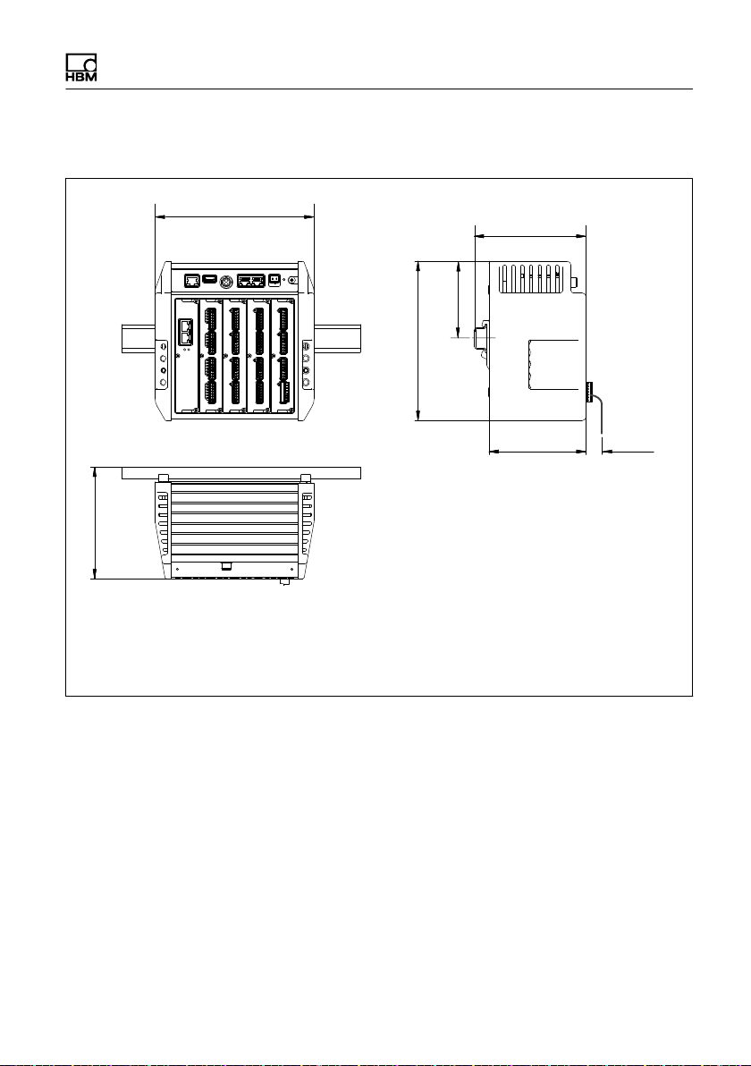
Dimensions and mounting instructions
200
200
141
*) Height of support rail 15 mm
**) Height of support rail 7.5 mm
***) Min. dimension: Plug plus sensor cable
NOTE:
To ensure sufficient ventilation/cooling, a 2 cm gap must be
maintained above and below neighboring devices.
141*)
variable
133.5**)
122
min. 25***)
PMX A3259-4.0 HBM: public 9

Mounting/Dismounting/Replacing
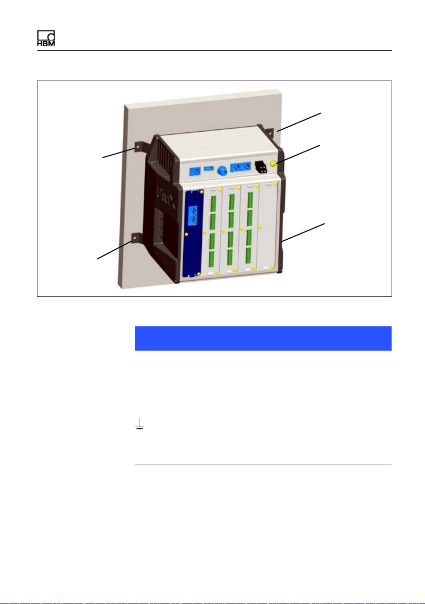
4.3 Wall-mounting
4. 3
1
225
168.5
215
Fig. 4.2 Mounting on a wall
152
► Attach the wall bracket at the back of the PMX with
the enclosed M4 screws (1) (3 Nm)
10 A3259-4.0 HBM: public PMX
Mounting/Dismounting/Replacing
Screw
M4
Screw
M4
Screw
M4
Grounding
screw
(Torx TX20)
Screw
M4
► Screw the complete unit to a wall; hole Ø 4 mm
Notice
Device damage caused by electromagnetic irradiation of
external devices.
Faulty measurements due to electromagnetic irradiation
from other devices.
The housing must also be connected to a functional earth
in a wall mounting.
► Connect the PMX housing to ground via the grounding
screw.
PMX A3259-4.0 HBM: public 11
Mounting/Dismounting/Replacing
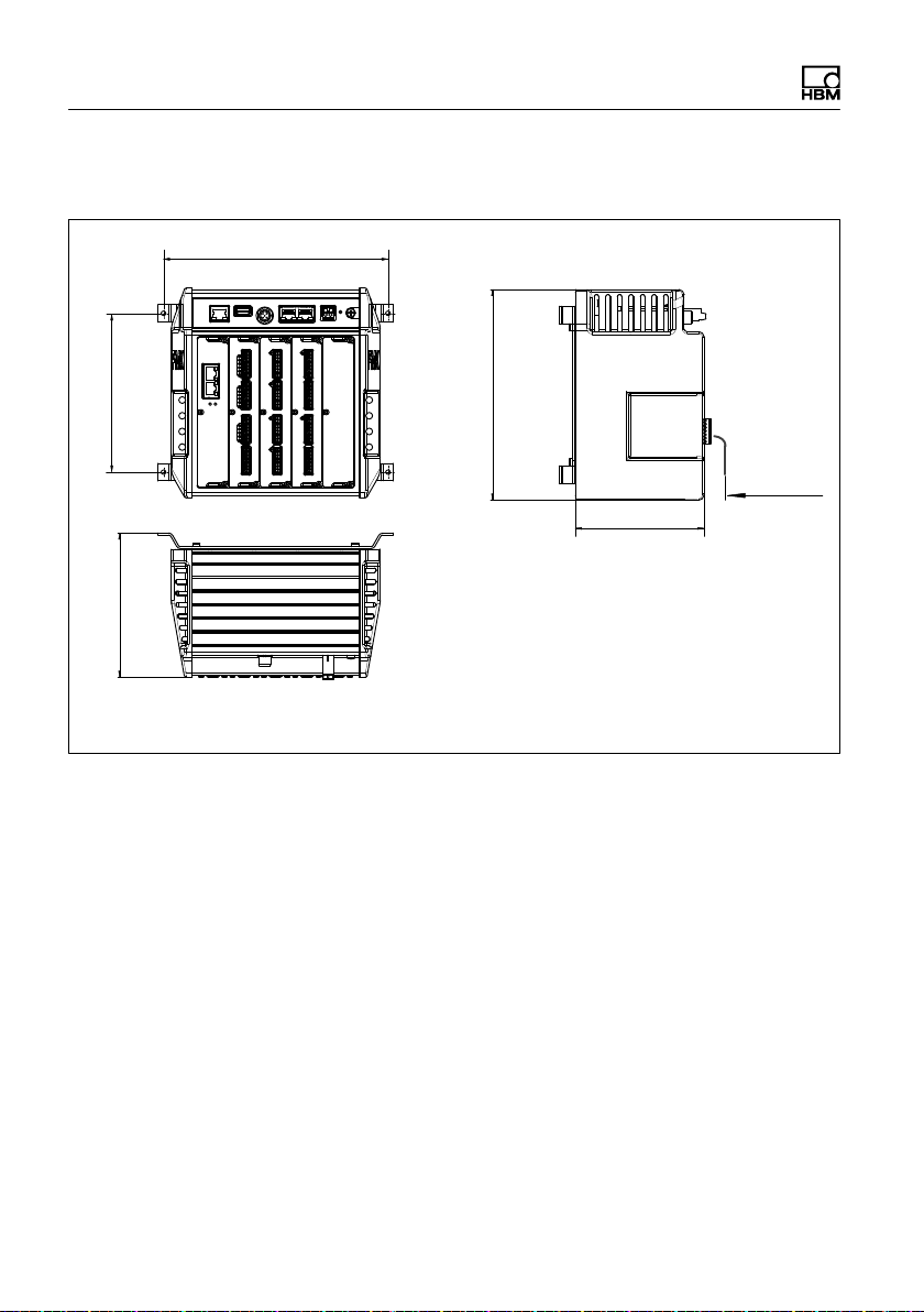
Dimensions and mounting instructions
215
152
138
200
min. 25*)
122
*) Min. dimension: Plug plus sensor cable
NOTE:
To ensure sufficient ventilation/cooling, a 2 cm
gap must be maintained above and below
neighboring devices.
12 A3259-4.0 HBM: public PMX

5 Quick start
5.1 Preparing the measurement system
1. Connect the PMX to a PC via the Ethernet socket
Cable: Standard Ethernet cable (CAT5)
2. Connect your transducers to the measurement cards
Quick start
(plug terminals)
wh
Measurement
signal (+)
bk
Bridge excitation
voltage (−)
rd
Measurement signal (−)
bu
Bridge excitation
voltage (+)
gn
Sense lead (+)
gy
Sense lead (−)
ye
Cable shield
1
2
4
3
3’
2’
Hsg.
Hsg. = Housing
Fig. 5.1 Example: Force transducer / load cell on PX455
PMX A3259-4.0 HBM: public 13
Quick start
Notice
The transducers can also be connected if you have previ
ously connected the voltage supply.
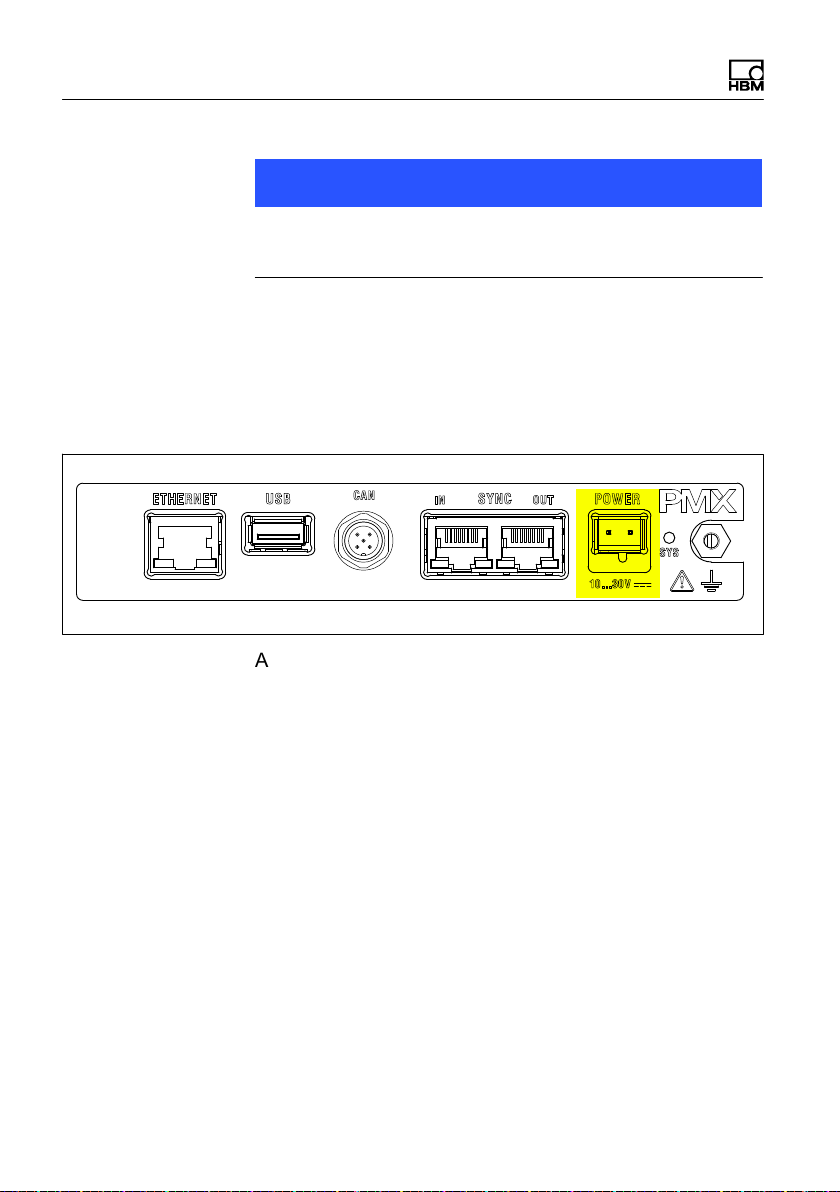
3. Connect the voltage supply (10 … 30 V DC)
The PMX boots and then displays its system status. The
system LED must light up green. This process takes a
few seconds.
At least 15 W of power must be supplied.
4. Connect the PMX to a PC (HOST)
The PMX is set to DHCP (automatic address assignment)
at the factory. Set the PC (HOST) to DHCP as well. Auto
matic adjustment and setting of the IP addresses will then
follow. This process takes a few seconds.
Call the PMX web server by entering "PMX" in the
browser bar and press RETURN.
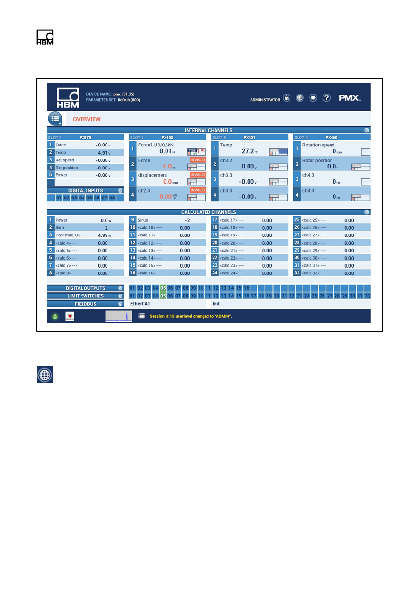
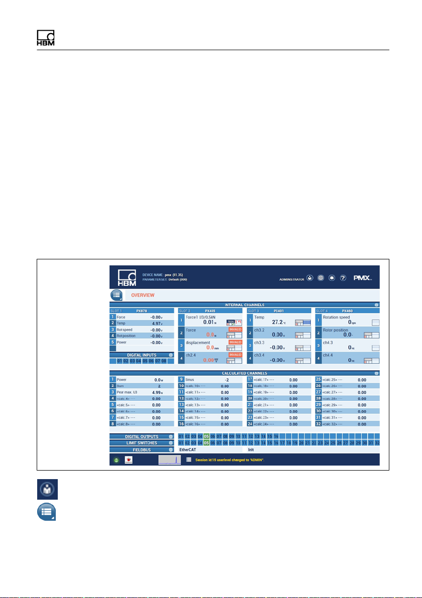
The PMX announces itself with a start screen (Overview)
14 A3259-4.0 HBM: public PMX
Quick start
The PMX system is now ready for measurement and you
can see live measured values.
► Click on the globe icon to switch to another language
of the PMX web server.
PMX A3259-4.0 HBM: public 15
Quick start
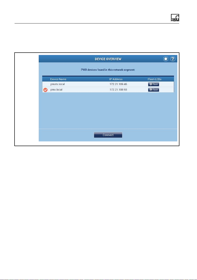
If several PMX devices are available in the network, this
selection box will also appear:
► Check the box for the required PMX
► Click Connect
The Flash function allows the device to be identified by
flashing all the device LED´s.
16 A3259-4.0 HBM: public PMX

Quick start
5. Configure the system with the web server
► Click on the user icon to go to the service or adminis
trator level. Depending on authorization, you can
make the following settings
- Assign sensors
- Assign units
- Set filter
- Monitor maximum and minimum values
- Monitor limit values
- Set up virtual (calculated) channels
- Configure digital and analog inputs / outputs
- Create and administer parameter sets
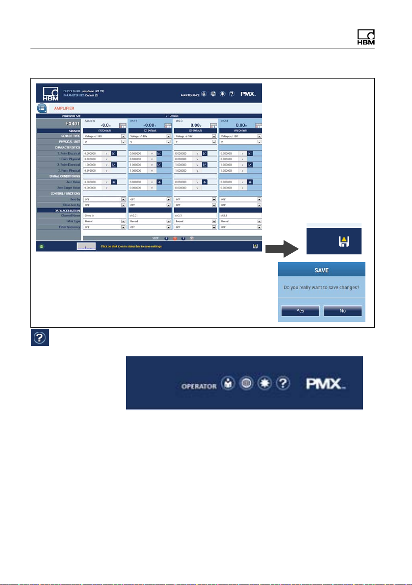
Notice
Clicking on the floppy disk symbol saves the settings/
changes power failsafe.
PMX A3259-4.0 HBM: public 17
Quick start
Security prompt
To get additional help, click the Help symbol .
This opens the web server Help.
18 A3259-4.0 HBM: public PMX
Quick start
5.2 Typical operating procedure
5.2.1 Measurement example
The easiest way to configure the PMX measuring ampli
fier and its measurement channels is via the PMX web
browser. The sensors, Ethernet cable and voltage supply
must be properly connected.
Connect the PMX to a PC (HOST) to see the device
overview.
The entire device, with all measurement cards and sig
nals, as well as all device information, is displayed here.
► Switch to the ADMINISTRATOR level (may be
password-protected), then via the menu button to
Settings/ Amplifier.
PMX A3259-4.0 HBM: public 19
Quick start
Alternatively, clicking on the required channel or function
(e.g. Limit values) directly calls up the corresponding set
tings menu. This requires authorization for the respective
user levels.
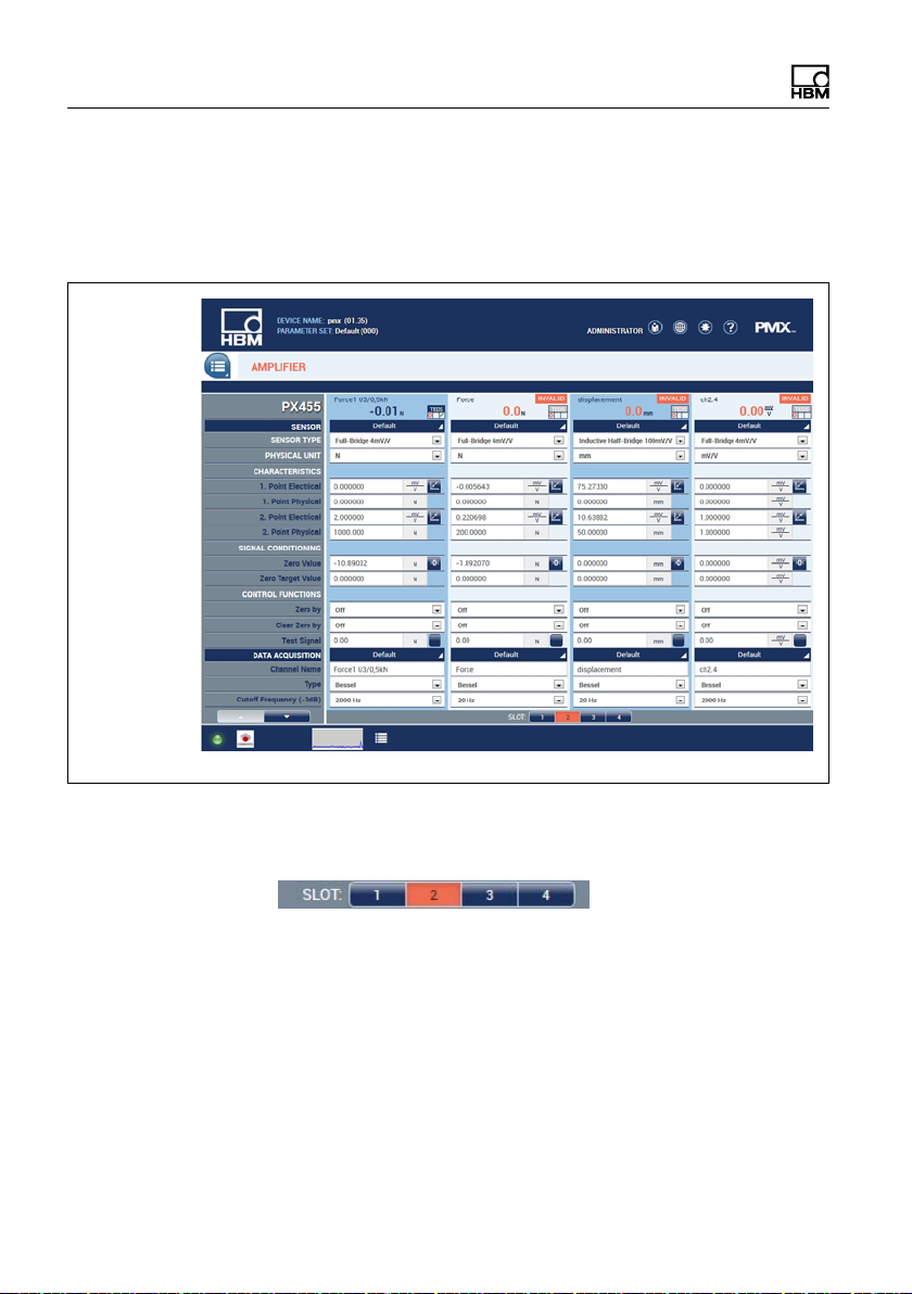
Suitable sensor and channel settings can be made here
for each module (slot) and each channel.
Click the slot numbers to select the measurement cards:
orange = selected
measurement card, blue = measurement cards present in
the PMX, gray = empty module slot (slot).
Example of force sensor at slot 3.1
In the example above, module 3 is fitted with a PX455,
and the first channel is assigned to a force sensor (SG
full bridge).
20 A3259-4.0 HBM: public PMX
Quick start
S The PMX amplifier channel is set to the full bridge
sensor type, with the measuring range of 4 mV/V.
S Amplification is set to 1,000 N, for a sensor sensitivity
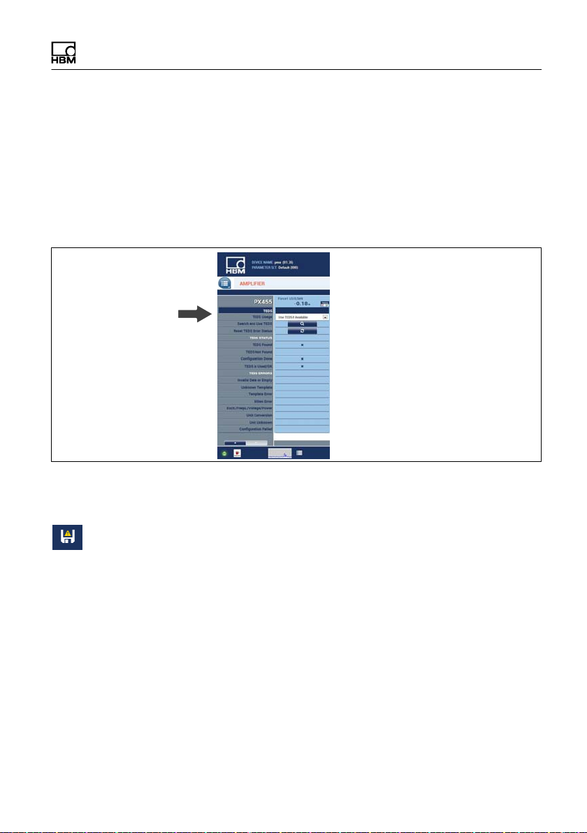
of 2 mV/V. If the sensor has TEDS sensor detection,
the amplifier channel can be parameterized automat
ically. Activation takes place on the 2nd page of the
applicable amplifier settings.
S The filter type is Bessel, the filter frequency is set to 5
Hz (average to high attenuation).
S The data are now changed in the PMX and are dis
played by a floppy disk symbol in the status line .
S Press this symbol to store the settings power failsafe
in the PMX (security prompt).
Example: Configuring the PMX with strain transducer
Example: SLB700A
Slot 2 is fitted with a PX455, its third channel is assigned
to the strain transducer.
PMX A3259-4.0 HBM: public 21
 Loading...