

HBM MX403B, MX809B Operating Manual
Operating Manual | Bedienungsanleitung |
Manuel d'emploi
English Deutsch Français
MX403B / MX809B MX403B / MX809B

Hottinger Baldwin Messtechnik GmbH
Im Tiefen See 45
D-64239 Darmstadt
Tel. +49 6151 803-0
Fax +49 6151 803-9100
info@hbm.com
www.hbm.com
Mat.: 7-2002.3757
DVS: A3757-2.2 HBM: public
05.2017
E Hottinger Baldwin Messtechnik GmbH.
Subject to modifications.
All product descriptions are for general information only.
They are not to be understood as a guarantee of quality or
durability.
Änderungen vorbehalten.
Alle Angaben beschreiben unsere Produkte in allgemeiner
Form. Sie stellen keine Beschaffenheits- oder Haltbarkeits
garantie dar.
Sous réserve de modifications.
Les caractéristiques indiquées ne décrivent nos produits
que sous une forme générale. Elles n'impliquent aucune
garantie de qualité ou de durablilité.
Operating Manual | Bedienungsanleitung |
Manuel d'emploi
English Deutsch Français
MX403B
1250 V Ut 3000 V
1000 V CAT II
600 V CAT III

English
1 Introduction 3..............................................
2 Safety instructions 6........................................
2.1 Warning signs and danger symbols 6...........................
2.1.1 Symbols on the measurement module 7........................
2.2 Proper use 7................................................
2.3 Measurement categories 9....................................
2.4 Operating conditions 11.......................................
2.5 Maintenance, repair and modification 12.........................
2.6 Cleaning 13..................................................
2.7 Transportation, storage and disposal 14.........................
2.8 Qualified Personnel 15........................................
2.9 Working safely 15.............................................
2.10 System integration 19.........................................
3 Additional markings used 20.................................
4 Scope of delivery 21.........................................
5 Accessories 22..............................................
6 MX403B operation 27........................................
6.1 Preparatory measures and starting up 27........................
6.2 Connection/measurement 28...................................
6.3 Status Display 30.............................................
7 Specifications 31............................................
2 A3757-2.2 HBM: public MX403B

1 Introduction
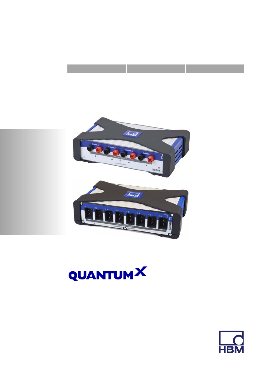
QuantumX is a modular data acquisition system from
HBM for demanding measurement and test functions.
The different inputs acquire mechanical, electrical,
hydraulic and thermal measurands, such as force, strain,
torque, pressure, displacement, temperature, rotational
speed, acceleration, position, flow rate, voltage, etc.
The MX403B voltage measurement module can measure
voltages as high as 1000 V, as well as small differential
voltages at high electric potential.
The QuantumX family documentation basically com
prises:
S The current operating manual for the voltage mea
S A quick start guide for initial start-up (available in
S Data sheets for the individual modules and acces
S The QuantumX operating manual with connection
S The operating manual for the EtherCAT
surement module (available in printed form)
printed form)
sories
descriptions and possible system topologies and
states
1)
/ Ethernet
Gateway CX27
S The operating manual for data recorder CX22-W /
CX22
S A comprehensive online help with index and easy
search options which is available after the installation
1)
EtherCAT® is a registered brand and patented technology, licensed by Beckhoff Automation
GmbH, Germany
MX403B A3757-2.2 HBM: public 3

of a software package (e.g. QuantumX Assistant, cat
man
EASY)
These documents can be found:
S On the QuantumX system CD supplied with the device
S After installing the QuantumX Assistant on the hard
drive of your PC
S Up-to-date versions are always available from our
Internet site at http://www.hbm.com/hbmdoc
Notice
When working with the MX403B, always take note of the
standard operating manual (I2322) as well.
The high level of protection of the MX403B is guaranteed
by consistent development in accordance with the latest
conditions specified in the measuring equipment stan
dards IEC 61010-1:2010+Cor.:2011 and
IEC 61010-2-030:2010+Cor.:2011, as well as by VDE
certification and production monitoring.
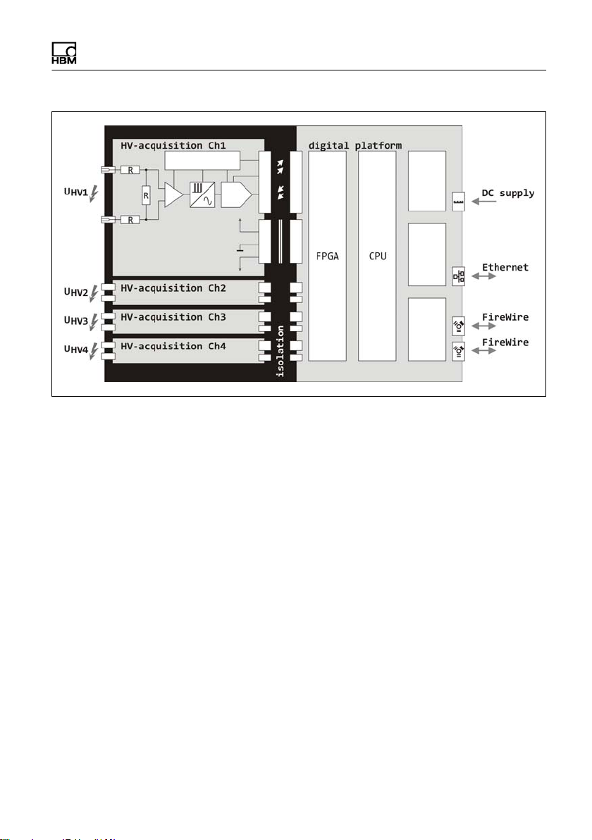
The MX403B has four insulated differential measurement
channels for directly measuring voltages up to 1000 V DC
or 1000 V rms AC.
The different measuring ranges allow the acquisition of
high voltages to remote ground, as well as the measure
ment of small differential voltages at high potential to
remote ground.
The connection is made with 4 mm safety lab jacks,
19 mm pitch, suitable for standardized BNC adapters.
Each channel is equipped with a programmable amplifier,
analog reconstruction and antialiasing filters, a 24bit
ADC and digital filters.
4 A3757-2.2 HBM: public MX403B
MX403B A3757-2.2 HBM: public 5
2 Safety instructions
This measurement module is built and tested in accor
dance with EN 61010, Safety Requirements for Electrical
Equipment for Measurement, Control and Laboratory
Use, and was in perfect condition when it left production.
To maintain this condition and ensure risk-free operation
(reducing residual risks, EN 610101:2010 17 c), the user
must comply with the instructions and warning notices
contained in this operating manual.
2.1 Warning signs and danger symbols
Important instructions for your safety are specifically iden
tified. It is essential to follow these instructions in order to
prevent accidents and damage to property.
DANGER
This marking warns of an imminently threatening danger
ous situation which - if safety requirements are disregarded
- will result in death or serious physical injury.
Notice
This marking draws attention to a situation which - if dis
regarded - can result in damage to property.
6 A3757-2.2 HBM: public MX403B
2.1.1 Symbols on the measurement module
Take details in the operating manual into account
Read and comply with the operating manual.
2.2 Proper use
The MX403B voltage measurement module fits perfectly
into the modular QuantumX series and is solely used to
measure high differential voltages or differential voltages
at high potential to remote ground, within the ratings
stated in the specifications.
The device is not intended for use as a safety compo
nent. Please also refer to the section: "Additional safety
precautions".
Proper and safe operation requires proper transportation,
correct storage, siting and mounting, and careful opera
tion.
Everyone involved with siting, starting up, or operating
the measurement module must have read and under
stood the operating manual and in particular the technical
safety instructions.
In the interests of safety, the measurement module
should only be operated by qualified personnel (see
below) and as described in the operating manual. It is
also essential to comply with the legal and safety require
ments for the application concerned during use. The
same applies to the use of accessories.
MX403B A3757-2.2 HBM: public 7
DANGER
If the measurement module is not used as intended, the
protection provided by the measurement module may be
impaired.
DANGER
If the measurement module is used outside the ratings,
the protection provided by the measurement module may
be impaired.
8 A3757-2.2 HBM: public MX403B
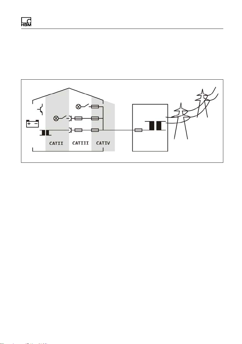
2.3 Measurement categories
The MX403B is designed for applications in measure
ment categories CAT II and CAT III:
CAT II
Measurement category II is applicable to test and mea
suring circuits that are directly connected to the user con
nections (sockets) of the low-voltage grid installation. It is
expected that this part of the installation will have at least
three levels with overload protection elements between
the transformer and the measuring circuit connection
point.
CAT III
Measurement category CAT III is applicable to test and
measuring circuits that are connected to the distribution
circuit of the building low-voltage grid installation. It is
expected that this part of the installation will have at least
two levels with overload protection elements between the
transformer and the measuring circuit connection point.
MX403B A3757-2.2 HBM: public 9
DANGER
For all other applications at the low-voltage installation
there is a risk related to:
S Electric shock
S Arc flash burns
S Arc blast explosion and
S Other phenomena
The MX403B is only suitable for rated voltages within the
measurement categories described - the MX403B is not
suitable for any other applications at the low-voltage
installation and its use here is not permitted.
Outside the measurement categories
The following applies to test and measuring circuits with
out a rated measurement category (formerly CAT I):
Whether the MX403B is suitable for test or measuring
circuit applications not intended for direct connection to
the supply network can only be determined by an accu
rate analysis of the operating voltage, peak voltage, loop
impedance, occasional overvoltage and transient over
voltage of these circuits. The following characteristics
apply to the MX403B in this respect:
S Peak voltage: max. 1250 V
S Loop impedance: min. 100 m
(see EN 61010-2-030:2011 Table AA.1)
S Occasional overvoltage: none
S Transient overvoltage: "3000 V
10 A3757-2.2 HBM: public MX403B

2.4 Operating conditions
S See the specifications for the permissible operating
temperature, as well as the permissible storage and
transportation temperatures. If the MX403B has been
stored or transported in extreme temperatures, you
must wait for at least 2 hours before switching it on.
S Do not expose the measurement module to direct
sunlight. The protection provided by the MX403B may
be impaired if the device is exposed to intense sun
light for too long, including behind car windows, for
example.
S The operating position is optional.
S Protect the measurement module against direct con
tact with water and moisture, as well as weather con
ditions such as rain or snow. Should condensation
have formed during transportation or storage, the
MX403B must be acclimatized for at least 2 hours
before being put into operation.
S Do not operate the measurement module above the
maximum operational height of 2000 m.
S The MX403B is designed for use in clean and dry
rooms with degree of pollution 2; cables must not be
routed through outdoor areas. It must not be operated
where the air has a particularly high dust content,
where there is a risk of explosion or in an aggressive
chemical environment.
DANGER
If the measurement module is used outside the rated
operating conditions, the protection provided by the mea
surement module may be impaired.
MX403B A3757-2.2 HBM: public 11
2.5 Maintenance, repair and modification
S The measurement module is maintenance-free.
S The measurement module, including the measure
ment cable and the safety connector, must not be
changed or modified in any way.
S Only trained and qualified personnel who are autho
rized to do so by HBM are allowed to open the
MX403B. Before opening the measurement module,
the feeding QuantumX module must be switched off
and the MX403B disconnected from all circuits. Oper
ation when open is not allowed. Once the device has
been opened, it must be professionally inspected in
accordance with EN 61010-1 Annex F, before starting
it up again.
S The measurement module is delivered from the fac
tory with a fixed hardware and software configuration.
Changes can only be made within the possibilities
documented in the manuals.
S The measurement module must not be modified from
the design or safety engineering point of view except
with our express agreement. In particular, any repair
or soldering work on motherboards (exchanging com
ponents) is prohibited. When exchanging complete
modules, use only original parts from HBM.
DANGER
If the measurement module is opened, modified or inex
pertly repaired, the protection provided by the measure
ment module may be impaired.
12 A3757-2.2 HBM: public MX403B
2.6 Cleaning
Please note the following points when cleaning the hous
ing:
S Disconnect the measurement module from all current
and voltage supplies.
S Also switch off the feeding QuantumX module.
S Clean the housing with a soft, slightly damp (not wet!)
cloth. Never use solvent as this could damage the
labeling or the housing.
S When cleaning, ensure that no liquid gets into the
measurement module or connections.
S Give the MX403B sufficient time to dry before starting
it up again.
DANGER
If the measurement module is not properly cleaned, the
protection provided by the measurement module may be
impaired.
MX403B A3757-2.2 HBM: public 13
2.7 Transportation, storage and disposal
S When unpacking the contents of the package, check
that everything is present. When it is unpacked, the
MX403B should be inspected for mechanical damage.
If damage has occurred during transit, the measure
ment module must not be operated. Keep the original
packaging in case subsequent transportation is nec
essary. Any shipping damage caused by inadequate
packaging is excluded from the warranty.
S Store the MX403B somewhere dry and enclosed. If
the MX403B has been transported at extreme temper
atures, you should wait for at least 2 hours to allow
the device to acclimatize, before switching it on.
S In accordance with national and local environmental
protection, material recovery and recycling regula
tions, old measurement modules that can no longer
be used must be disposed of separately and not with
normal household waste.
DANGER
If the measurement module is damaged, operated with
out being acclimatized, or incorrectly stored or trans
ported, the protection provided by the measurement mod
ule may be impaired.
14 A3757-2.2 HBM: public MX403B
2.8 Qualified Personnel
Qualified persons means persons entrusted with the
installation, fitting, commissioning and operation of the
product who possess the appropriate qualifications for
their function.
S For measurements covered by the low voltage direc
tive, the measurement module must only be con
nected by a qualified electrician, or by someone with
electrical training under the supervision of a qualified
electrician. (A qualified electrician is someone whose
technical training, know-how and experience, as well
as knowledge of the relevant requirements, allows
them to assess the work assigned to them and to rec
ognize potential risks, and who has been designated a
qualified electrician by the contractor).
DANGER
Personnel who are not sufficiently qualified are particu
larly exposed to the risk related to electric shock, arc
flash burn, arc blast explosion and other phenomena.
2.9 Working safely
S When it is unpacked, check the measurement module
for visible signs of damage. If damage has occurred,
the MX403B must not be operated.
S Error messages should only be acknowledged once
the cause of the error is removed and no further dan
ger exists.
MX403B A3757-2.2 HBM: public 15
S The measurement module and devices used in auto
mation must be covered over in such a way that ade
quate protection or locking against unintentional actu
ation is provided (e.g. access checks, password
protection, etc.).
S For those measurement modules operating in net
works, safety precautions must be taken in terms of
both hardware and software, so that a line break or
other interruptions to signal transmission do not cause
undefined states or loss of data in the automation
device.
S After making settings and carrying out activities that
are password-protected, ensure that any controls that
may be connected remain in a safe condition until the
switching performance of the measurement module
has been tested.
S The maximum cable length must not exceed 30 m.
It is not acceptable to run cables through outdoor
areas.
S Measurement signals can only be applied to the
MX403B once it has been connected to a QuantumX
application (such as the QuantumX Assistant).
DANGER
Voltages with no energy limit that exceed one of the fol
lowing values are rated as dangerous according to EN
61010:
1. AC voltage, 33 V rms value
2. AC voltage, 46 V peak value
3. DC voltage, 70 V
16 A3757-2.2 HBM: public MX403B

Higher voltages must only be applied by qualified person
nel who are familiar with the dangers involved! It is
essential to comply with the related safety regulations!
DANGER
When applying dangerous contact voltages to the mea
suring connections, you must comply with all the related
safety requirements!
DANGER
Risk related to unsuitable accessories. The measurement
module is specified according to EN 61010 for 600 V
CAT III or 1000 V CAT II. Only accessories approved for
at least this category can be used or connected to the
measuring connections.
DANGER
Risk due to poor insulation of external circuits: Only
devices that comply with the requirements of IEC
610101, 610102030 and IEC 60950 may be connected
MX403B A3757-2.2 HBM: public 17
DANGER
To avoid injury from coming into contact with dangerously
active potential: do not wear jewelry (rings, watches, etc.)
and do not touch any live parts. Comply with safety rules:
isolate, secure, check, ground and short-circuit, cover
and safeguard.
DANGER
In the following situations, the measurement module must
be shut down and secured to prevent inadvertent opera
tion:
S Visible signs of damage to the measurement module
S The MX403B cannot be connected to a QuantumX
application
S (Audibly) loose parts in the measurement module
S The measurement module no longer works
18 A3757-2.2 HBM: public MX403B
2.10 System integration
S If the MX403B is integrated into a system, it is the
responsibility of the system installer to keep the sys
tem safe.
S Additional safety precautions to meet the require
ments of the relevant national and local accident pre
vention regulations must be taken in plants where
malfunctions could cause major damage, loss of data
or even personal injury.
The scope of supply and performance of the measure
ment module covers only a small area of measurement
technology. Before starting up the measurement module
in a system, a project planning and risk analysis must first
be implemented, taking into account all the safety
aspects of measurement and automation technology so
that residual dangers are minimized. This particularly
concerns personal and machine protection. In the event
of a fault, the relevant precautions must establish safe
operating conditions.
DANGER
Additional risks may occur when the measurement mod
ule is integrated into plants or systems, and the protec
tion provided by the measurement module may be
impaired.
MX403B A3757-2.2 HBM: public 19

3 Additional markings used
CE certification
The CE mark enables the manufacturer to guarantee that
the product complies with the requirements of the rele
vant EC directives (the Declaration of Conformity can be
found at www.hbm.com).
Statutory waste disposal mark
In accordance with national and local environmental pro
tection, material recovery and recycling regulations, old
measurement modules that can no longer be used must
be disposed of separately and not with normal household
waste.
If you need more information about disposal, please con
tact your local authorities or the dealer from whom you
purchased the product.
20 A3757-2.2 HBM: public MX403B

4 Scope of delivery
S MX403B QuantumX voltage measurement module
S Operating manual
MX403B A3757-2.2 HBM: public 21
5 Accessories
The MX403B voltage measurement module is specified
according to EN 61010 for 600 V CAT III or 1000 V
CAT II. Only accessories approved for at least this cate
gory can be used and connected to the measuring con
nections.
ments of IEC 610101, 610102030 and IEC 60950 may
be connected.
The recommended HBM 1NTX001 accessory meets the
requirements of IEC / EN / DIN EN 609501 regarding a
SELV power supply. The direct current supply of the
MX403B must be a SELV voltage supply that meets the
requirements of IEC / EN / DIN EN 609501. The supply
voltage must be protected where applicable by a suitable
DC fuse (e.g. LITTELFUSE KLKD 6, LFPHV001).
General accessories
Article Description Order No.
AC/DC power supply /
24 V
Cable - QuantumX
supply
Ethernet crossover
cable
Input: 100 - 240 V AC ("10%),
1.5 m cable
Output: 24 V DC, max. 1.25 A,
2 m cable with ODU plug
3 m cable for voltage supply of QuantumX
modules; suitable plug (ODU Medi-Snap
S11M08-P04MJGO-5280) at one end and
exposed wires at the other
Ethernet crossover cable for direct opera
tion of devices on a PC or notebook, length
Only devices that comply with the require
1-NTX001
1-KAB271-3
1-KAB239-2
2 m, type CAT5+
22 A3757-2.2 HBM: public MX403B
IEEE1394b FireWire
cable
(module-to-module)
IEEE1394b IEEE1394b
FireWire IEEE Ex
pressCard
IEEE1394b FireWire
cable, PC to module
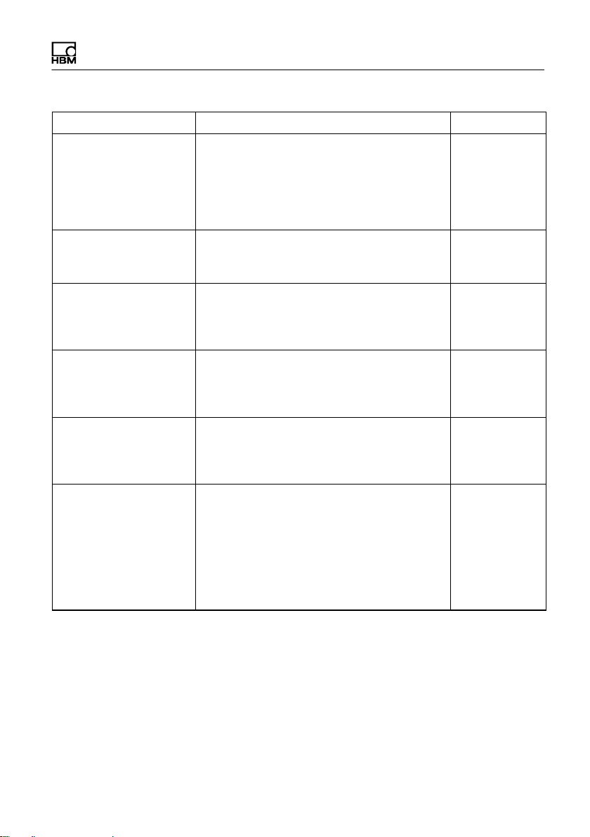
Connecting elements
for QuantumX modules
Connecting elements
for QuantumX modules
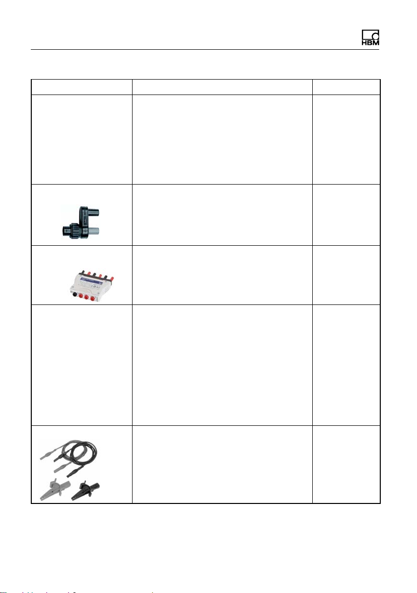
QuantumX Backplane
(Standard)
FireWire connection cable between Quan
tumX modules, fitted with suitable plugs on
both ends; lengths 0.2 m/2 m/5 m. Note:
voltage can also be supplied to the Quan
tumX modules via the cable (max. 1.5 A,
from source to last acceptor)
FireWire IEEE 1394b ExpressCard (Ex
pressCard/34) to connect QuantumX mod
ules to a notebook or PC
FireWire connection cable from PC to the
first module. For data transmission from
QuantumX modules to the PC. Fitted with
suitable plugs at both ends. Length: 5 m
Connecting elements (clips) for QuantumX
modules; set comprising 2 case clips and
including assembly material for fast con
nection of 2 modules
Fitting panel for mounting QuantumX mod
ules using case clips (1-CASECLIP), lash
ing strap or cable ties. Basic fastening by
4 screws
QuantumX Backplane – Standard for a
maximum of 9 modules;
General:
- Mounting on wall or control cabinet (19”)
Connection of external modules by
FireWire possible;
Power supply: 24 V DC / max. 5 A (150
W);
Order No.DescriptionArticle
1-KAB272-0.2
1-KAB272-2
1-KAB272-5
1-IF002
1-KAB293-5
1-CASECLIP
1-CASEFIT
1-BPX001
MX403B A3757-2.2 HBM: public 23
QuantumX Backplane
(Rack)
BNC-banana adapter BNC socket safety adapter to 2 x 4 mm
QuantumX Backplane – Rack
for maximum 9 modules;
19'' rack mounting with handles left and
right;
Connection of external modules via
FireWire possible;
Power supply: 24 V DC / max. 5 A (150
W).
bananas, 4 per set. 1000 V CAT II, 600 V
CAT III and 1 A nominal (rated) current
Order No.DescriptionArticle
1-BPX002
HBM
1-G067-2
„Artificial star“ to banana
plug adapter
Isolated shielded test
leads
Test leads and clips Black/red lead set 600 V RMS CAT II, 1.5
Pluggable artificial star for attaching to the
MX403B
Black/red lead set combined within
shielded housing (Yellow). 600 V RMS
CAT II, safety-shrouded stackable banana
plugs. Significantly reduces signal distur
bance pickup on GN610/
GN611/GN610B/GN611B cards by using
two identical signal wires with earthed
shield.
Do not use for 3 wire connections!
Available lengths: 1.5 m (4.92 ft), 3.0 m
(9.84 ft) and 6.0 m(19.69 ft)
meter (4.9 ft) with safety-shrouded banana
plugs and alligator clips.
For better noise immunity, HBM recom
mends to use KAB290 in stead of this
cables set.
1-G068-2
1-KAB290-1.5
1-KAB290-3
1-KAB290-6
1-KAB282-1.5
24 A3757-2.2 HBM: public MX403B
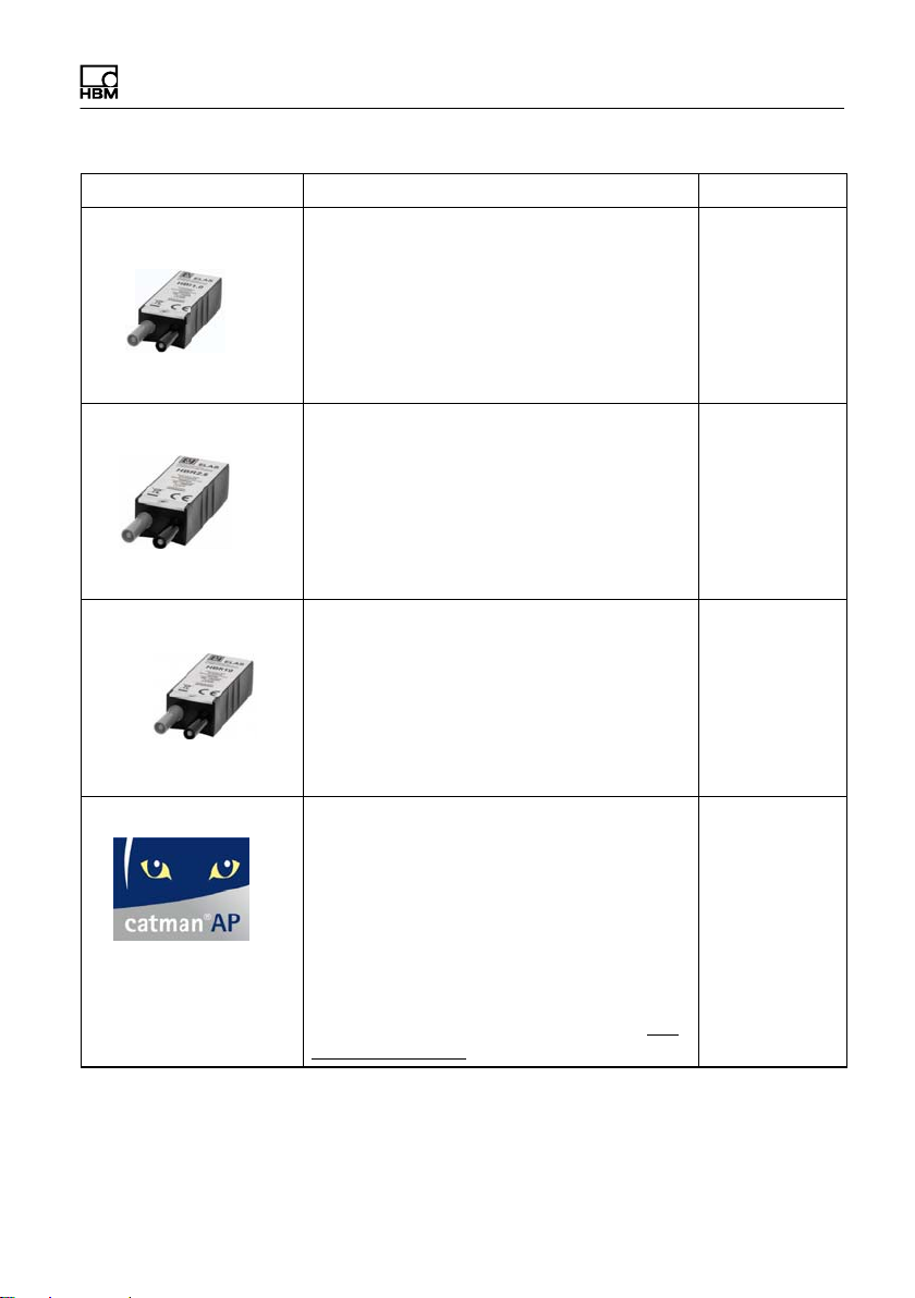
HBR 1 W, 1 W
precision burden resis
tor
1 W, 1 W, 0.02% high precision, low thermal
drift burden resistor. Internally uses 4 wire
connection to reduce inaccuracy caused by
the currents running to the burden resistor.
Using banana input connectors and
banana output pins. Directly compatible
with GN610, GN611, GN610B and GN611B
acquisition cards.
HBR 2.5 W, 1 W
precision burden resis
tor
resistor
2.5 W, 1 W, 0.02% high precision, low ther
mal drift burden resistor. Internally uses 4
wire connection to reduce inaccuracy
caused by the currents running to the bur
den resistor. Using banana input connec
tors and banana output pins. Directly com
patible with GN610, GN611, GN610B and
GN611B acquisition cards.
HBR 10 W, 1 W
precision burden
resistor
resistor
10 W, 1 W, 0.02% high precision, low ther
mal drift burden resistor. Internally uses 4
wire connection to reduce inaccuracy
caused by the currents running to the bur
den resistor. Using banana input connec
tors and banana output pins. Directly com
patible with GN610, GN611, GN610B and
GN611B acquisition cards.
catmanAP Complete package including catmanEasy
functionality plus additional modules such
as integration of video cameras
(EasyVideoCam), complete postprocess
analysis (EasyMath), automation of recur
ring processes (EasyScript), offline prepar
ation of measurement projects (EasyPlan)
as well as additional functions such as cal
culating electrical power, special filters, fre
quency spectrum, etc. More details at
w.hbm.com\catman\
ww
Order No.DescriptionArticle
1-HBR/1 Ohm
1-HBR/
1.5 Ohm
1-HBR/
10 Ohm
1-CATMANAP
MX403B A3757-2.2 HBM: public 25
catmanEASY
The basic software package for measure
ment data acquisition comprises conveni
ent channel parameterization using TEDS
or the sensor database, measurement job
parameterization, individual visualization,
data storage and reporting.
Order No.DescriptionArticle
1-CATMANEASY
catmanPostProcess
LabVIEWTM‐driver
1)
CANape driver
Post Process edition for visualization, pre
paration and analysis of measurement
1-CATEASY-
PROCESS
data, including many
mathematical functions, data export and
reporting.
Universal driver from HBM for LabVIEWTM. 1-LabVIEW-
DRIVER
QuantumX driver for the software
CANape
from Vector Informatik. CANape
1-CANAPE-
DRIVER
versions from 10.0 are supported.
26 A3757-2.2 HBM: public MX403B
6 MX403B operation
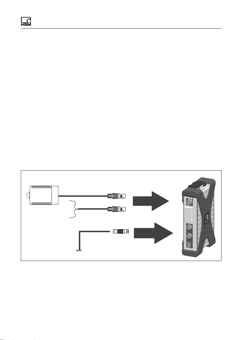
6.1 Preparatory measures and starting up
► Install a QuantumX application (such as the
QuantumX Assistant) on a PC.
► Use FireWire or Ethernet to establish a physical data
link between the MX403B and the PC.
► Supply the MX403B with a DC voltage of 10 V - 30 V
(24 V recommended).
The direct current supply must be a SELV voltage
supply that meets the requirements of IEC / EN / DIN
EN 609501. The supply voltage must be protected
where applicable by a suitable DC fuse (e.g. LITTEL
FUSE KLKD 6, LFPHV001).
NTX001
Or
1-Kab271-3
1-Kab272
FireWire
► Make sure that all the disconnecting devices and the
emergency stop and emergency OFF devices are
easily accessible and can be reached by third parties
EN 610101:2010 5.4.4 b
MX403B A3757-2.2 HBM: public 27

6.2 Connection/measurement
► Before connecting the voltage source to be measured,
check that the MX403B is working. This is done with a
calibrated reference source or by measuring the refer
ence voltage in advance with a calibrated voltmeter.
► Connect the MX403B to the voltage source to be
measured.
- Only extend the measuring lead with measuring
leads approved for CAT II 1000 V or CAT III 600 V,
or better.
- The maximum permissible length of the measuring
lead is 30 m.
- The measuring lead must not run through outdoor
areas, either in full or in part.
► To reduce interference signals:
- Keep the measuring leads as short as possible.
- Connect the MX403B housing to ground potential.
- Use pairs of shielded cables (ensure approval),
connect the shield to ground potential.
- Route unshielded measuring leads close together,
channel by channel; avoid large loop areas.
- Twist the unshielded measuring leads together.
- Physically separate leads for measuring sensitive,
small signals from measuring leads connected to
sources that are subject to interference or highly
dynamic.
- Do not route measuring leads next to potentially
interfering devices such as motors, inverters, etc.
28 A3757-2.2 HBM: public MX403B
 Loading...