

Page 1

Operating Manual
English
Quantum
X
Page 2

Hottinger Baldwin Messtechnik GmbH
Im Tiefen See 45
D-64239 Darmstadt
Tel. +49 6151 803-0
Fax +49 6151 803-9100
info@hbm.com
www.hbm.com
Mat.: 7-2002.3031
DVS: I3031-14.0 HBM: public
09.2016
E Hottinger Baldwin Messtechnik GmbH.
Subject to modifications.
All product descriptions are for general information only.
They are not to be understood as a guarantee of quality or
durability.
Page 3

English
1 Safety instructions 8........................................
2 Electro magnetic conformity 15...............................
3 Markings used 17............................................
3.1 The markings used in this document 17..........................
3.2 Symbols on the device 18......................................
4 Introduction 19..............................................
4.1 About the QuantumX documentation 19.........................
4.2 The QuantumX family 20......................................
4.3 Module overview/transducer technologies 24.....................
4.4 Digitalization and signal path 25................................
4.5 Synchronization 26............................................
5 Software 35.................................................
5.1 MX Assistant 35..............................................
5.2 catman®AP 37...............................................
5.3 LabVIEW® driver / library 38...................................
5.4 Driver for Microsoft® Visual Studio .NET 39......................
5.5 Other drivers 39..............................................
5.6 Firmware update via Ethernet 40................................
6 Mechanical 41...............................................
6.1 Mounting case clips on modules 42.............................
6.2 Connecting housings 45.......................................
6.3 Mounting the housing with CASEFIT 47..........................
6.4 BPX001/BPX002 backplane 47.................................
6.4.1 Connection 49................................................
6.4.2 Backplane BPX001 50.........................................
6.4.3 Backplane BPX002 52.........................................
6.4.4 Mounting the modules 52......................................
6.4.5 Backplane with Ethernet connection 56..........................
Quantum
X
I3031-14.0 HBM: public 3
Page 4

6.4.6 Backplane with IEEE1394b FireWire connection 57...............
6.4.7 System layout with several backplanes 58........................
7 Connecting individual QuantumX modules 59.................
7.1 Connecting the supply voltage 59...............................
7.2 Connection to host PC or data recorder 62.......................
7.2.1 Single Ethernet connection 62..................................
7.2.2 Multiple Ethernet connection with PTP synchronization 63..........
7.2.3 Multiple Ethernet connection and FireWire synchronization 64......
7.2.4 Connecting one or more QuantumX modules to the PC 65.........
7.2.5 Firmware update via Ethernet 73................................
7.2.6 Connection via FireWire (IEEE 1394b) 74........................
7.2.7 Setting up FireWire 1394b on the PC 75.........................
7.2.8 Multiple FireWire connection 77.................................
7.2.9 Layout with data recorder CX22B‐W 78..........................
7.2.10 Output measurement signals to CAN bus (MX840B) 79............
7.2.11 Output measurement signals to CAN bus (MX471B) 79............
7.2.12 Output of signals with standardized voltage in real time (MX878B
or MX879B) 80...............................................
7.2.13 Output signals in real time via EtherCAT® and in parallel
via Ethernet 81...............................................
7.2.14 QuantumX in the FireWire group 82.............................
7.2.15 Optical FireWire connection 85.................................
8 Modules and transducers 87.................................
8.1 General information 87........................................
8.1.1 Shielding design 87...........................................
8.1.2 Active transducer connection 89................................
8.1.3 TEDS 91....................................................
8.1.4 Background calibration / autoadjustment 94......................
8.2 MX840/A/B universal amplifier 96...............................
8.2.1 MX840B pin assignment 98....................................
4 I3031-14.0 HBM: public Quantum
X
Page 5

8.2.2 MX840B status display 100.....................................
8.3 MX440B universal amplifier 101..................................
8.4 MX410B highly dynamic universal amplifier 103....................
8.4.1 MX410B pin assignment 104....................................
8.4.2 MX410B status display 106.....................................
8.5.1 MX430B pin assignment 108....................................
8.5.2 MX430B status display 109.....................................
8.6.1 MX238B pin assignment 111....................................
8.6.2 MX238B status display 112.....................................
8.7 MX460B frequency amplifier 113.................................
8.7.1 MX460B pin assignment 114....................................
8.7.2 MX460B status display 116.....................................
8.8 MX1609KB and MX1609TB thermocouple amplifier 117............
8.8.1 Thermocouple with TEDS functionality (RFID) 119.................
8.8.2 MX1609 status display 121......................................
8.9 MX471B CAN module 122......................................
8.9.1 General information 122........................................
8.9.2 MX471B pin assignment 124....................................
8.9.3 LEDs status display 125........................................
8.9.4 Receiving CAN messages 126...................................
8.10 MX1601B amplifier 127.........................................
8.10.1 MX1601B pin assignment 128...................................
8.10.2 MX1601B status display 130....................................
8.11 MX1615B amplifier 132.........................................
8.11.1 MX1615B pin assignment 134...................................
8.11.2 MX1615B status display 136....................................
9 Transducer connection 138....................................
9.1 Full bridge, SG 138............................................
9.2 Full bridge, inductive 139.......................................
9.3 Full bridge, piezoresistive 140...................................
9.4 Half bridge, SG 141............................................
Quantum
X
I3031-14.0 HBM: public 5
Page 6

9.5 Half bridge, inductive 142.......................................
9.6 Quarter bridge, SG 143.........................................
9.7 Adapter quarter bridge, SG 144..................................
9.8 Connecting transducers with double shield technique 145...........
9.9 Potentiometric transducers 146..................................
9.10 LVDT transducers 147..........................................
9.11 Current-fed piezoelectric transducer (ICP/IEPE) 148...............
9.12 Electrical voltage 100 mV 150...................................
9.13 DC voltage sources 10 V 151....................................
9.14 DC voltage sources 60 V 152....................................
9.15 Voltage sources up to 300 V (CAT II) 153.........................
9.16 DC current sources 20 mA 154..................................
9.17 DC current sources 20 mA - voltage-fed 155.......................
9.18 Ohmic resistance (e.g. PTC, NTC, KTY, …) 156...................
9.19 Resistance thermometer PT100, PT1000 157......................
9.20 Thermocouples 158............................................
9.21 Frequency, differential, without directional signal 161...............
9.22 Frequency, differential, with directional signal 162..................
9.23 Frequency, single-pole, with directional signal 163..................
9.24 Encoder and pulse encoder, differential 164.......................
9.25 Encoder and pulse encoder, single-pole 165.......................
9.26 Rotary encoder and pulse generator, single pole with static
directional signal 166...........................................
9.27 Absolute value encoder with SSI protocol 167.....................
9.28 Passive inductive encoder (Pickups, Crankshaft sensor) 169........
9.29 Measurement of rotational speed, Crankshaft sensor (digital, TTL) 170
9.30 PWM - Pulse width, pulse duration, period duration 171.............
9.31 PWM - Pulse width, pulse duration, period duration, single-pole 172..
9.32 CAN bus 173..................................................
10 Functions and outputs 175....................................
10.1 MX410B and MX430B 176......................................
6 I3031-14.0 HBM: public Quantum
X
Page 7

10.2 MX460B 179..................................................
10.3 MX878B 180..................................................
10.4 MX879B Multi‐I/O module 188...................................
10.5 MX471B 194..................................................
11 FAQ 195.....................................................
12 Accessories 199..............................................
12.1 System accessories 209........................................
12.1.1 BPX001 backplane 209.........................................
12.1.3 Housing connection elements 211................................
12.2 Voltage supply 211.............................................
12.2.1 Power pack NTX001 211.......................................
12.2.2 Supply cable 212..............................................
12.3 IEEE1394b FireWire 213........................................
12.3.1 IEEE1394b FireWire cable (module-to-module; IP67) 213...........
12.3.2 Connection cable (PC to module) 213............................
12.3.3 Connection cable (PC to hub) 214................................
12.4 General information 215........................................
12.4.1 Plug kit with TEDS chip 215.....................................
12.4.2 Port saver Sub-HD 15-pin 215...................................
12.4.3 Adapter D-Sub-HD 15-pin to D-Sub 15-pin 216....................
12.5 Accessories for MX840B, MX440B 217...........................
12.5.1 Cold junction for thermocouples 217..............................
12.6 SubHD15 to BNC adapter 218...................................
12.7 SCM-HV accessories 219.......................................
12.8 SCM-SG120/350 quarter bridge adapter 220......................
12.9 MX1609/KB/TB accessories 221.................................
12.9.1 Thermo-connector with integrated RFID chip 221...................
13 Support 222..................................................
Quantum
X
I3031-14.0 HBM: public 7
Page 8

Safety instructions
1 Safety instructions
Notice
The safety instructions described here also apply to the
power pack NTX001 and the active backplane BPX001
and BPX002.
Appropriate use
A module with connected transducers is to be used
exclusively for measurement tasks and Test tasks. Use
for any purpose other than the above is deemed to be
non-designated, inappropriate use.
In the interests of safety, the module should only be
operated as described in the Operating Manuals. It is
also essential to comply with the legal and safety
requirements for the application concerned during use.
The same applies to the use of accessories.
Before commissioning the module for the first time, you
must first run a project planning and risk analysis that
takes into account all the safety aspects of automation
technology. This particularly concerns personal and
machine protection.
Additional safety precautions must be taken in plants
where malfunctions could cause major damage, loss of
data or even personal injury. In the event of a fault, these
precautions establish safe operating conditions.
This can be done, for example, by mechanical
interlocking, error signaling, limit value switches, etc.
8 I3031-14.0 HBM: public Quantum
X
Page 9

Safety instructions
Notice
The module must not be connected directly to a power
supply system. The supply voltage must be 10 V … 30 V
(DC).
General dangers of failing to follow the safety
instructions
Every module is a state of the art device and as such is
failsafe. The module may give rise to residual dangers if
it is inappropriately installed and operated by untrained
personnel. Any person instructed to carry out installation,
commissioning, maintenance or repair of the modules
must have read and understood the Operating Manuals
and in particular the technical safety instructions.
The scope of supply and performance of the modules
only covers a small area of measurement technology. In
addition, equipment planners, installers and operators
should plan, implement and respond to the safety
engineering considerations of measurement technology
in such a way as to minimize residual dangers. On-site
regulations must be complied with at all times. There
must be reference to the residual dangers connected
with measurement technology. After making settings and
carrying out activities that are password-protected, you
must make sure that any controls that may be connected
remain in safe condition until the switching performance
of the module has been tested.
Quantum
X
I3031-14.0 HBM: public 9
Page 10

Safety instructions
Conditions on site
For modules in the housing with degree of protection
IP20:
S Protect the modules from dirt and moisture or the ef
fects of weather such as rain, snow, etc.
S The permissible relative humidity at 31
(non-condensing); linear reduction to 50% at 40
o
C is 80%
o
C.
S Make sure that the side ventilation openings are not
covered.
For all modules:
S Do not expose the modules to direct sunlight.
S Please observe the permissible maximum ambient
temperatures stated in the specifications.
S Ensure there is adequate ventilation for installation in
the BPX001 backplane.
Maintenance and cleaning
The modules are maintenance-free. Please note the
following points when cleaning the housing:
S Before cleaning, disconnect all connections.
S Clean the housing with a soft, slightly damp (not wet!)
cloth. Never use solvent as this could damage the
labeling or the housing.
S When cleaning, ensure that no liquid gets into the
module or connections.
Outputs
Particular attention must be paid to safety when using the
digital, analog or CAN bus outputs of a module. Ensure
10 I3031-14.0 HBM: public Quantum
X
Page 11

Safety instructions
that status or control signals cannot initiate any actions
that may pose a danger to persons or the environment.
Product liability
In the following cases, the protection provided for the
device may be adversely affected. Liability for device
functionality then passes to the operator:
S The device is not used in accordance with the operat
ing manual.
S The device is used outside the field of application de
scribed in this section.
S The operator makes unauthorized changes to the
device.
Warning signs and danger symbols
Important instructions for your safety are specifically
identified. It is essential to follow these instructions in
order to prevent accidents and damage to property.
Quantum
Safety instructions are structured as follows:
WARNING
Type of danger
Consequences of non-compliance
Averting the danger
S Warning sign: draws attention to the danger
S Signal word: indicates the severity of the danger
(see table below)
S Type of danger: identifies the type or source of the
danger
X
I3031-14.0 HBM: public 11
Page 12
Safety instructions
S Consequences:describes the consequences of non-
compliance
S Defense: indicates how the danger can be avoided/
bypassed.
Danger classes as per ANSI
Warning sign, signal word Meaning
WARNING
CAUTION
Note
This marking warns of a potentially dangerous situ
ation in which failure to comply with safety require
ments may result in death or serious physical injury.
This marking warns of a potentially dangerous situ
ation in which failure to comply with safety require
ments may result in slight or moderate physical injury.
This marking draws your attention to a situation in
which failure to comply with safety requirements may
lead to damage to property.
Working safely
The supply connection, as well as the signal and sensor
leads, must be installed in such a way that
electromagnetic interference does not adversely affect
device functionality (HBM recommendation: "Greenline
shielding design", downloadable from the Internet at
http://www.hbm.com/Greenline).
Automation equipment and devices must be covered
over in such a way that adequate protection or locking
against unintentional actuation is provided (e.g. access
checks, password protection, etc.).
When devices are working in a network, these networks
must be designed in such a way that malfunctions in
individual nodes can be detected and shut down.
Safety precautions must be taken both in terms of
hardware and software, so that a line break or other
12 I3031-14.0 HBM: public Quantum
X
Page 13

Safety instructions
interruptions to signal transmission, e.g. via the bus
interfaces, do not cause undefined states or loss of data
in the automation device.
Error messages should only be acknowledged once the
cause of the error is removed and no further danger
exists.
Conversions and modifications
The module must not be modified from the design or
safety engineering point of view except with our express
agreement. Any modification shall exclude all liability on
our part for any resultant damage.
In particular, any repair or soldering work on
motherboards (exchanging components) is prohibited.
When exchanging complete modules, use only original
parts from HBM.
The module is delivered from the factory with a fixed
hardware and software configuration. Changes can only
be made within the possibilities documented in the
manuals.
Quantum
Qualified personnel
Important
This device is only to be installed and used by qualified
personnel strictly in accordance with the specifications
and with the safety rules and regulations which follow.
Qualified persons means persons entrusted with the
installation, fitting, commissioning and operation of the
product who possess the appropriate qualifications for
their function. This module is only to be installed and
X
I3031-14.0 HBM: public 13
Page 14

Safety instructions
used by qualified personnel, strictly in accordance with
the specifications and the safety rules and regulations.
This includes people who meet at least one of the three
following requirements:
S Knowledge of the safety concepts of automation tech
nology is a requirement and as project personnel, you
must be familiar with these concepts.
S As automation plant operating personnel, you have
been instructed how to handle the machinery and are
familiar with the operation of the modules and techno
logies described in this documentation.
S As commissioning engineers or service engineers,
you have successfully completed the training to qual
ify you to repair the automation systems. You are also
authorized to activate, ground and label circuits and
equipment in accordance with safety engineering
standards.
It is also essential to comply with the legal and safety
requirements for the application concerned during use.
The same applies to the use of accessories.
14 I3031-14.0 HBM: public Quantum
X
Page 15

2 Electro magnetic conformity
Additional information about the relevant EMC standards
EN 61326-1 / EN61326-2-x.
These standards define emissions limits and immunity
requirements for different environments.
Emissions requirements are defined for the following en
vironments:
- Industrial (Class A) or
- Residential / Laboratory (Class B).
The standard refers to CISPR 11:2009+A1:2010.
Immunity requirements are defined for the following envi
ronments:
- Controlled electro-magnetic (lowest requirements)
- Basic or
Electro magnetic conformity
Quantum
- Industrial (highest requirements).
The modules listed in the declaration of conformity com
ply with the requirements for the following environments:
Emissions: Class A
Immunity: Industrial environment
The QuantumX series and its modules are intended for
use in an industrial environment. When used in
residential or commercial environments, additional ar
rangements may be required to limit electro-magnetic
emissions.
An example is voltage supply of the modules by battery.
In this case please wrap the power supply cable
X
I3031-14.0 HBM: public 15
Page 16
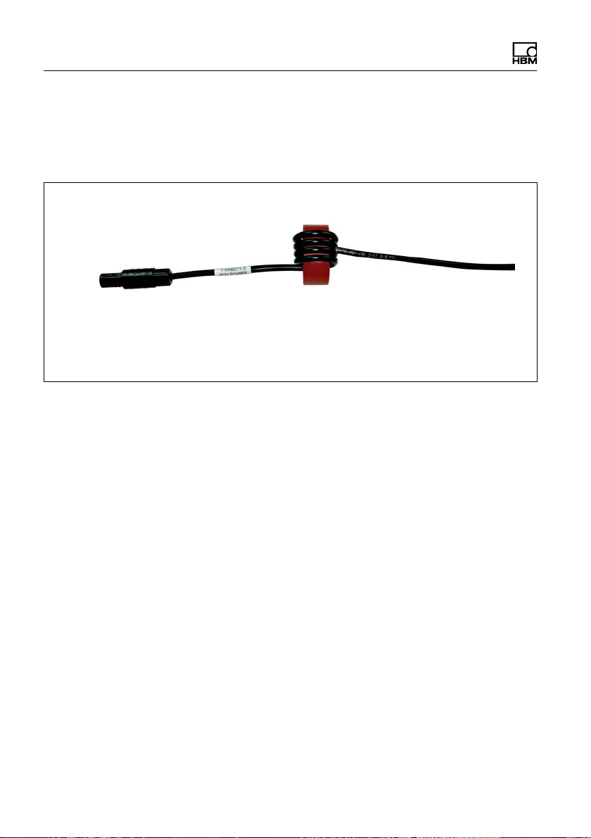
Electro magnetic conformity
(KAB271-3) around the inductive coil included in the
package four times.
ODU plug
When the NTX001 power supply from HBM is used, the
system complies with Emissions: Class B without the
necessity to carry out the meaasure described above.
16 I3031-14.0 HBM: public Quantum
X
Page 17
Markings used
3 Markings used
3.1 The markings used in this document
Important instructions for your safety are specifically
identified. It is essential to follow these instructions, in
order to prevent damage.
Symbol Meaning
Note
CAUTION
Important
Tip
Device -> New Bold text indicates menu items, as well as dialog and
Sampling rate, 500 Bold text in italics indicates inputs and input fields in
Emphasis
See …
This marking draws your attention to a situation in
which failure to comply with safety requirements may
lead to damage to property.
This marking warns of a potentially dangerous situ
ation in which failure to comply with safety require
ments may result in slight or moderate physical injury.
This marking draws your attention to important in
formation about the product or about handling the
product.
This marking indicates application tips or other in
formation that is useful to you.
window titles in the user interfaces. Arrows between
menu items indicate the sequence in which the
menus and sub-menus are opened.
the user interfaces.
Italics are used to emphasize and highlight text and
identify references to sections, diagrams, or external
documents and files.
Quantum
X
I3031-14.0 HBM: public 17
Page 18
Markings used
3.2 Symbols on the device
CE marking
CE marking enables the manufacturer to guarantee that
the product complies with the requirements of the
relevant EC directives (the Declaration of Conformity can
be found on the HBM website (www.hbm.com) under
HBMdoc).
Statutory waste disposal mark
In accordance with national and local environmental
protection and material recovery and recycling
regulations, old devices that can no longer be used must
be disposed of separately and not with normal household
garbage.
Electrostatically sensitive components
Components marked with this symbol can be damaged
beyond repair by electrostatic discharge. Please observe
the handling instructions for components exposed to the
risk of electrostatic discharge.
18 I3031-14.0 HBM: public Quantum
X
Page 19

4 Introduction
4.1 About the QuantumX documentation
The QuantumX family documentation consists of
S a printed quick start guide for initial start-up
S the data sheets in PDF format
S This operating manual in PDF format
S the operating manual for the EtherCAT®
S the operating manual for data recorder CX22B-W and
S the operating manual for the MX403B and MX809B
S the operating instructions for the Signal Conditioning
Introduction
1)
/ Ethernet
gateway CX27 in PDF format
CX22B data recorders
modules for safe measurement at high potential
Modules (SCM)
- High-voltage signal conditioned SCM-HV
(300 V CAT II)
- Quarter bridge adapter SCM-SG-120 / -350 for
connecting SGs individually
S the product descriptions for accessories
S a comprehensive online help with index and easy
search options which is available after the installation
of a software package (e.g. QuantumX Assistant, cat
man®EASY). Information about module and channel
configuration can also be found here.
These documents can be found
S on the QuantumX system CD supplied with the device
1)
EtherCAT® is a registered brand and patented technology, licensed by Beckhoff Automation
GmbH, Germany
Quantum
X
I3031-14.0 HBM: public 19
Page 20

Introduction
S After installation of the QuantumX Assistant on the
hard drive of your PC, which can be reached through
the Windows start menu
S Up-to date versions are always available from our In
ternet site at www.hbm.com/hbmdoc
4.2 The QuantumX family
The QuantumX family is a modular measurement system
for universal applications. The modules can be individu
ally combined and intelligently connected according to
the measurement task. Distributed operation makes it
possible to position individual modules close to the meas
uring points, resulting in short sensor lines.
The QuantumX family consists of the following
modules:
S MX840B Universal amplifier
The module has 8 universal inputs and supports more
than 15 transducer technologies.
S MX440B Universal amplifier
Like the MX840B, but with 4 inputs (connections 5-8
of MX840B, without CAN).
S MX410B Highly dynamic universal amplifier
The module has 4 universal inputs and supports com
monly used transducer technologies (at a sampling
rate of up to 96,000 measured values per channel per
second).
S MX430B QuantumX precision bridge measurement
module. The module has 4 inputs and supports full
bridge SG-based transducers with an accuracy class
of 100 ppm.
20 I3031-14.0 HBM: public Quantum
X
Page 21

Introduction
S MX238B Precision full bridge amplifier
The module has 2 full bridge SG inputs with an accu
racy of 25 ppm.
S MX460B Digital module (counter, frequency, timer)
The module has 4 individually configurable inputs for
connecting HBM torque measurement shafts (T12,
T40, T10), rotational speed sensors, crankshaft sen
sors with gap (TDC sensor), pulse width modulated
signals - PWM
S MX471B CAN module
The module has 4 CAN bus nodes that can be con
figured for receiving and sending messages. The
module supports the CCP and xCP-on-CAN protocols
on up to 2 channels.
S MX1601B Analog amplifier (standardized voltage /
current, IEPE)
The module has 16 individually configurable inputs for
standardized voltage or current measurement or for
connecting current-fed piezoelectric transducers
(IEPE / ICP(R) ).
S MX1615B SG bridge amplifier
The module has 16 individually configurable inputs for
SGs in quarter, half and full bridge circuits. Bridge
excitation voltage DC or carrier frequency (1200 Hz).
S MX1609KB Thermocouple amplifier
The module has 16 inputs for type K thermocouples.
S MX1609TB Thermocouple amplifier
The module has 16 inputs for type K thermocouples.
S MX809B Thermo measurement module
The module has 8 inputs for measurement of tempe
ratures with thermocouples or electrical cell voltages
up to 5 V at a potential up to 1000 V in energy storage
systems. General measurement categories: 600 V
CAT II, 300 V CAT III.
The module and entire production have been certified
Quantum
X
I3031-14.0 HBM: public 21
Page 22

Introduction
by VDE, and stand for maximum safety when working
with dangerous voltages.
S MX403B voltage module
The module has 4 inputs with lab connectors for
voltage measurement (1000 V CAT II, 600 V CAT III).
The module and entire production have been certified
by VDE, and stand for maximum safety when working
with dangerous voltages.
Notice
When using the modules MX403B or MX809B, please
refer to the separate operating manual, document num
ber A3757.
S CX22B or CX22B-W (WLAN) Data recorder
The module is used for local recording of measure
ment data.
S CX27B EtherCAT®/Ethernet gateway
The module is used to connect QuantumX modules to
the EtherCAT® fieldbus or the Ethernet.
S MX878B Analog output module
The module has 8 scalable voltage outputs ("10 V)
that can be assigned with a system signal or a source
signal. Signals can also be calculated in real time.
S MX879B Multi‐I/O module
The module has 8 scalable voltage outputs and 32
configurable digital inputs/outputs. Signals can also be
calculated in real time.
All modules have the following in common:
S Supply voltage range 10 … 30 V DC (nominal rated
voltage 24 V DC)
22 I3031-14.0 HBM: public Quantum
X
Page 23

Introduction
S Configurable Ethernet interface for data communica
tion with an operating PC
S 2 IEEE1394b FireWire interfaces
- For optional voltage supply
- For optional data communication with a PC
- For automatic time synchronization of the modules
- For real-time transfer of measurement data
between the modules
S Connector for installation on a backplane (not applic
able for ultra-robust variants)
S Status LEDs for displaying general system and chan
nel states
S A factory calibration certificate is stored on each amp
lifier, which can be read by the QuantumX Assistant.
S AutoBoot (module configurations are retained)
With amplifiers, the following applies for each
measurement channel:
S Galvanic isolation (signal inputs/outputs, voltage sup
ply, communication)
S Configurable supply voltage for active sensors
S Support for TEDS2) technology (read, write)
S Configurable sampling rate
S Configurable digital filter (Bessel, Butterworth)
S configurable scaling
Sensors assigned using the sensor database can be cal
ibrated via the channel and written back into the sensor
database.
2)
TEDS = Transducer Electronic Data Sheet
Quantum
X
I3031-14.0 HBM: public 23
Page 24
Introduction
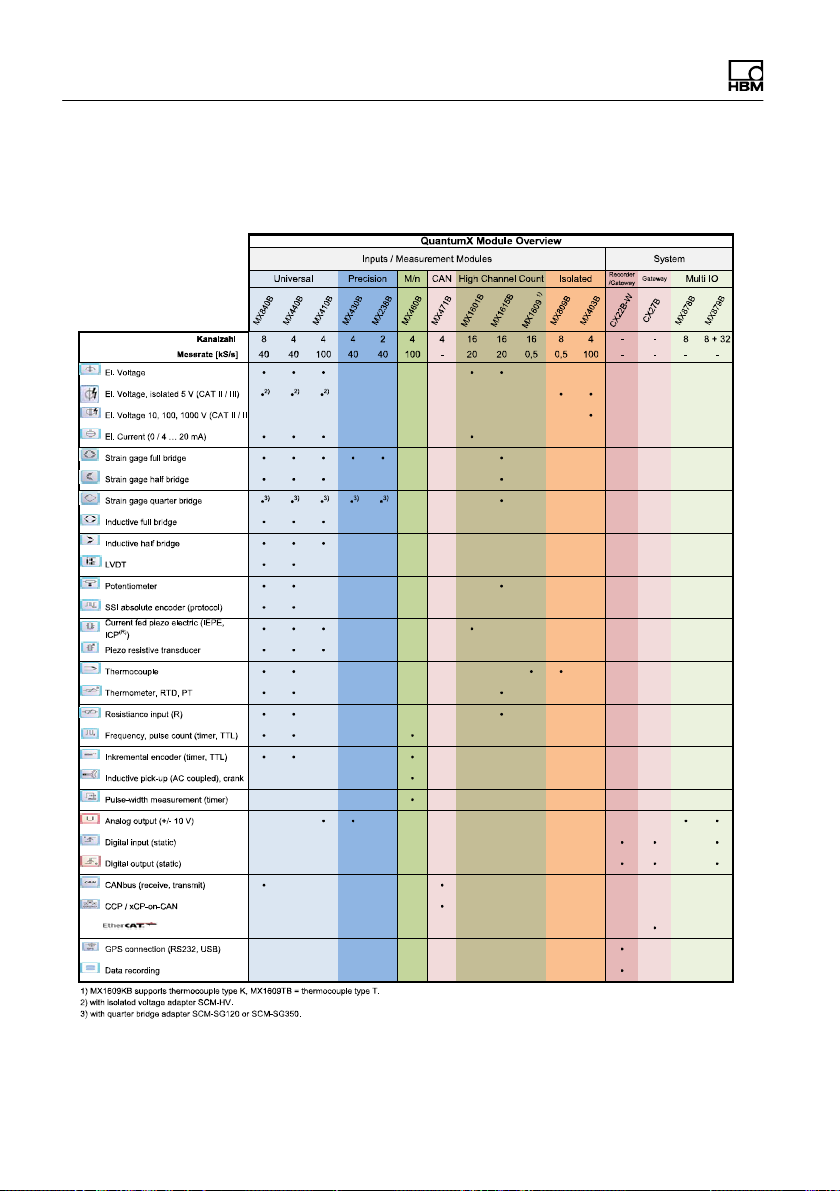
4.3 Module overview/transducer technologies
24 I3031-14.0 HBM: public Quantum
X
Page 25

Introduction
See data sheets for precise technical specifications. The
pin assignments can be found in the following chapters.
4.4 Digitalization and signal path
Data rate
QuantumX measurement modules with the suffix B, like
the MX840B, for instance, have decimal data rates such
as 600, 1200, ....19,200 S/sec available, in addition to
classic data rates such as 500, 1000, .... 100,000 S/sec.
When there are several modules in a group, the selected
data rate domains must be identical. Catman® or MX
Assistent software allows toggling the sample rate do
main, e.g. From „Classic“ to „Decimal“.
Signal paths
Synchronizing the acquisition of all channels allows sig
nal analysis of all recorded measurement data at the
same time.
Quantum
It often happens that some sensor signals should be
made available in real time, in parallel with the data ana
lysis of highfrequency signals (e.g. 100 kS/sec per chan
nel), i.e. deterministically, with a moderate data rate (e.g.
1 kS/sec or 1 ms control loop) and with a minimum
latency time (e.g. max. 1 ms).
To do this, the modules need to be connected with each
other via the FireWire bus and the signals need to be
made available "isochronously", for example, to be com
puted and/or output via another module (analog, CAN,
EtherCAT).
To give this parallel operation optimum support, each
QuantumX measurement channel generates two signals.
X
I3031-14.0 HBM: public 25
Page 26

Introduction
The maximum isochronous data rate per channel is ap
prox. 5 kS/sec (125 μs clock pulse on the FireWire bus).
Scaling
QuantumX supports the following types of scaling:
S Two points (2‐point / y=mx+b)
S Table (multi-point) supported from MX840B, MX440B,
MX1609/KB/TB, MX809B
S Polynomial, supported from MX840B, MX440B,
MX440B, MX430B, MX238B
The 16-channel modules (MX1601B and MX1615B) as
well as modules MX410B and MX460B only support twopoint scaling.
4.5 Synchronization
If measurement signals need to be referenced over time
with each other for processing and analysis, they must
be recorded synchronously.
All QuantumX modules can be synchronized among
themselves. This ensures simultaneous measurement on
all channels. All the analog-digital converter rates, meas
uring rates and bridge excitation voltages are therefore
also synchronized.
Synchronization methods:
Synchronisation via Ethernet IEEE1588:2008 (PTPv2)
When modules, for example, MX840B are set to this syn
chronization mode and z.B. untereinander mit einem
PTP-fähigen Switch connected using a switch with PTP
capability, they automatically synchronize with each other
26 I3031-14.0 HBM: public Quantum
X
Page 27

Introduction
or a Grandmaster Clock. Transparent Clock (TC) mode
is supported here.
The following setup parameters are available:
S Time delay: End2End (E2E) or Peer2Peer (P2P)
S Transport protocol: IPv4 or IPv6
Modules that do not support this mode, such as MX840A
can be connected via FireWire to the adjacent module
with PTPv2, and included in the synchronization (auto
matic clock distribution).
The converted modules must be restarted. The system
as a whole therefore supports the classic HBM sample
rates only.
Converted modules need to be restarted. After restart,
check the system LEDs at the module front green
means synchronous.
Synchronization via IEEE1394b FireWire
All the modules are synchronized automatically when
they are connected via the IEEE1394b FireWire cable.
This is the recommended method.
Quantum
No CX27/B module present in the system and no exter
nal synchronization source available:
The module with the highest serial number (UUID) takes
over the master function.
CX27/B module present in the system and no external
synchronization source available:
If a CX27/B module is connected, it automatically
becomes the synchronization master. When starting the
system, the system time is set once to the actual time.
If QuantumX modules alone are being used, internal syn
chronization is sufficient. However, if synchronous mea
X
I3031-14.0 HBM: public 27
Page 28

Introduction
surements are to be performed by different measurement
systems, an external master must be used for synchro
nization.
This is also a requirement if the QuantumX modules are
a long distance away from one another and an
IEEE1394b FireWire connection would be too complex.
Synchronization with external sources
In an external synchronization source is set, the module
with the best synchronization quality automatically
becomes the master and synchronizes all modules con
nected via IEEE1394b FireWire.
If several external sources are selected, the system
decides according to the following priorities:
1. EtherCAT®
2. IRIG-B
3. NTP
Synchronization via EtherCAT®
The CX27 gateway supports the “Distributed Clocks”
expansion of EtherCAT®. The time is distributed to all
EtherCAT® nodes in an EtherCAT® group.
The CX27 module can be synchronized to the Ether
CAT® time. This will mean that all the QuantumX module
clocks are synchronized to this time.
Synchronization via an NTP server
Each QuantumX module can synchronize its internal
clock with an NTP server. The NTP time is distributed to
the other modules via IEEE1394b FireWire.
28 I3031-14.0 HBM: public Quantum
X
Page 29

Introduction
It is possible to achieve accuracies of 1 ms or higher,
depending on the utilization of the network and on
whether or not a dedicated NTP master is being used.
Modules located close together should be synchronized
via IEEE1394b FireWire.
If the synchronization source for a module is changed to
NTP, the system must be restarted once. The HBM cat
man®EASY software includes an NTP software pack
age.
Parameter:
S IP address of the NTP server
S Threshold in s below which the time deviation to
NTP time is tolerated
Further information about NTP can be found at
http://www.ntp.org
Synchronization via IRIG-B
IRIG-B is a standardized time coding.
Quantum
To time-synchronize the QuantumX system, the digital or
analog modulated time signal is sent externally to any
analog voltage input of the amplifier type MX840B or
MX440B (see Assignment, section 8.2.1).
The B127 format uses analog modulation. Connection is
identical to that of a 10-V voltage sensor.
The other formats are BCD‐coded and must be con
nected analog to the sensor "Frequencies single-pole,
without directional signal", see section 9.29.
The amplifiers can record IRIG‐B signals of type B000 to
B007 and B120 to B127. All modules connected via
IEEE1394b FireWire are also automatically synchro
X
I3031-14.0 HBM: public 29
Page 30

Introduction
nized. The coding includes the time, year and optionally
the seconds of the day.
Comparison of synchronization mechanisms
Feature IEEE1394b
FireWire
Synchroniza
tion with
other device
types
Max. dis
tance
between
QuantumX
modules
Number of
modules to
be synchron
ized
Synchroniza
tion accuracy
Synchroniza
tion settling
time
QuantumX
only
5 m (40 m
with
IEEE1394b
FireWire ex
tender,
500 m via
optical fiber)
< 1 s < 1 s
Immediate Up to 20 s
Ethernet
(PTPv2)
QuantumX
B module
GENESIS
Cameras
100 m elec
trical and up
to a few
100 m opti
cal
24 Unlimited Unlimited CX27 re
(with recom
mended
PTPv2
switches up
to 100 ns)
(on initial
startup)
Ethernet
(NTP)
QuantumX,
MGCplus
other
interrogators
100 m elec
trical, several
km optical,
variable with
WLAN
100 s to 10
ms
Up to 30 min
during first
start, up to
2 min during
restart
EtherCAT® IRIG-B
All
EtherCAT®
nodes
100 m -
quired, un
limited
< 1 s < 1 s
Immediate Immediate
All IRIG-B
nodes
Unlimited
MX440B,
MX840B
required,
30 I3031-14.0 HBM: public Quantum
X
Page 31

Introduction
Feature
Synchroniza
tion
master
Voltage sup
ply
IEEE1394b
FireWire
Auto
1 QuantumX
module
< 1.5 A,
looped
through
Ethernet
(PTPv2)
Auto oder
Grandmas
ter‐
Clock
- - - -
(NTP)
External Syn
cMaster ,
e.g. PC
External
SyncMaster
IRIG-BEtherCAT®Ethernet
External
IRIG-B
master
Quantum
X
I3031-14.0 HBM: public 31
Page 32

Introduction
Synchronization via IEEE1394b FireWire
Auto
Auto
Auto
Auto
Synchronizing via CX27B (EtherCAT®)
Auto
Auto
Auto
CX27B
Synchronizing via Ethernet / NTP and Gateway CX27B
(IEEE1394b FireWire to the modules)
Auto
Auto
Auto
NTP
*)
Time base:
Automatic
(factory setting)
Time base:
EtherCAT® master
EtherCAT®
Time base:
NTP server
Ethernet
Synchronizing via Ethernet / NTP (without IEEE1394b FireWire)
NTP
NTP
NTP
NTP
Time base:
NTP server
Ethernet
switch
*)
CX27 or the module with the highest serial number
32 I3031-14.0 HBM: public Quantum
X
Page 33

Synchronzing via Ethernet PTPv2 (IEEE1588:2008)
PTP
Fig. 4.1 Different methods of time synchronization
PTP
PTP
Additional information on the subject of
"synchronized"
To achieve a precise reference over time, the applicable
channels must be parameterized with the same filter set
tings. No automatic runtime correction is carried out. The
filter runtimes are shown in the data sheet. After booting
and successful synchronization, the system LED is lit
green. If synchronization is disturbed, or not yet estab
lished, the system LED is lit orange.
Introduction
PTP
EthernetPTPv2Switch
Quantum
X
I3031-14.0 HBM: public 33
Page 34

Introduction
Example: MX840B
Time format used
Basis: 1.1.2000
Time stamp: 64 bit
32 bit seconds
32 bit fractions of a second,
resolution (1/232)
These time stamps are appended to the measured val
ues.
There are several synchronization methods to choose
from (also see Fig. 4.1 page 33):
S Synchronization via IEEE1394b FireWire
S Synchronization via EtherCAT® (CX27)
S Synchronization via NTP (Network Time Protocol)
with IEEE1394b FireWire
S Synchronization via NTP without IEEE1394b FireWire
34 I3031-14.0 HBM: public Quantum
X
Page 35

5 Software
Software
QuantumX is an "open" measurement system, and can
be integrated into a great many operating, analysis and
automation software packages.
The following powerful packages are available to down
load:
- MX Assistant: a modern and free device or system
assistant that supports all the module functions
- catman®Easy / AP / Enterprise: the powerful, pro
fessional software for acquiring measurement data
from 4 up to 20,000 channels
- Drivers for LabVIEW, Visual Studio .NET, CANape,
DIAdem, etc.
- Windows device driver for IEEE1394b FireWire
5.1 MX Assistant
Quantum
The HBM "QuantumX Assistant" software offers the fol
lowing functions:
System:
S Create overview (modules, host PC)
Modules:
S Data rate domain adjustment (decimal, classical
HBM)
S Time synchronization adjustment
S Search and configuration (e.g. TCP/IP communica
tion), naming
S Reset to factory settings
S Read working standard calibration certificate
X
I3031-14.0 HBM: public 35
Page 36

Software
S Analysis (information, status, log file)
S Save configuration to operating PC
Channels/sensors:
S Configuration (name, connection type, TEDS, semi-
automatic assignment)
S Measurement
S Activate/deactivate isochronous operation via
IEEE1394b FireWire
Individual signals:
S Set sampling rates and filters (type, cut-off frequency)
Measured values (scope):
S Start/stop continuous graphic measurements (time
frames, trigger, zoom)
S Basic signal analysis (X/Y cursor)
S Record measurements
Functions and outputs:
S Map inputs to outputs (scaled, filtered)
S Real-time function parameterization (RMS value,
addition, multiplication), torsional vibration analysis,
limit value monitoring, matrix calculation, PID con
troller
S Map signals to CAN messages (data types) and gene
rate CANdb (*.dbc)
Sensor database
S Write sensor data sheets to TEDS
S Add user-defined sensor data sheets, import CANdb
(*.dbc)
36 I3031-14.0 HBM: public Quantum
X
Page 37

Software
5.2 catman®AP
The HBM "catman®AP" software is optimally suited for
the following tasks:
S Setting the communication and measurement chan
nels (integrated TEDS editor and extendable sensor
database)
S Configuration of measurement or test tasks (chan
nels, sampling rates, triggers, comments, interactions)
S Setting up virtual online calculated channels (algebra,
FFT, logic, SG rosette evaluation, differential, integral,
etc.)
S Setting up limit value or event monitoring (digital out
put activation, acoustic alarm, logbook entry)
S Individual graphic representation options (strip chart,
analog meter, digital or bar display, tables,
2D frequency spectrum, geographical maps, status
LED, etc.)
S Signal visualization in time, frequency or angular reali
zation
Quantum
S Diverse storage options (all data, cyclic, ring buffer,
long-term measurements, etc.)
S Maximum data throughput of 12 MS/s or 100 Mbyte/s
S Export of measured data in current data format (cat
man®BIN, Excel, ASCII, MDF, MAT, DIAdem, UFF)
S Graphical post‐process analysis of recorded data,
data cleansing and export to different formats.
S Automation of measurement sequences (Auto
Sequence and EasyScript)
S Generating reports (with graphic displays, analyses,
comments)
X
I3031-14.0 HBM: public 37
Page 38

Software
The software package catman®AP consists of various
modules:
S catmanEASY
measurement and virtual channels, visualization and
storing measurement data with integrated sensor
database and TEDS
S EasyRoadload includes Ethernet drivers for Kistler
RoaDyn® measuring wheels, EasyVideocam, geo
graphical maps, importing a channel parameter list
from Microsoft Excel.
S EasyVideocam Integration of up to 4 video cameras
(generally Windows DirectShow, USB / Ethernet /
FireWire)
S EasyPlan allows for preparatory parameterization and
configuration without an amplifier connected using a
wizard or tables with Microsoft EXCEL®
S EasyScript is based on the current VBA standard
(Visual Basic for Applications) and allows users to
write their own scripts for individual measurement
tasks
S EasyMath
and export of measurement data
– the basic package for recording
allows mathematical postprocess analysis
5.3 LabVIEW® driver / library
LabVIEW is a graphical programming system from Na
tional Instruments. The acronym stands for “Laboratory
Virtual Instrumentation Engineering Workbench”.
The main application areas for LabVIEW are in measure
ment, control and automation technology.
38 I3031-14.0 HBM: public Quantum
X
Page 39

Software
LabVIEW modules are virtual instruments (VIs) or subprograms that are used in LabVIEW programs for con
venient device control. The library components are used
to initialize, open and close interfaces, to initialize and
configure the modules, to make settings, and to trigger
and query measurements.
The HBM LabVIEW driver is based on the HBM com
mon.NET API. The installation includes some examples
and extensive help.
5.4 Driver for Microsoft® Visual Studio .NET
The HBM Common API can be understood as a generic
application programming interface (API), and integrates
QuantumX into the powerful programming environment
of Microsoft Visual Studio .NET. Programmers can use
APIs to directly access almost all QuantumX device func
tions and use them in their own programs.
Quantum
Functions such as communication connection, configura
tion of measurement channels, implementation of meas
urements and troubleshooting are components of the
library.
This package can be downloaded free from hbm.com.
There are applicationbased examples and practical doc
umentation to help you get started quickly.
5.5 Other drivers
QuantumX is an open data acquisition system and there
fore has been integrated into many software packages.
Here are some examples:
X
I3031-14.0 HBM: public 39
Page 40

Software
S DIAdem
S CANape
S DASYLab
S Mlab
S InNova
5.6 Firmware update via Ethernet
You can easily check the firmware status of the modules
and update them when necessary with the "MX Assis
tent" software or catman
Before updating your firmware, check whether your PC
software needs updating first.
We recommend checking the firmware and updating it as
needed:
S If you want to use a new PC software package
S If you want to expand your system with new modules
®
.
You can also determine the firmware status of your mod
ules using the QuantumX Assistant:
S Rightclick on the computer in the device overview
*> Details *> System overview
40 I3031-14.0 HBM: public Quantum
X
Page 41

6 Mechanical
QuantumX modules are extensively tested. This includes
The degree of protection given in the technical data indic
ates the suitability of the housings for various ambient
conditions and also the protection of persons against po
tential risks when used. The letters IP (International Pro
tection), which are always present in the designation, are
followed by two digits. These indicate which degree of
protection a housing offers against contact or foreign
bodies (first digit) and moisture (second digit).
QuantumX modules are in a housing with IP20 as degree
of protection.
Mechanical
- the extended temperature range
- mechanical vibration with an amplitude of 50 m/s²
in the frequency range 5 ... 2000 Hz in all 3 axes
for 2 hours, and
- the effect of exposure to 1000-fold mechanical
shock with an acceleration (half cosine) of 350 m/s²
for 3 ms in all 3 axes.
IP 2 0
Code
index
2 Protection against contact with
Degree of protection against
contact and foreign bodies
fingers, protection against for
eign substances with >12
mm
Both housing types can be connected together with the
aid of two lateral housing clips (1-CASECLIP, not in
Quantum
X
I3031-14.0 HBM: public 41
Code
index
0 No water protection
Degree of protection against
water
Page 42

Mechanical
cluded in scope of delivery). To do this, the existing lat
eral covers must be removed and the housing clips
screwed on.
6.1 Mounting case clips on modules
The module electronics are integrated in a metal housing
that is surrounded by a case protection (CASEPROT).
This also serves for centering when several devices are
stacked on top of each other and offers a certain degree
of protection against mechanical damage.
Case protection
MX840 housing
Cover
Fig. 6.1 Amplifier MX840 with case protection
The mounting of the housing clips shown in the following
pictures must be implemented on both sides of the hous
ing.
42 I3031-14.0 HBM: public Quantum
X
Page 43

2.5 a.f.
Mechanical
Fig. 6.2 Removing the case protection
Quantum
Cover
Fig. 6.3 Removing the cover
X
I3031-14.0 HBM: public 43
Page 44

Mechanical
Case clip
2.5 a.f.
Fig. 6.4 Mounting the case clip CASECLIP
2.5 a.f.
Fig. 6.5 Mounting the case protection CASEPROT
44 I3031-14.0 HBM: public Quantum
X
Page 45

Mechanical
6.2 Connecting housings
The following pictures show the connection of two hous
ings.
Press
Fig. 6.6 Unclip the case clip CASECLIP
Quantum
Lever
Catch
Fig. 6.7 Unclip the lever and catch
X
I3031-14.0 HBM: public 45
Page 46

Mechanical
Fig. 6.8 Close the lever
Fig. 6.9 Connected housings
46 I3031-14.0 HBM: public Quantum
X
Page 47

Mechanical
6.3 Mounting the housing with CASEFIT
A CASEFIT fitting panel can be used for flexible mount
ing of QuantumX series modules. The modules can be
fastened in place with belt tensioners or case clips
(CASECLIP).
132
Lugs for additional
fastening with
tension belts
Dimensions in mm (1 mm = 0.03937 inches)
Fig. 6.10 Mounting with CASEFIT and CASECLIP
6.4 BPX001/BPX002 backplane
The use of a backplane such as BPX001 or BPX002
(RACK) allows up to 9 modules to be connected with
hardly any wiring.
The backplane also has two additional FireWire inter
faces for integrating distributed modules or for direct con
nection to a PC or data recorder. The IEEE1394b
FireWire interfaces are actively interconnected.
Quantum
X
I3031-14.0 HBM: public 47
11.4
22
169.5
Ø 5.6
approx. 30
Page 48

Mechanical
The individual modules can also be connected via Ether
net (RJ45) through the openings on the back of the back
plane. FireWire interfaces of the individual modules are
actively connected to each other.
The modules can be positioned anywhere in the back
plane. The backplane BPX001 is designed for wall or
control cabinet installation and has drill holes for attach
ment. The BPX002 backplane for rack mounting in a 19”
enclosure. The BPX002 backplane is an extension of the
BPX001.
Slot 9
Slot 1
Fig. 6.11 Example of QuantumX backplane fitting
48 I3031-14.0 HBM: public Quantum
X
Page 49

IEEE1394b FireWire
(PC, external modules)
Fuses with
control LEDs
4 x 4 A/T
Supply voltage
18 V ... 30 V DC
5 A max.
6.4.1 Connection
X1 / X2
+
-
Mechanical
VG strip
Module
connection
Quantum
X
Grounding
Fig. 6.12 BPX001 connections
I3031-14.0 HBM: public 49
Page 50

Mechanical
Fuse Protects
1 IEEE1394b FireWire X1 connection
2 IEEE1394b FireWire X2 connection
3 Slots 1 to 4
4 Slots 5 to 9
6.4.2 Backplane BPX001
A total of 10 drill holes are provided in the backplane for
wall mounting ( 6.5 mm). We recommend using the
outer 4 drill holes for wall mounting.
Notice
Only use countersunk screws for fastening. Otherwise
the modules cannot be mounted correctly.
449
220
6.5
85
56.75
140.75
318.75
229.75
407.75
147.5
36.25
Fig. 6.13 BPX001 drilling pattern and dimensions
50 I3031-14.0 HBM: public Quantum
X
Page 51

Mechanical
Note the following information when installing one or
more backplanes in a control cabinet:
S When installing in a control cabinet, the temperature
limits given in the technical data of the backplanes
must be complied with
S Depending on the installation situation, sufficient vent
ilation (vertical air flow) or cooling must be provided
(the maximum total output on a backplane is approx.
150 watts)
S The ventilation slots of the modules must not be
covered (by cable ducts, etc.)
Quantum
X
I3031-14.0 HBM: public 51
Page 52

Mechanical
6.4.3 Backplane BPX002
482.6
470
448.5
462
146.05
165.3
214.5
220.9
0
131
65.5
32.75
98.25
Fig. 6.14 Rackmontage BPX002
6.4.4 Mounting the modules
Tools
We recommend a T-handle Allen wrench 4x150 (4 mm
across flats, length 150 mm).
52 I3031-14.0 HBM: public Quantum
X
Page 53

Mechanical
Notice
The modules can only be fastened in backplanes in
housings with degree of protection IP20 without case
protection, case clips or lateral covers. If these are
present, remove as shown in section 6.
Mounting sequence:
1. Remove the cover of the connecting plug (rear of
module).
Cover
Quantum
Fig. 6.15 Removing the cover
2. Unscrew the upper and lower screwed clamping
glands of the backplane up to the stop (the screws
are secured against falling out!).
3. Position the module vertically on the backplane and
push it in carefully on the lower guide rail back up to
the stop.
X
I3031-14.0 HBM: public 53
Page 54

Mechanical
Upper screwed clamping gland
4,0 a.f.
Opening for con
nection to Ethernet
Lower screwed clamping gland
Fig. 6.16 Mounting the module
Fig. 6.17 Centering above the connection plug
Guide rails
54 I3031-14.0 HBM: public Quantum
X
Page 55

Mechanical
4. Tighten the lower then the upper screwed clamping
gland.
2.
1.
Fig. 6.18 Tightening the screwed clamping glands, sequence
Quantum
X
I3031-14.0 HBM: public 55
Page 56

Mechanical
6.4.5 Backplane with Ethernet connection
A central CX27B gateway enables a BPX backplane to
be connected. Maximum sampling rate: 400 kS/s.
The IEEE1394b FireWire sockets on the backplane allow
integration of distributed modules into the system.
The individual modules can also be connected directly
via Ethernet on the back, with maximum sampling rate.
In this case, no gateway is required.
BPX001 + CX27
Fig. 6.19 Connecting a backplane via Ethernet
56 I3031-14.0 HBM: public Quantum
X
Page 57

Mechanical
6.4.6 Backplane with IEEE1394b FireWire
connection
The BPX backplane can be connected via IEEE1394b
FireWire directly to a PC or data recorder.
The second IEEE1394b FireWire socket on the back
plane can be used to integrate distributed modules into
the system.
FireWire
Fig. 6.20 Connecting a backplane via IEEE1394b FireWire
KAB293-5
BPX001
Quantum
X
I3031-14.0 HBM: public 57
Page 58

Mechanical
6.4.7 System layout with several backplanes
Multiple BPX backplanes can be synchronized via CX27
gateway modules. Connection of CX27 to CX27 via
KAB2722 or 5, via front IEEE1394b FireWire connec
tion.
Fig. 6.21 Synchronizing multiple backplanes
58 I3031-14.0 HBM: public Quantum
X
Page 59

Connecting individual QuantumX modules
7 Connecting individual QuantumX modules
7.1 Connecting the supply voltage
Connect the modules to a DC voltage of 10 V ... 30 V
(24V recommended). The power consumption per device
can be found in the following table.
CAUTION
The following rule of thumb applies to power distribution
via FireWire:
“An external voltage supply with the same voltage poten
tial is required on every 3rd module“.
Defects in the module cannot be excluded if a supply
voltage > 30 V is used. If the supply voltage drops below
10 V, the modules switch off.
Quantum
We recommend installing an uninterruptible power supply
(UPS) in vehicles with battery operation between battery
and module to compensate for voltage drops during start
procedures.
Module Typical power consumption, including
transducer excitation (watts)
MX840B 12
MX440B 10
MX410B 15
MX430B 8
MX238B 8
MX460B 9
X
I3031-14.0 HBM: public 59
Page 60

Connecting individual QuantumX modules
Module
MX471B 6
MX1601B 13
MX1615B 12
MX1609/KB/TB 6
MX809B 6
CX22B-W/
CX22B
CX27B 7
MX878B 7
MX879B 7
Typical power consumption, including
transducer excitation (watts)
12
If several modules are connected to each other via
FireWire for time-synchronous data acquisition (see
Fig. 7.4), the supply voltage can be looped through. The
power pack used must be able to provide the appropriate
output.
The maximum permissible current on the IEEE1394b
FireWire connection cable is 1.5 A. If the chain is longer,
repeating the supply connection is mandatory.
If several amplifiers are operated non-synchronously (see
Fig. 7.3), they must be supplied separately.
60 I3031-14.0 HBM: public Quantum
X
Page 61

Connecting individual QuantumX modules
NTX001
Or
1-Kab271-3
1-KAB272
FireWire
X104
X101/X102
Fig. 7.1 Connecting socket for supply voltage
Quantum
X
I3031-14.0 HBM: public 61
Page 62

Connecting individual QuantumX modules
7.2 Connection to host PC or data recorder
7.2.1 Single Ethernet connection
10 V ... 30 V DC
1-NTX001 or
1-KAB271-3
TCP/IP, 100 Mbps
KAB293-2
Fig. 7.2 Single Ethernet connection
X104
X100
Notice
You must use an Ethernet crossover cable with older
computers. Newer PCs/laptops have Ethernet interfaces
with autocrossing function. You can also use Ethernet
patch cables for this purpose.
62 I3031-14.0 HBM: public Quantum
X
Page 63

Connecting individual QuantumX modules
7.2.2 Multiple Ethernet connection with PTP synchronization
10 V ...
30 V DC
10 V ...
30 V DC
10 V ...
30 V DC
Patch cable
PTPv2‐Switch
Patch cable
Ethernet
Fig. 7.3 Multiple connection via Ethernet and synchronization
via PTPv2
Modules can be connected to the PC via Ethernet
PTPv2‐compliant switches. We recommend patch
cables.
Here are some examples:
- EX23-R from HBM
- Scalance XR324-12M from Siemens
- RSP20 or MACH1000 from Hirschmann
- Ha-VIS FTS 3100-PTP from Harting
- Stratix 5400 from Rockwell
Quantum
PTP Grandmaster Clock examples:
- LANTIME M600 from Meinberg
- OTMC 100 from Omicron
X
I3031-14.0 HBM: public 63
Page 64

Connecting individual QuantumX modules
With the star structure displayed here, measurement
data from other modules is not lost if the Ethernet cable
is broken!
7.2.3 Multiple Ethernet connection and FireWire synchronization
10 V ... 30 V DC
Patch cable
Standard Ethernet‐Switch
TCP/IP, 100 Mbps
Patch cable
FireWire connection
1-KAB272-x: Connection cable with various lengths (x m)
Basic rule: X102 -> X01 -> X102… to acceptor (PC, data recorder)
Fig. 7.4 Example of multiple connection via Ethernet with
synchronization
The supply voltage for the modules is looped through
FireWire in the configuration shown above (max. 1.5 A
through FireWire; for power consumption of the modules,
see Chapter 7).
64 I3031-14.0 HBM: public Quantum
X
Page 65

Connecting individual QuantumX modules
Advantage of this connection structure: The other mod
ules remain active if the Ethernet cable is broken.
7.2.4 Connecting one or more QuantumX modules to the PC
Modules can be connected to a standard PC via Ethernet
(up to 100 m), via FireWire (electrically, up to 5 m, opti
cally up to 300 m), or via EtherCAT.
The following must be noted for TCP/IP communication
via Ethernet:
S We recommend that you retain the default setting
(DHCP/APIPA), so that the software can find the
modules that are in the network, or directly connec
ted. You can, of course, also parameterize the mod
ules with a fixed, static IP address. This also applies
to the PC or notebook. Advantage: this allows note
books in particular to be quickly and automatically in
tegrated without reconfiguration into the company
network (DHCP). But direct operation between the
notebook and the modules (peer2peer) is also very
quick, using automatic addressing (APIPA).
Quantum
S The Ethernet network adapter of the PC or modules
can also be manually configured with a specific IP
address and subnet mask, of course.
The following must be noted for direct IPoverFireWire
via FireWire connection:
S FireWire adapter addressing (e.g. expressCard/34 or
PCIexpress) at the PC or data logger end uses a pre
viously installed Windows device driver from HBM,
and cannot be modified. The modules are automatic
ally addressed (plugandplay and USB), and are
available immediately.
X
I3031-14.0 HBM: public 65
Page 66

Connecting individual QuantumX modules
Notice
The network connection can be influenced by:
S An activated WiFi connection on your PC: Switch off
this connection, if necessary, and restart the network
search.
S The relevant scan ports not being enabled in the fire
wall settings of your PC.
66 I3031-14.0 HBM: public Quantum
X
Page 67

Recommended
Connecting individual QuantumX modules
To configure the IP address of the module:
S Activate DHCP/APIPA for automatic configuration.
Please set any PC directly connected to QuantumX to
DHCP as well.
Quantum
S Manual configuration: Deactivate DHCP and enter the
same subnet mask address as used with your PC.
Change the IP address of your module so that it
permits communication (see example below)
X
I3031-14.0 HBM: public 67
Page 68

Connecting individual QuantumX modules
Example:
Setting the IP address manually – module side
Settings IP address Subnet mask
Module before 169.1.1.22 255.255.255.0
PC / notebook 172.21.108.51 255.255.248.0
Module after 172.21.108.1 255.255.248.0
The first three digit groups of the PC and module IP
addresses should be the same.
The subnet mask address digit groups must be identical
in the module and PC!
68 I3031-14.0 HBM: public Quantum
X
Page 69

Automatic
configuration
Module settings
PC settings
Connecting individual QuantumX modules
Module settings
Manual
configuration
PC settings
Quantum
172.21.108.1
255.255.248.0
Fig. 7.5 Example of settings for a direct connection
X
I3031-14.0 HBM: public 69
Page 70

Connecting individual QuantumX modules
Ethernet settings: adjust the IP address of your PC
If you want to operate the modules with a fixed, static IP
address, you should use the "Alternative Configuration"
(fixed IP address and subnet mask, userdefined) in the
Ethernet adapter properties under TCP/IP the ”Alternat
ive Configuration” in the TCP/IP properties (fixed IP ad
dress and subnet mask, user-defined)!
Edit the PCs settings as follows:
S Open the network connections (Start/Settings/Net
work connections).
S Mark your LAN connection with a right-click and select
“Properties” in the context menu.
S Select the
uses the following items” mark Internet (TCP/IP).
Click on the “Properties” button.
70 I3031-14.0 HBM: public Quantum
“General” tab and under“This connection
X
Page 71

Connecting individual QuantumX modules
S On the “Alternate Configuration” tab, select the
“User-defined” option and enter your data in the “IP
address” and “Subnet mask” lines.
Example:
Setting the IP address manually – PC side
Settings IP address Subnet mask
Module before 169.1.1.22 255.255.255.0
PC / notebook before 172.21.108.51 255.255.248.0
PC / notebook after 169.1.1.1 255.255.255.0
Quantum
X
I3031-14.0 HBM: public 71
Page 72

Connecting individual QuantumX modules
S Confirm twice with “OK”.
In future your computer will use the “Alternative Config
uration” for the direct connection.
Integrating modules in an Ethernet network
S Activate the DHCP checkbox and click on“OK”. The
following confirmation window then appears:
S Confirm the settings with the“Yes” button. The
module will then be restarted with the current settings.
72 I3031-14.0 HBM: public Quantum
X
Page 73

Connecting individual QuantumX modules
7.2.5 Firmware update via Ethernet
We recommend that the firmware and software used to
operate QuantumX are always kept up to date.
S Download the latest firmware from the HBM website.
If you do not work with catman®, please download the
QuantumX software package from the HBM website.
Please save the firmware under ...\HBM\cat
manEasy\Firmware\QuantumXB, or on C:\Temp.
S Start catman®, scan the network for modules and
carry out the recommended firmware update. catman
comes with the firmware included. This is usually
stored under:
C:\Program Files\HBM\catman\Firmware\Quan
tumXB
If you do not work with catman®, please install the
free MX Assistant, connect to the modules, and use it
to perform the update. If the modules have a firmware
version < 2.21, you should install the QuantumX Firm
ware Updater tool, and use it to bring all the modules
up to date. From firmware version > 4.0, a firmware
update can also be performed with the MX Assistant,
or with catman.
Quantum
X
I3031-14.0 HBM: public 73
Page 74

Connecting individual QuantumX modules
Notice
You can update the firmware of the modules directly via
Ethernet, or via the CX27 gateway. You must never dis
connect the data link while the update process is running.
7.2.6 Connection via FireWire (IEEE 1394b)
General information
S Baud rate of 400 MBaud (approx. 50 MByte/s)
S Asynchronous (all nodes) or isochronous (in real time)
data transmission
S Data synchronization
S Supply voltage via FireWire connection cable (max.
1.5 A)
74 I3031-14.0 HBM: public Quantum
X
Page 75

Connecting individual QuantumX modules
10 V ... 30 V DC
1-NTX001 or 1-KAB271-3
X104
1-KAB293-5
Adapter
PC: PCI or PCI express card
Notebook: PC CARD / ExpressCard3/4
Fig. 7.6 Single FireWire connection
X102
Notice
Please check in advance whether a firmware or software
update is required. Software/firmware downloads can be
found on the HBM website: www.hbm.comdownloads
7.2.7 Setting up FireWire 1394b on the PC
S Integrate the FireWire PC adapter into your computer.
S Start the Wizard provided by HBM to install the
PCFireWire driver. The Wizard is part of the Quan
tumX system software package or catman.
But you can also install the Wizard manually from the
Quantum
X
I3031-14.0 HBM: public 75
Page 76

Connecting individual QuantumX modules
directory. It is usually stored under C:\Pro
grams\HBM\FireWire\t1394bus_installwizard.exe.
Notice
For troubleshooting you can switch to the original
FireWire driver with ”t1394bus_installwizard.exe”. After
the driver is installed you will find it on your hard disk.
Notice
If no modules are found via FireWire this may be caused
by one of the following reasons:
S The modules have not been properly registered. Click
on the FireWire driver in the systray, check the driver
after the modules and reinstall it if necessary
(hbm1394.sys).
S Check all connections between modules.
76 I3031-14.0 HBM: public Quantum
X
Page 77

7.2.8 Multiple FireWire connection
10 V ... 30 V DC
(NTX001, etc.)
FireWire
1-KAB272-2/5
2 or 5 m connection cable
connection
Connecting individual QuantumX modules
10 V ... 30 V DC
(NTX001, etc.)
X102
X101
1-KAB272-02
0.2 m connection cable
Quantum
1-Kab293-5
5 m connection cable
Fig. 7.7 Example of multiple connection via FireWire with
synchronization
Data is transferred, modules are synchronized in timing
and voltage is supplied via the FireWire connections. You
can connect a maximum of 12 modules in series with
each other.
X
I3031-14.0 HBM: public 77
Page 78

Connecting individual QuantumX modules
Notice
Different voltage sources must have the same reference
potential and should be within the same voltage range.
Drops in voltage will occur due to line resistances and
internal protective circuits. The last module of the chain
should therefore receive a considerably lower supply
voltage.
Make certain that at least 10 V is still applied to the last
module.
7.2.9 Layout with data recorder CX22B‐W
10 V ... 30 V DC (NTX001, etc.)
Connection via Ethernet cable or
wireless (WLAN)
FireWire connection
Fig. 7.8 Layout with CX22‐W
CX22B-W
78 I3031-14.0 HBM: public Quantum
X
Page 79

Connecting individual QuantumX modules
7.2.10 Output measurement signals to CAN bus (MX840B)
The MX840B amplifier allows channels 28 to output to
the CANbus (channel 1). This mode is configured entirely
in the MX Assistant.
Fig. 7.9 Output to CAN bus (MX840A, connection 1)
7.2.11 Output measurement signals to CAN bus (MX471B)
Quantum
The MX471B module allows measurement signals, or the
signals calculated in real time, to be output to the CAN
Bus. This gateway mode is typically used in test benches
or in mobile measuring mode, for connection to a central
CANbased data logger.
This mode is configured entirely in the MX Assistant soft
ware. The signals to be transmitted must be parameter
ized isochronously (in real time), and then assigned to
the relevant CAN port. The parameterization is perman
ently stored in the modules (EEPROM). To simplify integ
ration at the opposite end (e.g. logger/test bench), the
MX Assistant can generate a CAN database of signals
(*.dbc).
X
I3031-14.0 HBM: public 79
Page 80

Connecting individual QuantumX modules
KAB272
KAB272
MX471
Fig. 7.10 Output to CAN bus (MX471, every connection)
7.2.12 Output of signals with standardized voltage in real time (MX878B or MX879B)
It is very easy to integrate QuantumX via the globally
standardized interface of a normalized voltage (+/ 10 V),
particularly in a test bench environment. MX878B or
MX879B modules for distributed use serve this purpose.
These modules also allow onboard different input chan
nel calculations, such as matrix calculation for compens
ation of parasitic effects in multicomponent transducers,
ADDMUL, PID controls or limit value switches.
This mode is configured using the catman® or MX As
80 I3031-14.0 HBM: public Quantum
X
Page 81

Connecting individual QuantumX modules
sistant software. All the modules must be connected via
FireWire, and the signals to be transmitted (analog, di
gital rotary encoder or digital CAN Bus signals) must be
parameterized isochronously (realtime operation) and
then assigned to the relevant analog voltage output. The
parameterization is permanently stored in the modules
(EEPROM). The maximum measuring rate is limited to 5
kHz. The mapping of harmonic signals up to approx. 500
Hz is excellent. Maximum bandwidths and ultrashort
latency times are achieved with MX410B.
MX878/MX879
KAB272
Quantum
Any measurement module in the
FireWire group, also CAN Bus
MX471B.
Fig. 7.11 Analog output in real time
7.2.13 Output signals in real time via EtherCAT® and in parallel via Ethernet
Each source in a QuantumX system is distributed into
two signals, to which different data rate and filtering para
meters can be assigned.
For example, the first signal of an input channel with a
high data rate, e.g. acceleration sensor with 100 kS/sec
X
I3031-14.0 HBM: public 81
Page 82

Connecting individual QuantumX modules
measured values and deactivated filter for analysis while
the second signal with 5 kS/sec can be output via Ether
CAT®.
CX27
KAB272
KAB272
EtherCAT® master
Fig. 7.12 Output in real time via EtherCAT® and in parallel via
Ethernet
7.2.14 QuantumX in the FireWire group
The number of modules connected in series (daisy chain)
is limited to 12. If you want to connect more modules
(maximum 24), you must use hubs. Hubs are devices
82 I3031-14.0 HBM: public Quantum
X
Page 83

Connecting individual QuantumX modules
that connect network chains together in star configura
tions.
A hop is the transition from one module to another (this
means n-1 hops for n QuantumX modules in a chain).
Depending on the connection situation, 1 to 2 hops are
counted in one hub (see Fig. 7.14).
To count the total number of hops, the longest chain to
the data sink must be counted (worst case).
123
P3
1 234
QuantumX module
Longest chain to data sink (max. 12)
P3 = Port 3
Fig. 7.13 Example of a star topology with two chains and one
hub
P4
Hub
5
67891011
Displayed:
Total number of modules: 15
Total number of hops: 12
12
Data sink
Quantum
X
I3031-14.0 HBM: public 83
Page 84

Connecting individual QuantumX modules
Port 1 Port 2 Port 3
Port 4
Connection to Port 3 - Port 4: 1 hop
Connection to Port 1 and/or 2 - Port 4: 2 hops
Fig. 7.14 Connection situation on the AVT 1394b hub
Notice
Always connect the chain with the most modules to Port
3 or Port 4.
Port1
Port2 Port3
Phy 1
Phy 2
Port4
84 I3031-14.0 HBM: public Quantum
X
Page 85

Connecting individual QuantumX modules
7.2.15 Optical FireWire connection
Greater distances in FireWire networks can be bridged
with optohubs that enable distances of up to 300 m with
the use of a fiber optical cable.
This mode is used primarily for widely distributed mod
ules, e.g. in the rail vehicle application environment, gen
eral monitoring of traffic or energy infrastructures, as well
as in marine applications.
Another advantage in addition to wide measurement
module distribution and the associated short sensor
leads, is fullyisolated data communication between dif
ferent system components, to suppress the electromag
netic interference of high overhead line voltages in rail
traffic, for example.
Quantum
12
P3
12345
QuantumX module
Longest chain to data sink
Fig. 7.15 Example of the use of optohubs
X
P4
1 hop
Optohub
P3
78
1
Max. 300 m
Optohub
P4
6
Displayed:
Total number of modules: 11
Total number of hops: 8
I3031-14.0 HBM: public 85
Page 86

Connecting individual QuantumX modules
10 V ... 30 V DC
Fiber optical cable
Max. length 300 m
Optohub
Optohub
Fig. 7.16 FireWire 1394b optohubs and fiber optical cable
from HBM partner Allied Vision Technologies
86 I3031-14.0 HBM: public Quantum
X
Page 87

8 Modules and transducers
8.1 General information
8.1.1 Shielding design
Sources of interference can cause electromagnetic fields
which can induce interference voltages inductively or ca
pacitively via the connection cable and device housing in
the measurement circuit and therefore interfere with the
device function. It must be ensured that the devices used
in the system also do not transmit any electromagnetic
interference. Electromagnetic compatibility (EMC), which
encompasses both the required electromagnetic interfer
ence immunity (EMI) and the permissible electromag
netic interference emissions (EME), has become increas
ingly important over the years.
Modules and transducers
Quantum
The HBM Greenline shielding design
The measuring chain is completely enclosed by a
Faraday cage by appropriate routing of the cable shield.
The cable shield is extensively connected with the trans
ducer housing and is routed via the conductive plug to
the amplifier housing. The effect of electromagnetic inter
ference is significantly reduced by these measures.
X
I3031-14.0 HBM: public 87
Page 88

Modules and transducers
The conductive housing
ensures the connection
to the plug or device
housing
Fig. 8.1 Routing of the cable shield on the plug
Notice
All parts of the measurement chain (including all cable
connection points such as plugs and couplings) must be
surrounded by a closed EMC-proof shield. Shield junc
tions must represent a full contact, closed and low-im
pedance connection. This is the case for original HBM
plug connections.
Signal-carrying
contacts
The cable shield is connected with the
conductive housing via strain relief
Ground connection and grounding
As the signal ground and shielding are separated in
EMC-compliant cabling, the shielding can be connected
at more than one point to the ground, i.e. via the trans
ducer (metal housing) and the amplifier (housing is con
nected to the grounded conductor).
88 I3031-14.0 HBM: public Quantum
X
Page 89

Modules and transducers
If there are differences in potential in the measuring sys
tem, a potential compensating line must be laid (refer
ence value: highly flexible stranded wire, wire cross sec
tion 10mm2). Signal and data leads must be set up
physically separated from current-carrying power lines.
Ideally, cable ducts made of sheet metal with an internal
partition should be used. Signal ground, ground and
shielding must be laid out as separated as possible.
In order to minimize the effect of electromagnetic interfer
ence and differences in potential, the signal ground and
ground (or shielding) are designed to be physically separ
ate in the HBM devices. The grounded supply connector
or a separate ground potential lead should serve as the
ground connection, as is the case for potential compens
ation in buildings, for example. The ground cable should
not be connected to a radiator body, water pipe or similar
objects.
8.1.2 Active transducer connection
Quantum
Some modules can supply active transducers with a sup
ply voltage of 524 V.
When using the adjustable transducer excitation, elec
trical isolation from the supply voltage of the amplifier is
not required.
The maximum permissible power consumption is
700 mW per channel, but no more than 2 W total. If the
power consumption is more than 700 mW on one chan
nel, the transducer excitation of this channel will switch
off. If the power consumption exceeds a total of 2 W, the
device may switch off.
X
I3031-14.0 HBM: public 89
Page 90

Modules and transducers
Sensor
Connection as per measurement
principle
4
9
1)
12
11
Hsg.
Hsg. = Housing
1)
Adjustable via software
Supply voltage 5V … 24V
Power supply 0V
Cable shield
CAUTION
Check the correct voltage setting when connecting a
sensor. Too high a voltage can destroy the sensor. The
sensor supply is switched off in condition at the time of
delivery.
90 I3031-14.0 HBM: public Quantum
X
Page 91

8.1.3 TEDS
TEDS stands for "Transducer Electronic Data Sheet" and
refers to the electronic data sheet of a transducer or
sensor that is stored in a small electronic chip or appro
priate module which is permanently connected to the
device.
In addition, valuable metadata such as calibration data is
provided, which gives important information for the trace
ability of measurements or tests. The electronic data
sheet can be located in the transducer housing, in the
inseparable cable or connector plug.
The function and working method of TEDS are defined in
Standard IEEE1451.4.
Transducer with TEDS module, for example
U93
Modules and transducers
Quantum
Data mode
Measurement mode
QuantumX MX840A
Transducer information stored in the TEDS data
memory:
S the physical unit of the measured quantity (N for
force, for example) and its measuring range
S the unit of the electrical output signal (mV/V for bridge
transducers, for example)
S the linear characteristics as the relation between the
measured quantity and the electrical signal
X
I3031-14.0 HBM: public 91
Page 92

Modules and transducers
S if applicable, the requisite excitation and electrical
power supply of the transducer
Additional information, that could be read using appropri
ate software, for example:
S transducer manufacturer, type, serial number etc.
S calibration date, recalibration interval, calibrator's ini
tials, etc.
The amplifiers in the QuantumX series are capable of
reading the transducer information stored in the data
sheet and automatically converting it into amplifier set
tings to enable rapid and safe measurement operation.
The electronic data sheet is read automatically as soon
as the transducer is connected to the device. The elec
trical bridge between two pins in the plug serves as the
"transducer identification". The amplifier switches auto
matically to the configured measurement mode after the
digital identification mode.
TEDS data can also be read with a software command,
for example with catman®AP.
All TEDS data can be read and edited with the TEDS
Editor, see section 3.6.
QuantumX supports several options for reading and writ
ing TEDS data:
S It is possible to access a TEDS module via two separ
ate cable wires ("one‐wire circuit") or retrofit TEDS in
the transducer connector.
S Amplifiers with direct connection of IEPE transducers
support TEDS Version 1.0.
S A special TEDS module is integrated in some HBM
transducers. It can transmit TEDS data via the feed
back line of a sensor (patented "zero‐wire circuit").
The amplifier switches to the measurement mode
92 I3031-14.0 HBM: public Quantum
X
Page 93

Modules and transducers
after the digital communication (data mode). These
transducers include the force transducer U93 for ex
ample.
S Thermocouple amplifiers with RFID chips on the
transducer connector support the TEDS technology,
for example to automatically transmit the measuring
point or additional calibration data to the amplifier
after connection.
The data sheet of each amplifier includes further specific
ations with regards to TEDS, e.g. the maximum possible
cable length to the transducer. If TEDS is not used, the
possible cable length can be significantly longer.
Retrofitting TEDS in transducer connectors
The IEEE standard 1451.4 defines a generally acknow
ledged process with which sensors can be identified. The
sensor is identified by the respective data sheet which is
stored in electronic format in the sensor, cable or plug on
a 1-wire EEPROM (TEDS - Transducer Electronic Data
Sheet). The amplifier communicates with this EEPROM
via the serial 1-wire interface, reads the data sheet and
makes the corresponding amplifier settings.
Quantum
The following figure shows the retrofitting of TEDS in a
plug. The bridge between Pin 4 and Pin 9 is used for plug
identification of the transducer. It starts automatic read
ing of the TEDS.
HBM recommends the TEDSmodule (1Wire® EEP
ROM) DS24B33 from Dallas Maxim. HBM offers a pack
age with 10 TEDS: order no. :1-TEDS-PAK
X
I3031-14.0 HBM: public 93
Page 94

Modules and transducers
6
1
11
5
15
10
4
1
2 Data
3 No function
1-wire EEPROM
(DS24B33)
Bridge
123
View from below
9
6
1
8.1.4 Background calibration / autoadjustment
Measurement channels with full/half bridge mode are
cyclically calibrated during the runtime following the start
of the module. This mechanism improves long-term sta
bility (aging) and also the short-term stability of an ampli
fier if there are temperature fluctuations at the site of the
measuring device.
Background calibration briefly interrupts measurement
and - in place of the measured values from the trans
ducer - sends signals from an internal calibration source
to the AD converter (zero and reference signal).
94 I3031-14.0 HBM: public Quantum
X
Page 95

Modules and transducers
Background calibration is available for the following
amplifiers: MX840B, MX440B, MX1615B, MX430B and
MX238B.
These amplifiers have a second measurement circuit in
the full/half bridge measurement mode, which measures
in parallel to the input circuit and implements a calibration
cycle in a 30 second rhythm. This ensures long-term and
short-term stability in the circuit. The accuracy of the cal
ibration channel is then transferred to the measurement
channel with a patented process.
These channels therefore demonstrate high stability with
respect to self-heating.
Background calibration can be parameterized with the
QuantumX Assistant or using catmanEASY®.
Background calibration is switched on the default set
tings. The cyclical calibration can be parameterized via
the QuantumX Assistants and via catmanEASY®.
Quantum
X
I3031-14.0 HBM: public 95
Page 96

Modules and transducers
8.2 MX840/A/B universal amplifier
There are three MX840 geerations:
MX840 : 2008 version
MX840A: 2011 version
MX840B: 2015 version
Extended function:
- IEPE transducers and strain gauge bridge with DC
- Decimal rates (switchable)
- Ethernet‐based synchronization via IEEE1588:2008
- 40 kS/s sample rate per channel, 7.2 kHz band
Important
supply
(PTPv2)
width
The MX840B universal amplifier provides 8 channels.
Every channel supports over 15 different transducer
technologies. The pin assignment of the 15pin
DSUB15HD connector with the respective transducer
technology or function is identical for all amplifiers using
DSUB15HD. All measuring channels are electrically
isolated from one another and from the mains. When us
ing the adjustable transducer excitation, electrical isola
tion from the supply voltage of the amplifier is not re
quired.
96 I3031-14.0 HBM: public Quantum
X
Page 97

Modules and transducers
MX840B connectable transducers
Transducer type Connection sockets See page
SG full bridge 1 ... 8 138
SG quarter bridge via external ad
apter
Inductive full bridge 1 ... 8 139
Inductive half bridge 1 ... 8 142
LVDT 1 ... 8 147
Electrical voltage 1 ... 8 150, 151
High-voltage via external adapter
(300 V CAT II)
Electrical current 1 ... 8 154
Piezoresistive transducer 1 ... 8 140
Current-fed piezoelectric transducer
(IEPE, ICP®) via an external ad
apter
1 ... 8 143
1 ... 8 153
1 ... 8 148
Quantum
Potentiometer 1 ... 8 146
X
I3031-14.0 HBM: public 97
Page 98

Modules and transducers
See pageConnection socketsTransducer type
Resistance thermometer PT100,
PT1000
Thermocouple 1 ... 8 158
Incremental encoder 5 ... 8 from 161
SSI protocol 5 ... 8 167
Torque/speed (HBM torque trans
ducer)
Frequency measurement, pulse
counting
CAN bus 1 173
1 ... 8 157
5 ... 8 162, 170
5 ... 8 from 161
8.2.1 MX840B pin assignment
So that insertion or removal of a transducer connection
can be unmistakably identified and, with TEDS, the chan
nel is automatically parameterized, Pin 4 and Pin 9 in the
connector plug must be bridged! If this bridge is missing,
no measurement values will be recorded at the connec
tion!
98 I3031-14.0 HBM: public Quantum
X
Page 99

Modules and transducers
Bridge
1
4
5
11
15
Fig. 8.2 Pin arrangement of connector plug, view from the
solder side
Pin Connector
1 TEDS (+)
2 Bridge excitation voltage (-), 0-reference pulse (zeroing pulse) (-)
3 Bridge excitation voltage (+), 0-reference pulse (zeroing pulse) (+)
4 Always connect with Pin 9! (Plug-in detection)
5 Measurement signal (+), potentiometer measurement signal (+),
voltage input 100 mV (+), f1(-) signal differential, SSI data (-)
6 TEDS (-), ground frequency measurement
7 Sense lead (-), f2(-) signal differential, CAN-High, SSI clock (-)
8 Sense lead (+), f2(+) signal differential, CAN-Low, SSI clock (+)
9 Signal ground
10 Measurement signal (-), f1(+) signal differential, SSI data (+)
11 Active sensor supply 5 ... 24 V (0 V)
12 Active sensor supply 5 ... 24 V (+)
13 Current input "30 mA (+)
14 Voltage input 10 V (+), 60 V (+)
15 Digital output
Quantum
X
I3031-14.0 HBM: public 99
Page 100

Modules and transducers
8.2.2 MX840B status display
The front panel of the universal amplifier has a system
LED and 8 connection LEDs. The system LED indicates
the status of the device, the connection LEDs the states
of the individual connections.
Connection LED
System
LED
Fig. 8.3 MX840B front view
System LED
Green Error-free operation
Orange System is not ready, boot procedure running
Flashing orange Download active, system is not ready
Red Error
Connection LEDs
All LEDs are orange Boot procedure running (system is not ready)
All LEDs are flashing
orange
Orange Connection newly assigned, transducer identification running
Green Error-free operation
Flashing green (5s),
then green
Firmware download active (system is not ready)
(calibration)
TEDS data being read in
100 I3031-14.0 HBM: public Quantum
X
 Loading...